
Информационный архив
Раздел содержит инструкции, руководства и брошюры по оборудованию Hygromatik.
Серия парогенераторов FlexLine
Дополнительные компоненты
Серия парогенераторов CompactLine
![]()

МЫ УВЛАЖНЯЕМ ВОЗДУХ.
Мы увлажняем воздух
для оптимального микроклимата в помещении.
Мы увлажняем воздух
для стабильных производственных процессов.
Мы увлажняем воздух
для здоровья и велнес-процедур.
МЫ УВЛАЖНЯЕМ ВОЗДУХ.
Мы увлажняем воздух
для оптимального микроклимата в помещении.
Мы увлажняем воздух
для стабильных производственных процессов.
Мы увлажняем воздух
для здоровья и велнес-процедур.
Загрузки.
Независимо от того, ищете ли вы инструкцию по эксплуатации для своего устройства или хотите получить информацию о технических деталях. В нашем разделе загрузки вы найдете всю необходимую информацию.
Вы можете ОТКРЫТЬ документы непосредственно в своем браузере или СОХРАНИТЬ их на своем устройстве. Если вы хотите скачать несколько файлов, вы можете ОТМЕТИТЬ отдельные файлы, а затем скачать их в виде ZIP-файла, нажав на кнопку СКАЧАТЬ.
Не можете найти нужную информацию? Напишите нам короткое e-mail-сообщение со своим пожеланием через нашу контактную форму или позвоните нам по телефону +49 4193 895-0. Мы будем рады вам помочь.
Если вы ищете более старые загрузки, вы найдете их в нашем Архиве.
просмотр списка
Брошюры
Отметить все
![]()

Брошюра HeaterSlim
Генераторы для паровых бань с нагревательными элементами
![]()
Принадлежности для парогенераторов
![]()
Брошюра LPS
Адиабатические системы форсунок низкого давления
![]()
Брошюра DG
Ротационный распылитель для прямого увлажнения помещений
![]()
Брошюра SIH
Напорная паровая система
![]()
Брошюра MultiLance
Система распределения пара
![]()
Брошюра водоумягчительных систем WaterLine ROC + ROL
![]()
Брошюра MiniSteam
Паровые увлажнители воздуха для прямого увлажнения помещений
![]()
MiniSteam E
Электроденовый паровой увлажнитель для прямого увлажнения помещений
![]()
Брошюра StandardLine
Паровые увлажнители воздуха — электродные и с нагревательными элементами
![]()
Брошюры StandardLine stainless steel
![]()
Брошюра SuperFlush / HyFlush
Устройство для промывки цилиндров
![]()
Брошюра FlexLine HVAC
Паровые увлажнители воздуха — электродные и с нагревательными элементами
![]()
Брошюра VU
Вентиляционное устройство
![]()
Брошюра VortexSteam
Модули турбулизации
![]()
Брошюра Temperature Sensor
![]()
Брошюра спа Touch Control
5-дюймовый сенсорный дисплей
![]()
Брошюра FlexLine Spa
Генераторы пара для паровых бань — электродные и с нагревательными элементами
![]()
Брошюра спа-аксессуаров
![]()
Брошюра FlexLine Plus Process
Паровой увлажнитель воздуха с нагревательными элементами
![]()
Брошюра FlexLine Plus Spa
Брошюра о генераторах для паровых бань с нагревательными элементами
![]()
SteamKits brochure
![]()
Брошюра адиабатическиe cистемы LPS и HPS
Система форсунок низкого и высокого давления
Тендерная документация
Отметить все
![]()
Тендерная документация HeaterSlim
Генераторы для паровых бань с нагревательными элементами
![]()
Тендерная документация HPS
Адиабатические системы форсунок высокого давления
![]()
Тендерная документация LPS
Адиабатические системы форсунок низкого давления
![]()
Тендерная документация SIH
Напорная паровая система
![]()
Тендерная документация водоумягчительных систем WaterLine
![]()
WaterLine ROC спецификация
Система обратного осмоса
![]()
WaterLine ROL спецификация
Система обратного осмоса
![]()
Тендерная документация MiniSteam E
Паровые увлажнители воздуха для прямого увлажнения помещений
![]()
Тендерная документация StandardLine электродный
Электродные паровые увлажнители воздуха
![]()
Тендерная документация StandarLine нагревательный элемент
Паровые увлажнители воздуха с нагревательными элементами
![]()
Технические данные FlexLine HVAC heater
Паровые увлажнители воздуха с нагревательными элементами
![]()
Технические данные FlexLine HVAC electrode
Электродные паровые увлажнители воздуха
![]()
Технические данные FlexLine Spa electrode
Электродные генераторы для паровых бань
![]()
Технические данные FlexLine Spa heater
Генераторы для паровых бань с нагревательными элементами
![]()
Тендерная документация FlexLine Plus
Паровые увлажнители воздуха с нагревательными элементами
![]()
Тендерная документация FlexLine Plus Process
Паровые увлажнители воздуха с нагревательными элементами
![]()
Тендерная документация FlexLine Plus Spa
Генераторы для паровых бань с нагревательными элементами
![]()
Тендерная документация LPS
адиабатическая система сопел низкого давления
![]()
Тендерная документация HPS
адиабатическая система сопел высокого давления
Инструкции по эксплуатации
Отметить все
![]()
Инструкция по эксплуатации HeaterSlim ru
![]()
Инструкция по эксплуатации HPS
![]()
Инструкция по эксплуатации LPS
![]()
Инструкция по эксплуатации DG
![]()
Инструкция по эксплуатации DDS RU
![]()
Инструкция по эксплуатации WaterLine Compact
![]()
Инструкция по эксплуатации WaterLine Single, Double, DoublePlus
![]()
MSE MiniSteam electrode manual, climate, electrode steam humidifier.pdf
![]()
WaterLine ROC Руководство по эксплуатации
Системы обратного осмоса
![]()
WaterLine ROL Руководство по эксплуатации
Системы обратного осмоса
![]()
Инструкция по эксплуатации MiniSteam
![]()
Инструкция по эксплуатации StandardLine (SLH)
![]()
Инструкция по эксплуатации StandardLine (SLE)
![]()
Инструкция по эксплуатации FlexLine Систе ма управления HVAC (FLT)
![]()
Инструкция по эксплуатации FlexLine Электродный (FLE)
![]()
Инструкция по эксплуатации FlexLine с нагревательным элементом (FLH)
![]()
Инструкция по эксплуатации FlexLine Система управления SPA (FLTSPA)
![]()
Системы управления (spa-touch-control-ru)
![]()
Инструкция по эксплуатации flexline-heater-plus-ru (FLP).pdf
![]()
SteamKit E manual, electrode steam humidifier.pdf
![]()
SteamKit H manual, heater steam humidifier.pdf
![]()
Basic control manual, climate, electrode and heater steam humidifier.pdf
![]()
Standard control manual, climate, electrode and heater steam humidifier.pdf
Принцип действия
Отметить все
![]()

Принцип действия HeaterSlim (спа)
![]()
WaterLine RO principle
![]()
MiniSteam Принцип работы видео
![]()
StandardLine principle
![]()
FlexLine Принцип работы видео
![]()
FlexLine cпа Принцип работы видео
![]()
FlexLine Plus Process Принцип работы видео
![]()
FlexLine Plus cпа Принцип работы видео
Видео обслуживания
Отметить все
![]()
Обслуживание HeaterSlim (спа)
![]()
Обслуживание HPS
![]()
Обслуживание LPS
![]()
Обслуживание SuperFlush ZylinderStern
![]()
обслуживания StandardLine Heater Type
![]()
обслуживания StandardLine Electrode
![]()
обслуживания FlexLine Electrode
![]()
обслуживания FlexLine Heater Type
![]()
обслуживания FlexLine Plus
3D модель
Отметить все
![]()

HeaterSlim
разновидность 2019-07
![]()

BIM HPS
![]()
BIM LPS
![]()
BIM MiniSteam MS5
![]()
BIM MiniSteam MS10
![]()
SLE15-30 SLH15-25
![]()
SLE05-10 SLH03-09
![]()
SLE02
![]()
SLE45-65 SLH40-50
![]()
FLE30-40
![]()
FLE50-65 FLH30-50
![]()
FlexLine Plus
![]()
FLE15-25 FLH15-25
![]()
FLE05-10 FLH03-09
Технические характеристики
Отметить все
![]()
HeaterSim
Технические характеристики
![]()

HeaterSlim
pазмеры (DWG)
![]()
HeaterSlim
pазмеры
![]()
HPS
Технические данные
![]()
LPS
Технические данные
![]()
Технические данные DG
![]()
водоумягчительных систем WaterLine
Технические данные
![]()
MiniSteam
Технические данные
![]()
StandardLine E
Технические данные
![]()
StandardLine размеры
![]()
SLE45-65 SLH30-50
pазмеры (DWG)
![]()
SLE20-30 SLH15-25
pазмеры (DWG)
![]()
SLE02
pазмеры (DWG)
![]()
StandardLine H
Технические данные
![]()
FLE50-65 FLH30-50
pазмеры (DWG)
![]()
FLE30-40
pазмеры (DWG)
![]()
FLE15-25 FLH15-25
pазмеры (DWG)
![]()
FLE100-130 FLH80-100
pазмеры (DWG)
![]()
FlexLine H размеры
![]()
FLE05-10 FLH03-09 размеры
размеры (DWG)
![]()
FLE80
pазмеры (DWG)
![]()
FlexLine E размеры
![]()
FlexLine E Спа
Технические данные
![]()
FlexLine H Спа
Технические данные
![]()
FlexLine Plus
Технические характеристики
![]()
FlexLine Process
Технические характеристики
![]()
Flexline Plus размеры
![]()
FlexLine Plus Спа
Технические характеристики
Сертификаты
Отметить все
![]()
HPS Сертификат
![]()
LPS Сертификат
-
Contents
-
Table of Contents
-
Bookmarks
Quick Links
Controls
Basic
Comfort
Comfort Plus
Manual
ÁBCP.ENMÈ
BCP.EN
E-8881114
Related Manuals for HygroMatik Basic
Summary of Contents for HygroMatik Basic
-
Page 1
Manual Controls Basic Comfort Comfort Plus ÁBCP.ENMÈ BCP.EN E-8881114… -
Page 2
Current version of this manual can be found at: www.hygromatik.co.uk HygroMatik GmbH grants the legal user of this product [or device] the right to use the Work(s) solely within the scope of the legitimate operation of the product [or device]. No other right is granted under this licence. -
Page 3: Table Of Contents
3. Adjustment of Control to the Control Signal …………..10 3.1 Brief Description of Controls ………………..10 3.2 Explanation of Settings …………………. 10 4. Basic — Control ……………………22 4.1 Basic Controls ……………………22 4.2 Basic Construction ………………….23 4.2.1 Basic Display Unit ………………….23 4.3 Basic Main PCB …………………..
-
Page 4
7.4.1 T0 Time Clock …………………… 60 7.5 Computer Interface ………………….61 7.6 Parameter Setting without Codes (P0=000) / Basic Customer Level …….. 62 7.6.1 Programming Sequence for Modifying Parameter A4: ……….. 62 7.7 Parameter Setting with Codes (P0=010) / Advanced Customer Level ……64 7.7.1 Programming Sequence for Modifying Parameter U6: ……….. -
Page 5: Introduction
They will impress you with their safety, ease of use and econo- mical operation. In order to operate your HygroMatik steam humidifier safely, pro- perly and efficiently, please read these operating instructions. Employ your steam humidifier only in sound condition and as directed.
-
Page 6: Intended Use
The HygroMatik steam generator serves for steam production based on various water qualities or partially softened water (valid for all of the HygroMatik humidifier models). With the Heat- erLine, HeaterCompact/Kit and HeaterSlim familiy of products, also fully desalinated water/cleaned condensate may be used.
-
Page 7: Safety Instructions
2. Safety Instructions 2.1 Overview These safety instructions are required by law. They promote workplace safety and accident prevention. In this document, the following signal words are used for hazard classification: DANGER indicates a hazardous situation which, if not avoided, will result in death or serious injury.
-
Page 8: Unit Operation
Do not remove or disable safety devices. 2.2.4 Mounting, dismantling, maintenance and repair of the unit The HygroMatik steam humidifier is IP20 protected. Make sure that the unit is not object to dripping water in the mounting loca- tion.
-
Page 9: Electrical
Use only original fuses with the appropriate amperage rating. Regularly check the unit‘s electrical equipment. Promptly repair any damage such as loose connections or burned wiring. Responsibility for intrinsically safe installation of the HygroMatik steam humififiers (steam generators) is incumbent on the instal- ling specialist company.
-
Page 10: Adjustment Of Control To The Control Signal
On the other hand, software parameter setting is possible with the Comfort or Comfort / Plus. If a Basic is upgraded to a Comfort / Plus, the jumper settings are ignored — the Comfort / Plus operates only as specified by the set software parameters.
-
Page 11
The Basic control is depicted as shown below: The Comfort control is depicted as follows: The Comfort Plus control is depicted as follows: Unlike the Comfort, the Comfort Plus is equipped with an addi- tional encoder knob for easy use. Turning the knob left or right is equivalent to pressing the software keys “up arrow“… -
Page 12
Comfort / Comfort Plus Basic Safety Interlock Every HygroMatik humidifer is equipped with terminals 1 and 2. These terminals function as the connection for the safety inter- (Enable) lock. The safety interlock contacts, such as the max.-hygrostat, vane relay, duct pressure sensor, air interlock etc., are laid in a series between erminals 1 and 2. -
Page 13
For the mutual safety interlock, terminals 11 and 14 of relay K12 of the first humidifier must be connected to terminals 1 and 2 of the second humidifier as specified in the diagram. Wiring diagrams are available from HygroMatik on request. 11 14 A: Terminals Humidifier 1… -
Page 14
Comfort / Comfort Plus Basic 1 Step Controls With 1-Step Controls, the external control hygrostat or control switch is wired in series with the contacts of the safety inter- lock.Warning: Contacts laid between terminals 1 and 2 must be potentialfree and rated for 230V switches. -
Page 15
Comfort / Comfort Plus Basic Proportional Control The control can be adjusted to the following external control sig- nals: with an External Control signal 0(2) — 5 V DC 0(2) — 10 V DC 0(4) — 20 V DC 0(4) — 10 mA DC… -
Page 16
Comfort / Comfort Plus Basic Note: If the connecting wires carrying the controller signal are able to pick up electromagnetic signals from cables laid in the immediate area, the humidifier could operate unchecked. Therefore, we strongly recommend laying controller signal wires with shielding laid to fit the dimensions of the controller. -
Page 17
(Function not available) be directly connected to the with Built-In PI-Controller Comfort or the Comfort Plus. Upon request, HygroMatik will provide an active sensor with a control signal of 0-10 V DC. Sensors with other control sig- nals can also be used; the con- trol need only be set to them. -
Page 18
Comfort / Comfort Plus Basic With double-cylinder humidifi- Please note ers the control for the second cylinder (the right one) is ad- justed to an „external control signal, 0-10V“ (factory setting). Active sensor Humidifier Terminals Connection: active sensor; current output, single-cylinder… -
Page 19
Comfort / Comfort Plus Basic Setting for Sensor Signal: Parameter 0(4)-20 V DC Set U6 to “PI-control” and E3 to “0-20 V” the desired relative humidity value is set at Parameter P8) Parameter Setting for Sensor Signal: 0(2)-10 mA DC Set U6 to “PI-control”… -
Page 20
Comfort / Comfort Plus Basic Proportional Control with The duct humidistat Type HPH or the room humidistat Type HRP send a proportional resistance output signal. In this way a Hygrostat Type HPH or proportional band of 7% RH is achieved. This signal is to be used for simple control functions. -
Page 21
Comfort / Comfort Plus Basic A: Humidification B: Dehumidification C: .Rel. Humidity % RH Example: P8 Set value RH = 50% E18 Offset for Dehumidifier = Switchover point humidifica- tion — Dehumidification = 55% + 1% hysteresis In this example, the dehumidi- fier switches on at 56% RH and switches off at 55% RH. -
Page 22: Basic — Control
4. Basic — Control The functional microprocessor control Type Basic is set to the standard requirements of the user in the customer’s usage and information materials. It features: • integrated P-controller function for use with HygroMatik humidity sensor Type HP 148 (duct) or HRP (room) •…
-
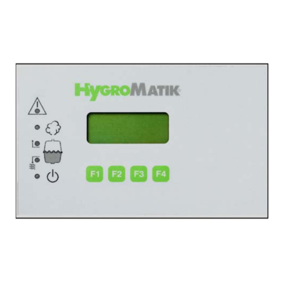
Page 23: Basic Construction
The HygroMatik control Type Basic consists of a main PCB and a display unit with icons to describe the LED. 4.2.1 Basic Display Unit Using 5 LED, the display unit of the Basic Control provides the user with information about operational conditions and fault messages:…
-
Page 24: Basic Main Pcb
Descriptions of this appear in the following sections: 4.4 Parameter Setting with Jumpers Normally, settings (parameters) for the Basic Control can only be modified using jumpers. Jumpers are small blocks with two pins over which a circuit plug can be placed, creating an electrical contact inside the plug.
-
Page 25
The jumper is referred to as “open” if there is no plug on either pin or if only one of the pins is covered. Change jumper settings only when the system is turned off. Otherwise, the control could be damaged or unpredictable func- tioning could occur. -
Page 26: Brief Description Of Jumpers
*: If jumpers A, B and C are not covered, this constitutes the factory setting for an exter- nal control signal 0-10 V DC. Other control signals ( 0-20 V DC, 0-10 mA DC) can also be handled by the Basic. However, the control must be programmed for them in the fac- tory.
-
Page 27: Explanation Of Jumper Functions
4.4.2 Explanation of Jumper Functions Jumper A / 1 Step Control or Factory Programmed If only this jumper is jumpered, the humidifier functions in a 1 step operation (On/Off). If jumpers A, B and C are open, this is the factory setting for an external control signal of 0-10 V DC.
-
Page 28
Jumper F / Less Frequent Partial Blow-Down (-50%) If this jumper is jumpered, the “less frequent partial blow-down (- 50%)” function is active. The control periodically performs a partial draining of the cylin- der (partial blow-down) in order to dilute the cylinder water; salt concentrates in it during routine operation because only pure water is evaporated. -
Page 29
Jumper E and J inverted After the preprogrammed number of operations of the main con- tactor (K1) the HygroMatik control provides the message «Main- tenance K1». During this, the green LED blinks rapidly. By appropriately setting of the jumpers, this message can be reset. -
Page 30: Description Of Potentiometer
The rated load of the relay contact is 250V/8A. 4.4.4.1 Collective Fault — Base Relay The Basic Control is normally supplied with a base relay pro- grammed for a collective fault i.e. the base relay is triggered in case of a malfunction. The potentialfree contact is shipped as a two-way contact.
-
Page 31: Humidification Signal
Collective fault reporting includes the following fault messages: • “blow-down fault” • “fault filling” • “maintenance” (only with electrode steam humidifiers) • “fault main cont.” • “fault thermo sensor” (only with unit Type HeaterLine) The switching signal which switches over the base relay may be modified using Parameter E5.
-
Page 32: Comfort And Comfort Plus
The information is provided by indicator lights and the lighted display. The standard display shows the current steam output. 5.1 Construction of Comfort and Comfort Plus Both the HygroMatik Comfort and Comfort Plus consist of a main PCB and a display unit with back-lighted display. Page 32…
-
Page 33: Comfort / Comfort Plus Display And Operation Unit
5.1.1 Comfort / Comfort Plus Display and Operation Unit Comfort Comfort — Plus Unlike the Comfort, the Comfort Plus is equipped with an addi- tional encoder knob for easy use. Turning the knob left or right is equivalent to pressing the software keys “up arrow“ or “down arrow“.
-
Page 34: Controls Comfort And Comfort — Plus
A: Malfunction (red LED) B: humidifying (yellow LED) C: Filling (yellow LED) D: Blow-down (yellow LED) E: Stand-by (green LED) When the maintenance interval is expired, the green LED blinks and “service” appears on the display. The maintenance interval can be adjusted to the existing feed water quality. For this see “maintenance interval setting.”…
-
Page 35: Manual Flush
External signals for Comfort / Comfort Plus (E3) 0(2) — 5 V DC min. 0,1 mA** 0(2) — 10 V DC min. 0,2 mA** 0(4) — 20 V DC min. 0,3 mA** 0(2) — 10 mA DC min. 1,8 V** 0(4) — 20 mA DC min.
-
Page 36: Signal Relay Pcb (Optional)
5.2 Signal Relay PCB (Optional) Please note This option is not available for electrode steam humidifiers type C01! Four additional signal relays are available with the optional sig- nal relay PCB. The possible programmable states for each relay are: 0= collective fault 1= fault data exchange 2= humidification 3= stand-by…
-
Page 37: Refitting Of Signal Relay Pcb
Signal Relay / Contacts Parameter for Factory Setting for Contact Selecting Switching Signal Switching Sig- 3. Signal Relay 37, 38, 39 Dehumidify Normally Closed Contact Normally Open Contact 4. Signal Relay 40, 41, 42 Super Flush Normally Closed Contact Normally Open Contact 5.2.1 Refitting of Signal Relay PCB: Place the socket connector JP1 of the relay signal PCB into the…
-
Page 38: Operational Conditions (Dependent On Unit Type)
6. Operational Conditions (dependent on unit type) The display shows the following operational conditions: Unit Type HyLine, CompactLine, HeaterLine, MiniSteam HeaterCompact — Humidifying / Heating up — Humidifying / Heating — Stand-by — Stand-by — No demand — No demand — Filling — Filling — Partial blow-down…
-
Page 39: Fault Messages (Comfort / Comfort Plus — Control)
Partial Blow-Down In order to dilute the concentration of the cylinder water, the con- trol performs regular partial blow-downs. Complete Blow-Down Depending on water quality, a complete blow-down is done every 3-8 days. Power Surge — Blow-Down At cold start-up, the nominal current increases to a maximum of 128% in order to achieve a rapid start-up.
-
Page 40
Blow-Down Fault The control periodically activates the blow-down pump. If no water or insufficient water is flushed out during the blow-down process, the control signals a „blow-down fault“. Thermo Sensor Activated If a thermo sensor is activated, the control indicates this as a „thermo sensor activated“… -
Page 41
Steam-Down Time Exceeded The control activates the inlet solenoid valve at time intervals when humidification is required. If the control has not activated the solenoid valve in many hours despite constant demand for humidification, the fault „Steam-down time exceeded“ appears on the display. -
Page 42: Software Menu And Parameter Setting
7. Software Menu and Parameter Setting Local communication (data entry and readout) is possible with the Comfort Control using the display and the keypad. The most important types of communication are: • Readout of important operational conditions • Selection of the active language (in Menu Mode) •…
-
Page 43: Menu Configuration
7.1 Menu Configuration System Settings Power Parameters Page 43…
-
Page 44: Readout Mode
7.2 Readout Mode Using , you can toggle between the readout values (L x) below: Readout L15 Y1 (solenoid valve) operation cycles L14 K1 (main contactor) operation cycles L13 Operating hours counter [dddd:hh] L12 Output signal [%] L7* Actual value relative humidity [% RH] L6* Desired value relative humidity [% RH] L5 steam generation output limitation [%max.output] L4 Demand [%]…
-
Page 45: Menu Mode
Filling » press Output limit. L5: 100% menu Output » press limitation P1: 100 menu Output » press limitation P1: 000 menu Output » press five times limitation P1: 000 menu Output » press limitation P1: 050 menu Output » press limitation P1: 050…
-
Page 46: Start-Up Parameters Menu
Programming sequence to modify the language: press Sprache/Language press Sprache/Language select the desired language with English confirm with Exit the language menu with Changes to the language are saved even when the unit is turned off. 7.3.2 Start-Up Parameters Menu The start-up menu comprises settings and parameters that may be needed for humidifier start-up.
-
Page 47
Para- Description Possible Settings Access Code meter Input signal 0(2)-5 VDC 0(2)-10 V DC 0(4)-20 V DC 0(4)-10 mA DC 0(4)-20 mA DC 0-140 Ohm adjustment value [+/-15%] humidity sensor E18* Offset Dehumidi- [-2 to +15%] fier Offset control [0-100%] signal sensor damping [yes/no]… -
Page 48: System Test Submenu
7.3.2.2 System Test Submenu This test enables checks of various humidifier functions (for example, during start-up). The following test routines can be executed: System Test Automatic System Test (includes all stand-alone tests) LED Test (stand-alone test) Pump/MV test (stand-alone test) Control Status Test (stand-alone test) To select the “System Test”…
-
Page 49
Pump/MV Test This test checks the function of the inlet solenoid valve and blow-down pump by filling or partially draining the cylinder. The following messages can be displayed: Sample Display Status Solenoid valve out of order; also Test valve/pump see Section „Malfunction“, Filling Fault filling Fault. -
Page 50: Electronic Name Plate Menu
Sample Display Status Safety interlock is closed. Humidi- Demand test fier operates with 1 step control. Release on Safety interlock activated (i.e. by Demand test Max.-Hygrostat). Humidifier is on Release off stand-by. Safety interlock is closed. No Demand test demand is present. The demand 6,3 V 63% percentage is displayed.
-
Page 51: Parameter Setting Menu
For security reasons, access to some parameters is protected by an entry code. Two separate access levels have been defined: • Basic customer level” without access code • Advanced customer level” with access code “010” Access Code 010 The “Parameter Setting” menu is divided into five submenus: •…
-
Page 52: Summary Table Of Parameters
7.3.4.1 Summary Table of Parameters Para- Designation Possible Settings in Menu/Submenu Access Code meter Stand-by 0 min to 999 hours Parameter Settings/ none Blow-down Blow-down parameters Stand-By heating No/Yes Interval time A17 0 — 999 min. Settings/Power Parame- ters On time A17 0 — 255 sec..
-
Page 53
Para- Designation Possible Settings in Menu/Submenu Access Code meter E6** 1. signal relay same options as with Parameter Settings/Data E5, status 2 = factory Parameters E7** 2. signal relay same options as with Parameter Settings/Data E5, status 3 = factory Parameters E8** 3. -
Page 54: Description Of Parameters
Para- Designation Possible Settings in Menu/Submenu Access Code meter time clock Switch on and switch Parameter Settings/ none off times Time Clock (only for Comfort Plus) (weekly, daily) main contactor ON (main contac- Parameter Settings switched off during tor=off) Blow-Down Parameters blow-down OFF (main contac- tor=on)
-
Page 55
E4 Adjustment Value Humidity Sensor Using this parameter, you can calibrate the active humidity sen- sor at terminals 3-5 in a range from -15% RH to +15% RH. E5 Base Relay The base relay provides a potentialfree two-way contact at ter- minals 28, 29 and 30 (rated load: 250V/8A). -
Page 56
and E18 offset dehumidifier. The hysteresis of 1% cannot be modified. A: Humidification B: Dehumidification C: Rel. Humidity RH % Example: P8 desired value rel. humidity = 50% E18 offset dehumidifier = switchover point humidification-dehumidification = 55% + 1% hysteresis In this example, the dehumidifier switches on at 56% RH and off at 55% RH. -
Page 57
Using this parameter, you specify the quantity of steam. After the steam humidifier has produced this quantity of steam, the control initiates a partial blow-down. The preset value should only be modified in consultation with HygroMatik. H12 Blow-Down Duration (only for HeaterLine Type humidifi- ers) With this parameter, you set the pump run time during partial blow-down. -
Page 58
Parameter » press Settings Code 000 Parameter Settings » press Code 010 Parameter Settings Code 010 » press Maintenance Parameter » press Maintenance interval P2: 3.00 » press Reset maintenance » press Interval P3: no Reset maintenance Interval » press P3: no Reset maintenance Interval… -
Page 59
“PI-controller” (U6=PI-controller). P11 Reset main contactor interval After the preprogrammed number of operations of the main con- tactor (K1) the HygroMatik control provides the message «Main- tenance K1». It is recommended to then swap the main contactor and erase the message. -
Page 60: T0 Time Clock
7.4.1 T0 Time Clock (available only with Comfort Plus Control) If the Timer Mode T0 is programmed to a daily or weekly period of operation and the external safety chain is closed the steam generator is released during the programmed periods. Setting the system time and date: For commissioning and after changing the battery the current system time and date has to be set.
-
Page 61: Computer Interface
The unit can be switched on and off remotely Built-In Terminal Pin Assignment C TxD B RxD A Gnd Please note For information on the Modbus RTU protocol, consult with HygroMatik. Please note Custom software adapted to interface types is written by the customer. Page 61…
-
Page 62: Parameter Setting Without Codes (P0=000) / Basic Customer Level
7.6 Parameter Setting without Codes (P0=000) / Basic Customer Level Example: The time period after which stand-by blow-down is performed (Parameter A4) should be changed from the factory setting (A4 = 24h min) to A4 = 10 h. 7.6.1 Programming Sequence for Modifying Parame- ter A4: »…
-
Page 63
twice to modify the value and confirm with Stand-by blow-down A4: 010:00 » the cursor is positioned under the 4th digit. Press 4 times to modify the value and confirm with Stand-by blow-down » exit the field with A4: 010:00 blow-down parameter »… -
Page 64: Parameter Setting With Codes (P0=010) / Advanced Customer Level
7.7 Parameter Setting with Codes (P0=010) / Advanced Customer Level Example: The control signal setting should be adjusted. The factory setting is a 0-10V signal from an external controller; this setting should be changed to activate the PI-controller to connect to an active humidity sensor with a 0-20 mA DC signal. Accordingly, the parameters must be changed as indicated below: Parameter…
-
Page 65
Output » press limitation P1: 100% Operating mode » press (= select the parameter to be modified) U6: extern. control. Operating mode » select “PI-controller” with U6: extern. control. Operating mode » confirm with U6: PI contr. Operating mode U6: PI contr. »… -
Page 66: Programming Parameter E3
7.7.2 Programming Parameter E3 Follow the same programming steps used for “Modifying Param- eter U6” (previous section), until the “Control Parameters” sub- menu is displayed: Control Parameter » press (= enter the menu) Control Parameter » press until Parameter E3 is shown P1: 100% Input signal »…
-
Page 67: Twin Cylinder Units (Hyline 60-116) And Double Units (Heaterline 60-90)
8. Twin Cylinder Units (HyLine 60-116) and Double Units (HeaterLine 60-90) The humidifiers type HyLine 60-116 are twin cylinder units. Each steam cylinder is supervised by its own control. The exter- nal control signal and the safety interlock signal have only to be connected to the terminal block of the first cylinder.
-
Page 68
The control of the second humidifer is normally a Basic control consisting of mainboard and display plate with 5 LED. The con- trol of the first humidifier can be a Basic, Comfort or Comfort Plus. To change parameters at the control of the second humidi- fier please also see chapter „Basic Control“… -
Page 69: Malfunctions And Messages / Conditions
9. Malfunctions and Messages / Conditions Switch off the steam humidifier immediately if a fault occurs! Faults are only to be remedied by qualified personnel following the pro- per safety instructions. Please note The fault messages displayed depend on the humidifier type in use;…
-
Page 70
— Water conductivity too low. cally. • — Cold start Check water values and/or con- — Re-start following full blow-down. tact HygroMatik. — Changing water conductivity. — Electrodes worn out. • Replace electrodes. • •… -
Page 71
Message / Mal- Probable Cause Resolution Display function Dis- played* • Solenoid valve or feed line is fouled or de- • Clean or replace solenoid valve Fault Filling fective. or feed line. Unit shuts off au- tomatically. • Defective coil. •… -
Page 72
Message / Mal- Probable Cause Resolution Display function Dis- played* • • Fault Activated Thermo sensor on the top of the cylinder Disconnect power supply. Wait Thermo Sensor has been activated (HeaterLine = 2 ther- until cylinder has cooled down. mo sensors, HeaterCompact = 1 thermo Press the release pin back Unit shuts off au-… -
Page 73
To avoid failure, a replacement of the The system still reset main contactor interval» for main contactor is recommended in the operates. Comfort / Comfort Plus control short term. or «Brief Description of Jump- ers» for Basic control. Page 73… -
Page 74
Possible Condi- Probable cause for fault situation Resolution tion • The unit’s steam generation output limita- • Check steam generation output set humidity level has not been tion is impeding full output limitation parameter “P1”. reached • Nominal unit output is not sufficient. •… -
Page 75
Possible Condi- Probable cause for fault situation Resolution tion • Hose clamps on the steam or condensate • Tighten hose clamps. Water is leaking from upper part of hose do not close tightly. steam cylinder. • The heater element or thermo sensor has •… -
Page 76
(brown-black deposits) and very high wa- aged. ter conductivity. In these cases, consult HygroMatik. Perform maintenance: — Replace electrodes — Clean steam cylinder — Check water quality or conduc- tivity, also see Section „Direc-… -
Page 77
** Only Comfort / Comfort Plus *** ESH = electrode steam humidifier; HE = heater element humidifier Page 77… -
Page 78: Basic Pcb Connections
10. Basic PCB Connections Main PCB Steam Humidifier current transducer(only for Humidifier type sensor electrode HyLine, CompactLine, MiniSteam) fault indicator lamp (red) controller fuse 1.6 A humidifying indicator lamp (yellow) main contactor D 63 filling indicator lamp (yellow) L1-L3 main terminal…
-
Page 79
Page 79… -
Page 80: Wiring Diagram
Steam Humidifier 28 — 30 signal relay (collective fault)(ST4) sensor electrode 31 — 42 optional: 4 signal relay ouputs (see JP3) controller fuse 1.6 A jumper terminal basic settings main contactor ST 8 connector COM-Port L1-L3 main terminal ST 9…
-
Page 81
Page 81… -
Page 82
L2 L3 L2 L3 L2 L3 L2 L3 L2 L3 L3 N N PE +24V 1,6A 13 12 Sockel / socket Basis Platine/ basic electronic Hy23-45 HY60-116 C-30-58 Meldung Befeuchten signal humidifing L1 L2 L3 L1 L2 L3 L1 L2 L3… -
Page 83
Page 83… -
Page 84
Page 84… -
Page 85
HL 12 / HL 18 HL 27 / HL18 Betriebsmeldung Betriebsmeldung operation operation Halbleiterrelais an der solid state relay Halbleiterrelais an der solid state relay Geräte-Mittelwand located at middle plate Geräte-Mittelwand located at middle plate R1 — R2 in HL12 KW Heizkörper / heating element R1 — R3 in HL27… -
Page 86
2 Halbleiterrelais 2 solid state relays Schwimmerstellung G3 max. Niveau G2 Füllen aus G1 Trockengang 13 12 Basis Platine/ basic electronic 23 24 Bauseitige Verdrahtung external wiring Leistungsteilsteil für Slave-Gerät HL 60 — 90 Steuerungsteil für Slave-Gerät HL 60 — 90… -
Page 87
Page 87… -
Page 88
Page 88… -
Page 89
Page 89… -
Page 90
Page 90… -
Page 91: Technical Specifications
12. Technical Specifications Heater Element Steam Humidifier Type HeaterLine HL06 HL09 HL12 HL18 HL24 HL27 HL30 HL36 HL45 Steam Output [kg/h] Power Rating [kW] 13,5 18,0 20,3 22,5 27,0 33,8 Power Consumption [A] 11,3 16,8 19,5 29,3 39,0 29,3 58,5 58,5 Circuit Protection [A] 3×16…
-
Page 92
Electrode Steam Humidifer Type HyLine HY05 HY08 HY13 HY17 HY23 HY30 Steam Output [kg/h] Power Rating [kW] 12,8 17,3 22,5 Power Consumption [A] 14,1 18,4 24,9 32,5 Circuit Protection [A] 3×10 3×16 3×20 3×35 3×35 Type HyLine HY45 HY60 HY90 HY116 Steam Output [kg/h] Power Rating [kW]… -
Page 93
System Settings Power Parameters Page 93… -
Page 94
Lise-Meitner-Str.3 • D-24558 Henstedt-Ulzburg Phone +49(0)4193/ 895-0 • Fax -33 eMail hy@hygromatik.de • www.hygromatik.com 12/2004 A member of the Group…