- Manuals
- Brands
- Husqvarna Manuals
- Motorcycle
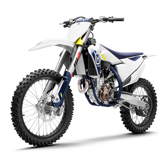
- FE 350 2022
- Owner’s manual
-
Contents
-
Table of Contents
-
Troubleshooting
-
Bookmarks
Quick Links
OWNER’S MANUAL 2022
FE 350
Art. no. 3402540en
Related Manuals for Husqvarna FE 350 2022
Summary of Contents for Husqvarna FE 350 2022
-
Page 1
OWNER’S MANUAL 2022 FE 350 Art. no. 3402540en… -
Page 3
DEAR HUSQVARNA MOTORCYCLES CUSTOMER Congratulations on your decision to purchase a Husqvarna motorcycle. You are now the owner of a state-of- DEAR HUSQVARNA MOTORCYCLES CUSTOMER the-art sports vehicle which, with appropriate care, will bring you pleasure for a long time to come. -
Page 4: Table Of Contents
TABLE OF CONTENTS TABLE OF CONTENTS 6.14 Opening fuel tank filler cap ….21 MEANS OF REPRESENTATION……6 6.15 Closing the fuel tank filler cap….. 22 Symbols used ……..6 6.16 Cold start button……… 22 Formats used ……..6 6.17 Idle speed adjusting screw ….
-
Page 5
TABLE OF CONTENTS Transporting……..40 12.9 Removing the lower triple clamp ..57 Refueling ……….40 12.10 Installing the lower triple clamp ..58 12.11 Checking the steering head bearing SERVICE SCHEDULE……..42 play …………. 60 10.1 Additional information……42 12.12 Adjusting the steering head bearing 10.2 Required work…….. -
Page 6
TABLE OF CONTENTS 13.2 Checking the brake discs ….89 TUNING THE ENGINE ……..123 13.3 Checking the front brake fluid level ..90 17.1 Checking the play in the throttle 13.4 Adding the front brake fluid …. 90 cable ……….123 13.5 Checking the front brake linings .. -
Page 7
TABLE OF CONTENTS INDEX OF SPECIAL TERMS ……157 LIST OF ABBREVIATIONS ……158 LIST OF SYMBOLS ……..159 29.1 Yellow and orange symbols….159 29.2 Green and blue symbols….159 INDEX …………..160… -
Page 8: Means Of Representation
1 MEANS OF REPRESENTATION Symbols used The meaning of specific symbols is described below. Indicates an expected reaction (e.g. of a work step or a function). Indicates an unexpected reaction (e.g. of a work step or a function). All work marked with this symbol requires specialist knowledge and technical understand- ing.
-
Page 9: Safety Advice 2
SAFETY ADVICE 2 Use definition – intended use (EU) This vehicle has been designed and built to withstand the normal stresses and strains of racing. This vehi- cle complies with the currently valid regulations and categories of the top international motorsports organi- zations.
-
Page 10: Degrees Of Risk And Symbols
2 SAFETY ADVICE Degrees of risk and symbols Danger Identifies a danger that will immediately and invariably lead to fatal or serious permanent injury if the appropriate measures are not taken. Warning Identifies a danger that is likely to lead to fatal or serious injury if the appropriate measures are not taken.
-
Page 11: Protective Clothing
– Always wear protective clothing that is in good condition and meets the legal regulations. In the interest of your own safety, Husqvarna Motorcycles recommends that you only operate the vehicle while wearing protective clothing. Work rules Unless specified otherwise, the ignition must be turned off during all work (models with ignition lock, models with remote key) or the engine must be at a standstill (models without ignition lock or remote key).
-
Page 12: Environment
Because motorcycles are not subject to the EU regulations governing the disposal of used vehicles, there are no legal regulations that pertain to the disposal of an end-of-life motorcycle. Your authorized Husqvarna Motor- cycles dealer will be glad to advise you.
-
Page 13: Important Notes 3
IMPORTANT NOTES 3 Manufacturer warranty, implied warranty The work prescribed in the service schedule must only be carried out in an authorized Husqvarna Motorcy- cles workshop and confirmed in the Husqvarna Motorcycles Dealer.net, as otherwise all warranty claims will be void. Damage or secondary damage caused by tampering with and/or conversions on the vehicle are not covered by the manufacturer warranty.
-
Page 14: Customer Service
3 IMPORTANT NOTES Customer service Your authorized Husqvarna Motorcycles dealer will be happy to answer any questions you may have regarding your vehicle and Husqvarna Motorcycles. A list of authorized Husqvarna Motorcycles dealers can be found on the Husqvarna Motorcycles website.
-
Page 15: View Of Vehicle 4
VIEW OF VEHICLE 4 View of vehicle, front left (example) F03489-10 Hand brake lever ( p. 17) Clutch lever ( p. 17) Fuel tank filler cap Air filter box cover Side stand ( p. 24) Engine number ( p. 15) Shift lever ( p.
-
Page 16: View Of Vehicle, Rear Right (Example)
4 VIEW OF VEHICLE View of vehicle, rear right (example) F03490-10 Fork compression adjuster Stop button ( p. 17) p. 18) (EU) Horn button ( Light switch ( p. 18) (EU) Turn signal switch ( p. 19) (EU) Start button ( p.
-
Page 17: Serial Numbers 5
SERIAL NUMBERS 5 Vehicle identification number The vehicle identification number is stamped on the right side of the steering head. 401945-10 Type label (EU) The Europe type label is fixed to the front of the steering head. The Canada type label is fixed to the front of the chest tube.
-
Page 18: Fork Part Number
5 SERIAL NUMBERS Fork part number The fork part number is stamped on the inner side of the fork stub. 401947-10 Shock absorber article number Shock absorber article number is stamped on the top of the shock absorber above the adjusting ring towards the engine side. H02222-10…
-
Page 19: Controls 6
CONTROLS 6 Clutch lever Clutch lever is fitted on the handlebar on the left. The clutch is activated hydraulically and adjusts itself automati- cally. F03491-10 Hand brake lever The hand brake lever is fitted on the right side of the handle- bar.
-
Page 20: Horn Button (Eu)
6 CONTROLS (US) The stop button is fitted on the left side of the handlebar. Possible states is in the basic position – In this position, • The stop button the ignition circuit is closed and the engine can be started. pressed –…
-
Page 21: Turn Signal Switch (Eu)
CONTROLS 6 Turn signal switch (EU) Turn signal switch is fitted on the left side of the handlebar. Possible states Turn signal off – The turn signal switch is in the cen- tral position. Left turn signal, on – The turn signal switch is turned to the left.
-
Page 22: Combination Switch
– The OBD has detected an error in the vehicle elec- tronics. Come safely to a halt, and contact an autho- rized Husqvarna Motorcycles workshop. The fuel level warning lamp lights up yellow – The fuel level has reached the reserve mark.
-
Page 23: Overview Of Indicator Lights (Us)
– The OBD has detected an error in the vehicle elec- tronics. Come safely to a halt, and contact an autho- rized Husqvarna Motorcycles workshop. The fuel level warning lamp lights up yellow – The fuel level has reached the reserve mark.
-
Page 24: Closing The Fuel Tank Filler Cap
6 CONTROLS 6.15 Closing the fuel tank filler cap – Mount fuel tank filler cap and turn it clockwise until the release button engages. Info Route fuel tank breather hose without kinks. F03500-10 6.16 Cold start button The cold start button is fitted to the bottom of the throttle valve body.
-
Page 25: Idle Speed Adjusting Screw
CONTROLS 6 6.17 Idle speed adjusting screw The idle setting of the throttle valve body substantially influences the vehicle’s starting behavior, a stable idle speed, and the vehi- cle’s response when the throttle is opened. An engine with a correctly set idle speed is easier to start than an engine with the idle speed set incorrectly.
-
Page 26: Foot Brake Lever
6 CONTROLS 6.19 Foot brake lever Foot brake lever is located in front of the right footrest. The rear brake is engaged with the foot brake lever. 401956-10 6.20 Side stand The side stand is attached to the left side of the vehicle. 401943-10 The side stand is used for parking the motorcycle.
-
Page 27: Locking The Steering (Eu)
CONTROLS 6 6.22 Locking the steering (EU) Note Danger of damage The parked vehicle can roll away or fall over. – Park the vehicle on a firm and level surface. – Park the vehicle. – Turn handlebar as far as possible to the right. –…
-
Page 28: Combination Instrument
Battery voltage of the combination instrument – Bat- tery voltage of the combination instrument is too low. Change combination instrument battery. Service – A service is due. Contact an authorized Husqvarna Motorcycles workshop. 401901-01 Setting the combination instrument Condition The motorcycle is stationary.
-
Page 29: Adjusting The Kilometers Or Miles
COMBINATION INSTRUMENT 7 – Wait for 5 seconds. Combination instrument changes to the next menu item. symbol flashes. – Press one of the buttons to select the 24 h display or 12 h display for the clock. 401911-01 – Wait for 5 seconds. Combination instrument changes to the next menu item.
-
Page 30: Setting The Clock
7 COMBINATION INSTRUMENT – Press and hold both buttons for 3 — 5 seconds. The Setup menu is displayed. The UNIT display flashes. – Press one of the buttons to select UNIT for the speed in kilo- meters KM/H or miles M/H. 401909-01 Setting the clock Condition…
-
Page 31: Speed, Time, And Dst Distance 1
COMBINATION INSTRUMENT 7 Switching off the service interval display – Press and hold the left button. off appears in the display. 401914-01 Speed, time, and DST distance 1 – Press one of the buttons until DST appears on the combina- tion instrument.
-
Page 32: Avg Average Speed, Art Operating Hours, And Odo Total Distance Covered
7 COMBINATION INSTRUMENT Press the left DST2 can be preset to a value between 0.0 button for 3 – and 39999.9 by pressing the buttons. 5 seconds. Press the Next display mode right button briefly. Press the DST2 is reset to 0.0. right button for 3 –…
-
Page 33: Preparing For Use 8
When using your motorcycle, remember that others may feel disturbed by excessive noise. – Make sure that the pre-sale inspection work has been carried out by an authorized Husqvarna Motorcycles workshop. You will receive a delivery certificate when the vehicle is handed over.
-
Page 34: Running-In The Engine
8 PREPARING FOR USE – Adjust basic position of the hand brake lever. ( p. 89) – Adjust the basic position of the foot brake lever. p. 95) – Adjust the basic position of the shift lever. p. 128) – Get used to the handling characteristics of the motorcycle on a suitable surface before undertaking more challenging trips.
-
Page 35: Starting Power Of Lithium-Ion Batteries At Low Temperatures
Riding at low temperatures and in snow. ( p. 35) Preparing the vehicle for riding on dry sand – Mount the air filter dust cover. Air filter dust cover (79006920000) Info Read the fitting instructions for Husqvarna Motorcy- cles accessories. 102136-01…
-
Page 36: Preparing The Vehicle For Riding On Wet Sand
8 PREPARING FOR USE – Mount the air filter sand cover. Air filter sand cover (79006922000) Info Read the fitting instructions for Husqvarna Motorcy- cles accessories. 102138-01 – Clean the chain. – Mount the steel sprocket. – Grease the chain.
-
Page 37: Preparing Vehicle For High Temperatures Or Slow Riding
Straighten bent radiator fins carefully. – Check the coolant level. ( p. 120) Preparing the vehicle for low temperatures or snow – Mount the air filter rain cover. Air filter rain cover (79006921000) Info Read the fitting instructions for Husqvarna Motorcy- cles accessories. 102137-01…
-
Page 38: Riding Instructions
9 RIDING INSTRUCTIONS Checks and maintenance measures when preparing for use Info Before every trip, check the condition of the vehicle and ensure that it is safe to operate. The vehicle must be in perfect technical condition when it is being operated. –…
-
Page 39: Activating Traction Control
RIDING INSTRUCTIONS 9 – Take the motorcycle off side stand and secure the side stand with rubber strap – Shift the transmission into neutral. (EU) – Turn the emergency OFF switch to the position Condition Ambient temperature: < 20 °C (< 68 °F) –…
-
Page 40: Starting Off
Danger of accidents A spongy pressure point on the front or rear brake reduces braking efficiency. – Check the brake system and do not continue riding until the problem is eliminated. (Your authorized Husqvarna Motorcycles workshop will be glad to help.)
-
Page 41: Stopping, Parking
RIDING INSTRUCTIONS 9 Warning Danger of accidents Moisture and dirt impair the brake system. – Brake carefully several times to dry out and remove dirt from the brake linings and the brake discs. – On sandy, wet, or slippery surfaces, use the rear brake. –…
-
Page 42: Transporting
In some countries and regions, the available fuel quality and cleanliness may not be sufficient. This will result in problems with the fuel system. – Refuel only with clean fuel that meets the specified standards. (Your authorized Husqvarna Motorcycles workshop will be glad to help.)
-
Page 43
RIDING INSTRUCTIONS 9 Note Environmental hazard Improper handling of fuel is a danger to the environment. – Do not allow fuel to enter the groundwater, the soil, or the sewage system. – Switch off engine. – Open fuel tank filler cap. ( p. -
Page 44: 10 Service Schedule
Different service intervals may apply in your country, depending on the local operating conditions. Individual service intervals and scopes may change in the course of technical developments. The most up-to- date service schedule can always be found on Husqvarna Motorcycles Dealer.net. Your authorized Husqvarna Motorcycles dealer will be glad to advise you.
-
Page 45: Recommended Work
● Final check: Check the vehicle is roadworthy and take a test ride. ○ ● ● ● ● Read out the fault memory after the test ride using the Husqvarna Motorcycles diag- nostics tool. ○ ● ● ● ● Make a service entry in Husqvarna Motorcycles Dealer.net.
-
Page 46
10 SERVICE SCHEDULE every 48 months every 12 months Every 135 operating hours Every 70 operating hours when used for motorsports After 20 operating hours After 10 operating hours ● ● Perform engine service including removing and installing the engine. (Change the spark plug and spark plug connector. -
Page 47: Tuning The Chassis 11
The shock absorber is filled with highly compressed nitrogen. – Please follow the description provided. (Your authorized Husqvarna Motorcycles workshop will be glad to help.) Info The effect of the low-speed compression adjuster can be seen in slow to normal compression of the…
-
Page 48: Adjusting The High-Speed Compression Damping Of The Shock Absorber
The shock absorber is filled with highly compressed nitrogen. – Please follow the description provided. (Your authorized Husqvarna Motorcycles workshop will be glad to help.) Info The effect of the high speed compression adjuster can be seen in the fast compression of the shock absorber.
-
Page 49: Adjusting The Rebound Damping Of The Shock Absorber
Risk of injury Parts of the shock absorber will move around if the shock absorber is detached incor- rectly. The shock absorber is filled with highly compressed nitrogen. – Please follow the description provided. (Your authorized Husqvarna Motorcycles workshop will be glad to help.) – Turn adjusting screw clockwise up to the last perceptible click.
-
Page 50: Checking The Static Sag Of The Shock Absorber
11 TUNING THE CHASSIS Finishing work – Remove the motorcycle from the lift stand. ( p. 54) 11.7 Checking the static sag of the shock absorber – Measure dimension of rear wheel unloaded. ( p. 47) – Hold the motorcycle upright with aid of an assistant. –…
-
Page 51: Adjusting The Spring Preload Of The Shock Absorber
The shock absorber is filled with highly compressed nitrogen. – Please follow the description provided. (Your authorized Husqvarna Motorcycles workshop will be glad to help.) Info Before changing the spring preload, make a note of the present setting, e.g., by measuring the spring length.
-
Page 52: Adjusting The Riding Sag
11 TUNING THE CHASSIS 11.10 Adjusting the riding sag Preparatory work – Raise the motorcycle with a lift stand. ( p. 54) – Remove the shock absorber. p. 63) – After removing the shock absorber, clean it thoroughly. Main work –…
-
Page 53: Adjusting The Compression Damping Of The Fork
TUNING THE CHASSIS 11 11.12 Adjusting the compression damping of the fork Info The hydraulic compression damping determines the fork suspension behavior. – Turn white adjuster clockwise as far as it will go. Info Adjuster is located at the upper end of the left fork leg.
-
Page 54: Adjusting The Spring Preload Of The Fork
11 TUNING THE CHASSIS Info Turn clockwise to increase the damping; turn counterclockwise to reduce damping when the shock absorber rebounds. 11.14 Adjusting the spring preload of the fork Preparatory work – Raise the motorcycle with a lift stand. ( p.
-
Page 55: Adjusting The Handlebar Position
TUNING THE CHASSIS 11 11.16 Adjusting the handlebar position Warning Danger of accidents A repaired handlebar poses a safety risk. If the handlebar is bent or straightened, the material becomes fatigued. The handlebar may break as a result. – Change the handlebar if the handlebar is damaged or bent. –…
-
Page 56: 12 Service Work On The Chassis
12 SERVICE WORK ON THE CHASSIS 12.1 Raising the motorcycle with a lift stand Note Danger of damage The parked vehicle can roll away or fall over. – Park the vehicle on a firm and level surface. – Raise the motorcycle at the frame underneath the engine. Lift stand (81329955100) Neither wheel is in contact with the ground.
-
Page 57: Cleaning The Dust Boots Of The Fork Legs
SERVICE WORK ON THE CHASSIS 12 12.4 Cleaning the dust boots of the fork legs Preparatory work – Raise the motorcycle with a lift stand. ( p. 54) – Remove the fork protector. ( p. 55) Main work – Push dust boots of both fork legs downward.
-
Page 58: Installing The Fork Protector
12 SERVICE WORK ON THE CHASSIS 12.6 Installing the fork protector – Position the fork protector on the left fork leg. Mount and tighten screws Guideline Remaining screws, 10 Nm (7.4 lbf ft) chassis – Position the brake line, wiring harness, and clamp. Mount and tighten screws –…
-
Page 59: Installing The Fork Legs
SERVICE WORK ON THE CHASSIS 12 12.8 Installing the fork legs Main work – Position the fork legs. Bleeder screws are positioned toward the front. Info The compression damping is located in left fork leg COMP (white adjuster). The rebound damping is located in right fork leg REB (red adjuster).
-
Page 60: Installing The Lower Triple Clamp
12 SERVICE WORK ON THE CHASSIS Main work – Remove screw – Remove screw – Open cable holder in front of the left radiator and detach the clutch line. – Take off the upper triple clamp with the handlebar and set aside.
-
Page 61
SERVICE WORK ON THE CHASSIS 12 – Position the upper triple clamp with the handlebar. – Mount screw , but do not tighten yet. – Mount the clutch line with cable holder S03552-11 – Position the fork legs. Bleeder screws are positioned toward the front. -
Page 62: Checking The Steering Head Bearing Play
Danger of accidents Incorrect steering head bearing play impairs the handling characteristic and damages components. – Correct incorrect steering head bearing play immediately. (Your authorized Husqvarna Motorcycles workshop will be glad to help.) Info If the vehicle is operated for a lengthy period with play in the steering head bearing, the bearings and the bearing seats in the frame can become damaged over time.
-
Page 63: Adjusting The Steering Head Bearing Play
SERVICE WORK ON THE CHASSIS 12 Main work – Move the handlebar to the straight-ahead position. Move the fork legs to and fro in the direction of travel. Play should not be detectable on the steering head bear- ing. » If there is detectable play: –…
-
Page 64: Lubricating The Steering Head Bearing
12 SERVICE WORK ON THE CHASSIS 12.13 Lubricating the steering head bearing – Remove the lower triple clamp. p. 57) – Install the lower triple clamp. p. 58) Info The steering head bearing is cleaned and lubricated in the course of removal and installation of the lower triple clamp.
-
Page 65: Installing Front Fender
SERVICE WORK ON THE CHASSIS 12 12.15 Installing front fender Main work – Position front fender. Mount and tighten screws Guideline Remaining screws, 10 Nm (7.4 lbf ft) chassis – Mount and tighten screws Guideline Remaining screws, 10 Nm (7.4 lbf ft) chassis H03691-10 Finishing work…
-
Page 66
12 SERVICE WORK ON THE CHASSIS – Press angle lever toward the rear. – Press linkage lever downward. H03694-10 (EU) – Disconnect the plug-in connector of the brake light switch. F03465-10 – Remove screws – Pull off foot brake cylinder from the push rod. F03466-10 –… -
Page 67: Installing The Shock Absorber
SERVICE WORK ON THE CHASSIS 12 – Hold the shock absorber and remove screw – Remove the shock absorber carefully at the bottom. F03469-10 12.17 Installing the shock absorber Main work – Carefully position the shock absorber into the vehicle from the bottom.
-
Page 68: Removing The Seat
12 SERVICE WORK ON THE CHASSIS – Position the foot brake cylinder. Push rod engages in the foot brake cylinder. The dust boot is correctly positioned. – Mount and tighten screws Guideline Remaining screws, 10 Nm (7.4 lbf ft) chassis F03472-10 –…
-
Page 69: Mounting The Seat
SERVICE WORK ON THE CHASSIS 12 Main work – Remove screw with the bushing. – Pull seat back and lift it off. S03559-10 12.19 Mounting the seat Main work – Mount the front of the seat on the collar bushing of the fuel tank and the rear in the bracket.
-
Page 70: Removing The Air Filter Box Cover
12 SERVICE WORK ON THE CHASSIS 12.20 Removing the air filter box cover – Pull off the air filter box cover sideways in areas and take off toward the rear. F02311-10 12.21 Installing the air filter box cover – Attach catch of the air filter box in area and push for- ward.
-
Page 71: Installing The Air Filter
SERVICE WORK ON THE CHASSIS 12 Main work – Detach retaining tab . Remove air filter with air filter sup- port. – Remove air filter from air filter support. F02313-10 12.23 Installing the air filter Main work – Mount the clean air filter on the air filter support. –…
-
Page 72: Removing The Right Side Cover
12 SERVICE WORK ON THE CHASSIS Main work – Wash the air filter thoroughly in special cleaning liquid and allow it to dry properly. Air filter cleaner ( p. 154) Info Only press the air filter to dry it, never wring it out. –…
-
Page 73: Installing The Right Side Cover
SERVICE WORK ON THE CHASSIS 12 12.26 Installing the right side cover Main work – Attach side cover with the holding lugs from below and push upward. – Engage the side cover in areas F03474-10 Finishing work – Mount the seat. ( p.
-
Page 74: Installing The Main Silencer
12 SERVICE WORK ON THE CHASSIS 12.28 Installing the main silencer Main work (EU) – Position the catalytic converter in the main silencer. S02101-10 – Position the main silencer. – Mount screws , but do not tighten yet. – Attach spring Spring hook (50305017000C1) –…
-
Page 75
SERVICE WORK ON THE CHASSIS 12 S03542-10 Main work – Remove all screws, take off silencer cap with O-ring Info Do not remove the glass fiber yarn filling. Caution Danger to health Soot particles irritate the eyes and mucuous membranes. – Wear suitable breathing and eye protection when cleaning the main silencer and carbon screen. -
Page 76: Changing The Glass Fiber Yarn Filling In The Main Silencer
12 SERVICE WORK ON THE CHASSIS 12.30 Changing the glass fiber yarn filling in the main silencer Warning Danger of burns The exhaust system gets very hot when the vehicle is driven. – Allow the exhaust system to cool down before performing any work on the vehicle. Info Over time, the fibers of the glass fiber yarn filling escape and the damper «burns»…
-
Page 77: Removing The Fuel Tank
SERVICE WORK ON THE CHASSIS 12 (US) – Remove all the screws on the main silencer. – Take off silencer cap with the filter and O-ring – Remove glass fiber yarn filling from main silencer – Clean the parts that need to be reinstalled and check for damage.
-
Page 78
12 SERVICE WORK ON THE CHASSIS – Remove the seat. ( p. 66) – Remove the right side cover. ( p. 70) Main work – Unplug connector of the fuel pump. – Clean quick release coupling thoroughly with compressed air. Info Under no circumstances should dirt enter into the fuel line. -
Page 79: Installing The Fuel Tank
SERVICE WORK ON THE CHASSIS 12 12.32 Installing the fuel tank Danger Fire hazard Fuel is highly flammable. The fuel in the fuel tank expands when warm and can escape if overfilled. – Do not fuel the vehicle in the vicinity of open flames or lit cigarettes. –…
-
Page 80: Checking For Chain Dirt Accumulation
12 SERVICE WORK ON THE CHASSIS (EU) – Position the horn with the horn bracket. – Mount and tighten screws Guideline Remaining screws, 10 Nm (7.4 lbf ft) chassis H03705-11 – Plug in connector for the fuel pump. – Remove the wash cap set. –…
-
Page 81: Cleaning The Chain
SERVICE WORK ON THE CHASSIS 12 12.34 Cleaning the chain Warning Danger of accidents Lubricants on the tires reduces the road grip. – Remove lubricants from the tires using a suitable cleaning agent. Warning Danger of accidents Oil or grease on the brake discs reduces the braking effect. –…
-
Page 82: Adjusting The Chain Tension
12 SERVICE WORK ON THE CHASSIS Main work – Pull the chain at the end of the chain sliding piece upward to measure chain tension Info Lower chain section must be taut. When the chain guard is mounted, it must be possi- ble to pull up the chain at least to the point where it makes contact with chain guard Chain wear is not always even, so you should repeat…
-
Page 83: Checking The Chain, Rear Sprocket, Engine Sprocket, And Chain Guide
SERVICE WORK ON THE CHASSIS 12 Main work – Loosen nut – Loosen nuts – Adjust the chain tension by turning adjusting screws left and right. Guideline Chain tension 55 … 58 mm (2.17 … 2.28 in) Turn adjusting screws on the left and right so that the markings on the left and right chain adjusters are in the same position relative to reference marks…
-
Page 84
12 SERVICE WORK ON THE CHASSIS – Pull on the top section of the chain with the specified weight Guideline Weight of chain wear mea- 10 … 15 kg (22 … 33 lb.) surement – Measure distance of 18 chain rollers in the lower chain section. -
Page 85
SERVICE WORK ON THE CHASSIS 12 – Check chain sliding piece for wear. » If the lower edge of the chain pins is in line with or below the chain sliding piece: – Change the chain sliding piece. – Check that the chain sliding piece is firmly seated. »… -
Page 86: Checking The Frame
If the link fork exhibits damage, cracking, or deformation: – Change the link fork. Info Always replace a damaged link fork. Repair of the link fork is not authorized by Husqvarna Motorcycles. 401520-01 12.40 Checking the throttle cable routing Preparatory work –…
-
Page 87: Checking The Rubber Grip
SERVICE WORK ON THE CHASSIS 12 Finishing work – Install the fuel tank. p. 77) – Install the right side cover. ( p. 71) – Mount the seat. ( p. 67) – Install the air filter box cover. ( p. 68) 12.41 Checking the rubber grip –…
-
Page 88: Checking/Correcting The Fluid Level Of Hydraulic Clutch
12 SERVICE WORK ON THE CHASSIS Info Turn the adjusting screw clockwise to increase the distance between the clutch lever and the handlebar. Turn the adjusting screw counterclockwise to decrease the distance between the clutch lever and the handlebar. The range of adjustment is limited. Turn the adjusting screw by hand only, and do not apply any force.
-
Page 89: Changing The Hydraulic Clutch Fluid
SERVICE WORK ON THE CHASSIS 12 Info Immediately clean up any brake fluid that has over- flowed or spilled with water. 12.44 Changing the hydraulic clutch fluid Warning Skin irritation Brake fluid causes skin irritation. – Keep brake fluid out of the reach of children. –…
-
Page 90: Removing The Engine Guard
12 SERVICE WORK ON THE CHASSIS – Now inject fluid into the system until it escapes from the openings of the master cylinder without bubbles. – Occasionally extract the fluid from the master cylinder reser- voir to prevent overflowing. – Remove the bleeding syringe.
-
Page 91: Brake System 13
Warning Danger of accidents Worn-out brake discs reduce the braking effect. – Make sure that worn-out brake discs are replaced immediately. (Your authorized Husqvarna Motor- cycles workshop will be glad to help.) – Check the front and rear brake disc thickness at multiple…
-
Page 92: Checking The Front Brake Fluid Level
– Make sure that brake fluid for the front and rear brake is changed in accordance with the service schedule. (Your authorized Husqvarna Motorcycles workshop will be glad to help.) – Move the brake fluid reservoir mounted on the handlebar to a horizontal position.
-
Page 93: Checking The Front Brake Linings
Checking the front brake linings Warning Danger of accidents Worn-out brake linings reduce the braking effect. – Ensure that worn-out brake linings are replaced immediately. (Your authorized Husqvarna Motorcy- cles workshop will be glad to help.) – Check the brake linings for minimum thickness ≥…
-
Page 94: Changing The Brake Linings Of The Front Brake
Danger of accidents Brake linings which have not been approved alter the braking efficiency. Not all brake linings are tested and approved for Husqvarna motorcycles. The structure and friction coefficient of the brake linings, and thus their brake power, may vary greatly from that of original brake linings.
-
Page 95
BRAKE SYSTEM 13 – Move the brake fluid reservoir mounted on the handlebar to a horizontal position. – Remove screws – Take off cover with membrane F03508-10 – Manually press the brake caliper toward the brake disc to push back the brake pistons. Ensure that brake fluid does not flow out of the brake fluid reservoir, extract some if neces- sary. -
Page 96: Checking The Free Travel Of Foot Brake Lever
13 BRAKE SYSTEM – Add brake fluid up to level Guideline 5 mm (0.2 in) Level (brake fluid level below reservoir rim) Brake fluid DOT 4 / DOT 5.1 ( p. 152) – Position cover with membrane – Mount and tighten screws Info Use water to immediately clean up any brake fluid that has overflowed or spilled.
-
Page 97: Adjusting The Basic Position Of The Foot Brake Lever
Warning Danger of accidents Old brake fluid reduces the braking effect. – Make sure that brake fluid for the front and rear brake is changed in accordance with the service schedule. (Your authorized Husqvarna Motorcycles workshop will be glad to help.)
-
Page 98: Adding Rear Brake Fluid
Danger of accidents Old brake fluid reduces the braking effect. – Make sure that brake fluid for the front and rear brake is changed in accordance with the service schedule. (Your authorized Husqvarna Motorcycles workshop will be glad to help.) Note Environmental hazard Hazardous substances cause environmental damage.
-
Page 99: Checking The Rear Brake Linings
Checking the rear brake linings Warning Danger of accidents Worn-out brake linings reduce the braking effect. – Ensure that worn-out brake linings are replaced immediately. (Your authorized Husqvarna Motorcy- cles workshop will be glad to help.) – Check the brake linings for minimum thickness ≥…
-
Page 100
Danger of accidents Brake linings which have not been approved alter the braking efficiency. Not all brake linings are tested and approved for Husqvarna motorcycles. The structure and friction coefficient of the brake linings, and thus their brake power, may vary greatly from that of original brake linings. -
Page 101
BRAKE SYSTEM 13 – Remove the brake linings. – Clean the brake caliper and the brake caliper bracket. – Check that spring plate in the brake caliper and brake pad sliding plate in the brake caliper bracket are fitted correctly. –… -
Page 102: 14 Wheels, Tires
14 WHEELS, TIRES 14.1 Removing the front wheel Preparatory work – Raise the motorcycle with a lift stand. ( p. 54) Main work – Manually press the brake caliper toward the brake disc to push back the brake pistons. Info Make sure that you do not press the brake caliper against the spokes when pushing back the brake pis- tons.
-
Page 103: Installing The Front Wheel
WHEELS, TIRES 14 14.2 Installing the front wheel Warning Danger of accidents Oil or grease on the brake discs reduces the braking effect. – Always keep the brake discs free of oil and grease. – Clean the brake discs with brake cleaner when necessary. –…
-
Page 104: Installing The Rear Wheel
14 WHEELS, TIRES Main work – Manually press the brake caliper toward the brake disc to push back the brake piston. Info Make sure that you do not press the brake caliper against the spokes when pushing back the brake pis- ton.
-
Page 105
WHEELS, TIRES 14 Main work – Check the wheel bearing for damage and wear. » If the wheel bearing is damaged or worn: – Change the rear wheel bearing. – Clean and grease shaft seal rings and contact surfaces of the spacers. Long-life grease ( p. -
Page 106: Checking The Tire Condition
Checking the tire condition Info Only mount tires approved and/or recommended by Husqvarna Motorcycles. Other tires could have a negative effect on handling characteristics. The type, condition, and pressure of the tires all have a major impact on the handling characteristic of the motorcycle.
-
Page 107: Checking Spoke Tension
Other spokes will become looser as a result. – Check spoke tension regularly, and in particular on a new vehicle. (Your authorized Husqvarna Motorcycles workshop will be glad to help.) –…
-
Page 108: 15 Electrical System
15 ELECTRICAL SYSTEM 15.1 Removing the 12-V battery Note Environmental hazard 12 V batteries contain environmentally hazardous materials. – Do not dispose of 12 V batteries as household waste. – Dispose of 12 V batteries at a collection point for used batteries. Note Environmental hazard Hazardous substances cause environmental damage.
-
Page 109: Installing The 12-V Battery
ELECTRICAL SYSTEM 15 – Detach wiring harness , disconnect relays and hang them to the side. S03579-10 – Remove screw and unhook the holding bracket. – Lift out the 12-V battery. S03582-10 15.2 Installing the 12-V battery Main work – Insert the 12-V battery into the battery compartment with the terminals facing forward and secure with holding bracket 12-V battery (HJTZ5S-FP-C) (…
-
Page 110
15 ELECTRICAL SYSTEM – Place the relays on the holding bracket and attach wiring harness S03579-11 – Attach starter relay and fuse box to the holding bracket. S03578-11 – Connect positive cable to the 12-V battery. Guideline Screw, battery termi- 2.5 Nm (1.84 lbf ft) Info Contact disk… -
Page 111: Charging The 12-V Battery
ELECTRICAL SYSTEM 15 15.3 Charging the 12-V battery Warning Risk of injury 12 V batteries contain harmful substances. – Keep 12 V batteries out of the reach of children. – Keep sparks and open flames away from 12 V batteries. – Only charge 12 V batteries in well-ventilated rooms.
-
Page 112: Changing Main Fuse
12-V battery with this battery charger. The charg- ing time may be longer at low temperatures. This battery charger is only suitable for lithium iron phosphate batteries. Read the accompanying instruc- tions for Husqvarna Motorcycles accessories. Info Never remove cover –…
-
Page 113: Changing The Fuses Of Individual Electrical Power Consumers
ELECTRICAL SYSTEM 15 Main work – Pull starter relay from the holder. S03588-10 – Take off protection caps – Remove faulty main fuse Info A faulty fuse has a burned-out fuse wire A spare fuse is located in the starter relay. –…
-
Page 114
15 ELECTRICAL SYSTEM Guideline (EU) Fuse 1 – 10 A – EFI control unit, lambda sensor, combi- nation instrument, combination switch (optional), elec- tronic fuel injection, diagnostics connector, fuel vapor retention system, fuse 4 Fuse 2 ‑ 10 A ‑ high beam, low beam, position light, tail light, license plate lamp Fuse 3 — 10 A — radiator fan, horn, brake light, turn sig- Fuse 4 — 5 A — fuel pump… -
Page 115: Removing The Headlight Mask With The Headlight
ELECTRICAL SYSTEM 15 15.6 Removing the headlight mask with the headlight – Loosen rubber straps . Slide the headlight mask up and swing it forward. H03749-10 – Remove screw – Detach the brake line and wiring harness from the headlight mask.
-
Page 116
15 ELECTRICAL SYSTEM (US) – Join plug-in connector H03751-11 – Position the brake line and the wiring harness in the cable guide. – Mount and tighten screw – Position the headlight mask. The holding lugs engage in the fender. H03752-10 –… -
Page 117: Changing The Headlight Bulb
ELECTRICAL SYSTEM 15 15.8 Changing the headlight bulb Note Damage to reflector Grease on the reflector reduces the light intensity. Grease on the bulb will evaporate due to the heat and be deposited on the reflector. – Clean and degrease the bulbs before mounting. –…
-
Page 118: Checking The Headlight Setting
15 ELECTRICAL SYSTEM Main work – Remove the screw on the rear of the turn signal housing. – Carefully remove turn signal glass – Lightly squeeze orange cap in the area of the holding lugs and take it off. – Press the turn signal bulb lightly into the socket, turn it coun- terclockwise by about 30°, and pull it out of the socket.
-
Page 119: Adjust The Headlight Range
ELECTRICAL SYSTEM 15 15.11 Adjust the headlight range. Preparatory work – Check the headlight setting. ( p. 116) Main work – Loosen screw – Adjust the headlight range by pivoting the headlight. Guideline The boundary between light and dark must be exactly on the lower mark for a motorcycle with rider (instructions on how to apply the mark: Checking the headlight setting).
-
Page 120: Diagnostics Connector
15 ELECTRICAL SYSTEM Finishing work – Install the headlight mask with the headlight. ( p. 113) – Check the headlight setting. ( p. 116) – Set the combination instrument. ( p. 26) 15.13 Diagnostics connector Diagnostics connector is located under the seat. H00933-12…
-
Page 121: Cooling System 16
COOLING SYSTEM 16 16.1 Cooling system Water pump in the engine ensures forced circulation of the coolant. The pressure resulting from the warming of the cooling system is regulated by a valve in radiator cap . This ensures that operat- ing the vehicle at the specified coolant temperature will not result in a risk of malfunctions.
-
Page 122: Checking The Coolant Level
16 COOLING SYSTEM Coolant ( p. 152) – Mount the radiator cap. 16.3 Checking the coolant level Warning Danger of scalding During motorcycle operation, the coolant gets very hot and is under pressure. – Do not open the radiator, the radiator hoses or other cooling system components if the engine or the cooling system are at operating temperature.
-
Page 123: Refilling With Coolant
COOLING SYSTEM 16 Warning Danger of poisoning Coolant is toxic and a health hazard. – Keep coolant out of the reach of children. – Do not allow coolant to come into contact with the skin, the eyes and clothing. – Consult a doctor immediately if coolant is swallowed. –…
-
Page 124: Changing The Coolant
16 COOLING SYSTEM – Check the coolant level. ( p. 120) 16.6 Changing the coolant Warning Danger of scalding During motorcycle operation, the coolant gets very hot and is under pressure. – Do not open the radiator, the radiator hoses or other cooling system components if the engine or the cooling system are at operating temperature.
-
Page 125: Tuning The Engine 17
TUNING THE ENGINE 17 17.1 Checking the play in the throttle cable – Check the throttle grip for smooth operation. – Move the handlebar to the straight-ahead position. Turn the throttle grip back and forth slightly and determine the play in throttle cable Play in throttle cable 3 ……
-
Page 126: Adjusting The Characteristic Map Of The Throttle Response
17 TUNING THE ENGINE Main work – Move the handlebar to the straight-ahead position. – Push back sleeve – Loosen nut – Turn adjusting screw in as far as possible. – Loosen nut – Push cold start button all the way to the stop. –…
-
Page 127
TUNING THE ENGINE 17 – Remove guide plate from handle tube – Position the required guide plate on the grip tube. Guideline The label OUTSIDE must be visible. Marking must be positioned at marking Grey guide plate (79002014000) Alternative 1 Black guide plate (79002014100) Info The gray guide plate opens the throttle valve more… -
Page 128: Changing The Mapping
Adjusting the idle speed Warning Danger of accidents The engine may go out spontaneously if the idle speed is set too low. – Set the idle speed to the specified value. (Your authorized Husqvarna Motorcycles workshop will be glad to help.)
-
Page 129: Programming The Throttle Valve Position
TUNING THE ENGINE 17 – Run the engine until warm. The cold start button is deactivated – The cold start but- ton is in its basic position. ( p. 22) Danger Danger of poisoning Exhaust gases are toxic and inhaling them may result in unconsciousness and death.
-
Page 130: Checking The Basic Position Of The Shift Lever
17 TUNING THE ENGINE 17.7 Checking the basic position of the shift lever Info When driving, the shift lever must not touch the rider’s boot when in the basic position. When the shift lever keeps touching the boot, the transmission will be subject to an excessive load. –…
-
Page 131: Service Work On The Engine 18
SERVICE WORK ON THE ENGINE 18 18.1 Changing the fuel screen Danger Fire hazard Fuel is highly flammable. The fuel in the fuel tank expands when warm and can escape if overfilled. – Do not fuel the vehicle in the vicinity of open flames or lit cigarettes. –…
-
Page 132: Checking The Engine Oil Level
18 SERVICE WORK ON THE ENGINE Danger Danger of poisoning Exhaust gases are toxic and inhaling them may result in unconsciousness and death. – Always make sure there is sufficient ventilation when running the engine. – Use effective exhaust extraction when starting or running the engine in an enclosed space.
-
Page 133
SERVICE WORK ON THE ENGINE 18 Info Drain the engine oil with the engine at operating temperature. Preparatory work – Park the motorcycle on a level surface. – Remove the engine guard. ( p. 88) Main work – Position an appropriate container under the engine. –… -
Page 134
18 SERVICE WORK ON THE ENGINE – Remove screws . Remove the oil filter cover with the O- ring. V01397-10 – Pull oil filter out of the oil filter housing. Lock ring plier (51012011000) – Allow the engine oil to drain completely. –… -
Page 135: Adding Engine Oil
Engine oil (SAE 10W/50) ( p. 152) Info In order to achieve optimal engine oil performance, it is not advisable to mix different engine oils. Husqvarna Motorcycles recommends changing the engine oil. – Mount and tighten the filler plug together with the O-ring. Danger Danger of poisoning Exhaust gases are toxic and…
-
Page 136: 19 Cleaning, Care
19 CLEANING, CARE 19.1 Cleaning the motorcycle Note Material damage Components become damaged or destroyed if a pressure cleaner is used incorrectly. The high pressure forces water into the electrical components, connectors, throttle cables, and bearings, etc. Pressure which is too high causes malfunctions and destroys components. –…
-
Page 137: Checks And Maintenance Steps For Winter Operation
CLEANING, CARE 19 – Treat bare metal (except for brake discs and the exhaust sys- tem) with a corrosion inhibitor. Preserving materials for paints, metal and rubber p. 154) – Treat all plastic parts and powder-coated parts with a mild cleaning and care product.
-
Page 138: 20 Storage
– Store the vehicle in a dry location that is not subject to large fluctuations in temperature. Info Husqvarna Motorcycles recommends raising the motorcycle. – Raise the motorcycle with a lift stand. ( p. 54) –…
-
Page 139: Preparing For Use After Storage
STORAGE 20 Info Avoid running the engine for a short time only. Since the engine cannot warm up properly, the water vapor produced during combustion condenses and causes valves and the exhaust system to rust. 20.2 Preparing for use after storage –…
-
Page 140: 21 Troubleshooting
Check the electrical system. – Error in the electronic fuel Read out the fault memory using the injection Husqvarna Motorcycles diagnostics tool. – Engine does not speed up Error in the electronic fuel Read out the fault memory using the…
-
Page 141
– Read out the fault memory using the Husqvarna Motorcycles diagnostics tool. – High oil consumption Engine vent hose bent Route the vent hose without bends or replace it if necessary. -
Page 142
21 TROUBLESHOOTING Faults Possible cause Action – The high beam, low beam, tail Fuse 2 blown Change the fuses of individual electri- light, position light, and license cal power consumers. ( p. 111) plate lamp are not working – The horn, brake light, turn sig- Fuse 3 blown Change the fuses of individual electri- nal, and radiator fan are not… -
Page 143: Blink Code 22
BLINK CODE 22 Info The blink codes are only displayed by the derestricted version of the vehicle. Blink code for malfunc- tion indicator lamp 02a Malfunction indicator lamp flashes 2x per second Error level condition Throttle valve position programming necessary Blink code for malfunc- tion indicator lamp 02 Malfunction indicator lamp flashes 2x short…
-
Page 144
22 BLINK CODE Blink code for malfunc- tion indicator lamp 33 Malfunction indicator lamp flashes 3x long, 3x short Error level condition Injector cylinder 1 — circuit fault Blink code for malfunc- tion indicator lamp 37 Malfunction indicator lamp flashes 3x long, 7x short Error level condition Ignition coil 1, cylinder 1 — circuit fault Blink code for malfunc-… -
Page 145: Technical Data 23
TECHNICAL DATA 23 23.1 Engine Design 1-cylinder 4-stroke engine, water-cooled Displacement 349.7 cm³ (21.34 cu in) Stroke 57.5 mm (2.264 in) Bore 88 mm (3.46 in) Compression ratio 13.5:1 Idle speed 1,950 … 2,050 rpm Control DOHC, four valves controlled via cam lever, drive via timing chain Valve diameter, intake 36.3 mm (1.429 in)
-
Page 146: Engine Tightening Torques
23 TECHNICAL DATA 23.2 Engine tightening torques Nozzle, crank chamber ventilation 2 Nm (1.5 lbf ft) ® Loctite 243™ Oil nozzle for clutch lubrication 2 Nm (1.5 lbf ft) ® Loctite 243™ Oil nozzle for conrod bearing 2 Nm (1.5 lbf ft) ®…
-
Page 147
TECHNICAL DATA 23 Screw, oil filter cover 10 Nm (7.4 lbf ft) Screw, shift drum locating 10 Nm (7.4 lbf ft) ® Loctite 243™ Screw, shift lever 14 Nm (10.3 lbf ft) ® Loctite 243™ Screw, starter motor 10 Nm (7.4 lbf ft) Screw, starter motor — intermedi- 10 Nm (7.4 lbf ft) ®… -
Page 148: Capacities
23 TECHNICAL DATA Nut, inner clutch hub M18x1.5 100 Nm (73.8 lbf ft) ® Loctite 243™ Nut, primary gear wheel M18LHx1.5 120 Nm (88.5 lbf ft) ® Loctite 243™ Screw plug, oil screen M20x1.5 15 Nm (11.1 lbf ft) Plug, timing chain tensioner M24x1.5 40 Nm (29.5 lbf ft) Screw, alternator cover…
-
Page 149: Electrical System
80/100 — 21 M/C 51M TT 110/100 — 18 M/C 64M TT Dunlop GEOMAX AT 81 F Dunlop GEOMAX AT81 The tires specified represent one of the possible series production tires. Additional information is available in the Service section under: www.husqvarna-motorcycles.com…
-
Page 150: Fork
23 TECHNICAL DATA 23.7 Fork Fork article number 0266C169V401000 Fork WPXPLOR 5548 Compression damping Comfort 18 clicks Standard 15 clicks Sport 12 clicks Rebound damping Comfort 18 clicks Standard 15 clicks Sport 12 clicks Spring preload – preload adjuster Comfort Standard Sport Spring length with preload spacer(s)
-
Page 151: Chassis Tightening Torques
TECHNICAL DATA 23 Spring length 260 mm (10.24 in) Gas pressure 10 bar (145 psi) Static sag 37 mm (1.46 in) Riding sag 110 mm (4.33 in) Fitted length 477 mm (18.78 in) Shock absorber oil Shock absorber fluid (SAE 2.5) (50180751S1) ( p.
-
Page 152
23 TECHNICAL DATA Nut, starter motor 4 Nm (3 lbf ft) Nut, throttle cable on throttle 3 Nm (2.2 lbf ft) valve body Remaining nuts, chassis 10 Nm (7.4 lbf ft) Remaining screws, chassis 10 Nm (7.4 lbf ft) Screw, ball joint of push rod on 10 Nm (7.4 lbf ft) Loctite ®… -
Page 153
TECHNICAL DATA 23 Screw, wheel speed sensor on 4.5 Nm (3.32 lbf ft) axle clamp Nut, pull switch (US) M8x1 0.8 Nm (0.59 lbf ft) Engine attachment bolt 60 Nm (44.3 lbf ft) Remaining nuts, chassis 45 Nm (33.2 lbf ft) Remaining screws, chassis 45 Nm (33.2 lbf ft) Screw, bottom shock absorber… -
Page 154: 24 Substances
24 SUBSTANCES Brake fluid DOT 4 / DOT 5.1 Standard/classification – Guideline – Use only brake fluid that complies with the specified standard (see specifications on the container) and that exhibits the corresponding properties. Recommended supplier Castrol – REACT PERFORMANCE DOT 4 ®…
-
Page 155
SUBSTANCES 24 Fork oil (SAE 4) (48601166S1) Standard/classification – SAE ( p. 156) (SAE 4) Guideline – Use only oils that comply with the specified standards (see specifications on the container) and that exhibit the corresponding properties. Shock absorber fluid (SAE 2.5) (50180751S1) Standard/classification –… -
Page 156: 25 Auxiliary Substances
25 AUXILIARY SUBSTANCES Air filter cleaner Recommended supplier ® MOTOREX – Racing Bio Dirt Remover Chain cleaner Recommended supplier ® MOTOREX – Chain Clean High viscosity grease Recommended supplier ® – LGHB 2 Long-life grease Recommended supplier ® MOTOREX – Bike Grease 2000 Off-road chain spray Recommended supplier…
-
Page 157
AUXILIARY SUBSTANCES 25 Universal oil spray Recommended supplier ® MOTOREX – Joker 440 Synthetic… -
Page 158: 26 Standards
26 STANDARDS JASO T903 MA2 Different technical development directions required a separate specification for motorcycles – the JASO T903 MA2 standard. Earlier, engine oils from the automobile industry were used for motorcycles because there was no separate motorcycle specification. Whereas long service intervals are demanded for automobile engines, the focus for motorcycle engines is on high performance at high engine speeds.
-
Page 159: Index Of Special Terms 27
INDEX OF SPECIAL TERMS 27 On-board diagnosis Vehicle system, which monitors the specified param- eters of the vehicle electronics…
-
Page 160: 28 List Of Abbreviations
28 LIST OF ABBREVIATIONS Art. no. Article number circa compare e.g. for example etc. et cetera i.a. inter alia number poss. possibly…
-
Page 161: List Of Symbols 29
Malfunction indicator lamp lights up/flashes yellow – The OBD has detected an error in the vehicle electronics. Come safely to a halt, and contact an authorized Husqvarna Motorcy- cles workshop. The fuel level warning lamp lights up yellow – The fuel level has reached the reserve mark.
-
Page 162: Index
INDEX INDEX Chain guide checking ……81 12-V battery Chain tension charging ……109 adjusting .
-
Page 163
INDEX Engine guard Fuse installing ……88 main fuse, changing ….110 removing . -
Page 164
INDEX Manufacturer warranty ….11 removing ……66 Mapping Service . -
Page 165
INDEX Tire pressure checking ……104 Traction control activating ……37 Transporting . -
Page 166
*3402540en* 3402540en 04/2021 Husqvarna Motorcycles GmbH Stallhofnerstraße 3 5230 Mattighofen Austria Photo: Mitterbauer/KISKA, www.husqvarna-motorcycles.com Husqvarna Motorcycles GmbH…
Husqvarna Motorcycles
Здесь вы найдёте одежду, экипировку, аксессуары, тюнинг и запчасти Husqvarna Motorcycles.
- Телефон
- +7 (495) 646-11-49
- info@husqvarna-motorcycles.ru
- Адрес
- Московская обл., Ленинский р-н, д. Ближние Прудищи, вл.1, стр.1
- Время работы
- Пн-Пт 11:00 — 17:00
Следите за нами в соцсетях
- Manuals
- Brands
- Husqvarna Manuals
- Motorcycle
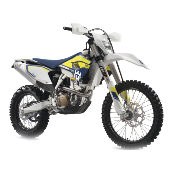
- FE 350 2016
- Repair manual
-
Bookmarks
Quick Links
PIONEERING SINCE 1903
REPAIR MANUAL2016
FE 350
FE 350 S
®
Husqvarna
Art. no. 3403027en
MOTORCYCLES
Related Manuals for Husqvarna FE 350 2016
Summary of Contents for Husqvarna FE 350 2016
-
Page 1
PIONEERING SINCE 1903 REPAIR MANUAL2016 FE 350 FE 350 S ® Husqvarna Art. no. 3403027en MOTORCYCLES… -
Page 3
Husqvarna accepts no liability for delivery options, deviations from figures and descriptions, as well as misprints and other errors. The models portrayed partly contain special equipment that does not belong to the regular scope of supply. -
Page 4
TABLE OF CONTENTS 6.15 Disassembling the seal ring MEANS OF REPRESENTATION ……7 retainer ……….26 Symbols used ……..7 6.16 Checking the fork legs ……26 1 .2 Formats used ……..7 6.17 Assembling the seal ring retainer ..28 SAFETY ADVICE ………. -
Page 5
TABLE OF CONTENTS Adjusting the riding sag …… 53 12.6 Mounting the seat ……. 97 Removing the shock absorber …. 54 12.7 Removing the fuel tank ……. 98 9.10 Installing the shock absorber ….55 12.8 Installing the fuel tank ……. 100 9.11 Checking the shock absorber 12.9… -
Page 6
TABLE OF CONTENTS 15.3 Checking the starter relay ….143 18.3.9 Removing the torque limiter ..184 15.4 Removing the battery ……143 18.3.10 Positioning the engine at ignition top dead center ….184 15.5 Installing the battery ……144 18.3.11 Removing the timing chain 15.6… -
Page 7
TABLE OF CONTENTS 18.4.12 18.5.12 Installing the drive wheel of the Installing the locking lever …. 234 balancer shaft ……. 206 18.5.13 Installing the shift drum locating 18.4.13 Cylinder — Nikasil ® coating …. 206 unit ……….234 18.4.14 Checking/measuring the 18.5.14 Installing the shift shaft …. -
Page 8
TABLE OF CONTENTS IGNITION SYSTEM ……..265 30.2 Page 2 of 8 (EU) …….. 294 30.3 Page 3 of 8 (EU) …….. 296 22.1 Ignition coil — checking the 30.4 Page 4 of 8 (EU) …….. 298 secondary winding ……265 30.5 Page 5 of 8 (EU) …….. -
Page 9
MEANS OF REPRESENTATION Symbols used The meaning of specific symbols is described below. Indicates an expected reaction (e.g. of a work step or a function). Indicates an unexpected reaction (e.g. of a work step or a function). Indicates a page reference (more information is provided on the specified page). Indicates information with more details or tips . -
Page 10
Read this Repair Manual carefully and thoroughly before beginning work. It contains useful information and tips that will help you repair and maintain your vehicle. This manual assumes that the necessary special Husqvarna tools and Husqvarna workplace and workshop equipment are available. -
Page 11
3 IMPORTANT NOTES Manufacturer and im�lied warran The work prescribed in the service schedule must be carried out by an authorized Husqvarna Motorcycles workshop only and confirmed both in the customer’s Service & Warranty Booklet and in the Husqvarna Motor… -
Page 12
4 SERIAL NUMBERS Chassis number The chassis number is stamped on the steering head on the right. 401945-10 e label (FE EU/ AU FE 350 S US) (FE EU/AU) Type label is fixed to the front of the steering head. 401946-10 (FE 350 SUS) Type label… -
Page 13
4 SERIAL NUMBERS Ke� number (FE EU/ AU, FE 350 S US) {FE EU/AU) The key number for the steering lock is stamped onto the key connector. 402247-10 ,r,r {FE 350 5 US) Key number for the ignition and steering lock is indicated on the KEYCODECARD. -
Page 14
4 SERIAL NUMBERS Shock absorber article number Shock absorber article number is stamped on the top of the shock absorber above the adjusting ring towards the engine side. -
Page 15
5 MOTORCYCLE Raising the motorcycle with a lift stand Note Danger of damage The parked vehicle can roll away or fall over. Park the vehicle on a firm and level surface. Raise the motorcycle at the frame underneath the engine. Lift stand (81329955100) (!,) p. -
Page 16
5 MOTORCYCLE Raise the motorcycle off of the stand and secure the stand with the rubber band Shift transmission to neutral. (FE 350 SUS) Turn the key in the ignition lock to the position 0. Turn the emergency OFF switch to the position 0. (FE AU) Turn the emergency OFF switch to the position 0. -
Page 17
6 FORK, TRIPLE CLAMP Adjusting the com�ression dam ing of the fork Info The hydraulic compression damping determines the fork suspension behavior. Turn the white adjusting screw all the way clockwise. Info The adjusting screw is located at the upper end of the left fork leg. -
Page 18
6 FORK, TRIPLE CLAMP Info Turn clockwise to increase damping; turn counter clockwise to reduce damping. Bleeding the fork legs Preparatory work Raise the motorcycle with a lift stand. p. 13) Main work Release bleeder screws ✓ Any excess pressure escapes from the interior of the fork. -
Page 19
6 FORK, TRIPLE CLAMP Finishing work Install the fork protector. (llill p. 19) Remove the motorcycle from the lift stand. (llill p. 13) Removing the fork legs Preparatory work Remove the headlight mask with the headlight. (llill p. 113) Raise the motorcycle with a lift stand. (llill p. -
Page 20
6 FORK, TRIPLE CLAMP Info The compression damping is located in left fork COMP (white adjusting screw). The rebound damping is located in right fork leg REB (red adjusting screw). Grooves are milled into the side of the upper end of the fork legs. -
Page 21
6 FORK, TRIPLE CLAMP Remove screws and take off the clamp. Remove screws on the left fork leg. Take off the fork pro- tector. Remove screws on the right fork leg. Take off the fork protector. Installing the fork �rotector Position the fork protector on the left fork leg. -
Page 22
6 FORK, TRIPLE CLAMP Disassembling the fork legs Info The operations are the same on both fork legs. Condition The fork legs have been removed. Note down the current state of rebound damping (red adjuster on the right fork leg). Note down the current state of compression damping (white adjuster on the left fork leg). -
Page 23
6 FORK, TRIPLE CLAMP Clamp the fork leg with the axle clamp. Release hydrostop unit and remove it. Info Do not use an impact wrench. Place a pan underneath since oil will run out. Remove the cartridge from the fork leg. Pressing tool (T14051) (�… -
Page 24
6 FORK, TRIPLE CLAMP Remove upper sliding bushing Info Without using a tool, pull the stack slightly apart by hand. Take off lower sliding bushing Take off support ring 41). Take off seal ring Take off lock ring@. Take off dust boot Cs). Unclamp the fork leg. -
Page 25
6 FORK, TRIPLE CLAMP Disassembling the cartridge Info The procedures are the same on both fork legs. Preparatory work Disassemble the fork legs. p. 20) Remove the spring. p. 22) Main work Degrease piston rod and clamp using the special tool. Clamping stand (T14049S) (�… -
Page 26
6 FORK, TRIPLE CLAMP Pull sleeve out of the reservoir. Remove spring@) with preload spacers@). R00028-10 Remove seal rings Ci) and O-ring Remove pilot bushings«&. • R00029-10 Disassembling the �iston rod Info The steps are identical for both fork legs, except for the hydrostop needle and valve. Preparatory work Disassemble the fork legs. -
Page 27
6 FORK, TRIPLE CLAMP Remove compression shim stack@). Remove the spring. R00031-10 Remove adapter with spring @. Remove spring @. Remove valve needle from the piston rod. Info The adjusting tube can be used for this. Disassembling the hydrostop unit Info The procedures are the same on both fork legs. -
Page 28
6 FORK, TRIPLE CLAMP Remove adapter Remove hub Remove O-ring from the hub. Remove shim stack C). Remove washer @. Remove O-ring Disassembling the seal ring retainer Info The steps are identical for both fork legs. Preparatory work Disassemble the fork legs. (!i.,!I p. -
Page 29
6 FORK, TRIPLE CLAMP Check the inner tube and axle clamp for damage. If there is damage: Change the inner tube. B03581-10 Measure the outside diameter at multiple locations of the inner tube. Outside diameter of inner 47.975 … 48.005 mm tube (1 .88878 … -
Page 30
6 FORK, TRIPLE CLAMP Check the spring length. Guideline Spring length with preload 475 mm (18.7 in) spacer(s) If the measured value is larger than the specified value: Reduce the thickness of the preload spacers. If the measured value is smaller than the specified value: •… -
Page 31
6 FORK, TRIPLE CLAMP Mount washer (3 and shim stack @. Info Note the setting list. Mount sleeve@. Turn hydrostop unit and clamp sleeve @with special tool. Clamping stand (T1202S) p. 367) Tighten sleeve@. Guideline 6 Nm (4.4 lbf ft) Hydrostop unit M6x0.5 sleeve… -
Page 32
6 FORK, TRIPLE CLAMP Grind the piston on both sides on a surfacing plate using 1200 grit sandpaper. Clean the piston. Lubricate the piston ring. I Fork oil (SAE 4) (48601166S1) (11\:! p. 352) Mount the piston with chamfer facing down. Mount rebound shim stack with the smaller shims facing upward. -
Page 33
6 FORK, TRIPLE CLAMP Main work Mount and grease seal rings and O-ring @. Lubricant (T158) (� p. 354) Mount and lubricate pilot bushings Fork oil (SAE 4) (48601166S1) (� p. 352) R00029-11 Check the length of the reservoir spring. Guideline Reservoir spring length with 46 mm (1.81 in) -
Page 34
6 FORK, TRIPLE CLAMP Clamp piston rod with the special tool. I Clamping stand (T14049S) (I!!,! p. 370) Mount spring guide � all the way on. Info The nut must be firmly tightened against the stop by hand. Do not use a tool. Mount adjusting tube 202480-11 Unclamp the piston rod. -
Page 35
6 FORK, TRIPLE CLAMP Sand the edges of the sliding bushings with 600 grit sandpa per; then clean and grease the bushings. Fork oil (SAE 4) (48601166S1) (llill p. 352) 201715-10 Push on lower sliding bushing Mount upper sliding bushing Q). Info Without using a tool, pull the stack slightly apart by hand. -
Page 36
6 FORK, TRIPLE CLAMP Mount dust boot Mount fork protector ring G). Grease the O-ring. I Fork oil (SAE 4) (48601166S1) (ll!:!l p. 352) Slide the cartridge all the way into the fork leg. Turn the fork. Have the entire filling quantity of fork oil available. Oil capacity per fork 630 ml Fork oil (SAE 4) -
Page 37
6 FORK, TRIPLE CLAMP Pull out the piston rod and push it back in numerous times while pressing it to one side slightly. ✓ Air bubbles emerge and the cartridge is bled. Keep bleeding until no more air bubbles emerge. ✓… -
Page 38
6 FORK, TRIPLE CLAMP Alternative 1 Turn the adjuster for rebound damping � (mark REB) and the adjuster for compression damping (mark COMP) clockwise all the way. Turn counterclockwise by the number of clicks corre sponding to the fork type. Guideline Rebound damping Comfort… -
Page 39
6 FORK, TRIPLE CLAMP 6.23 Removing the lower tri�le clam� Preparatory work Remove the headlight mask with the headlight. (� p. 113) Raise the motorcycle with a lift stand. (� p. 13) Remove the front wheel.(� p. 121) Remove the fork legs. (�… -
Page 40
6 FORK, TRIPLE CLAMP 6.24 Installing the lower tri�le clam� Main work Clean the bearing and sealing elements, check for damage, and grease. I High viscosity grease (I!!:! p. 354) Position the lower triple clamp with the steering stem. Mount the upper steering head bearing. -
Page 41
6 FORK, TRIPLE CLAMP (FE EU/AU, FE 350 US) Tighten screws (D. Guideline Screw, bottom 15 Nm (11.1 lbf ft) triple clamp (FE 350 SUS) Tighten screws (D. Guideline Screw, bottom 15 Nm (11.1 lbf ft) triple clamp Tighten screw Guideline Screw, top steering M20x1 .5… -
Page 42
6 FORK, TRIPLE CLAMP (FE 350 SUS) Tighten screws (3. Guideline Screw, top triple 17 Nm (12.5 lbf ft) clamp Secure the wiring harness with cable holder@). Position the brake caliper. Mount and tighten screws Gi) with the washers. Guideline Screw, front 25 Nm (18.4 lbf ft) ®… -
Page 43
6 FORK, TRIPLE CLAMP Main work Move the handlebar to the straight-ahead position. Move the fork legs to and fro in the direction of travel. Play should not be detectable on the steering head bear ing. If there is detectable play: Adjust the steering head bearing play. -
Page 44
6 FORK, TRIPLE CLAMP Remove upper bearing ring with special tool@. Tool bracket (58429089000) (I!!;! p. 359) Pressing tool (58429092000) (� p. 359) Press the new bearing ring up to the stop with special tool@). Tool bracket (58429089000) (� p. 359) Pressing tool (58429091000) p. -
Page 45
6 FORK, TRIPLE CLAMP Main work (FE EU/ AU, FE 350 US) Loosen screws Remove screw Loosen and retighten screw Guideline Screw, top steering M20x1 .5 12 Nm (8.9 lbf ft) head Using a plastic hammer, tap lightly on the upper triple clamp to avoid stresses. -
Page 46
7 HANDLEBAR,CONTROLS Handlebar �osition On the upper triple clamp, there are two holes at a distance to each other. 1 15 mm (0.59 in) I Hole distance The holes on the handlebar supports are placed at a distance from the center. 3.5 mm (0.138 in) I Hole distance The handlebar supports can be mounted in four different posi… -
Page 47
7 HANDLEBAR,CONTROLS Info Make sure the gap width is even. 7 .3 Adjustin the basic position of the clutch lever Adjust the basic setting of the clutch lever to your hand size by turning adjusting screw • Info Turn the adjusting screw clockwise to increase the distance between the clutch lever and the handlebar. -
Page 48
7 HANDLEBAR,CONTROLS (FE 350 SUS) Check the throttle cable routing. Both throttle cables must be routed to the throttle valve body side by side behind the handlebars and above the fuel tank bearing. If the throttle cable is not routed as specified: Correct the throttle cable routing. -
Page 49
7 HANDLEBAR,CONTROLS Adjusting the �la� in the throttle cable Preparatory work Remove the seat. (� p. 97) Remove the fuel tank. (� p. 98) Check the routing of the throttle cable. (� p. 45) Main work Move the handlebar to the straight-ahead position. Push back sleeves Loosen nut Turn adjusting screw@) in as far as possi-… -
Page 50
If the frame exhibits cracks or deformation due to a mechanical impact: Change the frame. • Info Always replace a frame that has been damaged due to a mechanical impact. Repair of the frame is not authorized by Husqvarna 401799-01 Motorcycles. -
Page 51
9 SHOCK ABSORBER, SWINGARM Adjusting the high-s eed com�ression dam�ing of the shock absorber Caution Risk of injury Parts of the shock absorber will fly off if the shock absorber is disassembled incor rectly. The shock absorber is filled with highly compressed nitrogen. Please follow the description provided. -
Page 52
9 SHOCK ABSORBER, SWINGARM Turn adjusting screw clockwise with a screwdriver up to the last perceptible click. Info Do not loosen fitting@! Turn counterclockwise by the number of clicks correspond ing to the shock absorber type. Guideline Compression damping, low-speed Comfort 20 clicks Standard… -
Page 53
9 SHOCK ABSORBER, SWINGARM Measuring rear wheel sag unloaded Preparatory work Raise the motorcycle with a lift stand. p. 13) Main work Measure the distance — as vertically as possible — between the rear axle and a fixed point such as a mark on the side cover. -
Page 54
9 SHOCK ABSORBER, SWINGARM Checking the riding sag of the shock absorber Measure distance of rear wheel unloaded.(� p. 51) With another person holding the motorcycle, the rider, wear ing full protective clothing, sits on the seat in a normal sitting position (feet on footrests) and bounces up and down a few times. -
Page 55
9 SHOCK ABSORBER, SWINGARM Main work Loosen screw Turn adjusting ring until the spring is no longer under ten- sion. Hook wrench (T1 06S) p. 367) Measure the overall spring length while the spring is not under tension. Tighten the spring by turning adjusting ring to measure… -
Page 56
9 SHOCK ABSORBER, SWINGARM Main work Choose and mount a suitable spring. Guideline Spring rate Weight of rider: 65 … 51 N/mm (291 lb/in) 75 kg (143 … 165 lb.) Weight of rider: 75 … 54 N/mm (308 lb/in) 85 kg (165 … 187 lb.) Weight of rider: 85 … -
Page 57
9 SHOCK ABSORBER, SWINGARM Installing the shock absorber Main work Carefully position the shock absorber into the vehicle from above. Finishing work Install the manifold. (� p. 85) Mount the seat. (� p. 97) Install the main silencer. (� p. 87) Install the right side cover. -
Page 58
9 SHOCK ABSORBER, SWINGARM 303096-10 @» Check needle bearings for damage and wear. If there is damage or wear: Change the needle bearings. Check spacers and @ for damage and wear. If there is damage or wear: Change the spacers. Check the shaft seal rings for damage and wear. -
Page 59
9 SHOCK ABSORBER, SWINGARM Mount screw but do not tighten yet. Guideline M 1 0 60 Nm (44.3 lbf ft) Screw, bottom ® Loctite 2701 shock absorber • Info Raise the wheel slightly to be able to mount the screw more easily. -
Page 60
9 SHOCK ABSORBER, SWINGARM Remove the spring. (!!’,! p. 58) Disassemble the damper. (!!’,! p. 59) Disassemble the piston rod. (!!’,! p. 60) Disassemble the seal ring retainer.(!!’,! p. 61) Check the damper. p. 63) Remove the heim joint. p. 64) Install the heim joint. -
Page 61
9 SHOCK ABSORBER, SWINGARM 9.14 Disassembling the dam er Preparatory work Remove the spring. (� p. 58) Main work Note down the current state of rebound damping compression damping Completely open the adjusters of the rebound and compres sion damping. Remove rubber cap of the reservoir. -
Page 62
9 SHOCK ABSORBER, SWINGARM Remove the piston rod. Remove adjusting ring with the intermediate washer. Drain the oil. Remove compression adjuster@). Remove the spring and piston. 9.15 Disassembling the piston rod Preparatory work Remove the spring. (� p. 58) Disassemble the damper. (�… -
Page 63
9 SHOCK ABSORBER, SWINGARM Remove rebound shim stack Info Place the rebound shim stack onto a screwdriver and set it down as a unit. Remove piston Remove compression shim stack • Info Place the compression shim stack onto a screwdriver and set it down as a unit. -
Page 64
9 SHOCK ABSORBER, SWINGARM Remove centering disk Remove seal ring 201406-10 Remove washer for seal ring Remove washer @. Remove dust boot. 201407-10 9.17 Changing the ilot bushing Preparatory work Remove the spring. (!!.!I p. 58) Disassemble the damper. (!!.!I p. -
Page 65
9 SHOCK ABSORBER, SWINGARM Lubricate the special tool. Shock absorber fluid (SAE 2.5) (50180751 S1) (!!l p. 353) Calibrating unit (T1205) (l!,JI p. 368) Support seal ring retainer @} with sleeve of the special tool. Mounting tool (T150S) (l!,JI p. 371) Press the special tool through the new pilot bushing. -
Page 66
9 SHOCK ABSORBER, SWINGARM Check the piston rings for damage and wear. If damage or a bronze-colored surface is visible: Change the piston. 201404-10 9.19 Removin the heim joint Condition The shock absorber has been removed. Clamp the shock absorber in the vise using soft jaws for pro tection. -
Page 67
9 SHOCK ABSORBER, SWINGARM Installing the heim joint Position the new heim joint and the special tool into a vise as shown. Guideline Use soft jaws. Pressing tool (T1206) (� p. 368) Press the heim joint all the way in. Press the heim joint against the lock ring using the special tool. -
Page 68
9 SHOCK ABSORBER, SWINGARM Mount washer Position washer on seal ring 201409-10 Grease seal ring and mount with the washer facing down ward. I Lubricant (T14034) p. 354) Mount centering disk 201410-10 Mount rebound rubber (D. Grease the 0-ring groove. I Lubricant (T158) p. -
Page 69
9 SHOCK ABSORBER, SWINGARM Mount rebound washer with the cut-out facing down ward. Mount the compression shim stack with the smaller shims facing downward. 201418-10 Sand both sides of piston on a surface plate using 1200- grit sandpaper. Clean the piston. Assemble the piston. -
Page 70
9 SHOCK ABSORBER, SWINGARM Grease the thread of the piston rod. I Lubricant (T152) (� p. 354) Mount and tighten nut Q). Guideline I Nut, piston rod M16x1 45 Nm (33.2 lbf ft) 201422-10 9.23 Assemblin the damper Preparatory work Assemble the seal ring retainer. -
Page 71
9 SHOCK ABSORBER, SWINGARM Install the seal ring bearer and push it under the ring groove. Mount lock ring • Info Do not scratch the inner surface. Pull out the piston rod so that the seal ring retainer rests against the lock ring. Mount locking cap (3 of the damper cartridge. -
Page 72
9 SHOCK ABSORBER, SWINGARM Turn counterclockwise by the number of clicks corre sponding to the shock absorber type. Guideline Rebound damping Comfort 20 clicks Standard 18 clicks Sport 16 clicks Alternative 2 Warning Modifications to the sus Danger of accident pension setting may seriously alter the handling characteristic. -
Page 73
9 SHOCK ABSORBER, SWINGARM Clamp the control lever as shown in the figure. ✓ The External tank control lever is Closed, Damper on Vacuum, Oil reservoir on Vacuum. Operate the On/Off switch (D. ✓ The vacuum pump process starts. ✓ Pressure gauge @ drops to the specified value. <… -
Page 74
9 SHOCK ABSORBER, SWINGARM When the pressure gauge reaches the specified value, turn Oil reservoir control lever to Vacuum. Guideline 0 bar ✓ The vacuum gauge falls to the specified value. mbar When the vacuum pressure gauge reaches the specified value, turn the control lever Oil reservoir… -
Page 75
9 SHOCK ABSORBER, SWINGARM Info The floating piston must be positioned at exactly this point when the rod is fully extended; otherwise, damage will occur during compression of the shock absorber. Remove the special tool. Remove adapter from connection of the vacuum pump. -
Page 76
9 SHOCK ABSORBER, SWINGARM Info Watch the pressure regulator dial. Ensure that the damper is filled to the specified pres sure. Screw the filling port shut with tap handle f). Close spigot and take the damper out of the special tool. Tighten the filling port screw. -
Page 77
9 SHOCK ABSORBER, SWINGARM Alternative 2 Warning Modifications to the sus Danger of accident pension setting may seriously alter the handling characteristic. Extreme modifications to the suspension setting may cause a serious deterioration in the handling characteristic and overload components. Only make adjustments within the recom… -
Page 78
9 SHOCK ABSORBER, SWINGARM Main work (FE EU/AU, FE 350 US) Move the swingarm up and down. there is detectable play: Change the swingarm bearing. (il,Jl p. 79) Move the swingarm from one side to the other. there is detectable play: Change the swingarm bearing. -
Page 79
9 SHOCK ABSORBER, SWINGARM 9.29 Removing the swingarm Preparatory work Raise the motorcycle with a lift stand. p. 13) Remove the rear wheel. p. 125) Main work Take the brake line out of the guide. Push the brake caliper forward, slip it out, and hang it to the side. -
Page 80
9 SHOCK ABSORBER, SWINGARM C, . Remove fitting Lower the swingarm. Remove nut Remove the swingarm pivot. Take off the swingarm. Main work Position the swingarm. Mount the swingarm pivot. Mount and tighten nut Guideline I Nut, swingarm pivot M 16×1 .5 100 Nm (73.8 lbf ft) Lift the swingarm. -
Page 81
9 SHOCK ABSORBER, SWINGARM Position the engine sprocket cover and mount in the holder. Mount and tighten screws Guideline Screw, clutch slave 10 Nm (7.4 lbf ft) cylinder Mount and tighten screws (3. Guideline Remaining screws, 25 Nm (18.4 lbf ft) chassis Position the brake caliper and pull it back. -
Page 82
9 SHOCK ABSORBER, SWINGARM Left swingarm bearing Remove collar bushings R02757-10 Remove bushing R02758-10 Remove shaft seal rings (D using a suitable tool. Remove stop disks Press out bearing using a suitable tool. Using a suitable tool, press in new bearing Position stop disks Press in shaft seal rings (D . -
Page 83
9 SHOCK ABSORBER, SWINGARM Grease the shaft seal rings. I Long-life grease (!ill p. 354) Position collar bushings with the shoulder facing inward. R02763-10 Right swingarm bearing Remove collar bushings (D. R02760-10 Remove bushing @. R02761-10 Remove shaft seal rings using a suitable tool. -
Page 84
9 SHOCK ABSORBER, SWINGARM Mount bushing@. R02761-10 Grease the shaft seal rings. Long-life grease (� p. 354) Position collar bushings with the shoulder facing inward. R02764-10 Finishing work Install the swingarm. (� p. 78) Install the rear wheel. (� p. 126) Remove the motorcycle from the lift stand. -
Page 85
EXHAUST Removing the manifold 10.1 Preparatory work Raise the motorcycle with a lift stand. p. 13) Remove the seat. p. 97) Remove the right side cover. (!,JI p. 96) Remove the main silencer. (!i.,!I p. 87) Main work Remove screw cap Remove screw @. -
Page 86
10 EXHAUST Remove screws on both sides. Loosen screws on both sides. Remove screw @. Raise the rear frame slightly and lower the shock absorber. Remove springs I Spring hook (50305017000) (!!l p. 357) -
Page 87
EXHAUST (EU) Remove screw Disconnect plug-in connector Qi) of the lambda sensor and remove the cable binder. Take off the manifold. (FE AU, FE US) Remove screw Take off the manifold. Main work Position the manifold and mount springs Spring hook (50305017000) (�… -
Page 88
10 EXHAUST Lift the rear frame slightly and position the shock absorber. Mount and tighten screw (D. Guideline Screw, top 60 Nm (44.3 lbf ft) ® Loctite 2701 shock absorber Position the rear frame. Mount and tighten screws on both sides. Guideline Screw, sub… -
Page 89
EXHAUST Info Raise the wheel slightly to be able to mount the screw more easily. (EU) Connect plug-in connector of the lambda sensor, route the cable without tension, and secure with a new cable tie. Install the fuel tank. (l!!ll p. -
Page 90
10 EXHAUST Finishing work Install the right side cover. (� p. 96) Changing the glass fiber yarn filling in the main silencer Warning Danger of burns The exhaust system gets very hot when the vehicle is driven. Allow the exhaust system to cool down before performing any work on the vehicle. Info Over time, the fibers of the glass fiber yarn escape and the damper «burns»… -
Page 91
EXHAUST (FE US) Remove screws of connecting cap Remove connecting cap with the perforated pipe, 0- ring (D, and glass fiber yarn filling Remove screws and silencer cap with 0-ring Remove screws and insert together with insulat- ing pad Gi). Remove the insulating pad from the insert. -
Page 92
10 EXHAUST s�ark arrestor, cleaning Warning Danger of burns The exhaust system gets very hot when the vehicle is driven. Allow the exhaust system to cool down before performing any work on the vehicle. Info Soot particles accumulate on the screen of the spark arrestor over time. This changes the performance characteristics. -
Page 93
EXHAUST Finishing work Install the main silencer. (ilill p. 87) Install the right side cover. (l!li p. 96) -
Page 94
11 AIR FILTER Release catch pull the air filter box lid sideways in areas t) and and remove toward the rear. Position the air filter box cover and catch Engage the air filter box cover in areas t) and Engage catch 11.3 Removin the air filter Note… -
Page 95
11 AIR FILTER 11.4 Installing the air filter Main work Mount the clean air filter on the air filter support. Grease the air filter in area 6). Long-life grease p. 354) Insert both parts together, position them, and secure them using air filter holder in area ✓… -
Page 96
11 AIR FILTER Finishing work Install the air filter. (ilill p. 93) Install the air filter box cover. (ilill p. 92) 11.6 Sealing the air filter box Preparatory work Remove the air filter box cover. (ilill p. 92) Main work Seal the air filter box in the marked area t). -
Page 97
FUEL TANK, SEAT, TRIM 12.1 O�ening the filler ca Danger Fire hazard Fuel is highly flammable. The fuel in the fuel tank expands when warm and can escape if overfilled. Do not refuel the vehicle in the vicinity of open flames or lit cigarettes. Switch off the engine for refueling. -
Page 98
12 FUEL TANK, SEAT, TRIM Closing the filler ca� (EU) Mount the filler cap and turn clockwise until the release button locks in place. Info Run the fuel tank breather hose @} without kinks. (FE AU, FE US) Mount the filler cap and turn clockwise until the release button locks in place. -
Page 99
FUEL TANK, SEAT, TRIM 12.5 Removing the seat Remove screws Raise the rear of the seat, push the seat back, and lift it off. 12.6 Mounting the seat Mount the front of the seat on the collar bushing of the fuel tank, lower the seat at the rear while pushing it forward. -
Page 100
12 FUEL TANK, SEAT, TRIM 12.7 Removing the fuel tank Danger Fuel is highly flammable. Fire hazard The fuel in the fuel tank expands when warm and can escape if overfilled. Do not refuel the vehicle in the vicinity of open flames or lit cigarettes. Switch off the engine for refueling. -
Page 101
FUEL TANK, SEAT, TRIM (FE EU/AU) Disconnect the connector of the horn. Remove screws (i) with the collar bushings and horn. (FE 350 US) Remove screws (i) with the collar bushings. (FE 350 SUS) Remove screws (i) with the collar bushings and horn. Remove screw with the rubber bushing. -
Page 102
12 FUEL TANK, SEAT, TRIM Installing the fuel tank 12.8 Danger Fire hazard Fuel is highly flammable. The fuel in the fuel tank expands when warm and can escape if overfilled. Do not refuel the vehicle in the vicinity of open flames or lit cigarettes. Switch off the engine for refueling. -
Page 103
FUEL TANK, SEAT, TRIM (FE 350 US) Position the collar bushings, and mount and tighten screws @ . Guideline Remaining screws, 10 Nm (7.4 lbf ft) chassis (FE 350 SUS) Position the collar bushings and horn, and mount and tighten screws @ . Guideline Remaining screws, 10 Nm (7.4 lbf ft) -
Page 104
12 FUEL TANK, SEAT, TRIM Warning Fuel is poisonous and a health hazard. Danger of poisoning Avoid skin, eye and clothing contact with fuel. Immediately consult a doctor if you swallow fuel. Do not inhale fuel vapors. In case of skin contact, rinse the affected area with plenty of water. Rinse the eyes thoroughly with water, and consult a doctor in case of fuel contact with the eyes. -
Page 105
FUEL TANK, SEAT, TRIM 12.10 Changing the fuel filter Danger Fire hazard Fuel is highly flammable. The fuel in the fuel tank expands when warm and can escape if overfilled. Do not refuel the vehicle in the vicinity of open flames or lit cigarettes. Switch off the engine for refueling. -
Page 106
12 FUEL TANK, SEAT, TRIM Remove hose clamps Remove fuel filter 305315-10 Press locking mechanism C). Pull back fuel pump housing 305317-10 Change fuel screen Mount the fuel pump housing. Mount the new fuel filter ✓ Arrow points away from the fuel pump. Mount hose clamps I Hose clamp plier (60029057000) (i!,Jl… -
Page 107
FUEL TANK, SEAT, TRIM Guideline Fuel connection on 10 Nm (7.4 lbf ft) fuel pump Mount and tighten screws Guideline I EJOT PT Screw, fuel pump 2.3 Nm (1.7 lbf ft) ® 305314-10 Finishing work Install the fuel tank. (� p. -
Page 108
12 FUEL TANK, SEAT, TRIM Main work Remove nut with the gasket. Remove fuel connection with the gasket. 305313-10 Remove screws Pull out the fuel pump. 305314-10 Position the fuel pump. Mount fuel connection with the gasket but do not tighten yet. -
Page 109
FUEL TANK, SEAT, TRIM 12.12 Checking the fuel �ressure Danger Fire hazard Fuel is highly flammable. The fuel in the fuel tank expands when warm and can escape if overfilled. Do not refuel the vehicle in the vicinity of open flames or lit cigarettes. Switch off the engine for refueling. -
Page 110
12 FUEL TANK, SEAT, TRIM Select the actuator «Function test of fuel pump control» test. Guideline Maximum duration of the 3 min actuator test Check the fuel pressure with the filler cap closed. Fuel pressure When the fuel pump is 3.35 … -
Page 111
FUEL TANK, SEAT, TRIM Detach hoses Remove the activated charcoal filter. Push back hose clamp Pull off the hose. Remove fitting Take off the retaining bracket. Installing the activated charcoal filter {FE 350 S US) Main work Position the retaining bracket. Mount and tighten fittings Guideline Screw, engine… -
Page 112
12 FUEL TANK, SEAT, TRIM Mount hoses Position the activated charcoal filter. Mount rubber band Finishing work Install the fuel tank. (� p. 100) Mount the seat. (� p. 97) -
Page 113
13 MASK, FENDER 13.1 Removing front fender Preparatory work Remove the headlight mask with the headlight. (� p. 113) Main work (FE EU/ AU, FE 350 US) Remove screws Take off the front fender. (FE 350 SUS) Remove screws Take off the front fender. -
Page 114
13 MASK, FENDER Main work (FE EU/AU, FE 350 US) Position front fender. Mount and tighten screws and fj . Guideline Remaining screws, 10 Nm (7.4 lbf ft) chassis (FE 350 SUS) Position front fender. Mount and tighten screws and fj . Guideline Remaining screws, 10 Nm (7.4 lbf ft) -
Page 115
13 MASK, FENDER 13.3 Removing the headlight mask with the headlight (FE EU/AU) Press and hold the kill switch (?9 while the engine is idling until the engine stops. (FE 350 US) Press and hold the kill switch (?9 while the engine is idling until the engine stops. -
Page 116
13 MASK, FENDER (FE 350 SUS) and wiring harness @} . Detach brake line Release rubber bands (5) . Slide the headlight mask up and swing it forward. Detach plug-in connectors and take off the headlight mask with the headlight. 13.4 Installing the headlight mask with the headlight Main work… -
Page 117
13 MASK, FENDER (FE 350 US) Connect plug-in connector Position the headlight mask and secure it with rubber bands @ . ✓ The holding lugs engage in the fender. Position brake line and wiring harness in the brake line guide. (FE 350 SUS) Connect plug-in connectors Position the headlight mask and secure it with rubber… -
Page 118
13 MASK, FENDER Position brake line and wiring harness in the brake line guide. K00261-10 Finishing work Check the headlight setting. p. 169) -
Page 119
Checking the tire condition Info Only mount tires approved and/or recommended by Husqvarna Motorcycles. Other tires could have a negative effect on handling characteristics. The type, condition, and air pressure of the tires all have a major impact on the handling of the motorcy… -
Page 120
DOT number. The first two digits indicate the week of manufacture and the last two digits the year of manufacture. Husqvarna Motorcycles recommends that the tires be changed after 5 years at the latest, regardless of the actual state of wear. -
Page 121
14 WHEELS Place a load on the front of the vehicle. ✓ The rear wheel is not in contact with the ground. Move the rear wheel from side to side. Info Hold the swingarm to check it. If there is detectable play: Change the rear wheel bearing. -
Page 122
14 WHEELS Strike each spoke briefly using a screwdriver blade. Info The frequency of the sound depends on the spoke length and spoke diameter. If you hear different tone frequencies from different spokes of equal length and diameter, this is an indica tion of different spoke tensions. -
Page 123
14 WHEELS Check for lateral and radial run-out of the rims. Lateral runout Outside the rim joint < 1 .8 mm (< 0.071 in) Radial runout Outside the rim joint < 1.8 mm (< 0.071 in) If the measured value is greater than the specified value: Center the rim. -
Page 124
14 WHEELS Warning Damaged brake discs reduce Danger of accidents the braking effect. Always lay the wheel down in such a way that the brake disc is not damaged. Holding the front wheel, withdraw the wheel spindle. Take the front wheel out of the fork. Info Do not pull the hand brake lever when the front wheel is removed. -
Page 125
14 WHEELS Operate the front brake and compress the fork a few times firmly. ✓ The fork legs straighten. Tighten screws (D. Guideline Screw, fork stub Nm (11.1 lbf ft) 14.7.3 Changing the front brake disc Info If the brake discs are changed, the brake linings must also be changed. Preparatory work Raise the motorcycle with a lift stand. -
Page 126
14 WHEELS Press out bearing using a suitable tool. • Info Spacing tube can be pushed aside. Remove the spacing tube. Press out bearing using a suitable tool. Press in new bearing all the way using a suitable tool. Info Only press the bearing in via the outer ring otherwise the bearing will be damaged when it is pressed in. -
Page 127
14 WHEELS Rear wheel 14.8 14.8.1 Removing the rear wheel Preparatory work Raise the motorcycle with a lift stand. (� p. 13) Main work (FE EU/ AU, FE 350 US) Press the brake caliper onto the brake disc by hand in order to push back the brake piston. -
Page 128
14 WHEELS (FE 350 SUS) Press the brake caliper onto the brake disc by hand in order to push back the brake piston. Info Make sure when pushing back the brake piston that you do not press the brake caliper against the spokes. -
Page 129
14 WHEELS Main work Check the wheel bearing for damage and wear. If the wheel bearing is damaged or worn: Change the rear wheel bearing. (I!!;,! p. 136) Clean and grease shaft seal rings and contact surface of the spacers. Long-life grease (I!!;,! p. -
Page 130
14 WHEELS Position chain adjuster 6) . Mount nut but do not tighten it yet. Make sure that chain adjusters 6) are fitted correctly on adjusting screws Check the chain tension. (!l;!l p. 129) Tighten nut Guideline M20x1 .5 80 Nm (59 lbf ft) Info The wide adjustment range of the chain adjusters (32 mm (1.26 in)) enables different secondary… -
Page 131
14 WHEELS Finishing work Install the rear wheel. (llill p. 126) Remove the motorcycle from the lift stand. (llill p. 13) 14.8.4 Checking the chain tension Warning Incorrect chain tension damages components and results in accidents. Danger of accidents If the chain is tensioned too much, the chain, engine sprocket, rear sprocket, transmission and rear wheel bearings wear more quickly. -
Page 132
14 WHEELS Main work (FE EU/AU, FE 350 US) Loosen nut Loosen nuts @ . Adjust the chain tension by turning adjusting screws left and right. Guideline Chain tension 55 … 58 mm (2.17 … 2.28 in) Turn adjusting screws on the left and right so that the markings on the left and right chain adjusters are in the same position relative to reference marks… -
Page 133
14 WHEELS Info The wide adjustment range of the chain adjusters (32 mm (1 .26 in)) enables different secondary ratios with the same chain length. ° Chain adjusters can be turned by 180 Finishing work Remove the motorcycle from the lift stand. p. -
Page 134
14 WHEELS Check the chain sliding guard for wear. If the lower edge of the chain pins is in line with or below the chain sliding guard: Change the chain sliding guard. Check that the chain sliding guard is firmly seated. If the chain sliding guard is loose: Tighten the screws on the chain sliding guard. -
Page 135
14 WHEELS (FE EU/AU, FE 350 US) Check that the chain guide is firmly seated. If the chain guide is loose: Tighten the screws on the chain guide. Guideline Remaining 10 Nm screws, chassis (7.4 lbf ft) Remaining nuts, 10 Nm chassis (7.4 lbf ft) (FE 350 SUS) -
Page 136
14 WHEELS Info The service life of the chain depends largely on its maintenance. Preparatory work Raise the motorcycle with a lift stand. (!!:!J p. 13) Main work Rinse off loose dirt with a soft jet of water. Clean chain and apply chain spray. I Offroad chain spray (!!:!J p. -
Page 137
14 WHEELS Remove engine sprocket (FE EU/ AU, FE 350 US) Remove fittings Cs) . Take the rear sprocket. Position the new rear sprocket. Mount and tighten the fittings. Guideline Nut, rear 35 Nm (25.8 lbf ft) ® Loctite 2701 sprocket screw (FE 350 SUS) -
Page 138
14 WHEELS Have an assistant operate the rear brake. Mount and tighten screw (D with the washer. Guideline Screw, engine 60 Nm (44.3 lbf ft) ® Loctite 2701 sprocket Position the engine sprocket cover. Mount and tighten screw Guideline Screw, clutch slave 10 Nm (7.4 lbf ft) cylinder Mount and tighten screw… -
Page 139
14 WHEELS Using a suitable tool, press bearing out from the inside to the outside. Remove spacing tube Using a suitable tool, press bearing (D out from the inside to the outside. Check spacer washer @ for damage and wear. If the spacer washer is damaged or worn: Replace the spacer washer. -
Page 140
14 WHEELS Mount lock ring@. ✓ The lock ring engages audibly. Grease new shaft seal ring and press it in until it is flush. (FE 350 5 US) Remove shaft seal ring Remove lock ring 4i}. Remove shaft seal ring (s). Using a suitable tool, press bearing out from the inside to the outside. -
Page 141
14 WHEELS Position spacer washer @. Press new bearing all the way in from the outside to the inside. Info Only press the bearing in via the outer ring oth erwise the bearing will be damaged when it is pressed in. Clean, grease, and mount spacing tube I Long-life grease (Ii!:! -
Page 142
15 WIRING HARNESS, BATTERY Changing the fuses of individual �ower consumers Info The fuse box containing the fuses of individual power consumers is located under the seat. Preparatory work (FE EU/AU) Press and hold the kill switch (5<:) while the engine is idling until the engine stops. -
Page 143
15 WIRING HARNESS, BATTERY Replace the spare fuse in the fuse box so that it is available if needed. Check that the power consumer is functioning properly. Close the fuse box cover. (FE 350 SUS) Open fuse box cover Remove the defective fuse. Guideline Fuse — 10 A — EFI control unit… -
Page 144
15 WIRING HARNESS, BATTERY Changing the main fuse Warning Incorrect fuses overload the electrical system. Fire hazard Only use fuses with the required ampere value. Do not bypass or repair fuses. Info The main fuse protects all power consumers of the vehicle. It is located in the starter relay housing under the air filter box lid. -
Page 145
15 WIRING HARNESS, BATTERY 15.3 Checking the starter rela� Preparatory work (FE EU/AU) Press and hold the kill switch � while the engine is idling until the engine stops. (FE 350 US) Press and hold the kill switch � while the engine is idling until the engine stops. -
Page 146
15 WIRING HARNESS, BATTERY (FE 350 US) Press and hold the kill switch � while the engine is idling until the engine stops. (FE 350 SUS) While the engine is idling, turn the key in the ignition lock to the position �- Remove the seat. -
Page 147
Warning Environmental hazard Batteries contain environmentally-hazardous materials. Do not dispose of batteries as household waste. Return batteries to your authorized Husqvarna Motorcycles dealer or dispose of them at a collection point for used batteries. Warning Environmental hazard Hazardous substances cause environmental damage. -
Page 148
15 WIRING HARNESS, BATTERY Alternative 3 CH battery charger XCharge-professional (00029095053) p. 357) • Info Follow the instructions of the charger and the manual. Disconnect the battery charger after charging the battery. Guideline The charging current, charging voltage, and charging time must not be exceeded. -
Page 149
15 WIRING HARNESS, BATTERY (FE 350 SUS) While the engine is idling, turn the key in the ignition lock to the position (5Q_ Remove the seat. (� p. 97) Main work Disconnect the negative cable of the battery. Measure the current between battery ground (-) and the neg ative cable. -
Page 150
16 BRAKE SYSTEM Checking the front brake linings Warning Worn-out brake linings reduce the braking effect. Danger of accidents Ensure that worn-out brake linings are replaced immediately. Check the brake linings for minimum thickness I Minimum thickness I � 1 mm (� 0.04 in) If the minimum thickness is less than specified: Change the front brake linings. -
Page 151
Brake linings which have not been approved alter the braking efficiency. Danger of accidents Not all brake linings are tested and approved for Husqvarna motorcycles. The structure and friction coefficient of the brake linings, and thus their brake power, may vary greatly from that of original brake linings. -
Page 152
16 BRAKE SYSTEM Check that leaf spring (3 in the brake caliper and sliding plate @ in the brake caliper support are seated correctly. Insert the new brake linings, insert pin and mount cotter pins • Info Always change the brake linings in pairs. Operate the hand brake lever repeatedly until the brake lin… -
Page 153
BRAKE SYSTEM Info Clean up overflowed or spilled brake fluid immedi ately with water. Checking the free travel of the hand brake lever Warning Danger of accidents The brake system fails in the event of overheating. If there is no free travel on the hand brake lever, pressure builds up on the front brake circuit. Set the free travel on the hand brake lever in accordance with the specification. -
Page 154
16 BRAKE SYSTEM Adjusting free travel of hand brake lever (FE EU/ AU, FE 350 S US) Check the free travel of the hand brake lever. (!lll p. 151) Adjust the free travel of the hand brake lever with adjusting screw Info Turn the adjusting screw clockwise to reduce free… -
Page 155
BRAKE SYSTEM Adding front brake fluid Warning Danger of accidents An insufficient brake fluid level will cause the brake system to fail. If the brake fluid level drops below the specified marking or the specified value, the brake system is leaking or the brake linings are worn down. -
Page 156
16 BRAKE SYSTEM Position the cover with the membrane. Mount and tighten the screws. Info Clean up overflowed or spilled brake fluid immedi ately with water. (FE 350 SUS) Move the brake fluid reservoir mounted on the handlebar to a horizontal position. Remove screws Remove cover with membrane… -
Page 157
BRAKE SYSTEM (FE EU/AU, FE 350 US) Move the brake fluid reservoir mounted on the handlebar to a horizontal position. Cover painted parts. Remove screws Take off cover with the membrane. Draw the old brake fluid out of the brake fluid reservoir using a syringe and fill with fresh brake fluid. -
Page 158
16 BRAKE SYSTEM Disconnect the bleeding device. Remove the bleeder cover. Add brake fluid to level (!). Guideline 5 mm (0.2 in) Level (!) Brake fluid DOT 4 (ilel p. 352) Position the cover with the membrane. Mount and tighten the screws. -
Page 159
BRAKE SYSTEM Pull off protection cap of the brake caliper bleeder screw. Connect the bleeder bottle hose. I Bleeding device (00029013100) (I!!:! p. 356) Open bleeder screw by approx. one half turn. • Info Drain until fresh brake fluid emerges in the bleeder bottle hose without bubbles. -
Page 160
Brake linings which have not been approved alter the braking efficiency. Not all brake linings are tested and approved for Husqvarna motorcycles. The structure and friction coefficient of the brake linings, and thus their brake power, may vary greatly from that of original brake linings. -
Page 161
BRAKE SYSTEM Stand the vehicle upright. Remove screw cap with membrane and the 0-ring. Press the brake caliper onto the brake disc by hand in order to push back the brake piston and ensure that brake fluid does not flow out of the brake fluid reservoir, extracting it by suction if it does. -
Page 162
16 BRAKE SYSTEM Add brake fluid to level f). I Brake fluid DOT 4 (I!\’,! p. 352) Mount screw cap with membrane and O-ring. Info Clean up overflowed or spilled brake fluid immediately with water. Checking the free travel of foot brake lever Warning The brake system fails in the event of overheating. -
Page 163
BRAKE SYSTEM Adjusting the basic �osition of the foot brake lever Warning Danger of accidents The brake system fails in the event of overheating. If there is no free travel on the foot brake lever, pressure builds up in the brake system on the rear brake. -
Page 164
16 BRAKE SYSTEM Stand the vehicle upright. Check the brake fluid level in level viewer lf the brake fluid level has dropped below marking Add rear brake fluid. (� p. 162) Addin rear brake fluid Warning Danger of accidents An insufficient brake fluid level will cause the brake system to fail. If the brake fluid level drops below the specified marking or the specified value, the brake system is leaking or the brake linings are worn down. -
Page 165
BRAKE SYSTEM Main work Stand the vehicle upright. Remove screw cap with membrane f!} and the 0-ring. Add brake fluid to level fj. Brake fluid DOT 4 (!ill p. 352) Mount the screw cap with the membrane and the 0-ring. Info Clean up overflowed or spilled brake fluid immediately with water. -
Page 166
16 BRAKE SYSTEM Cover the painted parts. Remove screw cap with membrane and the O-ring. Draw the old brake fluid out of the brake fluid reservoir using a syringe and fill with fresh brake fluid. Syringe (50329050000) (� p. 358) Brake fluid DOT 4 (�… -
Page 167
BRAKE SYSTEM Stand the vehicle upright. Correct the brake fluid up to marking (!). Brake fluid DOT 4 (Ii!:! p. 352) Fit and tighten plug with oil screen and 0-ring. Info Clean up overflowed or spilt brake fluid immediately with water. Check the foot brake lever for a firm pressure point. -
Page 168
LIGHTING SYSTEM, INSTRUMENTS 17.1 Adjusting the combination instrument Condition The motorcycle is stationary. Press and hold both buttons for 3 — 5 seconds. ✓ The Setup menu is displayed. The display flashes. UNIT ____ ,�_ I _L Press one of the buttons to select for the speed in kilo… -
Page 169
17 LIGHTING SYSTEM, INSTRUMENTS Switching off the service interval display Press and hold the left button. ✓ appears on the display. 401914-01 Adjustin the kilometers or miles Info If the unit is changed, the value ODO is retained and converted accordingly. Condition The motorcycle is stationary. -
Page 170
LIGHTING SYSTEM, INSTRUMENTS 17.4 Setting the wheel circumference Condition The motorcycle is stationary. Preparatory work Disconnect speedometer connector CZ. Main work Press both buttons for 3 — 5 seconds. ✓ The Setup menu is displayed. The UNIT display flashes. ____ ,�_1_1, . ✓… -
Page 171
17 LIGHTING SYSTEM, INSTRUMENTS Switching off the service interval display Press and hold the left button. ✓ appears on the display. 401914-01 Checkin the headli Position the vehicle upright on a horizontal surface in front of a light wall and make a mark at the height of the center of the low beam headlight. -
Page 172
LIGHTING SYSTEM, INSTRUMENTS (FE 350 SUS) Loosen screw Adjust the headlight range by pivoting the headlight. Guideline The boundary between light and dark must be exactly on the lower mark for a motorcycle with driver (instruc tions on how to apply the mark: Checking the headlight setting). -
Page 173
18 ENGINE 18.1 Removing the engine Preparatory work Remove the engine guard. p. 48) Drain the coolant. p. 257) Raise the motorcycle with a lift stand. p. 13) Remove the right side cover. (Ii.,! p. 96) Remove the main silencer. (Ii.,! p. -
Page 174
18 ENGINE Push back hose clamp off the vent hose. Pull Remove screws Loosen screw (D. Repeat these steps on the opposite side. Swing up the subframe and secure it. Remove screw @. Swing back the shock absorber. Remove springs I Spring hook (50305017000) p. -
Page 175
18 ENGINE Remove screw Take off the manifold. Push back the cover. Remove nut Ci). Take off the cable. Loosen hose clip Pull off the radiator hose. G>. Disconnect spring Remove screw 41). Remove screw Take off the engine sprocket cover. -
Page 176
18 ENGINE Remove the connecting link of the chain. Take off the chain. Remove screws Take off the clutch slave cylinder and hang it to one side. Info Do not kink the clutch line. Do not activate the clutch lever while the clutch slave cylinder is removed. -
Page 177
18 ENGINE Remove fittings … Take off the engine braces. Remove nut Remove the swingarm pivot. Pull the swingarm toward the rear slightly. Remove screws @). Lift out the engine sideways. Info The help of an assistant is useful in this step. Ensure that the motorcycle is sufficiently secured against falling over. -
Page 178
18 ENGINE Mount screws but do not tighten yet. Guideline Engine attachment 60 Nm (44.3 lbf ft) bolt Position the swingarm. Mount the swingarm pivot. Mount nut but do not tighten it yet. Guideline Nut, swingarm pivot M 16×1 .5 1100 Nm (73.8 lbf ft) Position the engine braces. -
Page 179
18 ENGINE Plug in connector (D. Position the protection cap. Plug in connector@. Plug in connector Mount the spark plug connector. Position the clutch slave cylinder with the gasket. Mount and tighten screws 6). Guideline Screw, clutch slave 10 Nm (7.4 lbf ft) cylinder Mount the chain. -
Page 180
18 ENGINE Mount the radiator hose. Position and tighten hose clip Position the cable. Mount and tighten nut� Position the cover. Position the manifold and mount springs I Spring hook (50305017000) (� p. 357) Mount and tighten screw •. Guideline Remaining screws, 25 Nm (18.4 lbf ft) chassis… -
Page 181
18 ENGINE Remove the locking piece and position the subframe. Info Watch out for the intake flange. Mount and tighten screws G). Guideline Screw, sub 35 Nm (25.8 lbf ft) Loctite ® 2701 frame Remove screw Mount and tighten screw Guideline Screw, sub… -
Page 182
256) Execute the initialization run. (l!!J p. 274) Finishing work Take a test ride. Read out the fault memory using the Husqvarna Motorcycles diagnostics tool. Check the engine for leak tightness. Check the engine oil level. (l!!J p. 259) Check the coolant level. -
Page 183
18 ENGINE Install the engine guard. (I!:! p. 48) 18.3 Engine disassembly 18.3.1 Preparations Mount the special tool on the engine assembly stand. Holder and fitting for work stand (77229002000) (I!:! p. 363) Engine work stand (80329001000) (I!:! p. 366) Mount the engine on the special tool. -
Page 184
18 ENGINE Remove oil drain plug with the magnet. Completely drain the engine oil. 18.3.5 Removing the oil filter Remove screws Remove the oil filter cover with the O-ring. Pull oil filter out of the oil filter housing. I Lock ring plier (51012011000) (ll!:!l p. -
Page 185
18 ENGINE 18.3.7 Removing the valve cover Remove screws Remove the valve cover with the valve cover seal. Remove the spark plug shaft insert. 18.3.8 Removing the alternator cover Remove screws Remove the alternator cover. Take off the alternator cover gasket ✓… -
Page 186
18 ENGINE 18.3.9 Removing the torque limiter Remove torque limiter 18.3.10 Positioning the engine at ignition top dead center Turn the crankshaft counterclockwise until markings the cylinder head are located flush above the flat areas the camshafts. Remove screw with the washer. Info Check through the hole whether the position notch of the crankshaft is visible. -
Page 187
18 ENGINE Pull out timing chain tensioner (5). Remove O-ring G00422-10 18.3.12 Removing the camshaft Loosen screws from the outside to the inside and remove. Take off guide rail@}. Take off the camshaft bearing bridge. Take the timing chain off the camshaft gear. Remove the camshafts. -
Page 188
18 ENGINE Remove cylinder head gasket 18.3.14 Removing the piston Push the cylinder upward. Info Only push the cylinder as far up as necessary to take the piston pin out. Remove the piston pin retainer Remove the piston pin. Take off the cylinder and piston. Push the piston upward out of the cylinder. -
Page 189
18 ENGINE Insert special tool into the crankshaft. Protection cap (75029090000) (� p. 362) Attach special tool to the rotor. Hold it tight using the special tool and pull off the rotor by turning the screw in. Puller (58012009000) (� p. -
Page 190
18 ENGINE Remove screws @. Take off the starter motor. 18.3.16 Removing the suction pump Remove screws Take off oil pump cover Remove O-ring Remove suction pump Remove needle roller… -
Page 191
18 ENGINE 18.3.17 Removing the water pump wheel Remove screws Take off the water pump cover. Remove nut @}. Take off the two-part water pump impeller@). 18.3.18 Removing the clutch cover Remove screws Take off the clutch cover. Remove the clutch cover seal. 18.3.19 Removing the clutch discs Remove screws… -
Page 192
18 ENGINE Take off spring washer (5). Take off pretension ring Take off pressure cap Completely remove clutch disc pack 0). Remove clutch pressure piece@. 18.3.20 Removing the clutch basket Bend open lock washer. Hold the inner clutch hub with the special tool. Loosen Holding wrench (51129003000) (l!!:!l p. -
Page 193
18 ENGINE Take off inner clutch hub@ and washer (5). Info The washer usually sticks to the inner clutch hub. Take off clutch basket Take off needle bearing and collar sleeve C). 18.3.21 Removing the shift shaft Push sliding plate away from the shift drum locating unit @. -
Page 194
18 ENGINE 18.3.23 Removing the locking lever Unscrew and remove together with locking lever@, washer, sleeve and spring. 18.3.24 Removing the force pump Remove lock ring Take off washer@. Take off oil pump idler gear with the washer. Remove lock ring Take off washer Take off oil pump gear wheel (D. -
Page 195
18 ENGINE 18.3.25 Removing the primary gear Remove nut Info Left-handed thread! Take off primary gear@. 18.3.26 Removing the timing chain Remove screws Remove the timing chain tensioning rail Remove the timing chain guide rail (D. Remove screw Take off balancer shaft with the timing chain and timing chain securing guide. -
Page 196
18 ENGINE 18.3.28 Removing the left section of the engine case Remove screws Tilt the left section of the engine case upward and remove the screw connections of the engine fixing arm. Insert the special tool into the crankshaft. I Protection cap (75029090000) (�… -
Page 197
18 ENGINE Remove shift rail together with upper spring and the lower spring. 18.3.30 Removing the shift drum Tilt shift forks to the side. Info • Do not misplace the shift rollers. Remove shift drum 18.3.31 Removing the shift forks Remove shift forks Info Do not misplace shift rollers… -
Page 198
18 ENGINE Pull both transmission shafts out of the bearing seats together. 18.3.33 Removing the crankshaft Take out crankshaft Take off the right section of the engine case. Working on individual �arts 18.4 18.4.1 Work on the right section of the engine case Remove all dowels. -
Page 199
18 ENGINE Blow out oil nozzle with compressed air and check that it is clear. Guideline Oil nozzle for 2 Nm (1.5 lbf ft) ® Loctite ™ balancer shaft lubrication Insert the new cold bearings into the bearing seats of the hot engine case section and, if necessary, use a suitable press drift to push the bearing all the way to the stop or so that it is 308660-10… -
Page 200
18 ENGINE Blow out the oil channel with compressed air and check that • it is clear. Working on the left section of the engine case 18.4.2 Remove all dowels. Remove shaft seal ring of the shift shaft and of the countershaft. -
Page 201
18 ENGINE Press in shaft seal ring of the countershaft so it is flush with the open side facing in. Mount and tighten oil nozzle (D. Guideline Oil nozzle, pis 2 Nm (1.5 lbf ft) Loctite ® ™ ton cooling Position all bearing retainers. -
Page 202
18 ENGINE Press out bearing toward the inside. Mount lock ring Press the shaft seal ring all the way in from the inside to the outside with the open side facing in. G00445-10 Press the new bearing all the way in from the inside to the outside using a suitable tool. -
Page 203
18 ENGINE Remove shaft seal ring of the crankshaft. Press the new shaft seal ring all the way in with the open side facing outward. • Info Provide suitable support for the clutch cover while pressing in. Mount lock ring Blow out the oil channel with compressed air and check that it is clear. -
Page 204
18 ENGINE 18.4.5 Checking the lubrication system • ✓ ✓ 305003-10 Check the internal rotor and external rotor of oil pumps for damage and wear. If there is damage or wear: Change the oil pumps. Check oil pump shaft @} for damage and wear. If there is damage or wear: Change the oil pump shaft. -
Page 205
18 ENGINE 18.4.7 Installing the crankshaft bearing inner race Fix the crankshaft in the vise. • Info Use soft jaws. Slide on the compensating disk. Heat the crankshaft bearing inner race in special tool mount together. Guideline 1120 oc (248 OF) Puller (58429037037) (!ill p. -
Page 206
18 ENGINE Press in the new crank pin as far as possible. ✓ Oil hole is aligned with oil hole G). X If the oil holes are not correctly aligned, the conrod bear ing will not be supplied with oil. Blow compressed air through the oil channel to check that it is clear. -
Page 207
18 ENGINE 18.4.9 Checking the crankshaft run-out at the bearing pin Position the crankshaft on a roller block. Turn the crankshaft slowly. Check the crankshaft run-out on both bearing pins. Crankshaft — run-out at � 0.03 mm (� 0.0012 in) bearing pin If the crankshaft run-out at the bearing pin is larger than the specification:… -
Page 208
18 ENGINE 18.4.11 Removing the drive wheel of the balancer shaft Position the balancer shaft in the press with special tool 1 Separator plate (77229032000) p. 364) Mount special tool I Protection cap (77229031000) p. 364) Press out the drive wheel of the balancer shaft. 18.4.12 Installing the drive wheel of the balancer shaft Ensure that woodruff key… -
Page 209
18 ENGINE Info The cylinder size is marked on the cylinder collar. Using a straightedge and the special tool, check the sealing area of the cylinder head for distortion. Feeler gauge (59029041100) (� p. 360) Cylinder/cylinder head — dis- :;; 0.10 mm (:;; 0.0039 in) tortion of sealing area If the measured value does not meet specifications: Change the cylinder. -
Page 210
18 ENGINE Measure the piston at the piston skirt, at right angles to the piston pin, at a distance Guideline 27 mm (1 .06 in) Distance Piston — diameter Size I 87.965 … 87.975 mm (3.46318 … 3.46358 in) Size II 87.976 … -
Page 211
18 ENGINE Mount the piston ring with the marking facing toward the pis ton head. 18.4.18 Changing the camshaft bearing Clamp special tool into a vise. Adjustment bush bridge (77229050044) p. 365) Mount the camshaft on the special tool. Remove screw 308666-10 Pull camshaft gear off of the camshaft. -
Page 212
18 ENGINE 18.4.20 Checking the pivot points of the camshafts Check the pivot points of the camshafts. If there is damage or wear: Change the cylinder head with the camshaft bearing bridge. 308668-10 Position the camshafts. ✓ The valves are not activated. Insert the Plastigauge clearance gauge in area f). -
Page 213
18 ENGINE 18.4.21 Removing the valves Remove screw plugs with the O-ring. Screw appropriate screw @ into the cam lever shaft. Hold cam levers and remove the cam lever shaft. Info If the cam levers will continue to be used, note down their installation position. -
Page 214
18 ENGINE 18.4.22 Checking the valves Check the valve plate for run-out. Valve — run-out At the valve plate :!> 0.05 mm (:!> 0.002 in) If the measured value does not meet specifications: Change the valve. 200193-10 Check sealing seat on the valve. -
Page 215
18 ENGINE 18.4.25 Checking the cam levers Check the cam levers and cam lever shafts for damage and wear. If there is damage or wear: Change the cam levers and/or cam lever shafts. 302718-10 18.4.26 Checking the cylinder head Check valve guides using the special tool. -
Page 216
18 ENGINE 18.4.27 Installing the valves Position valve spring seat Mount valve stem seal @. Mount the valve corresponding to its installation position. Mount the valve spring with the tighter coil facing downward. Mount the valve spring retainers. 302712-11 Pre-tension the valve spring using the special tool. Valve spring mounter (59029019000) p. -
Page 217
18 ENGINE 18.4.28 Checking the freewheel Insert freewheel gear into the freewheel hub, turning the freewheel gear clockwise; do not wedge. Check the locking action of starter wheel If the freewheel gear does not turn clockwise or if it does not lock counterclockwise: Change the free wheel. -
Page 218
18 ENGINE 18.4.30 Installing the freewheel Thoroughly oil all parts. Slide freewheel into the primary gear. Info Note the direction of rotation. Mount spreader ring 308677-10 Ensure that all lugs of the expansion ring pass through slots of the freewheel and engage in groove of the primary gear. -
Page 219
18 ENGINE 18.4.31 Checking the electric starter drive ·-• 305006-10 Check the gear mesh and bearing of starter idler gear for damage and wear. If there is damage or wear: Change the starter idler gear. Check the gear mesh and bearing of torque limiter @} for damage and wear. If there is damage or wear: Change the torque limiter. -
Page 220
18 ENGINE 18.4.32 Checking the timing assembly 305007-10 Check timing chain sprocket for damage and wear. If there is damage or wear: Change the timing chain sprocket. Check the timing chain tensioning rail for damage and wear. If there is damage or wear: Replace the timing chain tensioning rail. -
Page 221
18 ENGINE 18.4.33 Preparing the timing chain tensioner for installation Press the timing chain tensioner together completely. Info This requires some force, as the oil must be pressed out. Release the timing chain tensioner. ✓ Without pressure, the timing chain tensioner expands fully. -
Page 222
18 ENGINE 18.4.34 Checking the clutch 304690-10 Check clutch push rod for damage and wear. If there is damage or wear: Change the clutch push rod. Place clutch push rod on a flat surface and check for run-out. If there is run-out: Change the clutch push rod. -
Page 223
18 ENGINE If there is damage or wear: Change the clutch facing discs and the clutch basket. Check needle bearing and collar sleeve for damage and wear. If there is damage or wear: Change the needle bearing and collar sleeve. Check intermediate discs for damage and wear. -
Page 224
18 ENGINE Check the shift rollers for damage and wear. If there is damage or wear: Change the shift rollers. Check the springs of shift rails for damage and wear. If the spring is damaged or worn: Change the spring of the shift rail. Check the shift rails for run-out on a flat surface. -
Page 225
18 ENGINE 18.4.37 Disassembling the main shaft 305011-10 Secure the main shaft with the toothed end facing downward in the vise. Guideline I Use soft jaws. Remove stop disk and 2nd-gear fixed gear Remove 5th-gear idler gear and needle bearing Remove stop disk Remove lock ring (D. -
Page 226
18 ENGINE 18.4.38 Disassembling the countershaft 305012-10 Secure the countershaft in the bench vise with the toothed end facing downward. Guideline Use soft jaws. Remove stop disk and first-gear idler gear Remove needle bearing (D. Remove stop disk Remove sixth-gear sliding gear Remove stop disk (D. -
Page 227
18 ENGINE 305013-10 Check needle bearings for damage and wear. If there is damage or wear: Change the needle bearings. Check the pivot points of main shaft and countershaft (D for damage and wear. If there is damage or wear: Change the main shaft and/or countershaft. -
Page 228
18 ENGINE Use new lock rings with every repair. 18.4.40 Assembling the main shaft Info Use new lock rings with every repair. Preparatory work Carefully lubricate all parts before assembling. Check the transmission. (llill p. 224) 305011-11 Main work Secure the main shaft in the vise with the gear teeth facing downward. Guideline Use soft jaws. -
Page 229
18 ENGINE 18.4.41 Assembling the countershaft Info Use new lock rings with every repair. Preparatory work Carefully lubricate all parts before assembling. Check the transmission. p. 224) 305012-11 Main work Secure the countershaft in the bench vise with the toothed end facing downward. Guideline I Use soft jaws. -
Page 230
18 ENGINE 18.5 Engine assembl� 18.5.1 Installing the crankshaft Position the right section of the engine case in the engine work stand. Oil the bearing. Push crankshaft into the bearing seat. 18.5.2 Installing the transmission shafts Oil the bearing. Slide both transmission shafts into the bearing seats together. -
Page 231
18 ENGINE 18.5.3 Installing the shift forks Shift fork has a smaller inside diameter; mount this in the shift groove of the main shaft. •- Mount shift fork @ in the lower shift groove of the counter shaft. Mount shift fork in the upper shift groove of the counter… -
Page 232
18 ENGINE Install shift rail (D together with upper spring 18.5.6 Installing the left engine case Mount the dowels. Degrease the sealing area. Apply sealing compound to the left section of the engine case. I Loctite 5910 ® Mount the left section of the engine case. If necessary, strike it lightly with a rubber mallet and turn the transmission shafts. -
Page 233
18 ENGINE 18.5.7 Installing the spacer Grease the shaft seal ring. Mount spacer 18.5.8 Installing the timing chain Mount balancer shaft with the timing chain and timing chain securing guide. Info If the timing chain was used before, ensure it is run ning in the correct direction. -
Page 234
18 ENGINE 18.5.9 Installing the primary gear Position primary gear ✓ The wide tooth of the primary gear engages in the wide recess of the crankshaft. ✓ Markings and G) are aligned. Set the crankshaft to top dead center and lock it with screw@}. -
Page 235
18 ENGINE Mount oil pump idler gear with the washer. CD) . Mount washers G, . Mount lock ring 18.5.11 Installing the suction pump Insert needle roller Position suction pump ✓ The rounded sides of the external rotor face the engine case. -
Page 236
18 ENGINE 18.5.12 Installing the locking lever Mount locking lever with the washer, sleeve and spring. Mount and tighten screw@. Guideline Screw, locking 6 Nm (4.4 lbf ft) ® lever Loctite ™ 18.5.13 Installing the shift drum locating unit Push away locking lever from the shift drum locating unit and position the shift drum locating unit Info… -
Page 237
18 ENGINE Slide the clutch basket onto the gearbox main shaft. Turn the oil pump gear until the gear teeth of the clutch basket mesh. Slide on washer and inner clutch hub Position the new lock washer and mount nut 0). Tighten the nut, holding the inner clutch hub with a special tool. -
Page 238
18 ENGINE Mount pretension ring (D with marking Top facing up. Position spring washer Position spring retainer with marking I. Mount screws (D and tighten in a crisscross pattern. Guideline I Screw, clutch spring 6 Nm (4.4 lbf ft) -
Page 239
18 ENGINE Using a straightedge and the special tool, check the spring washer for distortion. Feeler gauge (59029041100) (llill p. 360) Spring washer distortion 0 … 0.10 mm (0 … 0.0039 in) If the specified value is not reached: Remove screws and mount the spring retainer with marking II. -
Page 240
18 ENGINE Position the clutch cover. Info Ensure that the shaft seal rings of the water pump and the crankshaft are not damaged. Remove screw Mount screw with the washer but do not tighten yet. Guideline Screw, clutch cover M6x25 10 Nm (7.4 lbf ft) Mount screws but do not tighten yet. -
Page 241
18 ENGINE 18.5.19 Installing the starter drive Grease the O-ring of the starter motor. Position the starter motor. Mount screws but do not tighten yet. Guideline Screw, starter motor 10 Nm (7.4 lbf ft) Mount gasket Position the inside alternator cover. Mount and tighten screws Guideline Screw, inside alter… -
Page 242
18 ENGINE Mount the starter idler gear with the washer. Mount lock ring Position the rotor. • Info Ensure that the woodruff key is seated properly. Mount and tighten screw (D. Guideline Rotor screw M10x1 70 Nm (51.6 lbf ft) Thread, oiled with engine oil/cone degreased… -
Page 243
18 ENGINE Ensure that piston mark faces the exhaust side. 308657-10 Apply a thin layer of sealing compound in area Loctite 5910 ® Place the cylinder base gasket on. Info Ensure that the dowel pins are seated properly. Cover the engine case opening with a cloth. Thread the tim ing chain through the chain shaft. -
Page 244
18 ENGINE Insert the special tool and press it forcefully to the piston. Turn the special tool clockwise, thereby pushing the piston pin retainer into the groove. I Insertion for piston ring lock (77229030000) (i!!ll p. 364) Ensure that the piston pin retainer is seated properly on both sides. -
Page 245
18 ENGINE Guideline Nut, cylinder M10x1 .25 Tightening sequence: Tighten diagonally. head 1st tightening stage 10 Nm (7.4 lbf ft) 2nd tightening stage 30 Nm (22.1 lbf ft) 3rd tightening stage 50 Nm (36.9 lbf ft) Thread, oiled with engine oil/cone greased Mount and tighten nut with the washer. -
Page 246
18 ENGINE Position guide rail Mount screws and tighten from the inside to the outside. Guideline Screw, M7x1 14 Nm (10.3 lbf ft) Lubricated with engine camshaft bearing bridge 18.5.23 Checking the valve timing Condition Camshaft gears were not loosened. Mount the special tool and tension the timing chain. -
Page 247
18 ENGINE Remove screws @. Position the special tool. Adjustment bush bridge (77229050044) (� p. 365) ✓ The valves are not activated. ✓ The special tool must be in full contact with the flat areas of the cam shafts. Mount and tighten screws@). Guideline Screw, special M7x1… -
Page 248
18 ENGINE Mount and tighten screws Guideline Screw, M7x1 14 Nm (10.3 lbf ft) Lubricated with engine camshaft bearing bridge Remove special tool I Insert for timing chain tensioner (77229035000) (� p. 365) • 18.5.25 Installing the timing chain tensioner Preparatory work Prepare the timing chain tensioner for installation. -
Page 249
18 ENGINE Guideline Screw, unlocking M10x1 8 Nm (5.9 lbf ft} of timing chain ten- sioner 18.5.26 Checking the valve clearance Remove screw Crank over the engine repeatedly. Position the engine at ignition top dead center. ✓ Markings on the cylinder head are flush above the flat areas G) of the camshafts. -
Page 250
18 ENGINE 18.5.27 Adjusting the valve clearance Main work Remove the timing chain tensioner. p. 184) Remove the camshaft. (ll!,!l p. 185) Raise cam levers Correct the shims according to the findings from checking the valve clearance. Install the camshafts. p. -
Page 251
18 ENGINE Mount screw with the seal ring and tighten all screws in a crisscross pattern. Guideline Screw, alternator M6x25 6 Nm (4.4 lbf ft) cover 18.5.30 Installing the valve cover Grease the O-rings and mount the spark plug shaft insert. Apply a thin layer of sealing compound in area 6). -
Page 252
18 ENGINE 18.5.32 Installing the oil filter Tilt the motorcycle to one side and fill the oil filter housing to about ½ full with engine oil. Insert oil filter into the oil filter housing. Oil the O-ring of the oil filter cover. Mount oil filter cover Mount and tighten screws Guideline… -
Page 253
18 ENGINE 18.5.34 Installing the spacer Grease the shaft seal ring before mounting. Position the O-ring. Mount spacer with the bevel facing inward. 18.5.35 Installing the clutch push rod Mount clutch push rod Removing the engine from the engine assembly stand 18.5.36 Remove the screw connection from the special tool. -
Page 254
19 CLUTCH Checking/correcting the fluid level of the h draulic clutch Warning Brake fluid causes skin irritation. Skin irritation Keep brake fluid out of the reach of children. Wear suitable protective clothing and safety glasses. Do not allow brake fluid to come into contact with the skin, the eyes or clothing. Consult a doctor immediately if brake fluid has been swallowed. -
Page 255
19 CLUTCH (FE 350 SUS) Move the clutch fluid reservoir mounted on the handlebar to a horizontal position. Remove screws with membrane @ . Remove cover Check the fluid level. Fluid level below container 4 mm (0.16 in) If the fluid level does not meet specifications: Correct the fluid level of the hydraulic clutch. -
Page 256
19 CLUTCH (FE 350 SUS) Move the clutch fluid reservoir mounted on the handlebar to a horizontal position. Remove screws Remove cover with membrane Fill bleeding syringe with the appropriate hydraulic fluid. Syringe (50329050000) (ll!:!l p. 358) Brake fluid DOT 4 (ll!:!J p. -
Page 257
20 WATER PUMP, COOLING SYSTEM 20.1 Cooling s�stem Water pump in the engine circulates the coolant. The water flow through the radiator is controlled as a function of the coolant temperature. The cooling system is divided into two circuits. In the warming-up phase of the engine, the coolant flows through the small cooling circuit. -
Page 258
20 WATER PUMP, COOLING SYSTEM Stand the motorcycle upright on a horizontal surface. Remove the radiator cap. Check the antifreeze in the coolant. I -25 … -45 °C (-13 … -49 °F) If the antifreeze in the coolant does not match the speci fied value: Correct the antifreeze in the coolant. -
Page 259
20 WATER PUMP, COOLING SYSTEM Draining the coolant Warning Danger of scalding During motorcycle operation, the coolant gets very hot and is under pressure. Do not open the radiator, the radiator hoses or other cooling system components if the engine or the cooling system are at operating temperature. -
Page 260
20 WATER PUMP, COOLING SYSTEM Refilling coolant Warning Coolant is toxic and a health hazard. Danger of poisoning Keep coolant out of the reach of children. Do not allow coolant to come into contact with the skin, the eyes and clothing. Consult a doctor immediately if coolant is swallowed. -
Page 261
LUBRICATION SYSTEM 21.1 Oil circuit 401362-60 Oil screen Force pump Oil pressure regulator valve Oil filter Oil nozzle, conrod lubrication Oil nozzle for cam follower lubrication Oil nozzle, piston cooling Oil nozzle for alternator cooling Oil nozzle for clutch lubrication Suction pump Oil channel, transmission lubrication Timing chain tensioner… -
Page 262
LUBRICATION SYSTEM Info After switching off the engine, wait one minute before checking the level. The engine oil is at a level between lower edge middle of the level viewer. If the engine oil is not at a level between lower edge and middle of the level viewer:… -
Page 263
LUBRICATION SYSTEM Position oil screen with the O-rings on a pin wrench. Position the pin wrench through the drilled hole of the screw plug in the opposite section of the engine case. Push the oil screen all the way into the engine case. Mount and tighten screw plug with the O-ring. -
Page 264
LUBRICATION SYSTEM Remove the oil filler plug @ with the 0-ring from the clutch cover and fill up with engine oil. Engine oil 1.0 I (1.1 qt.) Engine oil (SAE 1 0W/50) p. 352) • Info Too little engine oil or poor-quality engine oil results in premature wear to the engine. -
Page 265
LUBRICATION SYSTEM Main work Remove oil filler plug with the O-ring from the clutch cover. Fill engine oil to the middle of the level viewer. Engine oil (SAE 1 0W/50) (� p. 352) • Info For optimal performance of the engine oil, do not mix different types of engine oil. -
Page 266
LUBRICATION SYSTEM Danger Danger of poisoning Exhaust gases are toxic and inhaling them may result in unconsciousness and death. Always make sure there is sufficient ventilation when running the engine. Use an effective exhaust extraction system when starting or running the engine in an enclosed space. -
Page 267
22 IGNITION SYSTEM 22.1 Ignition coil — checking the seconda� winding Condition Ignition coil cylinder 1 is disconnected. Spark plug connector cylinder 1 has been removed. Ignition coil cylinder 1 — check the secondary winding resistance Measure the resistance between the specified points. Ignition coil cylinder 1 pin (-) — Ignition coil cylin… -
Page 268
22 IGNITION SYSTEM Stator winding, measurement II — check the resistance Measure the resistance between the specified points. Stator, connector pin 1 — Stator, connector Alternator Resistance of stator 0.368 … 0.552 Q winding at: 20 °c (68 °F) If the value displayed does not meet specifications: Change the stator. -
Page 269
22 IGNITION SYSTEM Remove screws Remove the stator and ignition pulse generator from the alternator cover. 305321-10 22.5 lnstallin the stator and i nition pulse enerator Blow out oil nozzle with compressed air and check that it is clear. Guideline Oil nozzle for 2 Nm (1 .5 lbf ft) ®… -
Page 270
23 CYLINDER HEAD 23.1 Checking the valve clearance Preparatory work (FE EU/AU, FE 350 US) Remove the seat. (lll:!l p. 97) Remove the fuel tank. (lll:!l p. 98) (FE 350 SUS) Remove the seat. (lll:!l p. 97) Remove the fuel tank. (lll:!l p. -
Page 271
23 CYLINDER HEAD Remove gasket Remove screw Gi). Turn the crankshaft counterclockwise until markings the cylinder head are flush with the flat areas of the camshafts. Info Make sure that the crankshaft is at top dead center. Remove screw Remove washer �. Look through the hole to check that the position notch of the crankshaft is visible. -
Page 272
23 CYLINDER HEAD Remove screw Crank the engine several times. Check the valve clearance and correct it if necessary. Mount and tighten screw with washer Guideline Screw plug, 10 Nm (7.4 lbf ft) crankshaft location Mount and tighten screw Guideline Screw, alternator M24x1.5 18 Nm (13.3 lbf ft) -
Page 273
23 CYLINDER HEAD Position the engine braces. Mount and tighten fittings (D. Guideline 33 Nm (24.3 lbf ft) Screw, engine brace ® Loctite 2701 Position the radiator on the right. Mount and tighten screws Mount right radiator shield Mount and tighten the spark plug with special tool (D. Guideline Spark plug M10x1… -
Page 274
23 CYLINDER HEAD Remove the timing chain tensioner. p. 184) Remove the camshaft. p. 185) Main work Swing up cam lever Correct the shims based on the results of the valve clearance check. Finishing work Install the camshafts. p. 243) Install the timing chain tensioner. -
Page 275
24 ELECTRIC STARTER 24.1 Checking the starter motor Condition The starter motor has been removed. Connect the negative cable of a 12 volt power supply to the housing of the starter motor. Connect the positive cable of the power supply briefly to connector of the starter motor. -
Page 276
25 THROTTLE VALVE BODY Adjusting the idle s�eed Warning The engine may go out spontaneously if the idle speed is set too low. Danger of accidents Set the idle speed to the specified value. Danger Exhaust gases are toxic and Danger of poisoning inhaling them may result in unconsciousness and death. -
Page 277
25 THROTTLE VALVE BODY Start the engine without operating the throttle grip. Guideline Coolant temperature < 25 °C (< 77 °F) Let the engine idle until it reaches the specified temperature. Guideline Coolant temperature so … 90 °c (176 … 194 °F) •… -
Page 278
26 TECHNICAL DATA 26.1 Engine Design 1-cylinder 4-stroke engine, water-cooled Displacement 349.7 cm (21.34 cu in) Stroke 57.5 mm (2.264 in) Bore 88 mm (3.46 in) Compression ratio 12.3:1 Idle speed 1,950 … 2,050 rpm Control DOHC, four valves controlled via cam lever, drive via timing chain Valve diameter, intake 36.3 mm (1.429 in) -
Page 279
26 TECHNICAL DATA 26.2 Tolerance, engine wear limits Valve — run-out At the valve plate :’> 0.05 mm (:’> 0.002 in) Valve spring Minimum length 42.00 mm (1.6535 in) Valve — sealing seat width Intake 1 .40 mm (0.0551 in) Exhaust 1.40 mm (0.0551 in) Valve spring seat — thickness… -
Page 280
26 TECHNICAL DATA Screw, oil nozzle for piston cool- 2 Nm (1 .5 lbf ft} Loctite ® ™ Locking screw for bearing 6 Nm (4.4 lbf ft) Loctite ® ™ Oil channel screw plug in alterna- 1.2 Nm (0.89 lbf ft) ®… -
Page 281
26 TECHNICAL DATA Screw, timing chain tensioning rail 15 Nm (11.1 lbfft) Loctite ® ™ Screw, engine sprocket 60 Nm (44.3 lbf ft) ® Loctite 2701 ™ Plug, oil channel M10x1 15 Nm (11.1 lbfft) ® Loctite ™ Rotor screw M10x1 70 Nm (51.6 lbf ft) Thread, oiled with engine oil/cone… -
Page 282
26 TECHNICAL DATA 26.4.3 Fuel Total fuel tank capacity, approx. (FE EU/AU) Super unleaded (ROZ 95/RON 95/PON 91) (l!!ll p. 353) I 9.5 I (2.51 US gal) Total fuel tank capacity, approx. (FE US) Super unleaded (ROZ 95/RON 95/PON 91) (�… -
Page 283
110/100 — 18 64M TT Dunlop GEOMAX AT81 F Dunlop GEOMAX AT81 The tires specified represent one of the possible series production tires. Additional information is available in the Service section under: www.husqvarna-motorcycles.com 26.8 Fork Fork part number 24.18. 7P.67… -
Page 284
26 TECHNICAL DATA Weight of rider: 65 … 75 kg (143 … 165 lb.) 4.2 N/mm (24 lb/in) Weight of rider: 75 … 85 kg (165 … 187 lb.) 4.4 N/mm (25.1 lb/in) Weight of rider: 85 … 95 kg (187 … 209 lb.) 4.6 N/mm (26.3 lb/in) Fork length 932 mm (36.69 in) -
Page 285
26 TECHNICAL DATA Screw, shock absorber adjusting 5 Nm (3. 7 lbf ft) ring Screw, spoiler on fuel tank M5x12 1 .5 Nm (1.11 lbf ft) (FE 350 US) Nut, cable on starter motor 4 Nm (3 lbf ft) Remaining nuts, chassis 10 Nm (7.4 lbf ft) 10 Nm (7.4 lbf ft) Remaining screws, chassis… -
Page 286
26 TECHNICAL DATA Screw, top shock absorber 60 Nm (44.3 lbf ft) 2701 TM ® Loctite 15 Nm (11.1 lbf ft) Nut, fuel pump fixation Nut, angle lever on swingarm M14x1.5 80 Nm (59 lbf ft) Nut, frame on linkage lever M14x1.5 80 Nm (59 lbf ft) Nut, linkage lever on angle lever… -
Page 287
27 CLEANING, CARE 27.1 Cleaning the motorc}!cle Note Material damage Components become damaged or destroyed if a pressure cleaner is used incorrectly. The high pressure forces water into the electrical components, connectors, throttle cables, and bearings, etc. Pressure which is too high causes malfunctions and destroys components. Do not direct the water jet directly on to electrical components, connectors, throttle cables or bearings. -
Page 288
27 CLEANING, CARE Treat bare metal (except for brake discs and the exhaust sys tem) with a corrosion inhibitor. Preserving materials for paints, metal and rubber (� p. 355) Treat all plastic parts and powder-coated parts with a mild cleaning and care product. (FE EU/AU, FE 350 SUS) Grease steering lock. -
Page 289
O … 35 °C (32 … 95 °F) tery without direct sunshine Store the vehicle in a dry location that is not subject to large fluctuations in temperature. Info Husqvarna Motorcycles recommends raising the motorcycle. Raise the motorcycle with a lift stand. (� p. 13) Preferably cover the vehicle with a tarp or similar cover that is permeable to air. -
Page 290
28 STORAGE 28.2 Pre�aring for use after storage Remove the motorcycle from the lift stand. (� p. 13) Install the battery. (� p. 144) Perform checks and maintenance measures when preparing for use. Take a test ride. 401059-01… -
Page 291
Every 30 operating hours/after every race Every 15 operating hours Once after 1 operating hour • • Read out the fault memory using the Husqvarna Motorcycles diagnostics tool. • • Check that the electrical equipment is functioning properly. • •… -
Page 292
Final check: Check the vehicle for roadworthiness and take a test ride. • • • • Read out the fault memory after the test ride using the Husqvarna Motorcycles diagnostics tool. Make the service entry in the Husqvarna Motorcycles Dealer.net and in the Service and War- ranty Booklet. -
Page 293
29 SERVICE SCHEDULE… -
Page 294
� » » » » » » u� » » } x 4 � B A F/4 �l -M10 -K10 � -G10 -521 /»»‘ …J n � · ,.,. I � ,’,!, — X 4 � » -X300 -» w�rd�a /2.E1 <( ,.. -
Page 295
30 WIRING DIAGRAM Components: Battery Starter relay with main fuse Electric starter system E-tip switch… -
Page 296
t1 : 1 «‘ «‘ x 1 5 . x 1 5 �? T/36 foT/36 ———————————ye-<d —i> c /6.B1 » » � t6 1 t3 r_ X 1 0 ±J/ 2 • M 1 i E B /4 i E B /4 ±… -
Page 297
30 WIRING DIAGRAM Components: A 11 EFI control unit Radiator fan temperature switch Fuse Fuse Fuse Alternator Light relay Power relay Radiator fan Voltage regulator X295 Diagnostics connector… -
Page 298
•N �DT/36 — X 5 0 il.E — — ——+-+-+———-+— — -wh——t>f /4.81 1—— .-+—++-+—, � <( C> . I’ll FE 350 EU 2016 � HUSQl’l!ma·… -
Page 299
30 WIRING DIAGRAM Components: A 11 EFI control unit Low beam, high beam Speedometer Horn Parking light Light switch, horn button, kill switch… -
Page 300
I · � . . . , 1y•bu-t>e /5.B1 � _ /3.88 IC>— wh � !» » » ..ct A H /2 A H /2 X1 9 -D1/2 �»‘ -X11 � — -B76 -B77 -P36 �- :.1; CV/4 ¥ AK/2 -X17 -X11 «»�… -
Page 301
30 WIRING DIAGRAM Components: Front brake light switch Rear brake light switch License plate lamp Brake/tail light… -
Page 302
� /4.88 bC>— t1 /4.88 et:::-ye-00 ._,, » » ._,, J�, j -X23 j -X25 j -X41 �-X28 H,, . N AJ/3 -C X /2 -C X /2 -C X /2 C X /2 AH/2 — NF0/2 -525 -P42 -P46 -P41 -P45 �·… -
Page 303
30 WIRING DIAGRAM Components: Turn signal relay Turn signal indicator lamp Turn signal, front left Turn signal, front right Turn signal, rear left Turn signal, rear right S2 5 Turn signal switch… -
Page 304
/ 3 .A6 -A11 -P13 /7.A4 /7.A2 «‘ ‘» -© 1 » / 3 l Y / 3 1″ » ·Jl � 1 l Y ]»‘» c v J l ! c m -X15 -X15 -X15 -X15 -X51 -X51 » p «… -
Page 305
30 WIRING DIAGRAM Components: A 11 EFI control unit Fuel level sensor Lambda sensor (cylinder 1) Fuse Speedometer… -
Page 306
-© — P 1 — A11 /8. A 1 ITT � c Z / 3 l� � j- tj l oo -X15 -X15 -X15 -X15 -X15 -X52 -B7 0 j � i 5 l5 l5 1515 � � � H H r— {�… -
Page 307
30 WIRING DIAGRAM Components: A 11 EFI control unit Front wheel speed sensor Fuel pump Injection valve (cylinder 1) CAN-bus terminating resistor 1 Speedometer X295 Diagnostics connector… -
Page 308
-© -A11 ‘» ‘» «» «» ‘ » » 1″ ‘» ‘ 1 1° 1 » 1 » 1 » 1 » 1″»» 1″‘»‘ -X15 -X15 — X15 -X15 -X15 -X15 -X15 -X15 -X15 » » 1 \’- � 1′. ! �… -
Page 309
30 WIRING DIAGRAM Components: A 11 EFI control unit Throttle position sensor Intake air temperature sensor Coolant temperature sensor (cylinder 1) Rollover sensor Crankshaft position sensor Induction manifold pressure sensor (cylinder 1) Ignition coil (cylinder 1) Map-Select switch for ride mode (optional) Map-Select switch for basic position (optional) Cable colors:… -
Page 310
� » » » » » » u� » » } x 4 � B A F/4 BK / 4 -M10 -K10 � -G10 -523 /3.C2 I � E- 1 fv /»»‘ ,J.,..J n � · � BK/4 I � ,’,!, j-1>�.D2 — X 4… -
Page 311
30 WIRING DIAGRAM Components: Battery Starter relay with main fuse Electric starter system Emergency OFF switch, tip switch… -
Page 312
t1 : 1 «‘ «‘ x 1 5 . x 1 5 �? T/36 foT/36 ———————————ye-<d —i> c /6.B1 » » � t6 1 t3 i_ X 1 0 ±J/ 2 • M 1 i E B /4 i E B /4 ±… -
Page 313
30 WIRING DIAGRAM Components: A 11 EFI control unit Radiator fan temperature switch Fuse Fuse Fuse Alternator Light relay Power relay Radiator fan Voltage regulator X295 Diagnostics connector… -
Page 314
i’ �I — P 1 3 •N n � , �DT/36 X 1 5 C X/ 2 -X50 · — J i il.E I l — � wh—-c> f /4. B 1 1- � , u i — cr u, .—- +++- —+—, BP /4… -
Page 315
30 WIRING DIAGRAM Components: A 11 EFI control unit Low beam, high beam Speedometer Horn Parking light Light switch, horn button, kill switch S2 3 Emergency OFF switch, tip switch… -
Page 316
I · � . . . , 1y•bu—t>e /5.B1 � _ /3.88 f[>- Wh � !» » » A H /2 A H /2 �ic -D1/2 1 X18 1 X1 �»‘ � — -X11 -B76 -B77 -P36 �- :.1; CV/4 AK/2 -X17 «»�… -
Page 317
30 WIRING DIAGRAM Components: Front brake light switch Rear brake light switch License plate lamp Brake/tail light… -
Page 318
� /4.88 bC>— t1 /4.88 et:::-ye-00 ._,, » » ._,, J�, j -X23 j -X25 j -X41 �-X28 H,, . N AJ/3 -C X /2 -C X /2 -C X /2 C X /2 AH/2 — NF0/2 -525 -P42 -P46 -P41 -P45 �·… -
Page 319
30 WIRING DIAGRAM Components: Turn signal relay Turn signal indicator lamp Turn signal, front left Turn signal, front right Turn signal, rear left Turn signal, rear right S2 5 Turn signal switch… -
Page 320
-A11 -P13 «‘ ‘» /3.A6 , , , .. TI , , .. /7.A4 /7.A2 -© 1 » ]»‘» /3 l 1 l Y l ! c m -X15 -X15 -X15 -X15 � 1 c -X51 -X51 » p » �… -
Page 321
30 WIRING DIAGRAM Components: A 11 EFI control unit Fuel level sensor Fuse Speedometer… -
Page 322
-© — A11 /8.A1 ITT � l� � «‘ c ZJ J j- tj iifY / J -X15 -X15 -X15 -X15 -X15 -X52 -B7 0 j � i 5 l5 l5 1515 � · � {� 1;’.S.i; P � NDQ /2 N AT/2 GA/3 �… -
Page 323
30 WIRING DIAGRAM Components: A 11 EFI control unit Front wheel speed sensor Fuel pump Injection valve (cylinder 1) Speedometer CAN-bus terminating resistor 1 X295 Diagnostics connector… -
Page 324
-A11 ‘» -© ‘» 1 » ‘» ‘» ‘ » ‘ 1″ ‘» ‘ 1 ‘»» 1 1° 1 » 1 » 1 » 1″‘»‘ -X15 -X15 — X15 -X15 -X15 -X15 -X15 -X15 -X15 � » » � � �… -
Page 325
30 WIRING DIAGRAM Components: A 11 EFI control unit Throttle position sensor Intake air temperature sensor Coolant temperature sensor (cylinder 1) Rollover sensor Crankshaft position sensor Induction manifold pressure sensor (cylinder 1) Ignition coil (cylinder 1) Map-Select switch for ride mode (optional) Map-Select switch for basic position (optional) Cable colors:… -
Page 326
30 WIRING DIAGRAM 30.17 Page 1 of 6 (FE 350 US) © � ► I :l—® oo-ro � 4 � � IJd[ )—-1— w�,d — � wh-rd- � •h-ro � �� �� «Tl � i-ir :3—• 9?1,i,i,i,1 � � -wh-rd,wh-rd £i oo<d �… -
Page 327
30 WIRING DIAGRAM Components: Battery Starter relay with main fuse Electric starter system E-tip switch… -
Page 328
t1 : 1 «‘ �DT/36 foT/36 -X15 ·X15 ———————————ye-<d —i> c /4.B1 » » i . x s t6 1 t3 • M 1 ± J/2 ±J/2 ±J/2 i E B /4 E B /4 -K30 -B33 -F 3 -X19 «‘ij �… -
Page 329
30 WIRING DIAGRAM Components: A 11 EFI control unit Radiator fan temperature switch (optional) Fuse Fuse Fuse Alternator Light relay Power relay Radiator fan (optional) Voltage regulator X295 Diagnostics connector… -
Page 330
‘° ‘ ,. � : -A111 /2.A3 � � » ——+——+-, · X1 7 -X18 !» � � � BF/1 -X12 BY/4 -X31 -» ‘is 1’ — FF/1 — FP/1 — Dl/2 BA/1 � BP/4 D G/4 1� 0814 BP/4 �- -X16 -X22… -
Page 331
30 WIRING DIAGRAM Components: A 11 EFI control unit Low beam Parking light Tail light Kill switch Light switch… -
Page 332
-A11 -P13 «‘ ‘» , , , .. TI , , .. /5.A2 -© l5.A4 1 » ]»‘» 3 l Y/ 3 1 l Y/ c v 3 l ! c m -X15 -X15 -X15 -X15 � -X14 -X14 » p «… -
Page 333
30 WIRING DIAGRAM Components: A 11 EFI control unit Fuel level sensor Fuse Speedometer… -
Page 334
·� -© ,.,; — P 1 3 -A111 j- tj c /6.A1 ITT � l� � l oo iifY/ — X15 -X15 -X15 -X15 -X15 -X1 3 -B7 0 j � i 5 l5 l5 1515 � � � H H r— {�… -
Page 335
30 WIRING DIAGRAM Components: A 11 EFI control unit Front wheel speed sensor Fuel pump Injection valve (cylinder 1) Speedometer CAN-bus terminating resistor 1 X295 Diagnostics connector… -
Page 336
-A11 ‘ » ‘ » » ‘ » » ‘ » -© 1 » ‘ 1 » » » 1 1° 1 » 1 » 1 » 1 «‘»» 1″‘»» — X1 » t \’- » � � ‘,l · -X36 i_X33 i_X32… -
Page 337
30 WIRING DIAGRAM Components: A 11 EFI control unit Throttle position sensor Intake air temperature sensor Coolant temperature sensor (cylinder 1) Rollover sensor Crankshaft position sensor Induction manifold pressure sensor (cylinder 1) Ignition coil (cylinder 1) Map-Select switch for ride mode (optional) Map-Select switch for basic position (optional) Cable colors:… -
Page 338
� -+——— � � -M10 -K10 -G10 -523 -510 » � » �: 8°v -X56 ,,-.. � f¾ » i ��? s :;: i s :: -X55 1�- — � 2> -X300 � � —————+— — rd �a /2.E1 � ———t—+—+—————— —+ — -w�… -
Page 339
30 WIRING DIAGRAM Components: Fuse Battery Starter relay with main fuse Electric starter system Ignition lock S2 3 Emergency OFF switch, tip switch… -
Page 340
: 1 :1 -© . x 15 . x 15 � DT/36 :tDT/36 � ———— —— ——- — ye -rd —-c> e /6.B1 I � : I i i » «- . x2 s s ., , j i BS/2 BV/2 -M14 ±… -
Page 341
30 WIRING DIAGRAM Components: A 11 EFI control unit Radiator fan temperature switch Fuse Fuse Alternator Light relay Power relay Radiator fan Voltage regulator X295 Diagnostics connector… -
Page 342
i’ �I �DT/36 · I l � � — � ,, … ‘ · g � {cR/1 — X43 BF/1 -P15 BP/4 MjDG / 4 «1CW / 2 ,-l,. -JCXJ2 1� � � · · — 08 14 II ‘—‘ 11 ·… -
Page 343
30 WIRING DIAGRAM Components: A 11 EFI control unit Low beam, high beam Horn High beam indicator lamp Parking light S2 9 Light switch, horn button, turn signal switch… -
Page 344
I · � . . . , 1y•bu-t>1 /5.B1 � _ /3.88 g C>— wh � !» » » ..ct A H /2 A H /2 X1 9 -D1/2 �»‘ -X11 � — -B76 -B77 -P36 �- :.1; CV/4 ¥ AK/2 -X17 -X11… -
Page 345
30 WIRING DIAGRAM Components: Front brake light switch Rear brake light switch License plate lamp Brake/tail light… -
Page 346
� /4.88 dC>— t1 /4.88 ft:::-ye-00 ._,, » » ._,, J�, -X23 -X25 j -X41 � -X28 H,, . N AJ/3 -C X /2 -C X /2 -C X /2 C X /2 AH/2 — NF0/2 -529 -P42 -P46 -P41 -P45 /3.C3 �·… -
Page 347
30 WIRING DIAGRAM Components: Turn signal relay Turn signal switch Turn signal, front left Turn signal, front right Turn signal, rear left Turn signal, rear right S2 9 Light switch, horn button, turn signal switch… -
Page 348
-A11 -P13 «‘ /7.A2 -© /7.A4 CY/3 1 CY/3 }’ » » -X15 -X15 CZ/3 � CZ/3 ]°’� -X60 -X60 » » � • — < & � J� -X29 FJ/2 «W 17.07 rr.D7 » » » O’——t>h /7.E1 <( <( �… -
Page 349
30 WIRING DIAGRAM Components: A 11 EFI control unit Fuel level sensor Fuse Speedometer… -
Page 350
-© — P 1 -A111 /8.A1 ITT � � � j-jyn N CY/ 3 -X15 -X15 -X15 -X15 -X15 -X61 -B7 0 j � i 1515 • � • � -9-9 �-9-9?-r— {� �m — DF/2 DQ/2 AT/2 �»‘ GA/ 3 �… -
Page 351
30 WIRING DIAGRAM Components: A 11 EFI control unit Front wheel speed sensor Fuel pump Evaporate emission control valve Injection valve cylinder 1 Speedometer CAN-bus terminating resistor 1 X295 Diagnostics connector… -
Page 352
-A11 · ‘» ‘» «» -© «» ‘ » » l · 1″ ‘» ‘ 1″»‘ 1 1° 1 » 1 » 1 » 1 » 1″»» -X15 — X 15 -X15 -X15 — X15 -X15 -X15 -X15 -X15 -X15 «… -
Page 353
30 WIRING DIAGRAM Components: A 11 EFI control unit Throttle position sensor Intake air temperature sensor Coolant temperature sensor (cylinder 1) Rollover sensor Crankshaft position sensor Induction manifold pressure sensor (cylinder 1) Ignition coil (cylinder 1) Map-Select switch for ride mode (optional) Map-Select switch for basic position (optional) Cable colors:… -
Page 354
SUBSTANCES Brake fluid DOT 4 Standard/classification Guideline Use only brake fluid that complies with the specified standard (see specifications on the container) and that possesses the corresponding properties. Recommended supplier ® Bel-Ray Super DOT 4 Brake Fluid Coolant Guideline Only use high-grade, silicate-free coolant with corrosion inhibitor additive for aluminum motors. Low grade and unsuitable antifreeze causes corrosion, deposits and frothing. -
Page 355
31 SUBSTANCES Shock absorber fluid (SAE 2.5) (50180751S1) Standard/classification p. 372) (SAE 2.5) Guideline Use only oils that comply with the specified standards (see specifications on the container) and that exhibit the corresponding properties. Super unleaded (ROZ 95/RON 95/PON 91) Standard/classification DIN EN 228 (ROZ 95/RON 95/PON 91) Guideline… -
Page 356
32 AUXILIARY SUBSTANCES Air filter cleaning agent Recommended supplier ® Bel-Ray Foam Filter Cleaner & Degreaser High viscosi’t}f grease Recommended supplier ® LGHB 2 Long-life grease Recommended supplier ® Bel-Ray Waterproof Grease Lubricant (I158) Recommended supplier Lubcon ® ® Turmogrease PP 300 Lubricant 14034… -
Page 357
32 AUXILIARY SUBSTANCES Oil for foam air filter Recommended supplier ® Bel-Ray Foam Filter Oil Preserving materials for �aints metal and rubber Recommended supplier ® Bel-Ray Silicone Detailer & Protectant Spray Universal oil s�ra}! Recommended supplier ® Bel-Ray 6 in 1… -
Page 358
33 SPECIAL TOOLS Bleeder cover Art. no.: 00029013005 00029013005 H00504-01 Bleeder cover Art. no.: 00029013006 00029013006 H00505-01 Bleeding device Art. no.: 00029013100 00029013100 H00518-01 EU batte charger XCharge- rofessional Art. no.: 00029095050 Feature EU safety plug Nominal voltage 230 V Mains fuse Power cable length 5 m (16 ft) -
Page 359
33 SPECIAL TOOLS US batterY charger XCharge-�rofessional Art. no.: 00029095051 Feature US plug Nominal voltage 120 V Mains fuse 32 A Power cable length 5 m (16 ft) approx. Charger cable 5 m (16 ft) H01065-01 length approx. e-professional Art. no.: 00029095052 Feature UK safety plug Nominal voltage… -
Page 360
33 SPECIAL TOOLS S�ringe Art. no.: 50329050000 50329050000 H00565-01 Lock ring �lier Art. no.: 51012011000 51012011000 H00572-01 Holding wrench Art. no.: 51129003000 51129003000 H00575-01 Puller Art. no.: 58012009000 58012009000 H00592-01… -
Page 361
33 SPECIAL TOOLS Puller Art. no.: 58429037037 Feature Inside diameter I 37.5 mm (1.476 in) 58429037037 H00596-01 Tool bracket Art. no.: 58429089000 58429089000 H00603-01 Pressing tool Art. no.: 58429091000 ® 58429091000 H00604-01 Pressing tool Art. no.: 58429092000 ® 58429092000 H00605-01… -
Page 362
33 SPECIAL TOOLS Torgue wrench set Art. no.: 58429094000 Feature Torque 3 … 15 Nm (2.2 … 11 .1 lbf ft) Open ended bit 3.9 mm (0.154 in) Open ended bit 4.9 mm (0.193 in) Open ended bit 5.5 mm (0.217 in) Open ended bit 6.8 mm (0.268 in) 58429094000… -
Page 363
33 SPECIAL TOOLS Piston ring mounting tool Art. no.: 60029015000 Feature Height 80 mm (3.15 in) 57 … 125 mm (2.24 … 4.92 in) Diameter 60029015000 H00628-01 Hose clamR Rlier Art. no.: 60029057000 60029057000 H00650-01 Testing hose Art. no.: 61029093000 �… -
Page 364
33 SPECIAL TOOLS Release device for timing chain tensioner Art. no.: 61229021000 61229021000 H00675-01 Crankshaft ressing tool Art. no.: 75029047000 75029047000 H00714-01 Protection ca� Art. no.: 75029090000 75029090000 H00726-01 Puller Art. no.: 77229001044 � 77229001044 H00747-01… -
Page 365
33 SPECIAL TOOLS Holder and fitting for work stand Art. no.: 77229002000 2x£ 77229002000 H00748-01 Crankshaft �ressing tool insert Art. no.: 77229008000 77229008000 H00750-01 Se�arator late Art. no.: 77229009000 77229009000 H00751-01 Valve stem seals lier Art. no.: 77229010000 77229010000 H00752-01… -
Page 366
33 SPECIAL TOOLS Limit �lug gauge Art. no.: 77229026000 Feature I Diameter 5.55 mm (0.2185 in) 77229026000 H00753-01 Insertion for �iston ring lock Art. no.: 77229030000 77229030000 H00754-01 Protection ca� Art. no.: 77229031000 77229031000 H00755-01 Art. no.: 77229032000 77229032000 H00756-01… -
Page 367
33 SPECIAL TOOLS Insert for timing chain tensioner Art. no.: 77229035000 77229035000 H00757-01 Puller Art. no.: 77229048000 77229048000 H00758-01 Adjustment bush bridge Art. no.: 77229050044 2x&.£ 77229050044 H00759-01 Insert for valve s ring lever Art. no.: 77229060000 77229060000 H00760-01… -
Page 368
33 SPECIAL TOOLS S�ark �lug wrench with link Art. no.: 77229172000 Feature Drive 3/8 in Hexagonal part 14 mm (0.55 in) Length 130 mm (5.12 in) 77229172000 H00761-01 Oil ressure ada�ter Art. no.: 77329006000 77329006000 H00764-01 Engine work stand Art. no.: 80329001000 80329001000 H01047-01 Lift stand… -
Page 369
33 SPECIAL TOOLS Hook wrench Art. no.: T106S Feature Diameter I 68 … 75 mm (2.68 … 2.95 in) T106S H00841-01 De�th micrometer Art. no.: T107S T107S H00842-01 Drift Art. no.: T120 Feature Diameter I 8 mm (0.31 in) T120 H00844-01 Clam ing stand Art. -
Page 370
33 SPECIAL TOOLS Mounting sleeve Art. no.: T1204 Feature I Diameter 25.5 … 30.5 mm (1 .004 … 1 .201 in) T1204 H00878-01 Calibrating unit Art. no.: T1205 Feature I Diameter 1 18 mm (0.71 in) T1205 H00879-01 Pressing tool Art. -
Page 371
33 SPECIAL TOOLS Mounting sleeve Art. no.: T1215 Feature Diameter 1 18 mm (0.71 in) T1215 H00886-01 Pressing tool Art. no.: T1216 Feature Diameter 13 8 … 49 mm (1.5 … 1.9 3 in) T1216 H00887-01 Vacuum um� Art. no.: T1240S �… -
Page 372
33 SPECIAL TOOLS Clam�ing stand Art. no.: T1403S .&. Feature Diameter 48 mm (1.89 in) Diameter 60 mm (2.36 in) T1403S H00896-01 Mounting tool Art. no.: T14040S Feature I Diameter 48 mm (1.89 in) � T14040S H00922-01 Mounting tool Art. no.: T14047 &… -
Page 373
33 SPECIAL TOOLS Pressing tool Art. no.: T14051 Feature Diameter I 50 mm (1 .97 in) T14051 H00926-01 Pressing tool Art. no.: T1504 Feature Diameter 118 mm (0.71 in) T1504 H00899-01 Mounting tool && Art. no.: T150S �c0 T150S H00852-01 Filling tool Art. -
Page 374
STANDARDS JASOT903MA Different technical development directions required a separate specification for motorcycles — the JASO T903 MA standard. Earlier, engine oils from the automobile industry were used for motorcycles because there was no separate motorcycle specification. Whereas long service intervals are demanded for automobile engines, the focus for motorcycle engines is on high performance at high engine speeds. -
Page 375
35 LIST OF ABBREVIATIONS Art. no. Article number circa compare e.g. for example etc. et cetera i.a. inter alia number poss. possibly… -
Page 376
INDEX Capacity ……9 Accessories coolant ……. 258, 279 Activated charcoal filter Engine oil ….180, 262, 279 installing ……109 fuel …… -
Page 377
INDEX Engine — working on the individual parts clutch, checking ….220 Engine countershaft, assembling … . . 227 installing countershaft, disassembling . -
Page 378
INDEX engine oil, draining ….181 cartridge, disassembling ….23 engine, positioning at ignition top dead center 184 checking . -
Page 379
INDEX Headlight Open-circuit current light range, adjusting checking ……146 Headlight adjustment Operating substances ….checking . -
Page 380
INDEX piston rod, disassembling ….60 engine tightening torques … . . 277 removing ……54 fork …… -
Page 381
I 1 1 11 1 11 1 1 1 1 11 1 1 1 111 1 11 1 1 1 1 111 1 1 1 1 1 1 1 1 1 111 1 I I I I I I II I I II 3403027en 07/2017 ® Husqvarna llmi Husqvarna Motorcycles GmbH StallhofnerstraBe 3 5230 Mattighofen Austria fiiiHiAv � LZZa» ·…
Посмотреть инструкция для Husqvarna FE 350 (2020) бесплатно. Руководство относится к категории мотоциклы, 3 человек(а) дали ему среднюю оценку 9. Руководство доступно на следующих языках: английский. У вас есть вопрос о Husqvarna FE 350 (2020) или вам нужна помощь? Задайте свой вопрос здесь
Husqvarna FE 350 (2020) — мотоцикл, представляющий собой спортивную машину для активного использования в сложных условиях. Он оснащен высокотехнологичным двигателем, который обеспечивает беспроблемный запуск и плавную работу. Показатели мощности и момента обеспечивают хорошие динамические характеристики.
Husqvarna FE 350 создан из надежных и высококачественных материалов. Рама мотоцикла выполнена из прочной стали, обеспечивая прочность и устойчивость. Удобный дизайн обеспечивает комфорт и стабильность во время езды.
FE 350 имеет высокий клиренс, что позволяет преодолевать препятствия без проблем. Он также обладает превосходной управляемостью, что обеспечивает стабильность и контроль при движении по неровностям.
Этот мотоцикл имеет передаваемую коробку передач, которая обеспечивает плавное переключение и оптимальное использование мощности двигателя. Он также оснащен передним и задним тормозом высокой эффективности для безопасности и надежности.
Общая конструкция Husqvarna FE 350 создана таким образом, чтобы обеспечить максимальную производительность, надежность и комфорт во время любого вида вождения. Он представляет собой идеальное сочетание функциональности и стиля. Характеристики Husqvarna FE 350 делают его отличным выбором для опытных гонщиков и любителей активного отдыха на мотоциклах.
Главная
Не можете найти ответ на свой вопрос в руководстве? Вы можете найти ответ на свой вопрос ниже, в разделе часто задаваемых вопросов о Husqvarna FE 350 (2020).
Как перевести мили в километры?
1 миля равна 1,609344 километрам, а 1 километр — 0,62137119 милям.
В чем разница между топливом E10 и E5?
В топливе E10 содержится до десяти процентов этанола, в то время как в E5 содержится менее пяти процентов. Соответственно, топливо E10 менее вредит окружающей среде.
Какова рекомендуемая частота замены масляного фильтра в двигателе Husqvarna?
В большинстве двигателей масляный фильтр необходимо менять через каждые 6000 километров (около 4000 миль).
Как часто следует менять масло в двигателе Husqvarna?
В большинстве двигателей масло необходимо менять через каждые 6000 километров (около 4000 миль).
Как удалить ржавчину с устройства Husqvarna мотоцикл?
1. Замочите поржавевшую деталь в уксусе, пока ржавчина не размокнет полностью. 2. Обрабатывайте ржавчину уксусом в течение 24 часов. 3. Удалите ржавчину с помощью металлической щетки или алюминиевой фольги.
Инструкция Husqvarna FE 350 (2020) доступно в русский?
К сожалению, у нас нет руководства для Husqvarna FE 350 (2020), доступного в русский. Это руководство доступно в английский.
Не нашли свой вопрос? Задайте свой вопрос здесь
View the manual for the Husqvarna FE 350 (2018) here, for free. This manual comes under the category motorcycles and has been rated by 7 people with an average of a 8.3. This manual is available in the following languages: English. Do you have a question about the Husqvarna FE 350 (2018) or do you need help? Ask your question here
Can’t find the answer to your question in the manual? You may find the answer to your question in the FAQs about the Husqvarna FE 350 (2018) below.
How do I convert miles into kilometres?
1 mile equals 1.609344 kilometers and 1 kilometer equals 0.62137119 miles.
What is the difference between E10 and E5 petrol?
E10 petrol consists of up to ten per cent ethanol while E5 petrol will contain less than five per cent ethanol. As a result, the percentage of E10 petrol is lower than that of E5 petrol, making it less bad for the environment.
How often should I replace the oil filter on my Husqvarna engine?
An oil filter must be replaced every 6000 kilometres (approx. 4000 miles) for most engines.
How often should I change the oil of my Husqvarna engine?
The oil must be changed every 6000 kilometres (approx. 4000 miles) for most engines.
How do I remove rust from my Husqvarna motorcycle?
1. Soak the rusty part in vinegar until completely soaked through. 2. Let the vinegar work on the rust for 24 hours. 3. Remove the rust with a wire brush or aluminium foil.
Is the manual of the Husqvarna FE 350 (2018) available in English?
Yes, the manual of the Husqvarna FE 350 (2018) is available in English .
Is your question not listed? Ask your question here