 На этой странице вы сможете скачать HP LaserJet P1102 P1106 P1108 P1109 service manual в формате ПДФ. Документация содержит подробную инструкцию по разборке, обслуживанию и ремонту данного принтера и предназначена, в первую очередь, для специалистов авторизированных сервисных центров по обслуживанию печатающей техники HP.
В данном руководстве (часто его называют — repair manual) вы найдете подробную информацию по выявлению неисправностей, коды ошибок и электрические схемы устройства.
Информация:
Тип файла: PDF
Размер: 5.2 MB
Язык: EN
Количество страниц: 206
Загрузка:
Hp_LaserJet_p1102_p1106_p1108_p1109_service_manual.pdf — скачать
Сайт Printeros.RU размещает лишь прямую ссылку на инструкцию по ремонту и не имеет никакого отношения к ресурсу, публикующему данный файл.
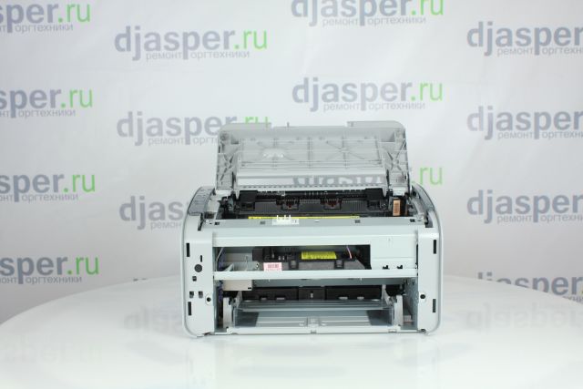
Подготовьте принтер к разборке
Откройте верхнюю крышку
Верхняя крышка
Извлеките картридж
Картридж
Ослабьте 2 защелки и снимите переднюю крышку
Защелка
Защелка
Передняя крышка
Выкрутите 3 винта
Винт
Винт
Винт
Ослабьте защелки и снимите правую крышку

Защелка
Защелка
Защелка
Ослабьте защелки и снимите левую крышку

Защелка
Защелка
Защелка
Снимите заднюю крышку
Задняя крышка
Ослабьте фиксатор и снимите верхнюю крышку
Фиксатор
Верхняя крышка
Отсоедините шлейф
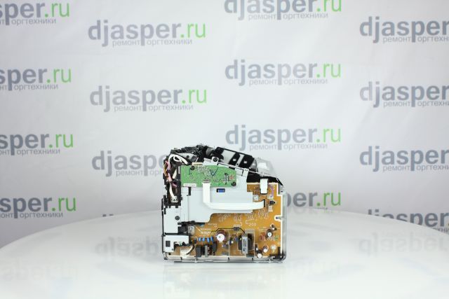
Шлейф
Выкрутите 2 винта и снимите плату форматера
Винт
Винт
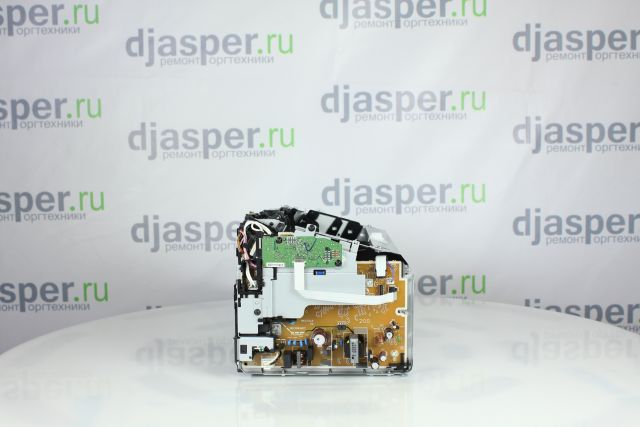
Выкрутите 3 винта и снимите металлическую пластину
Винт
Винт
Винт
Снимите черный пластиковый держатель
Пластиковый держатель
Отсоедините провод заземления
Провод заземления
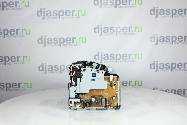
Снимите пластиковый держатель
Пластиковый держатель
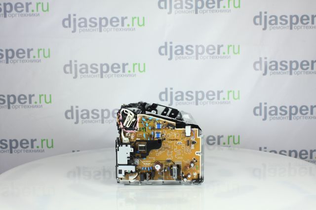
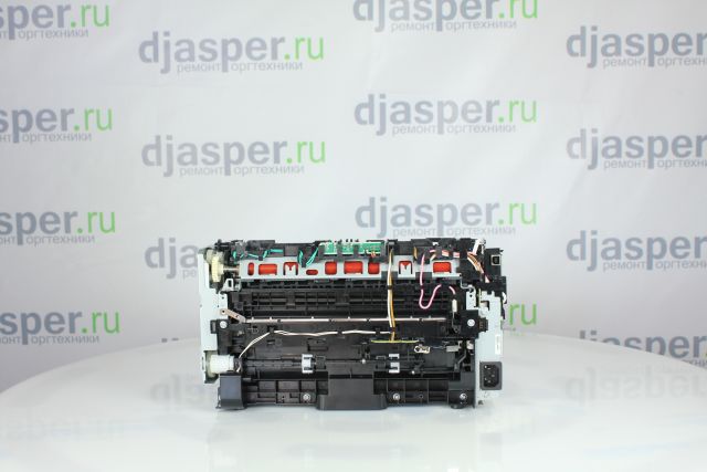
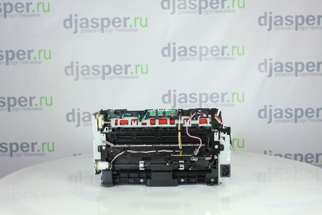
Выкрутите 3 винта и снимите печку
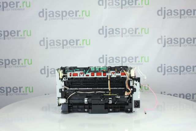
Винт
Винт
Винт
На этой странице вы сможете скачать HP LaserJet P1102 P1106 P1108 P1109 service manual в формате ПДФ. Документация содержит подробную инструкцию по разборке, обслуживанию и ремонту данного принтера и предназначена, в первую очередь, для специалистов авторизированных сервисных центров по обслуживанию печатающей техники HP.
В данном руководстве (часто его называют — repair manual) вы найдете подробную информацию по выявлению неисправностей, коды ошибок и электрические схемы устройства.
Информация:
Тип файла: PDF
Размер: 5.2 MB
Язык: EN
Количество страниц: 206
Загрузка:
Hp_LaserJet_p1102_p1106_p1108_p1109_service_manual.pdf — скачать
Сайт Printeros.RU размещает лишь прямую ссылку на инструкцию по ремонту и не имеет никакого отношения к ресурсу, публикующему данный файл.
hp-share-print-widget-portlet
![]()
Actions
- ${title}
Loading…
-
Information
Windows 7, 8, 8.1, Server 2008, 2008R2 printer drivers. End of Support.
HP no longer supports these printer drivers as of Nov 1, 2022. HP recommends upgrading your operating system to a supported version Learn more
Information
Need Windows 11 help?
Check the information on compatibility, upgrade, and available fixes from HP and Microsoft. Windows 11 Support Center
-
Feedback
![]()
LASERJET PROFESSIONAL P1100
SERIES PRINTER
Service Manual
www.hp.com/support/ljp1100series

HP LaserJet Professional P1100 Printer series
Service Manual
Copyright and License
© 2010 Copyright Hewlett-Packard
Development Company, L.P.
Reproduction, adaptation, or translation without prior written permission is prohibited, except as allowed under the copyright laws.
The information contained herein is subject to change without notice.
The only warranties for HP products and services are set forth in the express warranty statements accompanying such products and services. Nothing herein should be construed as constituting an additional warranty. HP shall not be liable for technical or editorial errors or omissions contained herein.
Part number: CE651-90953
Edition 1, 4/2010
Trademark Credits
Microsoft®, Windows®, Windows® XP, and Windows Vista® are U.S. registered trademarks of Microsoft Corporation.

Conventions used in this guide
TIP: Tips provide helpful hints or shortcuts.
 NOTE: Notes provide important information to explain a concept or to complete a task.
 CAUTION: Cautions indicate procedures that you should follow to avoid losing data or damaging the product.
 WARNING! Warnings alert you to specific procedures that you should follow to avoid personal injury, catastrophic loss of data, or extensive damage to the product.
|
iv Conventions used in this guide |
ENWW |

Table of contents
|
1 Theory of operation ………………………………………………………………………………………………………………………. |
1 |
|
Basic operation ……………………………………………………………………………………………………………………. |
2 |
|
Major product systems …………………………………………………………………………………………… |
2 |
|
Product block diagram …………………………………………………………………………………………… |
2 |
|
Sequence of operation …………………………………………………………………………………………… |
3 |
|
Normal sequence of operation …………………………………………………………………. |
3 |
|
Formatter-control system ……………………………………………………………………………………………………… |
4 |
|
Sleep mode ………………………………………………………………………………………………………….. |
4 |
|
Input/output ………………………………………………………………………………………………………….. |
4 |
|
CPU ……………………………………………………………………………………………………………………. |
4 |
|
Memory ……………………………………………………………………………………………………………….. |
4 |
|
Firmware ………………………………………………………………………………………………. |
5 |
|
Memory use ………………………………………………………………………………………….. |
5 |
|
PJL overview ……………………………………………………………………………………………………….. |
5 |
|
LEDM overview …………………………………………………………………………………………………….. |
5 |
|
ACL overview ……………………………………………………………………………………………………….. |
5 |
|
Control panel ……………………………………………………………………………………………………….. |
6 |
|
Wireless PCA ……………………………………………………………………………………………………….. |
6 |
|
Engine-control system ………………………………………………………………………………………………………….. |
7 |
|
Motors, fans, clutches, solenoids, switches, and sensors …………………………………………… |
8 |
|
DC controller operations ………………………………………………………………………………………. |
11 |
|
Fuser-control circuit …………………………………………………………………………………………….. |
12 |
|
Fuser failure detection …………………………………………………………………………… |
13 |
|
Fuser temperature control ……………………………………………………………………… |
14 |
|
Fuser protective function ……………………………………………………………………….. |
15 |
|
Pressure roller cleaning ………………………………………………………………………… |
15 |
|
Low-voltage power supply ……………………………………………………………………………………. |
16 |
|
Overcurrent/overvoltage protection …………………………………………………………. |
17 |
|
High-voltage power supply …………………………………………………………………………………… |
18 |
|
Laser/scanner system ………………………………………………………………………………………….. |
19 |
|
Laser failure detection …………………………………………………………………………… |
20 |
|
Image-formation system ……………………………………………………………………………………………………… |
21 |
|
Electrophotographic process ………………………………………………………………………………… |
21 |
|
Image formation process ……………………………………………………………………………………… |
23 |
|
Latent-image formation stage ………………………………………………………………… |
24 |
|
Primary charging …………………………………………………………………… |
24 |
|
Laser beam exposure …………………………………………………………….. |
24 |
|
Developing stage …………………………………………………………………………………. |
25 |
|
Print cartridge ……………………………………………………………………….. |
25 |
|
Transfer stage ……………………………………………………………………………………… |
26 |
|
Fusing stage …………………………………………………………………………. |
27 |
|
Cleaning stage ………………………………………………………………………. |
27 |
|
Pickup, feed, and delivery system ………………………………………………………………………………………… |
28 |
|
Photo sensors and switches …………………………………………………………………………………. |
29 |
|
Input tray, main-input tray, or priority input slot ………………………………………………………………………. |
30 |
|
Jam detection …………………………………………………………………………………………………….. |
30 |
|
2 Removal and replacement …………………………………………………………………………………………………………… |
31 |
|
Introduction ……………………………………………………………………………………………………………………….. |
32 |
|
Removal and replacement strategy ……………………………………………………………………………………… |
32 |
|
Electrostatic discharge ……………………………………………………………………………………………………….. |
33 |
|
Required tools ………………………………………………………………………………………………………………….. |
33 |
|
Before performing service …………………………………………………………………………………………………… |
34 |
|
After performing service ……………………………………………………………………………………………………… |
34 |
|
Post-service test ………………………………………………………………………………………………………………… |
35 |
|
Print-quality test ………………………………………………………………………………………………….. |
35 |
|
Parts removal order ……………………………………………………………………………………………………………. |
36 |
|
Pickup roller ………………………………………………………………………………………………………………………. |
37 |
|
Separation pad ………………………………………………………………………………………………………………….. |
38 |
|
Transfer roller ……………………………………………………………………………………………………………………. |
39 |
|
Covers ……………………………………………………………………………………………………………………………… |
40 |
|
Input tray or main-input tray ………………………………………………………………………………….. |
40 |
|
Output bin tray extension ……………………………………………………………………………………… |
41 |
|
Front cover …………………………………………………………………………………………………………. |
42 |
|
Remove the front cover …………………………………………………………………………. |
42 |
|
Left cover …………………………………………………………………………………………………………… |
43 |
|
Remove the left cover …………………………………………………………………………… |
43 |
|
Right cover …………………………………………………………………………………………………………. |
46 |
|
Remove the right cover …………………………………………………………………………. |
46 |
|
Cartridge door …………………………………………………………………………………………………….. |
48 |
|
Remove the cartridge door …………………………………………………………………….. |
48 |
|
Face-down cover ………………………………………………………………………………………………… |
50 |
|
Remove the face-down cover ………………………………………………………………… |
50 |
|
Rear cover …………………………………………………………………………………………………………. |
52 |
|
Remove the rear cover ………………………………………………………………………….. |
52 |
|
Main assemblies ………………………………………………………………………………………………………………… |
54 |
|
Formatter PCA ……………………………………………………………………………………………………. |
54 |
|
Remove the formatter PCA ……………………………………………………………………. |
55 |
|
Wireless PCA ……………………………………………………………………………………………………… |
57 |
|
Remove the wireless PCA …………………………………………………………………….. |
57 |
|
Laser/scanner assembly ………………………………………………………………………………………. |
58 |
|
Remove the laser/scanner assembly ………………………………………………………. |
58 |
|
Reinstall the laser/scanner assembly ………………………………………………………. |
60 |
|
Pickup assembly …………………………………………………………………………………………………. |
61 |
|
Remove the pickup assembly ………………………………………………………………… |
61 |
|
Reinstall the pickup assembly ………………………………………………………………… |
65 |
|
Fuser …………………………………………………………………………………………………………………. |
67 |
|
Remove the fuser …………………………………………………………………………………. |
67 |
|
Reinstall the fuser ………………………………………………………………………………… |
71 |
|
Main motor …………………………………………………………………………………………………………. |
72 |
|
Remove the main motor ………………………………………………………………………… |
72 |
|
Reinstall the main-motor drive belt ………………………………………………………….. |
76 |
|
Pickup solenoid …………………………………………………………………………………………………… |
77 |
|
Remove the pickup solenoid ………………………………………………………………….. |
77 |
|
Engine controller PCA …………………………………………………………………………………………. |
80 |
|
Remove the engine controller PCA …………………………………………………………. |
80 |
|
Reinstall the engine controller PCA ………………………………………………………… |
84 |
|
3 Solve problems …………………………………………………………………………………………………………………………… |
87 |
|
Solve problems checklist …………………………………………………………………………………………………….. |
88 |
|
Troubleshooting process …………………………………………………………………………………………………….. |
91 |
|
Determine the problem source …………………………………………………………………………….. |
91 |
|
Power subsystem ……………………………………………………………………………………………….. |
92 |
|
Power-on checks ………………………………………………………………………………….. |
92 |
|
Tools for troubleshooting …………………………………………………………………………………………………….. |
93 |
|
Individual component diagnostics ………………………………………………………………………….. |
93 |
|
Engine diagnostics ……………………………………………………………………………….. |
93 |
|
Engine-test button …………………………………………………………………. |
93 |
|
Components tests ………………………………………………………………………………… |
94 |
|
Drum rotation functional check ……………………………………………….. |
94 |
|
Half self-test functional check ………………………………………………….. |
94 |
|
Diagrams …………………………………………………………………………………………………………… |
95 |
|
Plug/jack locations ……………………………………………………………………………….. |
95 |
|
Location of connectors ………………………………………………………………………….. |
96 |
|
Locations of major components ……………………………………………………………… |
97 |
|
General timing charts ……………………………………………………………………………. |
99 |
|
General circuit diagram ……………………………………………………………………….. |
100 |
|
Internal print-quality test pages ……………………………………………………………………………. |
102 |
|
Cleaning page ……………………………………………………………………………………. |
102 |
|
Configuration page ……………………………………………………………………………… |
102 |
|
Print-quality troubleshooting tools ………………………………………………………………………… |
103 |
|
Repetitive defect ruler …………………………………………………………………………. |
103 |
|
Interpret control-panel light patterns …………………………………………………………………….. |
103 |
|
Clear jams ………………………………………………………………………………………………………………………. |
107 |
|
Common causes of jams ……………………………………………………………………………………. |
107 |
|
Jam locations ……………………………………………………………………………………………………. |
108 |
|
Clear jams from the input tray ……………………………………………………………………………… |
109 |
|
Clear jams from the output areas ………………………………………………………………………… |
111 |
|
Clear jams from inside the product ………………………………………………………………………. |
113 |
|
Solve repeated jams ………………………………………………………………………………………….. |
114 |
|
Change jam recovery ………………………………………………………………………………………… |
114 |
|
Solve paper-handling problems ………………………………………………………………………………………….. |
116 |
|
Solve image-quality problems ……………………………………………………………………………………………. |
117 |
|
Image defect table …………………………………………………………………………………………….. |
117 |
|
Light print or faded ……………………………………………………………………………… |
117 |
|
Toner specks ……………………………………………………………………………………… |
117 |
|
Dropouts ……………………………………………………………………………………………. |
118 |
|
Vertical lines ………………………………………………………………………………………. |
118 |
|
Gray background ………………………………………………………………………………… |
118 |
|
Toner smear ………………………………………………………………………………………. |
118 |
|
Loose toner ……………………………………………………………………………………….. |
119 |
|
Vertical repetitive defects …………………………………………………………………….. |
119 |
|
Misformed characters ………………………………………………………………………….. |
119 |
|
Page skew …………………………………………………………………………………………. |
119 |
|
Curl or wave ………………………………………………………………………………………. |
120 |
|
Wrinkles or creases …………………………………………………………………………….. |
120 |
|
Toner scatter outline …………………………………………………………………………… |
120 |
|
Moisture ……………………………………………………………………………………………. |
121 |
|
Optimize and improve image quality …………………………………………………………………….. |
122 |
|
Change print density …………………………………………………………………………… |
122 |
|
Clean the product …………………………………………………………………………………………………………….. |
123 |
|
Clean the pickup roller ……………………………………………………………………………………….. |
123 |
|
Clean the paper path …………………………………………………………………………………………. |
124 |
|
Clean the print-cartridge area ……………………………………………………………………………… |
126 |
|
Clean the exterior ……………………………………………………………………………………………… |
128 |
|
Solve performance problems …………………………………………………………………………………………….. |
129 |
|
Solve connectivity problems ………………………………………………………………………………………………. |
130 |
|
Solve direct-connect problems ……………………………………………………………………………. |
130 |
|
Solve wireless problems …………………………………………………………………………………….. |
130 |
|
Service mode functions …………………………………………………………………………………………………….. |
132 |
|
Product resets …………………………………………………………………………………………………… |
132 |
|
Product updates ………………………………………………………………………………………………………………. |
133 |
|
4 Parts and diagrams ……………………………………………………………………………………………………………………. |
135 |
|
Order parts by authorized service providers ………………………………………………………………………… |
136 |
|
Order parts, accessories, and supplies ………………………………………………………………… |
136 |
|
Related documentation and software …………………………………………………………………… |
136 |
|
Supplies part numbers ……………………………………………………………………………………….. |
136 |
|
Customer self repair parts ………………………………………………………………………………….. |
137 |
|
Service parts …………………………………………………………………………………………………….. |
137 |
|
Whole-unit replacement part numbers ………………………………………………………………….. |
137 |
|
How to use the parts lists and diagrams ……………………………………………………………………………… |
138 |
|
Assembly locations …………………………………………………………………………………………………………… |
139 |
|
Base product …………………………………………………………………………………………………….. |
139 |
|
Covers ……………………………………………………………………………………………………………………………. |
140 |
|
Base model ………………………………………………………………………………………………………. |
140 |
|
Wireless model …………………………………………………………………………………………………. |
142 |
|
Internal assemblies ………………………………………………………………………………………………………….. |
144 |
|
Internal assemblies (1 of 3) ………………………………………………………………………………… |
144 |
|
Internal assemblies (2 of 3) ………………………………………………………………………………… |
146 |
|
Internal assemblies (3 of 3) ………………………………………………………………………………… |
148 |
|
PCAs ……………………………………………………………………………………………………………………………… |
150 |
|
Alphabetical parts list ……………………………………………………………………………………………………….. |
152 |
|
Numerical parts list …………………………………………………………………………………………………………… |
155 |
|
Appendix A Service and support ………………………………………………………………………………………………….. |
159 |
|
Hewlett-Packard limited warranty statement ………………………………………………………………………… |
160 |
|
HP’s Premium Protection Warranty: LaserJet print cartridge limited warranty statement ……………. |
161 |
|
End User License Agreement ……………………………………………………………………………………………. |
162 |
|
Customer self-repair warranty service …………………………………………………………………………………. |
164 |
|
Customer support …………………………………………………………………………………………………………….. |
164 |
|
Repack the product ………………………………………………………………………………………………………….. |
165 |
|
Service information form …………………………………………………………………………………………………… |
166 |
|
Appendix B Specifications ……………………………………………………………………………………………………………. |
167 |
|
Physical specifications ……………………………………………………………………………………………………… |
168 |
|
Power consumption ………………………………………………………………………………………………………….. |
168 |
|
Acoustic specifications ……………………………………………………………………………………………………… |
168 |
|
Environmental specifications ……………………………………………………………………………………………… |
169 |
|
Appendix C Regulatory information ……………………………………………………………………………………………… |
171 |
|
FCC regulations ………………………………………………………………………………………………………………. |
172 |
|
Declaration of conformity (base models) ……………………………………………………………………………… |
173 |
|
Declaration of conformity (wireless models) …………………………………………………………………………. |
174 |
|
Certificate of Volatility ……………………………………………………………………………………………………….. |
175 |
|
Safety statements …………………………………………………………………………………………………………….. |
177 |
|
Laser safety ……………………………………………………………………………………………………… |
177 |
|
Canadian DOC regulations …………………………………………………………………………………. |
177 |
|
VCCI statement (Japan) …………………………………………………………………………………….. |
177 |
|
Power cord instructions ……………………………………………………………………………………… |
177 |
|
Power cord statement (Japan) …………………………………………………………………………….. |
177 |
|
EMC statement (Korea) ……………………………………………………………………………………… |
177 |
|
Laser statement for Finland ………………………………………………………………………………… |
178 |
|
GS statement (Germany) ……………………………………………………………………………………. |
178 |
|
Substances Table (China) ………………………………………………………………………………….. |
179 |
|
Additional statements for wireless products …………………………………………………………………………. |
180 |
|
FCC compliance statement—United States ………………………………………………………….. |
180 |
|
Australia statement ……………………………………………………………………………………………. |
180 |
|
Brazil ANATEL statement …………………………………………………………………………………… |
180 |
|
Canadian statements …………………………………………………………………………………………. |
180 |
|
European Union regulatory notice ……………………………………………………………………….. |
180 |
|
Notice for use in France ……………………………………………………………………………………… |
181 |
|
Notice for use in Russia ……………………………………………………………………………………… |
181 |
|
Korean statement ……………………………………………………………………………………………… |
181 |
|
Taiwan statement ……………………………………………………………………………………………… |
181 |
|
Index …………………………………………………………………………………………………………………………………………….. |
183 |

List of tables
|
Table 1-1 Sequence of operation ……………………………………………………………………………………………………….. |
3 |
|
|
Table 1-2 |
Motors ……………………………………………………………………………………………………………………………… |
8 |
|
Table 1-3 Solenoids and clutches ………………………………………………………………………………………………………. |
9 |
|
|
Table 1-4 |
Switches …………………………………………………………………………………………………………………………… |
9 |
|
Table 1-5 |
Sensors ………………………………………………………………………………………………………………………….. |
10 |
|
Table 1-6 DC controller controlled components ………………………………………………………………………………….. |
11 |
|
|
Table 1-7 Photo sensors, motor, and solenoid …………………………………………………………………………………… |
29 |
|
|
Table 3-1 Basic problem solving ………………………………………………………………………………………………………. |
88 |
|
|
Table 3-2 |
Status-light legend …………………………………………………………………………………………………………. |
103 |
|
Table 3-3 Control-panel light patterns ……………………………………………………………………………………………… |
104 |
|
|
Table 4-1 Order parts, accessories, and supplies ……………………………………………………………………………… |
136 |
|
|
Table 4-2 Related documentation and software ……………………………………………………………………………….. |
136 |
|
|
Table 4-3 Supplies part numbers ……………………………………………………………………………………………………. |
136 |
|
|
Table 4-4 Customer replaceable units (CRU) kit part numbers …………………………………………………………… |
137 |
|
|
Table 4-5 Whole-unit replacement part numbers ………………………………………………………………………………. |
137 |
|
|
Table 4-6 |
Base product …………………………………………………………………………………………………………………. |
139 |
|
Table 4-7 |
Base model …………………………………………………………………………………………………………………… |
141 |
|
Table 4-8 |
Wireless model ………………………………………………………………………………………………………………. |
143 |
|
Table 4-9 Internal assemblies (1 of 3) ……………………………………………………………………………………………… |
145 |
|
|
Table 4-10 Internal assemblies (2 of 3) ……………………………………………………………………………………………. |
147 |
|
|
Table 4-11 Internal assemblies (3 of 3) ……………………………………………………………………………………………. |
149 |
|
|
Table 4-12 |
PCAs ………………………………………………………………………………………………………………………….. |
151 |
|
Table 4-13 Alphabetical parts list ……………………………………………………………………………………………………. |
152 |
|
|
Table 4-14 Numerical parts list ……………………………………………………………………………………………………….. |
155 |
|
|
Table B-1 |
Physical specifications1 …………………………………………………………………………………………………… |
168 |
|
Table B-2 HP LaserJet Professional P1100 Printer series (average in watts)123 ……………………………………. |
168 |
|
|
Table B-3 HP LaserJet Professional P1100 Printer series12 ……………………………………………………………….. |
168 |
|
|
Table B-4 |
Environmental specifications …………………………………………………………………………………………… |
169 |

List of figures
|
Figure 1-1 Product block diagram ………………………………………………………………………………………………………. |
2 |
|
|
Figure 1-2 |
Engine-control system ………………………………………………………………………………………………………. |
7 |
|
Figure 1-3 |
Motors …………………………………………………………………………………………………………………………….. |
8 |
|
Figure 1-4 Solenoids and clutches ……………………………………………………………………………………………………… |
9 |
|
|
Figure 1-5 |
Switches …………………………………………………………………………………………………………………………. |
9 |
|
Figure 1-6 |
Sensors …………………………………………………………………………………………………………………………. |
10 |
|
Figure 1-7 DC controller block diagram ……………………………………………………………………………………………… |
11 |
|
|
Figure 1-8 Fuser control circuit …………………………………………………………………………………………………………. |
12 |
|
|
Figure 1-9 Fuser-heater control circuit ………………………………………………………………………………………………. |
14 |
|
|
Figure 1-10 Low-voltage power supply (LVPS) …………………………………………………………………………………… |
16 |
|
|
Figure 1-11 High-voltage power supply ……………………………………………………………………………………………… |
18 |
|
|
Figure 1-12 |
Laser/scanner system ……………………………………………………………………………………………………. |
19 |
|
Figure 1-13 Electrophotographic process block diagram (1 of 2) ………………………………………………………….. |
21 |
|
|
Figure 1-14 Electrophotographic process block diagram (2 of 2) ………………………………………………………….. |
22 |
|
|
Figure 1-15 Image formation process ……………………………………………………………………………………………….. |
23 |
|
|
Figure 1-16 |
Primary charging …………………………………………………………………………………………………………… |
24 |
|
Figure 1-17 Laser beam exposure ……………………………………………………………………………………………………. |
24 |
|
|
Figure 1-18 |
Print cartridge ……………………………………………………………………………………………………………….. |
25 |
|
Figure 1-19 |
Transfer ……………………………………………………………………………………………………………………….. |
26 |
|
Figure 1-20 |
Separation ……………………………………………………………………………………………………………………. |
26 |
|
Figure 1-21 |
Fusing …………………………………………………………………………………………………………………………. |
27 |
|
Figure 1-22 |
Drum cleaning ………………………………………………………………………………………………………………. |
27 |
|
Figure 1-23 Pickup, feed, and delivery system block diagram ………………………………………………………………. |
28 |
|
|
Figure 1-24 Photo sensors, motor, and solenoid ………………………………………………………………………………… |
29 |
|
|
Figure 2-1 Phillips and pozidrive screwdriver comparison ……………………………………………………………………. |
33 |
|
|
Figure 2-2 Parts removal order ………………………………………………………………………………………………………… |
36 |
|
|
Figure 2-3 Remove the pickup roller (1 of 2) ………………………………………………………………………………………. |
37 |
|
|
Figure 2-4 Remove the pickup roller (2 of 2) ………………………………………………………………………………………. |
37 |
|
|
Figure 2-5 Remove the separation pad assembly ………………………………………………………………………………. |
38 |
|
|
Figure 2-6 Remove the transfer roller ……………………………………………………………………………………………….. |
39 |
|
|
Figure 2-7 Remove the tray ……………………………………………………………………………………………………………… |
40 |
|
|
Figure 2-8 Remove the output bin tray extension ……………………………………………………………………………….. |
41 |
|
|
Figure 2-9 Remove the front cover …………………………………………………………………………………………………… |
42 |
|
|
Figure 2-10 Remove the left cover (1 of 5) …………………………………………………………………………………………. |
43 |
|
Figure 2-11 Remove the left cover (2 of 5) …………………………………………………………………………………………. |
44 |
|
Figure 2-12 Remove the left cover (3 of 5) …………………………………………………………………………………………. |
44 |
|
Figure 2-13 Remove the left cover (4 of 5) …………………………………………………………………………………………. |
45 |
|
Figure 2-14 Remove the left cover (5 of 5) …………………………………………………………………………………………. |
45 |
|
Figure 2-15 Remove the right cover (1 of 3) ………………………………………………………………………………………. |
46 |
|
Figure 2-16 Remove the right cover (2 of 3) ………………………………………………………………………………………. |
46 |
|
Figure 2-17 Remove the right cover (3 of 3) ………………………………………………………………………………………. |
47 |
|
Figure 2-18 Remove the cartridge door (1 of 2) ………………………………………………………………………………….. |
48 |
|
Figure 2-19 Remove the cartridge door (2 of 2) ………………………………………………………………………………….. |
49 |
|
Figure 2-20 Remove the face-down cover (1 of 2) ………………………………………………………………………………. |
50 |
|
Figure 2-21 Remove the face-down cover (2 of 2) ………………………………………………………………………………. |
51 |
|
Figure 2-22 Remove the rear cover (1 of 2) ……………………………………………………………………………………….. |
52 |
|
Figure 2-23 Remove the rear cover (2 of 2) ……………………………………………………………………………………….. |
53 |
|
Figure 2-24 Remove the formatter PCA (HP LaserJet Professional P1100 Printer series; 1 of 4) ……………… |
55 |
|
Figure 2-25 Remove the formatter PCA (HP LaserJet Professional P1100w Printer series; 2 of 4) …………… |
55 |
|
Figure 2-26 Remove the formatter PCA (HP LaserJet Professional P1100 Printer series; 3 of 4) ……………… |
56 |
|
Figure 2-27 Remove the formatter PCA (HP LaserJet Professional P1100w Printer series; 4 of 4) …………… |
56 |
|
Figure 2-28 Remove the wireless PCA ……………………………………………………………………………………………… |
57 |
|
Figure 2-29 Remove the laser/scanner assembly (1 of 4) ……………………………………………………………………. |
58 |
|
Figure 2-30 Remove the laser/scanner assembly (2 of 4) ……………………………………………………………………. |
59 |
|
Figure 2-31 Remove the laser/scanner assembly (3 of 4) ……………………………………………………………………. |
59 |
|
Figure 2-32 Remove the laser/scanner assembly (4 of 4) ……………………………………………………………………. |
60 |
|
Figure 2-33 Reinstall the laser/scanner assembly ………………………………………………………………………………. |
60 |
|
Figure 2-34 Remove the pickup assembly (1 of 7) ………………………………………………………………………………. |
61 |
|
Figure 2-35 Remove the pickup assembly (2 of 7) ………………………………………………………………………………. |
62 |
|
Figure 2-36 Remove the pickup assembly (3 of 7) ………………………………………………………………………………. |
62 |
|
Figure 2-37 Remove the pickup assembly (4 of 7) ………………………………………………………………………………. |
63 |
|
Figure 2-38 Remove the pickup assembly (5 of 7) ………………………………………………………………………………. |
63 |
|
Figure 2-39 Remove the pickup assembly (6 of 7) ………………………………………………………………………………. |
64 |
|
Figure 2-40 Remove the pickup assembly (7 of 7) ………………………………………………………………………………. |
64 |
|
Figure 2-41 Reinstall the pickup assembly (1 of 4; correct ground spring position) ………………………………….. |
65 |
|
Figure 2-42 Reinstall the pickup assembly (2 of 4; incorrect ground spring position) ……………………………….. |
65 |
|
Figure 2-43 Reinstall the pickup assembly (3 of 4; lift plate in raised position) ………………………………………… |
66 |
|
Figure 2-44 Reinstall the pickup assembly (4 of 4; lift plate in lowered position) ……………………………………… |
66 |
|
Figure 2-45 Remove the fuser (1 of 7) ………………………………………………………………………………………………. |
67 |
|
Figure 2-46 Remove the fuser (2 of 7) ………………………………………………………………………………………………. |
68 |
|
Figure 2-47 Remove the fuser (3 of 7) ………………………………………………………………………………………………. |
68 |
|
Figure 2-48 Remove the fuser (4 of 7) ………………………………………………………………………………………………. |
69 |
|
Figure 2-49 Remove the fuser (5 of 7) ………………………………………………………………………………………………. |
69 |
|
Figure 2-50 Remove the fuser (6 of 7) ………………………………………………………………………………………………. |
70 |
|
Figure 2-51 Remove the fuser (7 of 7) ………………………………………………………………………………………………. |
70 |
|
Figure 2-52 Reinstall the fuser; correct wire harness installation …………………………………………………………… |
71 |
|
Figure 2-53 Reinstall the fuser; incorrect wire harness installation ………………………………………………………… |
71 |
|
Figure 2-54 Remove the main motor (1 of 7) ……………………………………………………………………………………… |
72 |
|
Figure 2-55 Remove the main motor (2 of 7) ……………………………………………………………………………………… |
73 |
|
|
Figure 2-56 Remove the main motor (3 of 7) ……………………………………………………………………………………… |
73 |
|
|
Figure 2-57 Remove the main motor (4 of 7) ……………………………………………………………………………………… |
74 |
|
|
Figure 2-58 Remove the main motor (5 of 7) ……………………………………………………………………………………… |
74 |
|
|
Figure 2-59 Remove the main motor (6 of 7) ……………………………………………………………………………………… |
75 |
|
|
Figure 2-60 Remove the main motor (7 of 7) ……………………………………………………………………………………… |
75 |
|
|
Figure 2-61 Main-motor drive belt: correctly installed ………………………………………………………………………….. |
76 |
|
|
Figure 2-62 Main-motor drive belt: incorrectly installed ………………………………………………………………………… |
76 |
|
|
Figure 2-63 Remove the pickup solenoid (1 of 5) ……………………………………………………………………………….. |
77 |
|
|
Figure 2-64 Remove the pickup solenoid (2 of 5) ……………………………………………………………………………….. |
78 |
|
|
Figure 2-65 Remove the pickup solenoid (3 of 5) ……………………………………………………………………………….. |
78 |
|
|
Figure 2-66 Remove the pickup solenoid (4 of 5) ……………………………………………………………………………….. |
79 |
|
|
Figure 2-67 Remove the pickup solenoid (5 of 5) ……………………………………………………………………………….. |
79 |
|
|
Figure 2-68 Remove the engine controller PCA (1 of |
80 |
|
|
Figure 2-69 Remove the engine controller PCA (2 of |
81 |
|
|
Figure 2-70 Remove the engine controller PCA (3 of |
81 |
|
|
Figure 2-71 Remove the engine controller PCA (4 of |
82 |
|
|
Figure 2-72 Remove the engine controller PCA (5 of |
82 |
|
|
Figure 2-73 Remove the engine controller PCA (6 of |
83 |
|
|
Figure 2-74 Remove the engine controller PCA (7 of |
83 |
|
|
Figure 2-75 Remove the engine controller PCA (8 of |
84 |
|
|
Figure 2-76 Reinstall the engine controller PCA (1 of 4) ………………………………………………………………………. |
84 |
|
|
Figure 2-77 Reinstall the engine controller PCA (2 of 4) ………………………………………………………………………. |
85 |
|
|
Figure 2-78 Reinstall the engine controller PCA (3 of 4) ………………………………………………………………………. |
85 |
|
|
Figure 2-79 Reinstall the engine controller PCA (4 of 4) ………………………………………………………………………. |
86 |
|
|
Figure 3-1 Sample engine test page …………………………………………………………………………………………………. |
93 |
|
|
Figure 3-2 |
Plug/jack locations ………………………………………………………………………………………………………….. |
95 |
|
Figure 3-3 Engine controller PCA connectors …………………………………………………………………………………….. |
96 |
|
|
Figure 3-4 |
External view ………………………………………………………………………………………………………………….. |
97 |
|
Figure 3-5 Cross section view ………………………………………………………………………………………………………….. |
98 |
|
|
Figure 3-6 General timing diagram ……………………………………………………………………………………………………. |
99 |
|
|
Figure 3-7 Circuit diagram; HP LaserJet Professional P1100 Printer series …………………………………………. |
100 |
|
|
Figure 3-8 Circuit diagram; HP LaserJet Professional P1100w Printer series ……………………………………….. |
101 |
|
|
Figure 4-1 |
Base product ……………………………………………………………………………………………………………….. |
139 |
|
Figure 4-2 |
Base model ………………………………………………………………………………………………………………….. |
140 |
|
Figure 4-3 |
Wireless model …………………………………………………………………………………………………………….. |
142 |
|
Figure 4-4 Internal assemblies (1 of 3) …………………………………………………………………………………………….. |
144 |
|
|
Figure 4-5 Internal assemblies (2 of 3) …………………………………………………………………………………………….. |
146 |
|
|
Figure 4-6 Internal assemblies (3 of 3) …………………………………………………………………………………………….. |
148 |
|
|
Figure 4-7 |
PCAs …………………………………………………………………………………………………………………………… |
150 |

1 Theory of operation
●Basic operation
●Formatter-control system
●Engine-control system
●Image-formation system
●Pickup, feed, and delivery system
●Input tray, main-input tray, or priority input slot

Basic operation
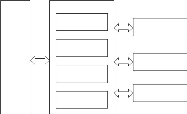
Major product systems
The product contains the following major systems:
●Engine-control system
●Laser/scanner system
●Image-formation system
●Pickup-and-feed system
Product block diagram
Figure 1-1 Product block diagram
LASER/SCANNER SYSTEM
|
ENGINE CONTROL |
IMAGE-FORMATION SYSTEM |
|
SYSTEM |
|
PICKUP-AND-FEED SYSTEM
|
2 Chapter 1 Theory of operation |
ENWW |
![]()
Sequence of operation
The DC controller in the engine-control system controls the operational sequences of the product. The table below describes durations and operations for each period of a print operation from when the prroduct is turned on until the motor stops rotating.
Normal sequence of operation
Table 1-1 Sequence of operation
|
Name |
Timing |
Purpose |
|
WAIT |
From the time the power switch is turned on, the door |
Brings the product to the ready state. The product |
|
is closed or the product exits Sleep mode until the |
performs the following during the operations: |
|
|
product gets ready for a print operation. |
● Detects the print cartridge |
|
|
● Heats the fuser film in the fuser |
||
|
● Rotates, and then stops, the main motor |
STBY (standby) From the end of the WAIT or LSTR period until either a print command is sent or the power switch is turned off.
Maintains the product in printable condition. The product performs the following during the operation:
●Enters Auto-Off mode if the Auto-Off command is received
|
INTR (initial |
From the time a print command is received until the |
|
rotation) |
paper is picked up. |
The product performs the following during the operations:
●Drives the main motor
●Activates the high-voltage power supply
●Activates the laser/scanner
●Warms the fuser heater
|
|
From the end of the INTR period until the last sheet |
|
completes the fuser operation. |
Forms the image on the photosensitive drum based on the VIDEO signals from the formatter. Transfers and fuses the toner image to the paper.
|
LSTR (last |
From the end of the PRINT period until the main motor |
|
rotation) |
stops rotating. |
Moves the last printed sheet out of the product. The product performs the following during the operations:
●Stops the main motor
●Deactivates the high-voltage power supply
●Deactivates the laser/scanner
●Deactivates the fuser heater
The product enters the INTR period as the LSTR period is completed, if the formatter sends another print command.

Formatter-control system
The formatter is responsible for the following procedures:
●Controlling sleep mode
●Receiving and processing print data from the various product interfaces
●Monitoring control-panel functions and relaying product-status information (through the control panel and the network or bidirectional interface)
●Developing and coordinating data placement and timing with the DC controller PCA
●Storing font information
●Communicating with the host computer through the network or the bidirectional interface
The formatter receives a print job from the network or bidirectional interface and separates it into image information and instructions that control the printing process. The DC controller PCA synchronizes the image-formation system with the paper-input and -output systems, and then signals the formatter to send the print-image data.
Sleep mode
 NOTE: This product uses an Auto-Off feature for sleep mode.
After a user-specified time, the Auto-Off feature automatically conserves electricity by substantially reducing power consumption when the product is not printing. After a user-specified time, the product automatically reduces its power consumption (Auto-Off). The product returns to the ready state when a button is pressed, a print job is received, or a door is opened. When the product is in Auto-Off mode, the control-panel LEDs and the power button backlight LED are off.
 NOTE: Although the product lights are off in Auto-Off mode, the product functions normally when it receives a print job.
Input/output
The product receives print data primarily from the following:
●Hi-Speed USB 2.0 port
●802.11b/g wireless networking (wireless models only)
CPU
The formatter incorporates a 400 MHz Helium processor.
Memory
The random access memory (RAM) on the formatter PCA contains the page, I/O buffers, and the font storage area. RAM stores printing and font information received from the host system, and can also serve to temporarily store a full page of print-image data before the data is sent to the print engine.
|
4 Chapter 1 Theory of operation |
ENWW |

Firmware
●HP LaserJet Professional P1100 Printer series
◦The product has 2 MB of Synchronous DRAM, which is used for run-time firmware imaging and specific print job information for the print job.
●HP LaserJet Professional P1100w Printer series
◦The product has 8 MB of Synchronous DRAM, which is used for run-time firmware imaging and specific print job information for the print job.
Memory use
●HP LaserJet Professional P1100 Printer series
◦The product has a 2 KB EEPROM and 64 MB of NAND Flash Memory, which is used for product configuration information and printer driver firmware.
●HP LaserJet Professional P1100w Printer series
◦The product has a 8 KB EEPROM and 64 MB of NAND Flash Memory, which is used for product configuration information and printer driver firmware.
PJL overview
The printer job language (PJL) is an integral part of configuration, in addition to the standard printer command language (PCL). With standard cabling, the product can use PJL to perform a variety of functions such as these:
●Two-way communication with the host computer through a network connection or a USB connection. The product can inform the host about such things as the control-panel settings, and the control-panel settings can be changed from the host.
●Dynamic I/O switching. The product uses this switching to be configured with a host on each I/O. The product can receive data from more than one I/O simultaneously, until the I/O buffer is full. This can occur even when the product is offline.
●Context-sensitive switching. The product can automatically recognize the personality (PS or PCL) of each job and configure itself to serve that personality.
●Isolation of print environment settings from one print job to the next. For example, if a print job is sent to the product in landscape mode, the subsequent print jobs print in landscape mode only if they are formatted for landscape printing.
LEDM overview
 NOTE: HP LaserJet Professional P1100w Printer series
The low-end data model (LEDM) provides one consistent data representation method and defines the dynamic and capabilities tickets shared between clients and devices, as well as the access protocol, event, security, and discovery methods.
ACL overview
The advanced control language (ACL) is a language that supports product control and firmware downloads in products that support both PJL/PCL and host-based printing. Each sequence of ACL
|
ENWW |
Formatter-control system 5 |

commands must be preceded by a unified exit command (UEL) and an @PJL ENTER LANGUAGE=ACL command. The ACL sequence is always followed by a UEL. Any number of commands can be placed between the UELs. The only exception to these rules is the download command. If a firmware download is done, the download command must be the last command in the sequence. It will not be followed by a UEL.
The firmware searches for the UEL sequence when parsing commands. However, while downloading binary data such as host-based code or NVRAM data the firmware suspends UEL parsing. To handle hosts that “disappear” during binary sequences, the firmware times out all ACL command sessions. If a timeout occurs during a non-download command sequence, it is treated as the receipt of a UEL. If a timeout occurs during firmware download the product resets.
Control panel
The formatter sends and receives product status and command data to and from the control-panel PCA.
Wireless PCA
 NOTE: Wireless models only.
The wireless PCA controls the wireless function of the product
|
6 Chapter 1 Theory of operation |
ENWW |
Engine-control system
The engine-control system coordinates all product functions, according to commands that the formatter sends. The engine-control system drives the laser/scanner system, the image-formation system, and the pickup/feed/delivery system.
The engine control system contains the following major components:
●Engine-control unit (ECU)
◦DC controller
◦Low-voltage power supply
●High-voltage power supply
●Fuser control
Figure 1-2 Engine-control system
ENGINE CONTROL SYSTEM
DC controller
Low-voltage power supply
LASER/SCANNER SYSTEM
|
Formatter |
IMAGE-FORMATION SYSTEM |
High-voltage power supply
MEDIA-FEED SYSTEM
Fuser control
|
ENWW |
Engine-control system 7 |
Motors, fans, clutches, solenoids, switches, and sensors
Figure 1-3 Motors
M1
M2
Table 1-2 Motors
|
Description |
Components driven |
|
|
Main motor (M1) |
● |
Pickup roller |
|
● |
Feed roller |
|
|
● |
Photosensitive drum |
|
|
● |
Developing roller |
|
|
● |
Pressure roller |
|
|
● |
Delivery roller |
|
|
Scanner motor (M2) |
● |
Scanner mirror |
|
8 Chapter 1 Theory of operation |
ENWW |

Figure 1-4 Solenoids and clutches
SL1
Table 1-3 Solenoids and clutches
|
Item |
Description |
|
SL1 |
Pickup solenoid |
Figure 1-5 Switches
Table 1-4 Switches
|
Item |
Description |
|
SW501 |
Cartridge-door switch |
|
SW502 |
Power switch; not shown |
|
ENWW |
Engine-control system 9 |

|
Figure 1-6 |
Sensors |
|
PS702 |
|
|
PS701 |
|
|
Single-sheet-feed slot |
|
|
(HP LJP P1100w printer Series) |
|
|
PS751 |
|
|
Table 1-5 Sensors |
|
|
Item |
Description |
|
PS701 |
Fuser delivery sensor |
|
PS702 |
Media width sensor |
|
PS751 |
Top-of-Page (TOP) sensor |
|
PS901 |
Main-motor rotation-number sensor; not shown |
|
10 Chapter 1 Theory of operation |
ENWW |

DC controller operations
The DC controller controls the operational sequences of the product systems.
Figure 1-7 DC controller block diagram
|
Engine controller |
||
|
AC input |
||
|
Low-voltage |
Motor |
|
|
power supply |
||
|
Fuser unit |
||
|
Solenoid |
||
|
Transfer roller |
Photointerrupter |
|
|
DC controller |
||
|
Cartridge |
High-voltage |
|
|
power supply |
||
|
Switch |
||
Laser scanner
Formatter
Operation panel
Table 1-6 DC controller controlled components
|
Component |
Designator |
Description |
|
Motor |
M1 |
Main motor |
|
M2 |
Scanner motor |
|
|
Solenoid |
SL1 |
Pickup solenoid |
|
Photointerrupter |
PS701 |
Fuser delivery sensor |
|
PS702 |
Media width sensor |
|
|
PS751 |
Top-of-Page (TOP) sensor |
|
|
PS901 |
Main-motor rotation-number sensor |
|
|
ENWW |
Engine-control system 11 |

Table 1-6 DC controller controlled components (continued)
|
Component |
Designator |
Description |
|
Switch |
SW501 |
Cartridge-door switch |
|
SW502 |
Power switch |
|
Fuser-control circuit
The fuser-control circuit monitors and controls the temperature in the fuser. The product uses ondemand fusing. The fuser-control circuit consists of the following major components:
●Fuser heater (H1); heats the fusing film
●Thermistor (TH1); detects the fuser temperature (contact type)
●Thermal fuse (FU1); prevents abnormal temperature rise in the fuser (contact type)
Figure 1-8 Fuser control circuit
Fuser film
TH1
FU1
 Pressure roller
H1
FUSER TEMPERATURE signal
FUSER HEATER CONTROL signal
|
Fuser heater control |
Fuser heater safety |
|
circuit |
circuit |
|
Fuser control |
DC controller |
|
Engine controller |
|
12 Chapter 1 Theory of operation |
ENWW |
Fuser failure detection
The DC controller determines a fuser unit failure, releases the relay to interrupt power supply to the fuser heater, and notifies the formatter of a failure state when it encounters the following conditions:
●Start up failure
◦If the main thermistor does not detect a specified temperature during the start up process of the heater in the wait period.
◦If the main thermistor does not detect a specified temperature during the heater temperature control in the initial rotation period.
●Abnormal low temperature
◦If the main thermistor detects an abnormal low temperature of the fuser unit during the printing operation.
●Abnormal high temperature
◦If the main thermistor detects an abnormal high temperature of the fuser unit.
●Frequency detection circuit failure
◦If a specified frequency of the FREQUENCY signal is not detected within a specified period after the product is turned on.
|
ENWW |
Engine-control system 13 |

Fuser temperature control
The fuser temperature control maintains the temperature of the fuser heater at its targeted temperature.
The DC controller monitors the FIXING TEMPERATURE (FSRTH) signals and sends the FIXING HEATER CONTROL (FSRD) signal according to the detected temperature. The fuser heater control circuit controls the fuser heater depending on the signal so that the heater remains at the targeted temperature.
Figure 1-9 Fuser-heater control circuit
AC input 


|
Fixing control |
|||
|
Frequency detection |
FREQSNS |
||
|
circuit |
|||
|
(220-240V model only) |
|||
|
RL101 |
Relay control |
Fuser heater |
RLYD |
|
circuit |
safety circuit |
||
|
Fuser heater |
FSRD |
||
|
control circuit |
|||
|
FSRTH |
|||
|
FU1 |
TH1 |
||
|
H1 |
Fuser film unit
Engine controller
DC controller
Pressure roller
Fuser unit
|
14 Chapter 1 Theory of operation |
ENWW |
Fuser protective function
The protective function detects an abnormal temperature rise of the fuser unit and interrupts power supply to the fuser heater.
The following three protective components prevent an abnormal temperature rise of the fuser heater:
●DC controller
◦The DC controller interrupts power supply to the fuser heater when it detects an abnormal temperature of the fuser heater.
●Fuser heater safety circuit
◦The fuser heater safety circuit interrupts power supply to the fuser heater when the detected temperature of the main thermistor is abnormal.
●Thermal fuse
◦The contact of the thermal fuse is broken to interrupt power supply to the fuser heater when the thermal fuse detects an abnormal temperature of the fuser heater.
Pressure roller cleaning
The pressure roller cleaning process is initiated by the formatter. The process removes toner that has accumulated on the pressure roller by transferring it to a sheet of paper.
●The product feeds a sheet of paper after receiving the cleaning command from the formatter.
●Main motor rotation is stopped when the trailing edge of the paper passes through the transfer roller.
●The main motor rotation is repeatedly started and then stopped. The fuser heater is turned on and then off at the same interval as main motor rotation.
●Toner adhered to the pressure roller is fused to the paper.
●The paper is ejected from the product.
|
ENWW |
Engine-control system 15 |

Low-voltage power supply
The low-voltage power supply (LVPS) converts ac input voltage to dc voltage. The LVPS has two fuses on the PCA. The LVPS 24 V output is interrupted to the fuser and the high-voltage power supply if the cartridge-door interlock switch (SW501) is in the off position (cover open).
 WARNING! The product power switch only interrupts dc voltage from the LVPS. The ac voltage is present in the product when the power cord is plugged into a power receptacle and the power switch is in the off position. You must unplug the product power cord before servicing the product.
Figure 1-10 Low-voltage power supply (LVPS)
AC input
|
Engine controller |
|||
|
Low-voltage power supply |
DC controller |
||
|
Fuser unit |
|||
|
Fuse (FU101) |
|||
|
Fuse (FU201) |
|||
|
Cartridge-door switch |
High-voltage |
||
|
(SW501) |
power supply |
||
|
+24U |
|||
|
Rectifying |
|||
|
circuit |
|||
|
Frequency |
FREQSNS |
||
|
detection circuit |
|||
|
(220-240V model only) |
|||
|
+24V |
BSTSIG |
||
|
generation |
+24V |
||
|
circuit |
|||
|
+24V ON/OFF |
24VON |
||
|
+24P |
|||
|
circuit |
|||
|
+5V |
+5V |
||
|
Protection |
generation |
||
|
+5R |
|||
|
circuit |
circuit |
||
|
+3.3V |
+3.3V |
||
|
generation |
|||
|
circuit |
|||
|
+3.3VON |
|||
|
+3.3V ON/OFF |
+3.3UON |
||
|
circuit |
+3.3U |
||
|
+3.3R |
|||
|
Formatter |
Power switch |
||
|
(SW502) |
|
16 Chapter 1 Theory of operation |
ENWW |

Overcurrent/overvoltage protection
The low-voltage power supply has a protective function against overcurrent and overvoltage to prevent failures in the power supply circuit. If an overcurrent or overvoltage condition occurs, the system automatically cuts off the output voltage.
If the dc power is not being supplied from the low-voltage power supply, the protective function might be running. In such case, turn off the power switch and unplug the power cord. Do not plug in the power cord or turn on the power switch again until the cause is found.
 WARNING! If you believe the overcurrent or overvoltage protection circuits have been activated, do not plug in the product power cord or turn on the product power until the cause of the failure is found and corrected.
In addition, two fuses in the low-voltage power supply protect against overcurrent. If overcurrent flows into the ac line, the fuses melt and cut off the power distribution.
|
ENWW |
Engine-control system 17 |

High-voltage power supply
The high-voltage power supply (HVPS) applies biases to the following components:
●Primary charging roller
●Developing roller
●Transfer roller
Figure 1-11 High-voltage power supply
Engine controller
|
DC controller |
High-voltage power supply |
Primary charging bias circuit
 To primary charging roller
Developing To developing roller bias circuit
Cartridge
|
Transfer bias |
Photosensitive drum |
|
circuit |
Transfer roller |
|
18 Chapter 1 Theory of operation |
ENWW |

Laser/scanner system
The laser/scanner system receives VIDEO signals from the ECU and formatter and converts the signals into latent images on the photosensitive drum.
The main components of the laser/scanner are the laser unit and the scanner motor unit. The DC controller sends signals to the laser/scanner to control the functions of these components.
Figure 1-12 Laser/scanner system
|
BD sensor |
Photosensitive drum |
Laser unit
Scanning mirror
Scanner motor unit
|
BDI signal |
VIDEO signal |
LASER CONTROL signal |
SCANNER MOT OR CONTROL signal |
|
DC controller |
|||
|
Engine controller |
|||
|
Formatter |
|
ENWW |
Engine-control system 19 |
Laser failure detection
The DC controller determines an optical unit failure and notifies the formatter, if the laser/scanner encounters the following conditions:
●The scanner motor does not reach a specified rotation within a specified period of the scanner motor start up.
●The rotation of the scanner motor is out of specified range for a specified period during the scanner motor drive.
●The BD interval is out of a specified value during a print operation.
|
20 Chapter 1 Theory of operation |
ENWW |

Image-formation system
Electrophotographic process
The electrophotographic process forms an image on the paper. Following are the major components used in the process:
●Print cartridge
●Transfer roller
●Fuser
●Laser/scanner
●High-voltage power supply
The DC controller uses the laser/scanner and HVPS to form the toner image on the photosensitive drum. The image is transferred to the paper and then fused onto the paper.
Figure 1-13 Electrophotographic process block diagram (1 of 2)
Transfer roller
Cartridge
Laser scanner
High-voltage power supply
DC controller
Engine controller
The DC controller rotates the main motor to drive the following components:
●Photosensitive drum
●Developing drum
●Primary charging roller (follows the rotation of the photosensitive drum)
●Transfer roller (follows the rotation of the photosensitive drum)
|
ENWW |
Image-formation system 21 |

Figure 1-14 Electrophotographic process block diagram (2 of 2)
|
Primary charging roller |
|
|
Developing roller |
Main motor |
Cartridge
Transfer roller
Photosensitive drum
DC controller
Engine controller
|
22 Chapter 1 Theory of operation |
ENWW |
![]()
Image formation process
Each of the following process function independently and must be coordinated with the other product processes. Image formation consists of the following processes:
●Latent-image formation block
◦Step 1: primary charging
◦Step 2: laser-beam exposure
●Developing block
◦Step 3: developing
●Transfer block
◦Step 4: transfer
◦Step 5: separation
●Fusing block
◦Step 6: fusing
●Drum cleaning block
◦Step 7: drum cleaning
Figure 1-15 Image formation process
|
ENWW |
Image-formation system 23 |

Latent-image formation stage
During the latent-image formation stage, the laser/scanner forms an invisible image on the photosensitive drum in the print cartridge.
Primary charging
Step 1: dc and ac biases are applied to the primary charging roller, which transfers a uniform negative potential to the photosensitive drum.
Figure 1-16 Primary charging
Primary charging roller
DC bias
Photosensitive drum
Laser beam exposure
Step 2: The laser beam scans the photosensitive drum to neutralize negative charges on parts of the drum surface. An electrostatic latent image is formed on the drum where negative charges were neutralized.
Figure 1-17 Laser beam exposure
Laser beam
|
Unexposed area |
Exposed area |
||||||||||||||
|
24 Chapter 1 Theory of operation |
ENWW |

Developing stage
Print cartridge
Step 3: In the print cartridge, the developing cylinder transfers toner onto the electrostatic latent image on the photosensitive drum.
Figure 1-18 Print cartridge
|
Blade |
||
|
Developing cylinder |
||
|
Exposed area |
Unexposed area |
AC bias |
|
Unexposed area |
Exposed area |
|
|
DC bias |
Photosensitive drum
Toner acquires a negative charge from the friction that occurs when the developing roller rotates against the developing blade. The developing bias is applied to the developing roller to make a potential difference between the developing roller and the photosensitive drum. The negatively charged toner is attracted to the latent image on the photosensitive drum because the drum surface has a higher potential.
|
ENWW |
Image-formation system 25 |

Transfer stage
Step 4: The transfer charging roller, to which a DC positive bias is applied, imparts a positive charge on the paper. When the paper comes in contact with the photosensitive drum, the toner is transferred to the paper.
Figure 1-19 Transfer
Photosensitive
drum
Media
Transfer roller
DC bias
Step 5: The elasticity of the paper causes its separation from the photosensitive drum. A static charge eliminator aids separation by weakening any electrostatic adhesion.
Figure 1-20 Separation
Photosensitive
drum
Media
Static charge eliminator
Transfer roller
|
26 Chapter 1 Theory of operation |
ENWW |

Fusing stage
Step 6: The DC negative bias applied to the fusing film strengthens the holding force of the toner on the paper and prevents the toner from scattering.
The product uses an on-demand fuser method. The toner image is permanently affixed to the paper by heat and pressure.
Figure 1-21 Fusing
Fuser heater
Fuser film
Toner
Media
Pressure roller
Cleaning stage
Step 7: The cleaning blade scrapes the residual toner off of the photosensitive drum and deposits it into the waste toner case.
Figure 1-22 Drum cleaning
Cleaning blade
 Photosensitive
|
Waste toner container |
drum |
|
ENWW |
Image-formation system 27 |

Pickup, feed, and delivery system
The media feed system picks up, feeds, and delivers the page.
Figure 1-23 Pickup, feed, and delivery system block diagram
Delivery roller
|
Pressure roller |
||
|
Fuser film |
||
|
Transfer roller |
||
|
Photosensitive drum |
Single-sheet-feed slot |
|
|
(HP LJP P1100w printer Series) |
||
Feed roller
Pickup roller
Separation pad
|
28 Chapter 1 Theory of operation |
ENWW |

Photo sensors and switches
 NOTE: The illustration in this section also shows the product motor and solenoid. The power switch is not shown.
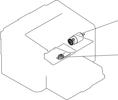
Figure 1-24 Photo sensors, motor, and solenoid
PS702
PS701
M1
 PS751
PS751
Single-sheet-feed slot
(HP LJP P1100w printer Series)
Table 1-7 Photo sensors, motor, and solenoid
|
Item |
Description |
|
M1 |
Main motor |
|
SL1 |
Pickup solenoid |
|
PS701 |
Fuser delivery sensor |
|
PS702 |
Media-width sensor |
|
PS751 |
TOP sensor |
|
ENWW |
Pickup, feed, and delivery system 29 |

Input tray, main-input tray, or priority input slot
 NOTE: The HP LaserJet Professional P1100 Printer series has a single input tray. The HP LaserJet Professional P1100w Printer series has a main-input tray and a priority input slot.
Jam detection
The product uses the following sensors to detect the presence of paper and to check for jams. The paper must pass each sensor within a specified time.
 NOTE: To find the following components, see Photo sensors and switches on page 29.
●PS701; fuser delivery sensor
●PS702; TOP sensor
 NOTE: The product automatically ejects paper if the TOP sensor detects residual paper within the product when the power is turned on or the door is closed.
The product detects the following jams:
●Pickup stationary jam
●Delivery delay jam
●Delivery stationary jam
●Fuser wrapping jam
●Door open jam
●Residual media jam
|
30 Chapter 1 Theory of operation |
ENWW |

2 Removal and replacement
●Introduction
●Removal and replacement strategy
●Electrostatic discharge
●Required tools
●Before performing service
●After performing service
●Post-service test
●Parts removal order
●Pickup roller
●Separation pad
●Transfer roller
●Covers
●Main assemblies

Introduction
This chapter describes the removal and replacement of field-replaceable units (FRUs) only.
Replacing FRUs is generally the reverse of removal. Occasionally, notes and tips are included to provide directions for difficult or critical replacement procedures.
HP does not support repairing individual subassemblies or troubleshooting to the component level.
Note the length, diameter, color, type, and location of each screw. Be sure to return each screw to its original location during reassembly.
Incorrectly routed or loose wire harnesses can interfere with other internal components and can become damaged or broken. Frayed or pinched harness wires can be difficult to find. When replacing wire harnesses, always use the provided wire loops, lance points, or wire-harness guides and retainers.
Removal and replacement strategy
 WARNING! Turn the product off, wait 5 seconds, and then remove the power cord before attempting to service the product. If this warning is not followed, severe injury can result, in addition to damage to the product. The power must be on for certain functional checks during troubleshooting. However, disconnect the power supply during parts removal.
Never operate or service the product with the protective cover removed from the laser/scanner assembly. The reflected beam, although invisible, can damage your eyes.
The sheet-metal parts can have sharp edges. Be careful when handling sheet-metal parts.
 CAUTION: Do not bend or fold the flat flexible cables (FFCs) during removal or installation. Also, do not straighten pre-folds in the FFCs. You must fully seat all FFCs in their connectors. Failure to fully seat an FFC into a connector can cause a short circuit in a PCA.
 NOTE: To install a self-tapping screw, first turn it counterclockwise to align it with the existing thread pattern, and then carefully turn it clockwise to tighten. Do not overtighten. If a self-tapping screw-hole becomes stripped, repair the screw-hole or replace the affected assembly.
TIP: For clarity, some photos in this chapter show components removed that would not be removed to service the product. If necessary, remove the components listed at the beginning of a procedure before proceeding to service the product.
|
32 Chapter 2 Removal and replacement |
ENWW |
 Loading…
 Contents:
1. Theory of operation;
Basic operation;
Formatter-control system;
Engine-control system;
Image-formation system;
Pickup, feed, and delivery system;
Input tray, main-input tray, or priority input slot;
2. Removal and replacement;
3. Solve problems;
4. Parts and diagrams;
Appendix A. Service and support;
Appendix B. Specifications;
Appendix C. Regulatory information;
Index.
Download HP LaserJet P1100 Series Printer. Service Manual
Formatter-control system HP P1100 P1102
The formatter is responsible for the following procedures:
- Controlling sleep mode
- Receiving and processing print data from the various product interfaces
- Monitoring control-panel functions and relaying product-status information (through the control panel and the network or bidirectional interface)
- Developing and coordinating data placement and timing with the DC controller PCA
- Storing font information
- Communicating with the host computer through the network or the bidirectional interface
The formatter receives a print job from the network or bidirectional interface and separates it into image information and instructions that control the printing process. The DC controller PCA synchronizes the image-formation system with the paper-input and -output systems, and then signals the formatter to send the print-image data.
Read More HP P1100 P1102 Service Manual on PDF Below

Перейти к содержанию
На чтение 1 мин Просмотров 10

На этой странице вы сможете скачать HP LaserJet P1102 P1106 P1108 P1109 service manual в формате ПДФ. Документация содержит подробную инструкцию по разборке, обслуживанию и ремонту данного принтера и предназначена, в первую очередь, для специалистов авторизированных сервисных центров по обслуживанию печатающей техники HP.
В данном руководстве (часто его называют repair manual) вы найдете подробную информацию по выявлению неисправностей, коды ошибок и электрические схемы устройства.
Информация:
Тип файла: PDF Размер: 5.2 MB Язык: EN Количество страниц: 206
Загрузка:
Hp_LaserJet_p1102_p1106_p1108_p1109_service_manual.pdf скачать
Сайт Printeros.RU размещает лишь прямую ссылку на инструкцию по ремонту и не имеет никакого отношения к ресурсу, публикующему данный файл.

Серия принтеров
LASERJET PROFESSIONAL
P1100
Руководство пользователя
www.hp.com/support/ljp1100series
![]()
LASERJET PROFESSIONAL P1100
SERIES PRINTER
Service Manual
www.hp.com/support/ljp1100series
HP LaserJet Professional P1100 Printer series
Service Manual
Copyright and License
© 2010 Copyright Hewlett-Packard
Development Company, L.P.
Reproduction, adaptation, or translation without prior written permission is prohibited, except as allowed under the copyright laws.
The information contained herein is subject to change without notice.
The only warranties for HP products and services are set forth in the express warranty statements accompanying such products and services. Nothing herein should be construed as constituting an additional warranty. HP shall not be liable for technical or editorial errors or omissions contained herein.
Part number: CE651-90953
Edition 1, 4/2010
Trademark Credits
Microsoft®, Windows®, Windows® XP, and Windows Vista® are U.S. registered trademarks of Microsoft Corporation.
Conventions used in this guide
TIP: Tips provide helpful hints or shortcuts.
NOTE: Notes provide important information to explain a concept or to complete a task.
CAUTION: Cautions indicate procedures that you should follow to avoid losing data or damaging the product.
WARNING! Warnings alert you to specific procedures that you should follow to avoid personal injury, catastrophic loss of data, or extensive damage to the product.
|
iv Conventions used in this guide |
ENWW |
Table of contents
|
1 Theory of operation ………………………………………………………………………………………………………………………. |
1 |
|
Basic operation ……………………………………………………………………………………………………………………. |
2 |
|
Major product systems …………………………………………………………………………………………… |
2 |
|
Product block diagram …………………………………………………………………………………………… |
2 |
|
Sequence of operation …………………………………………………………………………………………… |
3 |
|
Normal sequence of operation …………………………………………………………………. |
3 |
|
Formatter-control system ……………………………………………………………………………………………………… |
4 |
|
Sleep mode ………………………………………………………………………………………………………….. |
4 |
|
Input/output ………………………………………………………………………………………………………….. |
4 |
|
CPU ……………………………………………………………………………………………………………………. |
4 |
|
Memory ……………………………………………………………………………………………………………….. |
4 |
|
Firmware ………………………………………………………………………………………………. |
5 |
|
Memory use ………………………………………………………………………………………….. |
5 |
|
PJL overview ……………………………………………………………………………………………………….. |
5 |
|
LEDM overview …………………………………………………………………………………………………….. |
5 |
|
ACL overview ……………………………………………………………………………………………………….. |
5 |
|
Control panel ……………………………………………………………………………………………………….. |
6 |
|
Wireless PCA ……………………………………………………………………………………………………….. |
6 |
|
Engine-control system ………………………………………………………………………………………………………….. |
7 |
|
Motors, fans, clutches, solenoids, switches, and sensors …………………………………………… |
8 |
|
DC controller operations ………………………………………………………………………………………. |
11 |
|
Fuser-control circuit …………………………………………………………………………………………….. |
12 |
|
Fuser failure detection …………………………………………………………………………… |
13 |
|
Fuser temperature control ……………………………………………………………………… |
14 |
|
Fuser protective function ……………………………………………………………………….. |
15 |
|
Pressure roller cleaning ………………………………………………………………………… |
15 |
|
Low-voltage power supply ……………………………………………………………………………………. |
16 |
|
Overcurrent/overvoltage protection …………………………………………………………. |
17 |
|
High-voltage power supply …………………………………………………………………………………… |
18 |
|
Laser/scanner system ………………………………………………………………………………………….. |
19 |
|
Laser failure detection …………………………………………………………………………… |
20 |
|
Image-formation system ……………………………………………………………………………………………………… |
21 |
|
Electrophotographic process ………………………………………………………………………………… |
21 |
|
Image formation process ……………………………………………………………………………………… |
23 |
|
Latent-image formation stage ………………………………………………………………… |
24 |
|
Primary charging …………………………………………………………………… |
24 |
|
Laser beam exposure …………………………………………………………….. |
24 |
|
Developing stage …………………………………………………………………………………. |
25 |
|
Print cartridge ……………………………………………………………………….. |
25 |
|
Transfer stage ……………………………………………………………………………………… |
26 |
|
Fusing stage …………………………………………………………………………. |
27 |
|
Cleaning stage ………………………………………………………………………. |
27 |
|
Pickup, feed, and delivery system ………………………………………………………………………………………… |
28 |
|
Photo sensors and switches …………………………………………………………………………………. |
29 |
|
Input tray, main-input tray, or priority input slot ………………………………………………………………………. |
30 |
|
Jam detection …………………………………………………………………………………………………….. |
30 |
|
2 Removal and replacement …………………………………………………………………………………………………………… |
31 |
|
Introduction ……………………………………………………………………………………………………………………….. |
32 |
|
Removal and replacement strategy ……………………………………………………………………………………… |
32 |
|
Electrostatic discharge ……………………………………………………………………………………………………….. |
33 |
|
Required tools ………………………………………………………………………………………………………………….. |
33 |
|
Before performing service …………………………………………………………………………………………………… |
34 |
|
After performing service ……………………………………………………………………………………………………… |
34 |
|
Post-service test ………………………………………………………………………………………………………………… |
35 |
|
Print-quality test ………………………………………………………………………………………………….. |
35 |
|
Parts removal order ……………………………………………………………………………………………………………. |
36 |
|
Pickup roller ………………………………………………………………………………………………………………………. |
37 |
|
Separation pad ………………………………………………………………………………………………………………….. |
38 |
|
Transfer roller ……………………………………………………………………………………………………………………. |
39 |
|
Covers ……………………………………………………………………………………………………………………………… |
40 |
|
Input tray or main-input tray ………………………………………………………………………………….. |
40 |
|
Output bin tray extension ……………………………………………………………………………………… |
41 |
|
Front cover …………………………………………………………………………………………………………. |
42 |
|
Remove the front cover …………………………………………………………………………. |
42 |
|
Left cover …………………………………………………………………………………………………………… |
43 |
|
Remove the left cover …………………………………………………………………………… |
43 |
|
Right cover …………………………………………………………………………………………………………. |
46 |
|
Remove the right cover …………………………………………………………………………. |
46 |
|
Cartridge door …………………………………………………………………………………………………….. |
48 |
|
Remove the cartridge door …………………………………………………………………….. |
48 |
|
Face-down cover ………………………………………………………………………………………………… |
50 |
|
Remove the face-down cover ………………………………………………………………… |
50 |
|
Rear cover …………………………………………………………………………………………………………. |
52 |
|
Remove the rear cover ………………………………………………………………………….. |
52 |
|
Main assemblies ………………………………………………………………………………………………………………… |
54 |
|
Formatter PCA ……………………………………………………………………………………………………. |
54 |
|
Remove the formatter PCA ……………………………………………………………………. |
55 |
|
Wireless PCA ……………………………………………………………………………………………………… |
57 |
|
Remove the wireless PCA …………………………………………………………………….. |
57 |
|
Laser/scanner assembly ………………………………………………………………………………………. |
58 |
|
Remove the laser/scanner assembly ………………………………………………………. |
58 |
|
Reinstall the laser/scanner assembly ………………………………………………………. |
60 |
|
Pickup assembly …………………………………………………………………………………………………. |
61 |
|
Remove the pickup assembly ………………………………………………………………… |
61 |
|
Reinstall the pickup assembly ………………………………………………………………… |
65 |
|
Fuser …………………………………………………………………………………………………………………. |
67 |
|
Remove the fuser …………………………………………………………………………………. |
67 |
|
Reinstall the fuser ………………………………………………………………………………… |
71 |
|
Main motor …………………………………………………………………………………………………………. |
72 |
|
Remove the main motor ………………………………………………………………………… |
72 |
|
Reinstall the main-motor drive belt ………………………………………………………….. |
76 |
|
Pickup solenoid …………………………………………………………………………………………………… |
77 |
|
Remove the pickup solenoid ………………………………………………………………….. |
77 |
|
Engine controller PCA …………………………………………………………………………………………. |
80 |
|
Remove the engine controller PCA …………………………………………………………. |
80 |
|
Reinstall the engine controller PCA ………………………………………………………… |
84 |
|
3 Solve problems …………………………………………………………………………………………………………………………… |
87 |
|
Solve problems checklist …………………………………………………………………………………………………….. |
88 |
|
Troubleshooting process …………………………………………………………………………………………………….. |
91 |
|
Determine the problem source …………………………………………………………………………….. |
91 |
|
Power subsystem ……………………………………………………………………………………………….. |
92 |
|
Power-on checks ………………………………………………………………………………….. |
92 |
|
Tools for troubleshooting …………………………………………………………………………………………………….. |
93 |
|
Individual component diagnostics ………………………………………………………………………….. |
93 |
|
Engine diagnostics ……………………………………………………………………………….. |
93 |
|
Engine-test button …………………………………………………………………. |
93 |
|
Components tests ………………………………………………………………………………… |
94 |
|
Drum rotation functional check ……………………………………………….. |
94 |
|
Half self-test functional check ………………………………………………….. |
94 |
|
Diagrams …………………………………………………………………………………………………………… |
95 |
|
Plug/jack locations ……………………………………………………………………………….. |
95 |
|
Location of connectors ………………………………………………………………………….. |
96 |
|
Locations of major components ……………………………………………………………… |
97 |
|
General timing charts ……………………………………………………………………………. |
99 |
|
General circuit diagram ……………………………………………………………………….. |
100 |
|
Internal print-quality test pages ……………………………………………………………………………. |
102 |
|
Cleaning page ……………………………………………………………………………………. |
102 |
|
Configuration page ……………………………………………………………………………… |
102 |
|
Print-quality troubleshooting tools ………………………………………………………………………… |
103 |
|
Repetitive defect ruler …………………………………………………………………………. |
103 |
|
Interpret control-panel light patterns …………………………………………………………………….. |
103 |
|
Clear jams ………………………………………………………………………………………………………………………. |
107 |
|
Common causes of jams ……………………………………………………………………………………. |
107 |
|
Jam locations ……………………………………………………………………………………………………. |
108 |
|
Clear jams from the input tray ……………………………………………………………………………… |
109 |
|
Clear jams from the output areas ………………………………………………………………………… |
111 |
|
Clear jams from inside the product ………………………………………………………………………. |
113 |
|
Solve repeated jams ………………………………………………………………………………………….. |
114 |
|
Change jam recovery ………………………………………………………………………………………… |
114 |
|
Solve paper-handling problems ………………………………………………………………………………………….. |
116 |
|
Solve image-quality problems ……………………………………………………………………………………………. |
117 |
|
Image defect table …………………………………………………………………………………………….. |
117 |
|
Light print or faded ……………………………………………………………………………… |
117 |
|
Toner specks ……………………………………………………………………………………… |
117 |
|
Dropouts ……………………………………………………………………………………………. |
118 |
|
Vertical lines ………………………………………………………………………………………. |
118 |
|
Gray background ………………………………………………………………………………… |
118 |
|
Toner smear ………………………………………………………………………………………. |
118 |
|
Loose toner ……………………………………………………………………………………….. |
119 |
|
Vertical repetitive defects …………………………………………………………………….. |
119 |
|
Misformed characters ………………………………………………………………………….. |
119 |
|
Page skew …………………………………………………………………………………………. |
119 |
|
Curl or wave ………………………………………………………………………………………. |
120 |
|
Wrinkles or creases …………………………………………………………………………….. |
120 |
|
Toner scatter outline …………………………………………………………………………… |
120 |
|
Moisture ……………………………………………………………………………………………. |
121 |
|
Optimize and improve image quality …………………………………………………………………….. |
122 |
|
Change print density …………………………………………………………………………… |
122 |
|
Clean the product …………………………………………………………………………………………………………….. |
123 |
|
Clean the pickup roller ……………………………………………………………………………………….. |
123 |
|
Clean the paper path …………………………………………………………………………………………. |
124 |
|
Clean the print-cartridge area ……………………………………………………………………………… |
126 |
|
Clean the exterior ……………………………………………………………………………………………… |
128 |
|
Solve performance problems …………………………………………………………………………………………….. |
129 |
|
Solve connectivity problems ………………………………………………………………………………………………. |
130 |
|
Solve direct-connect problems ……………………………………………………………………………. |
130 |
|
Solve wireless problems …………………………………………………………………………………….. |
130 |
|
Service mode functions …………………………………………………………………………………………………….. |
132 |
|
Product resets …………………………………………………………………………………………………… |
132 |
|
Product updates ………………………………………………………………………………………………………………. |
133 |
|
4 Parts and diagrams ……………………………………………………………………………………………………………………. |
135 |
|
Order parts by authorized service providers ………………………………………………………………………… |
136 |
|
Order parts, accessories, and supplies ………………………………………………………………… |
136 |
|
Related documentation and software …………………………………………………………………… |
136 |
|
Supplies part numbers ……………………………………………………………………………………….. |
136 |
|
Customer self repair parts ………………………………………………………………………………….. |
137 |
|
Service parts …………………………………………………………………………………………………….. |
137 |
|
Whole-unit replacement part numbers ………………………………………………………………….. |
137 |
|
How to use the parts lists and diagrams ……………………………………………………………………………… |
138 |
|
Assembly locations …………………………………………………………………………………………………………… |
139 |
|
Base product …………………………………………………………………………………………………….. |
139 |
|
Covers ……………………………………………………………………………………………………………………………. |
140 |
|
Base model ………………………………………………………………………………………………………. |
140 |
|
Wireless model …………………………………………………………………………………………………. |
142 |
|
Internal assemblies ………………………………………………………………………………………………………….. |
144 |
|
Internal assemblies (1 of 3) ………………………………………………………………………………… |
144 |
|
Internal assemblies (2 of 3) ………………………………………………………………………………… |
146 |
|
Internal assemblies (3 of 3) ………………………………………………………………………………… |
148 |
|
PCAs ……………………………………………………………………………………………………………………………… |
150 |
|
Alphabetical parts list ……………………………………………………………………………………………………….. |
152 |
|
Numerical parts list …………………………………………………………………………………………………………… |
155 |
|
Appendix A Service and support ………………………………………………………………………………………………….. |
159 |
|
Hewlett-Packard limited warranty statement ………………………………………………………………………… |
160 |
|
HP’s Premium Protection Warranty: LaserJet print cartridge limited warranty statement ……………. |
161 |
|
End User License Agreement ……………………………………………………………………………………………. |
162 |
|
Customer self-repair warranty service …………………………………………………………………………………. |
164 |
|
Customer support …………………………………………………………………………………………………………….. |
164 |
|
Repack the product ………………………………………………………………………………………………………….. |
165 |
|
Service information form …………………………………………………………………………………………………… |
166 |
|
Appendix B Specifications ……………………………………………………………………………………………………………. |
167 |
|
Physical specifications ……………………………………………………………………………………………………… |
168 |
|
Power consumption ………………………………………………………………………………………………………….. |
168 |
|
Acoustic specifications ……………………………………………………………………………………………………… |
168 |
|
Environmental specifications ……………………………………………………………………………………………… |
169 |
|
Appendix C Regulatory information ……………………………………………………………………………………………… |
171 |
|
FCC regulations ………………………………………………………………………………………………………………. |
172 |
|
Declaration of conformity (base models) ……………………………………………………………………………… |
173 |
|
Declaration of conformity (wireless models) …………………………………………………………………………. |
174 |
|
Certificate of Volatility ……………………………………………………………………………………………………….. |
175 |
|
Safety statements …………………………………………………………………………………………………………….. |
177 |
|
Laser safety ……………………………………………………………………………………………………… |
177 |
|
Canadian DOC regulations …………………………………………………………………………………. |
177 |
|
VCCI statement (Japan) …………………………………………………………………………………….. |
177 |
|
Power cord instructions ……………………………………………………………………………………… |
177 |
|
Power cord statement (Japan) …………………………………………………………………………….. |
177 |
|
EMC statement (Korea) ……………………………………………………………………………………… |
177 |
|
Laser statement for Finland ………………………………………………………………………………… |
178 |
|
GS statement (Germany) ……………………………………………………………………………………. |
178 |
|
Substances Table (China) ………………………………………………………………………………….. |
179 |
|
Additional statements for wireless products …………………………………………………………………………. |
180 |
|
FCC compliance statement—United States ………………………………………………………….. |
180 |
|
Australia statement ……………………………………………………………………………………………. |
180 |
|
Brazil ANATEL statement …………………………………………………………………………………… |
180 |
|
Canadian statements …………………………………………………………………………………………. |
180 |
|
European Union regulatory notice ……………………………………………………………………….. |
180 |
|
Notice for use in France ……………………………………………………………………………………… |
181 |
|
Notice for use in Russia ……………………………………………………………………………………… |
181 |
|
Korean statement ……………………………………………………………………………………………… |
181 |
|
Taiwan statement ……………………………………………………………………………………………… |
181 |
|
Index …………………………………………………………………………………………………………………………………………….. |
183 |
List of tables
|
Table 1-1 Sequence of operation ……………………………………………………………………………………………………….. |
3 |
|
|
Table 1-2 |
Motors ……………………………………………………………………………………………………………………………… |
8 |
|
Table 1-3 Solenoids and clutches ………………………………………………………………………………………………………. |
9 |
|
|
Table 1-4 |
Switches …………………………………………………………………………………………………………………………… |
9 |
|
Table 1-5 |
Sensors ………………………………………………………………………………………………………………………….. |
10 |
|
Table 1-6 DC controller controlled components ………………………………………………………………………………….. |
11 |
|
|
Table 1-7 Photo sensors, motor, and solenoid …………………………………………………………………………………… |
29 |
|
|
Table 3-1 Basic problem solving ………………………………………………………………………………………………………. |
88 |
|
|
Table 3-2 |
Status-light legend …………………………………………………………………………………………………………. |
103 |
|
Table 3-3 Control-panel light patterns ……………………………………………………………………………………………… |
104 |
|
|
Table 4-1 Order parts, accessories, and supplies ……………………………………………………………………………… |
136 |
|
|
Table 4-2 Related documentation and software ……………………………………………………………………………….. |
136 |
|
|
Table 4-3 Supplies part numbers ……………………………………………………………………………………………………. |
136 |
|
|
Table 4-4 Customer replaceable units (CRU) kit part numbers …………………………………………………………… |
137 |
|
|
Table 4-5 Whole-unit replacement part numbers ………………………………………………………………………………. |
137 |
|
|
Table 4-6 |
Base product …………………………………………………………………………………………………………………. |
139 |
|
Table 4-7 |
Base model …………………………………………………………………………………………………………………… |
141 |
|
Table 4-8 |
Wireless model ………………………………………………………………………………………………………………. |
143 |
|
Table 4-9 Internal assemblies (1 of 3) ……………………………………………………………………………………………… |
145 |
|
|
Table 4-10 Internal assemblies (2 of 3) ……………………………………………………………………………………………. |
147 |
|
|
Table 4-11 Internal assemblies (3 of 3) ……………………………………………………………………………………………. |
149 |
|
|
Table 4-12 |
PCAs ………………………………………………………………………………………………………………………….. |
151 |
|
Table 4-13 Alphabetical parts list ……………………………………………………………………………………………………. |
152 |
|
|
Table 4-14 Numerical parts list ……………………………………………………………………………………………………….. |
155 |
|
|
Table B-1 |
Physical specifications1 …………………………………………………………………………………………………… |
168 |
|
Table B-2 HP LaserJet Professional P1100 Printer series (average in watts)123 ……………………………………. |
168 |
|
|
Table B-3 HP LaserJet Professional P1100 Printer series12 ……………………………………………………………….. |
168 |
|
|
Table B-4 |
Environmental specifications …………………………………………………………………………………………… |
169 |
List of figures
|
Figure 1-1 Product block diagram ………………………………………………………………………………………………………. |
2 |
|
|
Figure 1-2 |
Engine-control system ………………………………………………………………………………………………………. |
7 |
|
Figure 1-3 |
Motors …………………………………………………………………………………………………………………………….. |
8 |
|
Figure 1-4 Solenoids and clutches ……………………………………………………………………………………………………… |
9 |
|
|
Figure 1-5 |
Switches …………………………………………………………………………………………………………………………. |
9 |
|
Figure 1-6 |
Sensors …………………………………………………………………………………………………………………………. |
10 |
|
Figure 1-7 DC controller block diagram ……………………………………………………………………………………………… |
11 |
|
|
Figure 1-8 Fuser control circuit …………………………………………………………………………………………………………. |
12 |
|
|
Figure 1-9 Fuser-heater control circuit ………………………………………………………………………………………………. |
14 |
|
|
Figure 1-10 Low-voltage power supply (LVPS) …………………………………………………………………………………… |
16 |
|
|
Figure 1-11 High-voltage power supply ……………………………………………………………………………………………… |
18 |
|
|
Figure 1-12 |
Laser/scanner system ……………………………………………………………………………………………………. |
19 |
|
Figure 1-13 Electrophotographic process block diagram (1 of 2) ………………………………………………………….. |
21 |
|
|
Figure 1-14 Electrophotographic process block diagram (2 of 2) ………………………………………………………….. |
22 |
|
|
Figure 1-15 Image formation process ……………………………………………………………………………………………….. |
23 |
|
|
Figure 1-16 |
Primary charging …………………………………………………………………………………………………………… |
24 |
|
Figure 1-17 Laser beam exposure ……………………………………………………………………………………………………. |
24 |
|
|
Figure 1-18 |
Print cartridge ……………………………………………………………………………………………………………….. |
25 |
|
Figure 1-19 |
Transfer ……………………………………………………………………………………………………………………….. |
26 |
|
Figure 1-20 |
Separation ……………………………………………………………………………………………………………………. |
26 |
|
Figure 1-21 |
Fusing …………………………………………………………………………………………………………………………. |
27 |
|
Figure 1-22 |
Drum cleaning ………………………………………………………………………………………………………………. |
27 |
|
Figure 1-23 Pickup, feed, and delivery system block diagram ………………………………………………………………. |
28 |
|
|
Figure 1-24 Photo sensors, motor, and solenoid ………………………………………………………………………………… |
29 |
|
|
Figure 2-1 Phillips and pozidrive screwdriver comparison ……………………………………………………………………. |
33 |
|
|
Figure 2-2 Parts removal order ………………………………………………………………………………………………………… |
36 |
|
|
Figure 2-3 Remove the pickup roller (1 of 2) ………………………………………………………………………………………. |
37 |
|
|
Figure 2-4 Remove the pickup roller (2 of 2) ………………………………………………………………………………………. |
37 |
|
|
Figure 2-5 Remove the separation pad assembly ………………………………………………………………………………. |
38 |
|
|
Figure 2-6 Remove the transfer roller ……………………………………………………………………………………………….. |
39 |
|
|
Figure 2-7 Remove the tray ……………………………………………………………………………………………………………… |
40 |
|
|
Figure 2-8 Remove the output bin tray extension ……………………………………………………………………………….. |
41 |
|
|
Figure 2-9 Remove the front cover …………………………………………………………………………………………………… |
42 |
|
|
Figure 2-10 Remove the left cover (1 of 5) …………………………………………………………………………………………. |
43 |
|
Figure 2-11 Remove the left cover (2 of 5) …………………………………………………………………………………………. |
44 |
|
Figure 2-12 Remove the left cover (3 of 5) …………………………………………………………………………………………. |
44 |
|
Figure 2-13 Remove the left cover (4 of 5) …………………………………………………………………………………………. |
45 |
|
Figure 2-14 Remove the left cover (5 of 5) …………………………………………………………………………………………. |
45 |
|
Figure 2-15 Remove the right cover (1 of 3) ………………………………………………………………………………………. |
46 |
|
Figure 2-16 Remove the right cover (2 of 3) ………………………………………………………………………………………. |
46 |
|
Figure 2-17 Remove the right cover (3 of 3) ………………………………………………………………………………………. |
47 |
|
Figure 2-18 Remove the cartridge door (1 of 2) ………………………………………………………………………………….. |
48 |
|
Figure 2-19 Remove the cartridge door (2 of 2) ………………………………………………………………………………….. |
49 |
|
Figure 2-20 Remove the face-down cover (1 of 2) ………………………………………………………………………………. |
50 |
|
Figure 2-21 Remove the face-down cover (2 of 2) ………………………………………………………………………………. |
51 |
|
Figure 2-22 Remove the rear cover (1 of 2) ……………………………………………………………………………………….. |
52 |
|
Figure 2-23 Remove the rear cover (2 of 2) ……………………………………………………………………………………….. |
53 |
|
Figure 2-24 Remove the formatter PCA (HP LaserJet Professional P1100 Printer series; 1 of 4) ……………… |
55 |
|
Figure 2-25 Remove the formatter PCA (HP LaserJet Professional P1100w Printer series; 2 of 4) …………… |
55 |
|
Figure 2-26 Remove the formatter PCA (HP LaserJet Professional P1100 Printer series; 3 of 4) ……………… |
56 |
|
Figure 2-27 Remove the formatter PCA (HP LaserJet Professional P1100w Printer series; 4 of 4) …………… |
56 |
|
Figure 2-28 Remove the wireless PCA ……………………………………………………………………………………………… |
57 |
|
Figure 2-29 Remove the laser/scanner assembly (1 of 4) ……………………………………………………………………. |
58 |
|
Figure 2-30 Remove the laser/scanner assembly (2 of 4) ……………………………………………………………………. |
59 |
|
Figure 2-31 Remove the laser/scanner assembly (3 of 4) ……………………………………………………………………. |
59 |
|
Figure 2-32 Remove the laser/scanner assembly (4 of 4) ……………………………………………………………………. |
60 |
|
Figure 2-33 Reinstall the laser/scanner assembly ………………………………………………………………………………. |
60 |
|
Figure 2-34 Remove the pickup assembly (1 of 7) ………………………………………………………………………………. |
61 |
|
Figure 2-35 Remove the pickup assembly (2 of 7) ………………………………………………………………………………. |
62 |
|
Figure 2-36 Remove the pickup assembly (3 of 7) ………………………………………………………………………………. |
62 |
|
Figure 2-37 Remove the pickup assembly (4 of 7) ………………………………………………………………………………. |
63 |
|
Figure 2-38 Remove the pickup assembly (5 of 7) ………………………………………………………………………………. |
63 |
|
Figure 2-39 Remove the pickup assembly (6 of 7) ………………………………………………………………………………. |
64 |
|
Figure 2-40 Remove the pickup assembly (7 of 7) ………………………………………………………………………………. |
64 |
|
Figure 2-41 Reinstall the pickup assembly (1 of 4; correct ground spring position) ………………………………….. |
65 |
|
Figure 2-42 Reinstall the pickup assembly (2 of 4; incorrect ground spring position) ……………………………….. |
65 |
|
Figure 2-43 Reinstall the pickup assembly (3 of 4; lift plate in raised position) ………………………………………… |
66 |
|
Figure 2-44 Reinstall the pickup assembly (4 of 4; lift plate in lowered position) ……………………………………… |
66 |
|
Figure 2-45 Remove the fuser (1 of 7) ………………………………………………………………………………………………. |
67 |
|
Figure 2-46 Remove the fuser (2 of 7) ………………………………………………………………………………………………. |
68 |
|
Figure 2-47 Remove the fuser (3 of 7) ………………………………………………………………………………………………. |
68 |
|
Figure 2-48 Remove the fuser (4 of 7) ………………………………………………………………………………………………. |
69 |
|
Figure 2-49 Remove the fuser (5 of 7) ………………………………………………………………………………………………. |
69 |
|
Figure 2-50 Remove the fuser (6 of 7) ………………………………………………………………………………………………. |
70 |
|
Figure 2-51 Remove the fuser (7 of 7) ………………………………………………………………………………………………. |
70 |
|
Figure 2-52 Reinstall the fuser; correct wire harness installation …………………………………………………………… |
71 |
|
Figure 2-53 Reinstall the fuser; incorrect wire harness installation ………………………………………………………… |
71 |
|
Figure 2-54 Remove the main motor (1 of 7) ……………………………………………………………………………………… |
72 |
|
Figure 2-55 Remove the main motor (2 of 7) ……………………………………………………………………………………… |
73 |
|
|
Figure 2-56 Remove the main motor (3 of 7) ……………………………………………………………………………………… |
73 |
|
|
Figure 2-57 Remove the main motor (4 of 7) ……………………………………………………………………………………… |
74 |
|
|
Figure 2-58 Remove the main motor (5 of 7) ……………………………………………………………………………………… |
74 |
|
|
Figure 2-59 Remove the main motor (6 of 7) ……………………………………………………………………………………… |
75 |
|
|
Figure 2-60 Remove the main motor (7 of 7) ……………………………………………………………………………………… |
75 |
|
|
Figure 2-61 Main-motor drive belt: correctly installed ………………………………………………………………………….. |
76 |
|
|
Figure 2-62 Main-motor drive belt: incorrectly installed ………………………………………………………………………… |
76 |
|
|
Figure 2-63 Remove the pickup solenoid (1 of 5) ……………………………………………………………………………….. |
77 |
|
|
Figure 2-64 Remove the pickup solenoid (2 of 5) ……………………………………………………………………………….. |
78 |
|
|
Figure 2-65 Remove the pickup solenoid (3 of 5) ……………………………………………………………………………….. |
78 |
|
|
Figure 2-66 Remove the pickup solenoid (4 of 5) ……………………………………………………………………………….. |
79 |
|
|
Figure 2-67 Remove the pickup solenoid (5 of 5) ……………………………………………………………………………….. |
79 |
|
|
Figure 2-68 Remove the engine controller PCA (1 of |
80 |
|
|
Figure 2-69 Remove the engine controller PCA (2 of |
81 |
|
|
Figure 2-70 Remove the engine controller PCA (3 of |
81 |
|
|
Figure 2-71 Remove the engine controller PCA (4 of |
82 |
|
|
Figure 2-72 Remove the engine controller PCA (5 of |
82 |
|
|
Figure 2-73 Remove the engine controller PCA (6 of |
83 |
|
|
Figure 2-74 Remove the engine controller PCA (7 of |
83 |
|
|
Figure 2-75 Remove the engine controller PCA (8 of |
84 |
|
|
Figure 2-76 Reinstall the engine controller PCA (1 of 4) ………………………………………………………………………. |
84 |
|
|
Figure 2-77 Reinstall the engine controller PCA (2 of 4) ………………………………………………………………………. |
85 |
|
|
Figure 2-78 Reinstall the engine controller PCA (3 of 4) ………………………………………………………………………. |
85 |
|
|
Figure 2-79 Reinstall the engine controller PCA (4 of 4) ………………………………………………………………………. |
86 |
|
|
Figure 3-1 Sample engine test page …………………………………………………………………………………………………. |
93 |
|
|
Figure 3-2 |
Plug/jack locations ………………………………………………………………………………………………………….. |
95 |
|
Figure 3-3 Engine controller PCA connectors …………………………………………………………………………………….. |
96 |
|
|
Figure 3-4 |
External view ………………………………………………………………………………………………………………….. |
97 |
|
Figure 3-5 Cross section view ………………………………………………………………………………………………………….. |
98 |
|
|
Figure 3-6 General timing diagram ……………………………………………………………………………………………………. |
99 |
|
|
Figure 3-7 Circuit diagram; HP LaserJet Professional P1100 Printer series …………………………………………. |
100 |
|
|
Figure 3-8 Circuit diagram; HP LaserJet Professional P1100w Printer series ……………………………………….. |
101 |
|
|
Figure 4-1 |
Base product ……………………………………………………………………………………………………………….. |
139 |
|
Figure 4-2 |
Base model ………………………………………………………………………………………………………………….. |
140 |
|
Figure 4-3 |
Wireless model …………………………………………………………………………………………………………….. |
142 |
|
Figure 4-4 Internal assemblies (1 of 3) …………………………………………………………………………………………….. |
144 |
|
|
Figure 4-5 Internal assemblies (2 of 3) …………………………………………………………………………………………….. |
146 |
|
|
Figure 4-6 Internal assemblies (3 of 3) …………………………………………………………………………………………….. |
148 |
|
|
Figure 4-7 |
PCAs …………………………………………………………………………………………………………………………… |
150 |
 ……………………………………………………………………….
1 Theory of operation
●Basic operation
●Formatter-control system
●Engine-control system
●Image-formation system
●Pickup, feed, and delivery system
●Input tray, main-input tray, or priority input slot
Basic operation
Major product systems
The product contains the following major systems:
●Engine-control system
●Laser/scanner system
●Image-formation system
●Pickup-and-feed system
Product block diagram
Figure 1-1 Product block diagram
LASER/SCANNER SYSTEM
|
ENGINE CONTROL |
IMAGE-FORMATION SYSTEM |
|
SYSTEM |
|
PICKUP-AND-FEED SYSTEM
|
2 Chapter 1 Theory of operation |
ENWW |
![]()
Sequence of operation
The DC controller in the engine-control system controls the operational sequences of the product. The table below describes durations and operations for each period of a print operation from when the prroduct is turned on until the motor stops rotating.
Normal sequence of operation
Table 1-1 Sequence of operation
|
Name |
Timing |
Purpose |
|
WAIT |
From the time the power switch is turned on, the door |
Brings the product to the ready state. The product |
|
is closed or the product exits Sleep mode until the |
performs the following during the operations: |
|
|
product gets ready for a print operation. |
● Detects the print cartridge |
|
|
● Heats the fuser film in the fuser |
||
|
● Rotates, and then stops, the main motor |
STBY (standby) From the end of the WAIT or LSTR period until either a print command is sent or the power switch is turned off.
Maintains the product in printable condition. The product performs the following during the operation:
●Enters Auto-Off mode if the Auto-Off command is received
|
INTR (initial |
From the time a print command is received until the |
|
rotation) |
paper is picked up. |
The product performs the following during the operations:
●Drives the main motor
●Activates the high-voltage power supply
●Activates the laser/scanner
●Warms the fuser heater
|
|
From the end of the INTR period until the last sheet |
|
completes the fuser operation. |
Forms the image on the photosensitive drum based on the VIDEO signals from the formatter. Transfers and fuses the toner image to the paper.
|
LSTR (last |
From the end of the PRINT period until the main motor |
|
rotation) |
stops rotating. |
Moves the last printed sheet out of the product. The product performs the following during the operations:
●Stops the main motor
●Deactivates the high-voltage power supply
●Deactivates the laser/scanner
●Deactivates the fuser heater
The product enters the INTR period as the LSTR period is completed, if the formatter sends another print command.
Formatter-control system
The formatter is responsible for the following procedures:
●Controlling sleep mode
●Receiving and processing print data from the various product interfaces
●Monitoring control-panel functions and relaying product-status information (through the control panel and the network or bidirectional interface)
●Developing and coordinating data placement and timing with the DC controller PCA
●Storing font information
●Communicating with the host computer through the network or the bidirectional interface
The formatter receives a print job from the network or bidirectional interface and separates it into image information and instructions that control the printing process. The DC controller PCA synchronizes the image-formation system with the paper-input and -output systems, and then signals the formatter to send the print-image data.
Sleep mode
NOTE: This product uses an Auto-Off feature for sleep mode.
After a user-specified time, the Auto-Off feature automatically conserves electricity by substantially reducing power consumption when the product is not printing. After a user-specified time, the product automatically reduces its power consumption (Auto-Off). The product returns to the ready state when a button is pressed, a print job is received, or a door is opened. When the product is in Auto-Off mode, the control-panel LEDs and the power button backlight LED are off.
NOTE: Although the product lights are off in Auto-Off mode, the product functions normally when it receives a print job.
Input/output
The product receives print data primarily from the following:
●Hi-Speed USB 2.0 port
●802.11b/g wireless networking (wireless models only)
CPU
The formatter incorporates a 400 MHz Helium processor.
Memory
The random access memory (RAM) on the formatter PCA contains the page, I/O buffers, and the font storage area. RAM stores printing and font information received from the host system, and can also serve to temporarily store a full page of print-image data before the data is sent to the print engine.
|
4 Chapter 1 Theory of operation |
ENWW |
Firmware
●HP LaserJet Professional P1100 Printer series
◦The product has 2 MB of Synchronous DRAM, which is used for run-time firmware imaging and specific print job information for the print job.
●HP LaserJet Professional P1100w Printer series
◦The product has 8 MB of Synchronous DRAM, which is used for run-time firmware imaging and specific print job information for the print job.
Memory use
●HP LaserJet Professional P1100 Printer series
◦The product has a 2 KB EEPROM and 64 MB of NAND Flash Memory, which is used for product configuration information and printer driver firmware.
●HP LaserJet Professional P1100w Printer series
◦The product has a 8 KB EEPROM and 64 MB of NAND Flash Memory, which is used for product configuration information and printer driver firmware.
PJL overview
The printer job language (PJL) is an integral part of configuration, in addition to the standard printer command language (PCL). With standard cabling, the product can use PJL to perform a variety of functions such as these:
●Two-way communication with the host computer through a network connection or a USB connection. The product can inform the host about such things as the control-panel settings, and the control-panel settings can be changed from the host.
●Dynamic I/O switching. The product uses this switching to be configured with a host on each I/O. The product can receive data from more than one I/O simultaneously, until the I/O buffer is full. This can occur even when the product is offline.
●Context-sensitive switching. The product can automatically recognize the personality (PS or PCL) of each job and configure itself to serve that personality.
●Isolation of print environment settings from one print job to the next. For example, if a print job is sent to the product in landscape mode, the subsequent print jobs print in landscape mode only if they are formatted for landscape printing.
LEDM overview
NOTE: HP LaserJet Professional P1100w Printer series
The low-end data model (LEDM) provides one consistent data representation method and defines the dynamic and capabilities tickets shared between clients and devices, as well as the access protocol, event, security, and discovery methods.
ACL overview
The advanced control language (ACL) is a language that supports product control and firmware downloads in products that support both PJL/PCL and host-based printing. Each sequence of ACL
|
ENWW |
Formatter-control system 5 |
commands must be preceded by a unified exit command (UEL) and an @PJL ENTER LANGUAGE=ACL command. The ACL sequence is always followed by a UEL. Any number of commands can be placed between the UELs. The only exception to these rules is the download command. If a firmware download is done, the download command must be the last command in the sequence. It will not be followed by a UEL.
The firmware searches for the UEL sequence when parsing commands. However, while downloading binary data such as host-based code or NVRAM data the firmware suspends UEL parsing. To handle hosts that “disappear” during binary sequences, the firmware times out all ACL command sessions. If a timeout occurs during a non-download command sequence, it is treated as the receipt of a UEL. If a timeout occurs during firmware download the product resets.
Control panel
The formatter sends and receives product status and command data to and from the control-panel PCA.
Wireless PCA
NOTE: Wireless models only.
The wireless PCA controls the wireless function of the product
|
6 Chapter 1 Theory of operation |
ENWW |
Engine-control system
The engine-control system coordinates all product functions, according to commands that the formatter sends. The engine-control system drives the laser/scanner system, the image-formation system, and the pickup/feed/delivery system.
The engine control system contains the following major components:
●Engine-control unit (ECU)
◦DC controller
◦Low-voltage power supply
●High-voltage power supply
●Fuser control
Figure 1-2 Engine-control system
ENGINE CONTROL SYSTEM
DC controller
Low-voltage power supply
LASER/SCANNER SYSTEM
|
Formatter |
IMAGE-FORMATION SYSTEM |
High-voltage power supply
MEDIA-FEED SYSTEM
Fuser control
|
ENWW |
Engine-control system 7 |
Motors, fans, clutches, solenoids, switches, and sensors
Figure 1-3 Motors
M1
M2
Table 1-2 Motors
|
Description |
Components driven |
|
|
Main motor (M1) |
● |
Pickup roller |
|
● |
Feed roller |
|
|
● |
Photosensitive drum |
|
|
● |
Developing roller |
|
|
● |
Pressure roller |
|
|
● |
Delivery roller |
|
|
Scanner motor (M2) |
● |
Scanner mirror |
|
8 Chapter 1 Theory of operation |
ENWW |
Figure 1-4 Solenoids and clutches
SL1
Table 1-3 Solenoids and clutches
|
Item |
Description |
|
SL1 |
Pickup solenoid |
Figure 1-5 Switches
Table 1-4 Switches
|
Item |
Description |
|
SW501 |
Cartridge-door switch |
|
SW502 |
Power switch; not shown |
|
ENWW |
Engine-control system 9 |
|
Figure 1-6 |
Sensors |
|
PS702 |
|
|
PS701 |
|
|
Single-sheet-feed slot |
|
|
(HP LJP P1100w printer Series) |
|
|
PS751 |
|
|
Table 1-5 Sensors |
|
|
Item |
Description |
|
PS701 |
Fuser delivery sensor |
|
PS702 |
Media width sensor |
|
PS751 |
Top-of-Page (TOP) sensor |
|
PS901 |
Main-motor rotation-number sensor; not shown |
|
10 Chapter 1 Theory of operation |
ENWW |
DC controller operations
The DC controller controls the operational sequences of the product systems.
Figure 1-7 DC controller block diagram
|
Engine controller |
||
|
AC input |
||
|
Low-voltage |
Motor |
|
|
power supply |
||
|
Fuser unit |
||
|
Solenoid |
||
|
Transfer roller |
Photointerrupter |
|
|
DC controller |
||
|
Cartridge |
High-voltage |
|
|
power supply |
||
|
Switch |
||
Laser scanner
Formatter
Operation panel
Table 1-6 DC controller controlled components
|
Component |
Designator |
Description |
|
Motor |
M1 |
Main motor |
|
M2 |
Scanner motor |
|
|
Solenoid |
SL1 |
Pickup solenoid |
|
Photointerrupter |
PS701 |
Fuser delivery sensor |
|
PS702 |
Media width sensor |
|
|
PS751 |
Top-of-Page (TOP) sensor |
|
|
PS901 |
Main-motor rotation-number sensor |
|
|
ENWW |
Engine-control system 11 |
Table 1-6 DC controller controlled components (continued)
|
Component |
Designator |
Description |
|
Switch |
SW501 |
Cartridge-door switch |
|
SW502 |
Power switch |
|
Fuser-control circuit
The fuser-control circuit monitors and controls the temperature in the fuser. The product uses ondemand fusing. The fuser-control circuit consists of the following major components:
●Fuser heater (H1); heats the fusing film
●Thermistor (TH1); detects the fuser temperature (contact type)
●Thermal fuse (FU1); prevents abnormal temperature rise in the fuser (contact type)
Figure 1-8 Fuser control circuit
Fuser film
TH1
FU1
Pressure roller
H1
FUSER TEMPERATURE signal
FUSER HEATER CONTROL signal
|
Fuser heater control |
Fuser heater safety |
|
circuit |
circuit |
|
Fuser control |
DC controller |
|
Engine controller |
|
12 Chapter 1 Theory of operation |
ENWW |
Fuser failure detection
The DC controller determines a fuser unit failure, releases the relay to interrupt power supply to the fuser heater, and notifies the formatter of a failure state when it encounters the following conditions:
●Start up failure
◦If the main thermistor does not detect a specified temperature during the start up process of the heater in the wait period.
◦If the main thermistor does not detect a specified temperature during the heater temperature control in the initial rotation period.
●Abnormal low temperature
◦If the main thermistor detects an abnormal low temperature of the fuser unit during the printing operation.
●Abnormal high temperature
◦If the main thermistor detects an abnormal high temperature of the fuser unit.
●Frequency detection circuit failure
◦If a specified frequency of the FREQUENCY signal is not detected within a specified period after the product is turned on.
|
ENWW |
Engine-control system 13 |
Fuser temperature control
The fuser temperature control maintains the temperature of the fuser heater at its targeted temperature.
The DC controller monitors the FIXING TEMPERATURE (FSRTH) signals and sends the FIXING HEATER CONTROL (FSRD) signal according to the detected temperature. The fuser heater control circuit controls the fuser heater depending on the signal so that the heater remains at the targeted temperature.
Figure 1-9 Fuser-heater control circuit
AC input
|
Fixing control |
|||
|
Frequency detection |
FREQSNS |
||
|
circuit |
|||
|
(220-240V model only) |
|||
|
RL101 |
Relay control |
Fuser heater |
RLYD |
|
circuit |
safety circuit |
||
|
Fuser heater |
FSRD |
||
|
control circuit |
|||
|
FSRTH |
|||
|
FU1 |
TH1 |
||
|
H1 |
Fuser film unit
Engine controller
DC controller
Pressure roller
Fuser unit
|
14 Chapter 1 Theory of operation |
ENWW |
Fuser protective function
The protective function detects an abnormal temperature rise of the fuser unit and interrupts power supply to the fuser heater.
The following three protective components prevent an abnormal temperature rise of the fuser heater:
●DC controller
◦The DC controller interrupts power supply to the fuser heater when it detects an abnormal temperature of the fuser heater.
●Fuser heater safety circuit
◦The fuser heater safety circuit interrupts power supply to the fuser heater when the detected temperature of the main thermistor is abnormal.
●Thermal fuse
◦The contact of the thermal fuse is broken to interrupt power supply to the fuser heater when the thermal fuse detects an abnormal temperature of the fuser heater.
Pressure roller cleaning
The pressure roller cleaning process is initiated by the formatter. The process removes toner that has accumulated on the pressure roller by transferring it to a sheet of paper.
●The product feeds a sheet of paper after receiving the cleaning command from the formatter.
●Main motor rotation is stopped when the trailing edge of the paper passes through the transfer roller.
●The main motor rotation is repeatedly started and then stopped. The fuser heater is turned on and then off at the same interval as main motor rotation.
●Toner adhered to the pressure roller is fused to the paper.
●The paper is ejected from the product.
|
ENWW |
Engine-control system 15 |
Low-voltage power supply
The low-voltage power supply (LVPS) converts ac input voltage to dc voltage. The LVPS has two fuses on the PCA. The LVPS 24 V output is interrupted to the fuser and the high-voltage power supply if the cartridge-door interlock switch (SW501) is in the off position (cover open).
WARNING! The product power switch only interrupts dc voltage from the LVPS. The ac voltage is present in the product when the power cord is plugged into a power receptacle and the power switch is in the off position. You must unplug the product power cord before servicing the product.
Figure 1-10 Low-voltage power supply (LVPS)
AC input
|
Engine controller |
|||
|
Low-voltage power supply |
DC controller |
||
|
Fuser unit |
|||
|
Fuse (FU101) |
|||
|
Fuse (FU201) |
|||
|
Cartridge-door switch |
High-voltage |
||
|
(SW501) |
power supply |
||
|
+24U |
|||
|
Rectifying |
|||
|
circuit |
|||
|
Frequency |
FREQSNS |
||
|
detection circuit |
|||
|
(220-240V model only) |
|||
|
+24V |
BSTSIG |
||
|
generation |
+24V |
||
|
circuit |
|||
|
+24V ON/OFF |
24VON |
||
|
+24P |
|||
|
circuit |
|||
|
+5V |
+5V |
||
|
Protection |
generation |
||
|
+5R |
|||
|
circuit |
circuit |
||
|
+3.3V |
+3.3V |
||
|
generation |
|||
|
circuit |
|||
|
+3.3VON |
|||
|
+3.3V ON/OFF |
+3.3UON |
||
|
circuit |
+3.3U |
||
|
+3.3R |
|||
|
Formatter |
Power switch |
||
|
(SW502) |
|
16 Chapter 1 Theory of operation |
ENWW |
Overcurrent/overvoltage protection
The low-voltage power supply has a protective function against overcurrent and overvoltage to prevent failures in the power supply circuit. If an overcurrent or overvoltage condition occurs, the system automatically cuts off the output voltage.
If the dc power is not being supplied from the low-voltage power supply, the protective function might be running. In such case, turn off the power switch and unplug the power cord. Do not plug in the power cord or turn on the power switch again until the cause is found.
WARNING! If you believe the overcurrent or overvoltage protection circuits have been activated, do not plug in the product power cord or turn on the product power until the cause of the failure is found and corrected.
In addition, two fuses in the low-voltage power supply protect against overcurrent. If overcurrent flows into the ac line, the fuses melt and cut off the power distribution.
|
ENWW |
Engine-control system 17 |
High-voltage power supply
The high-voltage power supply (HVPS) applies biases to the following components:
●Primary charging roller
●Developing roller
●Transfer roller
Figure 1-11 High-voltage power supply
Engine controller
|
DC controller |
High-voltage power supply |
Primary charging bias circuit
To primary charging roller
Developing To developing roller bias circuit
Cartridge
|
Transfer bias |
Photosensitive drum |
|
circuit |
Transfer roller |
|
18 Chapter 1 Theory of operation |
ENWW |
Laser/scanner system
The laser/scanner system receives VIDEO signals from the ECU and formatter and converts the signals into latent images on the photosensitive drum.
The main components of the laser/scanner are the laser unit and the scanner motor unit. The DC controller sends signals to the laser/scanner to control the functions of these components.
Figure 1-12 Laser/scanner system
|
BD sensor |
Photosensitive drum |
Laser unit
Scanning mirror
Scanner motor unit
|
BDI signal |
VIDEO signal |
LASER CONTROL signal |
SCANNER MOT OR CONTROL signal |
|
DC controller |
|||
|
Engine controller |
|||
|
Formatter |
|
ENWW |
Engine-control system 19 |
Laser failure detection
The DC controller determines an optical unit failure and notifies the formatter, if the laser/scanner encounters the following conditions:
●The scanner motor does not reach a specified rotation within a specified period of the scanner motor start up.
●The rotation of the scanner motor is out of specified range for a specified period during the scanner motor drive.
●The BD interval is out of a specified value during a print operation.
|
20 Chapter 1 Theory of operation |
ENWW |
Image-formation system
Electrophotographic process
The electrophotographic process forms an image on the paper. Following are the major components used in the process:
●Print cartridge
●Transfer roller
●Fuser
●Laser/scanner
●High-voltage power supply
The DC controller uses the laser/scanner and HVPS to form the toner image on the photosensitive drum. The image is transferred to the paper and then fused onto the paper.
Figure 1-13 Electrophotographic process block diagram (1 of 2)
Transfer roller
Cartridge
Laser scanner
High-voltage power supply
DC controller
Engine controller
The DC controller rotates the main motor to drive the following components:
●Photosensitive drum
●Developing drum
●Primary charging roller (follows the rotation of the photosensitive drum)
●Transfer roller (follows the rotation of the photosensitive drum)
|
ENWW |
Image-formation system 21 |
Figure 1-14 Electrophotographic process block diagram (2 of 2)
|
Primary charging roller |
|
|
Developing roller |
Main motor |
Cartridge
Transfer roller
Photosensitive drum
DC controller
Engine controller
|
22 Chapter 1 Theory of operation |
ENWW |
![]()
Image formation process
Each of the following process function independently and must be coordinated with the other product processes. Image formation consists of the following processes:
●Latent-image formation block
◦Step 1: primary charging
◦Step 2: laser-beam exposure
●Developing block
◦Step 3: developing
●Transfer block
◦Step 4: transfer
◦Step 5: separation
●Fusing block
◦Step 6: fusing
●Drum cleaning block
◦Step 7: drum cleaning
Figure 1-15 Image formation process
|
ENWW |
Image-formation system 23 |
Latent-image formation stage
During the latent-image formation stage, the laser/scanner forms an invisible image on the photosensitive drum in the print cartridge.
Primary charging
Step 1: dc and ac biases are applied to the primary charging roller, which transfers a uniform negative potential to the photosensitive drum.
Figure 1-16 Primary charging
Primary charging roller
DC bias
Photosensitive drum
Laser beam exposure
Step 2: The laser beam scans the photosensitive drum to neutralize negative charges on parts of the drum surface. An electrostatic latent image is formed on the drum where negative charges were neutralized.
Figure 1-17 Laser beam exposure
Laser beam
|
Unexposed area |
Exposed area |
||||||||||||||
|
24 Chapter 1 Theory of operation |
ENWW |
Developing stage
Print cartridge
Step 3: In the print cartridge, the developing cylinder transfers toner onto the electrostatic latent image on the photosensitive drum.
Figure 1-18 Print cartridge
|
Blade |
||
|
Developing cylinder |
||
|
Exposed area |
Unexposed area |
AC bias |
|
Unexposed area |
Exposed area |
|
|
DC bias |
Photosensitive drum
Toner acquires a negative charge from the friction that occurs when the developing roller rotates against the developing blade. The developing bias is applied to the developing roller to make a potential difference between the developing roller and the photosensitive drum. The negatively charged toner is attracted to the latent image on the photosensitive drum because the drum surface has a higher potential.
|
ENWW |
Image-formation system 25 |
Transfer stage
Step 4: The transfer charging roller, to which a DC positive bias is applied, imparts a positive charge on the paper. When the paper comes in contact with the photosensitive drum, the toner is transferred to the paper.
Figure 1-19 Transfer
Photosensitive
drum
Media
Transfer roller
DC bias
Step 5: The elasticity of the paper causes its separation from the photosensitive drum. A static charge eliminator aids separation by weakening any electrostatic adhesion.
Figure 1-20 Separation
Photosensitive
drum
Media
Static charge eliminator
Transfer roller
|
26 Chapter 1 Theory of operation |
ENWW |
Fusing stage
Step 6: The DC negative bias applied to the fusing film strengthens the holding force of the toner on the paper and prevents the toner from scattering.
The product uses an on-demand fuser method. The toner image is permanently affixed to the paper by heat and pressure.
Figure 1-21 Fusing
Fuser heater
Fuser film
Toner
Media
Pressure roller
Cleaning stage
Step 7: The cleaning blade scrapes the residual toner off of the photosensitive drum and deposits it into the waste toner case.
Figure 1-22 Drum cleaning
Cleaning blade
Photosensitive
|
Waste toner container |
drum |
|
ENWW |
Image-formation system 27 |
Pickup, feed, and delivery system
The media feed system picks up, feeds, and delivers the page.
Figure 1-23 Pickup, feed, and delivery system block diagram
Delivery roller
|
Pressure roller |
||
|
Fuser film |
||
|
Transfer roller |
||
|
Photosensitive drum |
Single-sheet-feed slot |
|
|
(HP LJP P1100w printer Series) |
||
Feed roller
Pickup roller
Separation pad
|
28 Chapter 1 Theory of operation |
ENWW |
Photo sensors and switches
NOTE: The illustration in this section also shows the product motor and solenoid. The power switch is not shown.
Figure 1-24 Photo sensors, motor, and solenoid
PS702
PS701
M1
PS751
Single-sheet-feed slot
(HP LJP P1100w printer Series)
Table 1-7 Photo sensors, motor, and solenoid
|
Item |
Description |
|
M1 |
Main motor |
|
SL1 |
Pickup solenoid |
|
PS701 |
Fuser delivery sensor |
|
PS702 |
Media-width sensor |
|
PS751 |
TOP sensor |
|
ENWW |
Pickup, feed, and delivery system 29 |
Input tray, main-input tray, or priority input slot
NOTE: The HP LaserJet Professional P1100 Printer series has a single input tray. The HP LaserJet Professional P1100w Printer series has a main-input tray and a priority input slot.
Jam detection
The product uses the following sensors to detect the presence of paper and to check for jams. The paper must pass each sensor within a specified time.
NOTE: To find the following components, see Photo sensors and switches on page 29.
●PS701; fuser delivery sensor
●PS702; TOP sensor
NOTE: The product automatically ejects paper if the TOP sensor detects residual paper within the product when the power is turned on or the door is closed.
The product detects the following jams:
●Pickup stationary jam
●Delivery delay jam
●Delivery stationary jam
●Fuser wrapping jam
●Door open jam
●Residual media jam
|
30 Chapter 1 Theory of operation |
ENWW |
2 Removal and replacement
●Introduction
●Removal and replacement strategy
●Electrostatic discharge
●Required tools
●Before performing service
●After performing service
●Post-service test
●Parts removal order
●Pickup roller
●Separation pad
●Transfer roller
●Covers
●Main assemblies
Introduction
This chapter describes the removal and replacement of field-replaceable units (FRUs) only.
Replacing FRUs is generally the reverse of removal. Occasionally, notes and tips are included to provide directions for difficult or critical replacement procedures.
HP does not support repairing individual subassemblies or troubleshooting to the component level.
Note the length, diameter, color, type, and location of each screw. Be sure to return each screw to its original location during reassembly.
Incorrectly routed or loose wire harnesses can interfere with other internal components and can become damaged or broken. Frayed or pinched harness wires can be difficult to find. When replacing wire harnesses, always use the provided wire loops, lance points, or wire-harness guides and retainers.
Removal and replacement strategy
WARNING! Turn the product off, wait 5 seconds, and then remove the power cord before attempting to service the product. If this warning is not followed, severe injury can result, in addition to damage to the product. The power must be on for certain functional checks during troubleshooting. However, disconnect the power supply during parts removal.
Never operate or service the product with the protective cover removed from the laser/scanner assembly. The reflected beam, although invisible, can damage your eyes.
The sheet-metal parts can have sharp edges. Be careful when handling sheet-metal parts.
CAUTION: Do not bend or fold the flat flexible cables (FFCs) during removal or installation. Also, do not straighten pre-folds in the FFCs. You must fully seat all FFCs in their connectors. Failure to fully seat an FFC into a connector can cause a short circuit in a PCA.
NOTE: To install a self-tapping screw, first turn it counterclockwise to align it with the existing thread pattern, and then carefully turn it clockwise to tighten. Do not overtighten. If a self-tapping screw-hole becomes stripped, repair the screw-hole or replace the affected assembly.
TIP: For clarity, some photos in this chapter show components removed that would not be removed to service the product. If necessary, remove the components listed at the beginning of a procedure before proceeding to service the product.
|
32 Chapter 2 Removal and replacement |
ENWW |
Loading…