
HP LaserJet M1120 MFP Series
Service Manual

HP LaserJet M1120 MFP Series
Service Manual
Copyright and License
© 2008 Copyright Hewlett-Packard
Development Company, L.P.
Reproduction, adaptation, or translation without prior written permission is prohibited, except as allowed under the copyright laws.
The information contained herein is subject to change without notice.
The only warranties for HP products and services are set forth in the express warranty statements accompanying such products and services. Nothing herein should be construed as constituting an additional warranty. HP shall not be liable for technical or editorial errors or omissions contained herein.
Edition 1, 1/2008
Part number: CB537-90945
Trademark Credits
Adobe®, Acrobat®, and PostScript® are trademarks of Adobe Systems Incorporated.
Microsoft®, Windows®, and Windows NT® are U.S. registered trademarks of Microsoft Corporation.
UNIX® is a registered trademark of The Open Group.

Table of contents
|
1 |
Product information |
|
|
Quick access to product information ………………………………………………………………………………………. |
2 |
|
|
Product comparison …………………………………………………………………………………………………………….. |
3 |
|
|
Product features ………………………………………………………………………………………………………………….. |
4 |
|
|
Product walkaround ……………………………………………………………………………………………………………… |
5 |
|
|
Front view ……………………………………………………………………………………………………………. |
5 |
|
|
Back view …………………………………………………………………………………………………………….. |
5 |
|
|
Interface ports ………………………………………………………………………………………………………. |
6 |
|
|
Serial number and model number location ……………………………………………………………….. |
6 |
|
|
Software description …………………………………………………………………………………………………………….. |
7 |
|
|
Supported operating systems …………………………………………………………………………………. |
7 |
|
|
Supported printer drivers ……………………………………………………………………………………….. |
7 |
|
|
Software included with the product ………………………………………………………………………….. |
7 |
|
|
Easy installation for Windows ………………………………………………………………….. |
7 |
|
|
Advanced installation ……………………………………………………………………………… |
8 |
|
|
Macintosh software ………………………………………………………………………………… |
8 |
|
|
Software for Windows ………………………………………………………………………………………………………….. |
9 |
|
|
Embedded Web server (network models only) ………………………………………………………….. |
9 |
|
|
Status Alerts software ……………………………………………………………………………………………. |
9 |
|
|
Other Windows components and utilities ………………………………………………………………….. |
9 |
|
|
Software for Macintosh ……………………………………………………………………………………………………….. |
10 |
|
|
Embedded Web server (network models only) ………………………………………………………… |
10 |
|
|
HP Director ………………………………………………………………………………………………………… |
10 |
|
|
Uninstall software ………………………………………………………………………………………………………………. |
11 |
|
|
Windows ……………………………………………………………………………………………………………. |
11 |
|
|
Macintosh ………………………………………………………………………………………………………….. |
11 |
|
|
Media specifications …………………………………………………………………………………………………………… |
12 |
|
|
Supported paper and print media sizes ………………………………………………………………….. |
12 |
|
|
Supported paper types and tray capacity ……………………………………………………………….. |
13 |
|
|
2 |
Installation |
|
|
Site preparations ……………………………………………………………………………………………………………….. |
16 |
|
|
Operating environment ………………………………………………………………………………………… |
16 |
|
|
Minimum system requirements ……………………………………………………………………………… |
17 |
|
|
What was in the box …………………………………………………………………………………………………………… |
18 |
|
|
Install input devices ……………………………………………………………………………………………………………. |
19 |
|
|
Priority input tray …………………………………………………………………………………………………. |
19 |
|
|
Tray 1 ………………………………………………………………………………………………………………… |
20 |
|
|
Install supplies …………………………………………………………………………………………………………………… |
21 |
|
Install the print cartridge ………………………………………………………………………………………. |
21 |
|
3 Maintenance |
|
|
Manage supplies ……………………………………………………………………………………………………………….. |
24 |
|
Life expectancies of supplies ………………………………………………………………………………… |
24 |
|
Check and order supplies …………………………………………………………………………………….. |
24 |
|
Store supplies …………………………………………………………………………………………………….. |
24 |
|
Replace supplies ………………………………………………………………………………………………… |
25 |
|
Print cartridge ………………………………………………………………………………………. |
25 |
|
HP policy on non-HP supplies ………………………………………………………………………………. |
26 |
|
HP fraud hotline ………………………………………………………………………………………………….. |
27 |
|
Clean the product ………………………………………………………………………………………………………………. |
28 |
|
Clean the exterior ……………………………………………………………………………………………….. |
28 |
|
Clean the flatbed scanner glass ……………………………………………………………………………. |
28 |
|
Clean the lid backing …………………………………………………………………………………………… |
28 |
|
Clean the paper path …………………………………………………………………………………………… |
29 |
|
Management tools ……………………………………………………………………………………………………………… |
30 |
|
Information pages ……………………………………………………………………………………………….. |
30 |
|
Embedded Web server ………………………………………………………………………………………… |
30 |
|
Features ……………………………………………………………………………………………… |
31 |
|
4 Operational theory |
|
|
Basic operation ………………………………………………………………………………………………………………….. |
34 |
|
Sequence of operation for the base unit …………………………………………………………………. |
34 |
|
Scanner functions and operation ………………………………………………………………………………………….. |
36 |
|
Scanner functions ………………………………………………………………………………………………. |
36 |
|
Scanner operation ………………………………………………………………………………………………. |
37 |
|
Internal components (base unit) …………………………………………………………………………………………… |
38 |
|
Engine control system ………………………………………………………………………………………………………… |
39 |
|
Laser/scanner system ………………………………………………………………………………………………………… |
41 |
|
Pickup/feed/delivery system ………………………………………………………………………………………………… |
42 |
|
Image-formation system …………………………………………………………………………………………………….. |
43 |
|
5 Removal and replacement |
|
|
Removal and replacement strategy ………………………………………………………………………………………. |
48 |
|
Introduction ………………………………………………………………………………………………………… |
48 |
|
Removal and replacement warnings, cautions, notes, and tips …………………… |
48 |
|
Electrostatic discharge ………………………………………………………………………….. |
49 |
|
Required tools ……………………………………………………………………………………… |
49 |
|
Before performing service ……………………………………………………………………………………. |
49 |
|
After performing service ……………………………………………………………………………………….. |
50 |
|
Post-service tests ……………………………………………………………………………………………….. |
51 |
|
Test 1 (print-quality test) ……………………………………………………………………….. |
51 |
|
Test 2 (copy-quality test) ……………………………………………………………………….. |
51 |
|
Parts removal order …………………………………………………………………………………………….. |
52 |
|
Scanner assembly ……………………………………………………………………………………………………………… |
53 |
|
Link assemblies and scanner support-frame spring …………………………………………………. |
53 |
|
Scanner lid …………………………………………………………………………………………………………. |
56 |
|
Control-panel overlay …………………………………………………………………………………………… |
57 |
|
Control-panel assembly ……………………………………………………………………………………….. |
58 |
|
Scanner assembly ………………………………………………………………………………………………. |
60 |
|
Product base …………………………………………………………………………………………………………………….. |
65 |
|
Print cartridge …………………………………………………………………………………………………….. |
65 |
|
Separation pad …………………………………………………………………………………………………… |
66 |
|
Pickup roller ……………………………………………………………………………………………………….. |
67 |
|
Scanner cushions ……………………………………………………………………………………………….. |
70 |
|
Media input tray ………………………………………………………………………………………………….. |
71 |
|
Transfer roller …………………………………………………………………………………………………….. |
73 |
|
Side covers ………………………………………………………………………………………………………… |
74 |
|
Print-cartridge door ……………………………………………………………………………………………… |
76 |
|
Rear cover and fuser cover ………………………………………………………………………………….. |
77 |
|
Front cover …………………………………………………………………………………………………………. |
79 |
|
Formatter …………………………………………………………………………………………………………… |
81 |
|
Power supply ……………………………………………………………………………………………………… |
82 |
|
Scanner support frame ………………………………………………………………………………………… |
86 |
|
Laser/scanner assembly ………………………………………………………………………………………. |
89 |
|
Main motor …………………………………………………………………………………………………………. |
93 |
|
Fuser …………………………………………………………………………………………………………………. |
96 |
|
Paper-pickup assembly ……………………………………………………………………………………… |
100 |
|
Drive-gear assembly and drive belt ……………………………………………………………………… |
103 |
|
6 Problem solve |
|
|
Problem-solving checklist ………………………………………………………………………………………………….. |
106 |
|
Control-panel messages …………………………………………………………………………………………………… |
108 |
|
Alert and warning messages ……………………………………………………………………………… |
108 |
|
Alert and warning message tables ………………………………………………………… |
108 |
|
Critical error messages ………………………………………………………………………………………. |
109 |
|
Critical error message-tables ……………………………………………………………….. |
109 |
|
Clear jams ………………………………………………………………………………………………………………………. |
111 |
|
Causes of jams …………………………………………………………………………………………………. |
111 |
|
Where to look for jams ……………………………………………………………………………………….. |
112 |
|
Clear jams from the input-tray areas ……………………………………………………………………. |
112 |
|
Clear jams from the output bin …………………………………………………………………………….. |
115 |
|
Clear jams from the print-cartridge area ……………………………………………………………….. |
116 |
|
Avoid repeated jams …………………………………………………………………………………………. |
117 |
|
Print problems …………………………………………………………………………………………………………………. |
118 |
|
Print-quality problems ………………………………………………………………………………………… |
118 |
|
Improve print quality ……………………………………………………………………………. |
118 |
|
Print-quality settings …………………………………………………………….. |
118 |
|
Identify and correct print defects …………………………………………………………… |
119 |
|
Print-quality checklist ……………………………………………………………. |
119 |
|
General print-quality issues …………………………………………………… |
120 |
|
Scan problems ………………………………………………………………………………………………………………… |
124 |
|
Solve scanned-image problems ………………………………………………………………………….. |
124 |
|
Scan-quality problems ……………………………………………………………………………………….. |
126 |
|
Prevent problems ……………………………………………………………………………….. |
126 |
|
Solve scan-quality problems ………………………………………………………………… |
126 |
|
Copy problems ………………………………………………………………………………………………………………… |
127 |
|
Prevent problems ………………………………………………………………………………………………. |
127 |
|
Image problems ………………………………………………………………………………………………… |
127 |
|
Media-handling problems …………………………………………………………………………………… |
128 |
|
Performance problems ………………………………………………………………………………………. |
130 |
|
Functional checks …………………………………………………………………………………………………………….. |
131 |
|
Engine test page ……………………………………………………………………………………………….. |
131 |
|
Drum rotation test ……………………………………………………………………………………………… |
131 |
|
Half self-test functional check ……………………………………………………………………………… |
132 |
|
Perform a half self-test check ……………………………………………………………….. |
132 |
|
Perform other checks …………………………………………………………………………. |
132 |
|
Heating element check ………………………………………………………………………………………. |
133 |
|
High-voltage contacts check ……………………………………………………………………………….. |
133 |
|
Check the print-cartridge contacts ………………………………………………………. |
133 |
|
Check the high-voltage connector assembly ………………………………………….. |
134 |
|
Service-mode functions …………………………………………………………………………………………………….. |
135 |
|
NVRAM initialization ………………………………………………………………………………………….. |
135 |
|
Super NVRAM initialization …………………………………………………………………………………. |
135 |
|
Secondary service menu ……………………………………………………………………………………. |
135 |
|
Problem-solving tools ……………………………………………………………………………………………………….. |
137 |
|
Product information pages and reports …………………………………………………………………. |
137 |
|
Configuration page ……………………………………………………………………………… |
137 |
|
Demo page ………………………………………………………………………………………… |
137 |
|
Menu map ………………………………………………………………………………………………………… |
137 |
|
Service menu ……………………………………………………………………………………………………. |
138 |
|
Restore the factory-set defaults ……………………………………………………………. |
138 |
|
Clean the paper path …………………………………………………………………………… |
138 |
|
Archive print ………………………………………………………………………………………. |
138 |
|
Problem-solving diagrams …………………………………………………………………………………………………. |
140 |
|
Repetitive image defects ……………………………………………………………………………………. |
140 |
|
Interface ports …………………………………………………………………………………………………… |
141 |
|
Formatter connectors …………………………………………………………………………………………. |
142 |
|
ECU connectors ………………………………………………………………………………………………… |
143 |
|
Solenoid and motor ……………………………………………………………………………………………. |
144 |
|
Rollers ……………………………………………………………………………………………………………… |
145 |
|
Sensors ……………………………………………………………………………………………………………. |
146 |
|
Major components …………………………………………………………………………………………….. |
147 |
|
PCAs (base unit) ……………………………………………………………………………………………….. |
148 |
|
Circuit diagram ………………………………………………………………………………………………….. |
149 |
|
Firmware updates …………………………………………………………………………………………………………….. |
150 |
|
7 Parts |
|
|
Ordering information …………………………………………………………………………………………………………. |
152 |
|
Supplies and hinge tool …………………………………………………………………………………………………….. |
152 |
|
Cable and interface accessories ………………………………………………………………………………………… |
152 |
|
Whole-unit replacement ……………………………………………………………………………………………………. |
153 |
|
Control-panel overlays ……………………………………………………………………………………………………… |
157 |
|
Supplementry documentation and support …………………………………………………………………………… |
160 |
|
Parts lists and diagrams ……………………………………………………………………………………………………. |
162 |
|
Types of screws ………………………………………………………………………………………………… |
163 |
|
Scanner assemblies …………………………………………………………………………………………………………. |
164 |
|
Assemblies ……………………………………………………………………………………………………………………… |
166 |
|
External covers and panels ……………………………………………………………………………………………….. |
168 |
|
Internal components (1 of 3) ……………………………………………………………………………………………… |
170 |
|
Internal components (2 of 3) ……………………………………………………………………………………………… |
172 |
|
Internal components (3 of 3) ……………………………………………………………………………………………… |
174 |
|
Alphabetical parts list ……………………………………………………………………………………………………….. |
176 |
|
Numerical parts list …………………………………………………………………………………………………………… |
178 |
|
Appendix A Service and support |
|
|
Hewlett-Packard limited warranty statement ………………………………………………………………………… |
181 |
|
Customer self repair warranty service …………………………………………………………………………………. |
182 |
|
Print cartridge limited warranty statement ……………………………………………………………………………. |
183 |
|
Customer support …………………………………………………………………………………………………………….. |
184 |
|
HP maintenance agreements …………………………………………………………………………………………….. |
184 |
|
Repacking the device ………………………………………………………………………………………… |
184 |
|
Extended warranty …………………………………………………………………………………………….. |
184 |
|
Appendix B Specifications |
|
|
Physical specifications ……………………………………………………………………………………………………… |
186 |
|
Electrical specifications …………………………………………………………………………………………………….. |
186 |
|
Power consumption ………………………………………………………………………………………………………….. |
186 |
|
Environmental specifications ……………………………………………………………………………………………… |
187 |
|
Acoustic emissions …………………………………………………………………………………………………………… |
187 |
|
Appendix C Regulatory information |
|
|
FCC compliance ………………………………………………………………………………………………………………. |
190 |
|
Environmental product stewardship program ……………………………………………………………………….. |
190 |
|
Protecting the environment …………………………………………………………………………………. |
190 |
|
Ozone production ……………………………………………………………………………………………… |
190 |
|
Power consumption …………………………………………………………………………………………… |
190 |
|
Toner consumption ……………………………………………………………………………………………. |
190 |
|
Paper use ………………………………………………………………………………………………………… |
190 |
|
Plastics ……………………………………………………………………………………………………………. |
191 |
|
HP LaserJet print supplies ………………………………………………………………………………….. |
191 |
|
Return and recycling instructions …………………………………………………………………………. |
191 |
|
United States and Puerto Rico ……………………………………………………………… |
191 |
|
Multiple returns (two to eight cartridges) …………………………………. |
191 |
|
Single returns ……………………………………………………………………… |
191 |
|
Shipping ……………………………………………………………………………… |
191 |
|
Non-US returns ………………………………………………………………………………….. |
192 |
|
Paper ………………………………………………………………………………………………………………. |
192 |
|
Material restrictions ……………………………………………………………………………………………. |
192 |
|
Disposal of waste equipment by users in private households in the European Union …. |
192 |
|
Material Safety Data Sheet (MSDS) …………………………………………………………………….. |
192 |
|
For more information …………………………………………………………………………………………. |
192 |
|
Declaration of conformity …………………………………………………………………………………………………… |
194 |
|
Safety statements …………………………………………………………………………………………………………….. |
195 |
|
Laser safety ……………………………………………………………………………………………………… |
195 |
|
Canadian DOC regulations …………………………………………………………………………………. |
195 |
|
EMI statement (Korea) ……………………………………………………………………………………….. |
195 |
|
Laser statement for Finland ………………………………………………………………………………… |
196 |
|
Substances table (China) …………………………………………………………………………………… |
196 |
|
Index …………………………………………………………………………………………………………………………………………….. |
199 |
![]()
List of tables
|
Table 1-1 |
Product guides ………………………………………………………………………………………………………………….. |
2 |
|
Table 1-2 Supported paper and print media sizes ………………………………………………………………………………. |
12 |
|
|
Table 1-3 Supported envelopes and postcards ………………………………………………………………………………….. |
12 |
|
|
Table 1-4 Supported paper types and tray capacity ……………………………………………………………………………. |
13 |
|
|
Table 4-1 Sequence of operation ……………………………………………………………………………………………………… |
34 |
|
|
Table 4-2 |
Power-on sequence …………………………………………………………………………………………………………. |
35 |
|
Table 6-1 Repetitive image defects …………………………………………………………………………………………………. |
140 |
|
|
Table 6-2 |
Formatter connectors ……………………………………………………………………………………………………… |
142 |
|
Table 6-3 |
ECU connectors …………………………………………………………………………………………………………….. |
143 |
|
Table 6-4 Solenoid and motor ………………………………………………………………………………………………………… |
144 |
|
|
Table 6-5 |
Rollers ………………………………………………………………………………………………………………………….. |
145 |
|
Table 6-6 |
Sensors ………………………………………………………………………………………………………………………… |
146 |
|
Table 6-7 |
Major components ………………………………………………………………………………………………………….. |
147 |
|
Table 6-8 PCAs (base unit) ……………………………………………………………………………………………………………. |
148 |
|
|
Table 7-1 Whole-unit replacement, product bundle CC537A ………………………………………………………………. |
153 |
|
|
Table 7-2 Whole-unit replacement, product bundle CC459A ………………………………………………………………. |
155 |
|
|
Table 7-3 Control-panel overlays, HP LaserJet M1120 ……………………………………………………………………… |
157 |
|
|
Table 7-4 Control-panel overlays, HP LaserJet M1120n ……………………………………………………………………. |
158 |
|
|
Table 7-5 Documentation (print on demand) ……………………………………………………………………………………. |
160 |
|
|
Table 7-6 |
Scanner assemblies ……………………………………………………………………………………………………….. |
165 |
|
Table 7-7 |
Assemblies ……………………………………………………………………………………………………………………. |
167 |
|
Table 7-8 External covers and panels ……………………………………………………………………………………………… |
169 |
|
|
Table 7-9 Internal components (1 of 3) ……………………………………………………………………………………………. |
171 |
|
|
Table 7-10 Internal components (2 of 3) ………………………………………………………………………………………….. |
173 |
|
|
Table 7-11 Internal components (3 of 3) ………………………………………………………………………………………….. |
175 |
|
|
Table 7-12 Alphabetical parts list ……………………………………………………………………………………………………. |
176 |
|
|
Table 7-13 Numerical parts list ……………………………………………………………………………………………………….. |
178 |
|
|
Table B-1 |
Physical specifications ……………………………………………………………………………………………………. |
186 |
|
Table B-2 |
Electrical specifications …………………………………………………………………………………………………… |
186 |
|
Table B-3 Power consumption (average, in watts) …………………………………………………………………………… |
186 |
|
|
Table B-4 |
Environmental specifications ………………………………………………………………………………………….. |
187 |
|
Table B-5 |
Acoustic emissions ……………………………………………………………………………………………………….. |
187 |
|
Table C-1 …………………………………………………………………………………………………………….. |
196 |

List of figures
|
Figure 4-1 System block diagram ……………………………………………………………………………………………………… |
34 |
|
|
Figure 4-2 Optical system (1 of 2) …………………………………………………………………………………………………….. |
36 |
|
|
Figure 4-3 Optical system (2 of 2) …………………………………………………………………………………………………….. |
37 |
|
|
Figure 4-4 Cross-section of printer ……………………………………………………………………………………………………. |
38 |
|
|
Figure 4-5 Engine control system ……………………………………………………………………………………………………… |
39 |
|
|
Figure 4-6 Engine-control-system circuit diagram ……………………………………………………………………………….. |
40 |
|
|
Figure 4-7 |
Laser/scanner system ……………………………………………………………………………………………………… |
41 |
|
Figure 4-8 |
Pickup/feed/delivery system …………………………………………………………………………………………….. |
42 |
|
Figure 4-9 |
Image-formation system ………………………………………………………………………………………………….. |
43 |
|
Figure 4-10 |
Primary charging …………………………………………………………………………………………………………… |
43 |
|
Figure 4-11 |
Developing …………………………………………………………………………………………………………………… |
44 |
|
Figure 4-12 |
Transfer ……………………………………………………………………………………………………………………….. |
45 |
|
Figure 4-13 |
Separation ……………………………………………………………………………………………………………………. |
45 |
|
Figure 4-14 |
Fusing …………………………………………………………………………………………………………………………. |
46 |
|
Figure 4-15 |
Drum cleaning ………………………………………………………………………………………………………………. |
46 |
|
Figure 5-1 Phillips and pozidrive screwdriver comparison ……………………………………………………………………. |
49 |
|
|
Figure 5-2 Parts removal order ………………………………………………………………………………………………………… |
52 |
|
|
Figure 5-3 Remove the link assemblies and scanner support-frame spring (1 of 4) …………………………………. |
53 |
|
|
Figure 5-4 Remove the link assemblies and scanner support-frame spring (2 of 4) …………………………………. |
54 |
|
|
Figure 5-5 Remove the link assemblies and scanner support-frame spring (3 of 4) …………………………………. |
54 |
|
|
Figure 5-6 Remove the link assemblies and scanner support-frame spring (4 of 4) …………………………………. |
55 |
|
|
Figure 5-7 Remove the scanner lid (1 of 2) ………………………………………………………………………………………… |
56 |
|
|
Figure 5-8 Remove the scanner lid (2 of 2) ………………………………………………………………………………………… |
56 |
|
|
Figure 5-9 Remove the control-panel overlay …………………………………………………………………………………….. |
57 |
|
|
Figure 5-10 Remove the control-panel assembly (1 of 3) …………………………………………………………………….. |
58 |
|
|
Figure 5-11 Remove the control-panel assembly (2 of 3) …………………………………………………………………….. |
58 |
|
|
Figure 5-12 Remove the control-panel assembly (3 of 3) …………………………………………………………………….. |
59 |
|
|
Figure 5-13 Remove the scanner assembly (1 of 10) ………………………………………………………………………….. |
60 |
|
|
Figure 5-14 Remove the scanner assembly (2 of 10) ………………………………………………………………………….. |
60 |
|
|
Figure 5-15 Remove the scanner assembly (3 of 10) ………………………………………………………………………….. |
61 |
|
|
Figure 5-16 Remove the scanner assembly (4 of 10) ………………………………………………………………………….. |
61 |
|
|
Figure 5-17 Remove the scanner assembly (5 of 10) ………………………………………………………………………….. |
62 |
|
|
Figure 5-18 Remove the scanner assembly (6 of 10) ………………………………………………………………………….. |
62 |
|
|
Figure 5-19 Remove the scanner assembly (7 of 10) ………………………………………………………………………….. |
63 |
|
|
Figure 5-20 Remove the scanner assembly (8 of 10) ………………………………………………………………………….. |
63 |
|
|
Figure 5-21 Remove the scanner assembly (9 of 10) ………………………………………………………………………….. |
64 |
|
|
Figure 5-22 Remove the scanner assembly (10 of 10) ………………………………………………………………………… |
64 |
|
|
Figure 5-23 Remove the print cartridge (1 of 2) ………………………………………………………………………………….. |
65 |
|
|
Figure 5-24 Remove the print cartridge (2 of 2) ………………………………………………………………………………….. |
65 |
|
Figure 5-25 Remove the separation pad (1 of 2) ………………………………………………………………………………… |
66 |
|
Figure 5-26 Remove the separation pad (2 of 2) ………………………………………………………………………………… |
66 |
|
Figure 5-27 Remove the pickup roller (1 of 5) …………………………………………………………………………………….. |
67 |
|
Figure 5-28 Remove the pickup roller (2 of 5) …………………………………………………………………………………….. |
67 |
|
Figure 5-29 Remove the pickup roller (3 of 5) …………………………………………………………………………………….. |
68 |
|
Figure 5-30 Remove the pickup roller (4 of 5) …………………………………………………………………………………….. |
68 |
|
Figure 5-31 Remove the pickup roller (5 of 5) …………………………………………………………………………………….. |
69 |
|
Figure 5-32 Installing the scanner cushions ……………………………………………………………………………………….. |
70 |
|
Figure 5-33 Remove the media input tray (1 of 3) ………………………………………………………………………………. |
71 |
|
Figure 5-34 Remove the media input tray (2 of 3) ………………………………………………………………………………. |
71 |
|
Figure 5-35 Remove the media input tray (3 of 3) ………………………………………………………………………………. |
72 |
|
Figure 5-36 Remove the transfer roller ……………………………………………………………………………………………… |
73 |
|
Figure 5-37 Remove the side covers (1 of 4) ……………………………………………………………………………………… |
74 |
|
Figure 5-38 Remove the side covers (2 of 4) ……………………………………………………………………………………… |
74 |
|
Figure 5-39 Remove the side covers (3 of 4) ……………………………………………………………………………………… |
75 |
|
Figure 5-40 Remove the side covers (4 of 4) ……………………………………………………………………………………… |
75 |
|
Figure 5-41 Remove the print-cartridge door (1 of 2) …………………………………………………………………………… |
76 |
|
Figure 5-42 Remove the print-cartridge door (2 of 2) …………………………………………………………………………… |
76 |
|
Figure 5-43 Remove the rear cover and fuser cover (1 of 3) ………………………………………………………………… |
77 |
|
Figure 5-44 Remove the rear cover and fuser cover (2 of 3) ………………………………………………………………… |
77 |
|
Figure 5-45 Remove the rear cover and fuser cover (3 of 3) ………………………………………………………………… |
78 |
|
Figure 5-46 Remove the front cover (1 of 4) ………………………………………………………………………………………. |
79 |
|
Figure 5-47 Remove the front cover (2 of 4) ………………………………………………………………………………………. |
79 |
|
Figure 5-48 Remove the front cover (3 of 4) ………………………………………………………………………………………. |
80 |
|
Figure 5-49 Remove the front cover (4 of 4) ………………………………………………………………………………………. |
80 |
|
Figure 5-50 Remove the formatter ……………………………………………………………………………………………………. |
81 |
|
Figure 5-51 Remove the power supply (1 of 7) …………………………………………………………………………………… |
82 |
|
Figure 5-52 Remove the power supply (2 of 7) …………………………………………………………………………………… |
82 |
|
Figure 5-53 Remove the power supply (3 of 7) …………………………………………………………………………………… |
83 |
|
Figure 5-54 Remove the power supply (4 of 7) …………………………………………………………………………………… |
83 |
|
Figure 5-55 Remove the power supply (5 of 7) …………………………………………………………………………………… |
84 |
|
Figure 5-56 Remove the power supply (7 of 7) …………………………………………………………………………………… |
84 |
|
Figure 5-57 Remove the power supply (7 of 7) …………………………………………………………………………………… |
85 |
|
Figure 5-58 Remove the scanner support frame (1 of 5) ……………………………………………………………………… |
86 |
|
Figure 5-59 Remove the scanner support frame (2 of 5) ……………………………………………………………………… |
87 |
|
Figure 5-60 Remove the scanner support frame (3 of 5) ……………………………………………………………………… |
87 |
|
Figure 5-61 Remove the scanner support frame (4 of 5) ……………………………………………………………………… |
88 |
|
Figure 5-62 Remove the scanner support frame (5 of 5) ……………………………………………………………………… |
88 |
|
Figure 5-63 Remove the laser/scanner (1 of 7) …………………………………………………………………………………… |
89 |
|
Figure 5-64 Remove the laser/scanner (2 of 7) …………………………………………………………………………………… |
90 |
|
Figure 5-65 Remove the laser/scanner (3 of 7) …………………………………………………………………………………… |
90 |
|
Figure 5-66 Remove the laser/scanner (4 of 7) …………………………………………………………………………………… |
91 |
|
Figure 5-67 Remove the laser/scanner assembly (5 of 7) ……………………………………………………………………. |
91 |
|
Figure 5-68 Remove the laser/scanner assembly (6 of 7) ……………………………………………………………………. |
92 |
|
Figure 5-69 Remove the laser/scanner assembly (7 of 7) ……………………………………………………………………. |
92 |
|
Figure 5-70 Remove the main motor (1 of 4) ……………………………………………………………………………………… |
93 |
|
Figure 5-71 Remove the main motor (2 of 4) ……………………………………………………………………………………… |
94 |
|
Figure 5-72 Remove the main motor (3 of 4) ……………………………………………………………………………………… |
94 |
|
Figure 5-73 Remove the main motor (4 of 4) ……………………………………………………………………………………… |
95 |
|
Figure 5-74 Remove the fuser (1 of 6) ………………………………………………………………………………………………. |
96 |
|
Figure 5-75 Remove the fuser (2 of 6) ………………………………………………………………………………………………. |
97 |
|
|
Figure 5-76 Remove the fuser (3 of 6) ………………………………………………………………………………………………. |
97 |
|
|
Figure 5-77 Remove the fuser (4 of 6) ………………………………………………………………………………………………. |
98 |
|
|
Figure 5-78 Remove the fuser assembly (5 of 6) ………………………………………………………………………………… |
98 |
|
|
Figure 5-79 Remove the fuser assembly (6 of 6) ………………………………………………………………………………… |
99 |
|
|
Figure 5-80 Remove the paper-pickup assembly (1 of 4) …………………………………………………………………… |
100 |
|
|
Figure 5-81 Remove the paper-pickup assembly (2 of 4) …………………………………………………………………… |
101 |
|
|
Figure 5-82 Remove the paper-pickup assembly (3 of 4) …………………………………………………………………… |
101 |
|
|
Figure 5-83 Remove the paper-pickup assembly (4 of 4) …………………………………………………………………… |
102 |
|
|
Figure 5-84 Remove the drive-gear assembly and drive belt (1 of 4). ………………………………………………….. |
103 |
|
|
Figure 5-85 Remove the drive-gear assembly and drive belt (2 of 4). ………………………………………………….. |
103 |
|
|
Figure 5-86 Remove the drive-gear assembly and drive belt (3 of 4). ………………………………………………….. |
104 |
|
|
Figure 5-87 Remove the Drive-gear assembly and drive belt (4 of 4). …………………………………………………. |
104 |
|
|
Figure 6-1 Print-cartridge high-voltage connection points (right side) …………………………………………………… |
133 |
|
|
Figure 6-2 Print-cartridge high-voltage connection points (left side) …………………………………………………….. |
134 |
|
|
Figure 6-3 |
Formatter connectors …………………………………………………………………………………………………….. |
142 |
|
Figure 6-4 |
ECU connectors ……………………………………………………………………………………………………………. |
143 |
|
Figure 6-5 Solenoid and motor ……………………………………………………………………………………………………….. |
144 |
|
|
Figure 6-6 |
Rollers …………………………………………………………………………………………………………………………. |
145 |
|
Figure 6-7 |
Sensors ……………………………………………………………………………………………………………………….. |
146 |
|
Figure 6-8 |
Major components ………………………………………………………………………………………………………… |
147 |
|
Figure 6-9 PCAs (base unit) …………………………………………………………………………………………………………… |
148 |
|
|
Figure 6-10 |
Circuit diagram …………………………………………………………………………………………………………… |
149 |
|
Figure 7-1 |
Scanner assemblies ………………………………………………………………………………………………………. |
164 |
|
Figure 7-2 |
Assemblies …………………………………………………………………………………………………………………… |
166 |
|
Figure 7-3 External covers and panels ……………………………………………………………………………………………. |
168 |
|
|
Figure 7-4 Internal components (1 of 3) …………………………………………………………………………………………… |
170 |
|
|
Figure 7-5 Internal components (2 of 3) …………………………………………………………………………………………… |
172 |
|
|
Figure 7-6 Internal components (3 of 3) …………………………………………………………………………………………… |
174 |

1 Product information
●Quick access to product information
●Product comparison
●Product features
●Product walkaround
●Software description
●Software for Windows
●Software for Macintosh
●Uninstall software
●Media specifications

Quick access to product information
Use the following Web site to find information about the product.
●www.hp.com/support/LJM1120
Table 1-1 Product guides
|
Guide |
Description |
|
HP LaserJet M1120 MFP Getting |
Provides step-by-step instructions for installing and setting up the product. |
|
Started Guide |
|
|
HP LaserJet M1120 MFP Series |
Provides detailed information for using the product and problem-solving. Available on the |
|
User Guide |
product CD or in Program Group if the software is installed on a computer. |
|
Online Help |
Provides information about options that are available in the printer drivers. To view a Help |
|
file, open the online Help through the printer driver. |
|
|
2 Chapter 1 Product information |
ENWW |

Product comparison
The product is available in the following configurations.
|
Base models |
Network models |
|
|
● Print letter-size pages at speeds up to 20 pages per |
Base model, plus: |
|
|
minute (ppm) and A4-size pages at speeds up to 19 ppm. |
● 10/100 Base-T Ethernet network port. |
|
|
● Priority input tray holds up to 10 sheets of print media. |
||
|
● IPv4 network protocol. |
||
●Tray 1 holds up to 250 sheets of print media or 10
|
envelopes. |
● |
IPv6 network protocol. |
●Manual two-sided (duplex) printing and copying.
●Hi-Speed USB 2.0 port.
●32-megabyte (MB) random-access memory (RAM).
●Flatbed scanner.
|
ENWW |
Product comparison 3 |

Product features
|
|
● Prints letter-size pages at speeds up to 20 ppm and A4-size pages at speeds up to 19 ppm. |
|
● Prints at 600 dots per inch (dpi) and FastRes 1200 dpi. |
|
|
● Includes adjustable settings to optimize print quality. |
|
|
Copy |
● Copies at 300 dots per inch (dpi). |
|
Memory |
● Includes 32 MB RAM. |
|
Paper handling |
● Priority input tray holds up to 10 pages. |
|
● Tray 1 holds up to 250 sheets of print media or 10 envelopes. |
|
|
● Output bin holds up to 100 sheets of print media. |
|
|
Scan |
● Provides 1200 pixels per inch (ppi) full-color scanning. |
|
Printer driver features |
● FastRes 1200 produces 1200-dots-per-inch (dpi) print quality for fast, high-quality printing |
|
of business text and graphics. |
|
|
Interface connections |
● All models include a Hi-Speed USB 2.0 port. |
|
● Network models include a 10/100 Base-T Ethernet network port. |
|
|
Economical printing |
● Provides N-up printing (printing more than one page on a sheet). |
|
● Provides an EconoMode setting, which uses less toner. |
|
|
Supplies |
● Uses a print cartridge that has a no-shake design. |
|
● The product ships with a 1,000-page (average yield) starter cartridge. The average yield |
|
|
for replacement cartridges is 2,000 pages. |
|
|
Accessibility |
● Online user guide is compatible with text screen-readers. |
|
● Print cartridges can be installed and removed by using one hand. |
|
|
● All doors and covers can be opened by using one hand. |
|
|
4 Chapter 1 Product information |
ENWW |
![]()
Product walkaround
Front view
1  2
2
 3
3
 4 6 5
4 6 5
1Scanner lid
2Control panel
3Print-cartridge door latch
4Output bin
5Priority input tray
6Tray 1
Back view
7
8
9
7Interface ports
8Power switch
9Power connector
|
ENWW |
Product walkaround 5 |
Interface ports
All models have a Hi-Speed USB 2.0 port, and network models also have a 10/100 Base-T Ethernet port.
 1
1  2
2
1Hi-Speed USB 2.0 port
2Ethernet port (network models only)
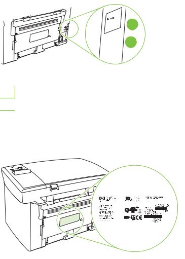
Serial number and model number location
The serial number and product model number label is on the rear of the product.
|
6 Chapter 1 Product information |
ENWW |

Software description
Supported operating systems
The product supports the following operating systems:
|
Full software installation |
Print and scan drivers only |
|||
|
● |
Windows XP (32-bit) |
● |
Windows XP (64-bit) |
|
|
● |
Windows Vista (32-bit) |
● |
Windows Vista |
(64-bit) |
|
● |
Windows 2000 |
● Windows 2003 |
Server (64-bit) |
●Windows 2003 Server (32-bit)
●Mac OS X v10.3, v10.4, and later
 NOTE: For Mac OS X v10.4 and later, PPC and Intel Core Processor Macs are supported.
Supported printer drivers
The product comes with software for Windows and Macintosh that allows the computer to communicate with the product. This software is called a printer driver. Printer drivers provide access to product features, such as printing on custom-sized paper, resizing documents, and inserting watermarks.
 NOTE: The most recent drivers are available at www.hp.com/support/LJM1120. Depending on the configuration of Windows-based computers, the installation program for the product software automatically checks the computer for Internet access in order to obtain the latest drivers.
Software included with the product
There are several options for completing a recommended install. Easy installation will complete the installation with default settings. Advanced installation allows you to review the license agreements and the default settings.
Easy installation for Windows
●HP drivers
◦Printer driver
◦Scan driver
●HP MFP software
◦HP LaserJet Scan program
◦Uninstall program
●HP Update program
●HP Customer Participation program
|
ENWW |
Software description 7 |
●Shop for HP Supplies program
●Other programs
◦ Readiris OCR (not installed with other software; separate installation is required)
Advanced installation
Advanced installation includes all of the features that are available with the easy installation. The HP Customer Participation program is optional.
Macintosh software
●HP Product Setup Assistant
●HP Uninstaller
●HP LaserJet software
◦HP Scan
◦HP Director
◦Scan to e-mail program
◦HP Photosmart
|
8 Chapter 1 Product information |
ENWW |
Software for Windows
Embedded Web server (network models only)
Network models are equipped with an embedded Web server, which provides access to information about device and network activities. This information appears in a Web browser, such as Microsoft Internet Explorer, Netscape Navigator, Apple Safari, or Firefox.
The embedded Web server resides on the device. It is not loaded on a network server.
The embedded Web server provides an interface to the device that anyone who has a networkconnected computer and a standard Web browser can use. No special software is installed or configured, but you must have a supported Web browser on your computer. To gain access to the embedded Web server, type the IP address for the device in the address line of the browser. (To find the IP address, print a configuration page.)
Status Alerts software
The Status Alerts software provides information about the current status of the product.
The software also provides pop-up alerts when certain events occur, such as an empty tray or a problem with the product. The alert includes information about solving the problem.
Other Windows components and utilities
●Software installer — automates the printing system installation
●Online Web registration
|
ENWW |
Software for Windows 9 |
Software for Macintosh
Embedded Web server (network models only)
Network models are equipped with an embedded Web server, which provides access to information about device and network activities. This information appears in a Web browser, such as Microsoft Internet Explorer, Netscape Navigator, Apple Safari, or Firefox.
The embedded Web server resides on the device. It is not loaded on a network server.
The embedded Web server provides an interface to the device that anyone who has a networkconnected computer and a standard Web browser can use. No special software is installed or configured, but you must have a supported Web browser on your computer. To gain access to the embedded Web server, type the IP address for the device in the address line of the browser. (To find the IP address, print a configuration page.)
HP Director
HP Director is a software program for working with documents. HP Director appears on the computer screen to initiate scanning, or to change settings on the product through Macintosh Configure Device.
Also included is the HP product Setup Assistant, which sets up the print queue.
|
10 Chapter 1 Product information |
ENWW |
Uninstall software
Windows
1.Click Start, and then click All Programs.
2.Click HP, and then click HP LaserJet M1120.
3.Click Uninstall, and then follow the onscreen instructions to remove the software.
Macintosh
To remove the software, drag the PPD files to the trash can.
|
ENWW |
Uninstall software 11 |

Media specifications
Supported paper and print media sizes
This product supports a number of paper sizes, and it adapts to various media.
 NOTE: To obtain best print results, select the appropriate paper size and type in the print driver before printing.
Table 1-2 Supported paper and print media sizes
|
Size |
Dimensions |
Priority input tray |
Tray 1 |
|
Letter |
216 x 279 mm (8.5 x 11 in) |
||
|
Legal |
216 x 356 mm (8.5 x 14 in) |
||
|
A4 |
210 x 297 mm (8.27 x 11.69 in) |
||
|
Executive |
184 x 267 mm (7.24 x 10.51 in) |
||
|
A3 |
297 x 420 mm (11.69 x 16.54 in) |
||
|
A5 |
148 x 210 mm (5.83 x 8.27 in) |
||
|
A6 |
105 x 148 mm (4.13 x 5.83 in) |
||
|
B5 (JIS) |
182 x 257 mm (7.17 x 10.12 in) |
||
|
16k |
197 x 273 mm (7.75 x 10.75 in) |
||
|
16k |
195 x 270 mm (7.7 x 10.6 in) |
||
|
16k |
184 x 260 mm (7.25 x 10.25 in) |
||
|
8.5 x 13 |
216 x 330 mm (8.5 x 13 in) |
||
|
4 x 61 |
107 x 152 mm (4 x 6 in) |
||
|
5 x 81 |
127 x 203 mm (5 x 8 in) |
||
|
10 x 15 cm1 |
100 x 150 mm (3.9 x 5.9 in) |
||
|
Custom |
Priority input tray: Minimum—76 x 127 mm (3 x |
||
|
5 in); Maximum—216 x 356 mm (8.5 x 14 in) |
1 These sizes are supported as custom sizes.
Table 1-3 Supported envelopes and postcards
|
Size |
Dimensions |
Priority input tray |
Tray 1 |
|
Envelope #10 |
105 x 241 mm (4.13 x 9.49 in) |
||
|
Envelope DL |
110 x 220 mm (4.33 x 8.66 in) |
||
|
12 Chapter 1 Product information |
ENWW |

Table 1-3 Supported envelopes and postcards (continued)
|
Size |
Dimensions |
Priority input tray |
Tray 1 |
|
Envelope C5 |
162 x 229 mm (6.93 x 9.84 in) |
||
|
Envelope B5 |
176 x 250 mm (6.7 x 9.8 in) |
||
|
Envelope Monarch |
98 x 191 mm (3.9 x 7.5 in) |
||
|
Postcard |
100 x 148 mm (3.94 x 5.83 in) |
||
|
Double postcard |
148 x 200 mm (5.83 x 7.87 in) |
||
Supported paper types and tray capacity
This product has the following tray priority for feeding print media:
1.Priority input tray
2.Tray 1
Minimum media dimensions are 76 x 127 mm (3 x 5 in).
Maximum media dimensions are 216 x 356 mm (8.5 x 14 in).
To obtain the best print results, change the paper size and paper type settings in the printer driver before printing.
Table 1-4 Supported paper types and tray capacity
|
Type is |
Media specifications |
Priority input tray |
Tray 1 capacity1 |
|
Plain |
75 g/m2 (20 lb) to 104 g/m2 (27 lb) |
Up to 10 sheets |
Up to 250 sheets |
|
Color |
|||
|
Preprinted |
|||
|
Prepunched |
|||
|
Recycled |
|||
|
Light |
60 g/m2 (16 lb) to 75 g/m2 (20 lb) |
Up to 10 sheets |
Up to 260 sheets |
|
Envelopes |
Less than 90 g/m2 (24 lb) |
1 envelope |
Up to 10 envelopes. |
|
Labels |
Standard |
1 sheet |
Not supported. |
|
Bond |
75 g/m2 (20 lb) to 104 g/m2 (27 lb) |
1 sheet |
Up to 250 sheets |
|
Rough |
75 g/m2 (20 lb) to 104 g/m2 (27 lb) |
1 sheet |
Up to 200 sheets |
|
Transparencies |
4 mm (0.1 in) Monochrome |
1 sheet |
Up to 200 sheets. |
|
Overhead |
|||
|
Heavy |
110 g/m2 (29 lb) to 125 g/m2 |
Up to 10 sheets |
Not supported. |
|
(33 lb) |
|||
|
Letterhead |
75 g/m2 (20 lb) to 104 g/m2 (27 lb) |
Up to 10 sheets |
Up to 250 sheets |
1 The maximum stack height for tray 1 is 25 mm (1 inch).
|
ENWW |
Media specifications 13 |
|
14 Chapter 1 Product information |
ENWW |
![]()
2 Installation
●Site preparations
●What was in the box
●Install input devices
●Install supplies

Site preparations
Operating environment
Place the product on a sturdy, level surface in a well-ventilated area. Make sure that the air vents are not blocked and that the product is installed away from direct sunlight, open flames, and ammonia fumes.
Store or install the product in an area that meets the following requirements:
●Temperature (printer; operating) 15o to 32.5o C (59o to 90.5o F)
●Temperature (printer; storage) -20o to 60oC (-4o to 140oF)
●Humidity (printer; operating) 10% to 80% relative humidity (no condensation)
●Humidity (printer; storage) 10% to 90% relative humidity (no condensation)
●Temperature (toner cartridge; storage) -20o to 40o C (-4o to 104o F)
●Humidity (toner cartridge; storage) 10% to 90% relative humidity (no condensation)
|
16 Chapter 2 Installation |
ENWW |
Minimum system requirements
●Windows® 2000
●Windows XP
●Windows Server 2003
●Windows Vista
●Mac OS X v10.3 and later
●128 MB RAM for Windows operating systems
●32 MB RAM for Macintosh operating systems
●250 MB hard-disk space (full installation)
●CD-ROM drive
●USB port
|
ENWW |
Site preparations 17 |

What was in the box
The following components are included in the box.
 NOTE: The USB and network cables are not included.
|
5 |
||
|
2 |
3 |
|
|
7 |
||
|
6 |
||
|
1 |
4 |
|
|
8 |
||
Item Description
1HP LaserJet M1120 MFP
2Print cartridge
3Control-panel faceplate (if not already installed)
4Output bin extension
5Start guide and support flyer
6CD-ROMs (software and online user guide)
7Power cord
8Tray 1
|
18 Chapter 2 Installation |
ENWW |

Install input devices
Priority input tray
The priority input tray is accessed from the front of the product. The product prints from the priority input tray before attempting to print from tray 1.
Media guides ensure that the media is correctly fed into the product and that the print is not skewed (crooked on the media). When loading media, adjust the media guides to match the width of the media that you are using.
|
ENWW |
Install input devices 19 |

Tray 1
1.Push tray 1 into the product.
2.Open the tray cover, and then adjust the media guides out.
3.Load the paper in the tray, snug the media guides against the stack, and then close the tray cover.
|
20 Chapter 2 Installation |
ENWW |

Install supplies
Install the print cartridge
1.Open the print-cartridge door.
2.Remove the new print cartridge from its packaging, and then rock the print cartridge back and forth.
3.Remove the orange cover from the print cartridge, and then pull the orange tab straight out to remove the sealing tape.

4.Insert the cartridge into the product until it is firmly in place.
5.Close the print-cartridge door.
|
22 Chapter 2 Installation |
ENWW |

3 Maintenance
●Manage supplies
●Clean the product
●Management tools

Manage supplies
Inspect any parts that wear when servicing the product. Replace them as needed, based on failure or wear rather than usage.
The following table lists approximate schedules for replacing consumables.
Life expectancies of supplies
|
Item |
Capacity |
|
HP LaserJet M1120 MFP Series |
Recommended maximum of 3,000 pages per month |
|
Print cartridge |
2,000 pages1 (standard) |
1 For information about the yield for the cartridges, see www.hp.com/go/pageyield. Actual yield depends on specific use.
Check and order supplies
Hewlett-Packard recommends that you place an order for a replacement print cartridge when the Low message for a print cartridge first appears. Use a new, authentic HP print cartridge to obtain the following types of supplies information:
●Amount of cartridge life remaining
●Estimated number of pages remaining
●Number of pages printed
●Other supplies information
Store supplies
Follow these guidelines for storing print cartridges:
●Do not remove the print cartridge from its package until you are ready to use it.
 CAUTION: To prevent damage, do not expose the print cartridge to light for more than a few minutes.
●See Environmental specifications on page 187 for operating and storage temperature ranges.
●Store the supply in a horizontal position.
●Store the supply in a dark, dry location away from heat and magnetic sources.
|
24 Chapter 3 Maintenance |
ENWW |
![]()
Replace supplies
Print cartridge
1.Open the print-cartridge door.
2.Grasp the handle on the print cartridge, and then pull the cartridge straight out to remove it. See the recycling information inside the print cartridge box.
3.Remove the new print cartridge from its packaging, and then rock the print cartridge back and forth.

4.Remove the orange cover from the print cartridge, and then pull the orange tab straight out to remove the sealing tape.
5.Insert the cartridge into the product until it is firmly in place.
6.Close the print-cartridge door.
 CAUTION: If toner gets on any clothing, wipe it off with a dry cloth and wash the clothing in cold water.
Hot water sets toner into the fabric.
HP policy on non-HP supplies
Hewlett-Packard Company cannot recommend the use of non-HP supplies, either new or remanufactured. Because they are not HP products, HP cannot influence their design or control their quality. Service or repairs required as a result of using a non-HP supply will not be covered under the warranty.
|
26 Chapter 3 Maintenance |
ENWW |
HP fraud hotline
Call the HP fraud hotline if the product indicates that the print cartridge is not an HP print cartridge and you think that it is genuine. HP will help determine if the product is genuine and take steps to resolve the problem.
The print cartridge might not be a genuine HP one if you notice the following issues:
●You are experiencing a large number of problems with the print cartridge.
●The print cartridge does not look like it usually does (for example, the pull tab or the box is different).
In the United States, call toll-free: 1-877-219-3183.
Outside the United States, you can call collect. Dial the operator and ask to place a collect call to this telephone number: 1-770-263-4745. If you do not speak English, a representative at the HP fraud hotline who speaks your language will assist you. Or, if someone who speaks your language is not available, a language line interpreter will connect approximately one minute after the beginning of the call. The language line interpreter is a service that will translate between you and the representative for the HP fraud hotline.

Clean the product
Clean the exterior
Use a soft, damp, lint-free cloth to wipe dust, smudges, and stains off of the exterior of the product.
Clean the flatbed scanner glass
Dirty glass, from fingerprints, smudges, hair, and so on, slows down performance and affects the accuracy of special features such as fit-to-page and copy.
1.Turn off the product, unplug the power cord from the electrical outlet, and raise the scanner cover.
2.Clean the glass by using a soft cloth or sponge that has been moistened with nonabrasive glass cleaner.
 CAUTION: Do not use abrasives, acetone, benzene, ammonia, ethyl alcohol, or carbon tetrachloride on any part of the product; these can damage the product. Do not place liquids directly on the glass. They might seep under it and damage the product.
Clean the lid backing
Minor debris can accumulate on the white document lid backing that is located underneath the product lid.
1.Turn off the product, unplug the power cord, and raise the lid.
2.Clean the white document lid backing by using a soft cloth or sponge that has been moistened with a mild soap and warm water. Wash the backing gently to loosen debris; do not scrub the backing.
|
28 Chapter 3 Maintenance |
ENWW |

3.Dry the backing by using a chamois or soft cloth.
 CAUTION: Do not use paper-based wipes because they might scratch the backing.
4.If this does not clean the backing well enough, repeat the previous steps and use isopropyl alcohol to dampen the cloth or sponge, and then wipe the backing thoroughly with a damp cloth to remove any residual alcohol.
Clean the paper path
During the printing process, paper, toner, and dust particles can accumulate inside the product. Over time, this buildup can cause print-quality problems such as toner specks or smearing. This product has a cleaning mode that can correct and prevent these types of problems.
|
Specks |
Smearing |
||
1.Press Setup.
2.Use the arrow buttons to find the Service menu, and then press OK.
3.Use the arrow buttons to find Cleaning mode, and then press OK.
4.Load plain letter or A4 paper when you are prompted.
5.Press OK again to confirm and begin the cleaning process.
A page feeds through the product slowly. Discard the page when the process is completed.
|
ENWW |
Clean the product 29 |

Management tools
Information pages
Information pages reside within the product memory. These pages help diagnose and solve problems with the product.
 NOTE: If the product language was not correctly set during installation, you can set the language manually so the information pages print in one of the supported languages. Change the language by using the System setup menu on the control panel or the embedded Web server (network models only).
|
Page description |
How to print the page |
|
|
Demo page |
1. |
On the product control panel, press Setup. |
|
Contains examples of text and graphics. |
2. |
Use the arrow buttons to select Reports, and then press |
|
OK. |
||
|
3. |
Use the arrow buttons to select Demo page, and then |
|
|
press OK. |
||
|
Menu map |
1. |
On the product control panel, press Setup. |
|
Shows the control-panel menus and available settings. |
2. |
Use the arrow buttons to select Reports, and then press |
|
OK. |
||
|
3. |
Use the arrow buttons to select Menu structure, and then |
|
|
press OK. |
||
|
Configuration page |
1. |
On the product control panel, press Setup. |
|
Shows the current settings and product properties. |
2. |
Use the arrow buttons to select Reports, and then press |
|
OK. |
||
|
3. |
Use the arrow buttons to select Config report, and then |
|
|
press OK. |
||
Embedded Web server
This product is equipped with an embedded Web server (EWS), which provides access to information about product and network activities. A Web server provides an environment in which web programs may run, much in the same way that an operating system, such as Windows, provides an environment for programs to run on a computer. The output from these programs can then be displayed by a Web browser, such as Microsoft Internet Explorer, Safari, or Netscape Navigator.
An “embedded” Web server resides on a hardware device (such as an HP LaserJet product) or in firmware, rather than as software that is loaded on a network server.
The advantage of an EWS is that it provides an interface to the product that anyone with a networkconnected product and computer can use. There is no special software to install or configure, but you must have a supported Web browser on the computer. To gain access to the EWS, type the IP address for the product in the address line of the browser. (To find the IP address, print a configuration page.)
 NOTE: For Macintosh operating systems, you can use the EWS over a USB connection after installing the Macintosh software included with the product.
|
30 Chapter 3 Maintenance |
ENWW |

Features
The EWS allows you to view product and network status and manage printing functions from a computer. With the EWS, you can complete the following tasks:
●View product status information
●Determine the remaining life on all supplies and order new ones
●View and change part of the product configuration
●View and print some internal pages
●Select the language in which to display the EWS pages
●View and change network configuration
●Set, change, or clear the product security password
 NOTE: Changing network settings in the EWS might disable some of product software or features.
|
32 Chapter 3 Maintenance |
ENWW |

4 Operational theory
●Basic operation
●Scanner functions and operation
●Internal components (base unit)
●Engine control system
●Laser/scanner system
●Pickup/feed/delivery system
●Image-formation system

Basic operation
This chapter presents an overview of the relationships between major components in the product, and includes a detailed discussion of the image-formation system. The following systems are discussed:
●Engine control system
●Laser/scanner system
●Pickup/feed/delivery system
●Image-formation system
Figure 4-1 System block diagram
Sequence of operation for the base unit
Operational sequences are controlled by the microprocessor on the DC controller.
Table 4-1 Sequence of operation
|
WAIT |
From power-on until the end of the main-motor initial |
|
drive |
Detects the presence of a print cartridge; clears potential from the drum surface and cleans the transfer roller
|
STBY (standby) |
From the end of the WAIT or LSTR period until either |
Prepares the product to receive print commands |
|
a print command is sent from the formatter or the |
||
|
power is turned off |
||
|
INTR (initial |
From the time of the print command until the pickup |
Prepares the photosensitive drum for printing |
|
rotation) |
solenoid is turned on |
|
|
34 Chapter 4 Operational theory |
ENWW |
 Loading…
 Главная
Автомагнитолы
DVD
Материнские платы
Мобильные телефоны
Мониторы
Ноутбуки
Принтеры
Планшеты
Телевизоры
Даташиты
Маркировка SMD
Форум
МФУ HP LaserJet M1120 MFP — Сервис-мануалы и схемы, разборка / сборка. Скачать бесплатно.
МФУ HP LaserJet M1120 MFP — Сервис-мануалы и схемы, разборка / сборка. Скачать бесплатно.

МФУ
HP LaserJet M1120 MFP
— Руководство по обслуживанию. Скачать
File Specifications:413/413288-laserjet_m1120__multifunction_printer.pdf file (14 Jun 2023) |
Accompanying Data:
HP LaserJet M1120 MFP Series All in One Printer PDF Service Manual (Updated: Wednesday 14th of June 2023 10:46:38 PM)
Rating: 4.7 (rated by 36 users)
Compatible devices: Color LaserJet Pro M252, Photosmart C6300 — All-in-One Printer, LaserJet M4349 — Multifunction Printer, 4730mfp, 410, Officejet 4315, LaserJet Enterprise MFP M725, M3027.
Recommended Documentation:
Service Manual (Text Version):
(Ocr-Read Summary of Contents of some pages of the HP LaserJet M1120 MFP Series Document (Main Content), UPD: 14 June 2023)
-
130, 6. Replace the print cartridge and close the print-cartridge door. 114 Chapter 6 Problem solve ENWW
… -
79, 7. Grasp the tab on the gear-drive arm bracket and carefully flex it away from the scanner assembly to release the bracket. Figure 5-19 Remove the scanner assembly (7 of 10) 8. Push the bracket toward the right side of the product until its mounting tabs clear the holes in the scanner assembly. Figure 5-20 Remove the scanner assembly (8 of 10) ENWW Scanner assembly 63
… -
188, Internal components (2 of 3) Figure 7-5 Internal components (2 of 3) 2 3 4 1 5 6 172 Chapter 7 Parts ENWW
… -
113, 3. Disconnect two wire-harness connectors (callout 3; J102, and J552) and remove the harnesses from the retainer (callout 4). NOTE: You might need to disconnect and remove the other wire harnesses to remove the required harness from the retainer. Figure 5-75 Remove the fuser (2 of 6) 4 3 4. Release the wire harness from the retainer near the top of the fuser (callout 5) and disconnect the ground wire (callout 6) from the back of the product. Figure 5-76 Remove the fuser (3 of …
-
157, Interface ports All models have a Hi-Speed USB 2.0 port. The HP LaserJet M1120n also has a 10/100 Base-T (RJ-45) network port. 1 2 1 Hi-Speed USB 2.0 port 2 Network port (HP LaserJet M1120n only) ENWW Problem-solving diagrams 141
… -
80, 9. Use a small flat-blade screwdriver to release the tabs on each link assembly. WARNING! When the links are disengaged, the scanner assembly can easily fall off of the product base if it is rotated too far toward the back of the product. CAUTION: Do not push too hard on the link tabs or the tabs might break. Figure 5-21 Remove the scanner assembly (9 of 10) 10. Rotate the scanner assembly toward the rear of the product until the rear hinges …
-
95, Front cover 1. Remove the right-side and left-side covers. See Side covers on page 74. 2. Release the lower left-side front-cover locking tab and slightly pry the lower-left corner of the front cover away from the product. Figure 5-46 Remove the front cover (1 of 4) 3. Release the lower right-side front-cover locking tab (located near the corner of the power supply) and slightly pry the lower-right corner of the front cover away from the product. Figure 5-47 Remove the front cover (2 …
-
206, FCC compliance This equipment has been tested and found to comply with the limits for a Class B digital device, pursuant to Part 15 of the FCC rules. These limits are designed to provide reasonable protection against harmful interference in a residential installation. This equipment generates, uses, and can radiate radio frequency energy. If it is not installed and used in accordance with the instructions, it may cause harmful interference to r…
-
77, 3. Release the bottom tab (callout 2). Figure 5-15 Remove the scanner assembly (3 of 10) 2 4. Rotate the back side of the cover away from the product, and then slide the cover toward the front of the product to remove it. Figure 5-16 Remove the scanner assembly (4 of 10) 2 1 ENWW Scanner assembly 61
… -
100, HP LaserJet M1120 MFP Series 6. Release the wire harness from the retainer (callout
 on the power supply. Figure 5-55 Remove the power supply (5 of 7) 8 7. Unclip two clips (callout 9) and remove one plastic bracket (callout 10). CAUTION: The wire harness (callout 11) attached to the bracket is not captive. Do not lose this wire harness when the bracket is removed. Figure 5-56 Remove the power supply (7 of 7) 9 11 10 84 Chapter 5 Removal and replacement ENWW
… -
139, Problem Example Cause Solution The printed page contains wrinkles or creases. The media might be loaded incorrectly or the input tray might be too full. Turn over the stack of paper in the input tray, or try rotating the paper 180° in the input tray. Verify that the media is loaded correctly and that the media guides are not too tight or too loose against the stack. See Install input devices on page 19. The media might not me…
-
123, Step number Verification step Possible problems Solutions 6 Does the product scan to the computer? Initiate a scan from the basic desktop software at your computer. The cable is not connected correctly. Reconnect the cable. Software is not installed correctly or an error occurred during software installation. Uninstall and then reinstall the product software. Verify that you are using the correct installation procedure …
-
133, Avoid repeated jams ● Verify that the input tray is not overfilled. The input tray capacity varies depending on the type of print media that you are using. ● Verify that the media guides are properly adjusted. ● Check that the input tray is securely in place. ● Do not add print media into the input tray while the product is printing. ● Use only HP-recommended media types and sizes. ● Do not fan media prior to loading it in a tray. To l…
-
88, 3. Depress the pickup-tray locking tabs to release the media input tray, and then pull it out and away from the product. Figure 5-35 Remove the media input tray (3 of 3) 72 Chapter 5 Removal and replacement ENWW
… -
111, 5. Remove two screws (callout 6). Carefully slip the main-motor drive belt off of the motor shaft (callout 7), and then remove the main motor. Figure 5-73 Remove the main motor (4 of 4) 6 7 TIP: When the main motor is reinstalled, make sure that the wire harness is located toward the top of the motor so that the harness can be correctly positioned in the retainers on the motor PCA mounting bracket. When you reinstall the main-motor drive belt, make sure that it is correctly pos…
 on the power supply. Figure 5-55 Remove the power supply (5 of 7) 8 7. Unclip two clips (callout 9) and remove one plastic bracket (callout 10). CAUTION: The wire harness (callout 11) attached to the bracket is not captive. Do not lose this wire harness when the bracket is removed. Figure 5-56 Remove the power supply (7 of 7) 9 11 10 84 Chapter 5 Removal and replacement ENWW
-
HP LaserJet M1120 MFP Series User Manual
-
HP LaserJet M1120 MFP Series User Guide
-
HP LaserJet M1120 MFP Series PDF Manual
-
HP LaserJet M1120 MFP Series Owner’s Manuals
Recommended: VCWB300, EAS23, MMP8001 Series, MultiConnect mDotT
Links & Tools
Operating Impressions, Questions and Answers:
- About
- Blog
- Projects
- Help
-
Donate
Donate icon
An illustration of a heart shape - Contact
- Jobs
- Volunteer
- People
Bookreader Item Preview
texts
HP LaserJet M1120 MFP Series — Service Manual. www.s
- Addeddate
- 2021-04-01 20:27:02
- Identifier
- manualzilla-id-6030156
- Identifier-ark
- ark:/13960/t3qw47s8p
- Ocr
- tesseract 5.0.0-alpha-20201231-10-g1236
- Ocr_autonomous
- true
- Ocr_detected_lang
- en
- Ocr_detected_lang_conf
- 1.0000
- Ocr_detected_script
- Latin
- Ocr_detected_script_conf
- 0.9994
- Ocr_module_version
- 0.0.13
- Ocr_parameters
- -l fra+eng+lat+Latin
- Page_number_confidence
- 92.31
comment
Reviews
There are no reviews yet. Be the first one to
write a review.
32
Views
DOWNLOAD OPTIONS
Uploaded by
chris85
on
SIMILAR ITEMS (based on metadata)
Table of Contents for HP LaserJet M1120 MFP Series:
-
List of tables Table 1-1 Product guides ………………………………………………………………………………………………………………….. 2 Table 1-2 Supported paper and print media sizes ………………………………………………………………………………. 12 Table 1-3 Supported envelopes and postcards …………………………………….
-
HP LaserJet M1120 MFP Service Manual HP LaserJet M1120 MFP Service Manual HP LaserJet M1120 MFP Service Manual HP LaserJet M1120 MFP Service Manual HP LaserJet M1120 MFP Service Manual HP LaserJet M1120 MFP Service Manual HP LaserJet M1120 MFP Service Manual HP LaserJet M1120 MFP Service Manual HP LaserJet M1120 MFP Service Manual
-
input tray loading media 19 install tray 1 20 installation, software advanced 8 easy 7 installing Windows software 7 installing hardware scanner cushions 70 interface ports cables, ordering 152 locating 6, 141 types included 4 internal components 38 internal components, part numbers 170 J jams causes of 111 locating 112 output-bin, clearing 115 preventing 117 print cartridge area, clearing 116 trays, clearing 112 K Korean EMI statement 195 L laser safe
-
HP LaserJet M1120 MFP Series Service Manual
-
Index Symbols/Numerics 600 dpi print-quality setting 118 A accessibility features 4 accessories part numbers 152 acoustic emissions 187 advanced software installation 8 after service checklist 50 alert messages 108 archive print setting 138 assemblies high-voltage connector, cleaning 134 part numbers 166 B background shading, troubleshooting 121 bands and streaks, troubleshooting 120 batteries included 192 before service checklist 49 bin, output capacity 4 jams, clearing 115 locating 5 blank copies, troubleshooting 130 blank scan
-
External covers and panels ……………………………………………………………………………………………….. 168 Internal components (1 of 3) ……………………………………………………………………………………………… 170 Internal components (2 of 3) ……………………………………………………………………………………………… 172 Internal components (3 of 3) …………………………………..
-
Table of contents 1 Product information Quick access to product information ………………………………………………………………………………………. 2 Product comparison …………………………………………………………………………………………………………….. 3 Product features ………………………………………………………………………………………………………………….. 4 Product walkaround ……………………………………….
-
media detection 42 scanner operations 36 separation pad replacing 66 separation pad, locating 38 separation pads diagrams 147 sequence of operations 34 serial number, locating 6 service critical error messages 109 part numbers 152 repacking device 184 secondary menu 135 service agreements 184 Service menu 138 servicing 49 servicing product 48 settings configuration page 137 factory-set defaults, restoring 138 NVRAM initialization 135 shipping device 184 side covers
-
6 Problem solve ● Problem-solving checklist ● Control-panel messages ● Clear jams ● Print problems ● Scan problems ● Copy problems ● Functional checks ● Service-mode functions ● Problem-solving tools ● Problem-solving diagrams ● Firmware updates ENWW 105
-
Image problems ………………………………………………………………………………………………… 127 Media-handling problems …………………………………………………………………………………… 128 Performance problems ………………………………………………………………………………………. 130 Functional checks …………………………………………………………………..
-
7Parts ● Ordering information ● Supplies and hinge tool ● Cable and interface accessories ● Whole-unit replacement ● Control-panel overlays ● Supplementry documentation and support ● Parts lists and diagrams ● Scanner assemblies ● Assemblies ● External covers and panels ● Internal components (1 of 3) ● Internal components (2 of 3) ● Internal components (3 of 3) ● Alphabetical parts list ● Numerical
Questions, Opinions and Exploitation Impressions:
You can ask a question, express your opinion or share our experience of HP LaserJet M1120 MFP Series device using right now.