-
Bookmarks
Quick Links
Operating Instructions
for inclined wheelchair lifts
HIRO 320, HIRO 350, HIRO 360, HIRO 370
Straight and turning platform lift systems
Edition 2.08 1030010
Summary of Contents for HIRO LIFT HIRO 320
-
Page 1
Operating Instructions for inclined wheelchair lifts HIRO 320, HIRO 350, HIRO 360, HIRO 370 Straight and turning platform lift systems Edition 2.08 1030010… -
Page 2
General safety instructions ………………….. Page 6 Summary of HIRO inclined lifts HIRO 320 — turning platform lift system…………….Page 9 HIRO 350 — straight platform lift system…………….Page 10 HIRO 360 — turning lowerable platform lift system…………Page 11 HIRO 370 —… -
Page 3
1. Contents Disposal ………………………. Page 74 Technical data …………………….. Page 75 EC Conformity Declaration…………………. Page 76 Please keep these instructions for further reference! -
Page 4
2. Meaning of symbols and glossary of terms Key to symbols Caution! Risk of personal injury! Attention! Risk of material damage! Advice Multi-floor systems Glossary (list of technical terms) Platform control: Control unit in lift with key switch and command buttons. Remote control: Battery-operated radio transmitter unit with control buttons and indicator light. -
Page 5
• the system is kept in a safe operational state. • the regular maintenance works are carried out by HIRO LIFT or by a representative authorised by HIRO LIFT. • repairs are carried out by HIRO LIFT or by a representative authorised by HIRO LIFT. -
Page 6
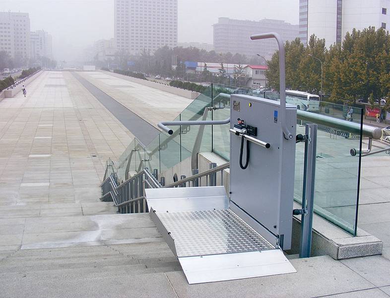
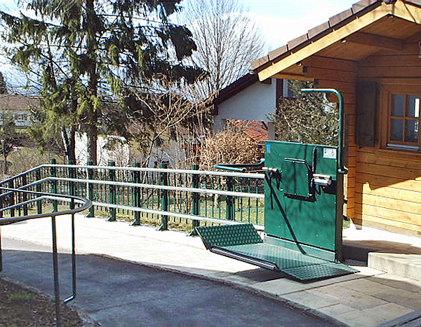
• In model HIRO 350Z, the toothed drive rack must be regularly lubricated with grease. Contact the HIRO LIFT service department. • An outdoor inclined platform lift is subject to a risk of slipping during rain. -
Page 7
• Ensure that there are no obstructions to the movement of the safety barriers. • Inclined wheelchair lifts HIRO 320, HIRO 350 and HIRO 370: The wheelchair brakes must be applied when the wheelchair is on the platform. -
Page 8
4. General safety instructions After using the lift… • After using the lift the keys must be removed and stored safely. Care must be taken to ensure that unauthorised persons, such as children, cannot gain access to the keys. • To keep the stairs clear, always fold away the platform after use. The wheelchair lift should always be parked at a charging station where it least obstructs the stairs. -
Page 9
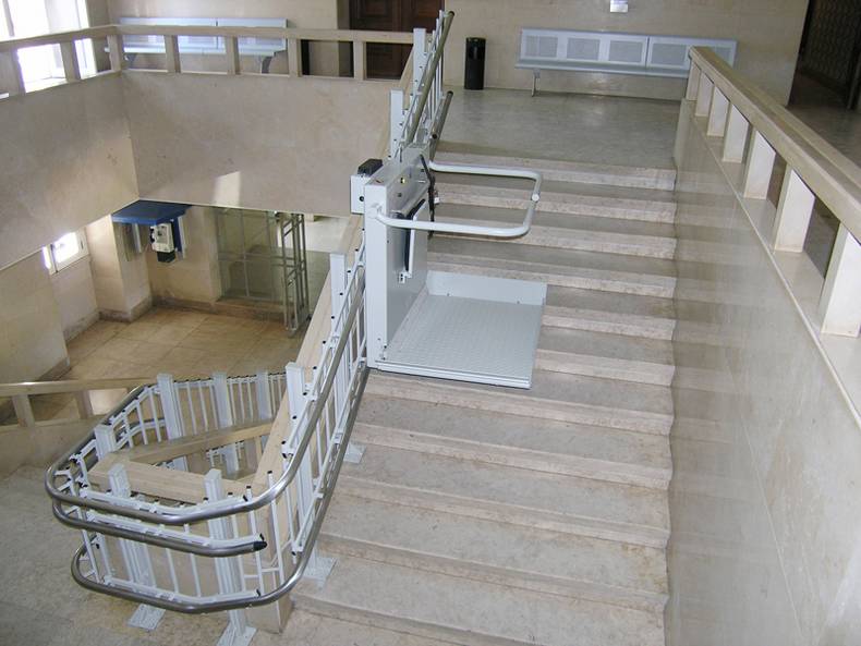
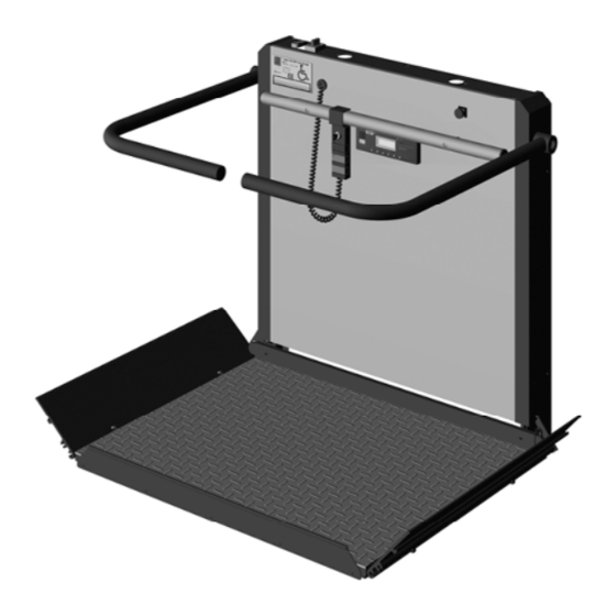
5. Summary of HIRO inclined lifts HIRO 320 — turning platform lift system Top access Magnets Bottom access Actuating cam for emergency limit switch Platform Guard cam Remote control Current collector cam/charging bar Top charging station Rails Fig. 5.1: Platform lift system — Model 320… -
Page 10
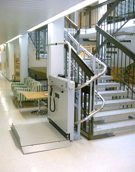
5. Summary of HIRO inclined lifts HIRO 350 — straight platform lift system Top access Magnets Bottom access Contact cam for emergency limit switch Platform Current collector cam/charging bar Remote control Top charging station Bottom charging station Guide rails Fig. 5.2: Platform lift system — Model 350… -
Page 11
5. Summary of HIRO inclined lifts HIRO 360 — turning, lowerable platform lift system Top access Magnets Bottom access Contact cam for emergency limit switch Platform Guard cam Remote control Current collector cam/charging bar Top charging station Bottom charging station Rails Fig. -
Page 12
5. Summary of HIRO inclined lifts HIRO 370 — turning, lowerable platform lift system Top access Magnets Bottom access Contact cam for emergency limit switch Platform Guard cam Remote control Current collector cam/charging bar Top charging station Bottom charging station Rails Fig. -
Page 13
5. Summary of HIRO inclined lifts Platform components and accessories Platform with contact tray Emergency button (optional) Access ramps with safety contact Key switch for lifts with Safety barriers ON/OFF key switch. Main switch and fuses Lateral collision guard Type plate Platform control Display Emergency stop button… -
Page 14
5. Summary of HIRO inclined lifts Remote control (key-operated) mounting (key operated) Remote control (model without key switch) Key switch for stationary Control light (LED) remote control Key switch remote control Charging device Wall mounting for remote control Accessories for emergency evacuation: Operation key Hand wheel (for some types of lift) ON/OFF key (for certain lifts) -
Page 15
5. Summary of HIRO inclined lifts Safety devices HIRO platform lifts are equipped with a whole range of safety features to ensure safe use of the systems: Emergency stop button In case of emergency you may push the emergency stop button any time. As soon as this button is pushed, all movements of the system are stopped. -
Page 16
5. Summary of HIRO inclined lifts Control priorities The platform control for the lift overrides the remote control. If the wheelchair lift is being operated via the platform controls, operation via remote control is not possible. Compact design When the platform is folded away, its compact construction offers almost unrestricted use of the available space. -
Page 17
6. Operation of HIRO inclined lifts Requirements for initial operation Caution! Before use or initial operation all users must be familiar with the operation of the system. They have to be specially aware of the dangers which can occur through incorrect use of the system! •… -
Page 18
6. Operation of HIRO inclined lifts As an example, the following pages show the operation of a HIRO 320 inclined wheelchair lift with a turning platform lift system. Attention will be drawn to differences to other models. Depending on the site and due to technical changes your system may be different to the pictures. -
Page 19
6. Operation of HIRO inclined lifts 6.2 Key-operated systems There are two different types of key-operated system available: 1. 1. Wheelchair lift with key-operated platform control and remote control The platform controls and the remote control units have a key switch that can be turned to the «ON» or «OFF»… -
Page 20
6. Operation of HIRO inclined lifts When the key (A) on the key switch (B) is turned to the «OFF» position: • the wheelchair lift cannot be set in motion using the platform controls, whether you have removed the key or not. •… -
Page 21
6. Operation of HIRO inclined lifts Call and dispatch the lift (lift with key-operated platform controls and remote control) 6.3.1 Call platform — from downstairs You are at the bottom of the stairs and you want to go up. The wheelchair lift is not at the bottom landing, however, but at a charging station in the middle or at the top of the stairs. -
Page 22
6. Operation of HIRO inclined lifts The buttons on the remote control have two pressure points: — If the button is pressed lightly, the LED (C) lights up but the command is not yet carried out. — The LED (C) only starts to flash and the command is only carried out when the button is pressed firmly. -
Page 23
6. Operation of HIRO inclined lifts Special case Multi-floor systems: You are at the bottom landing and you want to call the platform lift by means of the remote control. Caution! If multi-floor systems are operated with the stationary or portable remote control, the travel path must be completely visible at all times. -
Page 24
6. Operation of HIRO inclined lifts 6.3.2 Riding upstairs The platform is folded and standing at the bottom landing. • Insert the key into the stationary remote control (fig. 6.5) or into the portable remote control (fig. 6.6). • Turn the key to the ON position. In the ON position the key cannot be removed. -
Page 25
6. Operation of HIRO inclined lifts Caution! To avoid injuries, always put the wheelchair correctly onto the platform. On the platform the wheelchair has to be secured against rolling (exception: HIRO 360 inclined wheelchair lift). Make sure that the safety barriers and the access ramps can be moved easily. -
Page 26
6. Operation of HIRO inclined lifts • Insert the key into the platform control. • Turn the key to the ON position. • Push the UP button (A) on the platform control. First the safety barrier and the access ramp close. They block the exit as a result. -
Page 27
6. Operation of HIRO inclined lifts You have finished your ride and no longer need the platform. • Turn the key on the platform controls to the OFF position. • Remove the key. It is important that you remember to remove the key, because the wheelchair lift cannot be operated via remote control when the key in the platform control is set to the ON position. -
Page 28
6. Operation of HIRO inclined lifts 6.3.3 Call platform — from upstairs You are at the top of the stairs and you want to go down. The wheelchair lift is not at the top landing, however, but at a charging station in the middle or at the bottom of the stairs. -
Page 29
6. Operation of HIRO inclined lifts Special case Multi-floor systems: You are at the top landing and want to call the platform lift by means of the remote control. Caution! If multi-floor systems are operated with the stationary or portable remote control, the travel path must be completely visible any time. -
Page 30
6. Operation of HIRO inclined lifts 6.3.4 Riding downstairs The platform is folded and standing at the upper landing. • Insert the key into the stationary remote control (fig. 6.17) or into the portable remote control (fig. 6.18). • Turn the key to the ON position. In the ON position the key cannot be removed. -
Page 31
6. Operation of HIRO inclined lifts Caution! To avoid injuries, always put the wheelchair correctly onto the platform. On the platform the wheelchair has to be secured against rolling (exception: HIRO 360 inclined wheelchair lift). Make sure that the safety barriers and the access ramps can be moved easily. -
Page 32
6. Operation of HIRO inclined lifts • Insert the key into the platform control. • Turn the key to the ON position. • Push the DOWN button (A) on the platform control. First the safety barrier and the access ramp close. So they block the exit. -
Page 33
6. Operation of HIRO inclined lifts You have finished your ride and no longer need the platform. • Turn the key on the platform controls to the OFF position. • Remove the key. It is important that you remember to remove the key, because the wheelchair lift cannot be operated via remote control when the key in the platform control is set to the ON position. -
Page 34
6. Operation of HIRO inclined lifts Calling the wheelchair lift and riding (lift with ON/OFF key) 6.4.1 Call platform — from downstairs You are at the bottom of the stairs and you want to go up. The wheelchair lift is not at the bottom landing, however, but at a charging station in the middle or at the top of the stairs. -
Page 35
6. Operation of HIRO inclined lifts Special case Multi-floor systems: You are at the bottom landing and you want to call the platform lift by means of the remote control. Caution! If multi-floor systems are operated with the stationary or portable remote control, the travel path must be completely visible at all times. -
Page 36
6. Operation of HIRO inclined lifts 6.4.2 Riding upstairs The platform is folded and standing at the bottom landing. • Insert the key into the key switch, if it is not already inserted. • Turn the key to the ON position. Fig. -
Page 37
6. Operation of HIRO inclined lifts Caution! To avoid injuries, always put the wheelchair correctly onto the platform. On the platform the wheelchair has to be secured against rolling (exception: HIRO 360 inclined wheelchair lift). Make sure that the safety barriers and the access ramps can be moved easily. -
Page 38
6. Operation of HIRO inclined lifts • Push the UP button (A) on the platform control. First the safety barrier and the access ramp close. They block the exit as a result. Then the platform starts to move. If the lift is overloaded, or the load is very unevenly distributed, when it leaves the bottom landing, then the overload switch will be triggered within… -
Page 39
6. Operation of HIRO inclined lifts When you arrive at the top landing, there are two options: Option 1: Leaving the wheelchair lift ready for use. Option 2: Switching off the platform lift. Option 1: Leaving the wheelchair lift ready for use The platform must now be turned back to the travelling position so that it does not block the stairs. -
Page 40
6. Operation of HIRO inclined lifts Caution! The wheelchair lift can still be set in motion using either the platform controls or the remote controls, since the key switch is still set to the «ON» position. The operator of the system is responsible for the safe and proper use of the lift. Everyone who uses the lift must be instructed in its use and be familiar with the system. -
Page 41
6. Operation of HIRO inclined lifts Option 2: Switching off the platform The platform must now be turned back to the travelling position so that it does not block the stairs. • Push the DOWN button (B) on the stationary or portable remote control and keep it pressed until the platform has folded. -
Page 42
6. Operation of HIRO inclined lifts Caution! When the wheelchair lift is not in use, the key must be kept in a safe place to ensure that unauthorised persons, such as children, cannot use the lift. If the key switch is set to the OFF position, the wheelchair lift cannot be operated, whether the key has been removed or not. -
Page 43
6. Operation of HIRO inclined lifts 6.4.3 Call platform — from upstairs You are at the top of the stairs and you want to go down. The wheelchair lift is not at the top landing, however, but at a charging station in the middle or at the bottom of the stairs. -
Page 44
6. Operation of HIRO inclined lifts Special case Multi-floor systems: You are at the top landing and want to call the platform lift by means of the remote control. Caution! If multi-floor systems are operated with the stationary or portable remote control, the travel path must be completely visible any time. -
Page 45
6. Operation of HIRO inclined lifts 6.4.4 Riding downstairs The platform is folded and standing at the top landing. • Insert the key into the key switch, if it is not already inserted. • Turn the key to the ON position. Fig. -
Page 46
6. Operation of HIRO inclined lifts Caution! To avoid injuries, always put the wheelchair correctly onto the platform. On the platform the wheelchair has to be secured against rolling (exception: HIRO 360 inclined wheelchair lift). Make sure that the safety barriers and the access ramps can be moved easily. -
Page 47
6. Operation of HIRO inclined lifts • Push the DOWN button (A) on the platform control. First the safety barrier and the access ramp close. They block the exit as a result. Then the platform starts to move. • Keep the DOWN button (A) pressed until you have reached the desired position. -
Page 48
6. Operation of HIRO inclined lifts When you arrive at the top landing, there are two options: Option 1: You can leave the wheelchair lift ready for use. Option 2: You can switch off the platform lift. Option 1: Leaving the wheelchair lift ready for use The platform must now be turned back to the travelling position so that it does not block the stairs. -
Page 49
6. Operation of HIRO inclined lifts Caution! The wheelchair lift can still be set in motion using either the platform controls or the remote controls, since the key switch is still set to the «ON» position. The operator of the system is responsible for the safe and proper use of the lift. Everyone who uses the wheelchair lift must be instructed in its use and be familiar with the system. -
Page 50
6. Operation of HIRO inclined lifts Option 2: Switching off the platform The platform must now be folded away so that it does not block the stairs. • Push the UP button (B) of the stationary or portable remote control and keep it pressed until the platform has folded. -
Page 51
6. Operation of HIRO inclined lifts Caution! When the wheelchair lift is not in use, the key must be kept in a safe place to ensure that unauthorised persons, such as children, cannot use the lift. If the key switch is set to the OFF position, the wheelchair lift cannot be operated, whether the key has been removed or not. -
Page 52
6. Operation of HIRO inclined lifts Enter and leave the lift at intermediate stops Platform lift systems, e.g. systems extending over several floors, may have additional landings between the top and bottom end landing. At the top landing and at intermediate landings, overloading or very uneven distribution of the load will be detected as soon as the platform floor is… -
Page 53
6. Operation of HIRO inclined lifts Situation 2: You are at an intermediate landing and want to ride upstairs or downstairs. To enter the platform, you need to call it first by means of the remote control. If you have a lift with ON/OFF control, the lift system must be switched on (key switch in ON position). -
Page 54
6. Operation of HIRO inclined lifts Deactivation of the system If the platform lift is not used for a longer period of time, e.g. when you go on vacation for a few weeks, the system can be deactivated. • Turn the main switch on the platform to the OFF position. Attention! When switching off the main switch, the charging system and its components are still under electric power. -
Page 55
6. Operation of HIRO inclined lifts Display The electronic control unit of the HIRO platform lift system shows the respective operating state on its display. When the F buttons are pressed, the saved information will be displayed. Fig. 6.58: Display of system control Button functions: •… -
Page 56
For the HIRO 350Z model: • The upper surfaces of the rails must be cleaned at regular intervals. Remove any dirt and dust with a cloth or vacuum cleaner. • The toothed drive rack must be regularly greased. Contact the HIRO LIFT service department. -
Page 57
7. Dealing with faults Emergency operation In case of emergency, the wheelchair lift can be moved to the nearest stop using either a hand wheel or an electrically operated emergency control facility, depending on the model of lift. Emergency operation of both models is described below: 7.1.1 Moving the platform: Model with hand wheel In case the platform lift cannot be operated with the platform or remote control, it must be moved to a… -
Page 58
7. Dealing with faults Version 2: • Set the main switch to OFF. • Insert the hand wheel (A) into the respective opening. • Pull the brake release lever (B) to release the motor brake. Keep the brake release lever pulled. If the brake release lever (B) is not pulled, the platform is very difficult to move. -
Page 59
Pay attention to the way the wheelchair lift moves: under no circumstances should you continue travelling if you hear loud creaking noises or the lift moves sluggishly. Contact HIRO LIFT’s service department. If your model of lift has a swivel rail, do not carry out the procedure described below •… -
Page 60
7. Dealing with faults 7.1.3 Manually lowering of HIRO 360 and HIRO 370 platform lift systems In case the platform of these models cannot be lowered with the platform control or remote control, it must be lowered by means of the square key. Caution! The platform may be lowered manually only if the main switch is switched off. -
Page 61
7. Dealing with faults Emergency evacuation In case a person in a wheelchair is on the platform and the platform cannot travel to a landing, an emergency evacuation has to be carried out. Caution! Before an emergency evacuation, the system has to be switched off at the main switch. To avoid injuries, an emergency evacuation must always be carried out up the stairs, i.e. -
Page 62
Since the safety barrier is a safety device, after an emergency evacuation the system may only be put into operation again by HIRO LIFT or by an authorised representative of HIRO LIFT. The platform must now be folded away so that it does not block the stairs. -
Page 63
7. Dealing with faults • Lower the remaining safety barrier so that it lies flat on the lifting device. • Fold the platform floor up. • Secure the platform floor by inserting the Allen key (A) into the respective opening to the side of or below the platform. -
Page 64
7. Dealing with faults Change of battery Portable remote control: • Remove the cover (A) from the housing of the remote control. • Take out the old battery. • Put a new battery (9V block battery) into the housing. Make sure that the poles of the battery are the right way round. -
Page 65
7. Dealing with faults Troubleshooting in case of malfunctions Malfunctions are indicated by a corresponding message shown on the display of the system’s control unit. Tip: To simplify fault finding, always check the message on the display before you do anything else. -
Page 66
Contact HIRO LIFT’s service department. control systems Lift OFF The rechargeable battery of the platform lift – Contact the HIRO LIFT service department. is not charged or it is discharged. Low voltage detect The platform lift has stopped during the up Hill sens. Pan. -
Page 67
The platform lift has stopped during the hand wheel. (See pages 15 and 57). down travel. Fault in the drive unit K21/K31/GMM Contact HIRO LIFT’s service department. The platform lift has stopped during travel. Enc.-track fault Contact HIRO LIFT’s service department. ENCODER The platform lift is in an incorrect position. -
Page 68
Change battery in the remote control unit. (See empty. page 64). The rechargeable battery of the platform lift – Contact the HIRO LIFT service department. is not charged or it is discharged. Low voltage detect The platform floor does not unfold Under cont. -
Page 69
The platform lift has stopped during the hand wheel. (See pages 15 and 57). down travel. Fault in the drive unit K21/K31/GMM Contact HIRO LIFT’s service department. The platform lift has stopped during travel. Enc.-track fault Contact HIRO LIFT’s service department. ENCODER The platform lift is in an incorrect position. -
Page 70
Move the wheelchair lift to a charging station empty. to recharge the batteries. The incremental encoder is defective. Encoder error Contact the HIRO LIFT service department. Enc.-track fault ENCODER The monitoring function is not working. Error turning Contact the HIRO LIFT service department. -
Page 71
Cause Message in the Solution display The tilt control system is defective. – Turn the main switch off. Contact HIRO LIFT’s service department. Problem: Overload Cause Message in the Solution display The lift does not leave the landing or Overload If the lift is overloaded, or the load is very unevenly only travels 15 cm and then stops. -
Page 72
The terms of maintenance are agreed upon for every single system in a special service contract between HIRO LIFT and the customer. The maintenance works must be carried out by HIRO LIFT or an authorized and trained representative of HIRO LIFT. -
Page 73
Disassembly: The lift system may only be disassembled by experts who can demonstrate that they are appropriately qualified. To ensure that your lift is properly disassembled, you can commission HIRO LIFT to carry out the work. -
Page 74
Dispose of old batteries from the remote control at the respective collecting points. To ensure proper disposal of the lift, you can return the lift to HIRO LIFT. Otherwise ensure that the lift is disposed of according to national regulations. -
Page 75
11. Technical data Technical data for the HIRO 320/350/360/370 Type HIRO 320 HIRO 320P HIRO 320Ö HIRO 350T HIRO 350Z HIRO 360 HIRO 370 Drive Motor: 2 geared motors, Motor type 1: Motor: 3 or 4 geared Motor: Motor: motors, 24 V/… -
Page 76
12. EC Conformity Declaration The accompanying documentation which you have received includes the EC Certificate of Conformity. It includes the basic contents given below. -
Page 77
Your notes… -
Page 78
Your notes… -
Page 79
Your notes… -
Page 80
These original operating instructions are protected by copyright. No part of these instructions may be reproduced without our prior approval. Subject to alterations in the interest of technical progress. HIRO LIFT Hillenkötter + Ronsieck GmbH Meller Strasse 6 D — 33613 Bielefeld Germany Tel.
-
Bookmarks
Quick Links
Operating Instructions
for inclined wheelchair lifts
HIRO 320, HIRO 350, HIRO 360, HIRO 370
Straight and turning platform lift systems
Edition 2.08 1030010
Summary of Contents for HIRO LIFT HIRO 320
-
Page 1
Operating Instructions for inclined wheelchair lifts HIRO 320, HIRO 350, HIRO 360, HIRO 370 Straight and turning platform lift systems Edition 2.08 1030010… -
Page 2
General safety instructions ………………….. Page 6 Summary of HIRO inclined lifts HIRO 320 — turning platform lift system…………….Page 9 HIRO 350 — straight platform lift system…………….Page 10 HIRO 360 — turning lowerable platform lift system…………Page 11 HIRO 370 —… -
Page 3
1. Contents Disposal ………………………. Page 74 Technical data …………………….. Page 75 EC Conformity Declaration…………………. Page 76 Please keep these instructions for further reference! -
Page 4
2. Meaning of symbols and glossary of terms Key to symbols Caution! Risk of personal injury! Attention! Risk of material damage! Advice Multi-floor systems Glossary (list of technical terms) Platform control: Control unit in lift with key switch and command buttons. Remote control: Battery-operated radio transmitter unit with control buttons and indicator light. -
Page 5
• the system is kept in a safe operational state. • the regular maintenance works are carried out by HIRO LIFT or by a representative authorised by HIRO LIFT. • repairs are carried out by HIRO LIFT or by a representative authorised by HIRO LIFT. -
Page 6
• In model HIRO 350Z, the toothed drive rack must be regularly lubricated with grease. Contact the HIRO LIFT service department. • An outdoor inclined platform lift is subject to a risk of slipping during rain. -
Page 7
• Ensure that there are no obstructions to the movement of the safety barriers. • Inclined wheelchair lifts HIRO 320, HIRO 350 and HIRO 370: The wheelchair brakes must be applied when the wheelchair is on the platform. -
Page 8
4. General safety instructions After using the lift… • After using the lift the keys must be removed and stored safely. Care must be taken to ensure that unauthorised persons, such as children, cannot gain access to the keys. • To keep the stairs clear, always fold away the platform after use. The wheelchair lift should always be parked at a charging station where it least obstructs the stairs. -
Page 9
5. Summary of HIRO inclined lifts HIRO 320 — turning platform lift system Top access Magnets Bottom access Actuating cam for emergency limit switch Platform Guard cam Remote control Current collector cam/charging bar Top charging station Rails Fig. 5.1: Platform lift system — Model 320… -
Page 10
5. Summary of HIRO inclined lifts HIRO 350 — straight platform lift system Top access Magnets Bottom access Contact cam for emergency limit switch Platform Current collector cam/charging bar Remote control Top charging station Bottom charging station Guide rails Fig. 5.2: Platform lift system — Model 350… -
Page 11
5. Summary of HIRO inclined lifts HIRO 360 — turning, lowerable platform lift system Top access Magnets Bottom access Contact cam for emergency limit switch Platform Guard cam Remote control Current collector cam/charging bar Top charging station Bottom charging station Rails Fig. -
Page 12
5. Summary of HIRO inclined lifts HIRO 370 — turning, lowerable platform lift system Top access Magnets Bottom access Contact cam for emergency limit switch Platform Guard cam Remote control Current collector cam/charging bar Top charging station Bottom charging station Rails Fig. -
Page 13
5. Summary of HIRO inclined lifts Platform components and accessories Platform with contact tray Emergency button (optional) Access ramps with safety contact Key switch for lifts with Safety barriers ON/OFF key switch. Main switch and fuses Lateral collision guard Type plate Platform control Display Emergency stop button… -
Page 14
5. Summary of HIRO inclined lifts Remote control (key-operated) mounting (key operated) Remote control (model without key switch) Key switch for stationary Control light (LED) remote control Key switch remote control Charging device Wall mounting for remote control Accessories for emergency evacuation: Operation key Hand wheel (for some types of lift) ON/OFF key (for certain lifts) -
Page 15
5. Summary of HIRO inclined lifts Safety devices HIRO platform lifts are equipped with a whole range of safety features to ensure safe use of the systems: Emergency stop button In case of emergency you may push the emergency stop button any time. As soon as this button is pushed, all movements of the system are stopped. -
Page 16
5. Summary of HIRO inclined lifts Control priorities The platform control for the lift overrides the remote control. If the wheelchair lift is being operated via the platform controls, operation via remote control is not possible. Compact design When the platform is folded away, its compact construction offers almost unrestricted use of the available space. -
Page 17
6. Operation of HIRO inclined lifts Requirements for initial operation Caution! Before use or initial operation all users must be familiar with the operation of the system. They have to be specially aware of the dangers which can occur through incorrect use of the system! •… -
Page 18
6. Operation of HIRO inclined lifts As an example, the following pages show the operation of a HIRO 320 inclined wheelchair lift with a turning platform lift system. Attention will be drawn to differences to other models. Depending on the site and due to technical changes your system may be different to the pictures. -
Page 19
6. Operation of HIRO inclined lifts 6.2 Key-operated systems There are two different types of key-operated system available: 1. 1. Wheelchair lift with key-operated platform control and remote control The platform controls and the remote control units have a key switch that can be turned to the «ON» or «OFF»… -
Page 20
6. Operation of HIRO inclined lifts When the key (A) on the key switch (B) is turned to the «OFF» position: • the wheelchair lift cannot be set in motion using the platform controls, whether you have removed the key or not. •… -
Page 21
6. Operation of HIRO inclined lifts Call and dispatch the lift (lift with key-operated platform controls and remote control) 6.3.1 Call platform — from downstairs You are at the bottom of the stairs and you want to go up. The wheelchair lift is not at the bottom landing, however, but at a charging station in the middle or at the top of the stairs. -
Page 22
6. Operation of HIRO inclined lifts The buttons on the remote control have two pressure points: — If the button is pressed lightly, the LED (C) lights up but the command is not yet carried out. — The LED (C) only starts to flash and the command is only carried out when the button is pressed firmly. -
Page 23
6. Operation of HIRO inclined lifts Special case Multi-floor systems: You are at the bottom landing and you want to call the platform lift by means of the remote control. Caution! If multi-floor systems are operated with the stationary or portable remote control, the travel path must be completely visible at all times. -
Page 24
6. Operation of HIRO inclined lifts 6.3.2 Riding upstairs The platform is folded and standing at the bottom landing. • Insert the key into the stationary remote control (fig. 6.5) or into the portable remote control (fig. 6.6). • Turn the key to the ON position. In the ON position the key cannot be removed. -
Page 25
6. Operation of HIRO inclined lifts Caution! To avoid injuries, always put the wheelchair correctly onto the platform. On the platform the wheelchair has to be secured against rolling (exception: HIRO 360 inclined wheelchair lift). Make sure that the safety barriers and the access ramps can be moved easily. -
Page 26
6. Operation of HIRO inclined lifts • Insert the key into the platform control. • Turn the key to the ON position. • Push the UP button (A) on the platform control. First the safety barrier and the access ramp close. They block the exit as a result. -
Page 27
6. Operation of HIRO inclined lifts You have finished your ride and no longer need the platform. • Turn the key on the platform controls to the OFF position. • Remove the key. It is important that you remember to remove the key, because the wheelchair lift cannot be operated via remote control when the key in the platform control is set to the ON position. -
Page 28
6. Operation of HIRO inclined lifts 6.3.3 Call platform — from upstairs You are at the top of the stairs and you want to go down. The wheelchair lift is not at the top landing, however, but at a charging station in the middle or at the bottom of the stairs. -
Page 29
6. Operation of HIRO inclined lifts Special case Multi-floor systems: You are at the top landing and want to call the platform lift by means of the remote control. Caution! If multi-floor systems are operated with the stationary or portable remote control, the travel path must be completely visible any time. -
Page 30
6. Operation of HIRO inclined lifts 6.3.4 Riding downstairs The platform is folded and standing at the upper landing. • Insert the key into the stationary remote control (fig. 6.17) or into the portable remote control (fig. 6.18). • Turn the key to the ON position. In the ON position the key cannot be removed. -
Page 31
6. Operation of HIRO inclined lifts Caution! To avoid injuries, always put the wheelchair correctly onto the platform. On the platform the wheelchair has to be secured against rolling (exception: HIRO 360 inclined wheelchair lift). Make sure that the safety barriers and the access ramps can be moved easily. -
Page 32
6. Operation of HIRO inclined lifts • Insert the key into the platform control. • Turn the key to the ON position. • Push the DOWN button (A) on the platform control. First the safety barrier and the access ramp close. So they block the exit. -
Page 33
6. Operation of HIRO inclined lifts You have finished your ride and no longer need the platform. • Turn the key on the platform controls to the OFF position. • Remove the key. It is important that you remember to remove the key, because the wheelchair lift cannot be operated via remote control when the key in the platform control is set to the ON position. -
Page 34
6. Operation of HIRO inclined lifts Calling the wheelchair lift and riding (lift with ON/OFF key) 6.4.1 Call platform — from downstairs You are at the bottom of the stairs and you want to go up. The wheelchair lift is not at the bottom landing, however, but at a charging station in the middle or at the top of the stairs. -
Page 35
6. Operation of HIRO inclined lifts Special case Multi-floor systems: You are at the bottom landing and you want to call the platform lift by means of the remote control. Caution! If multi-floor systems are operated with the stationary or portable remote control, the travel path must be completely visible at all times. -
Page 36
6. Operation of HIRO inclined lifts 6.4.2 Riding upstairs The platform is folded and standing at the bottom landing. • Insert the key into the key switch, if it is not already inserted. • Turn the key to the ON position. Fig. -
Page 37
6. Operation of HIRO inclined lifts Caution! To avoid injuries, always put the wheelchair correctly onto the platform. On the platform the wheelchair has to be secured against rolling (exception: HIRO 360 inclined wheelchair lift). Make sure that the safety barriers and the access ramps can be moved easily. -
Page 38
6. Operation of HIRO inclined lifts • Push the UP button (A) on the platform control. First the safety barrier and the access ramp close. They block the exit as a result. Then the platform starts to move. If the lift is overloaded, or the load is very unevenly distributed, when it leaves the bottom landing, then the overload switch will be triggered within… -
Page 39
6. Operation of HIRO inclined lifts When you arrive at the top landing, there are two options: Option 1: Leaving the wheelchair lift ready for use. Option 2: Switching off the platform lift. Option 1: Leaving the wheelchair lift ready for use The platform must now be turned back to the travelling position so that it does not block the stairs. -
Page 40
6. Operation of HIRO inclined lifts Caution! The wheelchair lift can still be set in motion using either the platform controls or the remote controls, since the key switch is still set to the «ON» position. The operator of the system is responsible for the safe and proper use of the lift. Everyone who uses the lift must be instructed in its use and be familiar with the system. -
Page 41
6. Operation of HIRO inclined lifts Option 2: Switching off the platform The platform must now be turned back to the travelling position so that it does not block the stairs. • Push the DOWN button (B) on the stationary or portable remote control and keep it pressed until the platform has folded. -
Page 42
6. Operation of HIRO inclined lifts Caution! When the wheelchair lift is not in use, the key must be kept in a safe place to ensure that unauthorised persons, such as children, cannot use the lift. If the key switch is set to the OFF position, the wheelchair lift cannot be operated, whether the key has been removed or not. -
Page 43
6. Operation of HIRO inclined lifts 6.4.3 Call platform — from upstairs You are at the top of the stairs and you want to go down. The wheelchair lift is not at the top landing, however, but at a charging station in the middle or at the bottom of the stairs. -
Page 44
6. Operation of HIRO inclined lifts Special case Multi-floor systems: You are at the top landing and want to call the platform lift by means of the remote control. Caution! If multi-floor systems are operated with the stationary or portable remote control, the travel path must be completely visible any time. -
Page 45
6. Operation of HIRO inclined lifts 6.4.4 Riding downstairs The platform is folded and standing at the top landing. • Insert the key into the key switch, if it is not already inserted. • Turn the key to the ON position. Fig. -
Page 46
6. Operation of HIRO inclined lifts Caution! To avoid injuries, always put the wheelchair correctly onto the platform. On the platform the wheelchair has to be secured against rolling (exception: HIRO 360 inclined wheelchair lift). Make sure that the safety barriers and the access ramps can be moved easily. -
Page 47
6. Operation of HIRO inclined lifts • Push the DOWN button (A) on the platform control. First the safety barrier and the access ramp close. They block the exit as a result. Then the platform starts to move. • Keep the DOWN button (A) pressed until you have reached the desired position. -
Page 48
6. Operation of HIRO inclined lifts When you arrive at the top landing, there are two options: Option 1: You can leave the wheelchair lift ready for use. Option 2: You can switch off the platform lift. Option 1: Leaving the wheelchair lift ready for use The platform must now be turned back to the travelling position so that it does not block the stairs. -
Page 49
6. Operation of HIRO inclined lifts Caution! The wheelchair lift can still be set in motion using either the platform controls or the remote controls, since the key switch is still set to the «ON» position. The operator of the system is responsible for the safe and proper use of the lift. Everyone who uses the wheelchair lift must be instructed in its use and be familiar with the system. -
Page 50
6. Operation of HIRO inclined lifts Option 2: Switching off the platform The platform must now be folded away so that it does not block the stairs. • Push the UP button (B) of the stationary or portable remote control and keep it pressed until the platform has folded. -
Page 51
6. Operation of HIRO inclined lifts Caution! When the wheelchair lift is not in use, the key must be kept in a safe place to ensure that unauthorised persons, such as children, cannot use the lift. If the key switch is set to the OFF position, the wheelchair lift cannot be operated, whether the key has been removed or not. -
Page 52
6. Operation of HIRO inclined lifts Enter and leave the lift at intermediate stops Platform lift systems, e.g. systems extending over several floors, may have additional landings between the top and bottom end landing. At the top landing and at intermediate landings, overloading or very uneven distribution of the load will be detected as soon as the platform floor is… -
Page 53
6. Operation of HIRO inclined lifts Situation 2: You are at an intermediate landing and want to ride upstairs or downstairs. To enter the platform, you need to call it first by means of the remote control. If you have a lift with ON/OFF control, the lift system must be switched on (key switch in ON position). -
Page 54
6. Operation of HIRO inclined lifts Deactivation of the system If the platform lift is not used for a longer period of time, e.g. when you go on vacation for a few weeks, the system can be deactivated. • Turn the main switch on the platform to the OFF position. Attention! When switching off the main switch, the charging system and its components are still under electric power. -
Page 55
6. Operation of HIRO inclined lifts Display The electronic control unit of the HIRO platform lift system shows the respective operating state on its display. When the F buttons are pressed, the saved information will be displayed. Fig. 6.58: Display of system control Button functions: •… -
Page 56
For the HIRO 350Z model: • The upper surfaces of the rails must be cleaned at regular intervals. Remove any dirt and dust with a cloth or vacuum cleaner. • The toothed drive rack must be regularly greased. Contact the HIRO LIFT service department. -
Page 57
7. Dealing with faults Emergency operation In case of emergency, the wheelchair lift can be moved to the nearest stop using either a hand wheel or an electrically operated emergency control facility, depending on the model of lift. Emergency operation of both models is described below: 7.1.1 Moving the platform: Model with hand wheel In case the platform lift cannot be operated with the platform or remote control, it must be moved to a… -
Page 58
7. Dealing with faults Version 2: • Set the main switch to OFF. • Insert the hand wheel (A) into the respective opening. • Pull the brake release lever (B) to release the motor brake. Keep the brake release lever pulled. If the brake release lever (B) is not pulled, the platform is very difficult to move. -
Page 59
Pay attention to the way the wheelchair lift moves: under no circumstances should you continue travelling if you hear loud creaking noises or the lift moves sluggishly. Contact HIRO LIFT’s service department. If your model of lift has a swivel rail, do not carry out the procedure described below •… -
Page 60
7. Dealing with faults 7.1.3 Manually lowering of HIRO 360 and HIRO 370 platform lift systems In case the platform of these models cannot be lowered with the platform control or remote control, it must be lowered by means of the square key. Caution! The platform may be lowered manually only if the main switch is switched off. -
Page 61
7. Dealing with faults Emergency evacuation In case a person in a wheelchair is on the platform and the platform cannot travel to a landing, an emergency evacuation has to be carried out. Caution! Before an emergency evacuation, the system has to be switched off at the main switch. To avoid injuries, an emergency evacuation must always be carried out up the stairs, i.e. -
Page 62
Since the safety barrier is a safety device, after an emergency evacuation the system may only be put into operation again by HIRO LIFT or by an authorised representative of HIRO LIFT. The platform must now be folded away so that it does not block the stairs. -
Page 63
7. Dealing with faults • Lower the remaining safety barrier so that it lies flat on the lifting device. • Fold the platform floor up. • Secure the platform floor by inserting the Allen key (A) into the respective opening to the side of or below the platform. -
Page 64
7. Dealing with faults Change of battery Portable remote control: • Remove the cover (A) from the housing of the remote control. • Take out the old battery. • Put a new battery (9V block battery) into the housing. Make sure that the poles of the battery are the right way round. -
Page 65
7. Dealing with faults Troubleshooting in case of malfunctions Malfunctions are indicated by a corresponding message shown on the display of the system’s control unit. Tip: To simplify fault finding, always check the message on the display before you do anything else. -
Page 66
Contact HIRO LIFT’s service department. control systems Lift OFF The rechargeable battery of the platform lift – Contact the HIRO LIFT service department. is not charged or it is discharged. Low voltage detect The platform lift has stopped during the up Hill sens. Pan. -
Page 67
The platform lift has stopped during the hand wheel. (See pages 15 and 57). down travel. Fault in the drive unit K21/K31/GMM Contact HIRO LIFT’s service department. The platform lift has stopped during travel. Enc.-track fault Contact HIRO LIFT’s service department. ENCODER The platform lift is in an incorrect position. -
Page 68
Change battery in the remote control unit. (See empty. page 64). The rechargeable battery of the platform lift – Contact the HIRO LIFT service department. is not charged or it is discharged. Low voltage detect The platform floor does not unfold Under cont. -
Page 69
The platform lift has stopped during the hand wheel. (See pages 15 and 57). down travel. Fault in the drive unit K21/K31/GMM Contact HIRO LIFT’s service department. The platform lift has stopped during travel. Enc.-track fault Contact HIRO LIFT’s service department. ENCODER The platform lift is in an incorrect position. -
Page 70
Move the wheelchair lift to a charging station empty. to recharge the batteries. The incremental encoder is defective. Encoder error Contact the HIRO LIFT service department. Enc.-track fault ENCODER The monitoring function is not working. Error turning Contact the HIRO LIFT service department. -
Page 71
Cause Message in the Solution display The tilt control system is defective. – Turn the main switch off. Contact HIRO LIFT’s service department. Problem: Overload Cause Message in the Solution display The lift does not leave the landing or Overload If the lift is overloaded, or the load is very unevenly only travels 15 cm and then stops. -
Page 72
The terms of maintenance are agreed upon for every single system in a special service contract between HIRO LIFT and the customer. The maintenance works must be carried out by HIRO LIFT or an authorized and trained representative of HIRO LIFT. -
Page 73
Disassembly: The lift system may only be disassembled by experts who can demonstrate that they are appropriately qualified. To ensure that your lift is properly disassembled, you can commission HIRO LIFT to carry out the work. -
Page 74
Dispose of old batteries from the remote control at the respective collecting points. To ensure proper disposal of the lift, you can return the lift to HIRO LIFT. Otherwise ensure that the lift is disposed of according to national regulations. -
Page 75
11. Technical data Technical data for the HIRO 320/350/360/370 Type HIRO 320 HIRO 320P HIRO 320Ö HIRO 350T HIRO 350Z HIRO 360 HIRO 370 Drive Motor: 2 geared motors, Motor type 1: Motor: 3 or 4 geared Motor: Motor: motors, 24 V/… -
Page 76
12. EC Conformity Declaration The accompanying documentation which you have received includes the EC Certificate of Conformity. It includes the basic contents given below. -
Page 77
Your notes… -
Page 78
Your notes… -
Page 79
Your notes… -
Page 80
These original operating instructions are protected by copyright. No part of these instructions may be reproduced without our prior approval. Subject to alterations in the interest of technical progress. HIRO LIFT Hillenkötter + Ronsieck GmbH Meller Strasse 6 D — 33613 Bielefeld Germany Tel.
1. Contents
1.
Contents…………………………………………………………………………………………………………………….. Page 2
2.
Meaning of symbols and glossary of terms………………………………………………………………….. Page 4
3.
Warranty…………………………………………………………………………………………………………………….. Page 5
4.
General safety instructions …………………………………………………………………………………………. Page 6
5.
Summary of HIRO inclined lifts
5.1
HIRO 320 — turning platform lift system………………………………………………………………….. Page 9
5.2
HIRO 350 — straight platform lift system……………………………………………………………….. Page 10
5.3
HIRO 360 — turning lowerable platform lift system…….. ………………………………………….. Page 11
5.4
HIRO 370 — turning lowerable platform lift system…….. ………………………………………….. Page 12
5.5
Platform components and accessories ………………………………………………………………….. Page 13
5.6
Safety devices……………………………………………………………………………………………………. Page 15
6.
Operation of HIRO inclined lifts
6.1
Requirements for initial operation …………………………………………………………………………. Page 17
6.2
Key-operated systems ………………………………………………………………………………………… Page 19
6.3
Calling the wheelchair lift and riding (lift with key-operated platform control and remote
control) ……………………………………………………………………………………………………………… Page 21
6.3.1
Call platform — from downstairs ………………………………………………………………….. Page 21
6.3.2
Riding upstairs ………………………………………………………………………………………… Page 24
6.3.3
Call platform — from upstairs ………………………………………………………………………. Page 28
6.3.4
Riding downstairs…………………………………………………………………………………….. Page 30
6.4
Calling the wheelchair lift and riding (lift with ON/OFF key) ………………………………………. Page 34
6.4.1
Call platform — from downstairs ………………………………………………………………….. Page 34
6.4.2
Riding upstairs ………………………………………………………………………………………… Page 36
6.4.3
Call platform — from upstairs ………………………………………………………………………. Page 43
6.4.4
Riding downstairs…………………………………………………………………………………….. Page 45
6.5
Mounting and dismounting the wheelchair lift at intermediate stops…………………………… Page 52
6.6
Deactivating the system ………………………………………………………………………………………. Page 54
6.7
Display ……………………………………………………………………………………………………………… Page 55
6.8
Maintenance and cleaning instructions ………………………………………………………………….. Page 56
7.
Dealing with faults
7.1
Emergency operation ………………………………………………………………………………………….. Page 57
7.1
Moving the platform: Model with hand wheel ………………………………………………. Page 57
7.1
Moving the platform: Model with electrically operated emergency control……….. Page 59
7.2
Manually lowering the HIRO 360 and HIRO 370 platform lift system ……………… Page 60
7.2
Emergency evacuation………………………………………………………………………………………… Page 61
7.3
Battery change …………………………………………………………………………………………………… Page 64
7.4
Troubleshooting in case of malfunctions………………………………………………………………… Page 65
8.
Maintenance……………………………………………………………………………………………………………… Page 72
9.
Assembly and disassembly ………………………………………………………………………………………. Page 73
2
Your task is not to seek for love, but merely to seek and find all the barriers within yourself that
132 downloads
2705 Views
602KB Size
Recommend Stories
I-320 Instruction Manual
Every block of stone has a statue inside it and it is the task of the sculptor to discover it. Mich
Installation Instruction
Learn to light a candle in the darkest moments of someone’s life. Be the light that helps others see; i
HIRO III
Goodbyes are only for those who love with their eyes. Because for those who love with heart and soul
Содержание
- БК-320 со сложной траекторией движения
- Особенности конструкции:
- Безопасность:
- Наклонный подъёмник БК 320 (По сложной траектории)
- Описание
- БАРАБАН КАБЕЛЬНЫЙ БК240, БК320. Паспорт БК ПС. Руководство по эксплуатации БК РЭ ЗАО «ИНЖЕНЕРНО-ТЕХНИЧЕСКИЙ ЦЕНТР «КРОС»
| Характеристики | |
| Длина пути | до 150 м |
| Грузоподъемность | 225 кг |
| Скорость подъема | до 0,15 м/с |
| Привод | электромеханический, фрикционный |
| Электропитание | 24 В, автономное от АКБ |
| Электропитание для зарядки АКБ | 220 В / 50 Гц |
| Мощность | 650 Вт |
| Цепь управления | 24 В |
| Угол подъема | до 45° |
| Система управления | программируемый контролер |
| Траектория | прямолинейная/сложная, с поворотами |
| Диапазон рабочих температур | -20 +40°С |
| Габариты платформы | 800х1000 мм (стандарт) |
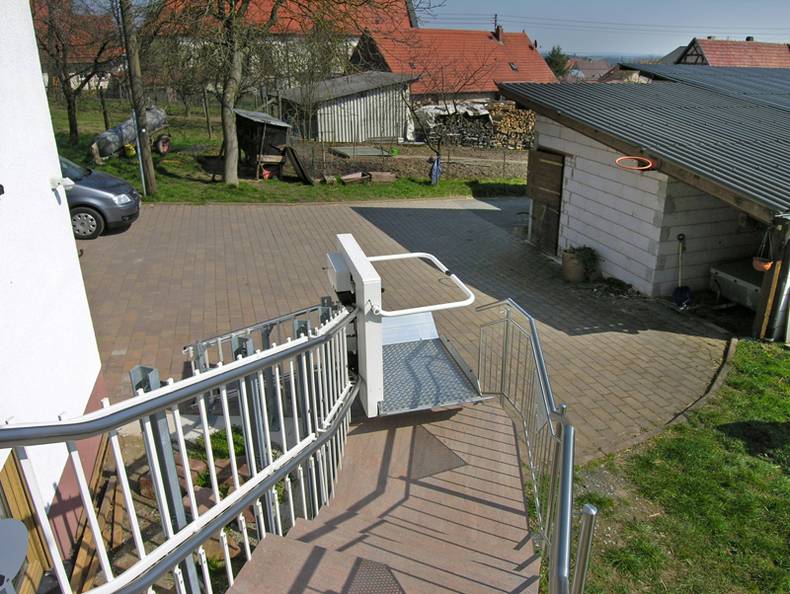
В конструкции подъемной платформы используется принципиально новое, запатентованное решение для передвижения платформы по направляющей магистрали.
Автономный, энергонезависимый фрикционный привод с полиуретановыми роликами обеспечивает перемещение подъемной платформы по абсолютно гладкой направляющей магистрали. Это делает перемещение подъемного устройства практически бесшумным, обеспечивает комфортное, мягкое движение и исключает износ направляющей магистрали.
Особенности конструкции:
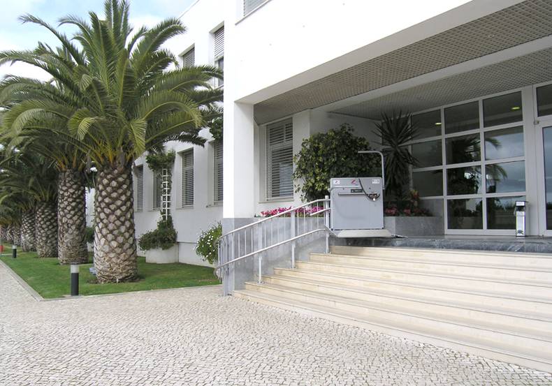
- Установка как внутри, так и снаружи здания;
- Полностью автоматическое управление;
- Непрерывная продолжительность работы в течение двух часов;
- Автоматическая зарядка на остановочных пунктах;
- Плавный пуск и остановка;
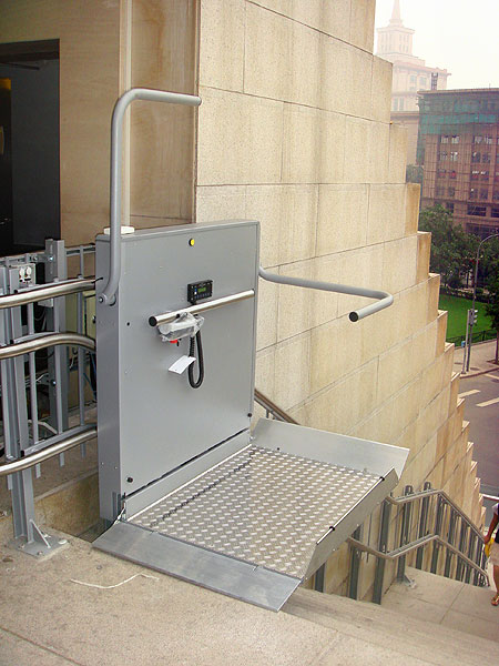
- Пульт дистанционного управления;
- Функциональный дисплей;
- Крепление направляющей магистрали на стойках или стене;
- Регулировка скорости в зависимости от траектории движения;
- Повторяет траекторию лестничного марша.
Безопасность:
- Звуковая сигнализация;
- Контур безопасности по периметру платформы;
- Ограничитель скорости и эксцентриковый ловитель;
- Датчик перегрузки;
- Контроль открытия шлагбаумов.
Источник
Наклонный подъёмник БК 320 (По сложной траектории)
Описание
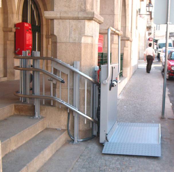
Подъёмная платформа БК 320 (Подъёмник) с наклонным перемещением предназначена для передвижения лиц с ограниченными возможностями вдоль лестничного марша по прямолинейной траектории.
В конструкции подъемной платформы используется принципиально новое, запатентованное решение для передвижения платформы по направляющей магистрали.
Автономный, энергонезависимый привод с полиуретановыми роликами обеспечивает перемещение подъемной платформы по абсолютно гладкой направляющей магистрали. Это делает перемещение подъемного устройства практически бесшумным, обеспечивает комфортное, мягкое движение и исключает износ направляющей магистрали.
Особенности конструкции:
- Установка как внутри, так и снаружи здания;
- Полностью автоматическое управление;
- Непрерывная продолжительность работы в течение двух часов;
- Автоматическая зарядка на остановочных пунктах;
- Плавный пуск и остановка;
- Пульт дистанционного управления;
- Функциональный дисплей;
- Крепление направляющей магистрали на стойках или стене.
Безопасность:
- Звуковая сигнализация;
- Контур безопасности по периметру платформы;
- Ограничитель скорости и эксцентриковый ловитель;
- Датчик перегрузки;
- Контроль открытия шлагбаумов.
Технические характеристики:
Источник
БАРАБАН КАБЕЛЬНЫЙ БК240, БК320. Паспорт БК ПС. Руководство по эксплуатации БК РЭ ЗАО «ИНЖЕНЕРНО-ТЕХНИЧЕСКИЙ ЦЕНТР «КРОС»
1 ЗАО «ИНЖЕНЕРНО-ТЕХНИЧЕСКИЙ ЦЕНТР «КРОС» БАРАБАН КАБЕЛЬНЫЙ БК240, БК320 Паспорт БК ПС Руководство по эксплуатации БК РЭ г. Ивантеевка 2013 год
2 1 ПАСПОРТ 1.ОБЩИЕ СВЕДЕНИЯ Барабаны кабельные БК240, БК320 изготавливается ЗАО «ИТЦ «КРОС», Россия, , г. Ивантеевка, Московская область, Санаторный проезд, д.1. Тел. (495) (41, 42), (49653) НАЗНАЧЕНИЕ И ОБЛАСТЬ ПРИМЕНЕНИЯ. 2.1.Назначение. Барабаны кабельные БК240 и БК320 предназначены для передачи электрических сигналов на оголовок телескопической стрелы подъемного крана или подъемника, например, на фару, фонарь, антенну устройства защиты от приближения к ЛЭП, ограничителю высоты подъема крюка, соединения с датчиками усилия и т.д. Барабаны кабельные БК240 и БК320 с дополнительным оборудованием предназначены для использования в качестве датчиков длины стрелы и угла наклона стрелы. Датчики имеют цифровой выход (интерфейс LIN) или аналоговый выход по напряжению (В), тип выходного сигнала оговаривается при заказе барабана Область применения. Стреловые самоходные краны: Краны — манипуляторы; Подъемники и др. 3. ТЕХНИЧЕСКАЯ ХАРАКТЕРИСТИКА. Таблица 1 Тип барабана БК Х_ БК Х_ БК Х_ БК Х_ Параметры Комплектация Х Диаметр обечайки, мм Ширина обечайки, мм Длина кабеля, м Рабочая длина сматывания кабеля, м Усилие натяжения кабеля, кг (max) не менее Кабель рабочий Приложение Сечение жил 0,5 0,5 0,5 6 Количество линий передачи, электрических сигналов 7 Транслируемое напряжение, 24DC 24DC 24DC В 8 Ток, А (не более) Количество щеток токосъемника 4 (8)* 4 (8)* 4 (8)* 10 Климатическое исполнение У1 У1 У1 по ГОСТ Степень защиты по ГОСТ IP54 IP54 IP Габаритные размеры Рис.1 Рис.2 Рис.3 13 Масса, кг 15 18,6 26,6 2 23
3 Приложение 2 Продолжение таблицы 1 Тип барабана БК Х_ БК Х_ БК Х_ БК Х_ Параметры Комплектация Х Датчик длины, наличие Интерфейс LIN 14.3 Диапазон сигнала, В Датчик угла, наличие Интерфейс LIN 15.3 Диапазон сигнала В 0-4 *В скобках по спецзаказу А-аналоговый выход 22
4 Приложение 1 Рис.5 4. КОМПЛЕКТ ПОСТАВКИ. Таблица 2 Наименование Обозначение Кол Примечание Барабан кабельный см раздел 6 1 Жгут с разъемом БК * 4-жильный БК * 7-жильный Разъем SP21/S4 4 контакта SP21/S7 7 контактов Паспорт БК ПС 1 Руководство по эксплуатации БК РЭ 1 Пломба Тара по заказу *По заказу 4 21
5 5. МАРКИРОВКА И ПЛОМБИРОВАНИЕ Маркировка. Маркировка барабана включает название и адрес предприятия, заводской номер и год выпуска, нанесенные на самоклеющийся шильдик, закрепленный на крышке барабана. Тип барабана и его комплектация указываются в паспорте Пломбирование. Комплектация 1 не пломбируется. Пломбирование комплектации 2,3 и 4 производится при изготовлении службой сервиса после настройки датчиков длины и угла наклона стрелы путем установки специальной чашки под винт в одном из мест крепления крышки наружной барабана. Чашка заполняется пластичным материалом. 20 5
6 6. СВИДЕТЕЛЬСТВО О ПРИЕМКЕ Барабан кабельный БК- зав. соответствует технической документации и признан годным для эксплуатации. Комплектация: Длина кабеля, м Рабочая длина сматывания, м Количество щеток, шт Настройка датчиков Датчик длины Номер датчика Прошивка 1 ДД (v2.2) hex 2 ДД (v2.2) hex 3 ДД (v2.2) hex 4 ДД (v2.2) hex Длина АЦП В Датчик угла Номер датчика в программе Угол АЦП В Дата выпуска.. Руководитель предприятия личная подпись (расшифровка подписи) Начальник ОТК М П 6 подпись (расшифровка подписи) 19 Приложение 1
7 7. ГАРАНТИЙНЫЕ ОБЯЗАТЕЛЬСТВА Изготовитель гарантирует соответствие барабана кабельного требованиям технической документации при соблюдении потребителем условий транспортирования, хранения, монтажа, технического обслуживания и эксплуатации Гарантийный срок хранения 6 месяцев со дня отгрузки потребителю Гарантийный срок эксплуатации устанавливается 18 месяцев со дня ввода в эксплуатацию, но не превышает 24 месяца со дня выпуска. Если барабан не был введен в эксплуатацию до истечения гарантийного срока хранения, началом гарантийного срока эксплуатации считается момент истечения гарантийного срока хранения Гарантийный срок продлевается на время от подачи рекламации до введения устройства в эксплуатацию после устранения недостатков предприятиемизготовителем. 7.5.Изготовитель несет гарантийную ответственность только при условии проведения пусконаладочных работ кабельного барабана специализированной организацией в соответствии с руководством по эксплуатации при наличии соответствующих отметок в паспорте (раздел 9) Изготовитель принимает в гарантийный ремонт изделие в целом только при наличии заполненного паспорта (раздел 9, 10, 11). 8. СВИДЕТЕЛЬСТВО ОБ ОТГРУЗКЕ. Барабан кабельный зав. упакован и отгружен в комплектности, указанной в разделе 4 паспорта. Упаковщик (расшифровка подписи) Отгрузку произвел (расшифровка подписи) М.П. 9. СВИДЕТЕЛЬСТВО ОБ УСТАНОВКЕ. Барабан кабельный зав. 18 Приложение 1 смонтирован на кране модели, зав. монтаж произведен наименование организации, производившей установку, дата Подписи лиц, производивших установку (расшифровка подписи) дата 7
8 10. СВЕДЕНИЯ О ТЕХНИЧЕСКОМ ОБСЛУЖИВАНИИ И НАСТРОЙКЕ Техническое обслуживание. Дата Содержание ТО Подпись Дата очередного ТО РУКОВОДСТВО ПО ЭКСПЛУАТАЦИИ 8 17 Приложение 1
9 16 Приложение 1 1. СОСТАВ ИЗДЕЛИЯ (Рис. 5) Кабельный барабан состоит из следующих частей: 1) обойма с ребордами для намотки кабеля и пружинным приводом; 2) узел крепления барабана; 3) кабель рабочий; 4) жгут с разъемом; 5) кабель соединительный с разъемом; 6) щеточный узел; 7) модуль измерения длины; плата угла наклона Позиции 7 и 8 присутствуют только в комплектациях 2, 3, В зависимости от типа барабана (см. таблицу 1 паспорта) обойма с ребордами (1) различается по диаметру и ширине. В барабанах БК240-2 рабочий кабель размещается на обойме диаметром 240мм и шириной 132 мм. В барабанах БК320-1 диаметр обоймы 320мм и ширина 94 мм. Обойма барабана БК320-3 имеет ширину 163 мм. Привод барабанов осуществляется ленточной пружиной (2), закрепленной с одной стороны к обойме с другой к валу (12). Барабан БК320-3 имеет две пружины, работающие последовательно Узел крепления барабана (3), представляет собой скобу, закрепленную гайкой на валу (12). На скобе имеется метка, определяющая верхнее положение скобы. Скоба болтами крепится к двум платикам, привариваемым к стреле Кабель рабочий (4) гибкий, морозостойкий имеет четыре медных жилы сечением 0,5мм со стальной жилой для предотвращения его вытягивания под нагрузкой. Допустимый ток 3А, напряжение 24В. Длина кабеля, указанная в таблице 1 паспорта, соответствует типовой комплектации. В соответствии с заказом длина кабеля и рабочая длина может быть увеличена (специальное исполнение) Кабель соединительный (5) через клеммники соединен с выходным кабелем (6) и выходами плат измерения длины стрелы и угла наклона стрелы (при их наличии). В зависимости от комплектации барабана разъем кабеля имеет 4 или 7 контактов Выходной кабель служит для подсоединения к электросхеме машины. При заказе оговаривается длина кабеля. По умолчанию поставляется разъем без кабеля. Рабочий чертеж кабеля дан в приложении Щеточный узел (8) состоит из четырех щеток (7), соединяющих через кольца токосъемника рабочий кабель (4) с кабелем выходным (5). По заказу может быть установлено 8 щеток (две щетки на одно кольцо токосъемника) специальное исполнение. Установка восьми щеток рекомендуется в случае передачи по рабочему кабелю цифровой информации (LIN, RS-485 и др.) Модуль для измерения длины (стрелы) состоит из зубчатого диска (10) (40 зубьев) и платы (9), преобразующей сигналы «1» и «0», получаемые с отопар, расположенных на плате, в цифровой сигнал (LIN) или напряжение, которое меняется от 0 до 5В в зависимости от регистрируемой длины. Плата имеет выходы для установки «нуля» (начало отсчета «0») и «единицы» (конец отсчета «1», соответ- 9
10 ствующей 100% измеряемой длины). Выходы установок «нуля» и «единицы» выведены на кнопки (13) и (14), расположенные на клеммнике, на котором производятся соединения в соответствии со схемами электрических соединений (см. раздел 3). Кнопка «нуль» (13) дублируется на кабеле выходном и кабеле соединительном (контакт 5). При соединение контакта 5 с контактом «-» происходит обнуление показаний, что позволяет всегда возвращаться к началу отсчета при установке концевика, контакты которого замыкаются при минимальной длине (стрелы). Кнопкой (14), соединенной с выходом «1», устанавливается конец отсчета в соответствии с заданной измеряемой длиной (стрелы) Плата угла наклона (стрелы) (11) позволяет измерять угол наклона в пределах от -30 до +90. При измерении горизонтального положения на аналоговом выходе напряжение 1В, при угле наклона -30, напряжение равно «0». При угле 90 — напряжение 4В. При положении крана, соответствующем горизонтальному положению (стрелы), для получения на выходе напряжения 1В необходимо при включенном питании кратковременно нажать кнопку (15) на плате. Расположение кнопок показано на рис МОНТАЖ И НАСТРОЙКА ИЗДЕЛИЯ Установка барабана производится путем крепления скобы болтами М8 на платиках, которые привариваются к вертикальной стенке (стрелы) в горизонтальном положении, метка скобы должна быть вверху (рис.4). Закрепление рабочего кабеля при его сматывании с обечайки барабана производится таким образом, чтобы в крайнем выдвинутом положении стрелы запас по длине сматывания кабеля составлял не менее 1-1,5 витка, а запас по повороту барабана в сторону наматывания составлял 2 оборота. При минимальной длине стрелы контакты «0» и «1» через концевик должны быть замкнуты (см. схемы стр.16,17, 18) Настройка Барабан комплектаций 2,3,4 поставляется настроенным в соответствии с параметрами, указанными в разделе 6 паспорта. Комплектация 1 не настраивается. Настройка требуется, если необходимо изменить параметры настройки или они по какой-либо причине изменены Настройка модуля измерения длины. Модуль измерения длины применяется в комплектациях 2 и 4 (табл.1 паспорта). Для настройки модуля открываем доступ к модулю, для чего снимаем наружную реборду (БК240) или крышку барабана (БК320-1; БК320-3). Устанавливаем минимальную длину (стрелы), включаем питание и на клеммнике нажимаем кнопку «0» (13) измеряем напряжение Uвых. Оно должно равняться нулю. Вместо кнопки «0» может быть выполнено замыкание контактов концевого выключателя, контакты которого находятся в замкнутом положении (14) при сложенной стреле. При установке максимальной длины (стрелы) нажимаем кнопку «1», напряжение Uвых=5В. Настройка модуля измерения длины завершена. Устанавливаем реборду или крышку в исходное положение Настройка платы угла наклона (стрелы). Приложение
11 ны стрелы 4. Затруднено вращение барабана 5.Не наматывается кабель 4.**Загустение смазки в пружине. Коррозия. 5. Сломана пружина (ВО) 4.* Направить в ремонт. 5.*Направить в ремонт *-Ремонт барабана производится: 1. ЗАО «ИТЦ «КРОС» по адресу: Россия, , Московская область, г.ивантеевка, Санаторный проезд, д.1, тел./факс: (495) , , , (49653) , (49653) (факс). 2. Другими организациями по представлению ЗАО «ИТЦ «КРОС». **Данный вид неисправности вызван отсутствием технического обслуживания. Гарантийный ремонт при этом не производится. 7. Правила хранения. Комплект поставки барабана в транспортной таре изготовителя допускает хранение в течение 6-ти месяцев при следующих условиях: в закрытых сухих помещениях с естественной вентиляцией по ГОСТ по 1-3 группам; отсутствие в помещении хранения паров кислот, щелочей, а также газов, вызывающих коррозию. 8. Транспортирование На железнодорожных платформах ящики необходимо транспортировать в контейнерах, в случае применения других средств необходимо ящики накрыть водонепроницаемой пленкой Расстановка и крепление в транспортных средствах ящиков должны обеспечивать их устойчивое положение, исключить возможность их падения. 9. Утилизация. При утилизации должны быть отделены печатные платы, цветные металлы: провода, разъемы. Остальные элементы являются ломом черных металлов. Приложение 1 Плата угла наклона стрелы устанавливается в комплектациях 3 и 4. Для настройки платы открываем доступ к плате (п.2.2), устанавливаем стрелу в горизонтальное положение и при включенном питании на плате нажимаем кнопку 15 (см. п. 1.8). Настройка завершена. Напряжение на выходе Uвых2=1В 3.СХЕМЫ ЭЛЕКТРИЧЕСКИХ СОЕДИНЕНИЙ. В зависимости от комплектации барабана и типа выходного сигнала (LIN или выход по напряжению) выбирается одна из схем электрических соединений (приложение 1). Нужно иметь ввиду, что кабельные барабаны с цифровым выходом сигнала (LIN) преобразуются на выход по напряжению только изменением схемы электрических соединений. 4. Указание мер безопасности. Для обеспечения безопасной работы подъемного устройства, оборудованного кабельным барабаном, необходимо: знать и соблюдать меры безопасности, предусмотренные для подъемного устройства не находиться рядом с барабаном при сматывании кабеля с обечайки барабана не препятствовать вращению барабана, если при натяжении кабеля он вырвался из рук своевременно проводить техническое обслуживание. 5. Техническое обслуживание Общие указания Техническое обслуживание кабельного барабана обеспечивает его работоспособность в течение всего срока службы. Периодичность обслуживания, установленная настоящим руководством, должна соблюдаться на протяжении всего срока службы. Сведения о техническом обслуживании заносятся в паспорт барабана. Проведение технического обслуживания является обязательным условием для выполнения изготовителем гарантийных обязательств Виды и периодичность технического обслуживания. Техническое обслуживание барабана подразделяется на следующие виды: ежесменное техническое обслуживание (ЕО) проводится каждую смену перед началом работы; внеочередное обслуживание (ВО); сезонное техническое обслуживание (СО) проводится два раза в год после расконсервации ограничителя, а также после перерыва в эксплуатации более шести месяцев Подготовка к техническому обслуживанию
12 Для проведения технического обслуживания своевременно подготовьте требуемые материалы, инструменты, приборы. Перед проведением технического обслуживания выключить электропитание крана. Подключение приборов к электроразъемам блока преобразователя допускается только при выключенном электропитании Порядок технического обслуживания Ежесменное техническое обслуживание. Ежесменное техническое обслуживание производится машинистом крана. Перечень работ при ЕО приведен в табл.5.1. Таблица 5.1 Содержание работ Технические требования Методы контроля, приборы и материалы Проверка функционирования Осмотреть барабан. Проверить навивку кабеля. Навивка должна быть ровной. При необходимости уложить кабель. При наличии снега или льда на барабане и кабеле удалить. Проверить включение контакта обнуления при сложенной стреле. 12 Визуально, щетка, ветошь Внеочередное техническое обслуживание. Внеочередное техническое обслуживание проводится между сезонными техническими обслуживаниями при необходимости устранения недостатков, выявленных в процессе эксплуатации. Таблица 5.2 Содержание работ Технические требования Методы контроля и материалы Проверка функционирования Устранение сбоев в передаче сигналов Выполнить работы ЕО Снять пломбу и крышку барабана. Удалить влагу (при наличии). Удалить пыль (при наличии). Проверить состояние щеток и колец токосъемника. Протереть кольца токосъемника спиртом. Проверить крепление проводов, отсутствие коррозии клеммных соединений. Зачистить контакты (при необходимости) Сезонное техническое обслуживание. Визуально, щетка, ветошь Отвертка, гаечный ключ S=10, ветошь, щетка Салфетка медицинская, пропитанная спиртом Сезонное техническое обслуживание производится наладчиком приборов безопасности. Перечень работ при СО приведен в таблице 5.3. Таблица 5.3. Содержание работ Технические требования Методы контроля, приборы и материалы Проверка функцио- Выполнить работы ЕО См. таблицу 5.2 нирования Проверка параметров настройки Выполнить работы ВО Проверить правильность показаний датчика длины стрелы. Проверить правильность показаний датчика угла. Провести настройку (при необходимости). 13 Милливольтметр 6.Указания по ремонту и устранению неисправностей При обнаружении неисправностей во время работы или при проведении технического обслуживания должна быть определена причина неисправности, а барабан или линии связи должны быть подвергнуты ремонту Перечень основных неисправностей и способов их устранения приведен в таблице 6.1. При диагностировании неисправностей рекомендуется пользоваться таблицей 5.2, 5.3. Состояние системы При включении питания При работе Признак неисправности 1. Показания датчика длины на вторичном приборе не соответствуют действительным 2. Показания датчика угла на вторичном приборе не соответствуют действительным 3. Пропадание сигналов с линий связи при изменении дли- Возможные причины 1.1. Спадание витка кабеля с барабана 1.2. Не происходит «обнуление» показаний датчика при минимальной длине стрелы 2.Неисправная установка кронштейна датчика угла 3.Загрязнение щеток и колец токосъемника Таблица 6.1 Способы устранения 1.1. Установить кабель на место. Провести настройку датчика длины по п Восстановить «обнуление» датчика длины. 2. При горизонтальной установке стрелы кронштейн датчика угла должен находиться внизу по вертикали. Произвести установку кронштейна и нормировку датчика угла по п Произвести внеочередное техническое обслуживание
Источник
1. Contents
1.
Contents…………………………………………………………………………………………………………………….. Page 2
2.
Meaning of symbols and glossary of terms………………………………………………………………….. Page 4
3.
Warranty…………………………………………………………………………………………………………………….. Page 5
4.
General safety instructions …………………………………………………………………………………………. Page 6
5.
Summary of HIRO inclined lifts
5.1
HIRO 320 — turning platform lift system………………………………………………………………….. Page 9
5.2
HIRO 350 — straight platform lift system……………………………………………………………….. Page 10
5.3
HIRO 360 — turning lowerable platform lift system…….. ………………………………………….. Page 11
5.4
HIRO 370 — turning lowerable platform lift system…….. ………………………………………….. Page 12
5.5
Platform components and accessories ………………………………………………………………….. Page 13
5.6
Safety devices……………………………………………………………………………………………………. Page 15
6.
Operation of HIRO inclined lifts
6.1
Requirements for initial operation …………………………………………………………………………. Page 17
6.2
Key-operated systems ………………………………………………………………………………………… Page 19
6.3
Calling the wheelchair lift and riding (lift with key-operated platform control and remote
control) ……………………………………………………………………………………………………………… Page 21
6.3.1
Call platform — from downstairs ………………………………………………………………….. Page 21
6.3.2
Riding upstairs ………………………………………………………………………………………… Page 24
6.3.3
Call platform — from upstairs ………………………………………………………………………. Page 28
6.3.4
Riding downstairs…………………………………………………………………………………….. Page 30
6.4
Calling the wheelchair lift and riding (lift with ON/OFF key) ………………………………………. Page 34
6.4.1
Call platform — from downstairs ………………………………………………………………….. Page 34
6.4.2
Riding upstairs ………………………………………………………………………………………… Page 36
6.4.3
Call platform — from upstairs ………………………………………………………………………. Page 43
6.4.4
Riding downstairs…………………………………………………………………………………….. Page 45
6.5
Mounting and dismounting the wheelchair lift at intermediate stops…………………………… Page 52
6.6
Deactivating the system ………………………………………………………………………………………. Page 54
6.7
Display ……………………………………………………………………………………………………………… Page 55
6.8
Maintenance and cleaning instructions ………………………………………………………………….. Page 56
7.
Dealing with faults
7.1
Emergency operation ………………………………………………………………………………………….. Page 57
7.1
Moving the platform: Model with hand wheel ………………………………………………. Page 57
7.1
Moving the platform: Model with electrically operated emergency control……….. Page 59
7.2
Manually lowering the HIRO 360 and HIRO 370 platform lift system ……………… Page 60
7.2
Emergency evacuation………………………………………………………………………………………… Page 61
7.3
Battery change …………………………………………………………………………………………………… Page 64
7.4
Troubleshooting in case of malfunctions………………………………………………………………… Page 65
8.
Maintenance……………………………………………………………………………………………………………… Page 72
9.
Assembly and disassembly ………………………………………………………………………………………. Page 73
2
Your task is not to seek for love, but merely to seek and find all the barriers within yourself that
133 downloads
2783 Views
602KB Size
Recommend Stories
I-320 Instruction Manual
Every block of stone has a statue inside it and it is the task of the sculptor to discover it. Mich
Installation Instruction
Learn to light a candle in the darkest moments of someone’s life. Be the light that helps others see; i
HIRO III
Goodbyes are only for those who love with their eyes. Because for those who love with heart and soul
Подъемные платформы данного типа предназначены для тех мест, где есть необходимость преодоления поворотов, очень удобно использовать криволинейные направляющие рельсы со сложной траекторией движения. Чаще всего они устанавливаются в подъездах жилых домов, в подземных переходах. Качественно выполненая конструкция из нержавеющей стали, состоящая из двух труб, соединяющихся поперечинами – выполняет функцию ограждения- придает чувство надежности и безопасности. Для вызова подъемной платформы используется дистанционная настенная радио-кнопка. Платформа доезжая до остановки замедляет свой ход что служит дополнительным источником комфорта.
Мы так же можем Вам предложить подъемную платформу итальянского производителя Vimec модели V65.
Вас интересует стоимость подъемника, возможность установки универсальной платформы для всех типов инвалидных колясок и инвалидных кресел, включая электрические, дополнительная информация или скидка на оборудование? Звоните. Инвалиды-колясочники и люди с ограниченными возможностями нуждаются в средствах реабилитации.
ГАЛЕРЕЯ