инструкцияHyundai H-1 Grand Starex (2010)

РУКОВОДСТВО ПО
ЭКСПЛУАТАЦИИ
Эксплуатация
Техническое обслуживание
Технические характеристики
Вся информация в настоящем Руководстве по эксплуатации приведена по
состоянию на момент публикации.
Компания Hyundai оставляет за собой право в любое время вносить изменения
в рамках постоянно действующей программы модернизации продукции.
Настоящее Руководство применимо для всех моделей автомобилей Hyundai и
содержит описания как дополнительного, так и стандартного оборудования, а
также соответствующие пояснения. Поэтому в данном Руководстве Вы сможете
обнаружить материалы, не имеющие отношения к конкретной модели Вашего
автомобиля.
Посмотреть инструкция для Hyundai H-1 Grand Starex (2010) бесплатно. Руководство относится к категории автомобили, 2 человек(а) дали ему среднюю оценку 7.6. Руководство доступно на следующих языках: русский. У вас есть вопрос о Hyundai H-1 Grand Starex (2010) или вам нужна помощь? Задайте свой вопрос здесь
Главная
Не можете найти ответ на свой вопрос в руководстве? Вы можете найти ответ на свой вопрос ниже, в разделе часто задаваемых вопросов о Hyundai H-1 Grand Starex (2010).
Как перевести мили в километры?
1 миля равна 1,609344 километрам, а 1 километр — 0,62137119 милям.
Где я могу узнать идентификационный номер транспортного средства Hyundai?
Место размещения идентификационного номера транспортного средства зависит от марки и типа транспортного средства. Номер может быть выбит на раме транспортного средства или указан на номерном знаке. Чтобы узнать место расположения идентификационного номера транспортного средства лучше всего ознакомиться с руководством по эксплуатации Hyundai H-1 Grand Starex (2010).
Что такое идентификационный номер транспортного средства (VIN)?
Идентификационный номер транспортного средства — уникальный для каждого транспортного средства идентификационный номер. Аббревиатура VIN расшифровывается как «Vehicle Identification Number» (Идентификационный номер транспортного средства).
Когда транспортному средству Hyundai требуется техническое обслуживание?
Регулярное техническое обслуживание необходимо всем транспортным средствам. С информацией о том, как часто необходимо проходить техническое обслуживание и чему именно стоит уделять особое внимание можно ознакомиться в инструкции по техническому обслуживанию. Как правило, транспортное средство требует технического обслуживания каждые 2 года или 30 000 километров пробега.
Когда следует заменять тормозную жидкость на Hyundai?
Тормозную жидкость рекомендуется менять каждые два года.
В чем разница между топливом E10 и E5?
В топливе E10 содержится до десяти процентов этанола, в то время как в E5 содержится менее пяти процентов. Соответственно, топливо E10 менее вредит окружающей среде.
Одна или несколько дверей не открываются изнутри. Что мне делать?
Скорее всего, замок оснащен защитой от детей и поэтому не может быть открыт изнутри. Процедура открытия замка с защитой от детей зависит от марки и типа замка.
Автомобильный радиоприемник не включается, что делать?
Если автомобильный радиоприемник не включен, на него не будет подаваться питание. Убедитесь, что красный провод подключен к контактному источнику питания, а желтый провод — к источнику питания постоянной мощности.
Инструкция Hyundai H-1 Grand Starex (2010) доступно в русский?
Да, руководствоHyundai H-1 Grand Starex (2010) доступно врусский .
Не нашли свой вопрос? Задайте свой вопрос здесь


Купить полную версию книги
>
1. ТЕХНИЧЕСКАЯ ИНФОРМАЦИЯ АВТОМОБИЛЯ
СЕРИЙНЫЙ НОМЕР АВТОМОБИЛЯ (VIN)
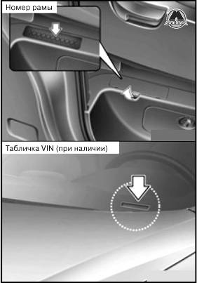
Серийный номер автомобиля это номер, который используется при регистрации Вашего транспортного средства и применяется во всех правовых случаях, относящихся к вопросам прав собственности на автомобиль и т. д.
СЕРТИФИКАЦИОННАЯ ТАБЛИЧКА
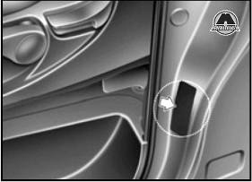
Сертификационная табличка находится на внешней стороне средней стойки со стороны водителя (или переднего пассажира) и содержит серийный номер автомобиля (VIN).
ТАБЛИЧКА ТЕХНИЧЕСКИХ ХАРАКТЕРИСТИК/ЗНАЧЕНИЙ ДАВЛЕНИЯ В ШИНАХ
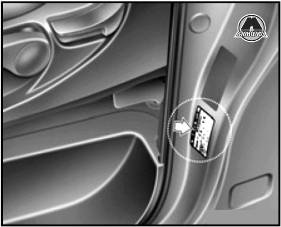
Установленные на Вашем автомобиле шины выбраны для обеспечения наилучших характеристик управляемости автомобиля. Табличка технических характеристик шин находится на внешней панели средней стойки со стороны водителя и содержит информацию о рекомендуемом давлении в шинах Вашего автомобиля.
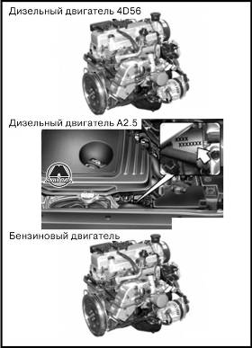
Серийный номер двигателя выбит на блоке цилиндров, как показано на рисунке.
| Параметр | мм |
| Общая длина | 5125 |
| Общая ширина | 1920 |
| Общая высота | 1925 |
| Колея передних колес | 1685 |
| Колея задних колес | 1660 |
| Колесная база | 3200 |
Примечание:
Указанные выше размеры приведены для 12-местного/8-местного автомобиля.
| Тип лампы | Мощность, Вт |
| Фары (ближний свет/дальний свет) | 55/55 |
| Передние указатели поворотов | 21 |
| Тип лампы | Мощность, Вт |
| Габаритный фонарь | 5 |
| Боковой повторитель указателя поворотов* | 5 |
| Передние противотуманные фары* | 27 |
| Задняя противотуманная фара* | 21 |
| Стоп-сигнал и задний габаритный фонарь | 21/5 |
| Задние указатели поворота | 21 |
| Фонари заднего хода | 16 |
| Высокорасположенный повторитель стоп-сигнала | 5 |
| Лампы освещения номерного знака | 5 |
| Центральная потолочная лампа | 10 |
| Лампа багажного отсека* | 10 |
| Лампа освещения подножки* | 5 |
Примечание:
* При наличии.
| Наименование | Размер шины | Размер колеса | Давление в шине, бар (кПа) | Момент затяжки гайки крепления колеса кг-м (Н-м) | |||||
| Универсал | Минивэн | ||||||||
| Номинальная нагрузка | Максимальная нагрузка | ||||||||
| Передняя | Задняя | Передняя | Задняя | Передняя | Задняя | ||||
| Полноразмерная шина | 215/70R16 | 6.5Jx16 | 2,9 (290) | 3,25 (325) | 2,9 (290) | 3,5 (350) | 2,9 (290) | 3,5 (350) | 9-11 (88-107) |
Примечание:
* Номинальная нагрузка — до трех человек.
РЕКОМЕНДУЕМЫЕ СМАЗОЧНЫЕ МАТЕРИАЛЫ И ИНФОРМАЦИЯ ОБ ОБЪЕМАХ
Для достижения оптимального режима работы двигателя и трансмиссии, а также увеличения их сроков службы, используйте только качественные смазочные материалы. Качественные смазочные материалы также влияют на эффективность работы двигателя и снижают расход топлива. На Вашем автомобиле рекомендуется использовать следующие смазочные материалы и жидкости.
| Смазочный материал | Объем | Классификация | ||
| Моторное масло*1*2 (слив и заливка) Рекомендуется HELiX Motor oils | Дизельный двигатель*3 | А2.5 | 7,4/(7,82 US) | VGT*3: API Service CH-4 или выше, ACEA B4 WGT*4: API Service CF-4 или выше, ACEA B4 |
| 4D56 | 5,4/(5,71 US) | API Service CF-4 или выше, ACEA B2 или ВЗ | ||
| Бензиновый двигатель | 4,3/(4,54 US) | API Service SJ, SL или выше, ILSAC GF-3 или выше | ||
| Масло механической коробки передач | Дизельный двигатель А2.5 | 3,2/(3,38 US) | API Service GL-4 (SAE 75W/85) | |
| Дизельный двигатель 4D56/ Бензиновый двигатель | 1,95/(2,06 US) | |||
| Жидкость автоматической коробки передач | Дизельный двигатель А2.5 | 10,0/(10,60 US) | APOLLOILATF RED-1 | |
| Дизельный двигатель 4D56/ Бензиновый двигатель | 8,0/(8,45 US) | CASTLE AUTO FLUID T-IV, DIAMOND ATFSP-I | ||
| Усилитель рулевого управления | 0,9-1,0/(0,95-1,06 US) | PSF-3 | ||
| Жидкость системы охлаждения | Универсал | 13/(13,74 US) | Смесь антифриза и воды (Охлаждающая жидкость на основе этиленгликоля для алюминиевого радиатора) | |
| Минивэн | 10/(10,57 US) | |||
| Тормозная жидкость | 0,7-0,8/(0,7-0,8 US) | FMVSS116 DOT-3 или DOT-4 | ||
| Масло редуктора заднего моста | 1,8-2,4/(1,9-2,54 US) | Зона умеренного климата (-30 °С~30 °С): APIGL-4 (SAE90). Зона жаркого климата (свыше +30 °С): APIGL-4 (SAE140). Зона холодного климата (ниже -30 °С): API GL-5 (SAE 80). |
||
| Топливо | 75/(79,25 US) | — |
Примечание:
*1 Смотрите рекомендованный индекс вязкости по SAE.
*2 В настоящее время в наличии имеется масло с маркировкой Energy Conserving Oil (энергосберегающее моторное масло). Помимо прочих положительных эффектов, применение такого масла способствует экономии расхода топлива за счет сокращения потребления топлива, необходимого для преодоления трения деталей двигателя. Зачастую эти улучшения трудно оценить при ежедневном вождении, однако суммарная экономия средств и энергии за год оказывается внушительной.
*3 W.G.T — турбонагнетатель с перепускным клапаном.
*4 V.G.T — турбонагнетатель изменяемой геометрии.
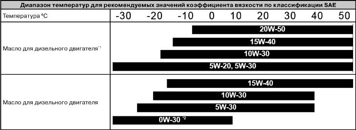
РЕКОМЕНДУЕМЫЕ ЗНАЧЕНИЯ КОЭФФИЦИЕНТА ВЯЗКОСТИ ПО КЛАССИФИКАЦИИ SAE
ВНИМАНИЕ
Обязательно убедитесь в чистоте пространства вокруг крышки любой заливной горловины, сливного отверстия и масляного щупа перед проверкой уровня масла или его заменой. Это особенно важно при эксплуатации транспортного средства в пыльных и загрязненных условиях и при езде по грунтовым дорогам. Очистка крышки и щупа предотвратит попадание пыли и песка в двигатель и другие механизмы, которые могут быть повреждены.
Вязкость моторного масла влияет на расход топлива и на эксплуатацию в холодную погоду (запуск двигателя и подача масла). Моторное масло низкой вязкости обеспечивает лучший уровень экономии топлива и лучшую работу двигателя в холодную погоду, а масло с высоким коэффициентом вязкости необходимо для требуемого уровня смазки двигателя в жарких условиях. Использование масел со значениями коэффициентов вязкости, отличными от рекомендуемых, может привести к выходу двигателя из строя. При выборе типа масла, принимайте во внимание диапазон температур, в котором будет эксплуатироваться Ваш автомобиль до следующей замены масла. Выбирайте рекомендуемые значения коэффициента вязкости из таблицы.
Примечание:
*1 Для лучшей экономии топлива рекомендуется использовать моторное масло с коэффициентом вязкости по классификации SAE 5W-20, 5W-30 (API SJ, SL/ILSAC GF-3). Однако если данные марки масел недоступны в стране эксплуатации Вашего автомобиля, выбирайте подходящее масло, руководствуясь табличными значениями коэффициентов вязкости.
*2 Предназначено для использования в условиях крайне низких температур, его применение ограничено условиями эксплуатации и географическим положением (особенно не рекомендуется длительная эксплуатация с максимальной нагрузкой и эксплуатация на высоких скоростях).
Loading
Книга по устройству, тех. обслуживанию и ремонту Старекса.
-

Serj - Модератор

- Сообщений: 14926
- Зарегистрирован: 29 июл 2010, 07:38
- Откуда: Москва
- Благодарил (а): 969 раз.
- Поблагодарили: 3780 раз.
- Моя машина: H-1, 2007г, D4BH, длинный, 2wd, МКПП и Бобёр 4WD
- гос. номер: е888кх
- Населённый пункт: Москва, ЮАО
-
- Отправить письмо пользователю Serj


- Информация
- Цитата
Re: Книга по устройству, тех. обслуживанию и ремонту Старекс
Сообщение: №103 ![]() zero » 12 мар 2015, 19:42
zero » 12 мар 2015, 19:42
Есть бумажные книжки:
- Hyundai STAREX / Н-1 1998-07 диз. D4BH(2,5), D4CB(2,5 CRDi), D4BF(2,5), D4BB(2,6) Ремонт.Экспл.ТО
- Mitsubishi дизельные двигатели 4D56/4D56EFI/4D56DI-D(Common Rail)(2,5) и Hyundai &Kia D4BF/D4BH TCI/COVEC-F(2,5) серия ПРОФЕССИОНАЛ Диагност.Ремонт.ТО
Могу отсканировать, если кому интересно.
- zero
- Информация
- Цитата
Re: Книга по устройству, тех. обслуживанию и ремонту Старекс
Сообщение: №106 ![]() zero » 12 мар 2015, 19:49
zero » 12 мар 2015, 19:49
Klopius писал(а):интересно!
Обе интересны?
Klopius писал(а):а можешь одним файлом? (ну, чтоб не отдельными картинками было)
Думаю, да.
- zero
- Информация
- Цитата
Re: Книга по устройству, тех. обслуживанию и ремонту Старекс
Сообщение: №109 ![]() zero » 12 мар 2015, 19:58
zero » 12 мар 2015, 19:58
Usach писал(а):Первая у нас есть ,в этой теме
Я знаю. Тут обложка другая ![]()
- zero
- Информация
- Цитата
Re: Книга по устройству, тех. обслуживанию и ремонту Старекс
Сообщение: №112 ![]() zero » 12 мар 2015, 20:06
zero » 12 мар 2015, 20:06
Klopius писал(а):
Usach писал(а):Первая у нас есть ,в этой теме
та, что отдельными фотками?
Она одним файлом же. Или я что-то не понял?
Usach писал(а):Не,ну если сможешь сделать более качественно,и время на это есть-то делай

Я имел в виду, что обложка другая -> издание другое -> чисто теоретически могли поменять не только обложку.
Начну, пожалуй, с двигателей. А там посмотрим.
- zero
- Вынести предупреждение
- Информация
- Цитата
Re: Книга по устройству, тех. обслуживанию и ремонту Старекс
Сообщение: №113 ![]() Usach » 12 мар 2015, 20:09
Usach » 12 мар 2015, 20:09
zero писал(а):Я имел в виду, что обложка другая -> издание другое -> чисто теоретически могли поменять не только обложку.
Начну, пожалуй, с двигателей. А там посмотрим.
То же издание,Легион.И страниц одинаково,400.Движки давай 
-

Usach - Соратник Клуба
- Сообщений: 6968
- Зарегистрирован: 21 янв 2011, 00:55
- Благодарил (а): 777 раз.
- Поблагодарили: 2654 раз.
- Моя машина: 2006,D4CB,4WD,AKПП был
- гос. номер: хХХХхх07
- Населённый пункт: нальчик 98% краснодар 2%
-
- Отправить письмо пользователю Usach


- Вынести предупреждение
- Информация
- Цитата
Хендай H1/Старекс до 2007 онлайн руководство, схемы
Сообщение: №114 ![]() Shashvel » 18 мар 2015, 00:24
Shashvel » 18 мар 2015, 00:24
Дорогие клубни! Нашел сей ресурс с онлайн руководством по ремонту в двух видах на одной странице, так же на странице ниже есть ссылка для скачивания 57,27 МБ.
http://vnx.su/content/avto/hyundai/h1.html
Hyundai H1 / Starex и H-200 / Satellite с бензиновыми четырехтактными инжекторными двигателями: четырехцилиндровый 16-клапанный рядный модели I4 DOHC 110 л.с./80,9 кВт рабочим объемом 2,4 л 2351 см³ и с дизельными двигателями: 2.5 л 2467 см³ TCI/TC R4 OHC 8V 80 л.с./58,8 кВт и 2.6 л 2607 см³ N/A R4 OHC 8V 85 л.с./62,5 кВт Руководство по эксплуатации и ремонту, цветные электросхемы. Хундай Эйч 1 / Старекс и Эйч-200 / Сателлит модели выпуска с 2000 года
О Книге
Название: Hyundai H1 / Starex и H-200 / Satellite Руководство по ремонту и эксплуатации, цветные электросхемы.
Бензиновые четырехтактные инжекторные двигатели: четырехцилиндровый 16-клапанный рядный модели I4 DOHC 110 л.с./80,9 кВт рабочим объемом 2,4 л 2351 см³ и с дизельными двигателями: 2.5 л 2467 см³ TCI/TC R4 OHC 8V 80 л.с./58,8 кВт и 2.6 л 2607 см³ N/A R4 OHC 8V 85 л.с./62,5 кВт.
Выпуск с 2000 года.
Серия: «Ремонт»
Год издания: 2007
Автор: Коллектив авторов
Издательство: «Ассоциация независимых издателей»
Формат: PDF
Страниц в книге: 440
Размер: 57,27 МБ
Язык: Русский
Количество электросхем: 54
У вас нет доступа для просмотра вложений в этом сообщении.
-
Shashvel получил благодарность от: alexx143, arival52
-

Shashvel - Местный
- Сообщений: 56
- Зарегистрирован: 26 ноя 2014, 22:25
- Откуда: Краснодар
- Благодарил (а): 6 раз.
- Поблагодарили: 13 раз.
- Моя машина: 2011, CRDI, 2WD, АКПП Черный
- Населённый пункт: Краснодар
-
- Отправить письмо пользователю Shashvel


- Вынести предупреждение
- Информация
- Цитата
Re: Книга по устройству, тех. обслуживанию и ремонту Старекс
Сообщение: №115 ![]() Serj » 18 мар 2015, 08:54
Serj » 18 мар 2015, 08:54
Обложка другая, а внутри лежит чёрная монолитовская книжка — она уже есть тут.
-
Serj - Модератор
- Сообщений: 14926
- Зарегистрирован: 29 июл 2010, 07:38
- Откуда: Москва
- Благодарил (а): 969 раз.
- Поблагодарили: 3780 раз.
- Моя машина: H-1, 2007г, D4BH, длинный, 2wd, МКПП и Бобёр 4WD
- гос. номер: е888кх
- Населённый пункт: Москва, ЮАО
-
- Отправить письмо пользователю Serj
- Вынести предупреждение
- Информация
- Цитата
Re: Книга по устройству, тех. обслуживанию и ремонту Старекс
Сообщение: №118 ![]() Ren@ » 22 окт 2015, 11:51
Ren@ » 22 окт 2015, 11:51
-

Ren@ - Местный
- Сообщений: 1335
- Зарегистрирован: 22 авг 2012, 17:51
- Благодарил (а): 111 раз.
- Поблагодарили: 161 раз.
- Моя машина: STAREX 2000, D4BH, 4WD, МКПП, SVX, 905-102
STAREX 2005, D4CB, 4WD, АКПП, GOLD, 455-102 - Населённый пункт: УФА
-
- Отправить письмо пользователю Ren@
- Вынести предупреждение
- Информация
- Цитата
Re: Книга по устройству, тех. обслуживанию и ремонту Старекс
Сообщение: №124 ![]() Serj » 04 янв 2017, 17:43
Serj » 04 янв 2017, 17:43
так там же, чёрная и жёлтая
других нет 
ну и вот тут:
https://cloud.mail.ru/public/4UZf/XGe4SLdWa
много каких всборе.
-
Serj - Модератор
- Сообщений: 14926
- Зарегистрирован: 29 июл 2010, 07:38
- Откуда: Москва
- Благодарил (а): 969 раз.
- Поблагодарили: 3780 раз.
- Моя машина: H-1, 2007г, D4BH, длинный, 2wd, МКПП и Бобёр 4WD
- гос. номер: е888кх
- Населённый пункт: Москва, ЮАО
-
- Отправить письмо пользователю Serj
Вернуться в ТехДОК
Перейти:
-
Кто сейчас на форуме
Зарегистрированные пользователи: Google [Bot], YandexBot
![]()
OWNER’S MANUAL
Operation
Maintenance
Specifications
All information in this Owner’s Manual is current at the time of publication. However, Hyundai reserves the right to make changes at any time so that our policy of continual product improvement may be carried out.
This manual applies to all models of this vehicle and includes descriptions and explanations of optional as well as standard equipment. As a result, you may find material in this manual that does not apply to your specific vehicle.
Please note that some models are equipped with Right-Hand Drive (RHD). The explanations and illustrations for some operations in RHD models are opposite of those written in this manual.

CAUTION: MODIFICATIONS TO YOUR HYUNDAI
Your Hyundai should not be modified in any way. Such modifications may adversely affect the performance, safety or durability of your Hyundai and may, in addition, violate conditions of the limited warranties covering the vehicle. Certain modifications may also be in violation of regulations established by the Department of Transportation and other government agencies in your country.
TWO-WAY RADIO OR CELLULAR TELEPHONE INSTALLATION
Your vehicle is equipped with electronic fuel injection and other electronic components. It is possible for an improperly installed/adjusted two-way radio or cellular telephone to adversely affect electronic systems. For this reason, we recommend that you carefully follow the radio manufacturer’s instructions or consult your Hyundai dealer for precautionary measures or special instructions if you choose to install one of these devices.
F2
SAFETY AND VEHICLE DAMAGE WARNING
This manual includes information titled as WARNING, CAUTION and NOTICE.
These titles indicate the following:
 WARNING
This indicates that a condition may result in harm, serious injury or death to you or other persons if the warning is not heeded. Follow the advice provided with the warning.
 CAUTION
This indicates that a condition may result in damage to your vehicle or its equipment if the caution is not heeded. Follow the advice provided with the caution.
NOTICE
This indicates that interesting or helpful information is being provided.
F3

FOREWORD
Thank you for choosing Hyundai. We are pleased to welcome you to the growing number of discriminating people who drive Hyundais. The advanced engineering and high-quality construction of each Hyundai we build is something of which we’re very proud.
Your Owner’s Manual will introduce you to the features and operation of your new Hyundai. It is suggested that you read it carefully because the information it contains can contribute greatly to the satisfaction you receive from your new car.
The manufacturer also recommends that service and maintenance on your vehicle be performed by an authorized Hyundai dealer.
HYUNDAI MOTOR COMPANY
Note : Because future owners will also need the information included in this manual, if you sell this Hyundai, please leave the manual in the vehicle for their use. Thank you.
 CAUTION
Severe engine and transmission damage may result from the use of poor quality fuels and lubricants that do not meet Hyundai specifications. You must always use high quality fuels and lubricants that meet the specifications listed on Page 9-4 in the Vehicle Specifications section of the Owner’s Manual.
Copyright 2014 Hyundai Motor Company. All rights reserved. No part of this publication may be reproduced, stored in any retrieval system or transmitted in any form or by any means without the prior written permission of Hyundai Motor Company.
F4

|
Introduction |
1 |
||||
|
Your vehicle at a glance |
2 |
||||
|
Safety features of your vehicle |
3 |
||||
|
Features of your vehicle |
4 |
||||
table of contents |
Driving your vehicle |
5 |
|||
|
What to do in an emergency |
6 |
||||
|
Maintenance |
7 |
||||
|
Consumer information |
8 |
||||
|
Specifications |
9 |
||||
|
Index |
I |
||||

How to use this manual / 1-2
Fuel requirements / 1-2
Vehicle handling instructions / 1-6
Vehicle break-in process / 1-6
Introduction
HOW TO USE THIS MANUAL
A010000AUN
We want to help you get the greatest possible driving pleasure from your vehicle. Your Owner’s Manual can assist you in many ways. We strongly recommend that you read the entire manual. In order to minimize the chance of death or injury, you must read the WARNING and CAUTION sections in the manual.
Illustrations complement the words in this manual to best explain how to enjoy your vehicle. By reading your manual, you learn about features, important safety information, and driving tips under various road conditions.
The general layout of the manual is provided in the Table of Contents. A good place to start is the index; it has an alphabetical listing of all information in your manual.
Sections: This manual has nine sections plus an index. Each section begins with a brief list of contents so you can tell at a glance if that section has the information you want.
You will find various WARNINGs, CAUTIONs, and NOTICEs in this manual. These WARNINGs were prepared to enhance your personal safety. You should carefully read and follow ALL procedures and recommendations provided in these WARNINGs, CAUTIONs and NOTICEs.
 WARNING
A WARNING indicates a situation in which harm, serious bodily injury or death could result if the warning is ignored.
 CAUTION
A CAUTION indicates a situation in which damage to your vehicle could result if the caution is ignored.
NOTICE
A NOTICE indicates interesting or helpful information is being provided.
FUEL REQUIREMENTS
Gasoline engine
A020101AEN
Unleaded
Your new HYUNDAI vehicle is designed to use only unleaded fuel having an Octane Rating of RON (Research Octane Number) 91/AKI (Anti-Knock Index) 87 or higher. (Do not use methanol blended fuels.)
Your new vehicle is designed to obtain maximum performance with UNLEADED FUEL, as well as minimize exhaust emissions and spark plug fouling.
 CAUTION
NEVER USE LEADED FUEL. The use of leaded fuel is detrimental to the catalytic converter and will damage the engine control system’s oxygen sensor and affect emission control.
Never add any fuel system cleaning agents to the fuel tank other than what has been specified. (We recommend that the system be consulted by an authorized HYUNDAI dealer.
1 2

Introduction
 WARNING
•Do not «top off» after the nozzle automatically shuts off when refueling.
•Always check that the fuel cap is installed securely to prevent fuel spillage in the event of an accident.
A020102AEN
Leaded (if equipped)
For some countries, your vehicle is designed to use leaded gasoline. When you are going to use leaded gasoline, we recommend that you ask an authorized HYUNDAI dealer.
Octane Rating of leaded gasoline is same with unleaded one.
A020103AUN
Gasoline containing alcohol and methanol
Gasohol, a mixture of gasoline and ethanol (also known as grain alcohol), and gasoline or gasohol containing methanol (also known as wood alcohol) are being marketed along with or instead of leaded or unleaded gasoline.
Do not use gasohol containing more than 10% ethanol, and do not use gasoline or gasohol containing any methanol. Either of these fuels may cause drivability problems and damage to the fuel system, engine control system and emission control system.
Discontinue using gasohol of any kind if drivability problems occur.
Vehicle damage or drivability problems may not be covered by the manufacturer’s warranty if they result from the use of:
1.Gasohol containing more than 10% ethanol.
2.Gasoline or gasohol containing methanol.
3.Leaded fuel or leaded gasohol.
 CAUTION
Never use gasohol which contains methanol. Discontinue use of any gasohol product which impairs drivability.
Other fuels
Using fuels such as;
—Silicone (Si) contained fuel,
—MMT (Manganese, Mn) contained fuel,
—Ferrocene (Fe) contained fuel, and
—Other metalic additives contained fuels,
may cause vehicle and engine damage or cause plugging, misfiring, poor acceleration, engine stalling, catalyst melting, abnormal corrosion, life cycle reduction, etc.
Also, the Malfunction Indicator Lamp (MIL) may illuminate.
NOTICE
Damage to the fuel system or performance problem caused by the use of these fuels may not be covered by your New Vehicle Limited Warranty.
1 3

Introduction
A020104AEN
Use of MTBE
HYUNDAI recommends avoiding fuels containing MTBE (Methyl Tertiary Butyl Ether) over 15.0% vol. (Oxygen Content 2.7% weight) in your vehicle.
Fuel containing MTBE over 15.0% vol. (Oxygen Content 2.7% weight) may reduce vehicle performance and produce vapor lock or hard starting.
 CAUTION
Your New Vehicle Limited Warranty may not cover damage to the fuel system and any performance problems that are caused by the use of fuels containing methanol or fuels containing MTBE (Methyl Tertiary Butyl Ether) over 15.0% vol. (Oxygen Content 2.7% weight.)
A020105AUN
Do not use methanol
Fuels containing methanol (wood alcohol) should not be used in your vehicle. This type of fuel can reduce vehicle performance and damage components of the fuel system, engine control system and emission control system.
Fuel Additives
HYUNDAI recommends that you use unleaded gasoline which has an octane rating of RON(Research
Octane Number) 95 / AKI (Anti Knock Index) 91 or higher (for Europe) or Octane Rating of RON (Research Octane Number) 91 / AKI (Anti-Knock Index) 87 or higher (except Europe).
For customers who do not use good quality gasoline including fuel additives regularly, and have problems starting or the engine does not run smoothly, one bottle of additives added to the fuel tank at every 15,000km (for Europe)/5,000km (except Europe). Additives are available from your authorized HYUNDAI dealer along with information on how to use them.
A020107AUN
Operation in foreign countries
If you are going to drive your vehicle in another country, be sure to:
•Observe all regulations regarding registration and insurance.
•Determine that acceptable fuel is available.
Diesel engine
A020201DUN
Diesel fuel
Diesel engine must be operated only on commercially available diesel fuel that complies with EN 590 or comparable standard. (EN stands for «European Norm»).
Do not use marine diesel fuel, heating oils, or non-approved fuel additives, as this will increase wear and cause damage to the engine and fuel system.
The use of non-approved fuels and/or fuel additives will result in a limitation of your warranty rights.
Diesel fuel of above cetane 51 is used in your vehicle. If two types of diesel fuel are available, use summer or winter fuel properly according to the following temperature conditions.
•Above -5°C (23°F) … Summer type diesel fuel.
•Below -5°C (23°F) … Winter type diesel fuel.
Watch the fuel level in the tank very carefully : If the engine stops through fuel failure, the circuits must be completely purged to permit restarting.
1 4

 CAUTION
Do not let any gasoline or water enter the tank. This would make it necessary to drain it out and to bleed the lines to avoid jamming the injection pump and damaging the engine.
CAUTION — Diesel Fuel (if equipped with DPF)
It is recommended to use the regulated automotive diesel fuel for diesel vehicle equipped with the DPF system.
If you use diesel fuel including high sulfur (more than 50 ppm sulfur) and unspecified additives, it can cause the DPF system to be damaged and white smoke can be emitted.
Introduction
A020202BUN
Biodiesel
Commercially supplied Diesel blends of no more than 7% biodiesel, commonly known as «B7 Diesel» may be used in your vehicle if Biodiesel meets EN 14214 or equivalent specifications. (EN stands for «European Norm»). The use of biofuels exceeding 7% made from rapeseed methyl ester (RME), fatty acid methyl ester (FAME), vegetable oil methyl ester (VME) etc. or mixing diesel exceeding 7% with biodiesel will cause increased wear or damage to the engine and fuel system. Repair or replacement of worn or damaged components due to the use of non approved fuels will not be covered by the manufactures warranty.
A020202AUN
Biodiesel (for New Zealand)
Commercially supplied Diesel blends of no more than 7% biodiesel, commonly known as «B7 Diesel» may be used in your vehicle if Biodiesel meets EN 14214 or equivalent specifications. (EN stands for «European Norm»). The use of biofuels exceeding 7%, made from rapeseed methyl ester (RME), vegetable oil methyl ester (VME) etc. or mixing diesel exceeding 7% with biodiesel will cause increased wear or damage to the engine and fuel system. Repair or replacement of worn or damaged components due to the use of non approved fuels will not be covered by the manufactures warranty.
 CAUTION
•Never use any fuel, whether diesel, B7 biodiesel or otherwise, that fails to meet the latest petroleum industry specification.
•Never use any fuel additives or treatments that are not recommended or approved by the vehicle manufacturer.
1 5
![]()
Introduction
VEHICLE HANDLING
INSTRUCTIONS
A090000AEN
As with other vehicles of this type, failure to operate this vehicle correctly may result in loss of control, an accident or vehicle rollover.
Specific design characteristics (higher ground clearance, track, etc.) give this vehicle a higher center of gravity than other types of vehicles. In other words they are not designed for cornering at the same speeds as conventional 2-wheel drive vehicles. Avoid sharp turns or abrupt maneuvers. Again, failure to operate this vehicle correctly may result in loss of control, an accident or vehicle rollover. Be sure to read the “Reducing the risk of a rollover” driving guidelines, in section 5 of this manual.
VEHICLE BREAK-IN PROCESS
A030000AUN
No special break-in period is needed. By following a few simple precautions for the first 1,000 km (600 miles) you may add to the performance, economy and life of your vehicle.
•Do not race the engine.
•While driving, keep your engine speed (rpm, or revolutions per minute) between 2,000 rpm and 4,000 rpm.
•Do not maintain a single speed for long periods of time, either fast or slow. Varying engine speed is needed to properly break-in the engine.
•Avoid hard stops, except in emergencies, to allow the brakes to seat properly.
•Don’t tow a trailer during the first 2,000 km (1,200 miles) of operation.
1 6

Your vehicle at a glance |
2 |
|||
|
Interior overview / 2-2 |
||||
|
Instrument panel overview / 2-4 |
||||
|
Engine compartment / 2-6 |
||||

Your vehicle at a glance
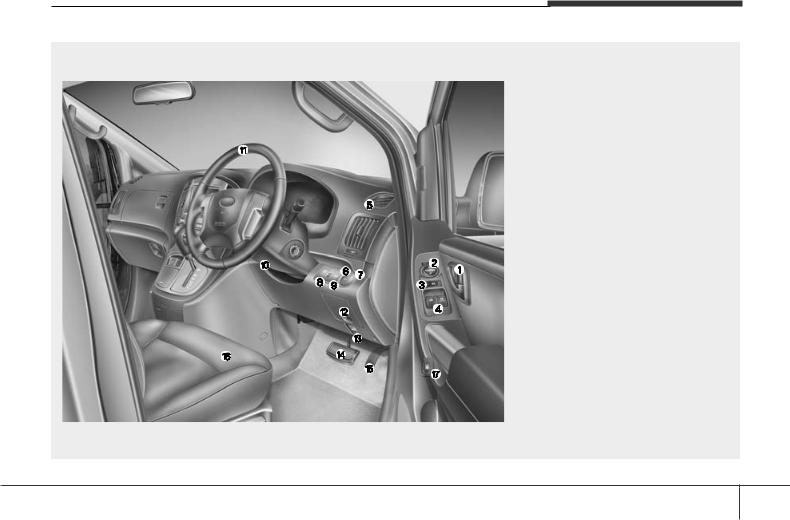
INTERIOR OVERVIEW
Left-Hand drive type
|
1. |
Door lock/unlock button* ………………. |
4-10 |
|
2. |
Outside rearview mirror control |
|
|
switch*……………………………………….. |
4-30 |
|
|
3. |
Central door lock switch* ……………… |
4-11 |
|
4. Power window switches*………………. |
4-16 |
|
|
5. |
Air vent………………………………………. |
4-63 |
|
6. |
Front fog light switch*…………………… |
4-53 |
|
7. |
Rear fog light switch* ………………….. |
4-53 |
|
8. |
Head lamp leveling device*…………… |
4-54 |
|
9. |
Instrument panel illumination control |
|
|
knob*…………………………………………. |
4-33 |
|
10. |
Steering wheel tilt control* ………….. |
4-27 |
|
11. |
Steering wheel ………………………….. |
4-26 |
|
12. Fuse box ………………………………….. |
7-55 |
|
|
13. |
Hood release lever…………………….. |
4-21 |
|
14. Brake pedal………………………………. |
5-19 |
|
|
15. |
Accelerator pedal ………………………… |
5-6 |
|
16. |
Seat…………………………………………… |
3-2 |
|
17. |
Fuel filler lid release button…………. |
4-23 |
|
* : if equipped |
OTQ027001G
B010000ATQ
2 2
Your vehicle at a glance
Right-Hand drive type
|
1. |
Door lock/unlock button* ………………. |
4-10 |
|
2. |
Outside rearview mirror control |
|
|
switch*……………………………………….. |
4-30 |
|
|
3. |
Central door lock switch* ……………… |
4-11 |
|
4. Power window switches*………………. |
4-16 |
|
|
5. |
Air vent………………………………………. |
4-63 |
|
6. |
Front fog light switch*…………………… |
4-53 |
|
7. |
Rear fog light switch* ………………….. |
4-53 |
|
8. |
Head lamp leveling device*…………… |
4-54 |
|
9. |
Instrument panel illumination control |
|
|
knob*…………………………………………. |
4-33 |
|
10. |
Steering wheel tilt control* ………….. |
4-27 |
|
11. |
Steering wheel ………………………….. |
4-26 |
|
12. Fuse box ………………………………….. |
7-55 |
|
|
13. |
Hood release lever…………………….. |
4-21 |
|
14. Brake pedal………………………………. |
5-19 |
|
|
15. |
Accelerator pedal ………………………… |
5-6 |
|
16. |
Seat…………………………………………… |
3-2 |
|
17. |
Fuel filler lid release button…………. |
4-23 |
|
* : if equipped |
OTQ027001R
B010000ATQ-EA
2 3
Your vehicle at a glance
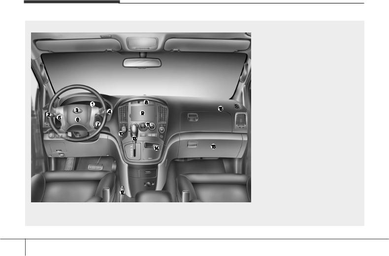
INSTRUMENT PANEL OVERVIEW
Left-Hand drive type
|
1. |
Instrument cluster……………………….. |
4-32 |
|
2. |
Light control / Turn signals …………… |
4-50 |
|
3. Horn …………………………………………. |
4-27 |
|
|
4. Wiper/Washer…………………………….. |
4-55 |
|
|
5. |
Steering wheel audio controls* …….. |
4-83 |
|
6. |
Driver’s front air bag* ………………….. |
3-44 |
|
7. |
Ignition switch………………………………. |
5-4 |
|
8. |
Digital clock* ……………………………… |
4-80 |
|
9. |
Audio*……………………………………….. |
4-82 |
|
10. Hazard warning flasher |
||
|
switch ……………………………….. |
4-50, 6-2 |
|
|
11. |
Climate control system* …………….. |
4-61 |
|
12. |
Parking brake …………………………… |
5-20 |
|
13. |
Shift lever ………………………….. |
5-12, 5-9 |
|
14. AUX, USB and iPod port* ………….. |
4-84 |
|
|
15. |
Passenger’s front air bag* ………….. |
3-44 |
|
16. Glove box ………………………………… |
4-74 |
|
|
* : if equipped |
OTQ027002G
B020000BTQ
2 4
Your vehicle at a glance
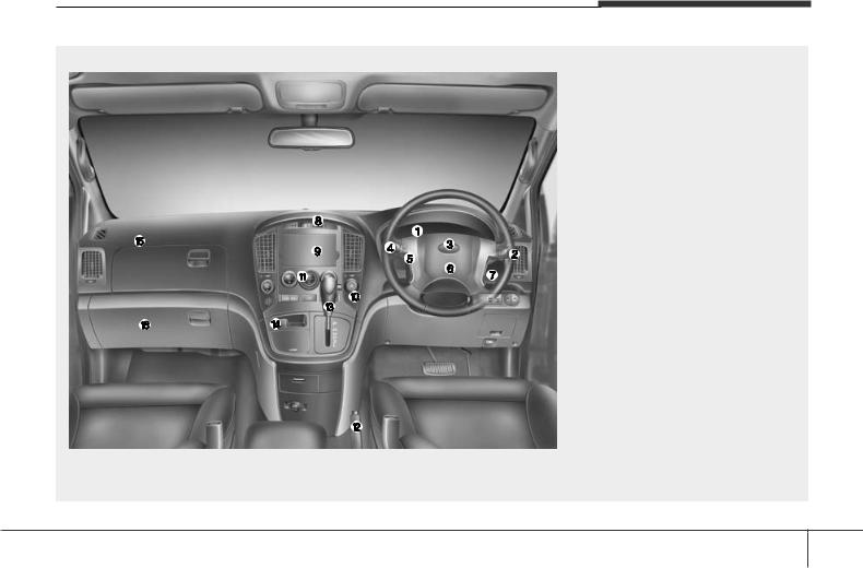
Right-Hand drive type
|
1. |
Instrument cluster……………………….. |
4-32 |
|
2. |
Light control / Turn signals …………… |
4-50 |
|
3. Horn …………………………………………. |
4-27 |
|
|
4. Wiper/Washer…………………………….. |
4-55 |
|
|
5. |
Steering wheel audio controls* …….. |
4-83 |
|
6. |
Driver’s front air bag* ………………….. |
3-44 |
|
7. |
Ignition switch………………………………. |
5-4 |
|
8. |
Digital clock* ……………………………… |
4-80 |
|
9. |
Audio*……………………………………….. |
4-82 |
|
10. Hazard warning flasher |
||
|
switch ……………………………….. |
4-50, 6-2 |
|
|
11. |
Climate control system* …………….. |
4-61 |
|
12. |
Parking brake …………………………… |
5-20 |
|
13. |
Shift lever ………………………….. |
5-12, 5-9 |
|
14. AUX, USB and iPod port* ………….. |
4-84 |
|
|
15. |
Passenger’s front air bag* ………….. |
3-44 |
|
16. Glove box ………………………………… |
4-74 |
|
|
* : if equipped |
OTQ027002R
B020000BTQ
2 5
Your vehicle at a glance
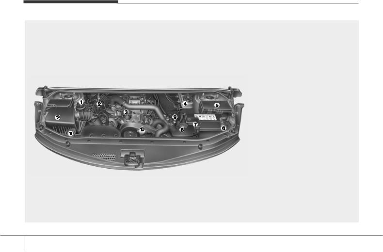
ENGINE COMPARTMENT
|
1. |
Power steering fluid reservoir ……….. |
7-30 |
|
2. |
Automatic transmission fluid |
|
|
dipstick*……………………………………… |
7-31 |
|
|
3. |
Engine oil filler cap ……………………… |
7-25 |
|
4. |
Brake fluid reservoir…………………….. |
7-29 |
|
5. Fuse box ……………………………………. |
7-56 |
|
|
6. |
Negative battery terminal……………… |
7-41 |
|
7. |
Positive battery terminal ………………. |
7-41 |
|
8. |
Engine coolant reservoir ………………. |
7-27 |
|
9. |
Engine oil dipstick ……………………….. |
7-25 |
|
10. Radiator cap …………………………….. |
7-28 |
|
|
11. Windshield washer fluid reservoir … |
7-33 |
|
|
12. Air cleaner………………………………… |
7-35 |
|
|
* : if equipped |
* The actual engine room in the vehicle may differ from the illustration.
OTQ077001
B030000ATQ
2 6

Seats / 3-2
Seat belts / 3-15
Child restraint system / 3-26
Air bag — supplemental restraint system / 3-38
Safety features of your vehicle |
3 |
|||
Safety features of your vehicle
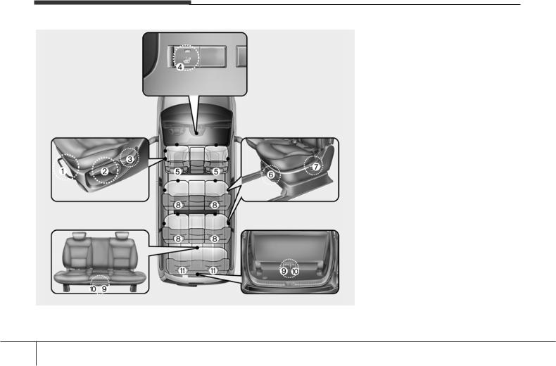
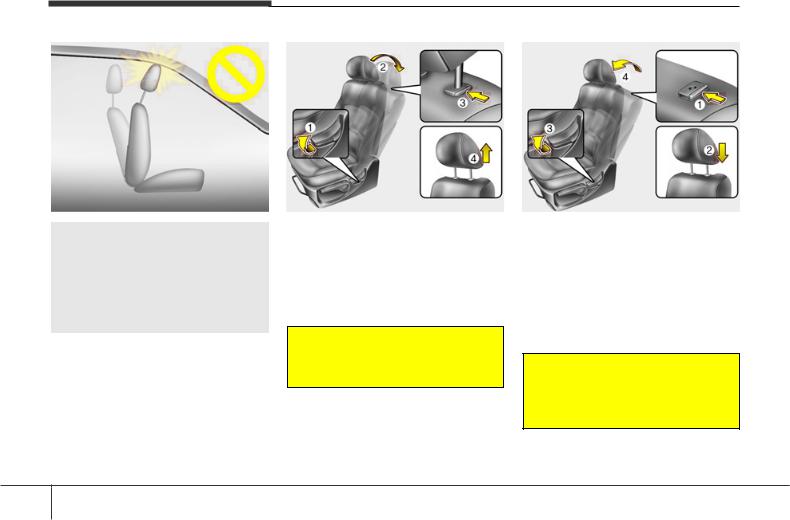
SEATS
Front seat
(1) Forward and backward
(2) Seatback angle
(3) Seat cushion height (Driver’s seat)*
(4) Seat warmer (Driver’s seat)*
(5) Headrest
2nd row seat* / 3rd row seat*
(6) Forward and backward/
Seat rotation (2nd row seat only)*
(7) Seatback angle
(8) Headrest
4th row seat*
(9) Forward and backward
(10) Seat cushion folding
(11) Headrest
*: if equipped
OTQ037001E
C010000BTQ
The actual seats in the vehicle may differ from the illustration.
3 2

 WARNING — Loose objects
Loose objects in the driver’s foot area could interfere with the operation of the foot pedals, possibly causing an accident. Do not place anything under the front seats.
 WARNING — Uprighting seat
When you return the seatback to its upright position, hold the seatback and return it slowly and be sure there are no other occupants around the seat. If the seatback is returned without being held and controlled, the back of the seat could spring forward resulting in accidental injury to a person struck by the seatback.
 WARNING — Driver responsibility for passengers
Riding in a vehicle with the seatback reclined could lead to serious or fatal injury in an accident. If a seat is reclined during an accident, the occupant’s hips may slide under the lap portion of the seat belt applying great force to the unprotected abdomen. Serious or fatal internal injuries could result. The driver must advise the front passenger to keep the seatback in an upright position whenever the vehicle is in motion.
 WARNING
Do not use a sitting cushion that reduces friction between the seat and passenger. The passenger’s hips may slide under the lap portion of the seat belt during an accident or a sudden stop. Serious or fatal internal injuries could result because the seat belt can’t operate normally.
Safety features of your vehicle
 WARNING — Driver’s seat
•Never attempt to adjust the seat while the vehicle is moving. This could result in loss of control, and an accident causing death, serious injury, or property damage.
•Do not allow anything to interfere with the normal position of the seatback. Storing items against a seatback or in any other way interfering with proper locking of a seatback could result in serious or fatal injury in a sudden stop or collision.
•Always drive and ride with your seatback upright and the lap portion of the seat belt snug and low across the hips. This is the best position to protect you in case of an accident.
•In order to avoid unnecessary and perhaps severe air bag injuries, always sit as far back as possible from the steering wheel while maintaining comfortable control of the vehicle. We recommend that your chest be at least 250 mm (10 inches) away from the steering wheel.
3 3
![]()
Safety features of your vehicle
 WARNING — Rear seatbacks
•The rear seatback must be securely latched. If not, passengers and objects could be thrown forward resulting in serious injury or death in the event of a sudden stop or collision.
•Luggage and other cargo should be laid flat in the cargo area. If objects are large, heavy, or must be piled, they must be secured. Under no circumstances should cargo be piled higher than the seatbacks. Failure to follow these warnings could result in serious injury or death in the event of a sudden stop, collision or rollover.
•No passenger should ride in the cargo area or sit or lie on folded seatbacks while the vehicle is moving. All passengers must be properly seated in seats and restrained properly while riding.
•When resetting the seatback to the upright position, make sure it is securely latched by pushing it forward and backwards.
(Continued)
(Continued)
•To avoid the possibility of burns, do not remove the carpet in the cargo area. Emission control devices beneath this floor generate high temperatures.
 WARNING
After adjusting the seat, always check that it is securely locked into place by attempting to move the seat forward or backward without using the lock release lever. Sudden or unexpected movement of the driver’s seat could cause you to lose control of the vehicle resulting in an accident.
 WARNING
•Do not adjust the seat while wearing seat belts. Moving the seat cushion forward may cause strong pressure on the abdomen.
•Use extreme caution so that hands or other objects are not caught in the seat mechanisms while the seat is moving.
•Do not put a cigarette lighter on the floor or seat. When you operate the seat, gas may gush out of the lighter and cause fire.
•If there are occupants in the rear seats, be careful while adjusting the front seat position.
•Use extreme caution when picking small objects trapped under the seats or between the seat and the center console. Your hands might be cut or injured by the sharp edges of the seat mechanism.
3 4
Safety features of your vehicle
OTQ037002
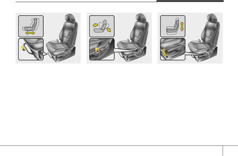
Front seat adjustment
C010101AUN
Forward and backward
To move the seat forward or backward:
1.Pull the seat slide adjustment lever under the front edge of the seat cushion up and hold it.
2.Slide the seat to the position you desire.
3.Release the lever and make sure the seat is locked in place.
Adjust the seat before driving, and make sure the seat is locked securely by trying to move forward and backward without using the lever. If the seat moves, it is not locked properly.
OTQ037003
C010102AUN
Seatback angle
To recline the seatback:
1.Lean forward slightly and lift up on the seatback recline lever located on the outside of the seat at the rear.
2.Carefully lean back on the seat and adjust the seatback of the seat to the position you desire.
3.Release the lever and make sure the seatback is locked in place. (The lever MUST return to its original position for the seatback to lock.)
OTQ037004
C010103AUN
Seat cushion height (for driver’s seat)
To change the height of the seat cushion, push the lever that is located on the outside of the seat cushion upwards or downwards.
•To lower the seat cushion, push the lever down several times.
•To raise the seat cushion, pull the lever up several times.
3 5
Safety features of your vehicle
OTQ037008E
C010107CTQ
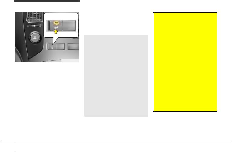
Seat warmer
(Driver’s seat, if equipped)
The seat warmer is provided to warm the driver’s seat during cold weather. With the ignition switch in the ON position, push the switch to warm the driver’s seat. During mild weather or under conditions where the operation of the seat warmer is not needed, keep the switch in the «OFF» position.
•The seat warmer defaults to the OFF position whenever the ignition switch is turned on.
NOTICE
With the seat warmer switch in ON position, the heating system in the seat turns off or on automatically depending on the seat temperature.
 CAUTION
•When cleaning the seats, do not use an organic solvent such as thinner, benzene, alcohol and gasoline. Doing so may damage the surface of the heater or seats.
•To prevent overheating the seat warmer, do not place anything on the seats that insulates against heat, such as blankets, cushions or seat covers while the seat warmer is in operation.
•Do not place heavy or sharp objects on seats equipped with seat warmer. Damage to the seat warming components could occur.
•Do not change the seat cover. It may damage the seat warmer or airventilation system.
 WARNING — Seat warmer burns
Passengers should use extreme caution when using seat warmers due to the possibility of excess heating or burns. The seat warmer may cause burns even at low temperatures, especially if used for long periods of time.
In particular, the driver must exercise extreme care for the following types of passengers:
1.Infants, children, elderly or handicapped persons, or hospital outpatients
2.Persons with sensitive skin or those that burn easily
3.Fatigued individuals
4.Intoxicated individuals
5.Individuals taking medication that can cause drowsiness or sleepiness (sleeping pills, cold tablets, etc.)
3 6
Safety features of your vehicle
OTQC031161E
C010104CTQ
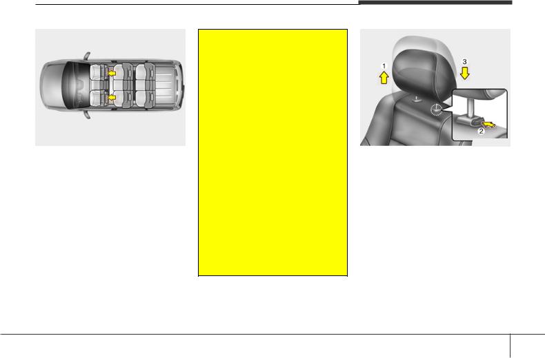
Headrest
The driver’s and front passenger’s seats are equipped with a headrest for the occupant’s safety and comfort.
The headrest not only provides comfort for the driver and front passenger, but also helps to protect the head and neck in the event of a collision.
 WARNING
•For maximum effectiveness in case of an accident, the headrest should be adjusted so the middle of the headrest is at the same height of the center of gravity of an occupant’s head. Generally, the center of gravity of most people’s head is similar with the height of the top of their eyes. Also, adjust the headrest as close to your head as possible. For this reason, the use of a cushion that holds the body away from the seatback is not recommended.
•Do not operate the vehicle with the headrests removed as severe injury to the occupants may occur in the event of an accident. Headrests may provide protection against neck injuries when properly adjusted.
•Do not adjust the headrest position of the driver’s seat while the vehicle is in motion.
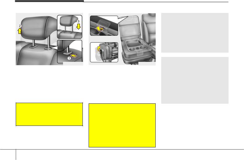
OFD037037
Adjusting the height up and down
To raise the headrest, pull it up to the desired position (1). To lower the headrest, push and hold the release button (2) on the headrest support and lower the headrest to the desired position (3).
3 7
Safety features of your vehicle
OYFH034205
 CAUTION
If you recline the seatback towards the front with the head restraint and seat cushion raised, the head restraint may come in contact with the sunvisor or other parts of the vehicle.
OTQ033200
Removal
To remove the headrest:
1.Recline the seatback (2) with the recline lever (1).
2.Raise headrest as far as it can go.
3.Press the headrest release button (3) while pulling the headrest up (4).
 WARNING
NEVER allow anyone to ride in a seat with the headrest removed.
OTQ033201
Reinstall
To reinstall the headrest :
1.Put the headrest poles (2) into the holes while pressing the release button
(1).
2.Recline the seatback (4) with the recline lever (3).
3.Adjust the headrest to the appropriate height.
 WARNING
Always make sure the headrest locks into position after reinstalling and adjusting it properly.
3 8
Safety features of your vehicle
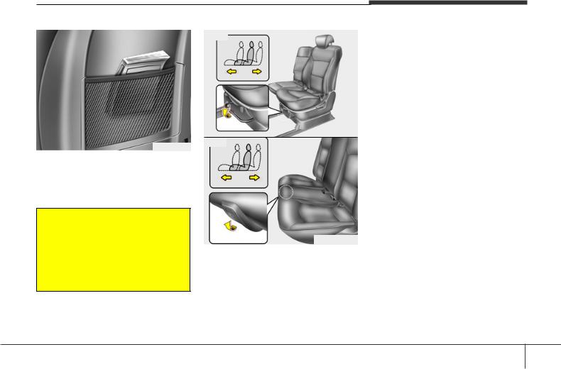
OTQ037036
C010108AUN
Seatback pocket (if equipped)
The seatback pocket is provided on the back of the front passenger’s and driver’s seatbacks.
 WARNING — Seatback pockets
Do not put heavy or sharp objects in the seatback pockets. In an accident they could come loose from the pocket and injure vehicle occupants.
Type A
OTQ037011
Type B
OTQ037011G
Rear seat adjustment
C010301ATQ
Forward and backward (2nd and 3rd row, if equipped)
To move the seat forward or backward:
1.Pull up the seat slide adjustment lever under the front edge of the seat cushion and hold it.
2.Slide the seat to the position you desire.
3.Release the lever and make sure the seat is locked in place.
Adjust the seat before driving, and make sure the seat is locked securely by trying to move forward and backward without using the lever. If the seat moves, it is not locked properly.
3 9
Safety features of your vehicle
Type A
OTQ037012
Type B
OTQ037012G
Type C
OTQ037015
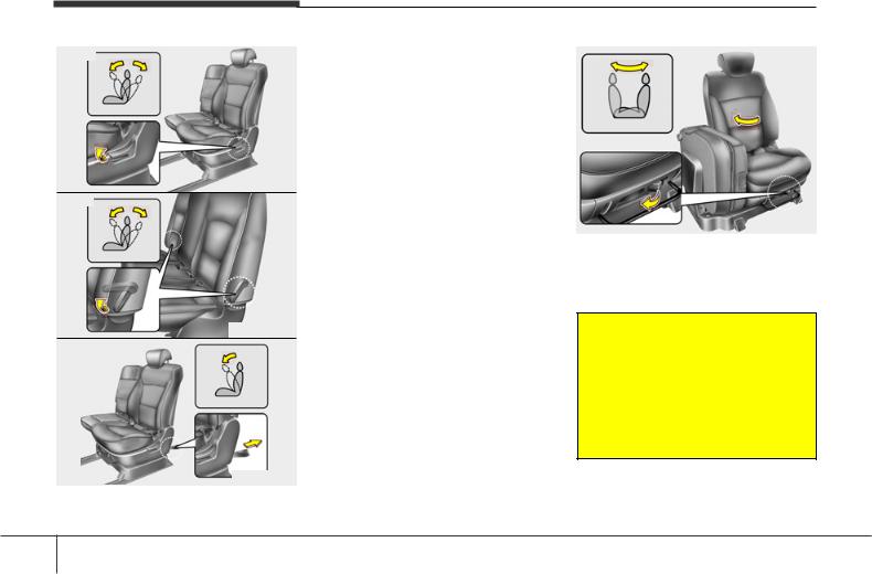
C010302ATQ
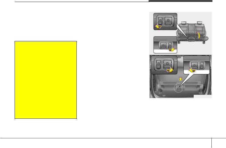
Seatback angle (if equipped)
To recline the seatback:
1.Pull or pull up the seatback recline lever.
2.Carefully lean back the seat and adjust the seatback to the position you desire.
3.Release the lever and make sure the seatback is locked in place. (The lever MUST return to its original position for the seatback to lock.)
OTQ037033
Seat rotation
(2nd row seat, if equipped)
Pull the lever and rotate the seat clockwise.
 WARNING
• Never rotate the seat while the vehicle is in motion.
• When the seat is rotated, be sure that the seat is securely locked in position. It not, it may result in serious injury in the event of a sudden stop.
3 10
Safety features of your vehicle
OTQC031161F
C010303CTQ
Headrest
The rear seats are equipped with headrests in the outboard seating positions (except center seating position) for the occupant’s safety and comfort.
The headrest not only provides comfort for passengers, but also helps to protect the head and neck in the event of a collision.
 WARNING
•For maximum effectiveness in case of an accident, the headrest should be adjusted so the middle of the headrest is at the same height of the center of gravity of an occupant’s head. Generally, the center of gravity of most people’s head is similar with the height of the top of their eyes. Also, adjust the headrest as close to your head as possible. The use of a cushion that holds the body away from the seatback is not recommended.
•Do not operate the vehicle with the headrests removed as severe injury to an occupant may occur in the event of an accident. Headrests may provide protection against severe neck injuries when properly adjusted.
 CAUTION
When there is no occupant in the rear seats, adjust the height of the headrest to the lowest position. The rear seat headrest can reduce the visibility of the rear area.
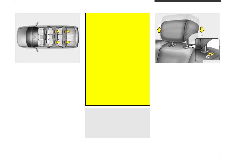
OHM038017
Adjusting the height up and down
To raise the headrest, pull it up to the desired position (1). To lower the headrest, push and hold the release button (2) on the headrest support and lower the headrest to the desired position (3).
3 11
Safety features of your vehicle
OHM038018N
Removal
To remove the headrest, raise it as far as it can go then press the release button
(1) while pulling upward (2).
To reinstall the headrest, put the headrest poles (3) into the holes while pressing the release button (1). Then adjust it to the appropriate height.
 WARNING
Make sure the headrest locks in position after adjusting it to properly protect the occupants.
OTQ037031
C010304ATQ
Center seat folding (if equipped)
1.Stow the rear seat belt in the pocket to prevent the seat belt from being damaged.
2.Pull the release knob and fold the seatback forward.
3.Fold up the seat.
 WARNING — Uprighting seat
When you return the seatback to its upright position, hold the seatback and return it slowly. If the seatback is returned without holding it, the back of the seat could spring forward resulting in injury caused by being struck by the seatback.
CAUTION — Damaging rear seat belt buckles
When you fold the rear (2nd and/or 3rd row) seatback, insert the buckle in the pocket between the rear seatback and cushion. Doing so can prevent the buckle from being damaged by the rear seatback.
CAUTION — Rear seat belts
When returning the rear (2nd and/or 3rd row) seatbacks to the upright position, remember to return the rear shoulder belts to their proper position. Routing the seat belt webbing through the rear seat belt guides will help keep the belts from being trapped behind or under the seats.
3 12
Safety features of your vehicle
C010307ATQ
Folding the rear seat
(4th row seat, if equipped)
The rear seat cushion may be folded to facilitate carrying long items or to increase the luggage capacity of the vehicle.
 WARNING
The purpose of the fold rear seat is to allow you to carry longer objects that could not be accommodated in the cargo area.
Never allow passengers to sit on a improper position (ex : top of the folded seat, floor etc.) while the car is moving as this is not a proper seating position and no seat belts are available for use. This could result in serious injury or death in case of an accident or sudden stop. Objects carried on the cargo area should not extend higher than the top of the front seatbacks. Doing this could allow cargo to slide forward and cause injury or damage during sudden stops.
To fold the rear seat:
1.Stow the rear seat belt in the pocket to prevent the seat belt from being damaged.
2.Set the 3rd row seatback to the upright position and if necessary, slide the 3rd row seat forward.
OTQ037016
OTQ037017
3. Pull on the seatcushion folding lever, then fold the seat toward the rear of the vehicle.
4. Increase the luggauge compartment space by moving the rear seat using the sliding lever.
3 13
![]()
Safety features of your vehicle
 WARNING
When you return the rear seat cushion to its locking position after being folded:
Be careful not to damage the seat belt webbing or buckle. Do not allow the seat belt webbing or buckle to get caught or pinched in the rear seat. Ensure that the seat is completely locked into its proper position by pushing the seat cushion and seatback.
Otherwise, in an accident or sudden stop, the seat could fold, which could result in serious injury or death.
OUN026140
 WARNING
The headrest on the seat (especially the last row seat) should be adjusted so the middle of the headrest is at the same height as the top of the occupant’s eyes.
If the tailgate is pushed down to close when a passenger’s head is not against a properly adjusted headrest or a tall person is seated, the tailgate may hit the occupant’s head, which could cause injury.
 WARNING — Cargo
Cargo should always be secured to prevent it from being thrown about the vehicle in a collision and causing injury to the vehicle occupants. Do not place objects in the rear seats, since they cannot be properly secured and may hit the front seat occupants in a collision.
 WARNING — Cargo loading
Make sure the engine is off, the automatic transmission is in P (Park) or the manual transmission is in R (Reverse) or 1st, and the parking brake is securely applied whenever loading or unloading cargo. Failure to take these steps may allow the vehicle to move if the shift lever is inadvertently moved to another position.
3 14

SEAT BELTS
C020100CUN
Seat belt restraint system
 WARNING
•For maximum restraint system protection, the seat belts must always be used whenever the car is moving.
•Seat belts are most effective when seatbacks are in the upright position.
•Children age 12 and under must always be properly restrained in the rear seat. Never allow children to ride in the front passenger seat. If a child over 12 must be seated in the front seat, he/she must be properly belted and the seat should be moved as far back as possible.
•Never wear the shoulder belt under your arm or behind your back. An improperly positioned shoulder belt can cause serious injuries in a crash. The shoulder belt should be positioned midway over your shoulder across your collarbone.
(Continued)
(Continued)
•Never wear a seat belt over fragile objects. If there is a sudden stop or impact, the seat belt can damage it.
•Avoid wearing twisted seat belts. A twisted belt can’t do its job as well. In a collision, it could even cut into you. Be sure the belt webbing is straight and not twisted.
•Be careful not to damage the belt webbing or hardware. If the belt webbing or hardware is damaged, replace it.
Safety features of your vehicle
 WARNING
Seat belts are designed to bear upon the bony structure of the body, and should be worn low across the front of the pelvis, or the pelvis, chest and shoulders, as applicable; wearing the lap section of the belt across the abdominal area must be avoided.
Seat belts should be adjusted as firmly as possible, consistent with comfort, to provide the protection for which they have been designed. A slack belt will greatly reduce the protection afforded to the occupant.
Care should be taken to avoid contamination of the webbing with polishes, oils and chemicals and particularly battery acid. Cleaning may safely be carried out using mild soap and water. The belt should be replaced if webbing becomes frayed, contaminated or damaged.
(Continued)
3 15

Safety features of your vehicle
(Continued)
It is essential to replace the entire assembly after it has been worn in a severe impact even if damage to the assembly is not obvious. Belts should not be worn with straps twisted. Each seat belt assembly must only be used by one occupant; it is dangerous to put a belt around a child being carried on the occupant’s lap.
 WARNING
•No modifications or additions should be made by the user which will either prevent the seat belt adjusting devices from operating to remove slack, or prevent the seat belt assembly from being adjusted to remove slack.
•When you fasten the seat belt, be careful not to latch the seat belt in buckles of other seat. It’s very dangerous and you may not be protected by the seat belt properly.
•Do not unfasten the seat belt and do not fasten and unfasten the seat belt repeatedly while driving. This could result in loss of control, and an accident causing death, serious injury, or property damage.
•When fastening the seat belt, make sure that the seat belt does not pass over objects that are hard or can break easily.
•Make sure there is nothing in the buckle. The seat belt may not be fastened securely.
1GQA2083
D150302AEN-EE
Seat belt warning (if equipped)
As a reminder to the driver, the seat belt warning light will blink for approximately 6 seconds each time you turn the ignition switch ON regardless of belt fastening.
If the driver’s seat belt is unfastened after the ignition switch is ON, the seat belt warning light blinks again for approximately 6 seconds.
Seat belt warning chime (if equipped)
If the driver’s seat belt is not fastened when the ignition switch is turned ON or if it is unfastened after the ignition switch is ON, the seat belt warning chime will sound for approximately 6 seconds. At this time, if the seat belt is fastened, the chime will stop at once.
3 16

Safety features of your vehicle
NOTICE
If you are not able to pull out the seat belt from the retractor, firmly pull the belt out and release it. Then you will be able to pull the belt out smoothly.
B180A01NF-1
C020102AEN
Lap/shoulder belt
To fasten your seat belt:
To fasten your seat belt, pull it out of the retractor and insert the metal tab (1) into the buckle (2). There will be an audible «click» when the tab locks into the buckle. The seat belt automatically adjusts to the proper length only after the lap belt portion is adjusted manually so that it fits snugly around your hips. If you lean forward in a slow, easy motion, the belt will extend and let you move around. If there is a sudden stop or impact, however, the belt will lock into position. It will also lock if you try to lean forward too quickly.
B200A02NF
 WARNING
You should place the lap belt portion as low as possible and snugly across your hips, not on your waist. If the lap belt is located too high on your waist, it may increase the chance of injury in the event of a collision. Both arms should not be under or over the belt. Rather, one should be over and the other under, as shown in the illustration.
Never wear the seat belt under the arm nearest the door.
3 17

Safety features of your vehicle
Front seat
OEN036029
Height adjustment (if equipped)
You can adjust the height of the shoulder belt anchor to one of 5 positions for maximum comfort and safety.
The height of the adjusting seat belt should not be too near your neck. The shoulder portion should be adjusted so that it lies across your chest and midway over your shoulder nearest the door and not your neck.
To adjust the height of the seat belt anchor, lower or raise the height adjuster into an appropriate position.
To raise the height adjuster, pull it up (1). To lower it, push it down (3) while pressing the height adjuster button (2).
Release the button to lock the anchor into position. Try sliding the height adjuster to make sure that it has locked into position.
 WARNING
•Verify the shoulder belt anchor is locked into position at the appropriate height. Never position the shoulder belt across your neck or face. Improperly positioned seat belts can cause serious injuries in an accident.
•Failure to replace seat belts after an accident could leave you with damaged seat belts that will not provide protection in the event of another collision leading to personal injury or death. Replace your seat belts after being in an accident as soon as possible.
B210A01NF-1
To release the seat belt:
The seat belt is released by pressing the release button (1) in the locking buckle. When it is released, the belt should automatically draw back into the retractor.
If this does not happen, check the belt to be sure it is not twisted, then try again.
3 18

Safety features of your vehicle
B220A04NF-1
C020103AUN
Lap belt (if equipped)
To fasten your seat belt:
To fasten a 2-point static type belt, insert the metal tab (1) into the locking buckle
(2). There will be an audible «click» when the tab locks into the buckle. Check to make sure the belt is properly locked and that the belt is not twisted.
OHM039105N
Too high
B220B01NF
With a 2-point static type seat belt, the length must be adjusted manually so it fits snugly around your body. Fasten the belt and pull on the loose end to tighten. The belt should be placed as low as possible on your hips, not on your waist. If the belt is too high, it could increase the possibility of your being injured in an accident.
OTQ037020
When using the rear center seat belt, the buckle with the “CENTER” mark must be used.
3 19

Safety features of your vehicle
Type A
Type B
B210A02NF-1
To release the seat belt:
When you want to release the seat belt, press the button (1) in the locking buckle.
 WARNING
The center lap belt latching mecha-
nism is different from those for the Type C rear seat shoulder belts. When fas-
tening the rear seat shoulder belts or the center lap belt, make sure they are inserted into the correct buckles to obtain maximum protection from the seat belt system and assure proper operation.
C020105AUN
Stowing the rear seat belt
•The rear seat belt buckles can be stowed in the pocket between the rear seatback and cushion when not in use.
•The center seat belt can be stowed with the plate and webbing rolled in the pocket between the rear seatback and cushion.
OTQ037021
OTQ037022
OTQ037022G
3 20

Safety features of your vehicle
OED030300
C020200CEN
Pre-tensioner seat belt (if equipped)
Your vehicle is equipped with driver’s and front passenger’s pre-tensioner seat belts. The purpose of the pre-tensioner is to make sure that the seat belts fit tightly against the occupant’s body in certain frontal collisions. The pre-tensioner seat belts may be activated in crashes where the frontal collision is severe enough.
When the vehicle stops suddenly, or if the occupant tries to lean forward too quickly, the seat belt retractor will lock into position. In certain frontal collisions, the pre-tensioner will activate and pull the seat belt into tighter contact against the occupant’s body.
 WARNING
For your safety, be sure that the belt webbing is not loose or twisted and always sit properly on your seat.
1KMB3311A
The seat belt pre-tensioner system consists mainly of the following components. Their locations are shown in the illustration:
1.SRS air bag warning light
2.Retractor pre-tensioner assembly
3.SRS control module
3 21

Safety features of your vehicle
 WARNING
To obtain maximum benefit from a pre-tensioner seat belt:
1.The seat belt must be worn correctly and adjusted to the proper position. Please read and follow all of the important information and precautions about your vehicle’s occupant safety features – including seat belts and air bags – that are provided in this manual.
2.Be sure you and your passengers always wear seat belts properly.
NOTICE
•Both the driver’s and front passenger’s pre-tensioner seat belts may be activated in certain frontal collisions.
•When the pre-tensioner seat belts are activated, a loud noise may be heard and fine dust, which may appear to be smoke, may be visible in the passenger compartment. These are normal operating conditions and are not hazardous.
•Although it is harmless, the fine dust may cause skin irritation and should not be breathed for prolonged periods. Wash all exposed skin areas thoroughly after an accident in which the pretensioner seat belts were activated.
NOTICE
Because the sensor that activates the SRS air bag is connected with the pretensioner seat belt, the SRS air bag warning light 
 on the instrument panel will illuminate for approximately 6 seconds after the ignition switch has been turned to the ON position, and then it should turn off.
 CAUTION
If the pre-tensioner seat belt is not working properly, this warning light will illuminate even if there is no malfunction of the SRS air bag.
If the SRS air bag warning light does not illuminate when the ignition switch is turned to ON, or if it remains illuminated after illuminating for approximately 6 seconds, or if it illuminates while the vehicle is being driven, we recommend that the system be inspected by an authorized HYUNDAI dealer.
 WARNING
•Pre-tensioners are designed to operate only one time. After activation, pre-tensioner seat belts must be replaced. All seat belts, of any type, should always be replaced after they have been worn during a collision.
•The pre-tensioner seat belt assembly mechanisms become hot during activation. Do not touch the pre-tensioner seat belt assemblies for several minutes after they have been activated.
•Do not attempt to inspect or replace the pre-tensioner seat belts yourself. We recommend that the system be inspected by an authorized HYUNDAI dealer.
•Do not strike the pre-tensioner seat belt assemblies.
•Do not attempt to service or repair the pre-tensioner seat belt system in any manner.
(Continued)
3 22

(Continued)
•Improper handling of the pre-ten- sioner seat belt assemblies, and failure to heed the warnings not to strike, modify, inspect, replace, service or repair the pre-tension- er seat belt assemblies may lead to improper operation or inadvertent activation and serious injury.
•Always wear the seat belts when driving or riding in a motor vehicle.
•If the vehicle or pre-tensioner seat belt must be discarded, we recommend that you contact an authorized HYUNDAI dealer.
 CAUTION
Body work on the front area of the vehicle may damage the pre-ten- sioner seat belt system. Therefore, we recommend that the system be serviced by an authorized HYUNDAI dealer.
C020300AUN
Seat belt precautions
 WARNING
All occupants of the vehicle must wear their seat belts at all times. Seat belts and child restraints reduce the risk of serious or fatal injuries for all occupants in the event of a collision or sudden stop. Without a seat belt, occupants could be shifted too close to a deploying air bag, strike the interior structure or be thrown from the vehicle. Properly worn seat belts greatly reduce these hazards.
Always follow the precautions about seat belts, air bags and occupant seating contained in this manual.
Safety features of your vehicle
C020306AUN
Infant or small child
You should be aware of the specific requirements in your country. Child and/or infant seats must be properly placed and installed in the rear seat. For more information about the use of these restraints, refer to “Child restraint system” in this section.
 WARNING
Every person in your vehicle needs to be properly restrained at all times, including infants and children. Never hold a child in your arms or lap when riding in a vehicle. The violent forces created during a crash will tear the child from your arms and throw the child against the interior. Always use a child restraint appropriate for your child’s height and weight.
3 23
![]()
Safety features of your vehicle
NOTICE
Small children are best protected from injury in an accident when properly restrained in the rear seat by a child restraint system that meets the requirements of the Safety Standards of your country. Before buying any child restraint system, make sure that it has a label certifying that it meets Safety Standards of your country. The restraint must be appropriate for your child’s height and weight. Check the label on the child restraint for this information. Refer to “Child restraint system” in this section.
C020301AUN
Larger children
Children who are too large for child restraint systems should always occupy the rear seat and use the available lap/shoulder belts. The lap portion should be fastened snug on the hips and as low as possible. Check belt fit periodically. A child’s squirming could put the belt out of position. Children are afforded the most safety in the event of an accident when they are restrained by a proper restraint system in the rear seat.
If a larger child (over age 12) must be seated in the front seat, the child should be securely restrained by the available lap/shoulder belt and the seat should be placed in the rearmost position.
Children age 12 and under should be restrained securely in the rear seat. NEVER place a child age 12 and under in the front seat. NEVER place a rear facing child seat in the front seat of a vehicle.
If the shoulder belt portion slightly touches the child’s neck or face, try placing the child closer to the center of the vehicle. If the shoulder belt still touches their face or neck they need to be returned to a child restraint system.
 WARNING — Shoulder belts on small children
•Never allow a shoulder belt to be in contact with a child’s neck or face while the vehicle is in motion.
•If seat belts are not properly worn and adjusted on children, there is a risk of death or serious injury.
C020302AUN
Pregnant women
The use of a seat belt is recommended for pregnant women to lessen the chance of injury in an accident. When a seat belt is used, the lap belt portion should be placed as low and snugly as possible on the hips, not across the abdomen. For specific recommendations, consult a physician.
C020303AUN
Injured person
A seat belt should be used when an injured person is being transported. When this is necessary, you should consult a physician for recommendations.
C020304AUN
One person per belt
Two people (including children) should never attempt to use a single seat belt. This could increase the severity of injuries in case of an accident.
3 24

Safety features of your vehicle
C020305AUN
Do not lie down
To reduce the chance of injuries in the event of an accident and to achieve maximum effectiveness of the restraint system, all passengers should be sitting up and the front and rear seats should be in an upright position when the car is moving. A seat belt cannot provide proper protection if the person is lying down in the rear seat or if the front and rear seats are in a reclined position.
 WARNING
Riding with a reclined seatback increases your chance of serious or fatal injuries in the event of a collision or sudden stop. The protection of your restraint system (seat belts and air bags) is greatly reduced by reclining your seat. Seat belts must be snug against your hips and chest to work properly. The more the seatback is reclined, the greater the chance that an occupant’s hips will slide under the lap belt causing serious internal injuries or the occupant’s neck could strike the shoulder belt. Drivers and passengers should always sit well back in their seats, properly belted, and with the seatbacks upright.
C020400AEN
Care of seat belts
Seat belt systems should never be disassembled or modified. In addition, care should be taken to assure that seat belts and belt hardware are not damaged by seat hinges, doors or other abuse.
 WARNING
When you return the rear seat to its seating position after the rear seat has been folded, be careful not to damage the seat belt webbing or buckle. Be sure that the webbing or buckle does not get caught or pinched in the rear seat. A seat belt with damaged webbing or buckle could possibly fail during a collision or sudden stop, resulting in serious injury. If the webbing or buckles are damaged, get them replaced immediately.
C020401AEN
Periodic inspection
All seat belts should be inspected periodically for wear or damage of any kind. Any damaged parts should be replaced as soon as possible.
C020402AUN
Keep belts clean and dry
Seat belts should be kept clean and dry. If belts become dirty, they can be cleaned by using a mild soap solution and warm water. Bleach, dye, strong detergents or abrasives should not be used because they may damage and weaken the fabric.
C020403AEN
When to replace seat belts
Entire in-use seat belt assembly or assemblies should be replaced if the vehicle has been involved in an accident. This should be done even if no damage is visible. If you have additional questions regarding seat belt operation, we recommend that you consult an authorized HYUNDAI dealer.
3 25

Safety features of your vehicle
CHILD RESTRAINT SYSTEM
C030000AEN
Children riding in the car should sit in the rear seat and must always be properly restrained to minimize the risk of injury in an accident, sudden stop or sudden maneuver. According to accident statistics, children are safer when properly restrained in the rear seats than in the front seat. Larger children not in a child restraint should use one of the seat belts provided.
You should be aware of the specific requirements in your country. Child and/or infant safety seats must be properly placed and installed in the rear seat. You must use a commercially available child restraint system that meets the requirements of the Safety Standards of your country. Child restraint systems are designed to be secured in vehicle seats by lap belts or the lap belt portion of a lap/shoulder belt, or by a tether anchor and/or ISOFIX anchors (if equipped).
Children could be injured or killed in a crash if their restraints are not properly secured. For small children and babies, a child seat or infant seat must be used. Before buying a particular child restraint system, make sure it fits your car seat and seat belts, and fits your child.
Follow all the instructions provided by the manufacturer when installing the child restraint system.
 WARNING
•A child restraint system must be placed in the rear seat. Never install a child or infant seat on the front passenger’s seat. Should an accident occur and cause the passenger-side air bag to deploy, it could severely injure or kill an infant or child seated in an infant or child seat. Thus only use a child restraint in the rear seat of your vehicle.
•A seat belt or child restraint system can become very hot if it is left in a closed vehicle on a sunny day, even if the outside temperature does not feel hot. Be sure to check the seat cover and buckles before placing a child there.
(Continued)
(Continued)
•When the child restraint system is not in use, store it in the luggage area or fasten it with a seat belt so that it will not be thrown forward in the case of a sudden stop or an accident.
•Children may be seriously injured or killed by an inflating air bag. All children, even those too large for child restraints, must ride in the rear seat.
3 26

 WARNING
To reduce the chance of serious or fatal injuries:
•Children of all ages are safer when restrained in the rear seat. A child riding in the front passenger seat can be forcefully struck by an inflating air bag resulting in serious or fatal injuries.
•Always follow the child restraint system manufacturer’s instructions for installation and use of the child restraint.
•Always make sure the child seat is secured properly in the car and your child is securely restrained in the child seat.
•Never hold a child in your arms or lap when riding in a vehicle. The violent forces created during a crash will tear the child from your arms and throw the child against the car’s interior.
•Never put a seat belt over yourself and a child. During a crash, the belt could press deep into the child causing serious internal injuries.
(Continued)
(Continued)
•Never leave children unattended in a vehicle – not even for a short time. The car can heat up very quickly, resulting in serious injuries to children inside. Even very young children may inadvertently cause the vehicle to move, entangle themselves in the windows, or lock themselves or others inside the vehicle.
•Never allow two children, or any two persons, to use the same seat belt.
•Children often squirm and reposition themselves improperly. Never let a child ride with the shoulder belt under their arm or behind their back. Always properly position and secure children in the rear seat.
•Never allow a child to stand-up or kneel on the seat or floor of a moving vehicle. During a collision or sudden stop, the child can be violently thrown against the vehicle’s interior, resulting in serious injury.
(Continued)
Safety features of your vehicle
(Continued)
•Never use an infant carrier or a child safety seat that «hooks» over a seatback, it may not provide adequate security in an accident.
•Seat belts can become very hot, especially when the car is parked in direct sunlight. Always check seat belt buckles before fastening them over a child.
•After an accident, we recommend that the system be checked by an authorized HYUNDAI dealer.
3 27

Safety features of your vehicle
Rearward-facing child restraint system
CRS09
Forward-facing child restraint system
OTQ037038
C030100AEN
Using a child restraint system
For small children and babies, the use of a child seat or infant seat is required. This child seat or infant seat should be of appropriate size for the child and should be installed in accordance with the manufacturer’s instructions.
For safety reasons, we recommend that the child restraint system be used in the rear seats.
 WARNING
Never place a rear-facing child restraint in the front passenger seat, because of the danger that an inflating passenger-side air bag could impact the rear-facing child restraint and kill the child.
 WARNING — Child seat installation
•A child can be seriously injured or killed in a collision if the child restraint is not properly anchored to the car and the child is not properly restrained in the child restraint. Before installing the child restraint system, read the instructions supplied by the child restraint system manufacturer.
•If the seat belt does not operate as described in this section, we recommend that the system be checked by an authorized HYUNDAI dealer.
•Failure to observe this manual’s instructions regarding child restraint systems and the instructions provided with the child restraint system could increase the chance and/or severity of injury in an accident.
•If the vehicle headrest prevents proper installation of a child seat (as described in the child seat system manual, the headrest of the respective seating position shall be readjusted or entirely removed.
3 28

Safety features of your vehicle
2. Extend the latch plate tongue of the lap belt.
3. Route the lap belt through the restraint according to the seat manufacturer’s instructions.
4. Buckle the seat belt and adjust the lap belt for a snug hold on the child restraint by pulling on the loose end of the belt. After installation of the child restraint system, try to move it in all directions to be sure the child restraint
1GHA2260 system is securely installed.
OTQ007002
C030101ATQ
Installing a child restraint system by lap belt
To install a child restraint system on the outboard or center rear seats, do the following:
1.Place the child restraint system on the rear seat.
E2MS103005
C030102AUN
Installing a child restraint system by lap/shoulder belt (if equipped)
To install a child restraint system on the outboard or center rear seats, do the following:
1.Place the child restraint system in the seat and route the lap/shoulder belt around or through the restraint, following the restraint manufacturer’s instructions. Be sure the seat belt webbing is not twisted.
3 29

Safety features of your vehicle
OEN036101
2.Fasten the lap/shoulder belt latch into the buckle. Listen for the distinct “click” sound.
Position the release button so that it is easy to access in case of an emergency.
OEN036104
3.Buckle the seat belt and allow the seat belt to take up any slack. After installation of the child restraint system, try to move it in all directions to be sure the child restraint system is securely installed.
If you need to tighten the belt, pull more webbing toward the retractor. When you unbuckle the seat belt and allow it to retract, the retractor will automatically revert back to its normal seated passenger emergency locking usage condition.
1GHA2260
C030101AUN
Installing a child restraint system by lap belt (on the center rear seat) (if equipped) — Except Europe
To install a child restraint system on the center rear seats, do the following:
1.Place the child restraint system on the center rear seat.
2.Extend the latch plate tongue of the lap belt.
3.Route the lap belt through the restraint according to the seat manufacturer’s instructions.
4.Buckle the seat belt and adjust the lap belt for a snug hold on the child restraint by pulling on the loose end of the belt. After installation of the child restraint system, try to move it in all directions to be sure the child restraint system is securely installed.
3 30

Safety features of your vehicle
C030105ATQ
Child seat restraint suitability for seat position using the seat belt — For Europe
Use child safety seats that have been officially approved and are appropriate for your children. When using the child safety seats, refer to the following table.
8-seater Wagon
|
Seating position |
|||||||
|
Age group |
|||||||
|
Front |
2nd |
2nd |
3rd |
3rd |
|||
|
passenger |
outboard |
center |
outboard |
center |
|||
|
0 : Up to 10 kg |
X |
X |
X |
U |
U |
||
|
(0 — 9 months) |
|||||||
|
0+ : Up to 13 kg |
L4 |
L4 |
L4 |
U |
U |
||
|
(0 — 2 years) |
|||||||
|
I : 9 kg to 18 kg |
L1, L2, L3 |
L1, L2, L3 |
L1, L2, L3 |
U |
U |
||
|
(9 months — 4 years) |
|||||||
|
II & III : 15 kg to 36 kg |
X |
X |
X |
U |
U |
||
|
(4 — 12 years) |
|||||||
5/6-seater Van
|
Seating position |
|||||
|
Age group |
|||||
|
Front |
Front |
2nd |
2nd |
||
|
passenger |
center |
outboard |
center |
||
|
0 : Up to 10 kg |
X |
X |
X |
X |
|
|
(0 — 9 months) |
|||||
|
0+ : Up to 13 kg |
L4 |
X |
L4 |
X |
|
|
(0 — 2 years) |
|||||
|
I : 9 kg to 18 kg |
L1, L2, L3 |
X |
L1, L2, L3 |
X |
|
|
(9 months — 4 years) |
|||||
|
II & III : 15 kg to 36 kg |
X |
X |
X |
X |
|
|
(4 — 12 years) |
|||||
L1 : Suitable for Romer Lord Plus (E1
03301136) approved for the use in this mass group
L2 : Suitable for Romer DUO (E1
3301133) approved for the use in this mass group
L3 : Suitable for BeSafe iZi COMFORT
(E4 03443206) approved for the use in this mass group
L4 : Suitable for Bebe comfort ELIOS
(E2 037014) approved for the use in this mass group
U : Suitable for «universal» category restraints approved for use in this mass group
UF : Suitable for forward-facing «universal» category restraints approved for the use in this mass group
X : Seat position not suitable for children in this mass group
3 31

Safety features of your vehicle
OTQ037039L
C030103ATQ
Securing a child restraint seat with “Tether Anchor” system
(if equipped)
Child restraint hook holders are located behind the rear seats.
2GHA3300L
1.Route the child restraint seat strap over the seatback.
For vehicles with adjustable headrest, route the tether strap under the headrest and between the headrest posts, otherwise route the tether strap over the top of the seatback.
2.Connect the tether strap hook to the appropriate child restraint hook holder and tighten to secure the seat.
 WARNING
A child can be seriously injured or killed in a collision if the child restraint is not properly anchored to the car and the child is not properly restrained in the child restraint. Always follow the child seat manufacturer’s instructions for installation and use.
 WARNING — Tether strap
Never mount more than one child restraint to a single tether or to a single lower anchorage point. The increased load caused by multiple seats may cause the tethers or anchorage points to break, causing serious injury or death.
3 32

Safety features of your vehicle
 WARNING — Child restraint check
Check that the child restraint system is secure by pushing and pulling it in different directions. Incorrectly fitted child restraints may swing, twist, tip or separate causing death or serious injury.
 WARNING
—Child restraint anchorage
•Child restraint anchorages are designed to withstand only those loads imposed by correctly fitted child restraints. Under no circumstances are they to be used for adult seat belts or harnesses or for attaching other items or equipment to the vehicle.
•The tether strap may not work properly if attached somewhere other than the correct tether anchor.
OTQ038161E
C030104BTQ
Securing a child restraint system with “ISOFIX” system and “Tether Anchorage” system (if equipped)
ISOFIX is a standardised method of fitting child seats that eliminates the need to use the standard adult seat belt to secure the seat in the vehicle. This enables a much more secure and positive location with the added benefit of easier and quicker installation.
An ISOFIX-seat can only be installed if it has vehicle-specific approval in accordance with the requirements of ECER44.
OTQ037040L
There are ISOFIX marks located on the lower portion of each side of the rear seatbacks. These marks indicate the position of the lower anchors for child restraints so equipped.
3 33
 Loading…
- Manuals
- Brands
- Hyundai Manuals
- Automobile
- Starex H-1 2004
- Owner’s manual
-
Contents
-
Table of Contents
-
Bookmarks
Quick Links
Chapters
-
Table of Contents
9 -
Before Driving Your Vehicle
15 -
Instruments and Controls
66 -
Starting and Operating
141 -
In Case of Emergency
173 -
Vehicle Maintenance Requirements
220 -
Do-It Yourself Maintenance
238
Related Manuals for Hyundai Starex H-1 2004
Summary of Contents for Hyundai Starex H-1 2004
-
Page 2
A000A01A-GAT This Owner’s Manual should be considered a part of the car and remain with it when it is sold for the use of the next owner. OWNER’S I.D. ORIGINAL: NAME: ADDRESS: STREET: TOWN: COUNTRY: P.CODE: DATE OF SALE: SUBSEQUENT: NAME: ADDRESS: STREET:… -
Page 3
Specifications HSRFL280 All information in the Owner’s Manual is current at the time of publication. Hyundai reserves the right to make changes at any time as part of our policy of continual product improvement may be carried out. This manual applies to current Hyundai H-1 models and explanations of optional as well as standard equipment… -
Page 4
A020A01P-AAT RESPONSIBILITY FOR MAINTENANCE The maintenance requirements for your new Hyundai are found in Section 6. As the owner, it is your responsibility to see that all maintenance operations specified by the manufacturer are carried out at the appropriate intervals. When the vehicle is used in severe driving conditions, more frequent maintenance is required for some operations. -
Page 5
Hyundai we build is something of which we’re very proud. Your Owner’s Manual will introduce you to the features and operation of your new Hyundai. It is suggested that you read it carefully because the information it contains can contribute greatly to the satisfaction you receive from your new car. -
Page 6
CAUTION: MODIFICATIONS TO YOUR HYUNDAI Modification of components may void the manufacturer’s warranty Your Hyundai should not be modified in any way. Modifications may adversely affect the safety, durability and performance of your Hyundai. Components which are subjected to modification or are added to the vehicle resulting in consequential damage are not covered by the vehicle manufacturer’s warranty. -
Page 7
A090A01A-AAT SAFETY AND VEHICLE DAMAGE WARNING This manual includes information titled as WARNING, CAUTION and NOTE. These titles indicate the following: WARNING: This indicates that a condition may result in harm, serious injury or death to you or other persons if the warning is not heeded. Follow the advice provided with the warning. -
Page 8
Hyundai PARTS Hyundai New Vehicle Limited War- Dealership and Service Center. ranty or any other Hyundai war- 1.What are Hyundai Genuine Parts? ranty. In addition, any damage to or failure of Genuine Hyundai Parts Hyundai Genuine Parts are the same… -
Page 9: Table Of Contents
TABLE OF CONTENTS BEFORE DRIVING YOUR VEHICLE INSTRUMENTS AND CONTROLS STARTING AND OPERATING IN CASE OF EMERGENCY APPEARANCE CARE SECTION VEHICLE MAINTENANCE REQUIRMENTS EMISSION CONTROL SYSTEM DO-IT-YOURSELF MAINTENANCE VEHICLE SPECIFICATIONS INDEX…
-
Page 10
INSTRUMENTS AND CONTROLS (MINIBUS/VAN) B250A01P-GAT HSRFL002-1… -
Page 11
1. Multi-function light switch 13. Headlight leveling device switch (If installed) 2. Seat warmer switch (If installed) 14. ECT switch (Automatic transmission only) 3. Horn/Driver’s side airbag (If installed) 15. Fuel-filler lid release lever 4. Rear heater switch (If installed) 16. -
Page 12
INSTRUMENTS AND CONTROLS (TRUCK) B250B01P-GAT C020A02P-2… -
Page 13
1. Multi-function light switch 10. Headlight leveling device switch (If installed) 2. Horn/Driver’s side airbag (If installed) 11. Engine RPM Adjustment Knob 3. Windshield wiper/Washer switch 12. Heater/Air conditioner control panel 4. Hazard warning switch 13. Cigarette lighter 5. Front fog light switch (If installed) 14. -
Page 14
YOUR VEHICLE AT A GLANCE B255A01P-GAT INDICATOR SYMBOLS ON THE INSTRUMENT CLUSTER SRS (Airbag) Service Reminder Door Ajar Warning Light Indicator Light (If installed) ABS Service Reminder Indicator Light Low Fuel Level Warning Light (If installed) O/D OFF Indicator Light POWER/HOLD Indicator Light (If installed) (Automatic Transmission Only) Turn Signal Indicator Lights… -
Page 15: Before Driving Your Vehicle
BEFORE DRIVING YOUR VEHICLE Before Driving Your Vehicle Safety Checks ….1-2 Running-in Recommendations ……..1-2 Vehicle Identification Number (VIN) ……1-4 Keys…………….1-6 Immobilizer System …………1-6 Illuminated Ignition Switch ……… 1-11 Door …………….1-12 Hold Open Lock System ……….1-13 Central Door Locks………….
-
Page 16: Before Driving Your Vehicle Safety Checks
BEFORE DRIVING YOUR VEHICLE BEFORE DRIVING YOUR RUNNING-IN RECOMMEN- VEHICLE SAFETY CHECKS DATIONS B010A01P-GAT B020A01P-GAT Be sure you know your vehicle and its During the running-in period for the WARNING: (Diesel only) equipment and how to use it safely. first 1,000km(600miles), it is advisable To ensure that sufficient vacuum to drive your new vehicle using the exists within the brake system dur-…
-
Page 17
TRIES Never load the luggage and people to VEHICLE exceed GVWR(MLW) and GAWR of If you are going to drive your Hyundai your vehicle. in another country, be sure to: The performance and life of a vehicle You can find the GVWR(MLW) and… -
Page 18: Vehicle Identification Number (Vin)
B070A01P-GAT B050A02P-GAT MAINTENANCE tion and maintenance done by an au- thorized HYUNDAI dealer is a prereq- It is necessary to maintain your vehicle uisite for validity of the warranty on in top operating condition in order to your vehicle in the event of a claim.
-
Page 19
BEFORE DRIVING YOUR VEHICLE B060A01P-GAT Minibus/Van 2.5 CRDi TCI ENGINE NUMBER Diesel Engine 2.6 N/A B060C01P HSRFL051 Gasoline Engine Truck 2.4 DOHC B060A01P 2.5 4D56 TCI HSR008 The vehicle identification number is B060D01P stamped as shown in the illustration. The engine number is stamped on the Please use this number when ordering B060B01P engine cylinder block as shown in the… -
Page 20: Keys
B880B01HP-1 found in an emergency. If you need additional keys, or if you should lose your keys, your authorized Hyundai dealer can make new keys if you can supply the key number.
-
Page 21
This key is for general use. It will open Without Theft-alarm system all locks on your vehicle. One side of the key has the Hyundai logo and the other side has the «M» symbol. If your vehicle is equipped with Theft-… -
Page 22
In case the immobilizer system is out Hyundai dealer can make new keys if have to start your engine within 30 of order, you cannot start the engine you can supply the key number and ID seconds. -
Page 23
CAUTION: o The password should be re- corded and kept in a safe place in case the need to order further keys arises. o If you forget the password, con- B880B02P-1 sult your authorized Hyundai dealer. -
Page 24
In addition, key numbers can- not be provided by Hyundai for secu- rity reasons. B885C01B-1 B880D02P-1 If you need additional keys or if you… -
Page 25: Illuminated Ignition Switch
For example, turn you have to consult with your autho- B120A02P the ignition key once for digit num- rized Hyundai dealer as soon as pos- Whenever a front door is opened, the ber «1», and twice for «2», and so on. sible.
-
Page 26: Door
BEFORE DRIVING YOUR VEHICLE DOOR B040A01A-AAT B040B01A-AAT B130B01P-GAT DOOR LOCKS Locking and Unlocking Front To lock the front doors without a Doors With a Key WARNING: o Unlocked doors can be danger- UNLOCK ous. Before you drive away (es- LOCK pecially if there are children in the car), be sure that all the doors are securely closed and locked…
-
Page 27: Hold Open Lock System
BEFORE DRIVING YOUR VEHICLE To prevent accidental closing of sliding B130C01P-GAT B140A01P-GAT To lock the slide door without a HOLD OPEN LOCK SYSTEM door in slope, the sliding door should (Minibus/Van) be always fully opened. When the sliding door is open fully, it is Outside locked in position.
-
Page 28: Central Door Locks
BEFORE DRIVING YOUR VEHICLE The central door locking system is B150A01P-GAT B150B01P-GAT CENTRAL DOOR LOCKS (Truck) (If installed) located on the driver’s door lock but- (Minibus/Van) (If installed) ton. It is operated by depressing the The central door locking system is door lock button.
-
Page 29: Theft-Alarm System
BEFORE DRIVING YOUR VEHICLE THEFT-ALARM SYSTEM B160A02P-GAT B160B01P-GAT B070A01P-GAT «CHILD-PROTECTION» SLIDE CARRYING CHILDREN (Minibus) (If installed) DOOR(Minibus/Van) o If a child is left in the vehicle alone, This system is designed to provide always be sure to turn off the igni- protection from unauthorized entry into tion and remove the key.
-
Page 30
BEFORE DRIVING YOUR VEHICLE B070B01O-AAT NOTE: B070C01FC-GAT Armed Stage Alarm Stage o If any door, tail gate or engine hood remains open, the system will not be armed. o If this happens, rearm the system as described above. CAUTION: Do not arm the system until all passengers have left the car. -
Page 31
BEFORE DRIVING YOUR VEHICLE The alarming horn will sound and the B070D02P-AAT Disarmed Stage turn signal light will blink continuously CAUTION: for 27 seconds (E.C only/ Except E.C The system will be disarmed when the Only the transmitter can disarm the 3 times). -
Page 32
BEFORE DRIVING YOUR VEHICLE B070F01A-GAT B070E01TB-AAT Keyless Entry System Replacing the battery (If installed) When the transmitter’s battery begins to get weak, it may take several pushes Locking doors on the button to lock or unlock the doors, and the LED will not light. Re- 1. -
Page 33: Tail Gate/Rear Gate/Side Gate
BEFORE DRIVING YOUR VEHICLE TAIL GATE 4. Remove the old battery from the B190A01P-GAT LIFT TYPE case and note the polarity. Make Operation from outside the sure the polarity of the new battery vehicle (Minibus/Van) is the same (+side facing up), then insert it in the transmitter.
-
Page 34
BEFORE DRIVING YOUR VEHICLE B190B02P-GAT When the tail gate is locked Operation from inside the vehicle (Van) outside handle lock rod B190B03P 2. Insert the finger into the tail gate B190B04P opening hole, and press down the 1. Pull the tail gate open cover. B190B01P outside handle rod to open the tail 2. -
Page 35
BEFORE DRIVING YOUR VEHICLE REAR GATE B190C01P-GAT B191A01P-GAT TWIN SWING DOOR TYPE (Van) To open the rear gate (Truck) Outside Unlock Lock B190E01P When opening the left door, pull the B190C01P-1 B191A01P lever toward your side. To open from outside, lift the door 1. -
Page 36
BEFORE DRIVING YOUR VEHICLE SIDE GATE B191B01P-GAT To open the side gate (Truck) Support bar B191B02P B191A03P NOTE: 2. Remove the side gate handle from B191B01P the hook after pulling it up. When you step on the cargo deck, 1. With the rear gate opened, pull up use the foothold. -
Page 37: Hood Release
BEFORE DRIVING YOUR VEHICLE HOOD RELEASE To close the side gate B570A01F-GAT Truck B570B03P B570A02P 2. Press the secondary latch lever up B191B03P 1. Pull the release knob to unlatch the side and lift the hood. 1. Lift the side gate up and lock the hood.
-
Page 38: Remote Fuel-Filler Lid Release
BEFORE DRIVING YOUR VEHICLE REMOTE FUEL-FILLER LID RELEASE B200A01P-GAT NOTE: (Minibus/Van) If the fuel-filler lid will not open WARNING: because ice has formed around it, o Always double check to be sure tap lightly or push on the lid to that the hood is firmly latched break the ice and release the lid.
-
Page 39: Window
CLOSE flames near the filler area. If you need to replace the filler cap, use a genuine Hyundai replacement part. If you open the fuel filler cap during high ambient temperatures, a slight «pressure sound» may be heard.
-
Page 40
BEFORE DRIVING YOUR VEHICLE B250A01P-GAT Auto-Down window B210A01P-GAT POWER WINDOW (If installed) REAR SIDE, QUARTER WINDOW (Driver’s Side) Hinged window (Minibus) The Auto-Down window is moved to its Close fully open position by push on the Open switch, and push in on the switch again to stop at the desire position. -
Page 41
BEFORE DRIVING YOUR VEHICLE B220A01P-GAT Sliding window glass (Van) OPEN CLOSE GT10250A To open Slide the window glass while pressing the lock knob. To close Slide the window glass all the way and it will automatically lock. -
Page 42: Seats
BEFORE DRIVING YOUR VEHICLE SEATS For 12 passengers 1. FRONT SEAT (See page 1-29) 2. SECOND SEAT (See page 1-31) 3. THIRD SEAT (See page 1-32) 4. FOURTH SEAT (See page 1-33) HSRFL859 5. AUXILIARY SEAT (See page 1-33)
-
Page 43
BEFORE DRIVING YOUR VEHICLE B080A01A-AAT B080B02FC-AAT ADJUSTABLE FRONT SEATS Adjusting Seat Forward and Rearward WARNING: To ensure the seat is locked se- WARNING: curely, attempt to move the seat Never attempt to adjust the seat forward or rearward without using while the vehicle is moving. -
Page 44
BEFORE DRIVING YOUR VEHICLE To increase the amount of lumbar sup- B260A01P-GAT Lumbar Support Control port, turn the handle forward. To de- (Driver’s Seat Only) (If installed) WARNING: crease it turn the handle toward the To minimize risk of personal injury rear. -
Page 45
BEFORE DRIVING YOUR VEHICLE B290A01P-GAT B290B02P-GAT B290C03P-GAT SECOND AND THIRD SEATS To rotate (Second Seat Only) Type 2 Adjusting Seat Forward and Type 1 Rearward (Minibus) B290C01P HSRFL085 Pull the lever and rotate the seat clock- 1. Position the driver’s seat at the fore- wise. -
Page 46
BEFORE DRIVING YOUR VEHICLE B310A02P-GAT THIRD SEATS Folding the third seat (Minibus) (If installed) B310A02P B310A05P 4. Fix the headrest at the upper part of 2. Pull the strap (a) for raising and fold the seat sideways. the seat leg. 5. -
Page 47
BEFORE DRIVING YOUR VEHICLE B320A02P-GAT B340A02P-GAT FOURTH SEAT AUXILIARY SEAT (If installed) Folding the fourth seat To fold the auxiliary seat (Minibus) (If installed) B320A02P 2. Pull the lever (b) and lift the seat cushion until it is fixed. HSRFL086 1. -
Page 48
BEFORE DRIVING YOUR VEHICLE 2. Position the second seat at the fore- NOTE: B350A02P-GAT MAKING A FLAT SEAT front and then position the third seat To recline the auxiliary seatback (If installed) at the end of rearward (For 12 pas- rearward, pull the lever and recline sengers). -
Page 49
BEFORE DRIVING YOUR VEHICLE B080D02A-AAT B081D01P-GAT HEADREST Tilting Forward and Rearward CAUTION: Adjustable Headrests (If installed) o To make a flat seat, stop the ve- (If installed) hicle in a safe place. o Do not walk around on top of the seats after they have been laid flat. -
Page 50
BEFORE DRIVING YOUR VEHICLE B330B01P-GAT B270A01P-GAT Removal of the headrest SEAT WARMER (Driver’s seat only) (Minibus) WARNING: To remove the headrest, pull it out (If installed) o For maximum effectiveness in while pressing the lock knob in the case of an accident, the headrest direction of the arrow. -
Page 51: Seat Belts
BEFORE DRIVING YOUR VEHICLE SEAT BELTS B540A02P-GAT B080G01O-AAT B360A01P-GAT SEATBACK HOLDER UNDER TRAY (If installed) To protect you and your passengers in (If installed) the event of an accident, it is most important that the seat belts be worn correctly when you drive. WARNING: o One seat belt should be used by only one person.
-
Page 52
BEFORE DRIVING YOUR VEHICLE B170A04A-AAT o The seat belt will provide maxi- o A dirty belt should be cleaned HEIGHT ADJUSTABLE FRONT mum protection for its wearer if with neutral detergent in warm SEAT SHOULDER BELT water. After rinsing in water, let it the recliner seatback is placed in (If installed) fully upright position. -
Page 53
BEFORE DRIVING YOUR VEHICLE To adjust the height of seat belt an- ever, the belt will lock into position. It B180A02A-GAT Driver’s and Passenger’s 3-Point chor, lower or raise the height adjuster will also lock if you try to lean forward System with Webbing Clamp into an appropriate position. -
Page 54
BEFORE DRIVING YOUR VEHICLE The seat belt automatically adjusts to B200A01S-GAT B210A01A-AAT Adjusting Your Seat Belt To Release the Seat Belt the proper length only after the lap belt is adjusted manually so that it fits snugly around your hips. If you lean forward in a slow, easy motion, the belt will extend and let you move around. -
Page 55
BEFORE DRIVING YOUR VEHICLE B370D01P-GAT B370E01P-GAT B180B01X-GAT 2-Point System with Non-Lock- 2-point Static Type (If installed) Pre-tensioner Seat Belt ing Retractor (If installed) (If installed) Loosen Tighten GS10530A B180B02A HFC2085 The seat belts should be adjusted by holding the belt and latch plate at right This type of seat belts are equipped Ordinarily the pre-tensioner seat belt angles to each other, and then pulling… -
Page 56: Child Restraint System
It must be replaced straint system can become very Children could be injured in a crash if by an authorized Hyundai Dealer. hot if it is left in a closed vehicle, their restraints are not properly se- be sure to check the seat cover cured.
-
Page 57
BEFORE DRIVING YOUR VEHICLE B230F01P-AAT o Children who are too large to be o Never use an infant carrier or Installation on Rear Seat Center in a child restraint should sit in child safety seat that «hooks» Position the rear seat and be restrained over a seatback;… -
Page 58
To install a child restraint system in the checked immediately by your outboard rear seats, extend the shoul- authorized Hyundai dealer. der/lap belt from its retractor. Install the child restraint system, buckle the seat belt and allow the seat belt to take WARNING: up any slack. -
Page 59
BEFORE DRIVING YOUR VEHICLE Minibus G230G04P-GAT Child Seat Restraint Suitability Seating Position Seating Position For Seat Position (Minibus for 7 Passengers) (Van for 3 Passengers) Age Group Age Group Use child safety seats that have been Front Front Passenger Front Passenger Passenger Left Seat Right Seat… -
Page 60: Steering Wheel Tilt Lever
36kg (4 ~ 12 years) B240A01P HSRFL600 U : Suitable for «universal» category Your Hyundai is equipped with a To adjust the steering wheel: restraints approved for use in this Supplemental Restraint (Airbag) Sys- 1. Push the lever downward to unlock.
-
Page 61
BEFORE DRIVING YOUR VEHICLE the front passenger with additional pro- B240B02P-AAT o The SRS is designed to deploy SRS Components and Functions tection than that offered by the seat- the airbags only when an impact belt system alone, in case of a frontal is sufficiently severe and when impact of sufficient severity.) the impact angle is less than 30°… -
Page 62
BEFORE DRIVING YOUR VEHICLE The airbag modules are located both Passenger’s Airbag in the center of the steering wheel and in the front passenger’s panel above the glove box. When the SRSCM de- tects a considerable impact to the front of the vehicle, it will automatically de- ploy the airbags. -
Page 63
Hyundai dealer. performed by a qualified Hyundai tech- o Before you replace a fuse or dis- WARNING: nician. Improper handling of the SRS connect a battery terminal, turn… -
Page 64
B240C02L tain safety precautions must be panel above the glove box, be- observed. Your Hyundai dealer cause any such object could knows these precautions and can cause harm if the vehicle is in a WARNING:… -
Page 65
BEFORE DRIVING YOUR VEHICLE o Do not replace the bumper or the bumper guard with the one other than the Hyundai genuine parts. Otherwise, it can adversely af- fect SRS performance and lead to unexpected injury. -
Page 66: Instruments And Controls
INSTRUMENTS AND CONTROLS Instrument Cluster And Indicator Lights ……. 2-2 Warning And Indicator Lights ……..2-8 Instrument Cluster …………2-12 Odometer/Trip odmeter ……….2-14 Multimeter …………..2-16 Muti-funition Light Switch ……….. 2-19 Windshield Wiper And Washer Switch ……. 2-21 Headlamp Leveling Device System ……2-23 Instrument Panel Light Control (Rheostat) ….
-
Page 67: Instrument Cluster And Indicator Lights
INSTRUMENTS AND CONTROLS INSTRUMENT CLUSTER AND INDICATOR C130A05P-GAT Minibus/Van (With Tachometor) C130A05P-1…
-
Page 68
INSTRUMENTS AND CONTROLS 1. Malfunction indicator light (MIL) (If installed) 12. Overdrive off indicator light 2. Oil pressure warning light (Automatic transmission only) 3. Brake warning and parking brake indicator light 13. Diesel preheat indicator light (Diesel only) 4. Seat belt warning light (If installed) 14. -
Page 69
INSTRUMENTS AND CONTROLS C130B05P-GAT Minibus/Van (Without Tachometor) C130B05P-1… -
Page 70
INSTRUMENTS AND CONTROLS 1. Fuel gauge 12. SRS (Airbag) service reminder indicator light 2. Coolant Temperature gauge (If installed) 3. Malfunction indicator light (MIL) (If installed) 13. Overdrive off indicator light 4. Oil pressure warning light (Automatic transmission only) 14. Speedmeter 5. -
Page 71
INSTRUMENTS AND CONTROLS C130C05P-GAT Truck C130B05P… -
Page 72
INSTRUMENTS AND CONTROLS 1. Coolant Temperature gauge 12. Brake warning and parking brake indicator light 13. SRS (Airbag) service reminder indicator light 2. Tachometer (If installed) 3. Turn-signal indicator lights (If installed) 4. Speedmeter 14. Diesel pre-heat indicator light (Diesel only) 5. -
Page 73: Warning And Indicator Lights
High-beam Indication E.B.D (Electronic brake force distri- Lamp-Blue bution). If this occurs, avoid sudden stops and have your vehicle checked This indication lamp illuminates when by your Hyundai dealer as soon as the high beams are on. possible.
-
Page 74
If the oil death. carefully driven to a Hyundai dealer for pressure warning light stays on while inspection. If further trouble is experi- the engine is running, there may be enced, the vehicle should not be driven a serious malfunction. -
Page 75
«ON» level in the fuel tank falls to a low level. position, take your car to your nearest If it illuminates, the fuel should be authorized Hyundai dealer and have added soon. the system checked. -
Page 76
Limp once more to the «LOCK» position, home procedure(See page 1-8) or con- and then to the «ON» position, in sult to the Hyundai dealer. order to preheat again. -
Page 77: Instrument Cluster
INSTRUMENTS AND CONTROLS INSTRUMENT CLUSTER C080A01P-GAT Truck B290A02A-AAT FUEL GAUGE ENGINE COOLANT TEMPERATURE GAUGE Minibus/Van Minibus/Van With Tachometer With Tachometer C080C02P The fuel gauge indicates the fuel level C080A02P in the fuel tank regardless of the igni- tion switch position. C090A02P Without Tachometer Without Tachometer…
-
Page 78
If you suspect cooling system trouble, have your cool- ing system checked by a Hyundai dealer as soon as possible. C040A01P-1 C090C02P… -
Page 79
INSTRUMENTS AND CONTROLS B330A01L-AAT Truck B310B03E-GAT TACHOMETER (If installed) ODOMETER/TRIP ODOMETER Minibus / Van Minibus/Van Pushing in the reset switch under the Gasoline Engine right side of the speedometer when the ignition switch is turned «ON» will dis- play the following sequence: C070C02P The tachometer registers the speed of C070B02P… -
Page 80
INSTRUMENTS AND CONTROLS TRIP A: First distance you have trav- C040A02P-GAT ODOMETER/TRIPMETER eled from your origination Truck point to a first destination. TRIP B: Second distance from the first destination to the final desti- nation. To shift from TRIP A to TRIP B, press the reset switch. -
Page 81: Multimeter
INSTRUMENTS AND CONTROLS MULTIMETER C031A01P-GAT (Minibus) (If installed) C031A01P 1. Inclinometer 2. Thermometer 3. Altimeter…
-
Page 82
INSTRUMENTS AND CONTROLS C100A01P-GAT C110A01P-GAT 1. Inclinometer (If installed) 2. Thermometer (If installed) C100A02P 2. Front-to-rear inclination (Rear incli- C100A01P C110A01P nation of 20°) This meter indicates the inclination The thermometer displays the tem- angle of the vehicle, both front-to-rear peratures inside and outside the ve- NOTE: and side to side. -
Page 83
INSTRUMENTS AND CONTROLS NOTE: C120A01P-GAT 3. Altimeter (If installed) o The external temperature dis- played may differ from the actual temperature on account of sur- rounding conditions, driving conditions, etc. o Temperature inside or outside the vehicle that are below -30°C or over 70°C will result in error message being displayed (-E°C, E°C). -
Page 84: Muti-Funition Light Switch
Check for a burned-out fuse or bulb or lever up or down to a point where it barrel on the end of the multi-function see your Hyundai dealer. begins flashing. switch. The first position turns on the The lever will automatically return to position, licence-plate, tail lights and the center position when released.
-
Page 85
Headlight Flasher (If installed) (If installed) If you do not turn the parking lights Your Hyundai is equipped with day- «OFF» after driving, the parking light time running lights. The daytime run- will automatically shut «OFF» when the ning lights are used to improve visibil- driver’s door is opened. -
Page 86: Windshield Wiper And Washer Switch
INSTRUMENTS AND CONTROLS WINDSHIELD WIPER AND WASHER SWITCH 4.LOW : Speed operation the interval C180A02P-GAT B350B01A-AAT Windshield Washer Operation adjuster switch. 5.HIGH: Speed operation the interval adjuster switch. NOTE: o Before operating the wipers in cold weather, check to be sure that the wiper blades are not fro- zen to the windshield.
-
Page 87
INSTRUMENTS AND CONTROLS o In areas where water freezes in B350C01O-AAT C190A02P-GAT Adjustable Intermittent Wiper Tail gate window wiper and winter, use windshield washer Operation (If installed) washer switch (Minibus/Van) antifreeze. Mist Wiper Operation HSRFL2117 HSRFL2118 To use the intermittent wiper feature, : The rear window wiper starts HSRFL2119 place the wiper switch in the «INT»… -
Page 88
INSTRUMENTS AND CONTROLS HEADLIGHT LEVELING DEVICE SYSTEM Do not operate the washer continu- o Do not use the wiper when the C210A04P-GAT (If installed) ously for more than 15 seconds or rear window is dry; doing so when the fluid reservoir is empty; this could scratch the rear window could damage the system. -
Page 89: Instrument Panel Light Control (Rheostat)
INSTRUMENTS AND CONTROLS INSTRUMENT PANEL LIGHT ENGINE RPM ADJUSTMENT CONTROL (RHEOSTAT) KNOB For loading conditions other than those C220A01P-GAT C230A01P-GAT (Minibus/Van) (If installed) (Diesel) (If installed) listed, adjust the switch position so that the beam level may be the nearest as the condition obtained according to the list.
-
Page 90
INSTRUMENTS AND CONTROLS FRONT DOOR EDGE HIGH-MOUNTED REAR STOP FRONT FOG LIGHT SWITCH WARNING LIGHT LIGHT B620A01S-AAT B550A01Y-AAT C250A02P-GAT (If installed) (Minibus/Van) (If Installed) (If installed) B550A01P B620A01S C250A01P A red light comes on when the front In addition to the lower-mounted rear The front fog light is turned on by door is opened. -
Page 91: Front/Rear Window Defroster Switch
INSTRUMENTS AND CONTROLS HAZARD WARNING SYSTEM FRONT/REAR WINDOW DEFROSTER SWITCH B370A01A-AAT B380A01P-AAT (Minibus/Van)(If installed) CAUTION: Do not clean the inner side of the front/rear window glass with an abrasive type of glass cleaner or use a scraper to remove the foreign deposits from the inner surface of the glass as this may cause dam- age to the defroster elements.
-
Page 92
If it is necessary to replace the ciga- operate on 12 volts. rette lighter, use only a genuine Hyundai replacement or its approved equiva- lent. -
Page 93: Interior Light
INSTRUMENTS AND CONTROLS INTERIOR LIGHT The two map light buttons are located B480A01E-AAT B490A03E-AAT Map Light (Minibus) Interior Light (Minibus) on both sides of the front overhead (If installed) console. Push in the map light button With Sunroof to turn the light on or off. This light With Sunroof produces a spot beam for convenient use as a map light at night or as a…
-
Page 94
INSTRUMENTS AND CONTROLS The three positions are: o OFF C320A01P-GAT Rear Room Light (Minibus) · In the «OFF» position, the light stays off o DR ( at all times even though a door is open. · In the DR ( ) position, the interior courtesy light comes on when any door is opened regardless of the igni-… -
Page 95: Sunroof
INSTRUMENTS AND CONTROLS SUNROOF By depressing the main switch in the C330A01P-GAT B470A01S-AAT (Van) SUNSHADE instrument panel, driver can operate (Minibus) (If installed) the rear room light. : The lamp illuminates. — Direct illumination (white) : The light goes out. DOOR : The light illuminates when the slide door and/or the tailgate is opened and goes out when…
-
Page 96
INSTRUMENTS AND CONTROLS B460B03P-GAT B460D01P-GAT OPERATING THE SUNROOF Manual Operation of Sunroof SYSTEM WARNING: Opening or closing the sunroof o Do not close a sunroof if anyone’s hands, arms or body are between Front Rear the sliding glass and the sunroof sash, as this could result in an injury. -
Page 97
3. Turn the wrench clockwise to open Vanity Mirror or counter clockwise to close. C340A01P Your Hyundai is equipped with B460E01P sunvisors to give the driver and front The rear sunroof can be electrically passenger either frontal or sideward opened or closed. -
Page 98
C630A01P or the sides of your vehicle. If your Hyundai has a roof rack, you o In case the sunroof is equipped, can load things on top of your vehicle. do not position roof rack loads… -
Page 99: Mirror
HSRFL2321 HSRFL2319 The outside rear view mirror can be adjusted in any direction to give the Your Hyundai is equipped with a day/ Before driving away, always check maximum rearview vision. night inside rearview mirror. that your mirror is positioned so you The remote control outside rear view The «night»…
-
Page 100: Drink Holder
INSTRUMENTS AND CONTROLS DRINK HOLDER B510D01P-AAT B450A04A-AAT OUTSIDE REARVIEW MIRROR Front Drink Holder (If installed) HEATER (If installed) WARNING: Do not place anything except drinks in the drink holder. Such objects can be thrown out, possibly injur- ing persons in the vehicle during sudden braking or in the event of an accident.
-
Page 101: Ashtray
INSTRUMENTS AND CONTROLS ASHTRAY C410A01P-GAT C420A02P-GAT Front ashtray Rear ashtray (If installed) WARNING: Type A o Use caution when using the drink holders. A spilled beverage that is very hot can injure you or your passengers. Spilled liquids can damage interior trim and electri- cal components.
-
Page 102: Digital Clock
INSTRUMENTS AND CONTROLS DIGITAL CLOCK HORN B400A01A-AAT C280A01P-GAT Type B (If Installed) C430A01P B240A01P-1 To use the ashtray, open up the lid. C440A01P Press the pad on the steering wheel to To remove the ashtray, open the lid sound the horn. There are three control buttons for the and lift upward holding the lid.
-
Page 103: Heating And Cooling Control
INSTRUMENTS AND CONTROLS HEATING AND COOLING CONTROL B710B01S-AAT B710A01P-GAT CENTER VENTILATOR (If Installed) The center ventilators are located in the middle of the dashboard. The di- rection of air flow from the vents in the center of the dashboard is adjustable. To control the direction of the air flow, move the knob in the center of the vent up-and-down and side-to-side.
-
Page 104
INSTRUMENTS AND CONTROLS HEATING AND VENTILATION There are four controls for the heating C610A01P-GAT and cooling system. They are: Rotary and push button type 1. Temperature Control 2. Air Flow Control 3. Air Intake Control 4. Fan Speed Control B670E01A-AAT Temperature Control HSRFL670 C610A01P… -
Page 105
INSTRUMENTS AND CONTROLS HSRFL671 HSRFL672 HSRFL673 Bi-Level Floor-Level Floor-Defrost Level Air is discharged through the face vents Air is discharged through the floor Air is discharged through the wind- and the floor vents. vents, windshield defroster nozzle and shield defrost nozzle, floor vents and side ventilator. -
Page 106
INSTRUMENTS AND CONTROLS B670C01A-AAT B670B01A-AAT AIR INTAKE CONTROL Fan Speed Control This is used to select fresh outside air (Blower Control) or recirculating inside air. This is used to turn the blower fan on or off and to select the fan speed. Fresh This blower fan speed, and therefore Recirculation… -
Page 107
C620A01P-GAT C630A01P-GAT C640A01P-GAT For normal heater operation, move the Your Hyundai is equipped with bi-level To operate the ventilation system: air intake control to the «Fresh» posi- heating controls. This makes it pos- tion and the air flow control to the… -
Page 108
INSTRUMENTS AND CONTROLS DEFROSTING/DEFOGGING To use the heating/ventilation system C660A02P-GAT C670A01P-GAT Operation Tips to defrost or defog the windshield: Rotary and push button type o To keep dust or unpleasant fumes o Set the air flow control (3) to the from entering the vehicle through «Def»… -
Page 109
INSTRUMENTS AND CONTROLS AIR CONDITIONING SYSTEM To use the air conditioner to cool inte- C680A01P-GAT C690A01P-GAT (If installed) Dehumidified heating rior: Cooling Rotary and push button type o Set the side vent control to «OFF», Rotary and push button type to shut off outside air entry. -
Page 110: Rear Heater And Air Conditioner
INSTRUMENTS AND CONTROLS REAR HEATER AND AIR CONDITIONER For dehumidified heating: C700A01P-GAT C710A01P-GAT Operation Tips (If installed) o Turn on the fan control switch. o If the interior of the vehicle is hot The rear heater can be operated with o Turn on the air conditioner switch by when you first get in, open the win- the ignition switch at the «ON»…
-
Page 111
INSTRUMENTS AND CONTROLS 1. Temperature controller C720A01P-GAT C730A02P-GAT Main switch for the rear heater Control panel Rotary type- Select the desired tem- perature by turn the Rotary type knob left or right. Lever type — Select the desired tem- perature by sliding the lever left or right. -
Page 112: Overhead Air Conditioning
INSTRUMENTS AND CONTROLS OVERHEAD AIR CONDITION- AIR CONDITIONER FILTER (FOR EVAPORATOR AND BLOWER UNIT) C740A02P-GAT C750A03P-GAT Rear Air Conditioning (If installed) (If installed) B760A03P-GAT (If installed) The rear air conditioner can be oper- ated with the ignition switch at the «ON»…
-
Page 113
INSTRUMENTS AND CONTROLS The air conditioner filter is located in the air intake duct behind the wind- shield washer reservoir. It operates to decrease the amount of pollutants entering the car. To replace the air conditioner filter, refer to the page 8-15. CAUTION: o Replace the filter every 20,000 km (12,000 miles) or once a year. -
Page 114: Stereo Sound System
INSTRUMENTS AND CONTROLS STEREO SOUND SYSTEM B750A02A-AAT AM reception FM radio station How Car Audio Works Unobstructed Ionosphere Mountains area FM reception Ionosphere Buildings Iron bridges Obstructed area B750A02L B750A03L FM broadcasts are transmitted at high AM broadcasts can be received at B750A01L greater distances than FM broadcasts.
-
Page 115
INSTRUMENTS AND CONTROLS B750B02Y-AAT Using a cellular phone or a two- way radio When a cellular phone is used inside the vehicle, noise may be produced from the audio equipment. This does not mean that something is wrong with the audio equipment. In such a case, use the cellular phone at a place as far as possible from the audio equipment. -
Page 116: Audio System
INSTRUMENTS AND CONTROLS AUDIO SYSTEM H240A01O-GAT STEREO RADIO OPERATION (H240) (If installed) 5. BAND Selector 3. TREBLE/FADER Control Knob (TREB/FAD) 2. BASS/BALANCE Control Knob (BASS/BAL) 7. SCAN Button 6. PRESET Buttons 4. TUNE/SEEK Select Button 1. POWER ON/OFF, VOLUME Control Knob H240A01O…
-
Page 117
INSTRUMENTS AND CONTROLS terclockwise, left speaker sound will H240B03O-GAT SEEK Operation 1. POWER ON-OFF Control Knob be emphasized (right speaker sound (Automatic Channel Selection) will be attenuated). The radio unit may be operated when Press the TUNE select button 0.5 sec the ignition key is in the «ACC»… -
Page 118
INSTRUMENTS AND CONTROLS o When completed, any preset sta- HOW TO PRESET STATIONS tion may be recalled by selecting Six AM and twelve FM stations may be AM, FM1 or FM2 band and the programmed into the memory of the appropriate station button. -
Page 119
INSTRUMENTS AND CONTROLS H240C01O-GAT CASSETTE TAPE PLAYER OPERATION (H240) (If installed) 3. TAPE PROGRAM Button 6. TAPE SLOT 2. AUTO MUSIC Select Button 4. EJECT Button 1. FF/REW Button 5. DOLBY Select Button H240A01O… -
Page 120
INSTRUMENTS AND CONTROLS H240A03O-GAT 3. TAPE PROGRAM Button 1. FF/REW Button This allows you to play the reverse CAUTION: o The FF (fast forward tape winding) side of the tape by merely depressing o Do not insert anything like coins starts when the button is pressed the program button. -
Page 121
INSTRUMENTS AND CONTROLS H260A01O-AAT STEREO RADIO OPERATION (H260) (If installed) 3. BASS/TREBLE Control Knob 4. SCAN Button 6. BAND Selector 7. PRESET Buttons 5. TUNE/SEEK Select Button 1. POWER ON-OFF/VOLUME/BALANCE Control Knob 2. FADER Control Knob H260A01O… -
Page 122
INSTRUMENTS AND CONTROLS H260B03E-AAT 2. FAD (Fader Control) Knob 5. TUNE (Manual) Select Button 1. POWER ON-OFF Control Turn the control knob counterclock- Press the ( ) side or ( ) side to Knob wise to emphasize front speaker sound increase or to decrease the frequency. -
Page 123
INSTRUMENTS AND CONTROLS o Press the station select button for 7. PRESET Station Select more than two seconds. A select Button button indicator will show in the dis- Six (6) stations for AM, FM1 or FM2 play indicating which select button respectively can be preset in the elec- you have depressed. -
Page 124
INSTRUMENTS AND CONTROLS H260B01O-AAT COMPACT DISC PLAYER OPERATION (H260) (If installed) 4. SCAN Button 1.Playing CD 3. TRACK UP/DOWN 6. EJECT Button 2. FF/REW Button 5. REPEAT Button H260A01O… -
Page 125
INSTRUMENTS AND CONTROLS B260D03O-AAT 3. TRACK UP/DOWN 6. EJECT Button 1. Playing CD o The desired track on the disc cur- When the EJECT button is pressed o Insert the CD with the label facing rently being played can be selected with a CD loaded, the CD will eject. -
Page 126
INSTRUMENTS AND CONTROLS o This unit is made of precision o Avoid using CD-Recordable or parts. Do not attempt to disas- CD-Rewritable as the player could CAUTION: semble or adjust any parts. not be operated in recording way o Do not insert warped or poor o When driving your vehicle, be of the CD maker. -
Page 127
INSTRUMENTS AND CONTROLS H290A01E-GAT STEREO RADIO OPERATION (H280) (If installed) 8. BEST STATION MEMORY 1. POWER ON/OFF, VOLUME Control Knob or SCAN Button (If installed) 7. EQUALIZER Button 3. TREBLE/FAD Control Knob 5. PRESET Buttons 2. BASS/BALANCE Control Knob 4. TUNE/SEEK Select Button 6. -
Page 128
INSTRUMENTS AND CONTROLS H290B03E-GAT BALANCE Control knob 4. TUNE (Manual) Select Button 1. POWER ON-OFF Control Pull the Bass control knob out further. Press the ( ) side or ( ) side to Knob Rotate the knob clockwise to empha- increase or to decrease the frequency. -
Page 129
INSTRUMENTS AND CONTROLS o When completed, any preset sta- HOW TO PRESET STATIONS 8. BEST STATION MEMORY But- tion may be recalled by selecting ton (BSM) (If installed) Six AM and twelve FM stations may be AM, FM1 or FM2 band and the programmed into the memory of the When the BSM button is pressed for appropriate station button. -
Page 130
INSTRUMENTS AND CONTROLS H290C01E-GAT CASSETTE TAPE PLAYER OPERATION (H280) (If installed) 4. TAPE EJECT Button 5. EQUALIZER Button 2. AUTO MUSIC Select Button 1. FF/REW Button 6. DOLBY Button 3. TAPE PROGRAM Button H290A01O… -
Page 131
INSTRUMENTS AND CONTROLS H290D02O-GAT 3. TAPE PROGRAM Button 6. DOLBY Button 1. FF/REW Button This allows you to play the reverse If you get background noise during o Fast forward tape winding starts side of the tape by merely depressing tape PLAY, you can reduce this con- when the FF ( ) button is pressed… -
Page 132
INSTRUMENTS AND CONTROLS H290E01E-GAT COMPACT DISC PLAYER OPERATION (H280) (If installed) 6. CD EJECT Button 7. SCAN Button (If installed) 5. EQUALIZER Button 3. TRACK UP/DOWN 2. FF/REW Button 4. REPEAT Button 1. CD Select Button H290A01O… -
Page 133
INSTRUMENTS AND CONTROLS H290F02O-GAT 3. TRACK UP/DOWN 6. CD EJECT Button 1. CD Select Button o The desired track on the disc cur- When the button is pressed with o Insert the CD with the label facing rently being played can be selected a CD loaded, the CD will eject. -
Page 134
INSTRUMENTS AND CONTROLS o This equipment is designed to o Avoid using CD-Recordable or be used only in a 12 volt DC CD-Rewritable as the player could CAUTION: battery system with negative not be operated in recording way o Do not insert warped or poor ground. -
Page 135
B890A01P-AAT If you see any error indication in the display while using the CD or Tape mode, find the cause in the chart below. If you cannot clear the error indication, take the car to your Hyundai dealer. INDICATION CAUSE… -
Page 136
INSTRUMENTS AND CONTROLS CARE OF DISC B850A02F-AAT Damaged Disc Keep Your Discs Clean Proper Handling Do not attempt to play damaged, warped or cracked discs. It could se- verely damage the playback mecha- nism. Storage When not in use, place your discs in their individual case and store them in a cool place away from the sun, heat, and dust. -
Page 137
INSTRUMENTS AND CONTROLS CARE OF CASSETTE TAPES o Never leave a cassette inserted in o Keep all magnetized objects, such B860A01A-AAT the player when not being played. as electric motors, speakers or trans- This could damage the tape player formers away from your cassette unit and the cassette tape. -
Page 138: Antenna
INSTRUMENTS AND CONTROLS ANTENNA B870A02A-GAT Fixed Rod Antenna (If installed) Head Cotton applicator B860A02L B860A03L o The playback head, capstan and NOTE: B870A02P pinch rollers will develop a coating Look at a tape before you insert it. Your car uses a fixed rod antenna to of tape residue that can result in If the tape is loose, tighten it by receive both AM and FM broadcast…
-
Page 139
INSTRUMENTS AND CONTROLS B870C01A-GAT B870B01Y-AAT Manual Antenna Power Antenna (If installed) CAUTION: o Be sure to remove the antenna before washing the car in an au- tomatic car wash or the antenna may be damaged. o When reinstalling your antenna, it is important that it is fully tight- ened to ensure proper reception. -
Page 140
INSTRUMENTS AND CONTROLS CANTION: o Before turning on the radio, make sure that no one is near the an- tenna. o Before entering an automatic car wash or a place with a low height clearance, be sure that the an- tenna is retracted and stored. -
Page 141: Starting And Operating
STARTING AND OPERATING Before starting the Engine ………. 3-2 Precaution for Exhaust Fumes While Starting and Driving ………… 3-2 To Start the Engine …………. 3-3 Key Positions …………… 3-3 Starting ……………. 3-4 Manual Transmission ……….3-7 Automatic Transmission ……….3-9 Driving with Electronic Dual-Range Automatic Transmission …………
-
Page 142: Before Starting The Engine
STARTING AND OPERATING BEFORE STARTING THE PRECAUTION ENGINE HAUST FUMES WHILE STARTING AND DRIVING C020A01O-GAT 9. When you turn the ignition switch to «ON», check that all appropriate Before you start the engine, you should D010A01P-GAT warning lights are operating and always: 1.
-
Page 143: To Start The Engine
If your Hyundai is equipped with a ignition key cylinder while the ve- 6. Make sure that the ventilation air manual transaxle, place the shift hicle is in motion.
-
Page 144: Starting
STARTING AND OPERATING STARTING NOTE: NOTE: C050A01A-GAT Starting For The Gasoline Do not hold the key in the «START» To unlocking the steering wheel, Engine position for more than 15 seconds. insert the key, and then turn the steering wheel and key simulta- o «ON»…
-
Page 145
STARTING AND OPERATING C051A01O-GAT C050B02S-GAT Starting For The Diesel Engine NORMAL CONDITIONS ENGINE COLD The Starting Procedure: Amber lamp ON Amber lamp OFF o Turn the ignition key to position 1. Insert key, and fasten the seat belt. «ON» and wait for the pre-heat indi- 2. -
Page 146
STARTING AND OPERATING D040A01P-GAT Tips for starting WARNING: CAUTION: o Do not operate the starter motor Be sure that the clutch is fully de- o Do not run the engine at high continuously for longer than ten pressed when starting a manual rpm or drive the vehicle at high seconds;… -
Page 147: Manual Transmission
YN20060A (2) After high speed or extended driv- Your Hyundai’s manual transmission ing, requiring a heavy engine load, has a conventional shift pattern. This the engine should be allowed to shift pattern is imprinted on the shift idle, as shown in the chart below, knob.
-
Page 148
STARTING AND OPERATING NOTE: C070E03A-GAT RECOMMENDED SHIFT POINTS o To shift into reverse, rest the le- CAUTION: ver in neutral for at least 3 sec- When downshifting from fifth gear onds after your car is completely Shift to fourth gear, caution should be Recommended stopped. -
Page 149: Automatic Transmission
HSR3037 o Slow down before shifting to a lower your vehicle at highway speeds. The highly efficient Hyundai automatic gear. o Loss of control often occurs if transmission has four forward speeds This will help avoid over-running the two or more wheels drop off the and one reverse speed.
-
Page 150
STARTING AND OPERATING D060B01P-GAT D060C01P-GAT The function of each position is o R (Reverse): as follows: Use for backing up the vehicle. Bring the vehicle to a complete stop before o P (Park): shifting the selector lever to «R» posi- tion. -
Page 151
STARTING AND OPERATING D060E01P-GAT D060G01P-GAT D060H02P-GAT o D (Drive): o L (Low gear): o P (Park): Use for normal driving. The transmis- Use for driving up a very steep grade or Use this range to park the vehicle. This sion will automatically shift through a for engine braking when descending range is also used when engine is four-gear sequence, giving best… -
Page 152
STARTING AND OPERATING If you need to accelerate rapidly, press D080A01P-GAT OVERDRIVE SWITCH the accelerator pedal all the way to the (If installed) CAUTION: floor. The transmission will automati- o Shift into «R» and «P» only when cally shift to a lower gear, depending the vehicle has completely on the speed. -
Page 153: Driving With Electronic Dual-Range Automatic Transmission
The transmission is available for you pedal slowly. If you need rapid accel- «POWER» mode is recommended for Hyundai. eration, fully depress the accelerator According to the road conditions, set higher speeds than the «NORMAL» pedal.
-
Page 154
STARTING AND OPERATING When «HOLD» button is depressed, D070D01P-GAT D070E02P-GAT «HOLD» mode Good Driving Practices «HOLD» indicator light in the instru- ment cluster will illuminate and auto- o Never move the gear selector lever matic shifting will be performed in the from «P»… -
Page 155: Four-Wheel Drive (4Wd)
STARTING AND OPERATING FOUR-WHEEL DRIVE (4WD) o Always use the parking brake. Do D090A01P-GAT (Minibus) (If installed) not depend on placing the transmis- CAUTION: sion in «P» to keep the vehicle from moving. o The risk of rollover is greatly in- o Exercise extreme caution when driv- creased if you lose control of ing on a slippery surface.
-
Page 156
STARTING AND OPERATING Switch position D090B01P-GAT Manual vacuum type free wheel o 2H(Rear-wheel drive) CAUTION: hubs (If installed) Do not select 4WD mode on dry When driving on normal roads and paved roads. Especially on dry high highway. way, never select the 4WD(4H or 4L). -
Page 157
STARTING AND OPERATING D090C01P-GAT D090D02P-GAT Auto vacuum type free wheel Transfer shift switch operation CAUTION: hubs (If installed) By selecting the transfer shift If four wheel drive is to be used, switch(4H, 4L), the both axles of the The auto vacuum type free wheel hub both the left and right free wheel vehicle are rigidly connected with each is designed to allow for automatic 4WD… -
Page 158
STARTING AND OPERATING NOTE: D090E01P-GAT → Driving Four-wheel drive safely If the transfer shift is switched into 2H mode, while the vehicle is mak- o The driving posture should be more 1. Stop the vehicle.(0-3km/h) ing a sharp turn or performing 2. -
Page 159: Brake System
Have the vehicle ser- Select 2H(2WD) to drive on dry paved and injure your hands. Always firmly viced by an authorized HYUNDAI roads. Especially on dry highway, never hold the outer steering wheel when dealer at regular intervals according to select the 4H or 4L(4WD).
-
Page 160
STARTING AND OPERATING (4) If the vehicle is equipped with a A film of water can form on the D120A01P-GAT PARKING BRAKE brake booster, the brake boosting brake discs or brake drums and force is lost after the brake pedal is prevent normal functioning after depressed once or twice while the driving in heavy rain or through… -
Page 161
STARTING AND OPERATING D160A01P-GAT Parking CAUTION: o When parking on a hill, fully engage CAUTION: the parking brake and set the gear It is important that you do not drive Before driving, be sure that the park- shift lever to 1st or reverse position. the vehicle with your foot resting ing brake is fully released and brake It is recommended to use chocks for… -
Page 162
To avoid creeping forward, keep all times. If the braking action does your foot on the brake pedal when the vehicle is stopped. not return to normal, stop as soon as it is safe to do so and call your Hyundai dealer for assistance. -
Page 163
STARTING AND OPERATING o Use caution when parking on a hill. D140A02P-GAT ANTI-LOCK BRAKE SYSTEM Engage the parking brake and place (ABS) (If installed) WARNING: gear selector lever ABS will not prevent accidents due «P»(automatic transmission) or in The Anti-Lock Brake System (ABS) is first or reverse gear (manual trans- to improper or dangerous driving designed to prevent wheel lock-up… -
Page 164: Back Warning System
STARTING AND OPERATING BACK WARNING SYSTEM C400A01P-GAT NOTE: The safety features of an ABS (If installed) o Back warning system should only equipped vehicle should not be be considered as a supplemen- tested by high speed driving or tary function. The driver must cornering.
-
Page 165: Driving For Economy
If this occurs, have your ve- have to change speeds unneces- Sensing to 810 mm from to 410 mm from approx. 400 mm hicle checked your Hyundai dealer sarily. Avoid heavy traffic whenever Distance the rear bumper the rear bumper as soon as possible.
-
Page 166
STARTING AND OPERATING o Don’t «ride» the brake or clutch pedal. o Keep your car in good condition. For o Remember, your Hyundai does not This can increase fuel consumption better fuel economy and reduced require extended warm-up. As soon… -
Page 167
STARTING AND OPERATING D170B01P-GAT D170E01P-GAT D170H01P-GAT (1) Speed (4) Idling (7) Load Avoid rapid acceleration, sudden starts, The vehicle consumes fuel even dur- Do not drive with unnecessary articles and maximum speed driving; such ing idling. Avoid extended idling when- in the luggage compartment. -
Page 168: Smooth Cornering
STARTING AND OPERATING SMOOTH CORNERING WINTER DRIVING C150A01A-AAT D180A01P-GAT D180B01P-GAT Engine oil Engine coolant Avoid braking or gear changing in cor- ners, especially when roads are wet. The engine oil can become very thick If the temperature in your area drops Ideally, corners should always be taken at low temperatures, thus making it below freezing, there is the danger that…
-
Page 169
Wiper blades battery checked by an authorized Before operating the wipers, check the HYUNDAI dealer before the start of NOTE: wiper blades to confirm that they are cold weather and, if necessary, have it The proper temperature for using not frozen to the windshield or tailgate. -
Page 170
Find cordance with our care-instruction. out and follow the laws and regula- Have a preservative applied and the tions in your area. underfloor protection checked at an authorized HYUNDAI dealer before and after the cold weather season. -
Page 171: Additional Equipment
Hyundai the other side when the vehicle is dealer. cornering. The difference between the…
-
Page 172
STARTING AND OPERATING The following procedures can be used to confirm that the locking differential CAUTION: is functioning properly: o Never start the engine with the gearshift lever placed in the for- (1) Position the vehicle so that one ward or reverse while one of the wheel is on a dry paved surface and rear wheels is jacked up and the the other on ice, snow, mud, etc. -
Page 173
IN CASE OF EMERGENCY Tools and Jack …………. 4-2 Spare Tire …………..4-3 If You Have a Flat Tire ……….4-6 Changing a Flat Tire …………. 4-7 Towing ……………. 4-13 Bleeding the Fuel System ………. 4-18 Removal of Water from the Fuel Filter ……. 4-19 If the Engine Will Not Start ……… -
Page 174: In Case Of Emergency
IN CASE OF EMERGENCY TOOLS AND JACK E010A01P-GAT E010C03P-GAT E020A01P-GAT TOOLS JACK To provide for cases of emergency, To use the jack always remember where the tools and jack are stowed and how the jack is Minibus/Van Truck removed for use. E010B03P-GAT Storage places Minibus/Van…
-
Page 175: Spare Tire
CORROSION PREVENTION AND APPEARANCE CARE IN CASE OF EMERGENCY SPARE TIRE E030A01P-GAT To use the jack handle E050A02P-GAT JACK HANDLE (Minibus/Van) (If installed) Truck Minibus/Van GS40050A HSRFL050 E010B01P-1 1. Loosen the holding nut and pull out Check the air pressure of the spare tire the handle.
-
Page 176
IN CASE OF EMERGENCY To remove the spare tire: E050B02P-GAT To reinstall the spare tire 1. Open the tailgate Installation is the reverse order of dis- assembly. CAUTION: The spare tire should always be securely in position. If a flat tire is changed, put the flat tire in the spare tire mounting posi- HSRFL054 tion, and use the wheel nut wrench… -
Page 177
CORROSION PREVENTION AND APPEARANCE CARE IN CASE OF EMERGENCY E050C01P-GAT (Truck) E050C02P E050C05P 3. Disconnect the steel wire (3) from 5. Connect the steel wire (3) with the the tire support hook (4) after the support hook (4). E050C01P 1. Connect the spare wheel carrier spare tire comes down completely. -
Page 178: If You Have A Flat Tire
IN CASE OF EMERGENCY IF YOU HAVE A FLAT TIRE 7. After the spare tire fully raised, E050D01P-GAT D050A01HP-GAT Spare tire anti-theft device tighten by hand to about 30 kg . f If a tire goes flat while you are driving: (If installed) (295 N).
-
Page 179: Changing A Flat Tire
CORROSION PREVENTION AND APPEARANCE CARE IN CASE OF EMERGENCY CHANGING A FLAT TIRE D060A01HP-GAT D060A01P-GAT NOTE: 1. Obtain Spare Tire and Tool The spare tire is located underneath the car. Minibus/Van Truck D060C01A-AAT 2. Block the Wheel Flat tire HSRFL060 E010B01P-3 The procedure described on the fol- lowing pages can be used to rotate…
-
Page 180
IN CASE OF EMERGENCY After stopping the engine and applying D060D01A-AAT D060E01P-AAT 3. Loosen Wheel Nuts 4. Put the Jack in Place the parking brake on a flat level sur- face, also use chocks to hold the 2WD Front wheels. Rear HSRFL056 HSRFL040… -
Page 181
CORROSION PREVENTION AND APPEARANCE CARE IN CASE OF EMERGENCY D060F02P-GAT 5. Raising the Car Pressure piston Minibus/Van Truck Jack handle HAUT408 HAUT406 Using the jack handle, turn the release Move the jack handle up and down to E020A01P raise the ram until just before the jack valve clockwise until it reaches a stop. -
Page 182
IN CASE OF EMERGENCY Raise the car high enough so that the ram becomes visible, stop jack- fully inflated spare tire can be installed. ing immediately. To do this, you will need more ground Stop mark Further extension of the ram may clearance than is required to remove damage the jack. -
Page 183
CORROSION PREVENTION AND APPEARANCE CARE IN CASE OF EMERGENCY D060G01A-AAT D060H01A-AAT 6. Changing Wheels 7. Reinstall Wheel Nuts HSRFL062 HSRFL061 HSRFL063 WARNING: Use the wrench to loosen the wheel To reinstall the wheel cover, hold it on Wheel covers may have sharp nuts, then remove them with your fin- the wheel and put the wheel nuts on edges. -
Page 184
IN CASE OF EMERGENCY D060I01P-GAT Tightening torque: E060J01A-AAT 8. Lower Vehicle and Tighten After changing wheels Front Rear Nuts 12 to 14 kg.m 12 to 14 kg.m Minibus, (118 to 137 N.m, (118 to 137 N.m, 87 to 101 lbs.ft) 87 to 101 lbs.ft) 18 to 22 kg.m 18 to 22 kg.m… -
Page 185: Towing
CORROSION PREVENTION AND APPEARANCE CARE IN CASE OF EMERGENCY TOWING It is recommended that you may obey 5. Turn on the hazard warning lamps. E070A01P-GAT Front (Minbus/Van) the regulations in your area. If your 6. During towing, make sure that close vehicle is to be towed, pay careful contact is maintained between the attention to the following points.
-
Page 186
NOTE: apparatus may differ. Ask your Hyundai If you tow a trailer or vehicle, your dealer for further details before towing. The hitch should be bolted securely to… -
Page 187
CORROSION PREVENTION AND APPEARANCE CARE IN CASE OF EMERGENCY C190E05P-GAT and stop as soon as it is safe to Trailer Weight Limit do so, and allow the engine to idle until it cools down. You may proceed once the engine has cooled sufficiently. -
Page 188
IN CASE OF EMERGENCY 3. The front or rear axle weight must Truck not exceed the Gross Axle Weight CAUTION: Rating (GAWR) shown on the The following specifications are vehicle identification plate (see recommended when towing a page 1-4). It is possible that your trailer. -
Page 189
CORROSION PREVENTION AND APPEARANCE CARE IN CASE OF EMERGENCY and steer straight ahead. If there is C190F01A-GAT Trailer or Vehicle Towing Tips too much wind buffeting, slow down WARNING: to get out of the other vehicle’s air 1. Before towing, check hitch and o Improperly loading your car and turbulence. -
Page 190: Bleeding The Fuel System
IN CASE OF EMERGENCY BLEEDING THE FUEL SYSTEM 13.Avoid holding the brake pedal down E090A01P-GAT too long or too frequently. This could CAUTION: cause the brakes to overheat, re- If overheating should occur when sulting in reduced braking efficiency. towing, (temperature gauge reads 14.When going down a hill, shift into a near red zone), taking the following lower gear and use the engine brak-…
-
Page 191: Removal Of Water From The Fuel Filter
4. Continue pumping until the hand pump becomes stiff. 5. Finally, check to be sure that there is no leakage of fuel. If in doubt, consult your nearest authorized HYUNDAI dealer.
-
Page 192: If The Engine Will Not Start
Pump It is recommended that water accu- mulated in the fuel filter should be WARNING: removed by an authorized Hyundai If the engine will not start, do not dealer. push or pull the car to start it. This could result in a collision or cause other damage.
-
Page 193: Jump Starting
Booster battery 3. Check fuel line in the engine room. 4. If engine still refuses to start, call a HA1FL4001 Hyundai dealer or seek other quali- fied assistance. D010B02P WARNING: 1. If your car has an automatic…
-
Page 194: If The Engine Overheats
IN CASE OF EMERGENCY IF THE ENGINE OVERHEATS 1. Both batteries must be 12V. The the other end to the engine block D030A02A-AAT capacity (Ah) of the battery supply- of the vehicle with the flat battery If your temperature gauge indicates ing current should not be signifi- at the point farthest from the overheating, you experience a loss of…
-
Page 195
Serious loss of engine coolant indi- call the nearest Hyundai dealer for cates there is a leak in the cooling assistance. system and this should be checked as soon as possible by a Hyundai dealer. -
Page 196: Checking And Replacing Fuses
If this ever If any of your car’s lights or other happens, have a Hyundai dealer de- electrical accessories stop working, a termine the cause, repair the system blown fuse could be the reason. If the and replace the fusible link.
-
Page 197
If it is not, have the fuse clip repaired there is a problem in the electrical switches. or replaced by a Hyundai dealer. If circuit. If you replace a fuse and it 2. Open the fuse box and examine you do not have a spare fuse, you blows as soon as the accessory is each fuse. -
Page 198: Headlight Aiming Adjustment
IN CASE OF EMERGENCY HEADLIGHT AIMING ADJUSTMENT G290A03P-AAT G290B03P-AAT Truck Adjustment After Headlight Before performing aiming adjustment, Assembly Replacement make sure of the following. Vertical aiming 30mm (1.18 in.) Vertical line 1. Keep all tires inflated to the correct Horizontal line pressure.
-
Page 199: Replacement Of Light Bulbs
CORROSION PREVENTION AND APPEARANCE CARE IN CASE OF EMERGENCY REPLACEMENT OF LIGHT BULBS «W»: Specifications: G260A03A-AAT Distance between each headlight cen- Before attempting to replace a head- «H»: Horizontal center line of headlights light bulb, be sure the switch is turned mm(in.) from ground to the «OFF»…
-
Page 200
IN CASE OF EMERGENCY G270A01P-GAT HEADLIGHT AND FRONT TURN SIGNAL LIGHT MINIBUS/VAN Turn signal light HSRFL273 HSRFL271 4. Using a spanner of the correct size, 6. Turn the plastic cover counterclock- remove the headlight assembly wise and remove it. mounting bolts. Headlight Front position light HSRFL270… -
Page 201
CORROSION PREVENTION AND APPEARANCE CARE IN CASE OF EMERGENCY G270B01P-GAT REAR COMBINATION LIGHT Rear Turn signal light Back up light G270A03O HSRFL275 Tail/Stop light 8. Remove the protective cap from the HSRFL294 replacement bulb and install the new bulb by matching the plastic base WARNING: Luggage compartment with the headlight hole. -
Page 202
IN CASE OF EMERGENCY 2. Remove the mounting screws of the 4. To replace the rear combination rear combination light with a phillips light, remove it from the bulb holder screwdriver. and install the new bulb. (1) Rear turn signal light (2) Tail/Stop light Tail gate 1. -
Page 203
CORROSION PREVENTION AND APPEARANCE CARE IN CASE OF EMERGENCY G270C01A-GAT G270D01P-GAT SIDE REPEATER (If installed) INTERIOR LIGHT Map light With sunroof HSRFL284 3. Replace with a new bulb. HSRFL292 1. Push the cover toward the front of HSRFL300 the vehicle and remove it. Without sunroof HSRFL297 1. -
Page 204
IN CASE OF EMERGENCY Front Room light With sunroof With sunroof With sunroof HSRFL301 HSRFL303 HSRFL302 Without sunroof Without sunroof Without sunroof HSRFL291 HSRFL298 2. Replace with a new bulb. 2. Replace with a new bulb. HSRFL290 1. Remove the plastic cover with a flat- head screwdriver. -
Page 205
CORROSION PREVENTION AND APPEARANCE CARE IN CASE OF EMERGENCY Rear Room light G270E01P-GAT STEP LIGHT HSRFL287 3. Disconnect the power cord. HSRFL285 HSRFL288 4. Replace with a new bulb. 1. Remove the plastic cover with a flat- 1. Remove the mounting screws with head screwdriver. -
Page 206
IN CASE OF EMERGENCY E130F01P-GAT LICENCE-PLATE LIGHT Minbus/Van HSRFL299 Remove the lens mounting screws, remove the lens, then remove the bulb by turning it counterclockwise while pressing it inward. -
Page 207: Bulb Wattage
CORROSION PREVENTION AND APPEARANCE CARE IN CASE OF EMERGENCY BULB WATTAGE G280A01P-GAT MINIBUS/VAN G280A01P Part Name Wattage Part Name Wattage High/Low 60/55 Rear fog light Headlight Turn signal light High mounted stop light 16/5(LED) Position light License plate light Front fog light 21/5(O/S LAMP) Stop/tail light Map light…
-
Page 208
IN CASE OF EMERGENCY G280B01P-GAT TRUCK G280B01P Part Name Wattage Part Name Wattage Front fog light Side repeater 55/55 High/Low Stop/tail light Headlight Turn signal light Rear combination light Turn signal light Position light Back up light Map light License plate light Interior Room light… -
Page 209: Fuse Panel Description
CORROSION PREVENTION AND APPEARANCE CARE IN CASE OF EMERGENCY FUSE PANEL DESCRIPTION G200B01P-GAT MINIBUS/VAN Engine Compartment (Diesel Engine) AMPE- DESCRIPTION CIRCUIT PROTECTED RAGES 120A Generator GLOW Glow relay, Glow control module (D4BB) ABS control module FR HTR Blower relay RR HTR Rear blower relay DEF.
-
Page 210
IN CASE OF EMERGENCY G200C01P-GAT Engine compartment (Gasoline Engine) AMPE- DESCRIPTION CIRCUIT PROTECTED RAGES 120A Generator ABS control module FR HTR Blower relay RR HTR Rear blower relay DEF. Fuse 16, 25, 26 FUSIBLE C/FAN Condenser fan main relay, Condenser fan relay (LOW) LINK Ignition switch, Generator, Start relay, COMP. -
Page 211
CORROSION PREVENTION AND APPEARANCE CARE IN CASE OF EMERGENCY G200D01P-GAT FUSE AMPERAGES CIRCUIT PROTECTED Inner Panel Power outside mirror switch Audio, Digital clock, Cigarette lighter, Multi-meter, A/T shift & key lock control module Power outlet Heater control module, Mode actuator Front wiper &… -
Page 212
IN CASE OF EMERGENCY FUSE AMPERAGES CIRCUIT PROTECTED Digital clock, Hazard switch, A/T key solenoid, A/T shift lever TCCM Hazard relay, Multipurpose check connector, Front door lamp, ETACM, Step lamp, Instrument cluster, Room lamp switch, TCM, Room lamp, Ignition key ILL & Door warning switch Back warning buzzer, Immobilizer control module, Audio, Power antenna Door lock relay, Door unlock relay… -
Page 213
CORROSION PREVENTION AND APPEARANCE CARE IN CASE OF EMERGENCY G200E01P-GAT TRUCK Engine Compartment DESCRIP- AMPE- LABEL CIRCUIT PROTECTED TION RAGES Generator GLOW Glow control Blower control P/WINDOW Power window control BATT Fog lamp, Horn, Power connector, Fuse 13, 14, 15 FUSIBLE Ignition switch, Start relay, Generator LINK… -
Page 214
IN CASE OF EMERGENCY G200F01P-GAT Passenger Compartment FUSE AMPERAGES CIRCUIT PROTECTED Power outside mirror switch, Cigarette lighter, Digital clock Audio DRL, ABS control module, condenser fan relay Wiper motor, Washer motor Blower relay, Head lamp relay, Power window relay, Defogger relay, Mode actuator, Rear fog relay, Head lamp leveling switch, Heater control panel, Left (Right) head lamp leveling actuator ECM, Neutral switch, Injection pump, Engine control relay, Intercooler fan relay, EGR… -
Page 215
APPEARANCE CARE Washing/Waxing/Polishing ……….. 5-2 Window Glass ………….. 5-3 Chassis and Underbody Protection ……5-3 Engine Compartment ………… 5-4 Tire …………….5-5… -
Page 216: Appearance Care
After washing the they do not contain corrosives; if in F010E01P-GAT vehicle (including washing in an auto- doubt, contact an authorized HYUNDAI Wheels matic vehicle wash), carefully clean dealer for assistance in the selection the joints and flanges of the doors, The wheels are painted and, therefore, of these materials.
-
Page 217
F010H01P-GAT Wiper blades at an authorized HYUNDAI dealer. When washing the vehicle, especially Use a soft cloth and glass cleaner to in winter, spray the underbody with remove grease, dead insects, etc.,… -
Page 218
HYUNDAI paint aged, and this damage could become pencil or spray paint to prevent corro- a source of extreme danger when the sion. -
Page 219
(speed and/or load weight) occur, the etc. tires must not be used. Consult an air pressure of the tires must meet the authorized HYUNDAI dealer regarding specifications which apply to the new tire replacement. driving conditions. If the vehicle is going to be driven under varying load weight, etc., the air pressure must be… -
Page 220
VEHICLE MAINTENANCE REQUIREMENTS Maintenance Intervals ……….6-2 Scheduled Maintenance ……….6-4 Maintenance Under Severe Usage Conditions …6-11 Explanation of Scheduled Maintenance Items …..6-12… -
Page 221: Maintenance Intervals
Although it should perform when you drive your is strongly recommended that they be Hyundai or you fill the fuel tank. A list performed by the factory-trained or of these items will be found on page distributor-trained technicians at your 8-6.
-
Page 222: Scheduled Maintenance
For severe usage maintenance require- F010F01A-GAT ments, see page 6-11 of this section. A Few Tips Whenever you have your Hyundai ser- viced, keep copies of the service records in your glovebox. This will help ensure that you can document that the…
-
Page 223
VEHICLE MAINTENANCE REQUIREMENTS SCHEDULED MAINTENANCE G010A02P-GAT EXCEPT EUROPEAN COMMUNITY The following maintenance services must be performed to assure good vehicle control and performance. Keep receipts for all vehicle services to protect your warranty. Where both kilometers and time are shown, the frequency of service is determined by whichever occurs first. -
Page 224
VEHICLE MAINTENANCE REQUIREMENTS G020A04P-GAT R : Replace I : Inspect and, after inspection, clean, adjust, repair or replace if necessary KILOMETERS X 1000 DESCRIPTION MONTHS ENGINE CONTROL SYSTEM MAINTENANCE (DIESEL) ENGINE OIL AND FILTER See Note(1) AIR CLEANER FILTER FUEL FILTER VALVE CLEARANCE INJECTION TIMING (IF EXHAUST GAS INCLUDES BLACK SMOKE) EGR SYSTEM (VALVE, TUBE, HOSE) -
Page 225
VEHICLE MAINTENANCE REQUIREMENTS G020A05P-GAT R : Replace I : Inspect and, after inspection, clean, adjust, repair or replace if necessary KILOMETERS X 1000 DESCRIPTION MONTHS GENERAL MAINTENANCE See Note (1) ENGINE COOLANT MANUAL TRANSMISSION OIL AUTOMATIC TRANSMISSION OIL See Note (2) See Note (3) TRANSFER CASE OIL REAR AXLE OIL… -
Page 226
VEHICLE MAINTENANCE REQUIREMENTS G040A03P-GAT FOR EUROPEAN COMMUNITY ONLY The following maintenance services must be performed to assure good vehicle control and performance. Keep receipts for all vehicle services to protect your warranty. Where both kilometers and time are shown, the frequency of service is determined by whichever occurs first. -
Page 227
VEHICLE MAINTENANCE REQUIREMENTS G050A04P-GAT R : Replace I : Inspect and, after inspection, clean, adjust, repair or replace if necessary KILOMETERS X 1000 DESCRIPTION MONTHS ENGINE CONTROL SYSTEM MAINTENANCE (EXCEPT 2.5 CRDi DIESEL) ENGINE OIL AND FILTER See Note (1) AIR CLEANER FILTER FUEL SYSTEM LEAKS FUEL FILTER… -
Page 228
VEHICLE MAINTENANCE REQUIREMENTS G080A02P-GAT R : Replace I : Inspect and, after inspection, clean, adjust, repair or replace if necessary KILOMETERS X 1000 DESCRIPTION MONTHS ENGINE CONTROL SYSTEM MAINTENANCE (2.5 CRDi DIESEL ONLY) ENGINE OIL AND FILTER AIR CLEANER FILTER FUEL SYSTEM LEAKS FUEL FILTER DRIVE BELT (FOR WATER PUMP AND SALTERNATOR) -
Page 229
VEHICLE MAINTENANCE REQUIREMENTS G050A04P-GAT R : Replace I : Inspect and, after inspection, clean, adjust, repair or replace if necessary KILOMETERS X 1000 DESCRIPTION MONTHS GENERAL MAINTENANCE See Note (1) ENGINE COOLANT MANUAL TRANSMISSION OIL AUTOMATIC TRANSMISSION OIL See Note (2) TRANSFER CASE OIL REAR AXLE OIL CLUTCH/BRAKE PEDAL FREEPLAY… -
Page 230: Maintenance Under Severe Usage Conditions
VEHICLE MAINTENANCE REQUIREMENTS MAINTENANCE UNDER SEVERE USAGE CONDITIONS G070A07P-GAT The following items must be serviced more frequently on cars normally used under severe driving conditions. Refer to the chart below for the appropriate maintenance intervals. R : Replace I : Inspect and, after inspection, clean, adjust, repair or replace if necessary MAINTENANCE DRIVING MAINTENANCE ITEM…
-
Page 231: Explanation Of Scheduled Maintenance Items
VEHICLE MAINTENANCE REQUIREMENTS EXPLANATION OF SCHEDULED MAINTENANCE ITEMS F060M01A-AAT G080C02P-GAT G080D01P-GAT o Engine Oil and Filter o Fuel Lines and Connections o Fuel Filter The engine oil and filter should be Check the fuel lines and connections A clogged filter can limit the speed at changed at those intervals specified in for leakage and damage.
-
Page 232
Consult your ing those hose surfaces nearest to Hyundai dealer if you have any ques- high heat sources, such as the ex- tions. G080J01P-GAT haust manifold. -
Page 233
VEHICLE MAINTENANCE REQUIREMENTS G080L01P-GAT G080N01P-GAT G080Q01P-GAT o Manual Transmission Oil o Brake Hoses and Lines o Brake Pads, Calipers and Rotors Check manual transmission oil ac- Visually check for proper installation, cording to the maintenance schedule. chafing, cracks, deterioration and any Check the pads for excessive wear, leakage. -
Page 234
VEHICLE MAINTENANCE REQUIREMENTS G080T01P-GAT o Steering Bear Box, Linkage and Boots With the vehicle stopped and engine off, check for excessive free-play in the steering wheel. Check the linkage for bends or damage. Check the dust boots and ball joints for deterioration, cracks, or damage. -
Page 235: Emission Control System
EMISSION CONTROL SYSTEM Emission Control System ……….7-2 Catalytic Converter …………7-3…
-
Page 236
(Gasoline) 1. Crankcase Emission Control 2. Evaporative Emission Control System System (except canister) Your Hyundai is equipped with an emission control system. The Evaporative Emission Control The positive crankcase ventilation There are three emission control sys- System is designed to prevent fuel system is employed to prevent air tems which are as follows. -
Page 237
Catalytic converter H010A01P All Hyundai vehicles are equipped H090A01P-GAT with a monolith type three-way cata- Purge Control Solenoid Valve lytic converter to reduce the carbon The purge control solenoid valve is monoxide, hydrocarbons and nitrogen controlled by the ECU;… -
Page 238
DO-IT YOURSELF MAINTENANCE Engine Compartment ……….. 8-2 General Checks …………8-6 Checking the Engine Oil……….8-7 Checking the Engine Coolant ……..8-10 Checking the Battery ……….8-13 Air Conditioning Care ……….8-14 Changing the Air Conditioner Filter ……8-15 Checking the Brake Fluid ………. 8-16 Checking the Clutch Fluid ……… -
Page 239: Do-It-Yourself Maintenance
DO-IT YOURSELF MAINTENANCE ENGINE COMPARTMENT I010A01P-GAT DIESEL ENGINE (2.6 N/A) I010A01P-1 1. Windshield washer fluid reservoir 4. Brake booster 8. Power steering fluid reservoir 5. Brake fluid reservoir 9. Battery 2. Engine oil filler cap 6. Radiator cap 10.Engine coolant reservoir 3.
-
Page 240
DO-IT YOURSELF MAINTENANCE I010B01P-GAT DIESEL ENGINE (2.5 4D56 TCI) I010B02P 1. Windshield washer fluid reservoir 4. Engine oil level dipstick 9. Power steering fluid reservoir 5. Brake booster 10.Battery 2. Automatic transmission fluid level 6. Brake fluid reservoir 11.Fuse and relay box dipstick (If installed) 7. -
Page 241
DO-IT YOURSELF MAINTENANCE I010C01P-GAT DIESEL ENGINE (2.5 CRDi TCI) CAUTION: When inspecting or servic- ing the engine, you should handle tools and other heavy objects carefully so that the plastic cover of the engine is not damaged. I010C02P 1. Windshield washer fluid reservoir 4. -
Page 242
DO-IT YOURSELF MAINTENANCE I011A02P-GAT GASOLINE ENGINE (2.4 DOHC) CAUTION: When inspecting or servic- ing the engine, you should handle tools and other heavy objects carefully so that the plastic cover of the engine is not damaged. I011A03P 1. Windshield washer fluid reservoir 4. -
Page 243: General Checks
DO-IT YOURSELF MAINTENANCE GENERAL CHECKS I020A03P-GAT I030A03P-GAT I040A01P-GAT Engine Compartment Vehicle Exterior Vehicle Interior The following should be checked regu- The following should be checked The following should be checked each larly: monthly: time when the vehicle is driven: o Engine oil level and condition o Overall appearance and condition o Light operation o Transmission fluid level and condi-…
-
Page 244: Checking The Engine Oil
If it is (1) Select engine oil of the proper Hyundai dealer if service is needed. necessary to do work in the engine SAE viscosity number according Adequate care of your vehicle at regu- compartment with the engine running, to the atmospheric temperature.
-
Page 245
DO-IT YOURSELF MAINTENANCE (2) The engine oil quality should meet Except 2.5 CRDi the following API classification: 2.6 N/A : CF-4 or ABOVE 2.5 4D56 TCI : CF-4 or ABOVE 2.5 CRDi TCI : CF-4 or ABOVE (2) The engine oil quality should meet the following ACEA classification: 2.6 N/A : B2 or B3 G030B01HR… -
Page 246
DO-IT YOURSELF MAINTENANCE I060A01P-GAT To Check the Oil Level WARNING: Be careful not to touch the hot exhaust manifold. CAUTION: Slowly pour the recommended oil using by a funnel. Do not overfill I060B02P not to damage engine. If the oil level is below the specified I060A01P limit, remove the cap located on the NOTE:… -
Page 247: Checking The Engine Coolant
DO-IT YOURSELF MAINTENANCE CHECKING THE ENGINE COOLANT o The engine oil consumption is G350A01A-GAT I080A02P-GAT ENGINE OIL CONSUMPTION strongly effected by the viscosity Function of Engine Oil and quality of oil, engine rpm and WARNING: driving condition etc. The engine Engine oil has the primary function of Do not remove the radiator cap oil is more consumed under severe…
-
Page 248
If the level drops checked at an authorized HYUNDAI antifreeze to exceed the 60% level or again, visit your Hyundai dealer for an dealer as soon as possible. go below the 35% level, or damage to inspection and diagnosis of the rea- If the level should drop below the «L»… -
Page 249
DO-IT YOURSELF MAINTENANCE 4. Turn the radiator cap counterclock- G050D02P-AAT To Change the Coolant wise without pressing down on it, WARNING: until it stops. This relieves any pres- The coolant should be changed at The cooling fan is controlled by sure remaining in the cooling sys- those intervals specified in the ve- tem. -
Page 250: Checking The Battery
DO-IT YOURSELF MAINTENANCE CHECKING THE BATTERY o If battery fluid is on your skin, flush G210A01A-AAT I090C01P-GAT Disconnection and connection the affected areas with water for at least 15 minutes and then seek Never disconnect the battery while medical assistance. the engine is running;…
-
Page 251: Air Conditioning Care
2. If the air coming out of the in-dash vents is not cold, have the air con- ditioning system inspected by your Hyundai dealer.
-
Page 252: Changing The Air Conditioner Filter
8.0 mm (0.315 in.). pulley If the belt is too loose, have it ad- Engine pulley HSM396-1 justed by your Hyundai dealer. Diesel (2.5 TCI) Diesel (2.5 CRDi) NOTE: The compressor drive belt tension for diesel engine (2.5 CRDi only) is Tension COMP.
-
Page 253: Checking The Brake Fluid
In such a case, have your vehicle checked by an au- thorized HYUNDAI dealer. HA12503 Use SAE J1703 (or DOT3 or DOT 4) 3. Replace the air conditioner filter or equivalent type brake fluid.
-
Page 254: Checking The Clutch Fluid
DO-IT YOURSELF MAINTENANCE CHECKING THE CLUTCH CHECKING THE AUTOMATIC FLUID TRANSMISSION FLUID On a vehicle with the brake fluid I110A01P-GAT I120A02P-GAT (If installed) (If installed) warning lamp, the brake fluid level is monitored by a float. When the brake In the case of vehicles with the hy- Transmission fluid in the automatic fluid level falls to below the «MIN»…
-
Page 255
DO-IT YOURSELF MAINTENANCE I120B03P-GAT I120D02P-GAT Recommended Fluid To Check the transmission Fluid Level Your Hyundai automatic transmission is specially designed to operate with MOBIL DEXRON-II or DIAMOND ATF SP-I type fluid. Full mark Good I120C02P-GAT Automatic transmission fluid I120D02P capacity 1. -
Page 256: Filling The Washer Reservoir
DO-IT YOURSELF MAINTENANCE FILLING THE WASHER RESERVOIR I130A01P-GAT WARNING: WARNING (Diesel only): The cooling fan is controlled by Never work on injection system engine coolant temperature and with engine running or within 30 may sometimes operate even when seconds after shutting off engine. the engine is not running.
-
Page 257: Windshield Wiper Blades
To clean the wiper blades and arms, use a clean sponge or cloth with a mild soap or detergent and water. If the wipers continue to streak or smear the glass, replace them with genuine Hyundai replacement parts or their equivalent.
-
Page 258: Tail Gate Window Washer Fluid
If it is not, have it inspected by your mark the limits of the freeplay. If the Hyundai dealer and adjusted or re- freeplay is greater than specified, have paired if necessary. it inspected by your Hyundai dealer…
-
Page 259: Checking Drive Belts
Idler pulley the illustration. If it is not, have it the top surface of the brake pedal to pulley Power Crankshaft Generator COMP. inspected by your Hyundai dealer and steering the asphalt sheeting under the floor pulley pulley pulley pulley G190D01P-1 adjusted or repaired if necessary.
-
Page 260: Tire
7 If there are belt-line wear indicators notches), have the brake lever ad- on the tires, they will appear in six justed at an authorized HYUNDAI places on the surface of the tire dealer. thereby indicating that the tire no…
-
Page 261
DO-IT YOURSELF MAINTENANCE longer meets the minimum require- kg/cm² (psi) I160A03P-GAT Tire inflation pressure ment for use. When these wear indi- Vehicle Tire size Front Rear cators appear, the tires must be re- 205/70R 15 2.8(40) 2.8(40) placed with new one. Confirm that the 215/80R 15 2.2(32) 2.2(32) -
Page 262
Bias tires and for longer tire life, rotate the wheels in the sequence illustrated. Take the vehicle to an authorized HYUNDAI dealer to have the chance of the wheels properly adjusted. CAUTION: If the front wheels are of a different… -
Page 263: Vehicle Specifications
VEHICLE SPECIFICATIONS Measurement …………..9-2 Engine …………….9-3 Lubrication Chart …………9-4…
-
Page 264
VEHICLE SPECIFICATIONS J010A03P-GAT MEASUREMENT mm (in.) SHORT LONG MINIBUS, VAN Overall length 4,695(184) 4,825(189) 4,695(184) 5,035(198) ← ← ← ← ← Overall width 1,820(71) ← ← ← ← ← ← ← ← Overall height 1,900(74) 1,885(74) 1,995(78) 1,885(74) 1,980(77) 1,970(77) ←… -
Page 265
VEHICLE SPECIFICATIONS ENGINE J040A05P-GAT ITEMS DIESEL GASOLINE Engine type G4JS D4BB(N/A) D4BH(TCI) D4CB(TCI) Total displacement 2,607 cc 2,497 cc 2,351 cc ← Compression ratio 20.5 17.6 Firing order 1 — 3 — 4 — 2 ← ← ← Elec.:ATDC 9°±1° BTDC 8°±… -
Page 266
VEHICLE SPECIFICATIONS LUBRCATION CHART J060A07P-GAT ITEMS OIL & GREASE STANDARD QUANTITY (LITER) SAE 30 (ABOVE 0°C) 2.6 N/A API CF-4 or ABOVE SAE 20W-40 (ABOVE -10°C) SAE 15W-40 (ABOVE -15°C) Engine Oil : 6.1 SAE 10W-30 (-20°C ~ 40°C) at Oil Pan : 4.9 2.5 4D56 TCI API CF-4 or ABOVE SAE 5W-30 (-25°C ~ 10°C) -
Page 267
J060A07P-GAT ITEMS OIL & GREASE STANDARD QUANTITY (LITER) GASOLINE 2.6 N/A : 2.4 MANUAL TRANSMISSION OIL HYUNDAI GENUINE PARTS MTF 75W/90 (API GL-4) DIESEL 2.5 4D56 TCI : 2.4 2.5 CRDi TCI : 3.5 GASOLINE 7.53 2.6 N/A(long van): 8.5 2.6 N/A: 7… -
Page 268: Index
INDEX…
-
Page 269
INDEX ADJUSTABLE FRONT SEATS …….. 1-29 BACK WARNING SYSTEM ……..3-24 AIR CONDITIONER FILTER ……2-47, 8-15 BATTERY …………..8-13 AIR CONDITIONING CARE ……..8-14 BEFORE STARTING THE ENGINE ……3-2 AIR CONDITIONING SYSTEM …….. 2-44 BI-LEVEL HEATING ……….2-42 ALTIMETER ………….. -
Page 270
INDEX FRONT/REAR WINDOW DEFROSTER SWITCH .. 2-26 DAY/NIGHT INSIDE REARVIEW MIRROR ….. 2-34 FUEL GAUGE …………2-12 DEFROSTING/DEFOGGING ……..2-43 FUEL TANK CAPACITY ……….9-2 DIGITAL CLOCK …………2-37 FUSE PANEL DESCRIPTION ……..4-37 DOOR LOCKS …………1-12 DRINK HOLDER …………2-35 DRIVING FOR ECONOMY …….. -
Page 271
INDEX IF THE ENGINE OVERHEATS …….. 4-22 MAINTENANCE INTERVALS ……..6-2 IF THE ENGINE WILL NOT START ……. 4-20 MAKING A FLAT SEAT ……….. 1-34 IF YOU HAVE A FLAT TIRE ……..4-6 MANUAL TRANSMISSION ……..3-7 IGNITION SWITCH ………… 3-3 MEASUREMENT ………… -
Page 272
INDEX SEATS PARKING …………..3-21 Auxiliary Seat …………1-33 PARKING BRAKE ………… 3-20 Fourth Seat …………1-33 PARKING BRAKE LEVEL STROKE ……8-23 Front Seat ………….. 1-29 POWER OUTLET …………. 2-27 Making a flat Seat ……….1-34 POWER WINDOW ……….. 1-26 Second Seat ………… -
Page 273
INDEX TACHOMETER …………2-14 WARNING AND INDICATOR LIGHTS …… 2-8 TAIL GATE …………… 1-19 WINDSHIELD WASHER FLUID ……. 8-19 TAIL GATE WINDOW WASHER FLUID ….8-21 WINDSHIELD WIPER AND WASHER SWITCH ..2-21 TAIL GATE WINDOW WIPER AND WASHER WINDSHIELD WIPER BLADES ……. 8-20 SWITCH …………..