-
Contents
-
Table of Contents
-
Troubleshooting
-
Bookmarks
Quick Links
Power for the Digital Revolution
AVR 140
AUDIO/VIDEO RECEIVER
OWNER’S MANUAL
AVR
140
DIGITAL
LOGIC 7
PRO LOGIC
3 STEREO
DSP
5 7 CH. STEREO
SURR. OFF
®
®
.
VID 1
DVD
VID 2
CD
VID 3
FMAM
TAPE
6 8 CH
C
Related Manuals for Harman Kardon AVR 140
Summary of Contents for Harman Kardon AVR 140
-
Page 1
Power for the Digital Revolution AVR 140 AUDIO/VIDEO RECEIVER OWNER’S MANUAL DIGITAL LOGIC 7 PRO LOGIC 3 STEREO 5 7 CH. STEREO SURR. OFF ® ® VID 1 VID 2 VID 3 FMAM TAPE 6 8 CH… -
Page 2: Table Of Contents
– (number in an oval) indicates a button or indicator on the remote The appearance of the text or cursor for your receiver’s on-screen menus may vary slightly from the illustrations in this manual. Whether the text appears in all uppercase or upper- and lowercase characters, performance and operation remain the same.
-
Page 3: Introduction
AVR 140 accomplishes its mission by har- nessing advanced technologies usually found only in higher-priced receivers. The AVR 140 has been engineered so that it is easy to take advantage of all the power of its digital tech- nology. However, to obtain the maximum enjoyment from your new receiver, we urge you to read this manual.
-
Page 4: Important Safety Information
Do not obstruct the ventilation slots on the top of the unit, or place objects directly over them. Due to the weight of the AVR 140 and the heat generated by the amplifiers, there is the remote possibility that the rubber padding on the bottom of the unit’s feet may leave marks on certain…
-
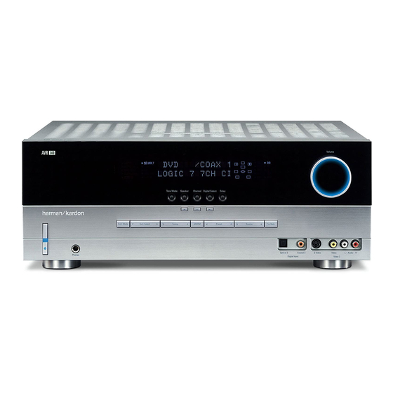
Page 5: Front-Panel Controls
3 Standby/On Switch: When the Main Power Switch 1 is “ON, ” press this button to turn on the AVR 140; press it again to turn the unit off. The Power Indicator 2 turns blue when the unit is on.
-
Page 6
NOTE: The AVR 140 is shipped with two covers that may be installed over the front-panel input jacks when they are not in use. -
Page 7: Rear-Panel Connections
+ or – terminals on your left and right speakers. When making speaker connections always make certain to maintain correct polarity by connecting the color-coded (white for front left and red for front right) (+) terminals on the AVR 140 to the red (+) ‡ fi ‹…
-
Page 8
DVD S-Video Input: Connect the S-video output of a DVD player or other video source to this jack. Bridge Digital Media Player (DMP) Connector: With the AVR 140 turned off, connect one end of the optional Harman Kardon Bridge to this connector. -
Page 9: Remote Control Functions
6-Channel/8-Channel Direct Input Mute NOTES: • The function names shown here are each button’s feature when used with the AVR 140. Most buttons have additional functions when used with other devices. See pages 41–42 for a list of these functions.
-
Page 10
AVR Selector: Pressing this button will switch the remote so that it will operate the AVR 140’s functions. If the AVR 140 is in the Standby mode, it will also turn the AVR 140 on. g AM/FM Tuner Select: Press this button to select the AVR 140’s tuner as the listening choice. -
Page 11
Disc Skip Button: This button has no direct function for the AVR 140 but is most often used to change to the next disc in a CD or DVD player when the remote is programmed for that type of device. -
Page 12: Installation And Connections
AVR 140. Note that it is not possible to use the AVR 140 in a 7.1-channel configuration. Any source information that the AVR receives or derives for the surround back left and right channels, e.g.
-
Page 13: Ac Power Connections
However, it will not convert composite or S signals to component video. • When connecting a video source to the AVR 140, you may use either composite, component or S- video, but only one type of video may be connect- ed for each device.
-
Page 14: System Configuration
SYSTEM CONFIGURATION When all audio, video and system connections have been made, the final steps before listening to your new AVR are to make the configuration adjustments that tailor the unit to the other components in your system as well as to accommodate your personal listening preferences.
-
Page 15: System Setup
You are now ready to power up the AVR 140 to begin these final adjustments. 1. Make certain that the AC Power Cord ‹…
-
Page 16: Using The On-Screen Display
“burned into” the projection tubes, plasma screen or CRT. This type of damage is not cov- ered by the AVR 140 warranty and may not be covered by the projector/TV set’s warranty. The AVR 140 has two on-screen display modes, “Semi-OSD”…
-
Page 17: Input Setup
Input Setup The first step in configuring the AVR 140 is to configure each input. Once an input is configured, all settings for the Digital Input, Component Video Input and Surround Mode will “attach”…
-
Page 18: Surround Setup
– you may change it later. However, to make it easier to establish the initial parameters for the AVR 140, it is best to select Dolby Pro Logic II or Logic 7 for most analog inputs. In the…
-
Page 19
DTS-ES Matrix mode through this menu to create a full eight-channel surround mode. When a DTS 96/24 signal is detected, the AVR 140 defaults to the DTS surround mode, but reproduces the higher-resolution materials that are present due to the higher sampling rate automatically. -
Page 20: Speaker Size
Speaker Size This menu tells the AVR 140 which type of speakers are in use. This is important as it adjusts the settings that decide whether your system will use the “5-chan- nel”…
-
Page 21
The surround back speakers need only be configured to be active once, and the AVR 140 will set them as active for all surround modes and sources. If you wish to set them as inactive for some sources, you may scroll down to the BASS MGR line of the SPEAKER SIZE menu and press the ‹/›… -
Page 22: Speaker Crossover Settings
The AVR 140’s advanced software enables you to quickly and easily set delay times without having to calculate them using a complex formula. All you need…
-
Page 23: Output Level Adjustment
Output level adjustment is a key part of the configura- tion of any surround sound product. It is particularly important for a digital receiver such as the AVR 140, as correct outputs ensure that you hear soundtracks with the proper directionality and intensity.
-
Page 24
Speaker/Channel Input Indicators . If the sound from a speaker location does NOT match the position indicated in the display, turn the AVR 140 off using the Main Power Switch and check the speaker wiring or connections to external power amplifiers to make certain that each speaker is connected to the correct output terminal. -
Page 25
SYSTEM CONFIGURATION Once the settings outlined on the previous pages have been made, the AVR 140 is ready for operation. While there are some additional settings to be made, these are best done after you have had an opportunity to lis- ten to a variety of sources and different kinds of pro- gram material. -
Page 26: Operation
Turning the AVR 140 On or Off • When using the AVR 140 for the first time, you must first press the Main Power Switch 1 on the front panel to turn the unit on. This places the unit in a Standby mode, as indicated by the amber color of the Power Indicator 2 .
-
Page 27: Surround Mode Selection
When the headphone plug is removed, the audio feed to the speakers will be restored. Surround Mode Selection One of the important features of the AVR 140 is its ability to reproduce a full multichannel surround sound field from digital sources, analog matrix surround- encoded programs and standard stereo programs.
-
Page 28: Surround Mode Chart
Logic 7 Cinema Exclusive to Harman Kardon for A/V receivers, Logic 7 is an advanced mode that extracts the maximum surround information from either surround- encoded programs or conventional stereo material. Depending on the number of speakers in use and the selection made in the SURROUND Logic 7 Music SELECT menu, the “5.1”…
-
Page 29
Surround Mode Chart Surround Mode Chart MODE FEATURES 5-Channel Stereo This mode takes advantage of multiple speakers to place a stereo signal at both the front and back of a room. Depending on whether the AVR 7-Channel Stereo has been configured for either 5.1 or 6.1/7.1 operation, one of these modes, but not both, is available at any time. Ideal for playing music in situations such as a party, it places the same signal at the front-left and surround-left, and front-right and surround-right speakers. -
Page 30
(HDTV) system. An optional, external RF demodulator is required to use the AVR 140 to listen to the Dolby Digital sound- tracks available on laser discs. Connect the RF output of the LD player to the demodulator and then connect the digital output of the demodulator to the Optical or Coaxial Inputs *(·d of the AVR 140. -
Page 31
DVD player (usually with the “Audio Select” button or in a menu screen on the disc) to send a full 5.1 feed to the AVR 140. It is also possible for the type of signal feed to change during the course of a DVD playback. -
Page 32
OPERATION Surround Mode Availability for Incoming Bitstreams and Audio Signals For incoming Dolby Digital signals, the following modes are available: Incoming Bitstream Available Surround Modes Dolby Digital 1/0/.0 or 1/0/.1 Dolby Digital, Dolby Digital Stereo, VMAx (N or F) Dolby Digital 2/0/.0 or 2/0/.1 Dolby Pro Logic II (Movie, Music or Game), Dolby Pro Logic, Dolby Digital, Dolby Pro Logic IIx** (Movie, Music or Game), VMAx (N or F) Dolby Digital 3/0/.0 or 3/0/.1 Dolby Digital, Dolby Digital Stereo, VMAx (N or F) -
Page 33: Tuner Operation
However, the digital signals will be passed through to the Digital Audio Outputs fl‡. Tuner Operation The AVR 140’s tuner is capable of tuning AM, FM and FM Stereo broadcast stations. Stations may be tuned manually, or they may be stored as favorite station presets and recalled from a 30-position memory.
-
Page 34: Using The Bridge
Repeat the procedure as needed until all channels requiring adjustment have been set. When all adjust- ments have been made and no further adjustments are made for five seconds, the AVR 140 will return to normal operation. The channel output for any input may also be adjusted using the full-OSD on-screen menu system.
-
Page 35
All changes to the front-panel brightness level are temporary; the displays will return to full brightness after the AVR is turned off and then on again. To return the displays to full brightness without turning the unit off, press the Dim Button as needed until the displays are on. -
Page 36: Advanced Features
Turn-On Volume Level As is the case with most audio/video receivers, when the AVR 140 is turned on, it will always return to the volume setting in effect when the unit was turned off. However, you may prefer to always have the AVR 140 turn on at a specific setting, regardless of what was last in use when the unit was turned off.
-
Page 37: Default Surround Mode
AVR for and the format of the incoming bitstream. The AVR 140 allows you to set the unit so that it will either use the default mode or switch to your desired mode. If you wish to set the AVR so that the surround mode information as it is encoded in the disc is always used, no further action is needed.
-
Page 38: Programming The Remote
002 in Step 4. Auto Search Method If the unit you wish to include in the AVR 140’s remote is not listed in the code tables in this manual or if the code does not seem to operate properly, you may wish…
-
Page 39: Programmed Device Functions
Function List and then look in the column for the device you are controlling. For example, button number 45 is the Direct button for the AVR 140, but it is the “Favorite” button for many cable television boxes and satellite receivers. Button number 31 is the Delay button for the AVR 140, but the Open/Close button for CD players.
-
Page 40: Volume Punch-Through
TV viewing, you may wish to have the AVR 140’s volume activated, although the remote is set to run the TV. Either the AVR 140 or TV volume control may be associated with any of the remote’s devices.
-
Page 41: Function List
Button Name AVR Function Power On Power On Power On Power Off Power Off Power Off Mute Mute Mute AVR Select AVR Select DVD Input Select DVD Select CD Input Select CD Select Tape Tape Input Select Tape Select VID 1 (VCR) Video 1 Select VCR Select VID 2 (CBL/SAT) Video 2 Select…
-
Page 42
FUNCTION LIST Button Name AVR Function Direct Direct Tuner Entry Angle Clear Clear Clear Preset Up Preset Tune Up Slow Forward Tuning Down Tuning Down Prev Chapter D. Skip Disc Skip (DVD) Disc Skip Preset Down Preset Tune Down Slow Rev Macro 1 Macro 1 Macro 2… -
Page 43: Setup Code Tables
CONCERTO CONTEC CORANDO CORONADO CRAIG CROWN CURTIS MATHES DAEWOO DAYTRON DIGI LINK DYNASTY DYNATECH ELECTROHOME EMERSON FUNAI FUTURETECH GOLDSTAR/LG GRUNDIG HALL MARK HARMAN KARDON HITACHI INFINITY INKEL JC PENNEY JENSEN KAWASHO KENWOOD LLOYTRON LODGENET SETUP CODE TABLE: TV SETUP CODES…
-
Page 44
SETUP CODE TABLE: TV Manufacturer/Brand Setup Code Number LOGIK LUXMAN MAGNAVOX MARANTZ MATSUI MEMOREX METZ MINERVA MITSUBISHI NATIONAL NIKEI ONKING ONWA OPTONICA ORION PANASONIC PHILCO PHILIPS PIONEER PORTLAND PROSCAN PROTON QUASAR RADIO SHACK REALISTIC RUNCO SAMPO SAMSUNG SANYO SCOTT SEARS SHARP SIEMENS SIGNATURE… -
Page 45
Manufacturer/Brand Setup Code Number TEKNIKA TELERENT TERA THOMSON TOSHIBA TOTEVISION VIDEO CONCEPTS VIDTECH WARDS YAMAHA YORK YUPITERU ZENITH ZONDA SETUP CODE TABLE: TV SETUP CODES… -
Page 46
DAYTRON 018 048 DYNATECH EMERSON 013 040 042 110 112 FISHER FUNAI 076 095 124 GO VIDEO GOLDSTAR/LG 018 107 HARMAN KARDON 018 049 HITACHI 040 048 JC PENNEY 018 045 JENSEN 018 048 111 132 KENWOOD 020 048 LLOYD… -
Page 47
Manufacturer/Brand Setup Code Number REALISTIC 017 020 040 045 159 SALORA SAMSUNG 045 051 095 105 109 SANSUI 048 116 147 SANYO 017 020 SCOTT 110 112 SEARS 017 020 SHARP 129 156 SONY 080 129 SOUNDESIGN SYLVANIA SYMPHONIC TANDY 017 040 TASHICO TATUNG… -
Page 48
AKAI AUDIO TECHNICA AUDIOACCESS AUDIOFILE CALIFORNIA AUDIO CAPETRONIC CARRERA CARVER CASIO CLARINETTE DENON EMERSON FISHER FRABA FUNAI GENEXXA GOLDSTAR/LG HAITAI HARMAN KARDON HITACHI INKEL JC PENNEY JENSEN KENWOOD LOTTE LUXMAN MAGNAVOX MARANTZ MCINTOSH MITSUMI MODULAIRE NAKAMICHI NIKKO ONKYO OPTIMUS PANASONIC… -
Page 49
YAMAHA YORK SETUP CODE TABLE: DVD Manufacturer/Brand Setup Code Number APEX DIGITAL DENON 019 051 003 004 GOLDSTAR/LG 005 055 064 066 HARMAN KARDON 001 002 MAGNAVOX MARANTZ MITSUBISHI ONKYO 009 048 PANASONIC 024 030 044 PHILIPS PIONEER 041 065… -
Page 50
SETUP CODE TABLE: SAT Manufacturer/Brand Setup Code Number ALPHASTAR ALPHASTAR DBS ALPHASTAR DSR BIRDVIEW CHANNEL MASTER 320 321 CHAPARRAL 315 316 CITOH DRAKE 313 317 DX ANTENNA 331 352 ECHOSTAR 395 397 ELECTRO HOME FUJITSU 324 329 GENERAL INSTRUMENT 303 311 HITACHI DBS HOUSTON TRACKER HUGHES… -
Page 51
Manufacturer/Brand Setup Code Number HARMAN KARDON SETUP CODE TABLE: CBL Manufacturer/Brand Setup Code Number 001 011 ALLEGRO AMERICAST ARCHER BELCOR CABLE STAR 033 113 CITIZEN COLOUR VOICE 085 090 DIGI EAGLE EASTERN 066 070 ELECTRICORD EMERSON FOCUS G.I. 001 011 017 096 097… -
Page 52
SETUP CODE TABLE: CBL Manufacturer/Brand Setup Code Number REMBRANT SAMSUNG 003 072 186 SCIENTIFIC ATLANTA 183 203 221 222 SEAM SIGNATURE 001 188 SPRUCER 053 081 177 189 STARCOM 002 011 163 STARGATE TANDY TELECAPATION TEXSCAN TIMELESS TOCOM 170 205 UNITED CABLE UNIVERSAL 033 034 039 042 113… -
Page 53: Troubleshooting Guide
In addition to the items shown above, additional information on troubleshooting possible problems with your AVR 140, or installation-related issues, may be found in the list of «Frequently Asked Questions» which is located in the Product Support section of our Web site at www.harmankardon.com.
-
Page 54: Technical Specifications
IF Rejection 90dB Supplied Accessories The following accessory items are supplied with the AVR 140. If any of these items are missing, please contact Harman Kardon customer service at www.harmankardon.com. • A system remote control • An FM wire antenna •…
-
Page 55: Trademark Acknowledgements
Installation Location 4 iPod ® 3, 11, 12, 34 IR Receiver (Remote Sensor) 5, 6 Logic 7 5, 6, 9, 11, 15, 16, 18, 19, 20, 21, 23, 24, 27, 28, 30, 32, 33, 37, 42, 54 Macros 11, 38…
-
Page 56: Appendix — Settings Worksheet
APPENDIX – SETTINGS WORKSHEET APPENDIX – SETTINGS WORKSHEET Table 1: Input Settings FEATURE VIDEO 1 Input Title Component Video Input Component Component Video 1 (Y/N) Video2 (Y/N) Digital Audio Input Auto Poll (On/Off) Surround Mode Night Mode † Front L/R Speaker Size Center Speaker Size †…
-
Page 57
NOTES NOTES… -
Page 58
NOTES NOTES NOTES… -
Page 59
STAPLE INVOICE HERE… -
Page 60
® Power for the Digital Revolution ® 250 Crossways Park Drive, Woodbury, New York 11797 www.harmankardon.com © 2006 Harman International Industries, Incorporated. All rights reserved. Part No. CQX1A1025Z 3/06…
-
Страница 1
A VR 140 Audio/ V ideo Receiver OWNER’S MANU AL Power for the Digital Revolution ® 25339_AVR140_Eng_2 30/08/05 9:55 Side 1[…]
-
Страница 2
2 T ABLE OF CONTENTS 3 Introduction 4 Safety Information 4 Unpacking 5 F ront Panel Controls 7 Rear P anel Connections 9 Main Remote Control Functions 12 Installation and Connections 12 Audio Connections 12 Video Connections 13 SCAR T A/V Connections 14 System and P ower Connections 15 Speak er Selection 15 Speak er Placement 16 System Configuratio[…]
-
Страница 3
INTRODUCTION 3 Introduction Thank you for choosing Harman Kardon! With the purchase of a Harman Kardon A VR 140 you are about to begin many years of listening enjoyment. Designed to provide all the excitement and detail of movie soundtracks and every nuance of musical selections , the A VR 140 is truly a multichannel receiver for the new millennium[…]
-
Страница 4
4 SAFETY INFORMA TION Safety Information Important Safety Information V erify Line V oltage Before Use Y our A VR has been designed for use with 220- 240-V olt A C current. Connection to a line voltage other than that for which it is intended can create a safety and fire hazard and may damage the unit. If you have any questions about the voltage re[…]
-
Страница 5
FRONT P ANEL CONTROLS 5 1 Main P ower Switch: Press this button to apply power to the A VR. When the switch is pressed in, the unit is placed in a Standby mode , as indicated by the orange LED 3 . T his button MUST be pressed in to operate the unit. T o turn the unit off completely and prevent the use of the remote control, this switch should be pr[…]
-
Страница 6
6 FRONT P ANEL CONTROLS Front P anel Controls 7 Selector Buttons: When you are establishi ng the A VR’ s configuration settings , use these buttons to select from the choices available , as shown in the Main Information Display Ò . 8 T one Mode: Pressing this button enables or disables the Balance , Bass and T reble tone controls . When the butt[…]
-
Страница 7
REAR P ANEL CONNECTIONS 7 Rear P anel Connections AM Antenna FM Antenna T ape Inputs T ape Outputs Subwoofer Output DVD Audio Inputs CD Inputs Video 1 Audio Outputs DMP Connector 8-Channel Direct Inputs Digital Audio Outputs Video[…]
-
Страница 8
8 REAR P ANEL CONNECTIONS Rear P anel Connections Digital Audio Outputs: Connect these jacks to the matching digital input connector on a digital recorder such as a CD-R or MiniDisc recorder . Video Monitor Outputs: Connect this jack to the composite and/or S-Video input of a TV monitor or video projector to view the on-screen menus and the[…]
-
Страница 9
0 1 2 3 4 5 6 7 8 9 A B C D E F G H I J K L M N O P Q ! » # $ % & ‘ ( ) * + , MAIN REMO TE CONTROL FUNCTIONS 9 Main Remote Control Functions P ower Off Button IR T ransmitter Window Program Indicator P ower On Button Input Selectors A VR Selector AM/FM T uner Select 6-Channel/8-Channel Direct Input T est Button Sleep Butto[…]
-
Страница 10
10 MAIN REMO TE CONTROL FUNCTIONS Main Remote Control Functions IMPORT ANT NOTE: The A VR 140’ s remote may be programmed to control up to seven devices , including the A VR. Before using the remote , it is important to remember to press the Input Selector button 4 that corresponds to the unit you wish to operate . In addition, the A VR’ s remo[…]
-
Страница 11
MAIN REMO TE CONTROL FUNCTIONS 11 M Dolby Mode Selector: This button is used to select one of the available Dolby Surround processing modes . Each press of this button will select one of the Dolby Pro Logic II modes , Dolby 3 Stereo or Dolby Digital. Note that the Dolby Digital mode is only available with a digital input selected and the other mode[…]
-
Страница 12
12 INST ALLATION AND CONNECTIONS After unpacking the unit, and placing it on a solid surface capable of supporting its weight, you will need to mak e the connections to your audio and video equipment. Audio Equipment Connections We recommend that you use high-quality inter- connect cables when making connections to source equipment and recorders to[…]
-
Страница 13
INST ALLATION AND CONNECTIONS 13 Installation and Connections viewed on the TV screen in any case, with Video or S-V ideo input selected on the TV . • When the component video jacks are used, the on-screen menus will not be visible . Y ou must switch to the standard composite or S-Video input on your TV to view those menus . • All component inp[…]
-
Страница 14
14 INST ALLATION AND CONNECTIONS Installation and Connections Figure 1: SCART/Cinch-Adapter f or playbac k; signal flow: SCART → Cinch Figure 2: SCART/Cinch-Adapter f or record and playbac k; signal flow: SCART ↔ Cinch Figure 3: Cinch/SCART -Adapter for playbac k; signal flow: Cinch → SCART Figure 4: SCART/S-Video Adapter for pla yback; signa[…]
-
Страница 15
INST ALLATION AND CONNECTIONS 15 Installation and Connections Speaker Selection No matter which type or brand of speak ers is used, the same model or brand of speak er should be used for the front-left, center and front-right speak ers. T his creates a seamless front soundstage and eliminates the possibility of distracting sonic disturbances that o[…]
-
Страница 16
16 SY STEM CONFIGURATION System Configuration Once the speak ers have been placed in the room and connected, the remaining steps are to pro- gram the system configur ation memories. With the A VR two kind of memories are used, those associated individually with the input selected, e .g. surround modes , and others working global- ly for all inputs […]
-
Страница 17
SY STEM CONFIGURATION 17 T o make this process as quick and as easy as pos- sible , we suggest that you use the full-OSD sys- tem with the on-screen menus , and step through each input. It is recommended that you record your settings for each input using the work-sheets in the appendix to this manual, in the event there is a power loss or if you ne[…]
-
Страница 18
18 SY STEM CONFIGURATION System Configuration to digital sources . In the case of inputs such as a CD Player , T ape Deck or T uner , you may wish to set the mode to Stereo , if that is your preferred listening mode for standard stereo sources , where it is unlik ely that sur round encoded material will be used. Alternatively, the 5 Channel Stereo […]
-
Страница 19
SY STEM CONFIGURATION 19 Figure 5 T o adjust the Night mode setting, mak e certain that the ➞ cursor is on the NIGHT line of the DOLBY menu. Next, press ‹ / › Buttons E to choose between the following set- tings . OFF : When OFF is highlighted, the Night mode will not function. MID : When MID is in the highlighted video, a mild compression[…]
-
Страница 20
20 SY STEM CONFIGURATION System Configuration going to the front left/right speak ers, or you may configure it so that the subwoofer feed is activated. T he factory default setting is to have the sub- woofer turned off for this mode , but you may change that setting by following these steps: 1. Press the Speaker Button 6 ‘ . 2. Press the Set B[…]
-
Страница 21
SY STEM CONFIGURATION 21 System Configuration the SUBWOOFER line in this menu (see below), the front left and right bass information may also be directed to the subwoofer . NO TE: When the front speakers are set to the LARGE option and the surround mode is set to «Surround Off», or pure two-channel stereo , when an analog signal source is[…]
-
Страница 22
22 SY STEM CONFIGURATION System Configuration option is selected, a full-range signal will be sent to the front left/right “main” speak ers. T he subwoofer will receive the front left and right bass frequencies under the crossover fre- quency selected in another setting on this menu, as described below , and also the LFE soundtrack. 9. When all[…]
-
Страница 23
SY STEM CONFIGURATION 23 System Configuration pensate for this difference through the use of the delay settings to adjust the timing for the specific speak er placement and acoustic conditions in your listening room or home theater . T o re-synchronize the front, center and surround channels at first measure and note the distance from the listening[…]
-
Страница 24
24 SY STEM CONFIGURATION System Configuration Before beginning the output level adjustment process , mak e certain that all speaker connec- tions have been properly made . The system volume should be turned down at first. F or the easiest set-up, follow these steps while seated in the listening position that will be used most often: 1. Mak e certai[…]
-
Страница 25
SY STEM CONFIGURATION 25 System Configuration various sources , as opposed to the test tone . See page 31 for more information on trimming the output levels to external source material. NO TE: The subwoofer output level is not adjustable using the test tone . To change the subwoofer level, follow the steps for Output Level T rim Adjustment on page […]
-
Страница 26
26 OPERA TION Operation Surround Mode Chart MODE FEA TURES DOLBY DIGIT AL Available only with digital input sources encoded with Dolby Digital data. It provides up to five separate main audio channels and a special dedicated Low F requency Effects channel. DOLBY DIGIT AL EX Available when the receiver is configured for 6.1/7.1 channel oper ation, D[…]
-
Страница 27
OPERA TION 27 Operation Surround Mode Chart MODE FEA TURES DTS Neo:6 Cinema T hese two modes are available when any analog source is playing to create a six-channel DTS Neo:6 Music surround presentation from conventional Matrix-encoded and traditional Stereo sources . Select the Cinema version of Neo:6 when a program with any type of analog Matrix […]
-
Страница 28
28 OPERA TION Operation Basic Operation Once you have completed the setup and configu- ration of the A VR, it is simple to oper ate and enjoy . T he following instructions should be followed for you to maximize your enjoyment of your new receiver: T urning the A VR On or Off • When using the AVR for the first time , you must press the Main P ower[…]
-
Страница 29
OPERA TION 29 Operation • To set the output of the A VR so that the output is “flat, ” with the tone and balance controls de- activated, press the T one Mode button 8 once or twice so that the words Tone Off appear momentarily in the Main Information Display Ò . To return the tone controls to an active con- dition, press the T one Mode 8 but[…]
-
Страница 30
30 OPERA TION Operation DTS-encoded sound tracks are av ailable on select DVD and LD discs , as well as on special audio- only DTS CDs . Y ou may use any LD , DVD or CD player equipped with a digital output to play DTS- encoded special audio-only CDs with the A VR, but DTS-LDs can be played on LD players and DTS-DVDs on DVD players only . All that […]
-
Страница 31
OPERA TION 31 Operation lock onto , and is thus “unlocked. ” Y ou may see this message when a DVD is first started until the stream is playing and the processor determines which mode to apply; or any time the data stream is stopped or paused, such as when the menus of some discs are displayed or when the player is switching between the differen[…]
-
Страница 32
32 OPERA TION Operation Important Note: When a digital surround source (Dolby Digital, DTS) is played, the letters SBL/SBR for the Surround Back channels will appear only when a DTS ES DISCRETE 6.1 source is played. Then this surround mode will be indi- cated in the front display and on-screen display . With all other recordings the icons for the s[…]
-
Страница 33
OPERA TION 33 Advanced Featur es Operation T o adjust the output levels using program materi- al, first select the surround mode for which you want to trim the speak ers (see NOTE below), start your program material source and set the reference volume for the front left and front right channels using the V olume Control ) . Once the reference level[…]
-
Страница 34
34 INTRODUCTION / ADV ANCED FEATURES T urn On V olume Level As is the case with most audio/video receivers , when the A VR is turned on, it will always return to the volume setting in effect when the unit was turned off . However , you may prefer to always have the A VR turn on at a specific set- ting, regardless of what was last in use when the un[…]
-
Страница 35
TUNER OPERA TION 35 T uner Operation Default Surround Mode In normal operation, when the AVR senses a Dolby Digital or DTS digital audio data stream, it will automatically switch the appropriate default surround mode , with the A VR responding to the data flags that are encoded on the DVD disc or in the digital video broadcast. In most cases , this[…]
-
Страница 36
36 TUNER OPERA TION RDS Operation T he A VR 140 is equipped with RDS (Radio Data System), which brings a wide range of informa- tion to FM radio . Now in use in many countries , RDS is a system for transmitting station call signs or network information, a description of station program type , text messages about the station or specifics of a musica[…]
-
Страница 37
PROGRAMMING THE REMO TE 37 Progr amming the Remote T he A VR 140 is equipped with a powerful remote control that will control not only the receiver’ s functions , but also most popular brands of audio and video equipment, including CD players , TV sets , cable boxes , VCRs, satellite receivers and other home-theater equipment. Once the A VR’s r[…]
-
Страница 38
38 PROGRAMMING THE REMO TE F or future reference enter the Setup Codes for the equipment in your system here: DVD ____________ CD ________________ VID1/VCR ________ VID3/TV __________ VID2/CBL/SA T ______________________ T APE ______________________________ Macro Progr amming Macros enable you to easily repeat frequently used combinations of comman[…]
-
Страница 39
PROGRAMMING THE REMO TE 39 Progr amming the Remote 3. Press either the A VR Selector 5 or the Input Selector 4 , depending on which system’ s volume control you wish to have attached for the punch-through mode . T he Program Indicator 2 will blink green three times and then go out to confirm the data entry . Example: T o have the A VR’ s volume[…]
-
Страница 40
40 FUNCTION LIST Function List No . Button Name A VR Function DVD CD/CDR 1 P ower On P ower On P ower On P ower On 2 P ower Off P ower Off P ower Off P ower Off 3 Mute Mute 4 AV R A VR Select 5 DVD DVD Input Select DVD Select 6 CD CD Input Select CD Select 7 T ape T ape Input Select 8 VID 1 Video 1 Select 9 VID 2 Video 2 Select 10 VID 3 Video 3 Sel[…]
-
Страница 41
FUNCTION LIST 41 Function List No . Button Name T ape VCR (VID 1) TV (VID 2) CBL (VID 3) SA T(VID 3) (DMP) 1 P ower On P ower On Power On Power On P ower On P ower On 2 P ower Off Power Off P ower Off P ower Off P ower Off P ower Off 3 Mute Mute 4 AV R 5 DVD 6 CD 7 T ape T ape Select 8 VID 1 VCR Select 9 VID 2 TV Select 10 VID 3 VID 3 Select VID 3 […]
-
Страница 42
42 TROUBLESHOO TING GUIDE T roubleshooting Guide Processor Reset In the rare case where the unit’ s operation or the displays seem abnormal, the cause may involve the erratic oper ation of the system’s memory or microprocessor . T o correct this problem, first unplug the unit from the AC wall outlet and w ait at least three minutes . After the […]
-
Страница 43
TECHNICAL SPECIFICA TIONS 43 T echnical Specifications Audio Section Stereo Mode Continuous Average P ower (FTC) 50 Watts per channel, 20Hz–20kHz, @ < 0.07% THD, both channels driven into 8 ohms 6 Channel Surround Modes P ower Per Individual Channel F ront L&R channels: 40 Watts per channel, @ < 0.07% THD, 20Hz–20kHz into 8 ohms Cente[…]
-
Страница 44
44 APPENDIX APPENDIX – SETTINGS W ORKSHEET FEA TURE DVD VIDEO 1 VIDEO 2 VIDEO 3 DMP CD T APE TUNER 6/8 CH. DIRECT Input Title –––––––– Component Video Input Component Component Component Component –––––––––– Component Component Component Component Video 1 (Y/N) Video2 (Y/N) Video 2 (Y/N) Video 2 (Y/N) Video 1 ([…]
-
Страница 45
INTRODUCTION 45 25339_AVR140_Eng_2 30/08/05 9:56 Side 45[…]
-
Страница 46
250 Crossways P ark Drive, W oodbury, New Y ork 11797 www .harmankardon.com Harman Consumer Group International: 2, route de Tours , 72500 Château-du-Loir , France © 2005 Harman Kardon, Incorporated P art No.: OM P/N CQX1A1055Z 25339_AVR140_Eng_2 30/08/05 9:56 Side 46[…]
-
Harman Kardon AVR 140 — page 1
A VR 140 Audio/ V ideo Receiver OWNER’S MANU AL Power for the Digital Revolution ® 25339_AVR140_Eng_2 30/08/05 9:55 Side 1 …
-
Harman Kardon AVR 140 — page 2
2 T ABLE OF CONTENTS 3 Introduction 4 Safety Information 4 Unpacking 5 F ront Panel Controls 7 Rear P anel Connections 9 Main Remote Control Functions 12 Installation and Connections 12 Audio Connections 12 Video Connections 13 SCAR T A/V Connections 14 System and P ower Connections 15 Speak er Selection 15 Speak er Placement 16 System Configuratio …
-
Harman Kardon AVR 140 — page 3
INTRODUCTION 3 Introduction Thank you for choosing Harman Kardon! With the purchase of a Harman Kardon A VR 140 you are about to begin many years of listening enjoyment. Designed to provide all the excitement and detail of movie soundtracks and every nuance of musical selections , the A VR 140 is truly a multichannel receiver for the new millennium …
-
Harman Kardon AVR 140 — page 4
4 SAFETY INFORMA TION Safety Information Important Safety Information V erify Line V oltage Before Use Y our A VR has been designed for use with 220- 240-V olt A C current. Connection to a line voltage other than that for which it is intended can create a safety and fire hazard and may damage the unit. If you have any questions about the voltage re …
-
Harman Kardon AVR 140 — page 5
FRONT P ANEL CONTROLS 5 1 Main P ower Switch: Press this button to apply power to the A VR. When the switch is pressed in, the unit is placed in a Standby mode , as indicated by the orange LED 3 . T his button MUST be pressed in to operate the unit. T o turn the unit off completely and prevent the use of the remote control, this switch should be pr …
-
Harman Kardon AVR 140 — page 6
6 FRONT P ANEL CONTROLS Front P anel Controls 7 Selector Buttons: When you are establishi ng the A VR’ s configuration settings , use these buttons to select from the choices available , as shown in the Main Information Display Ò . 8 T one Mode: Pressing this button enables or disables the Balance , Bass and T reble tone controls . When the butt …
-
Harman Kardon AVR 140 — page 7
REAR P ANEL CONNECTIONS 7 Rear P anel Connections AM Antenna FM Antenna T ape Inputs T ape Outputs Subwoofer Output DVD Audio Inputs CD Inputs Video 1 Audio Outputs DMP Connector 8-Channel Direct Inputs Digital Audio Outputs Video …
-
Harman Kardon AVR 140 — page 8
8 REAR P ANEL CONNECTIONS Rear P anel Connections Digital Audio Outputs: Connect these jacks to the matching digital input connector on a digital recorder such as a CD-R or MiniDisc recorder . Video Monitor Outputs: Connect this jack to the composite and/or S-Video input of a TV monitor or video projector to view the on-screen menus and the …
-
Harman Kardon AVR 140 — page 9
0 1 2 3 4 5 6 7 8 9 A B C D E F G H I J K L M N O P Q ! » # $ % & ‘ ( ) * + , MAIN REMO TE CONTROL FUNCTIONS 9 Main Remote Control Functions P ower Off Button IR T ransmitter Window Program Indicator P ower On Button Input Selectors A VR Selector AM/FM T uner Select 6-Channel/8-Channel Direct Input T est Button Sleep Butto …
-
Harman Kardon AVR 140 — page 10
10 MAIN REMO TE CONTROL FUNCTIONS Main Remote Control Functions IMPORT ANT NOTE: The A VR 140’ s remote may be programmed to control up to seven devices , including the A VR. Before using the remote , it is important to remember to press the Input Selector button 4 that corresponds to the unit you wish to operate . In addition, the A VR’ s remo …
-
Harman Kardon AVR 140 — page 11
MAIN REMO TE CONTROL FUNCTIONS 11 M Dolby Mode Selector: This button is used to select one of the available Dolby Surround processing modes . Each press of this button will select one of the Dolby Pro Logic II modes , Dolby 3 Stereo or Dolby Digital. Note that the Dolby Digital mode is only available with a digital input selected and the other mode …
-
Harman Kardon AVR 140 — page 12
12 INST ALLATION AND CONNECTIONS After unpacking the unit, and placing it on a solid surface capable of supporting its weight, you will need to mak e the connections to your audio and video equipment. Audio Equipment Connections We recommend that you use high-quality inter- connect cables when making connections to source equipment and recorders to …
-
Harman Kardon AVR 140 — page 13
INST ALLATION AND CONNECTIONS 13 Installation and Connections viewed on the TV screen in any case, with Video or S-V ideo input selected on the TV . • When the component video jacks are used, the on-screen menus will not be visible . Y ou must switch to the standard composite or S-Video input on your TV to view those menus . • All component inp …
-
Harman Kardon AVR 140 — page 14
14 INST ALLATION AND CONNECTIONS Installation and Connections Figure 1: SCART/Cinch-Adapter f or playbac k; signal flow: SCART → Cinch Figure 2: SCART/Cinch-Adapter f or record and playbac k; signal flow: SCART ↔ Cinch Figure 3: Cinch/SCART -Adapter for playbac k; signal flow: Cinch → SCART Figure 4: SCART/S-Video Adapter for pla yback; signa …
-
Harman Kardon AVR 140 — page 15
INST ALLATION AND CONNECTIONS 15 Installation and Connections Speaker Selection No matter which type or brand of speak ers is used, the same model or brand of speak er should be used for the front-left, center and front-right speak ers. T his creates a seamless front soundstage and eliminates the possibility of distracting sonic disturbances that o …
-
Harman Kardon AVR 140 — page 16
16 SY STEM CONFIGURATION System Configuration Once the speak ers have been placed in the room and connected, the remaining steps are to pro- gram the system configur ation memories. With the A VR two kind of memories are used, those associated individually with the input selected, e .g. surround modes , and others working global- ly for all inputs …
-
Harman Kardon AVR 140 — page 17
SY STEM CONFIGURATION 17 T o make this process as quick and as easy as pos- sible , we suggest that you use the full-OSD sys- tem with the on-screen menus , and step through each input. It is recommended that you record your settings for each input using the work-sheets in the appendix to this manual, in the event there is a power loss or if you ne …
-
Harman Kardon AVR 140 — page 18
18 SY STEM CONFIGURATION System Configuration to digital sources . In the case of inputs such as a CD Player , T ape Deck or T uner , you may wish to set the mode to Stereo , if that is your preferred listening mode for standard stereo sources , where it is unlik ely that sur round encoded material will be used. Alternatively, the 5 Channel Stereo …
-
Harman Kardon AVR 140 — page 19
SY STEM CONFIGURATION 19 Figure 5 T o adjust the Night mode setting, mak e certain that the ➞ cursor is on the NIGHT line of the DOLBY menu. Next, press ‹ / › Buttons E to choose between the following set- tings . OFF : When OFF is highlighted, the Night mode will not function. MID : When MID is in the highlighted video, a mild compression …
-
Harman Kardon AVR 140 — page 20
20 SY STEM CONFIGURATION System Configuration going to the front left/right speak ers, or you may configure it so that the subwoofer feed is activated. T he factory default setting is to have the sub- woofer turned off for this mode , but you may change that setting by following these steps: 1. Press the Speaker Button 6 ‘ . 2. Press the Set B …
-
Harman Kardon AVR 140 — page 21
SY STEM CONFIGURATION 21 System Configuration the SUBWOOFER line in this menu (see below), the front left and right bass information may also be directed to the subwoofer . NO TE: When the front speakers are set to the LARGE option and the surround mode is set to «Surround Off», or pure two-channel stereo , when an analog signal source is …
-
Harman Kardon AVR 140 — page 22
22 SY STEM CONFIGURATION System Configuration option is selected, a full-range signal will be sent to the front left/right “main” speak ers. T he subwoofer will receive the front left and right bass frequencies under the crossover fre- quency selected in another setting on this menu, as described below , and also the LFE soundtrack. 9. When all …
-
Harman Kardon AVR 140 — page 23
SY STEM CONFIGURATION 23 System Configuration pensate for this difference through the use of the delay settings to adjust the timing for the specific speak er placement and acoustic conditions in your listening room or home theater . T o re-synchronize the front, center and surround channels at first measure and note the distance from the listening …
-
Harman Kardon AVR 140 — page 24
24 SY STEM CONFIGURATION System Configuration Before beginning the output level adjustment process , mak e certain that all speaker connec- tions have been properly made . The system volume should be turned down at first. F or the easiest set-up, follow these steps while seated in the listening position that will be used most often: 1. Mak e certai …
-
Harman Kardon AVR 140 — page 25
SY STEM CONFIGURATION 25 System Configuration various sources , as opposed to the test tone . See page 31 for more information on trimming the output levels to external source material. NO TE: The subwoofer output level is not adjustable using the test tone . To change the subwoofer level, follow the steps for Output Level T rim Adjustment on page …
-
Harman Kardon AVR 140 — page 26
26 OPERA TION Operation Surround Mode Chart MODE FEA TURES DOLBY DIGIT AL Available only with digital input sources encoded with Dolby Digital data. It provides up to five separate main audio channels and a special dedicated Low F requency Effects channel. DOLBY DIGIT AL EX Available when the receiver is configured for 6.1/7.1 channel oper ation, D …
-
Harman Kardon AVR 140 — page 27
OPERA TION 27 Operation Surround Mode Chart MODE FEA TURES DTS Neo:6 Cinema T hese two modes are available when any analog source is playing to create a six-channel DTS Neo:6 Music surround presentation from conventional Matrix-encoded and traditional Stereo sources . Select the Cinema version of Neo:6 when a program with any type of analog Matrix …
-
Harman Kardon AVR 140 — page 28
28 OPERA TION Operation Basic Operation Once you have completed the setup and configu- ration of the A VR, it is simple to oper ate and enjoy . T he following instructions should be followed for you to maximize your enjoyment of your new receiver: T urning the A VR On or Off • When using the AVR for the first time , you must press the Main P ower …
-
Harman Kardon AVR 140 — page 29
OPERA TION 29 Operation • To set the output of the A VR so that the output is “flat, ” with the tone and balance controls de- activated, press the T one Mode button 8 once or twice so that the words Tone Off appear momentarily in the Main Information Display Ò . To return the tone controls to an active con- dition, press the T one Mode 8 but …
-
Harman Kardon AVR 140 — page 30
30 OPERA TION Operation DTS-encoded sound tracks are av ailable on select DVD and LD discs , as well as on special audio- only DTS CDs . Y ou may use any LD , DVD or CD player equipped with a digital output to play DTS- encoded special audio-only CDs with the A VR, but DTS-LDs can be played on LD players and DTS-DVDs on DVD players only . All that …
-
Harman Kardon AVR 140 — page 31
OPERA TION 31 Operation lock onto , and is thus “unlocked. ” Y ou may see this message when a DVD is first started until the stream is playing and the processor determines which mode to apply; or any time the data stream is stopped or paused, such as when the menus of some discs are displayed or when the player is switching between the differen …
-
Harman Kardon AVR 140 — page 32
32 OPERA TION Operation Important Note: When a digital surround source (Dolby Digital, DTS) is played, the letters SBL/SBR for the Surround Back channels will appear only when a DTS ES DISCRETE 6.1 source is played. Then this surround mode will be indi- cated in the front display and on-screen display . With all other recordings the icons for the s …
-
Harman Kardon AVR 140 — page 33
OPERA TION 33 Advanced Featur es Operation T o adjust the output levels using program materi- al, first select the surround mode for which you want to trim the speak ers (see NOTE below), start your program material source and set the reference volume for the front left and front right channels using the V olume Control ) . Once the reference level …
-
Harman Kardon AVR 140 — page 34
34 INTRODUCTION / ADV ANCED FEATURES T urn On V olume Level As is the case with most audio/video receivers , when the A VR is turned on, it will always return to the volume setting in effect when the unit was turned off . However , you may prefer to always have the A VR turn on at a specific set- ting, regardless of what was last in use when the un …
-
Harman Kardon AVR 140 — page 35
TUNER OPERA TION 35 T uner Operation Default Surround Mode In normal operation, when the AVR senses a Dolby Digital or DTS digital audio data stream, it will automatically switch the appropriate default surround mode , with the A VR responding to the data flags that are encoded on the DVD disc or in the digital video broadcast. In most cases , this …
-
Harman Kardon AVR 140 — page 36
36 TUNER OPERA TION RDS Operation T he A VR 140 is equipped with RDS (Radio Data System), which brings a wide range of informa- tion to FM radio . Now in use in many countries , RDS is a system for transmitting station call signs or network information, a description of station program type , text messages about the station or specifics of a musica …
-
Harman Kardon AVR 140 — page 37
PROGRAMMING THE REMO TE 37 Progr amming the Remote T he A VR 140 is equipped with a powerful remote control that will control not only the receiver’ s functions , but also most popular brands of audio and video equipment, including CD players , TV sets , cable boxes , VCRs, satellite receivers and other home-theater equipment. Once the A VR’s r …
-
Harman Kardon AVR 140 — page 38
38 PROGRAMMING THE REMO TE F or future reference enter the Setup Codes for the equipment in your system here: DVD ____________ CD ________________ VID1/VCR ________ VID3/TV __________ VID2/CBL/SA T ______________________ T APE ______________________________ Macro Progr amming Macros enable you to easily repeat frequently used combinations of comman …
-
Harman Kardon AVR 140 — page 39
PROGRAMMING THE REMO TE 39 Progr amming the Remote 3. Press either the A VR Selector 5 or the Input Selector 4 , depending on which system’ s volume control you wish to have attached for the punch-through mode . T he Program Indicator 2 will blink green three times and then go out to confirm the data entry . Example: T o have the A VR’ s volume …
-
Harman Kardon AVR 140 — page 40
40 FUNCTION LIST Function List No . Button Name A VR Function DVD CD/CDR 1 P ower On P ower On P ower On P ower On 2 P ower Off P ower Off P ower Off P ower Off 3 Mute Mute 4 AV R A VR Select 5 DVD DVD Input Select DVD Select 6 CD CD Input Select CD Select 7 T ape T ape Input Select 8 VID 1 Video 1 Select 9 VID 2 Video 2 Select 10 VID 3 Video 3 Sel …
-
Harman Kardon AVR 140 — page 41
FUNCTION LIST 41 Function List No . Button Name T ape VCR (VID 1) TV (VID 2) CBL (VID 3) SA T(VID 3) (DMP) 1 P ower On P ower On Power On Power On P ower On P ower On 2 P ower Off Power Off P ower Off P ower Off P ower Off P ower Off 3 Mute Mute 4 AV R 5 DVD 6 CD 7 T ape T ape Select 8 VID 1 VCR Select 9 VID 2 TV Select 10 VID 3 VID 3 Select VID 3 …
-
Harman Kardon AVR 140 — page 42
42 TROUBLESHOO TING GUIDE T roubleshooting Guide Processor Reset In the rare case where the unit’ s operation or the displays seem abnormal, the cause may involve the erratic oper ation of the system’s memory or microprocessor . T o correct this problem, first unplug the unit from the AC wall outlet and w ait at least three minutes . After the …
-
Harman Kardon AVR 140 — page 43
TECHNICAL SPECIFICA TIONS 43 T echnical Specifications Audio Section Stereo Mode Continuous Average P ower (FTC) 50 Watts per channel, 20Hz–20kHz, @ < 0.07% THD, both channels driven into 8 ohms 6 Channel Surround Modes P ower Per Individual Channel F ront L&R channels: 40 Watts per channel, @ < 0.07% THD, 20Hz–20kHz into 8 ohms Cente …
-
Harman Kardon AVR 140 — page 44
44 APPENDIX APPENDIX – SETTINGS W ORKSHEET FEA TURE DVD VIDEO 1 VIDEO 2 VIDEO 3 DMP CD T APE TUNER 6/8 CH. DIRECT Input Title –––––––– Component Video Input Component Component Component Component –––––––––– Component Component Component Component Video 1 (Y/N) Video2 (Y/N) Video 2 (Y/N) Video 2 (Y/N) Video 1 ( …
-
Harman Kardon AVR 140 — page 45
INTRODUCTION 45 25339_AVR140_Eng_2 30/08/05 9:56 Side 45 …
-
Harman Kardon AVR 140 — page 46
250 Crossways P ark Drive, W oodbury, New Y ork 11797 www .harmankardon.com Harman Consumer Group International: 2, route de Tours , 72500 Château-du-Loir , France © 2005 Harman Kardon, Incorporated P art No.: OM P/N CQX1A1055Z 25339_AVR140_Eng_2 30/08/05 9:56 Side 46 …
-
Инструкции по эксплуатации
1

Harman-Kardon AVR 140 инструкция по эксплуатации
(46 страниц)
- Языки:Английский
-
Тип:
PDF -
Размер:
1.07 MB
Просмотр
На NoDevice можно скачать инструкцию по эксплуатации для Harman-Kardon AVR 140. Руководство пользователя необходимо для ознакомления с правилами установки и эксплуатации Harman-Kardon AVR 140. Инструкции по использованию помогут правильно настроить Harman-Kardon AVR 140, исправить ошибки и выявить неполадки.

249 ₽
Инструкция (руководство пользователя) на Аудио/видео ресивер Harman Kardon AVR-140
Артикул: harman-kardon-avr-140
Категория: Harman Kardon
-
Описание
-
Детали
Описание
Инструкцию по эксплуатации Harman Kardon AVR-140 на русском языке можно будет скачать в личном кабинете после оформления и оплаты заказа.
Детали
| Формат файла |
|
|---|---|
| Размер инструкции в кб |
1317 |