haas руководство оператора (Токарный станок — руководство оператора)
PDF-файл haas руководство оператора (Токарный станок — руководство оператора) Металлорежущее оборудование (121472): Книга — в нескольких семестрахhaas руководство оператора (Токарный станок — руководство оператора) — PDF (121472) — СтудИзба2022-05-032022-05-03Bro_EngineerСтудИзба
Описание файла
PDF-файл из архива «Токарный станок — руководство оператора»,
который расположен в категории «».
Всё это находится в предмете «металлорежущее оборудование» из , которые можно найти в файловом архиве МГТУ им. Н.Э.Баумана.
Не смотря на прямую связь этого архива с МГТУ им. Н.Э.Баумана, его также можно найти и в других разделах. .
Просмотр PDF-файла онлайн
Текст из PDF
Свежие статьи
Популярно сейчас
Предложите, как улучшить StudyLib
(Для жалоб на нарушения авторских прав, используйте
другую форму
)
Ваш е-мэйл
Заполните, если хотите получить ответ
Оцените наш проект
1
2
3
4
5
-
Contents
-
Table of Contents
-
Bookmarks
Quick Links
Haas Factory Outlet
A Division of Productivity Inc
CNC Lathe Series
Training Manual
Haas TL Series
Tool Room Lathe Operator
Revised 06-2012
Related Manuals for Haas TL Series
Summary of Contents for Haas TL Series
-
Page 1
Haas Factory Outlet A Division of Productivity Inc CNC Lathe Series Training Manual Haas TL Series Tool Room Lathe Operator Revised 06-2012… -
Page 2
This Manual is the Property of Productivity Inc The document may not be reproduced without the express written permission of Productivity Inc. The content must not be altered, nor may the Productivity Inc name be removed from the materials. This material is to be used as a guide to operation of the machine tool. The Operator is responsible for following Safety Procedures as outlined by their instructor or manufacturer s specifications. -
Page 3: Table Of Contents
Tool Room Lathe Operator Training Manual Table of Contents THE CARTESIAN COORDINATE SYSTEM ………………….4 MACHINE HOME POSITION ……………………..7 THE HAAS CNC CONTROL ……………………..9 CONTROL DISPLAY……………………….10 KEYBOARD INTRODUCTION ……………………..11 UNCTION ……………………….12 …………………………12 VERRIDE ……………………….13 ISPLAY …………………………
-
Page 4: Table Of Contents
For more information on Additional Training Opportunities or our Classroom Schedule, Contact the Productivity Inc Applications Department in Minneapolis: ‘ 763.476.8600 www.productivity.com Visit us on the Web: Click on the Training Registration Button trainingmn@productivity.com Productivity Inc Haas CNC TL Series Lathe Operator Manual Page 2…
-
Page 5
The Haas IPS (Intuitive Programming System) allows for quick and easy setup and programming of standard tool room style parts. Since the TL series is so unique, Productivity, Inc. had designed a specific class just for the TL series to best suit its unique features. -
Page 6: The Cartesian Coordinate System
Remember that zero may be placed at any point along the line, and that once placed, one side of zero has negative increments and the other side has positive increments. Fig.1-2 Vertical Number Line X Axis Productivity Inc Haas CNC TL Series Lathe Operator Manual Page 4…
-
Page 7
The next illustration (Fig. 1-3) shows the two directions of travel on a TL Series Lathe. To carry the number line idea a little further, imagine such a line placed along each axis of the machine. Figure 1-3 The first number line is easy to conceive as belonging to the left-to-right, or Z , axis of the machine. If we… -
Page 8
How much of a quadrant we will be able to access is determined by where we placed the zeros on the travel axes of the lathe. Productivity Inc Haas CNC TL Series Lathe Operator Manual Page 6… -
Page 9: Machine Home Position
This is due to the fact that the tool is on the opposite side of the part compared to a turret lathe. Productivity Inc Haas CNC TL Series Lathe Operator Manual Page 7…
-
Page 10
Cartesian Coordinate Exercise POINT # X Position Z Position X 5.0 Productivity Inc Haas CNC TL Series Lathe Operator Manual Page 8… -
Page 11: The Haas Cnc Control
Powering On the Machine To power up a Haas machine, regardless of where the machine turret was when it was turned off, press POWER ON. The machine must first find its fixed machine zero reference point before any operations can occur.
-
Page 12: Control Display
What is displayed depends on which display keys have been used. The only pane active is the one with the white background. Only when a pane is active may changes be made to data. Control functions in Haas machine tools are organized in three modes: Setup, Edit and Operation. Access Modes using the mode keys as follows: Setup: ZERO RET, HAND JOG keys.
-
Page 13: Keyboard Introduction
HAAS LATHE SERIES 5-Cursor Keys 4-Display Keys 1-Function Keys 8-Mode Keys 2-Jog Keys 3-Override 6-Alpha Keys 7-Number Keys Productivity Inc Haas CNC TL Series Lathe Operator Manual Page 11…
-
Page 14: Function Key
(Axis) Selects the X axis for continuous motion when depressed. +Z, -Z (Axis) Selects the Z axis for continuous motion when depressed. Rapid When pressed simultaneously with X or Z keys will move at maximum jog speed. Productivity Inc Haas CNC TL Series Lathe Operator Manual Page 12…
-
Page 15: Override Key
Similar situation applies when Door Hold appears. Door must be closed and Cycle Start pressed to continue running program. Overrides may be reset to defaults with a M06, M30 or pressing RESET by changing Settings 83, 87 and 88 respectively. Productivity Inc Haas CNC TL Series Lathe Operator Manual Page 13…
-
Page 16: Display Key
F1 key will replace the selected offset with the number entered into the input buffer. Offsets can also be entered using TOOL OFSET MEASUR and PART ZERO SET Productivity Inc Haas CNC TL Series Lathe Operator Manual Page 14…
-
Page 17
The PAGE UP and PAGE DOWN keys are then used to select one of two different pages. This display is for service diagnostic purposes, and the user will not normally need them. Productivity Inc Haas CNC TL Series Lathe Operator Manual Page 15… -
Page 18
Use SINGLE BLOCK to step through a program in graphics to find any mistakes. During single block you can re-zoom your window to look at tool paths in tight corners etc. Also use position display to see find any discrepant values. Productivity Inc Haas CNC TL Series Lathe Operator Manual Page 16… -
Page 19
1.2500 IN (entered) Surface Speed 210.0000 FT/MIN (entered) (calculated) Flutes (entered) Feed 12.8343 FT/MIN (calculated) Chip Load 0.0005 IN (entered) TAPPING: Threads 16.0/IN (entered) (entered) FEED 31.2500 IN/MIN (calculated) Productivity Inc Haas CNC TL Series Lathe Operator Manual Page 17… -
Page 20: Cursor Key
+ = # * [ ] These symbols are accessed by first pressing the SHIFT key and then the key with the desired symbol. They are used in macro expressions (Haas option) and in parenthetical comments within the program. , ? % $ ! & @ : These are additional symbols, accessed by pressing the SHIFT key, that can be used in parenthetical comments.
-
Page 21
WRITE/ENTER key adds a number in the Input Section to the highlighted cell. Pressing the F1 key will input the number into the cell. The (Minus Sign) is used to enter negative numbers. The (Decimal Point) is used to note decimal places. Productivity Inc Haas CNC TL Series Lathe Operator Manual Page 19… -
Page 22: Mode Key
Main Display Pane. Simple edits may be performed on the program that is being run or another program. The edits on the running program will not take place until after the current cycle has completed. Productivity Inc Haas CNC TL Series Lathe Operator Manual Page 20…
-
Page 23
Puts machine in jog mode for set ups. Top values (.0001, .001, .01, .1) represent distance traveled per click of jog handle. Bottom values (.1, 1., 10., 100) represent feed in inches/minute when jogging axis using jog buttons. Productivity Inc Haas CNC TL Series Lathe Operator Manual Page 21… -
Page 24
Will get machine ready to receive program from RS-232 serial port. ERASE PROG Will erase highlighted program or programs. A prompt will appear asking if you want to delete selected program asking for Y/N. Productivity Inc Haas CNC TL Series Lathe Operator Manual Page 22… -
Page 25: Settings
There are many settings which give the user various options over the control of their machine tool. Read the Settings section of the operator s manual for all the possible options. Productivity Inc Haas CNC TL Series Lathe Operator Manual Page 23…
-
Page 26: Tool Room Lathe Orientation And Walk Around
Tool Room Lathe Orientation and Walk Around The agenda for this section of the training manual is to familiarize everyone with the physical layout of the TL series machine, the functions of the mechanical features of the machine, and general maintenance of the TL series lathe.
-
Page 27: Power-Up Procedure
(80 psi) to the machine 3. Press the Green POWER ON button located on the upper left corner of the Haas control. The machine will take a couple of minutes to load its software.
-
Page 28
X axis / cross-slide, and all the way to the right for the Z axis / saddle. The machine will stop at machine home, as described in section- 4.a.iii Productivity Inc Haas CNC TL Series Lathe Operator Manual Page 26… -
Page 29: Tool Room Lathe Safety
Emergency Stop button should be used. This button is used to halt everything on the machine immediately! Emergency Stop (E-STOP) Productivity Inc Haas CNC TL Series Lathe Operator Manual Page 27…
-
Page 30: Proper Use Of Machine Guarding
In the current version of the TL series of software, it is impossible to run in either manual or CNC modes with the guarding open. The setting on the control may be changed, but changing this setting rests all responsibility on the operator and or the owner s of the machine.
-
Page 31
Hand Wheel Safety Again, the TL Series of lathes when in CNC mode will still move the manual handwheels as the machine moves. PLEASE PAY ATTENTION TO THE HANDWHEELS TO AVOID ANY INJURY!!!! Even though elaborate thought has been put into making sure the TL series is safe, extra caution needs… -
Page 32: M Aintenance Of The Tl S Eries L Athe
Maintenance of the TL Series Lathe Even though your TL Series machine has been built to the highest standards, using the highest available techniques and materials, general maintenance is required on both the machine and on the control to insure long life of its components.
-
Page 33: H Eadstock L Ubricant
Headstock Lubricant The headstock or spindle of the TL series machine is a grease-pack design, and will not require any regular maintenance. Grease Points The TL series lathes are equipped with grease fittings rather than an oil lube system to provide surface to surface lubrication for all contact points on the machine.
-
Page 34: Alori Tool Post Operation
Aloris Tool Post Operation The most often equipped option for the TL series lathe for holding your turning tools is the Aloris Single Station Tool Post option. This system allows for setting individual tools in their own respective holders, and allows for a repeating, quick change system, that has extensive options to allow for safe holding of a wide variety of different tooling products.
-
Page 35
3 Jaw Scroll Jaw Chuck Operation The standard Haas option for the TL series lathe for part holding is a 3-jaw scroll plate chuck, that is key operated from the outer diameter of the chuck. Simply rotate the chuck key in a clockwise direction to draw the jaws of the chuck closer to the chuck center, and counter-clockwise to move the jaws away from the chuck center. -
Page 36: Haas Intuitive Programming System (Ips)
HAAS Intuitive Programming System (IPS) The most outstanding feature on the TL Series of Haas machines is the Intuitive Programming System, or IPS. This is a simplified programming system that allows for much faster programming and setup of the machine, and allows the operator to program using a question and answer format, rather than a G&M code format.
-
Page 37
Then press PRGRM/CONVRS . The screen below appears: The cursor keys at the middle of the Haas control navigate thru the different TABS from left to right, Pressing the WRITE/ENTER key will access the selected tab. If there are multiple choices under each tab, again use the right and left cursor control to navigate in the SUB-TABS to select the cycle you want to program. -
Page 38
With the spindle turned on a facing and turning cut may be made manually by turning the handles just like on an engine lathe. This will allow geometries to be set for most of the outside diameter cutting tools. Productivity Inc Haas CNC TL Series Lathe Operator Manual Page 36… -
Page 39
Pressing the F4 key then selecting Output to MDI will create the program into MDI. With a DELTA X of -3.0 entered the following short facing program may be created and run in MDI. Productivity Inc Haas CNC TL Series Lathe Operator Manual Page 37… -
Page 40
TL Series Training Part Productivity Inc Haas CNC TL Series Lathe Operator Manual Page 38… -
Page 41: Tool Offset Tab
We will call this TOOL # 1 Process #6 Needs a grooving tool that can plunge and cut on the sides, such as the one pictured here: We will call this TOOL# 2 Productivity Inc Haas CNC TL Series Lathe Operator Manual Page 39…
-
Page 42
For Process # 8, we need to drill the hole for our tap, a .201 Dia drill like this: Tool #4 And for Process # 9, we will tap our hole with a ¼-20 tap like this: Tool #5 Productivity Inc Haas CNC TL Series Lathe Operator Manual Page 40… -
Page 43
By pressing the TURRET FWD or TURRET REV key, one can cycle between tools #1-20, depending on the version of software your TL series has. Each tool will have the same information listed. After selecting the tool it must be made active by pressing the NEXT TOOL key. -
Page 44: D Efining T Urning T Ools
This is needed wherever the control has to perform a cutter compensation command. With the TL series lathe, we will use mainly one of two tool tip definitions, on the next page:…
-
Page 45: D Efining D Rills , R Eamers , Etc
MEASURE feature to touch the tip of the tap to the face of the part. Our tooling for our part is now defined, and the program for the machine now needs to be created. Productivity Inc Haas CNC TL Series Lathe Operator Manual Page 43…
-
Page 46: Turn & Face Tab
TURN & FACE tab. Press WRITE ENTER to access the TURN / FACE mode, then select OD TURN to start our processes 1&2. The display below will appear: Productivity Inc Haas CNC TL Series Lathe Operator Manual Page 44…
-
Page 47
MDI mode. The TL Lathe will rough out from 3.000 in Diamater, to 2.500 , 3.000 back from the face of the part, then take a finish pass. Productivity Inc Haas CNC TL Series Lathe Operator Manual Page 45… -
Page 48: Ips R Ecorder F Eature
Cursor key to option #1, press enter and a new program may be created or an old one selected. Option #2 will record program to current program in the active memory. For this example program O1 was created. Productivity Inc Haas CNC TL Series Lathe Operator Manual Page 46…
-
Page 49: Face Cutting Cycle
This code would be the first operation in program O1. Productivity Inc Haas CNC TL Series Lathe Operator Manual Page 47…
-
Page 50
Fill out the details that are needed for the chamfer: IPS Chamfer Cycle Question Relationship To The Part Tool Number Part Offset X Diameter Length Depth Of Cut Z Dimension Feed Per Revolution Surface Footage Max Spindle Speed Productivity Inc Haas CNC TL Series Lathe Operator Manual Page 48… -
Page 51
The variables are entered into the IPS chamfer menu. This code will be created and recorded at the end of O1. Productivity Inc Haas CNC TL Series Lathe Operator Manual Page 49… -
Page 52: Radiu Cycle Menu
Part Offset X Diameter Radius Depth Of Cut Z Start Feed Per Revolution Surface Footage Max Spindle Speed Add the code created from above to the end of Program O1. Productivity Inc Haas CNC TL Series Lathe Operator Manual Page 50…
-
Page 53: Groove Cutting Cycle
Relationship To The Part Tool Number Part Offset X Start Diameter Z Face Diam. To Cut Groove Width Grooving Tool Width Feed Per Revolution Surface Footage Max Spindle Speed Productivity Inc Haas CNC TL Series Lathe Operator Manual Page 51…
-
Page 54: Thread Cutting Cycle
CAUTION: Once the control has started a pass of threading, FEED HOLD does not stop the machine till in-between passes. If the event of a potential crash, EMERGENCY STOP needs to be used!! Productivity Inc Haas CNC TL Series Lathe Operator Manual Page 52…
-
Page 55: Drill Cycle
IPS. IPS Peck Drilling Cycle Question Relationship To The Part Tool Number Part Offset X Centerline Z Face Depth Spindle RPM Feed Per Rev. Peck Depth Productivity Inc Haas CNC TL Series Lathe Operator Manual Page 53…
-
Page 56: Tapped Hole Cycle
Tapped Hole Cycle When we tap a hole with the TL Series, the TAP CYCLE sub tab has the same variables that the Drill Cycle uses, the only difference is that the Spindle will reverse at the bottom of the hole and back the tap out automatically.
-
Page 57
Productivity Inc. and sign up for our Lathe Programming class. The TL Series is built around the IPS system and is designed to take advantage of it, and thus the only reason we teach only the IPS for it s operation. -
Page 58
T101 G50 S1500 G96 S350 M03 G00 X2.575 G00 Z0.05 G71 P101 Q102 U0 W0 D0.1 F0.011 N101 G00 X1.75 G01 X1.75 Z-1.5 N102 G01 X2.575 G00 X2.575 Z0.05 Productivity Inc Haas CNC TL Series Lathe Operator Manual Page 56… -
Page 59
G50 S1000 G96 S200 M03 G00 X1.855 G00 Z0.05 G00 X1.855 Z-1.501 G75 X1.555 Z-1.498 K0.189 F0.002 G00 X1.855 G00 Z-1.499 G01 X1.55 F0.002 G01 Z-1.5 G01 X1.855 G00 Z0.05 Productivity Inc Haas CNC TL Series Lathe Operator Manual Page 57… -
Page 60
G00 X1.8416 Z0.5 (PECK DRILL) T404 G97 S1000 M03 G00 X0. Z0.1 G83 X0. Z-1.5 Q0.2 F0.002 G00 Z0.1 (TAP) T505 G97 S350 G00 X0. Z0.2 G84 X0. Z-1. R0.2 F0.05 Productivity Inc Haas CNC TL Series Lathe Operator Manual Page 58… -
Page 61: Section Ii Ips Walk-Through For Lathes
Section II IPS Walk-Through for Lathes Haas ES Doc #ES0609 Productivity Inc Haas CNC TL Series Lathe Operator Manual Page 59…
-
Page 62
… -
Page 63
ntuitive rogramming ystem Walk-Through For Lathes ES0609 rev D 4/09… -
Page 64
ntroductIon These instructions are an in-depth look at each of the Intuitive Programming System (IPS) menus. A more formal description is given for each of the entries to help better define the on-screen help for new users. These instructions are to be used with the Lathe Operator’s Manual (96-8700) and Toolroom Lathe Operator’s Addendum (96-0112) The menus are navigated by using the left and right arrow keys. -
Page 65
X and Z Axes Just below the on-screen text is a line of text that shows the state the lathe is in. For example, “X -MAN” means the X -axis is in manual mode. No text beneath the on-screen help means both axes (X and Z are locked. -
Page 66
Tool Offsets Tool offsets are described in detail in the Operator’s manual. See the “Tool Nose Compensation” section within the “Operation/Programming” Tab for specific instructions on Radius, Radius Wear, Taper, and Tip. MANUAL SETUP TURN & FACE CHAMFER & RADIUS DRILL &… -
Page 67: Tailstock Setup
Work Offsets MANUAL SETUP TURN & FACE CHAMFER & RADIUS DRILL & TAP THREADING THREAD RE-CUT GROOVING GROOVING Wrk Zero Ofst X Offset Z Offset STOCK TOOL WORK TAILSTOCK Work Zero Offset – Press the Up and Down arrows to change the displayed Work Zero Offset. X Offset –…
-
Page 68
Retract Dist – The distance from the Hold Point (Setting 107) the tail stock will retract when commanded. This setting should be a positive value. Press Write to add F1 to set or Part Zero Set to record current position. Enter a value and either press Write to add the value to the current value, or F1 to replace the value with the entered value. -
Page 69
Z Position – Enter end point or move tool to end point desired. Press Z FACE MEAS to record this position. Turn and Face — Feed This mode provides for straight line (linear) motion from the machines current position to the specified ‘X’ and ‘Z’… -
Page 70
MANUAL SETUP TURN & FACE CHAMFER & RADIUS DRILL & TAP THREADING THREAD RE-CUT GROOVING TOOL NUMBER DIA. TO CUT MAX RPM 0.0000 in 1000 WORK OFFSET Z DIMENSION 0.0000 in Z START PT DEPTH OF CUT FILLET RADII 0.0000 in 0.0000 in 0.0000 in Press <CYCLE START>… -
Page 71
Tool Number – Enter the tool to be used. Work Offset – Enter the work offset to be used. Z Start Pt – Enter the Z axis starting point. Inside Dia. – Enter the current diameter of the work piece. Manually measure the diameter. Dia. -
Page 72
Turn & Face — Profile This tab is only available if the machine has a control pendant with a 15” screen and lathe software version 8.04A or later. MANUAL SETUP TURN & FACE CHAMFER & RADIUS DRILL & TAP THREADING THREAD RE-CUT GROOVING X DISTANCE… -
Page 73
Cutter Comp – Use the left/right cursor keys to select cutter compensation (Off/Left/Right). Coolant – Use the left/right cursor keys to turn coolant on or off (On/Off). Mirror X – Use the left/right cursor keys to mirror the X axis (On/Off). This allows you to cut on the other side of the part. -
Page 74
F1 – Help screen popup. Lists available keys used in the Profile Creator along with a short description of each key’s function. F2 – Saves the profile on the screen, exits the Profile Creator screen and transfers control back to the Profile tab. -
Page 75
Go to the beginning of the next line. Press 1 to activate a Feed move. f. Press Write/Enter until X POS is selected. Jog X to 2.0 and press Write/Enter. Go to the beginning of the next line. Press 1 to activate a Feed move. g. -
Page 76
i. Press Write/Enter until Z POS is selected. Jog Z to -3.0 and press Write/Enter. Press F2 to Save and exit the Profile Creator. k. Press Cycle Start to cut the profile. NOTE: The program may be saved to memory from MDI by typing in 0xxxxx and pushing the Alter key. -
Page 77
Recalling Profiles The Profile Selector popup is used to select a profile, alter an existing profile, choose a storage location for a new profile or delete a profile, and is accessed by pressing F1 in the Profile tab or by selecting the Profile Number box and pressing Write/Enter. -
Page 78
Scroll Right — Allows you to scroll the view window to the right. Scroll Left — Allows you to scroll the view window to the left. Exit Zoom — Turns off the zoom and scrolling function. Enter Data Into Table — Transfers data from command line into selected data box or accepts value jogged. Insert Line Into Table — Moves selected line down and inserts new line into table. -
Page 79
Radius – Enter the desired radius. This is the desired corner radius. Note that the larger the radius or material to be removed, the more passes required to rough out the profile. Depth of Cut – Enter depth of cut for each pass of stock removal. This is the amount of stock to be removed on each tool pass. -
Page 80
Radius – Enter the desired radius. This is the desired corner radius. Note that the larger the radius or material to be removed, the more passes required to rough out the profile. Depth of Cut – Enter the depth of cut for each pass of the stock removal. This is the amount of the stock to be removed on each tool pass. -
Page 81
Chamfer – Enter the Z dimension of the chamfer desired. Entered value must be positive. Angle – Enter the angle of the chamfer (0°–90°). Entered value must be positive. Depth of Cut – Enter the depth of cut for each pass of the stock removal. Feed Per Rev –… -
Page 82
Chamfer – Enter the Z dimension of the chamfer desired. Entered value must be positive. Angle – Enter the angle of the chamfer (0°-90°). Entered value must be positive. Depth of Cut – Enter the depth of cut for each pass of the stock removal. Feed Per Rev –… -
Page 83
Feed Per Rev – Enter feed per revolution (distance the tool will move for each revolution of the spindle). MAX RPM – Enter the spindle RPM. Dwell – Enter dwell time (time, in seconds, that the tool pauses at the bottom of the hole to clear chips). Advanced Users: In the full CNC mode this is a G82 command. -
Page 84
MANUAL SETUP TURN & FACE CHAMFER & RADIUS DRILL & TAP THREADING THREAD RE-CUT GROOVING TOOL NUMBER 0.0000 in WORK OFFSET SPINDLE RPM Z START PT 0.0000 in Press <CYCLE START> to run TAP DEPTH in MDI or <F4> to record 0.0000 in output to a program DRILL… -
Page 85
MANUAL SETUP TURN & FACE CHAMFER & RADIUS DRILL & TAP THREADING THREAD RE-CUT GROOVING TOOL NUMBER 0.0000 in WORK OFFSET SPINDLE RPM Z START PT 0.0000 in Press <CYCLE START> to run TAP DEPTH in MDI or <F4> to record 0.0000 in output to a program DRILL… -
Page 86
Minor – Enter minor diameter of threads (smallest part of the thread (Min Diameter). Cannot be negative. Major – Enter major diameter of threads (largest part of the thread (Max Diameter). Cannot be negative. Manually measure the diameter of the work piece at the point where “X Dia Meas” was pressed. TPI (Threads per Inch) –… -
Page 87
Chamfer – ‘0’ turns on chamfer at end of threads. ‘1’ turns off chamfer at end of threads. (Check setting 95, 96, 86, 99). Coolant – ‘ON’ turns on machine coolant. ‘OFF’ turns off machine coolant. Advanced Users: Additional Settings may need to be modified to create the required groove. These setting numbers are: 22, 28, 72, 73, 86, 95, 96, 99. -
Page 88
MANUAL SETUP TURN & FACE CHAMFER & RADIUS DRILL & TAP THREADING THREAD RE-CUT GROOVING REFERENCE THREAD LENGTH X OFFSET NOT SET 0.0000 in 0.0000 in THRDS TO CLR Z OFFSET 48.0 0.0000 in DEPTH OF CUT THREAD DIR THRD HEIGHT 0.0131 in 0.0125 in RIGHT… -
Page 89
This mode is used for setting work offset, then shifting work offset the amount that needs to be removed from the face of the pipe or work piece using an existing program in program memory. MANUAL SETUP TURN & FACE CHAMFER &… -
Page 90
Orient SP – Degrees – X Position – Z Position – Thread Re-Cut — Set Reference & Re-Cut Step 3 of 3 This mode is used to teach the threading tool OD or ID. Then re-cut the threads using an existing program in program memory. -
Page 91
MANUAL SETUP TURN & FACE CHAMFER & RADIUS DRILL & TAP THREADING THREAD RE-CUT GROOVING TOOL NUMBER DIA. TO CUT FEED PER REV 0.0000 in 0.0000 in WORK OFFSET Z DIMENSION MAX RPM 0.0000 in 1000 GROOVE WIDTH Z START PT 0.0000 in 0.0000 in TOOL WIDTH… -
Page 92
MANUAL SETUP TURN & FACE CHAMFER & RADIUS DRILL & TAP THREADING THREAD RE-CUT GROOVING TOOL NUMBER DIA. TO CUT FEED PER REV 0.0000 in 0.0000 in WORK OFFSET Z DIMENSION MAX RPM 0.0000 in 1000 Z START PT GROOVE WIDTH 0.0000 in 0.0000 in TOOL WIDTH… -
Page 93
MANUAL SETUP TURN & FACE CHAMFER & RADIUS DRILL & TAP THREADING THREAD RE-CUT GROOVING TOOL NUMBER DIA. TO CUT MAX RPM 0.0000 in 0.0000 in WORK OFFSET PART LENGTH 0.0000 in 1000 TOOL WIDTH Z START PT 0.0000 in 0.0000 in OUTSIDE DIA. -
Page 94
MANUAL SETUP TURN & FACE CHAMFER & RADIUS DRILL & TAP THREADING THREAD RE-CUT GROOVING TOOL NUMBER DIA. TO CUT MAX RPM 0.0000 in 0.0000 in WORK OFFSET PART LENGTH PECK VALUE 0.0000 in 1000 TOOL WIDTH Z START PT 0.0000 in 0.0000 in Press <CYCLE START>… -
Page 95
dXF F Mporter This feature can quickly build a CNC G-code program from a DXF file, a drawing file format exportable from many desktop CAD applications. Compatible DXF files are made up of arcs, lines, circles, vertices, and/or points. Refer to your CAD application’s documentation for details on how to export a DXF file. When import- ing a DXF file, you define its features one by one as tool paths;… -
Page 96
EDIT: EDIT TEST.DXF 0.0000 6.1388 Type: START Group: Chain: EXTRA KEY COMMANDS Exit (F1) Zoom ON/OFF (F4) Prev Chain pt (LEFT) Next Chain pt (RIGHT) Select Point (UP/DOWN) Cancel Action (CANCEL) Select Group (PG UP/DN) Chng Line Width (ALTER) Delete Group (DELETE) Undo Group (UNDO) -
Page 97
EDIT: EDIT TEST.DXF 0.0000 6.1388 Type: START Group: Chain: EXTRA KEY COMMANDS Exit (F1) Zoom ON/OFF (F4) Prev Chain pt (LEFT) Next Chain pt (RIGHT) Select Point (UP/DOWN) Cancel Action (CANCEL) Select Group (PG UP/DN) Chng Line Width (ALTER) Delete Group (DELETE) Undo Group (UNDO) -
Page 98
IpS r ecorder The IPS recorder provides a simple method to place G-code generated by IPS into new or existing programs. 1. To access IPS, press MDI/DNC, then PROGRM/CONVRS. Refer to your Intuitive Programming System Operator Manual (ES0609 Lathe) for more information on using IPS. 2. -
Page 99
3. Using the arrow keys, move the cursor to the desired insertion point for the new code. Press WRITE to insert the code. Menu Option 2: Output to Current Program 1. Select this option to open the currently selected program in memory. 2. -
Page 100
perator eyboard The keyboard is broken up into eight sections: Function Keys, Jog Keys, Override Keys, Display Keys, Cur- sor Keys, Alpha Keys, Mode Keys and Number Keys. In addition there are miscellaneous keys and features located on the pendant. DISPLAY POWER AUTO… -
Page 101: Section Iii Tl Live Images For Lathes
Section III TL Live Images for Lathes Haas ES Doc #ES0666 Productivity Inc Haas CNC TL Series Lathe Operator Manual Page 99…
-
Page 102
… -
Page 103
Live Image for Lathes Live image feature This feature allows an operator to view a real time simulation of a part as it is cut. Live Image is standard with lathe software version 9.03 and later. Live Imaging of a part requires that the operator setup stock and tools before running the part program. etup tock etup… -
Page 104
Program Example O01000; G20 (INCH MODE) ; (Start of Live Image information) (STOCK); ([0.0000, 0.1000] [[6.0000, 6.0000]) ; ([Hole Size, Face] [Diameter, Length]) (JAWS); ([1.5000, 1.5000] [0.5000, 1.0000]) ; ([Height, Thickness] [Clamp, Step Height]) (End of Live Image Information) M01 ; [Part Program] The advantage of entering the Stock Settings into the program is that these settings may be saved with the program, and the Stock Setup screen does not require the entry of data when the program is run in the future. -
Page 105
209 — Length of Stock — Controls the length of the raw part that will be displayed in live image. This setting can be adjusted by entering a value in STOCK LENGTH in the STOCK SETUP tab in IPS. 210 — Jaw Height — Controls the height of the chuck jaws that will be displayed in live image. This setting can be adjusted by entering a value in JAW HEIGHT in the STOCK SETUP tab in IPS. -
Page 106
etup Tool data is stored in offsets in the IPS tabs. Live Image uses this information to draw and simulate the tool in the cut. Required dimensions can be found in a tooling supplier’s catalog or by measuring the tool. 1. -
Page 107
Sample Tool Setup Screens ES0666 rev D 09/09… -
Page 108
ailStock etup Data values for tailstock parameters are stored in offsets in the Tailstock Setup screen. NOTE: Tailstock tab is only visible when the machine has a tailstock. 1. Press MDI/DNC, then PRGRM CONVRS to enter IPS JOG mode. 2. Use the right/left arrow keys to select the SETUP tab and press Write/Enter. Use the right/left arrow keys to select the TAILSTOCK tab and press Write/Enter to display the Tailstock Setup screen. -
Page 109
peration elect rogram 1. To select the desired program, press LIST PROG to display the EDIT: LIST screen. Select the MEMORY tab and press WRITE/ENTER to display CURRENT DIRECTORY: MEMORY\ screen. USB DEVICE MEMORY CURRENT DIRECTORY: MEMORY\ (MEMORY) O00000 O00100 (PROFILE) O00200 O00300 (OD THREAD) A … -
Page 110
Press HELP for list of Live Image features. RAPID CURRENTLY ZOOMED AUTO ZOOM ON FEED FINAL PASS LIVE IMAGE SCALE: 0.7249 NOTE: Press F4 to auto zoom to the part. Press F1 to save a zoom and press F3 to load a zoom setting. -
Page 111
TO ACTIVATE ZOOM MODE PRESS F2 RAPID ZOOM OFF FEED FINAL PASS LIVE IMAGE SCALE: 1.1118 G71 CANNED CYCLE CURRENT TOOL: #1 — OD TURN TOOL NOTE: Data displayed on the screen while the program is running includes: program, main spindle, machine position and timers and counters.
На чтение 14 мин. Просмотров 1 Опубликовано
Содержание
- Свяжитесь с нами
- Результаты поиска
- Web Pages
- Images
- Lathe — Introduction
- Краткий обзор
- В настоящем руководстве оператора описываются уникальные особенности и функции токарного станка с ЧПУ.
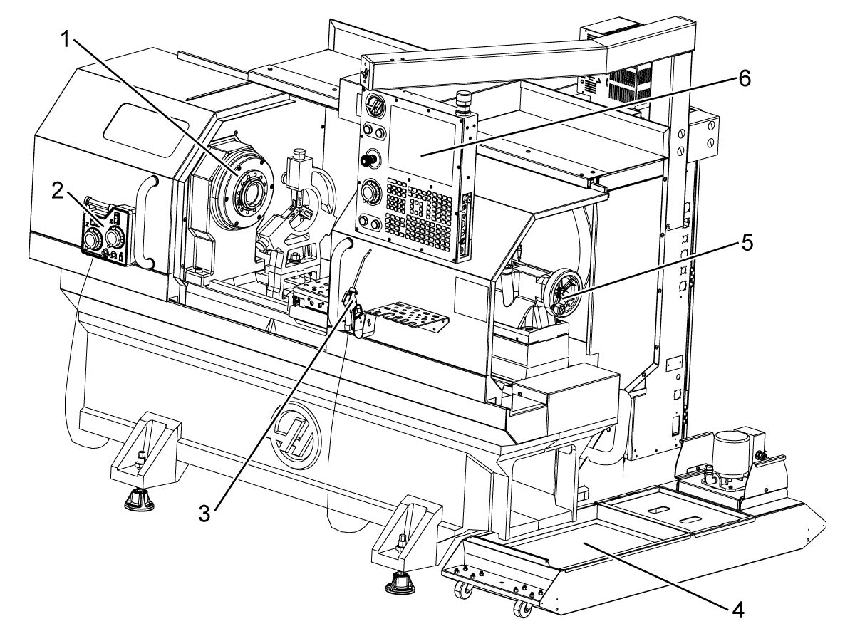
- Элементы токарного станка (вид спереди)
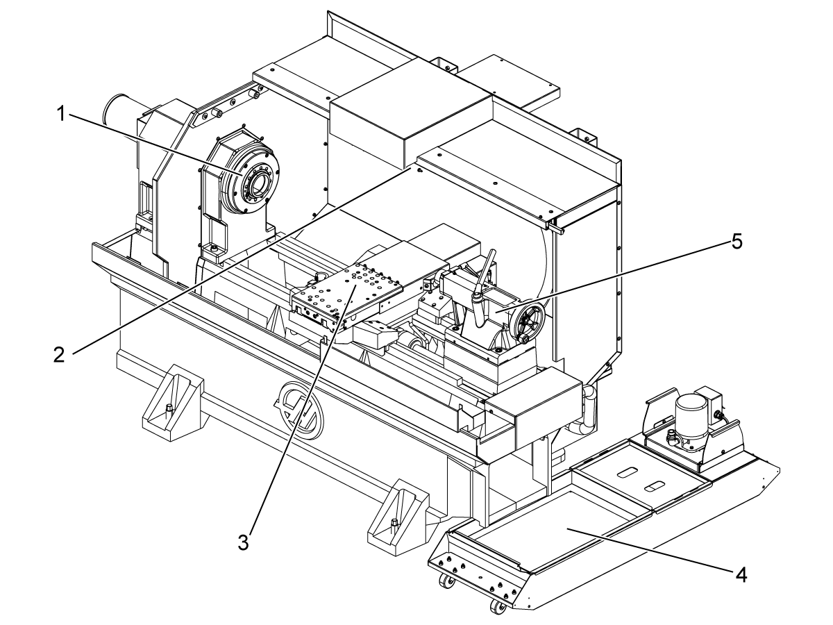
- Элементы токарного станка (вид спереди со снятыми крышками)
- Элементы токарного станка Узел A — подвесной пульт управления со шкафом
- Функции токарного станка, деталь В — Пример панели смазки
- Элементы токарного станка Узел C — узел резервуара СОЖ
- Технические особенности токарного станка Toolroom (вид спереди)
- Технические особенности токарного станка Toolroom (вид спереди, двери сняты)
- Cookies
- What are cookies?
- Цены на доставку Haas
- Свяжитесь с нами
- Результаты поиска
- Web Pages
- Images
- Lathe — Programming
- Базовое программирование
- Подготовка
- Как изготовить деталь на токарном станке Haas
- Включение станка
- Установка инструментальных блоков
- Установка режущего инструмента
- Выставление кулачков
- Ловушка детали
- Подготовка управляющей программы VPS
- Подготовка управляющей программы VPS
- Привязка инструмента
- Привязка детали
Свяжитесь с нами
Результаты поиска
Web Pages
Images
Lathe — Introduction
Краткий обзор
В настоящем руководстве оператора описываются уникальные особенности и функции токарного станка с ЧПУ.
Элементы токарного станка (вид спереди)
Эти рисунки показывают некоторые из стандартных и дополнительных технических особенностей токарного станка Haas. Некоторые из указанных элементов выделены в соответствующих разделах. Имейте в виду, что эти рисунки носят только справочный характер, ваш станок может выглядеть иначе, в зависимости от модели и установленного дополнительного оборудования.
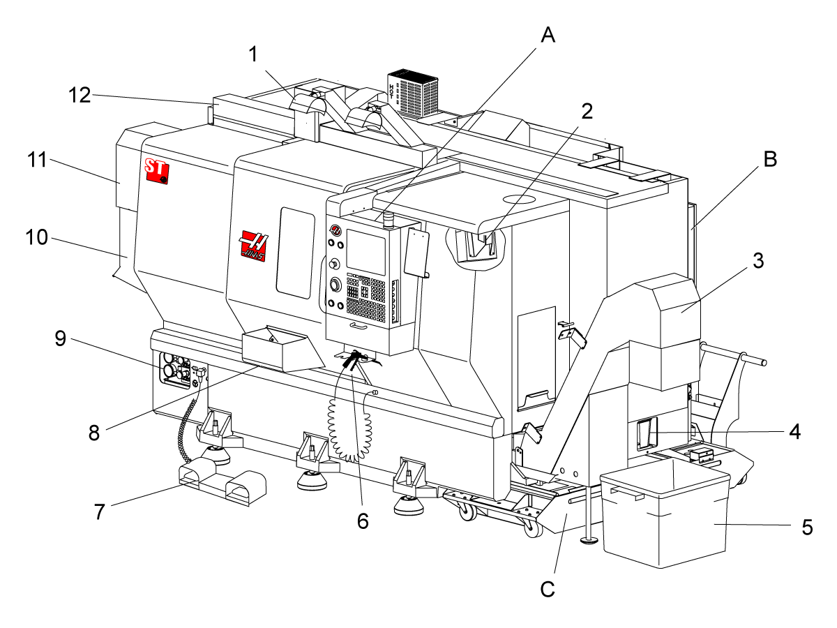
1.) Светильник высокой яркости 2X (опция)
2. Светильник (2X)
3. Транспортер удаления стружки (опция)
=/4 Дренажный контейнер для масла
5. Контейнер для стружки
6. Продувочный пистолет
7. Ножная педаль
8. Ловушка деталей (опция)
9. Гидроагрегат (HPU)
10. Сборник СОЖ
11. Двигатель шпинделя
12. Автоматическая дверь (опция)
A. Подвесной пульт управления
B. Узел панели смазки
C. Резервуар СОЖ
Элементы токарного станка (вид спереди со снятыми крышками)

1.) Двигатель шпинделя
2. Револьверная головка в сборе
3. Задняя бабка (опция)
=/4 Ловушка деталей (опция)
5. Рука ИГТС (опция)
6. Патрон
7. Узел привода оси C (опция)
8. Гидроагрегат (HPU)
9. Узел головки шпинделя
A. Шкаф управления
B. Боковая панель шкафа управления
Элементы токарного станка Узел A — подвесной пульт управления со шкафом
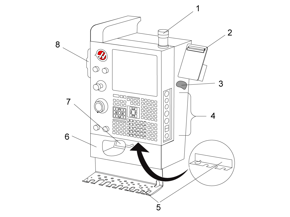
1.) Сигнальный маячок
2. Буфер обмена
3. Руководство оператора и данные по сборочным единицам (хранятся сзади пульта управления)
=/4 Органы управления боковой панели
5. Кронштейн для инструментов (также показан кронштейн для инструментов для тонкого подвесного пульта управления)
6. Бункерный лоток
7. Таблица G- и M-кодов
8. Пульт дистанционного управления
Функции токарного станка, деталь В — Пример панели смазки
1.) Соленоид системы минимальной смазки
2. Воздушный манометр
3. Воздушный предохранительный клапан
=/4 Подача воздуха поворотного стола
5. Сепаратор воздуха/воды
6. Пневматический отсечной клапан
7. Соленоид продувки
8. Патрубок подачи воздуха
9. Резервуар смазки шпинделя
10. Смотровое стекло смазки шпинделя (2)
11. Резервуар смазки оси
12. Манометр смазки
Примечание: Более подробная информация показана на табличках на сервисной дверце.
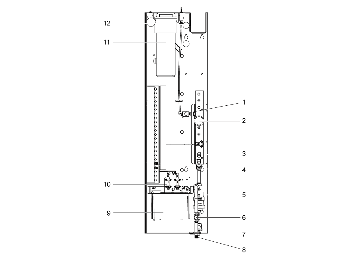
Элементы токарного станка Узел C — узел резервуара СОЖ
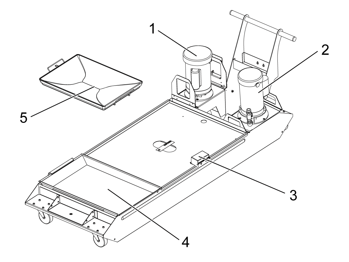
1.) Стандартный насос подачи СОЖ
2. Насос подачи СОЖ высокого давления (опция)
3. Датчик уровня СОЖ
=/4 Сетчатый фильтр для стружки
5. Фильтрующая сетка
Технические особенности токарного станка Toolroom (вид спереди)
1.) Узел шпинделя
2. Электронный маховичок
3. Продувочный пистолет
=/4 Резервуар для СОЖ
5. Задняя бабка
6. Подвесной пульт управления
Технические особенности токарного станка Toolroom (вид спереди, двери сняты)
1.) Торец шпинделя
2. Освещение рабочей зоны
3. Поперечные салазки (резцедержатель / револьверная головка не показана)
=/4 Резервуар для СОЖ
5. Задняя бабка

Cookies
To make this site work properly, we sometimes place small data files called cookies on your device. Most big websites do this too.
What are cookies?
A cookie is a small text file that a website saves on your computer or mobile device when you visit the site. It enables the website to remember your actions and preferences (such as login, language, font size and other display preferences) over a period of time, so you don’t have to keep re-entering them whenever you come back to the site or browse from one page to another.
美元价格不包括关税、报关费用、保险费、增值税及运费。
USD prices DO NOT include customs duty, customs fees, insurance, VAT, or freight.
人民币价格包含关税、报关费用、货运保险和增值税, 但不包括运费。
CNY prices include customs duty, customs fees, insurance, and VAT. DOES NOT include freight.
Цены на доставку Haas
Эта цена включает стоимость доставки, экспортные и импортные пошлины, страхование и любые другие расходы, понесенные во время доставки в место во Франции, согласованные с вами в качестве покупателя. Никакие другие обязательные расходы не могут быть добавлены к поставке продукта Haas CNC.
ДЛЯ ПОЛУЧЕНИЯ ПОДРОБНОЙ ИНФОРМАЦИИ НАЖМИТЕ ЗДЕСЬ
ПОЛУЧАЙТЕ ЛУЧШИЕ СОВЕТЫ ОТ HAAS И УЗНАВАЙТЕ О ПОСЛЕДНИХ РАЗРАБОТКАХ В ОБЛАСТИ ТЕХНОЛОГИЙ…
Источник
Свяжитесь с нами
Результаты поиска
Web Pages
Images
Lathe — Programming
Базовое программирование
Типичная программа ЧПУ имеет (3) части:
1) Подготовка: Эта часть программы выбирает коррекцию детали и коррекцию на инструмент, выбирает режущий инструмент, включает подачу СОЖ, задает скорость вращения шпинделя и выбирает абсолютное или относительное позиционирование для перемещения оси.
2) Резание: Эта часть программы определяет траекторию инструмента и скорость подачи для операции резания.
3) Завершение: Эта часть программы перемещает шпиндель в сторону, выключает шпиндель, выключает СОЖ и перемещает стол в положение, в котором деталь можно выгрузить и осмотреть.
Это базовая программа, которая выполняет рез глубиной 0.100″ (2.54 мм) инструментом 1 в обрабатываемой детали по прямолинейной траектории от X=0.0, Y=0.0 до X=4.0, Y=4.0.
ПРИМЕЧАНИЕ. Блок программы может содержать больше одного кода G, если эти коды G из различных групп. Разместить два кода G из одной группы в одном блоке программы невозможно. Кроме того, имейте в виду, что в блоке допускается только один код M.
%
O40001 (Базовая программа) ;
(G54 X0 Y0 — верхний правый угол детали) ;
(Z0 — сверху на детали) ;
(T1 — концевая фреза 1/2″) ;
(НАЧАЛО БЛОКОВ ПОДГОТОВКИ) ;
T1 M06 (Выбор инструмента 1) ;
G00 G90 G17 G40 G49 G54 (Безопасный запуск) ;
X0 Y0 (Ускоренное перемещение в 1-е положение) ;
S1000 M03 (Шпиндель вращается по часовой стрелке) ;
G43 H01 Z0.1 (Коррекция на инструмент 1 вкл.) ;
M08 (включить подачу СОЖ) ;
(НАЧАЛО РЕЖУЩИХ БЛОКОВ) ;
G01 F20. Z-0.1 (Подача на глубину резания) ;
X-4. Y-4. (линейное перемещение) ;
(НАЧАТЬ БЛОКИ ЗАВЕРШЕНИЯ) ;
G00 Z0.1 M09 (Ускоренное перемещение отвода, выключение подачи СОЖ) ;
G53 G49 Z0 M05 (Исходное положение Z, выключение шпинделя) ;
G53 Y0 (исходное положение Y) ;
M30 (Завершение программы) ;
%
Подготовка
Далее следуют подготовительные блоки текста типовой программы O40001:
выбирает инструмент, коррекцию 1 и подает команду на смену инструмента на инструмент 1.
Называется «строка безопасного запуска». Хорошей практикой обработки является вставка в программы этого блока текста программы после каждой смены инструмента. G00 определяет последующее перемещение оси как выполняющееся в режиме ускоренного перемещения. G18 определяет плоскость резания как плоскость XZ. G20 определяет координаты позиционирования в дюймах. G40 отменяет коррекцию на инструмент. G80 отменяет все стандартные циклы. G99 переводит станок в режим подачи на оборот.
G97 отменяет постоянную скорость резания (CSS), что делает значение S прямой скоростью вращения в 500 об/мин. S500 – это адрес скорости вращения шпинделя. С помощью адресного кода Snnnn, где nnnn – это значение необходимой скорости вращения шпинделя. M03 включает шпиндель.
Примечание: На токарных станках с редуктором система управления не будет выбирать высшую передачу или низшую передачу за вас. Вы должны использовать M41 (низшая передача) или M42 (высшая передача) в строке перед кодом. См. M41 / M42 Принудительное включение низшей / высшей передачи, где имеется дальнейшая информация об этих кодах M.
Источник
Как изготовить деталь на токарном станке Haas
Мы рассказываем, как подготовить станок и управляющую программу, как установить инструмент, выставить кулачки, подготовить ловушку деталей, привязать инструмент.
| Подготовительный блок текста программы | Описание |
| % | Обозначает начало программы, написанной в текстовом редакторе. |
| O40001 (Базовая программа) ; | O40001 – это имя программы. Соглашение об именах программ следует формату Onnnnn: Буква «O» или «o» и число из 5 цифр. |
| (G54 X0 — в центре вращения) ; | Комментарий |
| (Z0 — на торце детали) ; | Комментарий |
| (T1 — это торцевой резец) ; | Комментарий |
| T101 (Выбор инструмента и коррекции 1) ; | T101 |
| G00 G18 G20 G40 G80 G99 (Безопасный запуск) ; | |
| G50 S1000 (Ограничение скорости вращения шпинделя 1000 об/мин) ; | G50 ограничивает максимальную скорость вращения шпинделя 1000 об/мин. S1000 – это адрес скорости вращения шпинделя. С помощью адресного кода Snnnn, где nnnn – это значение необходимой скорости вращения шпинделя. |
| G97 S500 M03 (Постоянная скорость резания выключена, шпиндель вращается по часовой стрелке) ; |
| 00:00 | Вступление |
| 00:38 | Включение станка |
| 01:07 | Установка инструментальных блоков |
| 01:56 | Установка режущего инструмента |
| 02:20 | Выставление кулачков |
| 03:45 | Ловушка детали |
| 04:10 | Подготовка управляющей программы VPS |
| 05:40 | Разбор программы в графическом режиме |
| 09:58 | Привязка инструмента |
| 11:20 | Привязка детали |
| 12:25 | Обработка |
| 13:52 | Заключение |
Сегодня мы расскажем, как подготовить станок и управляющую программу. Покажем всё: от самого начала до готовой детали.
Вся демонстрация будет производиться на станке Haas ST-10. Для нашей программы нам понадобится 3 резца: резьбонарезной, проходной и отрезной. Также мы будем использовать сверло и радиальную приводную станцию со сверлом меньшего диаметра. Станок укомплектован револьвером VDI, также имеется опция дополнительной оси C и приводного инструмента.
Включение станка
Включаем станок. После завершения загрузки на экран выведется список действий, которые нужно выполнить. Отжимаем грибок, нажимаем кнопку POWER UP. У нас будет 3 варианта выхода в ноль: 1) вывести револьвер в ноль; 2) вывести в ноль все оси по порядку; 3) сделать это все в ручном режиме.
Установка инструментальных блоков
Если мы выберем вариант со всеми осями, то сперва станок выведет ось X в 0, затем Z, а потом обнулит револьвер. Теперь можно повернуть револьвер в нужное положение, чтобы поменять инструмент. Для этого перейдем в MDI, введём одиннадцатый номер инструмента и нажмем кнопку вращения револьвера в обратную сторону. Удаляем пластиковую заглушку, ослабляем крепежный винт. После этого можно ставить базовый блок, совместив бобышку с отверстием. Закручиваем винт, а затем хорошенько его затягиваем. Аналогичным образом поворачиваем револьвер в следующие необходимое положение, устанавливаем блок и затягиваем так, чтобы он прижался к револьверу. Точно также устанавливается и приводная станция. Правильная компоновка блоков позволяет избежать столкновений во время обработки.
Установка режущего инструмента
Установим проходной резец, резьбонарезной и отрезной. Установим сверло в цанговом патроне и затягиваем ключом. Также устанавливаем и затягиваем сверло в приводной станции.
Выставление кулачков
В качестве заготовки — ободранный круг из конструкционной стали (диаметр 45,1 мм). Раскрытие кулачков не позволяет установить заготовку. О том как расточить кулачки смотрите Работа с мягкими кулачками на токарном станке Haas. Если кулачки не растачивать, то пятно контакта будет меньше. Это вынудит занизить режимы резания.
Для удобства откручивания кулачков перейдем в режим текущие команды и включим тормоз шпинделя. Шпиндель будет заблокирован, и можно будет легко открутить все винты. Раздвигаем кулачки для того, чтобы извлечь заглушку. Достаем заглушку из тяговой трубы для того, чтобы вставить заготовку. Выставляем кулачки на нужный нам диаметр. По гребенке убедитесь, что все кулачки на одном расстоянии от центра. После этого можно затянуть все винты и убедиться, что заготовка зажимается как надо.
Ловушка детали
В конце обработки детали мы ее отрежем, а значит нам потребуется ловитель. Для того, чтобы его выдвинуть, переходим во вкладку текущие команды и нажимаем F2. Высота подъема ловителя регулируются винтом. Нажатием кнопки F2 задвигаем ловитель обратно.
Подготовка управляющей программы VPS
О том как создать новую программу загрузить ее с USB или сетевого диска смотрите в Как создавать и редактировать программы (ЧПУ Haas NGC). На этот раз программа была написана полностью на стойке. Разберем ее чуть позже, а сейчас более подробно остановимся на визуальном программировании.
Выберем вкладку приводного инструмента и радиальное сверление. В первых 2 строчках мы выбираем номер инструмента и номер привязки, а в следующей строке — номер привязки деталей. В 4 строке отключаем подачу СОЖ и вводим диаметр детали в месте сверления 20 мм; расстояние по осям, на которое станок подойдет к заготовке на ускоренной подаче оставляем 5 мм; обороты сверла выставляем на 3000; выбираем сверление нескольких отверстий и выставляем начальный угол. Нам требуется просверлить 4 отверстия на расстоянии 7 мм от нуля заготовки. Расстояние, на которое станок будет выводить сверло, оставим без изменений, а глубину сверления зададим 8 мм. Минутную подачу оставляем 160 и оставляем отведение инструмента по осям X и Z. Созданный нами блок закончится опциональной остановкой.
Теперь остается просто все загрузить в буфер обмена и вставить в нужное место. Станок позаботился о безопасности и написал строки, предназначены для того, чтобы уберечь от аварий. Для наших программы они не нужны, поэтому удалим их.
О том как редактировать программу прямо на стойке см. Как создавать и редактировать программы (ЧПУ Haas NGC).
Подготовка управляющей программы VPS
Давайте воспользуемся графическим режимом и подробнее рассмотрим программу. Нажимаем CYCLE START, нажимаем F2 для увеличения, чтобы рассмотреть подробнее детали. Кнопками PAGE UP и PAGE DOWN выбираем необходимый масштаб. Затем с помощью стрелок наводим рамку на деталь. После масштабирования графический экран очиститься и нужно будет нарисовать все заново. Но на этот раз будем использовать single-блок для выполнения программы построчно.
В начале программы выбираем 11-й инструмент с 11-м корректором и подъезжаем ускорено в точку Z5 в системе координат детали G54. Затем приближаемся к детали по оси X, а потом — по оси Z. После этого сжимаем кулачки и ставим программу на паузу. Пока программа остановлена открываем дверь. На станках с автоматической дверью это можно сделать при помощи команды M85. Выдвигаем заготовку до упора и сжимаем кулачки при помощи педали. После этого нажимаем CYCLE START и продолжаем программу.
Отводим инструмент от детали по оси Z, а затем в точку X0 в системе координат станка. Затем делаем опциональную остановку.
Переходим непосредственно к обработке детали. Сперва обработаем торец. Ограничим обороты шпинделя двумя тысячами оборотов; установим постоянную скорость резания на 200 м/мин; вращение шпинделя — вперед. Ускорено подъезжаем к детали, включаем СОЖ, запускаем цикл обтачивания торцов до координаты Z0 с подачей 18 соток на оборот. Ускорено отводим инструмент от заготовки и начинаем цикл снятия припуска.
P — это номер начального блока траектории чернового прохода; Q — номер конечного блока; D — глубина реза для каждого прохода; F — скорость подачи; U — величина и направление припуска на чистовую обработку по оси X (W — по оси Z).
Для чистового прохода увеличим скорость резания с 200 до 220 м/мин, запустим цикл чистовой обработки по той же самой траектории с 5-го по 6-ой блок, но на этот раз с подачей 18 соток на оборот. Отводим инструмент, отключаем СОЖ, уходим в машинный ноль и делаем опциональную остановку.
Приступаем к нарезанию резьбы. Выбираем первый инструмент с первым корректором, ограничиваем скорость вращения шпинделя до 600 об/мин, отключаем постоянную скорость резания и вращения шпинделя вперед. Ускорено приближаемся к заготовке, включаем СОЖ, активируем фаску выхода из резьбы и вызываем нарезание резьбы в несколько проходов.
X — это внутренний диаметр резьбы; Z — точка, в которой резьба заканчивается; D — глубина первого прохода; K — высота профиля резьбы; F — подача.
Можно конечно отключить single-блок, но мы жмем каждый проход вручную. Главное — терпение.
Вот в принципе и всё. Отключаем фаску на выходе из резьбы, отводим инструмент, отключаем СОЖ, отводим станок в ноль и делаем опциональную остановку. Проходным резцом убираем заусенец с первого витка и делаем чистовой проход резьбонарезным резцом. Теперь возьмём сверло 8,5 мм и запустим стандартный цикл сверления с периодическим выводом инструмента.
Z — это координата дна отверстия; R — положение плоскости вывода инструмента; Q — период вывода; F — подача.
Для радиального сверления нужно включить минутную подачу, включить обороты приводного инструменты на 3000 об/мин и запустить стандартный цикл радиального сверления.
R — это координата плоскости; X — координата дна отверстия; Z — смещение отверстия от нуля; F — подача.
Изначально угол оси C был 0°, угол между отверстиями — 90°. Отменяем стандартный цикл, возвращаем подачи на оборот, выключаем инструмент, уводим станок в ноль и отключаем тормоз шпинделя. Берем наш последний инструмент (канавочный резец), формируем шляпку, выдвигаем ловушку деталей и отрезаем готовую деталь. Уводим ловушку и станок в ноль, заканчиваем программу.
Привязка инструмента
Выдвинем щуп привязки, проверим номер инструмента и тип установленной пластины. Теперь нужно выбрать ось и вручную подвести инструмент на расстоянии 6 мм от щупа. Сперва подводим по Z, а затем по X. Вся необходимая подготовка выполнена. Остается сгенерировать код, нажатием клавиши F4, и выгрузить всё в MDI.
Запускаем выполнение программы кнопкой CYCLE START. Результаты привязки автоматические перенеслись в таблицу. Отводим инструмент от щупа, возвращаем станок в ноль и выбираем следующий инструмент. Подводим вручную новый инструмент к щупу. Заново генерируем код в MDI с новым инструментом и запускаем цикл привязки. Так нужно будет повторить с каждым инструментом.
Привязка детали
Вставляем заготовку в патрон, выставляем нужный вылет и вручную подводим привязанный инструмент до касания. Сохраняем эту точку в таблице привязок и отводим инструмент. Задвигаем заготовку в патрон, чтобы можно было начать программу и подвести упор. Выдвигаем заготовку до базового блока и зажимаем с педали. Теперь проверяем, что вылет заготовки соответствуют нашим ожиданиям.
Мы уже почти готовы к обработке детали, но нужно проверить еще один момент. Подводим инструмент к заготовке, замеряем расстояние и сверяем с тем, что у нас на экране. Если все совпало, то можно резать.
Источник