- Manuals
- Brands
- ASROCK Manuals
- Motherboard
- H81M
- User manual
-
Contents
-
Table of Contents
-
Bookmarks
Quick Links
Related Manuals for ASROCK H81M
Summary of Contents for ASROCK H81M
-
Page 1
User Manual… -
Page 2: Copyright Notice
(including damages for loss of profits, loss of business, loss of data, interruption of business and the like), even if ASRock has been advised of the possibility of such damages arising from any defect or error in the documentation or product.
-
Page 3: Table Of Contents
Contents Chapter 1 Introduction Package Contents Specifications Unique Features Motherboard Layout I/O Panel Chapter 2 Installation Installing the CPU Installing the CPU Fan and Heatsink Installing Memory Modules (DIMM) Expansion Slots (PCI and PCI Express Slots) Jumpers Setup Onboard Headers and Connectors CrossFireX and Quad CrossFireX Operation Guide…
-
Page 4
Start8 Chapter 4 UEFI SETUP UTILITY Introduction 4.1.1 UEFI Menu Bar 4.1.2 Navigation Keys Main Screen OC Tweaker Screen Advanced Screen 4.4.1 CPU Configuration 4.4.2 Chipset Configuration 4.4.3 Storage Configuration 4.4.4 Intel® Smart Connect Technology 4.4.5 Super IO Configuration 4.4.6 ACPI Configuration 4.4.7 USB Configuration 4.4.8 Trusted Computing Tools… -
Page 5: Chapter 1 Introduction
ASRock’s website without further notice. If you require technical support related to this motherboard, please visit our website for specific information about the model you are using. You may find the latest VGA cards and CPU support list on ASRock’s website as well. ASRock website http://www.asrock.com.
-
Page 6: Specifications
1.2 Specifications Platform • Micro ATX Form Factor • All Solid Capacitor design • Supports 4 Generation Intel® Core i7 / i5 / i3 / Xeon® / Pentium® / Celeron® in LGA1150 Package • 4 Power Phase Design • Supports Intel® Turbo Boost 2.0 Technology Chipset • Intel®…
-
Page 7
H81M • Supports DVI-D with max. resolution up to 1920×1200 @ 60Hz • Supports D-Sub with max. resolution up to 1920×1200 @ 60Hz • Supports Auto Lip Sync, Deep Color (12bpc), xvYCC and HBR (High Bit Rate Audio) with HDMI (Compliant HDMI monitor is required) • Supports HDCP function with DVI-D and HDMI ports… -
Page 8
Storage • 2 x SATA3 6.0 Gb/s connectors, support NCQ, AHCI and “Hot Plug” functions • 2 x SATA2 3.0 Gb/s connectors, support NCQ, AHCI and “Hot Plug” functions Connector • 1 x IR header • 1 x Print Port header • 1 x COM port header • 1 x Chassis Intrusion header • 1 x TPM header… -
Page 9
Due to limitation, the actual memory size may be less than 4GB for the reservation for system usage under Windows® 32-bit operating systems. Windows® 64-bit operat- ing systems do not have such limitations. You can use ASRock XFast RAM to utilize the memory that Windows® cannot use. -
Page 10: Unique Features
LED, FAN-Tastic Tuning, OC Tweaker and a whole lot more. ASRock Instant Flash ASRock Instant Flash is a BIOS flash utility embedded in Flash ROM. This conve- nient BIOS update tool allows you to update the system BIOS in a few clicks without preparing an additional floppy diskette or other complicated flash utility.
-
Page 11
And it also boosts the speed of Adobe Photoshop 5 times faster. Another advantage of ASRock XFast RAM is that it reduces the frequency of accessing your SSDs or HDDs in order to extend their lifespan. -
Page 12
Windows® 8 brings the ultimate boot up experience. The lightning boot up speed makes it hard to access the UEFI setup. ASRock Restart to UEFI allows users to enter the UEFI automatically when turning on the PC. By enabling this function, the PC will enter the UEFI directly after you restart. -
Page 13
ASRock FAN-Tastic Tuning ASRock FAN-Tastic Tuning is included in A-Tuning. Configure up to five different fan speeds using the graph. The fans will automatically shift to the next speed level when the assigned temperature is met. -
Page 14: Motherboard Layout
CPU_FAN2 CPU_FAN1 CMOS Battery ATX12V1 USB 2.0 T: USB4 B: USB5 USB 3.0 Top: T: USB0 RJ-45 B: USB1 CHA_FAN2 SPDIF1_OUT1 H81M HD_AUDIO1 PCIE1 Audio CODEC PCI1 Intel RoHS Fast RAM PCI2 CLRCMOS1 Fast USB Fast LAN PCIE2 32Mb BIOS…
-
Page 15
H81M No. Description ATX 12V Power Connector (ATX12V1) CPU Fan Connector (CPU_FAN1) CPU Fan Connector (CPU_FAN2) Power Fan Connector (PWR_FAN1) 2 x 240-pin DDR3 DIMM Slots (DDR3_A1, DDR3_A2) ATX Power Connector (ATXPWR1) SATA2 Connector (SATA_5) SATA2 Connector (SATA_4) SATA3 Connector (SATA_0) SATA3 Connector (SATA_1) USB 3.0 Header (USB3_2_3) -
Page 16: I/O Panel
1.5 I/O Panel No. Description No. Description USB 2.0 Ports (USB01) Microphone (Pink) D-Sub Port Optical SPDIF Out Port LAN RJ-45 Port* USB 3.0 Ports (USB3_01) Central / Bass (Orange) USB 2.0 Ports (USB45) Rear Speaker (Black) HDMI Port Line In (Light Blue) DVI-D Port Front Speaker (Lime)** PS/2 Keyboard Port…
-
Page 17
H81M * There are two LEDs on each LAN port. Please refer to the table below for the LAN port LED indications. ACT/LINK LED SPEED LED LAN Port Activity / Link LED Speed LED Status Description Status Description No Link… -
Page 18: Chapter 2 Installation
Chapter 2 Installation This is a Micro ATX form factor motherboard. Before you install the motherboard, study the configuration of your chassis to ensure that the motherboard fits into it. Pre-installation Precautions Take note of the following precautions before you install motherboard components or change any motherboard settings.
-
Page 19: Installing The Cpu
H81M 2.1 Installing the CPU 1. Before you insert the 1150-Pin CPU into the socket, please check if the PnP cap is on the socket, if the CPU surface is unclean, or if there are any bent pins in the socket.
-
Page 21
H81M Please save and replace the cover if the processor is removed. The cover must be placed if you wish to return the motherboard for after service. -
Page 22: Installing The Cpu Fan And Heatsink
2.2 Installing the CPU Fan and Heatsink…
-
Page 23: Installing Memory Modules (Dimm)
H81M 2.3 Installing Memory Modules (DIMM) This motherboard provides two 240-pin DDR3 (Double Data Rate 3) DIMM slots, and supports Dual Channel Memory Technology. 1. For dual channel configuration, you always need to install identical (the same brand, speed, size and chip-type) DDR3 DIMM pairs.
-
Page 25: Expansion Slots (Pci And Pci Express Slots)
H81M 2.4 Expansion Slots (PCI and PCI Express Slots) There are 2 PCI slots and 2 PCI Express slots on the motherboard. Before installing an expansion card, please make sure that the power supply is switched off or the power cord is unplugged. Please read the documentation of the expansion card and make necessary hardware settings for the card before you start the installation.
-
Page 26: Jumpers Setup
2.5 Jumpers Setup The illustration shows how jumpers are setup. When the jumper cap is placed on the pins, the jumper is “Short”. If no jumper cap is placed on the pins, the jumper is “Open”. The illustration shows a 3-pin jumper whose pin1 and pin2 are “Short” when a jumper cap is placed on these 2 pins.
-
Page 27: Onboard Headers And Connectors
H81M 2.6 Onboard Headers and Connectors Onboard headers and connectors are NOT jumpers. Do NOT place jumper caps over these headers and connectors. Placing jumper caps over the headers and connectors will cause permanent damage to the motherboard. System Panel Header…
-
Page 28
Serial ATA2 Connectors These two SATA2 (SATA_4: connectors support SATA see p.10, No. data cables for internal (SATA_5: storage devices with up to see p.10, No. 7) 3.0 Gb/s data transfer rate. Serial ATA3 Connectors These two SATA3 (SATA_0: connectors support SATA see p.10, No.
 -
Page 29
H81M 1. High Definition Audio supports Jack Sensing, but the panel wire on the chassis must support HDA to function correctly. Please follow the instructions in our manual and chassis manual to install your system. 2. If you use an AC’97 audio panel, please install it to the front panel audio header by the steps below: A. -
Page 30
CPU Fan Connectors This motherboard pro- (4-pin CPU_FAN1) vides a 4-Pin CPU fan +12V (see p.10, No. 2) CPU_FAN_SPEED (Quiet Fan) connector. FAN_SPEED_CONTROL If you plan to connect a (3-pin CPU_FAN2) 3-Pin CPU fan, please (see p.10, No. 3) connect it to Pin 1-3. +12V FAN_SPEED ATX Power Connector… -
Page 31
H81M Chassis Intrusion Header This motherboard (2-pin CI1) supports CASE OPEN Signal (see p.10, No. 22) detection feature that detects if the chassis cove has been removed. This feature requires a chassis with chassis intrusion detection design. TPM Header This connector supports… -
Page 32: Crossfirex Tm And Quad Crossfirex Tm Operation Guide
2.7 CrossFireX and Quad CrossFireX Operation Guide This motherboard supports CrossFireX and Quad CrossFireX that allows you to install up to two identical PCI Express x16 graphics cards. Currently CrossFireX ® and Quad CrossFireX are supported with Windows 7 / 7 64-bit / 8 / 8 64-bit OS. 1.
-
Page 33
H81M Step 3 Connect a VGA cable or a DVI cable to the monitor connector or the DVI connec- tor of the graphics card that is inserted to PCIE1 slot. -
Page 34: Driver Installation And Setup
2.7.2 Driver Installation and Setup Step 1 Power on your computer and boot into OS. Step 2 Remove the AMD drivers if you have any VGA drivers installed in your system. The Catalyst Uninstaller is an optional download. We recommend using this utility to uninstall any previously installed Catalyst drivers prior to installation.
-
Page 35: Chapter 3 Software And Utilities Operation
H81M Chapter 3 Software and Utilities Operation 3.1 Installing Drivers The Support CD that comes with the motherboard contains necessary drivers and useful utilities that enhance the motherboard’s features. Running The Support CD To begin using the support CD, insert the CD into your CD-ROM drive. The CD automatically displays the Main Menu if “AUTORUN”…
-
Page 36: A-Tuning
3.2 A-Tuning A-Tuning is ASRock’s multi purpose software suite with a new interface, more new features and improved utilities, including XFast RAM, Dehumidifier, Good Night LED, FAN-Tastic Tuning, OC Tweaker and a whole lot more. 3.2.1 Installing A-Tuning When you install the all-in-one driver to your system from ASRock’s support CD, A-Tuning will be auto-installed as well.
-
Page 37
H81M Tools Various tools and utilities. XFast RAM Boost the system’s performance and extend the HDD’s or SDD’s lifespan! Create a hidden partition, then assign which files should be stored in the RAM drive. Fast Boot Fast Boot minimizes your computer’s boot time. Please note that Ultra Fast mode is only supported by Windows 8 and the VBIOS must support UEFI GOP if you are using an external graphics card. -
Page 38
Dehumidifier Prevent motherboard damages due to dampness. Enable this function and configure the period of time until the computer powers on, and the duration of the dehumidifying process. OC Tweaker Configurations for overclocking the system. System Info View information about the system. -
Page 39
H81M Tech Service Contact Tech Service. -
Page 40: Intel® Smart Connect Technology
3.3 Intel® Smart Connect Technology Intel® Smart Connect Technology is a feature that periodically wakes your computer from Windows® sleep state to refresh email or social networking applications. It saves your waiting time and keeps the content always up-to-date. 3.3.1 System Requirements •…
-
Page 41: Setup Guide
3.3.2 Setup Guide Installing ASRock Smart Connect Utility Step 1 Install ASRock Smart Connect Utility, which is located in the folder at the following path of the Support CD: \ ASRock Utility > Smart Connect. Step 2 Once installed, run ASRock Smart Connect from your desktop or go to Windows…
-
Page 42
Step 3 Click the Add button. Take Foxmail as an example, add Foxmail to the Application list. Step 4 Select Foxmail from the Application List, then click the arrow pointing right to add this application to the Smart Connect List. Step 5 Click Apply to enable Smart Connect. -
Page 43
H81M Step 6 Double-click the Intel® Smart Connect Technology Manager icon in the Windows system tray. Step 7 Drag the slider to configure how often the system will connect to the network to download updates. Shorter durations will provide more frequent updates, but may cause more power consumption. -
Page 44
The system will wake up from sleep state periodically, and then start to update Foxmail. The screen will not display anything so the computer can maintain minimum power usage. Afterwards, the system will automatically return to sleep state again. Upon waking up the system, you will find the new mail that were sent to you during sleep state are already updated and ready to be read in Foxmail. -
Page 45: Qualcomm® Atheros® Security Wake On Internet Technology
H81M 3.4 Qualcomm® Atheros® Security Wake On Internet Technology Qualcomm® Atheros® Security Wake On Internet Technology allows you to wake up and remote control your home computer from energy efficient sleep mode. Before configuring this feature, make sure that the «PCI Device Power On» is enabled in UEFI SETUP UTILITY >…
-
Page 46
Step 3 Click on Remote Client and follow the onscreen instruction to complete the installation. Step 4 Double-click the Sunlogin Remote Control icon in the Windows system tray. Step 5 Make sure that «Remote wakeup module» and «Remote control module» is set to On. -
Page 47
H81M Installing Sunlogin control client Step 1 For Windows users: Download «Control Client» from the Download section of sunlogin.oray.com and execute it. Log-in with your Sunlogin Account and Password For iPad/iPhone users: Download “Sunlogin” from App Store and install the app. Then fill in your Sunlogin… -
Page 48
For Andriod mobile device users: Search “Sunlogin” in Google PLAY and then install the app. Then fill in your Sunlogin Account and Password. Using Remote Wakeup For Windows users: Select one Host (Offline with Gray power button) on the control client panel to wake up your home computer. -
Page 49
H81M For Andriod mobile device users: Tap one Host (Offline with Blue power button ) on the Host List. Then tap the Power button to wakeup your home computer. -
Page 50
Using Remote Control For Windows users: Right-click on a Host (Online with Blue Windows logo) on the control client panel. Then key in your remote access password. For iPad/iPhone users: Tap one online machine on the Host List and fill in the Access password to start using remote control. -
Page 51
H81M For Andriod mobile device users: Tap one online machine and fill in the Access password to start using remote control. Tutorial Video… -
Page 52: Start8
3.5.1 Installing Start8 Install Start8, which is located in the folder at the following path of the Support CD: \ ASRock Utility > Start8. 3.5.2 Configuring Start8 Style Select between the Windows 7 style and Windows 8 style Start Menu. Then select…
-
Page 53
H81M Configure Configure provides configuration options, including icon sizes, which shortcuts you want Start Menu to display, quick access to recently used apps, the functionality of the power button, and more. Control… -
Page 54
Control lets you configure what a click on the start button or a press on the Windows key does. Desktop Desktop allows you to disable the hot corners when you are working on the desktop. It also lets you choose whether or not the system boots directly into desktop mode and bypass the Metro user interface. -
Page 55: Chapter 4 Uefi Setup Utility
Chapter 4 UEFI SETUP UTILITY 4.1 Introduction ASRock Interactive UEFI is a blend of system configuration tools, cool sound effects and stunning visuals. Not only will it make BIOS setup less difficult but also a lot more amusing. This section explains how to use the UEFI SETUP UTILITY to configure your system.
-
Page 56: Navigation Keys
4.1.2 Navigation Keys Use < > key or < > key to choose among the selections on the menu bar, and use < > key or < > key to move the cursor up or down to select items, then press <Enter>…
-
Page 57: Main Screen
When you enter the UEFI SETUP UTILITY, the Main screen will appear and display the system overview. Active Page on Entry Select the default page when entering the UEFI setup utility. UEFI Guide UEFI Guide is a quick tutorial for ASRock’s UEFI setup Utility. You may abort the tutorial by pressing «esc».
-
Page 58: Oc Tweaker Screen
4.3 OC Tweaker Screen In the OC Tweaker screen, you can set up overclocking features. Because the UEFI software is constantly being updated, the following UEFI setup screens and descriptions are for reference purpose only, and they may not exactly match what you see on your screen.
-
Page 59: Long Duration Maintained
H81M Filter PLL Frequency CPU BCLK Filter Frequency. Choose 1.6 for better overclocking capabilities. Long Duration Power Limit Configure Package Power Limit 1 in watts. When the limit is exceeded, the CPU ratio will be lowered after a period of time. A lower limit can protect the CPU and save power, while a higher limit may improve performance.
-
Page 60: Dram Frequency
Load XMP Setting Load XMP settings to overclock the DDR3 memory and perform beyond standard specifications. DRAM Reference Clock Select Auto for optimized settings. DRAM Frequency If [Auto] is selected, the motherboard will detect the memory module(s) inserted and assign the appropriate frequency automatically. DRAM Configuration DRAM Tweaker Fine tune the DRAM settings by leaving marks in checkboxes.
-
Page 61
H81M accessing columns within it. Row Precharge Time (tRP) The number of clock cycles required between the issuing of the precharge command and opening the next row. RAS# Active Time (tRAS) The number of clock cycles required between a bank active command and issuing the precharge command. -
Page 62
tREFI Configure refresh cycles at an average periodic interval. tCKE Configure the period of time the DDR3 initiates a minimum of one refresh command internally once it enters Self-Refresh mode. tRDRD Configure between module read to read delay. tRDRDDR Configure between module read to read delay from different ranks. tRDRDDD Use this to change DRAM tRWSR Auto/Manual settings. -
Page 63
H81M tRDWRDD Configure between module read to write delay from different DIMMs. RTL (CHA) Configure round trip latency for channel A. RTL (CHB) Configure round trip latency for channel B. IO-L (CHA) Configure IO latency for channel A. IO-L (CHB) Configure IO latency for channel B. -
Page 64
FIVR Switch Frequency Offset Configure the percentage of frequency boost or deduction. CPU Voltage Mode Auto: For optimized settings. Adaptive: Add voltage to the CPU when the system is under heavy load. Override: The voltage is fixed. CPU Override Voltage Configure the voltage added to the CPU when the system is under heavy load. -
Page 65: Voltage Configuration
H81M Voltage Configuration DRAM Voltage Use this to configure DRAM Voltage. The default value is [Auto]. PCH 1.05V Voltage Chipset 1.05V Voltage. Use default settings for best performance. PCH 1.5V Voltage I/O 1.5V Voltage. Use default settings for best performance.
-
Page 66: Advanced Screen
4.4 Advanced Screen In this section, you may set the configurations for the following items: CPU Con- figuration, Chipset Configuration, Storage Configuration, Intel® Smart Connect Technology, Super IO Configuration, ACPI Configuration, USB Configuration and Trusted Computing. Setting wrong values in this section may cause the system to malfunction.
-
Page 67: Cpu Configuration
H81M 4.4.1 CPU Configuration Intel Hyper Threading Technology Intel Hyper Threading Technology allows multiple threads to run on each core, so that the overall performance on threaded software is improved. Active Processor Cores Select the number of cores to enable in each processor package.
-
Page 68: Intel Virtualization Technology
Package C State Support Enable CPU, PCIe, Memory, Graphics C State Support for power saving. CPU Thermal Throttling Enable CPU internal thermal control mechanisms to keep the CPU from overheat- ing. No-Execute Memory Protection Processors with No-Execution Memory Protection Technology may prevent certain classes of malicious buffer overflow attacks.
-
Page 69: Chipset Configuration
H81M 4.4.2 Chipset Configuration Primary Graphics Adapter Select a primary VGA. VT-d Intel® Virtualization Technology for Directed I/O helps your virtual machine monitor better utilize hardware by improving application compatibility and reliability, and providing additional levels of manageability, security, isolation, and I/O performance.
-
Page 70: Render Standby
Enable/disable front panel HD audio. On/Off Play With ASRock On/Off Play users can connect their portable audio devices, such as an MP3 player or a mobile phone to the PC and listen to music through the computer’s speakers even when the computer is turned off.
-
Page 71: Storage Configuration
H81M 4.4.3 Storage Configuration SATA Controller(s) Enable/disable the SATA controllers. SATA Mode Selection IDE: For better compatibility. AHCI: Supports new features that improve performance. AHCI (Advanced Host Controller Interface) supports NCQ and other new features that will improve SATA disk performance but IDE mode does not have these advan- tages.
-
Page 72: Intel® Smart Connect Technology
4.4.4 Intel® Smart Connect Technology ® Intel Smart Connect Technology ® Intel Smart Connect Technology automatically updates your email and social networks, such as Twitter, Facebook, etc. while the computer is in sleep mode.
-
Page 73: Super Io Configuration
H81M 4.4.5 Super IO Configuration Serial Port Enable or disable the Serial port. Serial Port Address Select the address of the Serial port. Infrared Port Enable or disable the Infrared port. Parallel Port Enable or disable the Parallel port. Change Settings Select the address of the Parallel port.
-
Page 74: Acpi Configuration
4.4.6 ACPI Configuration Suspend to RAM Select disable for ACPI suspend type S1. It is recommended to select auto for ACPI S3 power saving. Check Ready Bit Enable to enter the operating system after S3 only when the hard disk is ready, this is recommended for better system stability.
-
Page 75
H81M RTC Alarm Power On Allow the system to be waked up by the real time clock alarm. Set it to By OS to let it be handled by your operating system. USB Keyboard/Remote Power On Allow the system to be waked up by an USB keyboard or remote controller. -
Page 76: Usb Configuration
4.4.7 USB Configuration USB Controller Enable or disable all the USB 2.0 ports. USB 3.0 Controller Enable or disable all the USB 3.0 ports. Legacy USB Support Enable or disable Legacy OS Support for USB 2.0 devices. If you encounter USB compatibility issues it is recommended to disable legacy USB support.
-
Page 77: Trusted Computing
H81M 4.4.8 Trusted Computing Security Device Support Enable to activate Trusted Platform Module (TPM) security for your hard disk drives.
-
Page 78: Tools
4.5 Tools UEFI Tech Service Contact ASRock Tech Service if you are having trouble with your PC. Please setup network configuration before using UEFI Tech Service. Easy Driver Installer For users that don’t have an optical disk drive to install the drivers from our support…
-
Page 79
H81M Internet Setting Enable or disable sound effects in the setup utility. UEFI Download Server Select a server to download the UEFI firmware. Dehumidifier Function If Dehumidifier Function is enabled, the computer will power on automatically to dehumidify the system after entering S4/S5 state. -
Page 80
Min: 1 Save User Default Type a profile name and press enter to save your settings as user default. Load User Default Load previously saved user defaults. -
Page 81: Hardware Health Event Monitoring Screen
H81M 4.6 Hardware Health Event Monitoring Screen This section allows you to monitor the status of the hardware on your system, including the parameters of the CPU temperature, motherboard temperature, fan speed and voltage. CPU Fan 1 & 2 Setting Select a fan mode for CPU Fans 1&2, or choose Customize to set 5 CPU…
-
Page 82: Boot Screen
4.7 Boot Screen This section displays the available devices on your system for you to configure the boot settings and the boot priority. Fast Boot Fast Boot minimizes your computer’s boot time. In fast mode you may not boot from an USB storage device. Ultra Fast mode is only supported by Windows 8 and the VBIOS must support UEFI GOP if you are using an external graphics card.
-
Page 83
H81M Full Screen Logo Enable to display the boot logo or disable to show normal POST messages. AddOn ROM Display Enable AddOn ROM Display to see the AddOn ROM messages or configure the AddOn ROM if you’ve enabled Full Screen Logo. Disable for faster boot speed. -
Page 84
Launch PXE OpROM Policy Select UEFI only to run those that support UEFI option ROM only. Select Legacy only to run those that support legacy option ROM only. Launch Storage OpROM Policy Select UEFI only to run those that support UEFI option ROM only. Select Legacy only to run those that support legacy option ROM only. -
Page 85: Security Screen
H81M 4.8 Security Screen In this section you may set or change the supervisor/user password for the system. You may also clear the user password. Supervisor Password Set or change the password for the administrator account. Only the administrator has authority to change the settings in the UEFI Setup Utility. Leave it blank and press enter to remove the password.
-
Page 86: Exit Screen
4.9 Exit Screen Save Changes and Exit When you select this option the following message, “Save configuration changes and exit setup?” will pop out. Select [OK] to save changes and exit the UEFI SETUP UTILITY. Discard Changes and Exit When you select this option the following message, “Discard changes and exit setup?”…
-
Page 87: Contact Information
H81M Contact Information If you need to contact ASRock or want to know more about ASRock, you’re welcome to visit ASRock’s website at http://www.asrock.com; or you may contact your dealer for further information. For technical questions, please submit a support request form at http://www.asrock.com/support/tsd.asp…
 data cables for internal (SATA_5: storage devices with up to see p.10, No. 7) 3.0 Gb/s data transfer rate. Serial ATA3 Connectors These two SATA3 (SATA_0: connectors support SATA see p.10, No.
 Посмотреть инструкция для Asrock H81M бесплатно. Руководство относится к категории материнские платы, 1 человек(а) дали ему среднюю оценку 7.2. Руководство доступно на следующих языках: английский. У вас есть вопрос о Asrock H81M или вам нужна помощь? Задайте свой вопрос здесь
Не можете найти ответ на свой вопрос в руководстве? Вы можете найти ответ на свой вопрос ниже, в разделе часто задаваемых вопросов о Asrock H81M.
Какая ширина Asrock H81M?
Asrock H81M имеет ширину — mm.
Какая толщина Asrock H81M?
Asrock H81M имеет толщину — mm.
Инструкция Asrock H81M доступно в русский?
К сожалению, у нас нет руководства для Asrock H81M, доступного в русский. Это руководство доступно в английский.
Не нашли свой вопрос? Задайте свой вопрос здесь
Инструкцию для ASUS H81M-C на русском языке, в формате pdf можно скачать с нашего сайта. Наш каталог предоставляем Вам инструкцию производителя фирмы ASUS, которая была взята из открытых источников. Ознакомившись с руководством по эксплуатации от ASUS, Вы на все 100% и правильно сможете воспользоваться всеми функциями устройства.
Для сохранения инструкции «Материнская плата ASUS H81M-C» на русском языке на вашем компьютере либо телефоне, нажмите кнопку «Скачать инструкцию». Если активна кнопка «Инструкция онлайн», то Вы можете просмотреть документ (manual), в своём браузере онлайн.
Если у Вас нет возможности скачать инструкцию по эксплуатации либо просмотреть её, Вы можете поделиться ссылкой на эту страницу в социальных сетях и при удобном моменте скачать инструкцию. Либо добавьте эту страницу в закладки Вашего браузера, нажав кнопку «Добавить страницу в закладки браузера».

Version 1.0
Published March 2013
Copyright©2013 ASRock INC. All rights reserved.
Copyright Notice:
No part of this documentation may be reproduced, transcribed, transmitted, or
translated in any language, in any form or by any means, except duplication of
documentation by the purchaser for backup purpose, without written consent of
ASRock Inc.
Products and corporate names appearing in this documentation may or may not
be registered trademarks or copyrights of their respective companies, and are used
only for identication or explanation and to the owners’ benet, without intent to
infringe.
Disclaimer:
Specications and information contained in this documentation are furnished for
informational use only and subject to change without notice, and should not be
constructed as a commitment by ASRock. ASRock assumes no responsibility for
any errors or omissions that may appear in this documentation.
With respect to the contents of this documentation, ASRock does not provide
warranty of any kind, either expressed or implied, including but not limited to
the implied warranties or conditions of merchantability or tness for a particular
purpose.
In no event shall ASRock, its directors, ocers, employees, or agents be liable for
any indirect, special, incidental, or consequential damages (including damages for
loss of prots, loss of business, loss of data, interruption of business and the like),
even if ASRock has been advised of the possibility of such damages arising from any
defect or error in the documentation or product.
e terms HDMI
TM
and HDMI High-Denition Multimedia Interface, and the HDMI
logo are trademarks or registered trademarks of HDMI Licensing LLC in the United
States and other countries.
is device complies with Part 15 of the FCC Rules. Operation is subject to the following
two conditions:
(1) this device may not cause harmful interference, and
(2) this device must accept any interference received, including interference that
may cause undesired operation.
CALIFORNIA, USA ONLY
e Lithium battery adopted on this motherboard contains Perchlorate, a toxic substance
controlled in Perchlorate Best Management Practices (BMP) regulations passed by the
California Legislature. When you discard the Lithium battery in California, USA, please
follow the related regulations in advance.
“Perchlorate Material-special handling may apply, see www.dtsc.ca.gov/hazardouswaste/
perchlorate”
ASRock Website: http://www.asrock.com
Preface
6
WEEE Statement
WEEE (Waste Electrical and Electronic Equipment)
ENGLISH
To protect the global environment and as an environmentalist, MSI must
remind you that…
Under the European Union (“EU”) Directive on Waste Electrical and
Electronic Equipment, Directive 2002/96/EC, which takes eect on August 3, 2005,
products of “electrical and electronic equipment” cannot be discarded as municipal
wastes anymore, and manufacturers of covered electronic equipment will be
obligated to take back such products at the end of their useful life. MSI will comply
with the product take back requirements at the end of life of MSI-branded products
that are sold into the EU. You can return these products to local collection points.
DEUTSCH
Hinweis von MSI zur Erhaltung und Schutz unserer Umwelt
Gemäß der Richtlinie 2002/96/EG über Elektro- und Elektronik-Altgeräte dürfen
Elektro- und Elektronik-Altgeräte nicht mehr als kommunale Abfälle entsorgt werden.
MSI hat europaweit verschiedene Sammel- und Recyclingunternehmen beauftragt,
die in die Europäische Union in Verkehr gebrachten Produkte, am Ende seines
Lebenszyklus zurückzunehmen. Bitte entsorgen Sie dieses Produkt zum gegebenen
Zeitpunkt ausschliesslich an einer lokalen Altgerätesammelstelle in Ihrer Nähe.
FRANÇAIS
En tant qu’écologiste et an de protéger l’environnement, MSI tient à rappeler ceci…
Au sujet de la directive européenne (EU) relative aux déchets des équipement
électriques et électroniques, directive 2002/96/EC, prenant eet le 3 août 2005,
que les produits électriques et électroniques ne peuvent être déposés dans les
décharges ou tout simplement mis à la poubelle. Les fabricants de ces équipements
seront obligés de récupérer certains produits en n de vie. MSI prendra en compte
cette exigence relative au retour des produits en n de vie au sein de la communauté
européenne. Par conséquent vous pouvez retourner localement ces matériels dans
les points de collecte.
РУССКИЙ
Компания MSI предпринимает активные действия по защите окружающей
среды, поэтому напоминаем вам, что….
В соответствии с директивой Европейского Союза (ЕС) по предотвращению
загрязнения окружающей среды использованным электрическим и электронным
оборудованием (директива WEEE 2002/96/EC), вступающей в силу 3
августа 2005 года, изделия, относящиеся к электрическому и электронному
оборудованию, не могут рассматриваться как бытовой мусор, поэтому
производители вышеперечисленного электронного оборудования обязаны
принимать его для переработки по окончании срока службы. MSI обязуется
соблюдать требования по приему продукции, проданной под маркой MSI на
территории EC, в переработку по окончании срока службы. Вы можете вернуть
эти изделия в специализированные пункты приема.
Русский
99
Top : mouse
Bottom: keyboard
Top: LAN jack
Bottom: USB ports
T:Line—In
M:Line— Out
B:MIC—Int
USB2.0 ports
USB3.0 ports
DVI—D port
(for H81M—P33/
H87M—P33/ B85M—P33)
HDMI port
(for H81M—E33/
H87M—E33/ B85M—E33)
VGA port
PCI _E2
PCI _E1
JUSB2 JUSB1
SYSF
AN
2
CPUFAN
JPWR2
JUSB_PW1
DIMM1
DIMM2
JAUD1
JTPM1
SYSFAN1
JCI1
JBAT1
JUSB_PW2
JCOM1
SATA4 SATA3 SATA1
SATA2
JPWR1
JFP1
JFP2
Русский
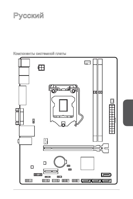
Благодарим вас за выбор системной платы серии H8M-P33/ H8M-E33/ H87M-
P33/ H87M-E33/ B85M-P33/ B85M-E33 (MS-787 v.X) Micro-ATX. Материнские
платы серии H8M-P33/ H8M-E33/ H87M-P33/ H87M-E33/ B85M-P33/
B85M-E33 на базе чипсета Intel H8/ H87/ B85 и обеспечивают оптимальную
производительность системы. Серия H8M-P33/ H8M-E33/ H87M-P33/
H87M-E33/ B85M-P33/ B85M-E33 обеспечивает высокую производительность
и является профессиональной платформой для настольных ПК, благодаря
совместимости с усовершенствованным процессором Intel LGA50.
Компоненты системной платы
Русский
00
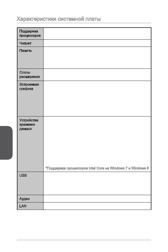
Характеристики системной платы
Поддержка
процессоров
Поддержка процессоров Intel
®
Core™ i7 / Core™ i5 / Core™
i3 / Pentium
®
/ Celeron
®
4-го поколения для сокета LGA 50
■
Чипсет Intel
®
H8/ H87/ B85 Express■
Память 2x DDR3 слота памяти с поддержкой до 6ГБ
Поддержка DDR3 600/ 333/ 066 МГц
Двухканальная архитектура памяти
Поддержка non-ECC, небуферизованной памяти
■
■
■
■
Слоты
расширения
x слот PCIe x6 (дополнительлно)
x слот PCIe 2.0 x
■
■
Встроенная
графика
x порт HDMI (дополнительлно), с поддержкой
x порт DVI-D (дополнительлно), с поддержкой
максимального разрешения 920x200 @ 60Гц, 24bpp
x порт VGA, с поддержкой максимального разрешения
920x200 @ 60Гц, 24bpp
■
■
■
Устройства
хранения
данных
Чипсет Intel H8/ H87/ B85 Express
4x портов SATA (дополнительно)
Поддержка RAID 0, RAID, RAID 5 и RAID 0
(дополнительно)
Поддержка Технологии Intel Smart Response
(дополнительно)*
Поддержка Технологии Intel Rapid Start
(дополнительно)*
Поддержка Технологии Intel Smart Connect
(дополнительно)*
*Поддержка процессоров Intel Core на Windows 7 и Windows 8
■
—
—
—
—
—
USB Чипсет Intel H8/ H87/ B85 Express
2x портов USB 3.0 на задней панели
8x портов USB 2.0 (4 порта на задней панели, 4 порта
доступны через внутренние USB разъемы*)
■
—
—
Аудио Realtek
®
ALC887 Codec■
LAN Realtek
®
RTL8G Гигабитный Сетевой контроллер■
Русский
0
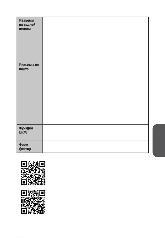
Разъемы
на задней
панели
x порт PS/2 клавиатуры
x порт PS/2 мыши
4x портов USB 2.0
2x порта USB 3.0
x порт HDMI (дополнительно)
x порт DVI-D (дополнительно)
x порт VGA
x порт LAN (RJ45)
3x аудиоразъемов
■
■
■
■
■
■
■
■
■
Разъемы на
плате
x 24-
контактный ATX основной разъем питания
x 4-
контактный ATX 2В разъем питания
4x разъемов SATA
2x разъемов USB 2.0 (Поддержка 4 дополнительных
портов USB 2.0)
x 4-
контактный разъем вентилятора ЦП
x 4-
контактный разъем вентилятора системы
x 3-
контактный разъем вентилятора системы
x аудиоразъем на передней панели
2x разъема панели системы
x разъем датчика открывания корпуса
x перемычка очистки CMOS
2x перемычки USB питания
■
■
■
■
■
■
■
■
■
■
■
■
Функции
BIOS
UEFI AMI BIOS
ACPI 5.0, PnP .0a, SM BIOS 2.7, DMI 2.0
Multi-язык
■
■
■
Форм-
фактор
Micro-ATX Форм-факторы
8.9 дюймов x 6.8 дюймов (22.6 см x 7.3 см)
■
■
Последние сведения о поддержке ЦП см. на веб-
странице http://www.msi.com/service/cpu-support/
Дополнительные сведения о совместимых компонентах
см. на веб-странице
http://www.msi.com/service/test-report/
Русский
02
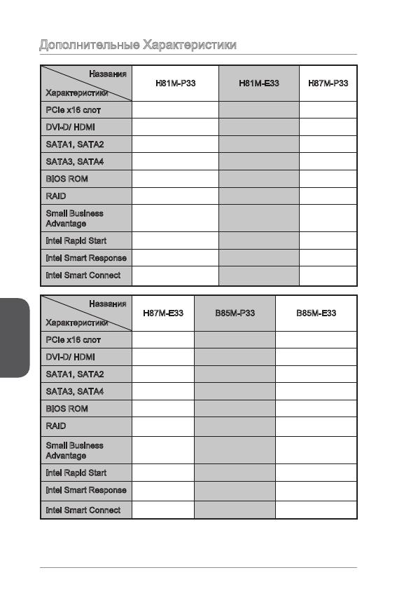
Дополнительные Характеристики
Названия
Характеристики
H8M-P33 H8M-E33 H87M-P33
PCIe x6 слот Gen2 Gen2 Gen3
DVI-D/ HDMI DVI-D HDMI DVI-D
SATA, SATA2 SATA 6Гб/с SATA 6Гб/с SATA 6Гб/с
SATA3, SATA4 SATA 3Гб/с SATA 3Гб/с SATA 6Гб/с
BIOS ROM 64Mб 64Mб 28Mб
RAID Не поддерживает Не поддерживает Поддержка
Small Business
Advantage
Не поддерживает Не поддерживает Поддержка
Intel Rapid Start Не поддерживает Не поддерживает Поддержка
Intel Smart Response Не поддерживает Не поддерживает Поддержка
Intel Smart Connect
Поддержка Поддержка Поддержка
Названия
Характеристики
H87M-E33 B85M-P33 B85M-E33
PCIe x6 слот Gen3 Gen3 Gen3
DVI-D/ HDMI HDMI DVI-D HDMI
SATA, SATA2 SATA 6Гб/с SATA 6Гб/с SATA 6Гб/с
SATA3, SATA4 SATA 6Гб/с SATA 3Гб/с SATA 3Гб/с
BIOS ROM 28Mб 28Mб 28Mб
RAID
Поддержка Не поддерживает Не поддерживает
Small Business
Advantage
Поддержка Поддержка Поддержка
Intel Rapid Start Поддержка Поддержка Поддержка
Intel Smart Response
Поддержка Не поддерживает Не поддерживает
Intel Smart Connect
Поддержка Поддержка Поддержка
Русский
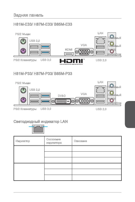
03
Задняя панель
Светодиодный индикатор LAN
LINK/ACT
LED
SPEED
LED
Индикатор
Состояние
индикатора
Описание
Link/ Activity LED
(Подключение/
Работа индикатора)
Выкл. Не подключен
Желтый Подключен
Мигает Передача данных
Speed LED
(Скорость
передачи данных)
Выкл. 0 Мбит/с подключение
Зеленый 00 Мбит/с подключение
Оранжевый Гбит/с подключение
H8M-E33/ H87M-E33/ B85M-E33
H8M-P33/ H87M-P33/ B85M-P33
PS/2 Мыши
PS/2 Клавиатуры
USB 2.0
USB 3.0
HDMI
VGA
Линейный
вход
Линейный
выход
Микрофон
USB 2.0
LAN
PS/2 Мыши
PS/2 Клавиатуры
USB 2.0
USB 3.0
DVI-D
VGA
Линейный
вход
Линейный
выход
Микрофон
USB 2.0
LAN
Русский
04
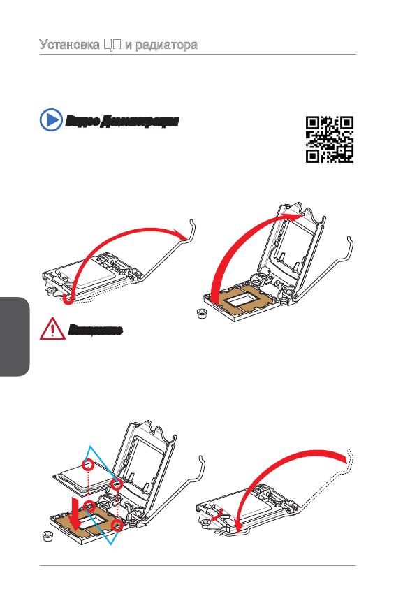
Установка ЦП и радиатора
При установке процессоора обязательно установите радиатор ЦП.Радиатор ЦП
предупреждает перегревание и обеспечивает стабильность работы системы.
Ниже представлены инструкции по правильной установке процессора и
радиатора ЦП.Неправильная установка приводит к выходу из строя процессора
и материнской платы.
. Отцепите и полностью поднимите рычаг фиксации.
2. При подъеме рычага фиксации автоматически поднимается прижимная
пластина.
Внимание
Не трогайте контакты разъема или нижней части процессора.
Видео Демонстрация
Смотрите видео,чтобы узнать как установить процессор и кулер:
http://youtu.be/bf5La099urI
Ключи совмещения
Выемки процессора
3. Выравняйте выемки на процессоре к ключами совмещения на сокете.
Опустите процессор вниз, без наклона или движения процессора в сокете.
Проверьте надежность установки процессора в сокете.
4. Закройте и сдвиньте прижимную пластину под ручку ужержания. Закройте и
зацепите рычаг фиксации.
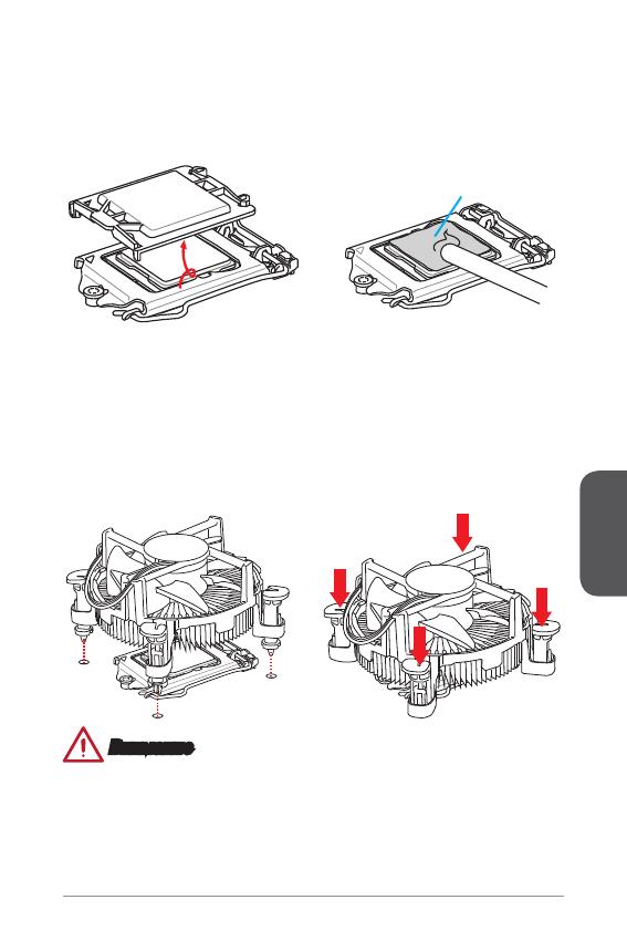
Русский
05
Термопаста
Внимание
Перед включением системы проверьте герметичность соединения между
процессором и радиатором.
Если процессор не установлен, всегда защищайте контакты процессорного
сокета пластиковой крышкой.
Если вы приобрели отдельно процессор и процессорный кулер, подробное
описание установки см. в документации в данному кулеру.
•
•
•
5. При нажатии на рычаг фиксации защитная крышка автоматически выскочит
из гнезда процессора. Не выбрасывайте защитную крышку. Всегда
устанавливайте защитную крышку, если процессор вынимается из сокета.
6. Равномерно нанесите тонкий слой термопасты (или термоленту) на
верхнюю крышку процессора. Это позволит увеличить теплопередачу и
предотвратит перегрев процессора.
7.
Найдите разъем для подключения вентилятора ЦП на материнской плате.
8. Установите кулер на материнскую плату, направив его кабель в сторону
разъема для подключения вентилятора.
9. Нажмите на радиатор сверху так, чтобы закрепить четыре защелки в
отверстиях на материнской плате. Нажмите на защелки для закрепления
вентилятора. Каждый из защелок фиксируется с характерным щелчком.
0. Осмотрите материнскую плату и определите правильность закрепления
зажимов.
. И, наконец, подключите кабель вентилятора процессора к разъему
вентилятора на системной плате.
Русский
06
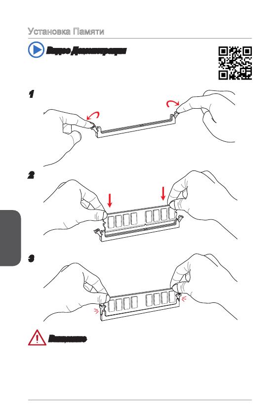
Установка Памяти
Видео Демонстрация
Смотрите видео,чтобы узнать как установить память по
указанному адресу.
2
3
Внимание
Модули DDR3 не взаимозаменяемы с модулями DDR2, стандарт DDR3 не
поддерживает обратную совместимость. Модули памяти DDR3 следует
устанавливать в разъемы DDR3 DIMM.
Для обеспечения стабильной работы системы в двухканальном режиме
устанавливаются модули памяти одинакового типа и емкости.
•
•
Русский
07
Внутренние разъемы
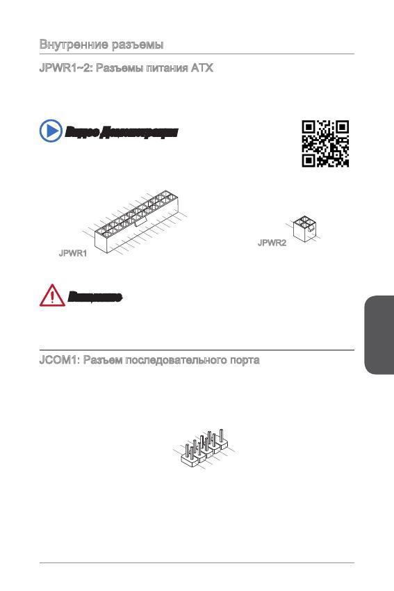
JPWR~2: Разъемы питания ATX
Эти разъемы предназначены для подключения разъема питания ATX. Для
подключения ATX разъема питания совместите кабель питания с разъемом и
прочно закрепите его. При правильном выполнении подключения защелка на
кабеле питания закрепляется в силовом разъеме материнской платы.
Видео Демонстрация
Смотрите видео,чтобы узнать как установить разъем питания.
13.+3.3
V
1.+3.3
V
14.—12V
2.+3.3
V
15.Ground
3
.Ground
16.PS—ON
#
4.+5
V
17.Ground
5
.Ground
18.Ground
6.+5
V
19.Ground
7
.Ground
22.+5
V
10.+12V
20.Res
8.PW
R O
K
23.+5
V
11
.+12V
21.+5
V
9.5VSB
24.Ground
12.+3.3
V
JPWR
4.+12V
2
.Ground
3.+12V
1
.Ground
JPWR2
Внимание
Для обеспечения стабильной работы системной платы проверьте надежность
подключения всех кабелей питания к соответствующему блоку питания АТХ.
JCOM: Разъем последовательного порта
Данный разъем является высокоскоростным последовательным портом
передачи данных 6550А с 6-разрядной передачей FIFO. К этому разъему
можно подключить устройство c последовательным интерфейсом.
1
.
D
C
D
3
.
S
O
U
T
1
0
.
N
o
P
i
n
5
.
G
r
o
u
n
d
7
.
R
T
S
9
.
R
I
8
.
C
T
S
6
.
D
S
R
4
.
D
T
R
2
.
S
I
N
Русский
08
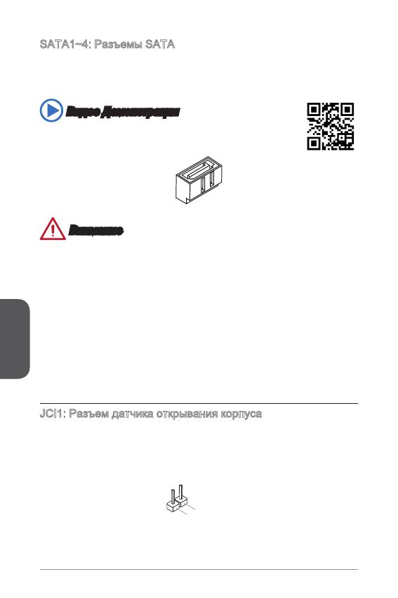
SATA~4: Разъемы SATA
Данный разъем является высокоскоростным интерфейсом SATA. К любому
разъему SATA можно подключить одно устройство SATA. К устройствам
SATA относятся жесткие диски, твердотельные накопители и накопители на
оптических дисках (компакт-диски/ DVD-диски/ Blu-Ray-диски).
Видео Демонстрация
Смотрите видео,чтобы узнать как установить SATA жесткие
диски.
Внимание
Многие устройства SATA требуют подключения к источнику питания с
помощью кабеля питания. К таким устройствам относятся жесткие диски,
твердотельные накопители и накопители на оптических дисках (компакт-
диски/ DVD-диски/ Blu-Ray-диски). Дополнительную информацию можно
получить в руководствах к соответствующим устройствам.
Во многих системных блоках устройства SATA большого размера (в том
числе, жесткие диски, твердотельные накопители и накопители на оптических
дисках) прикрепляются с помощью винтов. Дополнительные инструкции по
установке см. в руководствах к системному блоку или устройству SATA.
Избегайте перегибов кабеля SATA под прямым углом. В противном случае,
возможна потеря данных при передаче.
Кабели SATA оснащены одинаковыми вилками с обеих сторон. Однако для
экономии занимаемого пространства рекомендуется к материнской плате
подключать плоский разъем.
JCI: Разъем датчика открывания корпуса
К этому разъему подключается кабель датчика, установленного в корпусе. Этот
датчик срабатывает при вскрытии системного блока. Система запоминает это
событие и выдает предупреждение на экран. Для отключения предупреждения
необходимо удалить записанное событие в настройках BIOS.
•
•
•
•
Русский
09
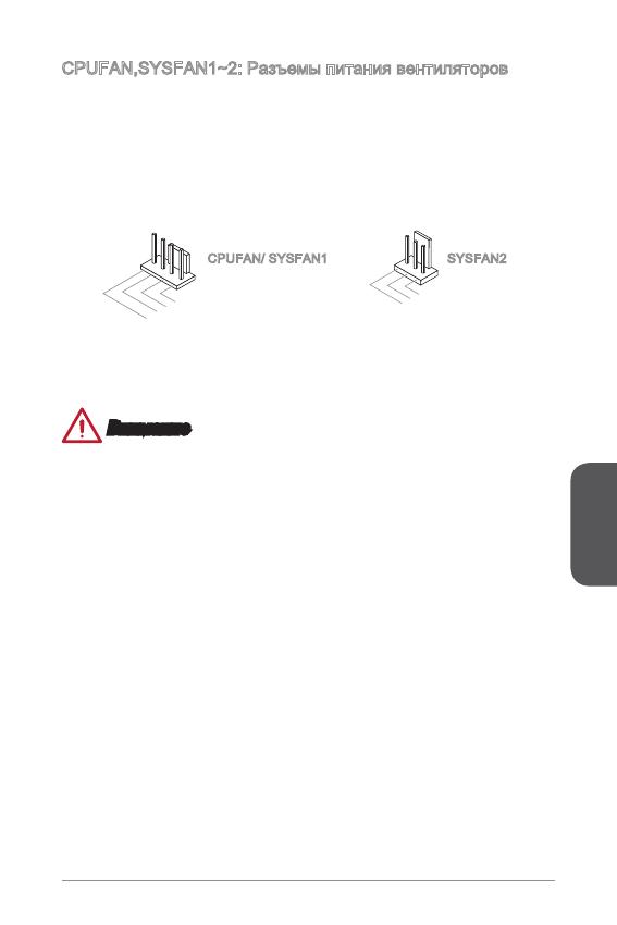
CPUFAN,SYSFAN~2: Разъемы питания вентиляторов
Разъемы питания вентиляторов поддерживают вентиляторы с питанием +2 В.
Если на системной плате установлена микросхема аппаратного мониторинга,
необходимо использовать специальные вентиляторы с датчиками скорости для
использования функции управления вентиляторами. Обязательно подключите
все системные вентиляторы. Некоторые системные вентиляторы невозможно
подключить к материнской плате.Вместо этого они подключаются к источнику
питания напрямую. Системные вентиляторы подключаются к свободным
разъемам для вентиляторов.
1
.Ground
2.+12V
3.Sens
e
4.Speed
C
ontro
l
CPUFAN/ SYSFAN SYSFAN2
Внимание
Для получения кулеров, рекомендованных для охлаждения процессора,
обратитесь на официальный веб-сайт производителя процессора или к
местному поставщику.
Эти разъемы поддерживают функцию управления скоростью вращения
вентиляторов в линейном режиме. Установите утилиту Command Center
для автоматического управления скоростью вращения вентиляторов в
зависимости от температуры процессора и системы.
В том случае, если на материнской плате не достаточно разъемов для
подключения всех системных вентиляторов, вентиляторы подключают
напрямую к источнику питания с помощью переходника.
Перед первой загрузкой проверьте, чтобы кабели не мешали вращению
вентиляторов.
•
•
•
•
Русский
0
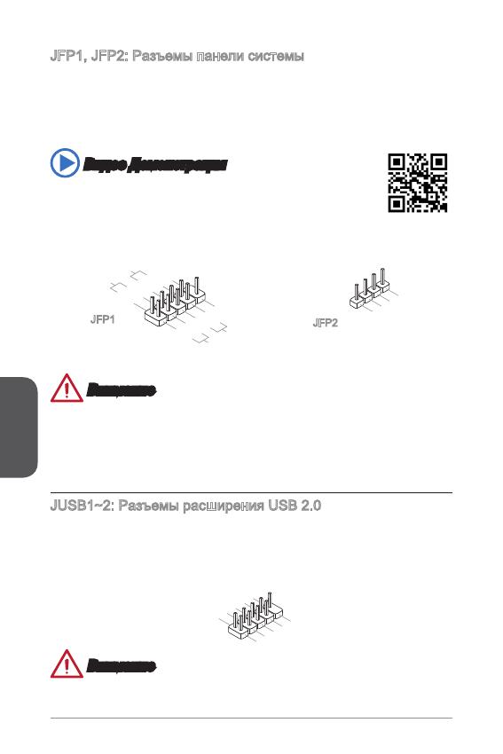
JFP, JFP2: Разъемы панели системы
Эти разъемы служат для подключения кнопок и светодиодных индикаторов,
расположенных на передней панели. Разъем JFP соответствует стандартам
Intel
®
Front Panel I/O Connectivity Design. При установке разъемов передней
панели для удобства используются переходники и кабели, входящие в комплект
поставки. Подключите все провода системного блока к разъемам, а затем
подключите разъемы к материнской плате.
Видео Демонстрация
Смотрите видео,чтобы узнать как подключить разъемы
передней панели.
3.Speaker
4.VCC5
1.Speaker
2.VCC5
1.
+
3.
—
10.No
Pi
n
5.
—
Reset
S
witch
HDD
LE
D
P
ower
S
witch
P
ower
LE
D
7.
+
9.Res erve
d
8.
—
6.
+
4.
—
2.
+
JFP
JFP2
Внимание
На разъемах, выходящих из системного блока, плюсовым проводам
соответствуют контакты, обозначенные небольшими треугольниками.
Для определения правильности направления и расположения служат
вышеуказанные схемы и надписи на дополнительных разъемах.
Большинство кнопок, расположенных на передней панели системного блока,
подключены к разъему JFP.
JUSB~2: Разъемы расширения USB 2.0
Этот разъем служит для подключения таких высокоскоростных периферийных
устройств, как жесткие диски с интерфейсом USB, цифровые камеры, МРЗ
плееры, принтеры, модемы и т. д.
1
.
V
C
C
3
.
U
S
B
0
—
1
0
.
NC
5
.
U
S
B
0
+
7
.
G
r
o
u
n
d
9
.
N
o
P
i
n
8
.
G
r
o
u
n
d
6
.
U
S
B
1
+
4
.
U
S
B
1
—
2
.
V
C
C
Внимание
Помните, что во избежание повреждений необходимо правильно подключать
контакты VCC и GND.
•
•
Русский
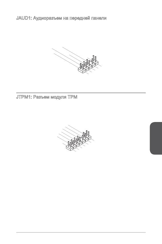
JAUD: Аудиоразъем на передней панели
Этот разъем служит для подключения аудиоразъема на передней панели
системного блока. Этот разъем соответствует стандарту Intel
®
Front Panel I/O
Connectivity Design.
1.MI
C L
3.MI
C R
10.Head
P
hone
Detection
5.Head
P
hone
R
7.SENSE_SEN
D
9.Head
P
hone
L
8.No
Pi
n
6.MI
C D
etection
4.NC
2
.Ground
JTPM: Разъем модуля ТРМ
Данный разъем подключается к модулю ТРМ (Trusted Platform Module).
Дополнительные сведения см. в описании модуля безопасности ТРМ.
10.No
Pi
n
14.Ground
8.5V
P
ower
12.Ground
6.Serial
IR
Q
4.3.3V
P
ower
2.3V
Standby
p
ower
1.LP
C C
loc
k
3.LP
C
Rese
t
5.LP
C a
ddres
s &
data
pin0
7.LP
C a
ddres
s &
data
p
in1
9.LP
C a
ddres
s &
data
pin2
11
.LPC
a
ddres
s &
data
pin3
13.LP
C
Fram
e
Русский
2
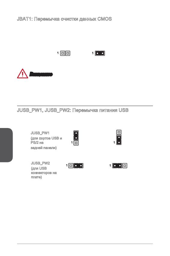
JBAT: Перемычка очистки данных CMOS
На плате установлена CMOS память с питанием от батарейки для хранения
данных о конфигурации системы. С помощью памяти CMOS операционная
система (ОС) автоматически загружается каждый раз при включении. Для
сброса конфигурации системы (очистки данных CMOS памяти), воспользуйтесь
этой перемычкой.
Сохранение
данных
Очистка
данных
Внимание
Очистка CMOS памяти производится замыканием указанных контактов
перемычкой при выключенной режиме. После выполнения очистки разомкните
перемычку. Очистка CMOS памяти во время работы системы не допустима, т.к.
это приведет к выходу материнской платы из строя.
JUSB_PW, JUSB_PW2: Перемычка питания USB
Данные джамперы используются для включения функции “Wake Up Event Setup”
посредством БИОС для USB или PS/2 устройства.
Поддержка
Не поддерживает (По
умолчанию)
JUSB_PW
(для портов USB и
PS/2 на
задней панели)
JUSB_PW2
(для USB
коннекторов на
плате)
Поддержка
Не поддерживает (По
умолчанию)
Русский
3
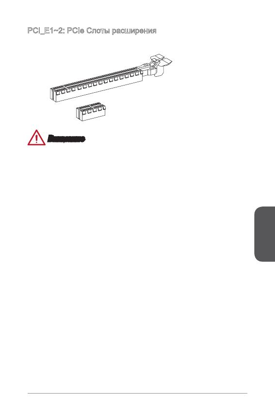
PCI_E~2: PCIe Слоты расширения
Слот PCIe поддерживает платы расширения с интерфейсом PCIe.
PCIe 2.0 x Слот
PCIe 3.0 x6 Слот
Внимание
Перед установкой или извлечением плат расширения убедитесь, что шнур
питания отключен от электрической сети. Прочтите документацию на карту
расширения и выполните необходимые дополнительные аппаратные или
программные изменения для данной карты.
Русский
4
Настройка BIOS
Параметры по умолчанию предлагают оптимальную производительность
для стабильности системы в нормальных условиях. Этот режим может
потребоватья в следующих условиях:
Во время загрузки системы появляется сообщение об ошибке с требованием
запустить SETUP.
В случае необходимости заменить заводские настройки на собственные.
Внимание
Пожалуйста, загрузите заводские настройки для восстановления
оптимальной производительности и стабильности системы, ести система
становится неустойчивой после изменения настроек BIOS. Выберите
«Восстановить настройки по умолчанию» и нажмите <Enter> в BIOS для
загрузки настройки по умолчанию.
Если вы не знакомы с настройками BIOS, мы рекомендуем сохранить
настройки по умолчанию для избежания возможности повреждения системы
или неудачи загрузки из-за неуместного конфигурирования BIOS.
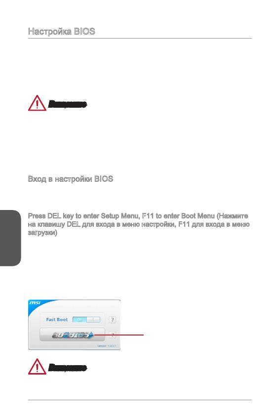
Вход в настройки BIOS
Включите компьютер и дождитесь начала процедуры самотестирования POST
(Power On Self Test). При появлении на экране сообщения, приведенного ниже,
нажмите клавишу <DEL> для запуска программы настройки:
Press DEL key to enter Setup Menu, F to enter Boot Menu (Нажмите
на клавишу DEL для входа в меню настройки, F для входа в меню
загрузки)
Если вы не успели нажать клавишу до отображения сообщения и по-прежнему
требуется войти в программу настройки, перезапустите систему, либо
включив и выключив ее, либо нажав кнопку RESET. Можно также выполнить
перезагрузку, одновременно нажав клавиши <Ctrl>+<Alt>+<Delete>.
MSI также дополнительно предоставляет два метода для входа в настройки
BIOS. Вы можете нажать “GO2BIOS” на экране в утилите “MSI Fast Boot” или
нажать физическую кнопку “GO2BIOS» (опционально) на материнской плате для
непосредственно входа в настройки BIOS при следующей загрузке.
Нажмите «GO2BIOS» на экране
утилиты «MSI Fast Boot».
Внимание
Не забудьте установить “MSI Fast Boot” до того как войти в настройки BIOS.
■
■
•
•
Русский
5
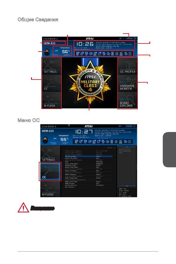
Общие Сведения
После входа в BIOS отображается следующий экран.
Выбор
меню BIOS
Мониторинг температур
Системная
Информация
Приоритет
загрузочных
устройств
Экран просмотра раздела
Выбор
меню BIOS
Язык
Кнопка Virtual
OC Genie
Название
модели
Меню OC
Внимание
Разгонять ПК вручную рекомендуется только опытным пользователям.
Производитель не гарантирует успешность разгона. Неправильное
выполнение разгона может привести к аннулированию гарантии и серьезному
повреждению оборудования.
Неопытным пользователям, рекомендуется использовать OC Genie.
•
•
•
Русский
6
Current CPU/ DRAM/ Ring Frequency
Эти элементы показывают текущие частоты установленного процессора,
памяти и шины Ring. Эти значения нельзя изменять.
CPU Ratio Mode [Auto]
Выбор множителя процессора.
[Auto] Этот параметр будет настроен автоматически с помощью
BIOS.
[Fixed Mode] Фиксирует множитель процессора.
[Dynamic Mode] Множитель процессора будет меняться в зависимости от
загрузки процессора.
Adjust CPU Ratio [Auto]
Задание множителя процессора для установки его тактовой частоты
процессора. Изменение данного параметра возможно только в том случае, если
процессор поддерживает данную функцию.
Adjusted CPU Frequency
Показывает текущую частоту ЦП. Это значение нельзя изменять.
EIST [Enabled]
Включение или выключение технологии Enhanced Intel
®
SpeedStep.
Intel Turbo Boost [Enabled]
Включение или выключение Intel
®
Turbo Boost. Этот пункт появляется, когда
установленный процессор поддерживает данную функцию.
[Enabled] Включение этой функции приводит к автоматическому
увеличению производительности процессора.
[Disabled] Функция выключена.
Enhanced Turbo [Auto]
Функция Enhanced Turbo позволяет увеличивать частоту на всех ядрах
процессора.
[Auto] Этот параметр будет настроен автоматически с помощью
BIOS.
[Enabled] Увеличение частоты всех процессорных ядер до
максимального значения.
[Disabled] Функция выключена.
Adjust Ring Ratio [Auto]
Установка множителя шины Ring. Диапазон допустимых значений зависит от
установленного процессора.
Adjusted Ring Frequency
Показывает скорректированную частоту шины Ring. Это значение нельзя
изменять.
Adjust GT Ratio [Auto]
Установка множителя для интегрированной графики. Диапазон допустимых
значений зависит от установленного процессора.
▶
▶
▶
▶
▶
▶
▶
▶
▶
▶
Русский
7
Adjusted GT Frequency
Показывает настроенную частоту интегрированной графики. Это значение
нельзя изменять.
DRAM Frequency [Auto]
Установка частоты памяти (DRAM). Обратите внимание, что возможность
успешного разгона не гарантируется.
Adjusted DRAM Frequency
Показывает текущую частоту DRAM. Это значение нельзя изменять.
DRAM Timing Mode [Auto]
Режимы таймингов памяти.
[Auto] Временные параметры DRAM устанавливаются на основе
SPD (Serial Presence Detect) модуля памяти.
[Link] Позволяет пользователю настроить тайминги DRAM вручную
для всех каналов памяти.
[UnLink] Позволяет пользователю настроить тайминги DRAM вручную
для соответствующего канала памяти.
Advanced DRAM Conguration
Нажмите <Enter> для входа в подменю. Данное подменю будет доступно после
установки [Link] или [Unlink] в режиме “DRAM Timing Mode”. Пользователь
может настроить тайминги для каждого канала памяти. Система может
работать нестабильно или не загружается после изменения тамингов памяти.
Если система работает нестабильно, пожалуйста, очистите данные CMOS
и восстановите настройки по умолчанию. (см. перемычка очистки данных
CMOS/раздел кнопки для очистки данных CMOS и вход в BIOS, чтобы загрузить
настройки по умолчанию.)
Memory Fast Boot [Auto]
Включает или выключает инициализацию тренировки памяти при каждой
загрузке.
[Auto] Этот параметр будет настроен автоматически с помощью
BIOS.
[Enabled] Память будет полностью имитирует настройки при первой
инициализации и тренировке. После этого память не будет
инициализированна с измененными настройками для
ускорения загрузки.
[Disabled] Память будет инициализирована и тренирована при каждой
загрузке.
DRAM Voltage [Auto]
Установка напряжения памяти. Если значение установлено в “Auto”, BIOS
устанавливает напряжения на памяти автоматически. Вы также можете
настроить его вручную.
Spread Spectrum
Данная функция уменьшает EMI (электромагнитные помехи), вызванные
колебаниями импульсного генератора тактовых сигналов.
▶
▶
▶
▶
▶
▶
▶
▶