- Manuals
- Brands
- GW Instek Manuals
- Measuring Instruments
- LCR Series
- User manual
-
Contents
-
Table of Contents
-
Bookmarks
Quick Links
All manuals and user guides at all-guides.com
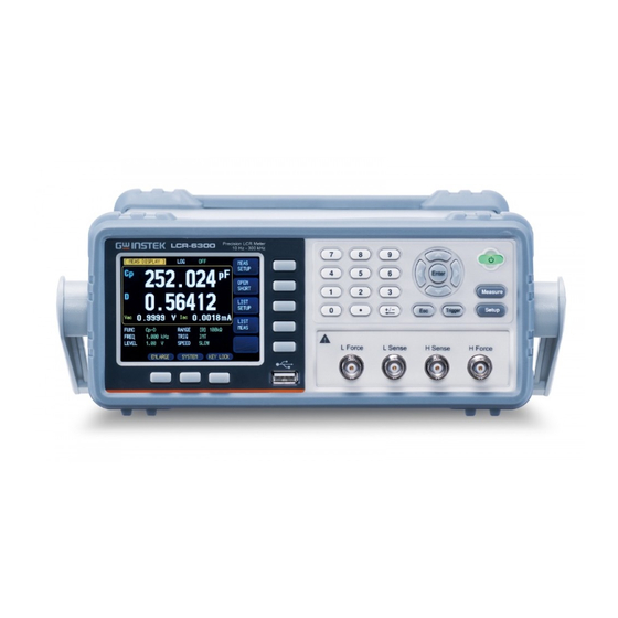
LCR Meter
LCR-6300/6200/6100/6020/6002
User’s Guide
VERSION: 1.04
ISO-9001 CERTIFIED MANUFACTURER
Related Manuals for GW Instek LCR Series
Summary of Contents for GW Instek LCR Series
-
Page 1
All manuals and user guides at all-guides.com LCR Meter LCR-6300/6200/6100/6020/6002 User’s Guide VERSION: 1.04 ISO-9001 CERTIFIED MANUFACTURER… -
Page 2
All manuals and user guides at all-guides.com This manual contains proprietary information, which is protected by copyright. All rights are reserved. No part of this manual may be photocopied, reproduced or translated to another language without prior written consent of the Good Will company. -
Page 3
All manuals and user guides at all-guides.com LCR-6000 Series User Manual Safety Summary Warning Dangerous When you notice any of the unusual conditions listed below, immediately terminate operation and disconnect the power cable. Please contact the GWINSTEK service center representative for repair of the instrument. -
Page 4
All manuals and user guides at all-guides.com Safety Summary Operating personnel must not remove instrument Keep Away From Live covers. Component replacement and internal Circuits adjustments must be made by qualified maintenance personnel. Do not replace components with the power cable connected. Under certain conditions, dangerous voltages may exist even with the power cable is removed. -
Page 5: Table Of Contents
All manuals and user guides at all-guides.com LCR-6000 Series User Manual Table of Contents 1. UNPACKING AND PREPERATION ………..11 Incoming Inspection ……………. 11 Environmental Requirements …………12 Cleaning ……………….. 12 How to Remove the Handle …………13 2. OVERVIEW ………………14 Introduction ………………
-
Page 6
All manuals and user guides at all-guides.com Table of Contents 3. STARTUP………………..21 Front panel ………………21 Rear Panel ………………22 Power On/Off …………….. 22 3.3.1 Power On ……………… 22 3.3.2 Power Off …………….. 22 Warm‐up Time …………….. 23 Connect to the Device Under Test (DUT) ……..23 4. -
Page 7
All manuals and user guides at all-guides.com LCR-6000 Series User Manual 4.5.1 Enlarge Display ……………. 49 4.5.2 Direct Comparison Function ……….50 5. SETUP KEY ………………51 [MEAS SETUP] Page …………..51 5.1.1 Source Output Impedance [SRC RES] ……… 52 5.1.2 Averaging Factor [AVG] ………… -
Page 8
All manuals and user guides at all-guides.com Table of Contents 6.1.5 TERMINATOR…………… 72 6.1.6 Hand Shake …………….72 6.1.7 Error Code …………….73 6.1.8 Result ………………74 6.1.9 DATA BUFFER …………..74 6.1.10 DEFAULT SET …………..75 [SYSTEM INFO] Page …………..76 7. -
Page 9
All manuals and user guides at all-guides.com LCR-6000 Series User Manual 11.6.2 DISP:PAGE …………….98 11.7 FUNCtion Subsystem …………..100 11.7.1 FUNCtion …………….100 11.7.2 FUNCtion:IMPedance:AUTO ……….101 11.7.3 FUNCtion:IMPedance:RANGe ……….. 101 11.7.4 FUNCtion:DCR:RANGe …………. 101 11.7.5 FUNCtion:RANGe:AUTO ……….102 11.7.6 FUNCtion:MONitor 1 /2…………. -
Page 10
All manuals and user guides at all-guides.com Table of Contents 11.11.8 COMParator:BEEP …………114 11.11.9 COMParator:OPEN …………114 11.12 LIST Subsystem …………….115 11.12.1 LIST:PARAmeter …………115 11.12.2 LIST:STAT …………..115 11.12.3 LIST:BAND …………..116 11.13 CORRection Subsystem …………… 117 11.13.1 CORRection:OPEN ………… -
Page 11
All manuals and user guides at all-guides.com LCR-6000 Series User Manual 11.18.1 SYSTem:SHAKehand………… 124 11.18.2 SYSTem:CODE …………. 124 11.18.3 SYSTem:KEYLock …………125 11.18.4 SYSTem:RESult………….. 125 11.19 Common Commands …………..125 11.19.1 *IDN? …………….125 11.19.2 *TRG …………….125 11.19.3 *SAV …………….126 11.19.4 *RCL ……………. -
Page 12
All manuals and user guides at all-guides.com Table of Contents Table of Figures Figure 1 -1 How to remove the handle …………. 13 Figure 2 -1 Disk Ready ………………19 Figure 2 -2 Screen Saved ………………19 Figure … -
Page 13
All manuals and user guides at all-guides.com LCR-6000 Series User Manual Figure 1 1-6 APERture Subsystem Command Tree ……..107 Figure 1 1-7 FETCh Subsystem Command Tree ……….108 Figure 1 1-8 COMParator Subsystem Command Tree ……..111 Figure … -
Page 14
All manuals and user guides at all-guides.com Table of Contents List of Tables Table 2-1 Equivalent Circuit …………….15 Table 2-2 Display Range ………………. 16 Table 3-1 Front panel description …………..21 Table 3-2 Rear panel description …………..22 Table 4-1 Measurement parameter combinations ……… -
Page 15: Unpacking And Preperation
All manuals and user guides at all-guides.com LCR-6000 Series User Manual NPACKING AND PREPERATION This chapter describes how to set up and start the LCR-6000 Series LCR Meter. Incoming Inspection Environmental Requirements Cleaning How to Remove the Handle …
-
Page 16: Environmental Requirements
UNPACKING AND PREPERATION If an abnormality is detected, contact the company and Note transport the meter to your nearest GW INSTEK Instruments sales or service office. Save the packing box, shock-absorbing material, and packaged items as you received them in case you need to mail the instrument to an authorized GW Instek distributor or service center.
-
Page 17: How To Remove The Handle
All manuals and user guides at all-guides.com LCR-6000 Series User Manual 1.4 How to Remove the Handle A handle kit is attached to the LCR-6000 Series: Figure 1 -1 How to remove the handle Retracted Carrying Position Extended Remove Handle (Lift the handle perpendicular to the unit while pulling it in the direction of 1.)
-
Page 18: Overview
2.1 Introduction Thank you for purchasing an LCR-6000 Series LCR meter. The GW INSTEK LCR-6000 Series is a general-purpose LCR meter for incoming inspection of components, quality control, and laboratory use. The LCR-6000 Series is used for evaluating LCR…
-
Page 19: Main Specifications And Features
All manuals and user guides at all-guides.com LCR-6000 Series User Manual 2.2 Main Specifications and Features 2.2.1 Test Function Cs-Rs, Cs-D, Cp-Rp, Cp-D, Lp-Rp, Lp-Q, Ls-Rs, Ls-Q, Rs-Q, Rp-Q, R-X, DCR, Z-θr, Z-θd, Z-D, Z-Q 2.2.2 Equivalent Circuit Serial and Parallel Table …
-
Page 20: Trigger Mode
All manuals and user guides at all-guides.com Overview NOTE *1. Measurement speed in 300kHz, typical. 2.2.5 Trigger Mode Includes Internal, Manual, External and Bus Trigger. 2.2.6 Basic Accuracy 0.05%@SLOW/MED 0.1%@FAST 2.2.7 Display Range Table 2 -2 Display Range Parameter Display Range 0.00001uH ~ 9999.99H 0.00001pF ~ 9999.99mF…
-
Page 21: Test Signal Level
All manuals and user guides at all-guides.com LCR-6000 Series User Manual 2.3.2 Test Signal Level 10.00mV- 2.00V (± 10%) CV mode:10.00mV- 2.00V(± 6%) 100.0uA- 20.00mA (± 10%) CC mode:100.0uA- 20.00mA(± 6%) @2VMax DCR: ± 1V(2Vpp), Square wave, 3Hz up 0.033A(Max), Output impedance fixed 30Ω 2.3.3 Output impedance 30Ω, 50Ωand 100Ω…
-
Page 22: List Sweep
All manuals and user guides at all-guides.com Overview 2.4.3 List Sweep Points There is a maximum of 10 points. Sweep parameters Test frequency, test voltage, test current. Comparator function of list sweep The comparator function enables you to set one pair of lower and upper limits for each measurement point.
-
Page 23: Figure 2 -1 Disk Ready
All manuals and user guides at all-guides.com LCR-6000 Series User Manual Save Screen After a USB disk has been inserted into the USB host port of the LCR meter and if the meter detects that the USB disk is usable, the meter will show “USB Disk Ready.
-
Page 24: Dc Bias Voltage
All manuals and user guides at all-guides.com Overview 2.6.2 DC Bias Voltage 0V ~ ± 2.5V Accuracy: ± 0.5%+0.005V…
-
Page 25: Startup
All manuals and user guides at all-guides.com LCR-6000 Series User Manual TARTUP This chapter describes names and functions of the front panel, rear panel, and screen display and provides the basic procedures for operating the LCR- 6000 Series. Front panel summary …
-
Page 26: Rear Panel
All manuals and user guides at all-guides.com Startup Trigger Key ESC Key USB Disk Port (USB-Host) System Soft-key 3.2 Rear Panel Figure 3 -2 Rear Panel Table 3 -2 Rear panel description Description Power Cable Receptacle(Outlet) (to LINE) Frame Terminal RS-232C Interface Handler Interface…
-
Page 27: Warm-Up Time
All manuals and user guides at all-guides.com LCR-6000 Series User Manual 3.4 Warm‐up Time LCR-6000 Series is ready to be used as soon as the power-up sequence has completed. However, to achieve the specification accuracy, first warm up the instrument for 30 minutes.
-
Page 28: Measure Key
All manuals and user guides at all-guides.com Measure Key EASURE KEY This section includes the following information: MEAS DISPLAY page OPEN/SHORT page LIST SETUP page LIST MEAS page 4.1 [MEAS DISPLAY] Page When the [Measure] key is pressed, the [MEAS DISPLAY] page appears.
-
Page 29: Measurement Function [Func]
All manuals and user guides at all-guides.com LCR-6000 Series User Manual Figure 4 -1 [MEAS DISPLAY] Page 4.1.1 Measurement Function [FUNC] The LCR-6000 Series simultaneously measures four components of complex impedance (parameters) in a measurement cycle. These include a primary parameter, a secondary parameter and two monitor parameters.
-
Page 30: Table 4-3 Measurement And Monitor Parameter Descriptions
All manuals and user guides at all-guides.com Measure Key Table 4 -3 Measurement and Monitor parameter descriptions Parameter Description Capacitance value measured using the series equivalent circuit model Capacitance value measured using the parallel equivalent circuit model Inductance value measured using the series equivalent circuit model Inductance value measured using the parallel equivalent circuit model…
-
Page 31: Impedance Range [Range]
All manuals and user guides at all-guides.com LCR-6000 Series User Manual 4.1.2 Impedance Range [RANGE] Impedance range mode To achieve the best measurement result, it is recommended to set the impedance range mode to “Auto range”. When using “Hold range”, errors in measurement results may occur if the measured value exceeds the full scale of the selected range.
-
Page 32: Table 4-5 Effective Measurement Range For The Impedance Range When In Hold State
All manuals and user guides at all-guides.com Measure Key Table 4 -5 Effective measurement range for the impedance range when in HOLD state. Range Impedance Effective measurement range range 10Ω 0 — 10Ω 30Ω 10Ω-100Ω 100Ω 100Ω-316Ω 300Ω 316Ω-1kΩ 1kΩ…
-
Page 33: Test Frequency [Freq]
All manuals and user guides at all-guides.com LCR-6000 Series User Manual Procedure for setting the impedance range [RANGE] Step 1. Press the [Measure] key. Step 2. Use the cursor key to select the [RANGE] field. Step 3. Use the soft-keys to select the impedance range mode or impedance range.
-
Page 34: Table 4-8 Lcr-6300’S Predefined Test Frequencies That Can Be Selected By Using Incr+/Decr
All manuals and user guides at all-guides.com Measure Key Procedure for setting test frequency [FREQ] Step 1. Press the [Measure] key. Step 2. Use the cursor key to select the [FREQ] field. Step 3. Use the soft-keys or numeric entry keys to enter the test frequency.
-
Page 35: Trigger Mode [Trig]
All manuals and user guides at all-guides.com LCR-6000 Series User Manual Table 4 -12 LCR-6002’s predefined test frequencies that can be selected by using INCR+/DECR‐ INCR+/DECR- 10Hz 50Hz 60Hz 100Hz 120Hz 1kHz 2kHz 4.1.4 Trigger Mode [TRIG] LCR-6000 Series supports four trigger modes: INT (internal), EXT (external), MAN (manual) and BUS (RS- 232).
-
Page 36: Test Signal Voltage/Current Level [Level]
All manuals and user guides at all-guides.com Measure Key 4.1.5 Test Signal Voltage/Current Level [LEVEL] The LCR-6000 Series’ test signal voltage/current level can be set as the effective value (RMS value) of a sine wave of the test frequency from the unit’s internal oscillator.
-
Page 37: Measurement Speed [Speed]
All manuals and user guides at all-guides.com LCR-6000 Series User Manual 4.1.6 Measurement Speed [SPEED] SLOW, MED and FAST can be selected for LCR-6000 Series. SLOW mode will result in more stable and accurate measurement results. Procedure for setting measurement speed mode Step 1.
-
Page 38: Measurement Log [Log]
All manuals and user guides at all-guides.com Measure Key 26.5 88.5 24.5 100k 88.5 24.5 300k 88.5 24.5 4.1.7 Measurement log [LOG] The LCR-6000 has an internal data buffer that record up to 10000 measurement readings. These readings can be saved to an external USB drive in a .csv file format.
-
Page 39
All manuals and user guides at all-guides.com LCR-6000 Series User Manual SAVE TO USB Saves the recorded readings in the buffer to an external USB flash drive. The internal buffer is cleared after this operation. CLEAR Clears the internal buffer. BUFFER SAVE &… -
Page 40: Open/Short] Page
All manuals and user guides at all-guides.com Measure Key Before saving the recorded readings in the internal buffer to the external USB flash drive, remember to plug the external USB drive into the USB port on the front panel. The recorded readings will be saved in a subdirectory named MEAS DATA, whose parent directory will have the same name as the LCR-6000 model being used.
-
Page 41: Open Correction [Open]
All manuals and user guides at all-guides.com LCR-6000 Series User Manual Figure 4 -2 [OPEN/SHORT] Page 4.2.1 Open Correction [OPEN] The LCR-6000 Series’ OPEN correction capability cancels errors due to the stray admittance (G, B) in parallel with the device under test (Refer to Figure 4 -3). Figure …
-
Page 42: Short Correction [Short]
All manuals and user guides at all-guides.com Measure Key Disables open correction. MEAS OPEN Starts open correction (AC). DCR OPEN Starts open correction (DC). Step 4. Press the [MEAS OPEN] or [DCR OPEN] soft-key. A dialog message, “Open-circuit the test terminals” will appear. Step 5.
-
Page 43: Spot Correction
All manuals and user guides at all-guides.com LCR-6000 Series User Manual Step 1. Press the [Measure] key. Step 2. Press the [OPEN SHORT] soft-key. Step 3. Use the cursor key to select the [SHORT] field. Soft-key Function Enables short correction. Disables short correction.
-
Page 44
All manuals and user guides at all-guides.com Measure Key To specify frequency points and perform open correction Step 1. Press the [Measure] key. Step 3. Press the [OPEN SHORT] soft-key. Step 3. Use the cursor key to select the [SPOT] field. Step 4. -
Page 45: List Setup] Page
All manuals and user guides at all-guides.com LCR-6000 Series User Manual To specify frequency points and perform short correction Step 1. Press the [MEAS SHORT] soft key, a dialog message, “Short-circuit the test terminals”, will be displayed. Step 2. Connect the test fixture to the BNC terminals and short-circuit the test terminals.
-
Page 46: Measurement Function [Func]
All manuals and user guides at all-guides.com Measure Key Figure 4 -5 [LIST SETUP] Page 4.3.1 Measurement Function [FUNC] Select the primary and the secondary measurement here. 4.3.2 Test Mode [MODE] The [LIST MEAS] page will execute a list of up to 10 swept frequency or amplitude tests.
-
Page 47: List Measurement Parameters
All manuals and user guides at all-guides.com LCR-6000 Series User Manual Trigger Mode Function Trigger by the meter’s internal trigger source. Trigger by pressing the trigger button. Trigger by sending a signal to the trigger pin on the handler interface. Trigger by the RS-232 port.
-
Page 48: List Point And Limit Modes
All manuals and user guides at all-guides.com Measure Key 4.3.4 List Point and Limit Modes The List measurement feature supports up to 10 list points as well as measurement limit values. Each list point can be turned on or off. To configure the list points: Step 1.
-
Page 49: List Meas] Page
All manuals and user guides at all-guides.com LCR-6000 Series User Manual 4.4 [LIST MEAS] Page The [LIST MEAS] page will appear when you press the [Measure] key and then the [LIST MEAS] soft-key. Figure 4 -6 [LIST MEAS] Page On the [LIST MEAS] page, the list points are swept and the measurement results are compared to the limits.
-
Page 50: Test Mode [Mode]
All manuals and user guides at all-guides.com Measure Key Trigger mode When entering LIST MEAS for the first time, the system will set Trig Mode to MAN and automatically performs a measurement. Trig Mode Function Internal Trigger. All ten list points are swept continuous.
-
Page 51: Range Mode [Range]
All manuals and user guides at all-guides.com LCR-6000 Series User Manual There are 4 available trigger modes in the [LIST MEAS] page. Trigger Modes Function Trigger by the meter’s internal trigger source. Trigger by pressing the trigger button. Trigger by sending a signal to the trigger pin on the handler interface.
-
Page 52
All manuals and user guides at all-guides.com Measure Key Soft-key Function SAVE & STOP Stops the recording and saves the recorded readings in the internal buffer to an external USB flash drive. The internal buffer will be cleared after the save operation. If an external USB flash drive is not plugged in, the meter will not stop the ongoing recording. -
Page 53: Enlarge Display] Page
All manuals and user guides at all-guides.com LCR-6000 Series User Manual 4.5 [ENLARGE DISPLAY] Page Only four measurement values will be shown in this simplified display mode: The primary measurement parameters, the secondary measurement parameters and two monitored parameters such as △, △%, Iac or Vac, etc.
-
Page 54: Direct Comparison Function
All manuals and user guides at all-guides.com Measure Key Figure 4 -7 [ENLARGE DISPLAY] Page 4.5.2 Direct Comparison Function The Direct Comparison function can be turned on in the [BIN SETUP] page. When the number of bins is set to 1 in the [BIN SETUP] page, the Direct Comparison function will be activated for the [ENLARGE DISPLAY] mode.
-
Page 55: Setup Key
All manuals and user guides at all-guides.com LCR-6000 Series User Manual ETUP KEY This section includes the following information: MEAS SETUP page BIN SETUP page BIN MEAS page BIN COUNT page Every time or everywhere you can press the [Setup] key to open the [MEAS SETUP] page.
-
Page 56: Source Output Impedance [Src Res]
All manuals and user guides at all-guides.com Setup Key In the [MEAS SETUP] Page, you can configure each of the following measurement controls with the cursor placed in the corresponding field. Measurement Function [FUNC] Impedance range [RANGE] Test Frequency [FREQ] …
-
Page 57: Averaging Factor [Avg]
All manuals and user guides at all-guides.com LCR-6000 Series User Manual Soft-key Function 30Ω 30Ω 50Ω 50Ω 100Ω 100Ω 5.1.2 Averaging Factor [AVG] The averaging feature allows you to obtain moving average values of successive measurement results. You can specify the averaging factor from integer 1 to integer 256.
-
Page 58: Auto Lcz Function [Auto Lcz]
All manuals and user guides at all-guides.com Setup Key test. -2V voltage is applied to the device under test. Bias Voltage range Resolution 0.01V ≦ DC BIAS ≦ 2.50V 0.01V -2.50V≦ DC BIAS ≦ -0.01V 0.01V 5.1.4 Auto LCZ Function [AUTO LCZ] Auto LCZ Function can help you to select a proper measurement parameter.
-
Page 59: Measurement Delay [Delay]
All manuals and user guides at all-guides.com LCR-6000 Series User Manual Procedure for setting monitor parameters (monitor 1 and monitor 2) Step 1. Press the [Setup] key. Step 2. Use the cursor key to select [MON 1] or [MON 2] field. Step 3.
-
Page 60: Nominal Value [Nominal]
All manuals and user guides at all-guides.com Setup Key NOTE In situations when the actual measuring Vac or Iac goes beyond the extent that the ALC can regulate, a warning message, “Failed! ALC can’t regulate!”, will be shown at the bottom of the screen to indicate to the operator that the ALC can no longer regulate Vac/Iac.
-
Page 61: Bin Setup] Page
All manuals and user guides at all-guides.com LCR-6000 Series User Manual 5.2 [BIN SETUP] Page Press [Setup] key and press the [BIN SETUP] soft-key to open [BIN SETUP] page. This page allows you to configure the LCR-6000 Series’ built-in comparator. The built-in comparator can sort DUTs into a maximum of 10 levels (BIN1 through BIN9 and OUT) using up to nine sets of primary parameter limits along with one set of secondary parameter limits.
-
Page 62: Measurement Function [Func]
All manuals and user guides at all-guides.com Setup Key Figure 5 -2 [BIN SETUP] Page 5.2.1 Measurement Function [FUNC] The LCR-6000 Series simultaneously measures four components of the complex impedance (parameters) in a measurement cycle. These include primary parameter, secondary parameter and two monitor parameters.
-
Page 63: Figure 5 -3 Page Comparator Workflow
All manuals and user guides at all-guides.com LCR-6000 Series User Manual Figure 5 -3 Page Comparator Workflow Sorting Start COMP=ON BIN1 <Primary<BIN1 …. BIN9 <Primary<BIN9 AUX=ON AUX=ON Lower<Secondary<Upper Lower<Secondary<Upper Display: OUT AUX NG Display: BIN1-9 AUX NG Display: BIN1-9 OK Display: OUT NG Output: NG Output: NG…
-
Page 64: Auxiliary Bin [Aux]
All manuals and user guides at all-guides.com Setup Key 5.2.3 Auxiliary Bin [AUX] After AUX is turned on, DUTs that do not fall within the primary parameter limit values are sorted as OUT. In addition, DUTs that fall within the primary parameter limits but are out of the secondary parameter limits are sorted into the auxiliary (AUX) bin.
-
Page 65: Figure 5 -4 Absolute Mode
All manuals and user guides at all-guides.com LCR-6000 Series User Manual Absolute mode[ABS] Absolute value (Δ) = UNKNOWN value – nominal value Figure 5 -4 Absolute mode Includes the point ● ○ Excludes the point Percentage mode [PER] Deviation percentages (%) = Absolute value (Δ)/nominal value ×…
-
Page 66: Figure 5 -6 Sequential Mode
All manuals and user guides at all-guides.com Setup Key Sequential mode[SEQ] Figure 5 -6 Sequential mode Includes the point ● ○ Excludes the point In Sequential mode, the comparison limit values are based on the absolute value of the measurement. The nominal value does not need to participate in operation.
-
Page 67: Nominal Value For Tolerance Mode
All manuals and user guides at all-guides.com LCR-6000 Series User Manual 5.2.5 Nominal value for tolerance mode You must configure the nominal value when you use tolerance mode as the limit mode for the primary parameter. In sequential mode the nominal value does not affect sorting.
-
Page 68: Lower And Upper Limits
All manuals and user guides at all-guides.com Setup Key Soft-key Function 1-BINS Set to 1 bin 2-BINS Set to 2 bins 3-BINS Set to 3 bins 4-BINS Set to 4 bins 5-BINS Set to 5 bins 6-BINS Set to 6 bins 7-BINS Set to 7 bins 8-BINS…
-
Page 69: Comparator Function On/Off
All manuals and user guides at all-guides.com LCR-6000 Series User Manual Figure 5 -7 [BIN MEAS] Page This page provides the following information: FUNC, RANGE, FREQ, LEVEL, TRIG, LEVEL, SPEED: These conditions can be set from [MEAS DISPLAY] page. Comparator function ON/OFF [COMP].
-
Page 70: Auxiliary Bin [Aux]
All manuals and user guides at all-guides.com Setup Key Soft-key Function Turns OFF the COMP function Turns ON the COMP function 5.3.2 Auxiliary Bin [AUX] After AUX is turned on, DUTs that do not fall within the primary parameter limit values are sorted as OUT. In addition, DUTs that fall within the primary parameter limits but out of the secondary parameter limits are sorted into the auxiliary (AUX) bin.
-
Page 71: Counter Function [Count]
All manuals and user guides at all-guides.com LCR-6000 Series User Manual 5.4.1 Counter Function [COUNT] The number of DUTs sorted into each bin is counted while the unit sorts the DUTs into the appropriate bins using the comparator function. When the maximum count of 99999999 is reached, the counting operation stops and the overflow message “———”…
-
Page 72: System Configurations
All manuals and user guides at all-guides.com System Configurations YSTEM CONFIGURATIONS This section includes the following information: SYSTEM CONFIG page SYSTEM INFO page SYSTEM SERVICE page 6.1 [SYSTEM CONFIG] Page When the [Measure] or [Setup] key is pressed, followed by the [SYSTEM] bottom soft-key, the [SYSTEM CONFIG] page appears.
-
Page 73: Setting The System Date And Time
All manuals and user guides at all-guides.com LCR-6000 Series User Manual Figure 6 -1 [SYSTEM CONFIG] Page 6.1.1 Setting the system date and time LCR-6000 Series features a built-in 24-hour clock. To change the date Step 1. Press the [Measure] or [Setup] key. Step 2.
-
Page 74: Account Setting
All manuals and user guides at all-guides.com System Configurations Soft-key Function HOUR INCR+ Increases the hour in steps of 1. HOUR DECR- Decreases the hour in steps of 1. MINUTE INCR+ Increases the minute in steps of 1. MINUTE INCR- Decreases the minute in steps of 1.
-
Page 75: Key Beep Setting
All manuals and user guides at all-guides.com LCR-6000 Series User Manual If you forget your password, please contact your local NOTE GW Instek distributor or GWInstek at www.gwinstek.com / marketing@goodwill.com.tw. 6.1.3 KEY BEEP Setting Key tone settings. To set up the beep feature Step 1.
-
Page 76: Terminator
All manuals and user guides at all-guides.com System Configurations Soft-key Function 1200 Sets the baud rate to 1200. 9600 Sets the baud rate to 9600. 38400 Sets the baud rate to 38400. 57600 Sets the baud rate to 57600. 115200 Sets the baud rate to 115200.
-
Page 77: Error Code
All manuals and user guides at all-guides.com LCR-6000 Series User Manual Soft-key Function Turn off the Hand Shake feature. Turn on the Hand Shake feature. 6.1.7 Error Code If the error code setting is set to on, the meter will return error codes if the wrong command or an invalid command is received to help you to debug your control program.
-
Page 78: Result
All manuals and user guides at all-guides.com System Configurations 6.1.8 Result If the Result setting it set to Auto, the meter will automatically send out the measurement results each time a test is finished; this setting is convenient especially when the meter is working with a sorting machine. The meter will start a test after receiving the trigger signal and then returns the test result to the sorting machine without the need to receive a ‘fetch?’…
-
Page 79: Default Set
All manuals and user guides at all-guides.com LCR-6000 Series User Manual 6.1.10 DEFAULT SET To reset setting values (MEAS SETUP) and offset values (OPEN SHORT) to factory default, use the DEFAULT SET setting. The device can be quickly restored to its factory settings.
-
Page 80: System Info] Page
All manuals and user guides at all-guides.com System Configurations 6.2 [SYSTEM INFO] Page When the [Measure] or [Setup] key is pressed followed by [SYSTEM] bottom soft-key, and then the [SYSTEM INFO] soft-key, the [SYSTEM INFO] page appears. There are no configurable options in the [SYSTEM INFO] page.
-
Page 81: File Operation
All manuals and user guides at all-guides.com LCR-6000 Series User Manual ILE OPERATION This chapter provides information on the file operation of the LCR-6000 Series. You can save up to 10 files into the internal non-volatile memory. 7.1 [FILE] Page When the [Setup] key is pressed followed by the [FILE] bottom soft-key, the [FILE] page appears.
-
Page 82: Media]
All manuals and user guides at all-guides.com File Operation 7.1.1 [MEDIA] The Media field is used to select the media source from either the meter’s internal memory or an external USB flash drive. A maximum of up to 10 files can be accessed from either source.
-
Page 83: Auto Save Data To Last File [Auto Save]
All manuals and user guides at all-guides.com LCR-6000 Series User Manual 7.1.3 Auto save data to last file [AUTO SAVE] You can save the modified data into the last used file when the instrument power key is pressed. To turn on/off the AUTO SAVE function Step 1.
-
Page 84: Handler Interface
All manuals and user guides at all-guides.com Handler Interface ANDLER INTERFACE This chapter provides information about the LCR-6000 Series’ built-in handler interface. It includes: Pin Assignment Circuit Diagram Timing Chart The LCR-6000 Series’ built-in handler interface outputs signals that indicate the end of a measurement cycle, the result of bin sorting by the comparator.
-
Page 85: Pin Assignment
All manuals and user guides at all-guides.com LCR-6000 Series User Manual 8.1 Pin Assignment Figure 8 -1 Pin Assignment Output Pins Table 8 -1 Handler Interface Signals ~ Output Pins Pin names Signal descriptions The sorting result is within bin1. O_BIN_1 Active low.
-
Page 86: Table 8-2 Handler Interface Signals ~ Input Pins
All manuals and user guides at all-guides.com Handler Interface Over fail occurs on the secondary measurement parameter. Active O_S_OVER low. (The signal on this pin is available only after AUX is turned on.) Over fail occurs on the primary measurement parameter. Active O_P_OVER low.
-
Page 87: Connection
All manuals and user guides at all-guides.com LCR-6000 Series User Manual 8.2 Connection Electrical parameters Interface power requirements: +12.4V~36VDC, 0.2A(Min). Output circuit: Built-in pull-up resistors are internally connected to the collector pin of the output transistors. The output pins are isolated by photocouplers.
-
Page 88: Timing Chart For Handler Interface
All manuals and user guides at all-guides.com Handler Interface Circuit of output pins Figure 8 -3 Circuit of output pins (Bin sorting, Index, EOM) EXT.DCV R 4.99k OUTPUT Maximum sourcing current: 5mA. Maximum sinking current: 50mA 8.3 Timing Chart for Handler Interface Figure …
-
Page 89: Examples
All manuals and user guides at all-guides.com LCR-6000 Series User Manual XAMPLES This chapter covers basic measurement procedures as well as basic L, C, and R measurement theory. It also offers various measurement hints. After the descriptions of basic measurement procedures, practical measurement examples are shown using LCR-6000 Series.
-
Page 90: Example
All manuals and user guides at all-guides.com Examples Figure 9 -1 Basic Measurement Procedure Start Setup measurement conditions: [FUNC] [LEVEL] [FREQ] Connect the test fixture CORRECTIONS OPEN TEST SHORT TEST Connect DUT Perform measurement 9.2 Example This paragraph describes a practical example of measuring a ceramic capacitor.
-
Page 91
All manuals and user guides at all-guides.com LCR-6000 Series User Manual Step 1. Turn the LCR-6000 Series ON. Step 2. Set up the measurement conditions by filling in the fields on the MEAS DISPLAY page. Move to the FUNC field using the cursor … -
Page 92
All manuals and user guides at all-guides.com Examples Move to the SHORT TEST or SPOT field using the cursor keys. Connect the clips to a shorting bar as shown below: Press the [MEAS SHORT] soft-key and then the [OK] soft-key. Wait until the “Correction finished”… -
Page 93: Figure 9 -2 Measurement Results
All manuals and user guides at all-guides.com LCR-6000 Series User Manual performed continuously by the internal trigger, and the measured Cs and D values of the capacitors are displayed as shown below: Figure 9 -2 Measurement results…
-
Page 94: Remote Control
All manuals and user guides at all-guides.com Remote Control EMOTE CONTROL This chapter provides the following information to remotely control the LCR- 6000 Series via the RS-232C: About RS-232 Select Baud Rate About SCPI LCR-6000 Series can use the RS-232 interface to communicate with the computer to complete all the instrument functions.
-
Page 95: To Select Baud Rate
All manuals and user guides at all-guides.com LCR-6000 Series User Manual Figure 1 0-2 PC — LCR-6000 Series connection uses a null modem connection Pin2 RxD Pin2 TxD Pin3 Pin3 Pin5 GND Pin5 Make sure the controller you connect to LCR-6000 …
-
Page 96: Scpi Language
All manuals and user guides at all-guides.com Remote Control 10.3 SCPI Language Standard Commands for Programmable Instruments (SCPI) is fully supported by the RS-232 interface. LCR-6000 Series ONLY supports the SCPI Language. NOTE:…
-
Page 97: Command Reference
All manuals and user guides at all-guides.com LCR-6000 Series User Manual OMMAND REFERENCE 11.1 Terminator :The EOI line is asserted by New Line or ASCII Line Feed character. <NL> (Decimal 10, Hex 0x0A, or ASCII ‘\n’) 11.2 Notation Conventions and Definitions The following conventions and definitions are used in this chapter to describe RS-232 operation.
-
Page 98: Figure 1 1-1 Command Tree Example
All manuals and user guides at all-guides.com Command Reference Figure 1 1-1 Command Tree Example function :imp? :mon1 :imp :type {…} rang? Example: function:imp:type Cp-D function Subsystem Command Level 2 type Level 3 Cp-D Parameter The basic rules of the command tree are as follows. Letter case (upper and lower) is ignored.
-
Page 99
All manuals and user guides at all-guides.com LCR-6000 Series User Manual Every command and character parameter has at least two forms, a short form and a long form. In some cases they will be the same. The short form is obtained using the following rules. -
Page 100: Header And Parameters
All manuals and user guides at all-guides.com Command Reference 11.4 Header and Parameters The commands consist of a command header and parameters. (See the following.) Example: comp:nom 100.0e3 Header Parameter Headers can be of the long form or the short form. The long form allows easier understanding of the program code and the short form allows more efficient use of the computer.
-
Page 101: Command Reference
All manuals and user guides at all-guides.com LCR-6000 Series User Manual 11.5 Command Reference All commands in this reference are fully explained and listed in the following functional command order. DISPlay Subsystem FUNCtion Subsystem FREQuency Subsystem VOLTage Subsystem …
-
Page 102: Display Subsystem
All manuals and user guides at all-guides.com Command Reference 11.6 DISPlay Subsystem The DISP Subsystem command group sets the display page. Figure 1 1-2 Command Tree Example 11.6.1 DISP:LINE The :LINE command enters an arbitrary comment line of up to 30 ASCII characters in the comment field.
-
Page 103
All manuals and user guides at all-guides.com LCR-6000 Series User Manual COUNT. LISTMEAS [or LIST] Sets the display page to LIST MEAS. SETUP [or MSET] Sets the display page to MEAS SETUP. CORRECTION [or CSET] Sets the display page to CORRECTION. -
Page 104: Function Subsystem
All manuals and user guides at all-guides.com Command Reference 11.7 FUNCtion Subsystem The FUNCtion subsystem command group sets the measurement function, the measurement range, monitors parameter control. Figure 1 1-3 FUNCtion Subsystem Tree FUNCtion {Cs-Rs,Cs-D, Cp-Rp,Cp-D, Lp-Rp,Lp-Q, Ls-Rs,Ls-Q, R-Q,R-X, Z-thr(Z-θr),Z-Thd(Z-θd) Z-D,Z-Q, DCR}…
-
Page 105: Function:impedance:auto
All manuals and user guides at all-guides.com LCR-6000 Series User Manual Query Response <function> Example SEND> FUNC?<NL> RET> Cp-D<NL> 11.7.2 FUNCtion:IMPedance:AUTO The FUNCtion:IMPedance:AUTO command sets the impedance’s LCZ Automatic selection. Command FUNC:IMPedance:AUTO {ON,OFF, 0,1} Syntax Example SEND> FUNC:IMP:AUTO ON<NL> Query Syntax FUNC:IMPedance:AUTO? Query Response {on,off}<NL>…
-
Page 106: Function:range:auto
All manuals and user guides at all-guides.com Command Reference Query Response <0-8><NL> Example SEND> FUNC:DCR:RANG?<NL> RET> 0<NL> 11.7.5 FUNCtion:RANGe:AUTO The FUNCtion:RANGe:AUTO command sets the auto range to ON or OFF. Command FUNC:RANGe:AUTO {off(hold),on(auto),NOMinal} Syntax Parameter Where, {off(hold),on(auto),NOMinal} is: off(or hold): Sets the auto range to off.
-
Page 107: Figure 1 1-4 Freq Subsystem Command Tree
All manuals and user guides at all-guides.com LCR-6000 Series User Manual FREQuency Subsystem The FREQuency command sets the oscillator frequency. The FREQuency? query returns the current test frequency setting. Figure 1 1-4 FREQ Subsystem Command Tree [:CW] FREQuency {value,MIN,MAX} Command FREQ[:CW] {<value>,MIN,MAX} Syntax…
-
Page 108: Level Subsystem
All manuals and user guides at all-guides.com Command Reference 11.8 LEVel Subsystem The Level subsystem sets the oscillator’s output voltage/current level and source output impedance. Figure 1 1-5 LEVel Subsystem Command Tree 11.8.1 LEVel:VOLTage (=VOLTage[:LEVel]) The LEVel:VOLTage or VOLTage[:LEVel] command sets the oscillator’s output voltage level.
-
Page 109: Level:current (=Current[:Level])
All manuals and user guides at all-guides.com LCR-6000 Series User Manual 11.8.2 LEVel:CURRent (=CURRent[:LEVel]) The LEVel:CURRent or CURRent[:LEVel] command sets the oscillator’s output current level. Command LEVel:CURRent {<value>,MIN,MAX} Syntax or CURRent:LEVel {<value>,MIN,MAX} Parameter Where, <value> Is the numeric data (NR1, NR2 or NR3). MIN Sets to the minimum value of current.
-
Page 110: Level:alc (=Amplitude:alc)
All manuals and user guides at all-guides.com Command Reference Note The suffix unit can’t be used with this command. This command CANNOT be used in LIST SWEEP. DISPLAY page and CORRECTION page. 11.8.4 LEVel:ALC (=AMPlitude:ALC) The LEVel:ALC or AMPlitude:ALC command enables the Automatic Level Control (ALC).
-
Page 111: Aperture Subsystem
All manuals and user guides at all-guides.com LCR-6000 Series User Manual 11.9 APERture Subsystem The APERture subsystem command sets the integration time of the ADC and the averaging rate. Figure 1 1-6 APERture Subsystem Command Tree APERture {SLOW,MED,FAST} <averaging rate value:NR1> Command APERture {SLOW,MED,FAST} Syntax…
-
Page 112: Fetch Subsystem
All manuals and user guides at all-guides.com Command Reference 11.10 FETCh Subsystem The FETCh subsystem command group is a sensor-only command which retrieves the measurement data taken by measurement(s) initiated by a trigger, and places the data into the output buffer. Figure …
-
Page 113: Fetch:impedance
All manuals and user guides at all-guides.com LCR-6000 Series User Manual 11.10.2 FETCh:IMPedance? The FETCh:IMPedance? query sets the latest measurement data of the primary parameter, secondary parameter, monitor1 and monitor2 results into the output buffer. Query Syntax FETCh:IMPedance? Query Response <NR3:primary value>,<NR3:secondary value>, <NR3:monitor1>,<NR3:monitor2>,<comparator result>…
-
Page 114: Fetch:list
All manuals and user guides at all-guides.com Command Reference 11.10.6 FETCh:LIST? The FETCh:LIST? query sets the latest LIST measurement data of the primary parameters, secondary parameters and comparator results into the output buffer. Only applicable when in the [LIST MEAS] page view. Query Syntax FETCh:LIST? Query Response…
-
Page 115: Comparator Subsystem
All manuals and user guides at all-guides.com LCR-6000 Series User Manual 11.11 COMParator Subsystem The COMParator subsystem command group sets the comparator function, including its ON/OFF setting, limit mode, and limit values. Figure 1 1-8 COMParator Subsystem Command Tree :S TATe COMParator {ON,OFF}…
-
Page 116: Comparator:mode
All manuals and user guides at all-guides.com Command Reference 11.11.2 COMParator:MODE The :COMParator:MODE command sets the limit mode of the comparator function. Command COMParator:MODE {ABS,PER,SEQ} Syntax Parameter Where,{ABS,PER,SEQ} is: Absolute tolerance mode Percent tolerance mode Sequential mode Example SEND> COMP:MODE PER<NL> Query Syntax COMParator:MODE? Query Response…
-
Page 117: Comparator:tolerance:nominal
All manuals and user guides at all-guides.com LCR-6000 Series User Manual 11.11.5 COMParator:TOLerance:NOMinal The COMParator:TOLerance:NOMinal command sets the nominal value for the tolerance mode of the comparator function. Command COMParator:TOLerance:NOMinal <value> Syntax Parameter Where,<value> is: NR1, NR2 or NR3 A suffix multiplier can be used with this command. But the suffix unit F//H can’t be used.
-
Page 118: Comparator:beep
All manuals and user guides at all-guides.com Command Reference A suffix multiplier can be used with this command. Example SEND> COMP:SLIM 0.0001,0.0010<NL> Query Syntax COMParator:SLIM? COMParator:secondary? Query Response <NR3:low limit>,<NR3:high limit> Example SEND> COMP:SLIM?<NL> RET> 1.00000e-04,1.00000e-03<NL> 11.11.8 COMParator:BEEP The :COMParator:BEEP command sets beep mode of the comparator function.
-
Page 119: List Subsystem
All manuals and user guides at all-guides.com LCR-6000 Series User Manual 11.12 LIST Subsystem The LIST or SWEEP Subsystem command group sets the List Sweep measurement function, including the sweep point setting and limit values for the limit function. Figure 1 1-9 LIST Subsystem Command Tree :PARAmeter LIS T…
-
Page 120: List:band
All manuals and user guides at all-guides.com Command Reference Parameter Where,<n> is: NR1(1 to 10): List sweep point Query Response {on,off} Example SEND> LIST:STAT? 1<NL> RET> on<NL> 11.12.3 LIST:BAND The LIST:BAND command sets the List Sweep point value, limit mode and low/high limit values.
-
Page 121: Correction Subsystem
All manuals and user guides at all-guides.com LCR-6000 Series User Manual 11.13 CORRection Subsystem The CORRection subsystem command group sets the correction function, including the OPEN, SHORT and SPOT correction settings. Note The CORRection subsystem CANNOT work in [LIST MEAS] page. Figure …
-
Page 122: Correction:open:state
All manuals and user guides at all-guides.com Command Reference pass/fail<NL> //Finish or Undone 11.13.2 CORRection:OPEN:STATe The CORRection:OPEN:STATe command sets the OPEN correction function to ON or OFF. Command CORRection:OPEN:STATe {ON,OFF or 1,0} Syntax Parameter ON, 1 Set up the function is ON OFF,0 Set up the function is OFF Example…
-
Page 123: Correction:short:state
All manuals and user guides at all-guides.com LCR-6000 Series User Manual 11.13.6 CORRection:SHORt:STATe The CORRection:SHORt:STATe command sets the SHORT correction function to ON or OFF. Command CORRection:SHORt:STATe {ON,OFF or 1,0} Syntax Parameter ON, 1 Set up the function is ON OFF,0 Set up the function is OFF Example…
-
Page 124: Correction:spot:frequency
All manuals and user guides at all-guides.com Command Reference Query Response {on,off} Example SEND> CORR:SPOT:STATe?<NL> RET> on<NL> 11.13.10 CORRection:SPOT:FREQuency The CORRection:SPOT:FREQuency command sets the frequency point for the specified frequency point correction. Command CORRection:SPOT:FREQuendy <value> Syntax Parameter value NR1,NR2 or NR3:Frequecny value. A suffix multiplier can be used with this command.
-
Page 125: Trigger Subsystem
All manuals and user guides at all-guides.com LCR-6000 Series User Manual 11.14 TRIGger Subsystem The TRIGger subsystem command group is used to enable a measurement or a sweep measurement, and to set the trigger mode. Figure 1 1-11 TRIGger Subsystem Command Tree [:IMMediate] TRIGger :S OURce…
-
Page 126: Bias Subsystem
All manuals and user guides at all-guides.com Command Reference Parameter Where, is float value:from 1ms to 60.00s min: =0ms max: =60.000s Example SEND> TRIG:DLY 1<NL>//1.000s Query Syntax TRIGger:DELAY? TRIGger:DLY? Query Response {0.000s~60.00s} Example SEND> TRIG:DLY?<NL> RET> 1.000s<NL> 11.15 BIAS Subsystem The BIAS subsystem command group sets the DC BIAS switch to ON or OFF, and sets the DC bias voltage value.
-
Page 127: File Subsystem
All manuals and user guides at all-guides.com LCR-6000 Series User Manual 11.16 FILE Subsystem The FILE subsystem command group executes the file operation. Figure 1 1-13 FILE Subsystem Command Tree :S AVE FILE <File No.> :LOAD <File No.> :DELete <File No.>…
-
Page 128: File:delete
All manuals and user guides at all-guides.com Command Reference The FILE:LOAD <n> command recalls all user settings from specified file. Command FILE:LOAD <File No.> Syntax Parameter Where, <File No.> is: NR1 (0 to 9) Example SEND> FILE:LOAD 0<NL> 11.16.4 FILE:DELete Command FILE:DELete <File No.>…
-
Page 129: System:keylock
All manuals and user guides at all-guides.com LCR-6000 Series User Manual Query Syntax SYSTem:CODE? Query Response {on,off} Example SEND> SYST:CODE?<NL> RET> OFF<NL> 11.18.3 SYSTem:KEYLock SYSTem:KEYLock command unlocks the keypad. Command SYST:KEYLOCK OFF Syntax or UNLOCK(UNLK) Example SEND> UNLOCK<NL> 11.18.4 SYSTem:RESult SYSTem:RESult command selects the test results send mode.
-
Page 130: Sav
All manuals and user guides at all-guides.com Command Reference Note This command can be used in BUS trigger mode. *TRG = TRIG;:FETC? 11.19.3 *SAV *SAV = FILE:SAVE The *SAV command saves all user settings into the currently used file. Command *SAV Syntax Example…
-
Page 131: Specification
All manuals and user guides at all-guides.com LCR-6000 Series User Manual PECIFICATION This chapter describes the specifications and supplemental performance characteristics of the LCR-6000 Series: Specifications Dimensions Accuracy is defined as meeting all of the following conditions: Temperature: 23 ºC±…
-
Page 132
All manuals and user guides at all-guides.com Specification Test Frequency LCR-6300: 10Hz~300kHz LCR-6200: 10Hz~200kHz LCR-6100: 10Hz~100kHz LCR-6020: 10Hz~20kHz LCR-6002: 10Hz~2kHz Frequency range and resolution Frequency range(F) Resolution 10.00Hz ≦ F ≦ 99.99Hz 0.01Hz 100.0Hz ≦ F ≦ 999.9Hz 0.1Hz 1.000kHz ≦ F ≦ 9.999kHz 10.00kHz ≦… -
Page 133
All manuals and user guides at all-guides.com LCR-6000 Series User Manual LCR-6020’s open/short trimming frequency point list 1.2k 1.5k 2.5k LCR-6002’s open/short trimming frequency point list 1.2k 1.5k Display Range Parameter Display Range 0.00001uH ~ 9999.99H 0.00001pF ~ 9999.99mF R, X, |Z| 0.00001Ω… -
Page 134
All manuals and user guides at all-guides.com Specification Ranging: Auto, Hold and Nominal range. Total 9 Ranges. Equivalent Circuit: Serial and Parallel OPEN/SHORT Test : OPEN/SHORT Zeroing (ALL,SPOT) Files: built-in 10 files and USB Disk 10 files, 9999 Log File, 999 Picture File, 10000 Data (.csv) Beep Feature: OFF/PASS/FAIL… -
Page 135: Dimensions
All manuals and user guides at all-guides.com LCR-6000 Series User Manual 12.2 Dimensions Figure 1 2-1 Dimensions 264.4 291.6 308.6 311.1…
-
Page 136: Accuracy
All manuals and user guides at all-guides.com Accuracy CCURACY This section will explain the meter’s accuracy, measurement tolerance and how to test the meter’s performance. It includes: Accuracy Factors that decide accuracy The meters’ accuracy is affected by the tolerances from measurement stability, temperature variation, circuit linearity and the measurement repeatability.
-
Page 137: Accuracy
All manuals and user guides at all-guides.com LCR-6000 Series User Manual 13.1 Accuracy 13.1.1 L, C, R |Z| Measurement Accuracy The accuracies of L, C, R, |Z| is equal to A , which is defined by: = ± [A× A )×…
-
Page 138: Accuracy For Q
All manuals and user guides at all-guides.com Accuracy 13.1.3 Accuracy for Q Q’s accuracy is defined below: (when Q × D <1) Where: is the measured Q value. is D’s accuracy. 13.1.4 Accuracy for ‘s accuracy is defined below: …
-
Page 139: Accuracy For Rs
All manuals and user guides at all-guides.com LCR-6000 Series User Manual 13.1.6 Accuracy for Rs When D (measured D value)≤0.1 The accuracy of R is defined as: × D [Ω] = 2πfL Where: is the measured X value[]. is the measured C value[F]. is the measured L value[H].
-
Page 140
All manuals and user guides at all-guides.com Accuracy Figure 1 3-1 The basic measurement accuracy A If the accuracy for the spot you are searching for falls right on the line, e.g. the horizontal thick line between values 0.25 and 0.65, then use the smaller value, 0.25, for the basic accuracy of the spot you are searching for. -
Page 141: Table 13-1 Impedance Correction Factors
All manuals and user guides at all-guides.com LCR-6000 Series User Manual Figure 1 3-2 Table for basic accuracy correction factor A 100m 150m 200m 500m [Vrms] Table 1 3-1 Impedance correction factors Measurement Measuring frequency K speed …
-
Page 142: Table 13-2 Temperature Correction Factor K
All manuals and user guides at all-guides.com Accuracy Table 1 3-2 Temperature correction factor K Temp (ºC) Table 1 3-3 Correction factor for interpolated open/short trimming K Test frequency When test frequency equals to the open/short trimming frequency When test frequency is not equal to 0.0003 the open/short trimming frequency…
-
Page 143: Declaration Of Conformity
All manuals and user guides at all-guides.com LCR-6000 Series User Manual 13.3 Declaration of Conformity GOOD WILL INSTRUMENT CO., LTD. declare, that the below mentioned product Type of Product: Precision LCR Meter Model Number: LCR-6300, LCR-6200, LCR-6100, LCR-6020, LCR-6002 are herewith confirmed to comply with the requirements set out in the Council Directive on the Approximation of the Law of Member States relating to Electromagnetic Compatibility (2014/30/EU) and Low Voltage Directive (2014/35/EU).
В настоящее время вы находитесь на странице с руководствами GW Instek. Выберите одну из категорий продуктов, чтобы быстро найти нужное руководство GW Instek. Не удалось найти нужный продукт GW Instek? Тогда попробуйте вбить в строку поиска GW Instek и модель, чтобы найти нужное руководство GW Instek. На ManualsPDF.ru в настоящее время имеется 40 руководств GW Instek, разделенных на 5. Самые популярные категории продуктов GW Instek:
- без категории
- мультиметры
- измерительные приборы
Самые популярные продукты из GW Instek на сегодня:
- GW Instek GPT-9804
- GW Instek GDM-8341
- GW Instek GPT-9803
Руководства пользователя, инструкции и руководства для продуктов GW INSTEK.
Поиск
Ознакомьтесь с руководством пользователя программируемого источника питания переменного или постоянного тока серии ASR-2000. Узнайте о функциях, инструкциях по технике безопасности и о том, как эффективно использовать источник питания. Ознакомьтесь с удобным интерфейсом и найдите подробную информацию о требованиях к кабелю питания. Изучите модель ASR-2050 и узнайте о ее функциях.
Узнайте, как безопасно и эффективно использовать цифровой дисплей GW INSTEK GCM-403 Clamp Измеритель с этим подробным руководством пользователя. Этот измеритель переменного/постоянного тока на 4000 отсчетов разработан с защитой от перегрузки для всех диапазонов и может измерять различные электрические величины, включаяtagе, ток, сопротивление, непрерывность и многое другое. Обеспечьте свою безопасность, следуя предоставленным предупреждениям и инструкциям.
Это руководство пользователя предназначено для тестера электробезопасности серии GPT-9600 производства GW INSTEK. Узнайте, как правильно настроить и использовать GPT-9600, включая тестирование ACW, DCW и IR. Руководство также содержит инструкции по технике безопасности и технические характеристики.
Узнайте все о программируемых источниках питания постоянного тока GW INSTEK GPP-3060 и GPP-6030 из руководства пользователя. Эта регулируемая многофункциональная рабочая станция имеет три независимых выхода и несколько режимов отображения для удовлетворения различных требований пользователей. Узнайте больше о последовательном/параллельном отслеживании, режиме загрузки, функции последовательности, функции задержки и функции мониторинга/записи.
Краткое руководство по программируемой электронной нагрузке постоянного тока серии GW INSTEK PEL-2000B содержит важные инструкции по технике безопасности и меры предосторожности при использовании электронной нагрузки. Узнайте о различных символах безопасности и инструкциях по правильному подключению шнура питания в этом руководстве.
Узнайте об инструкциях по технике безопасности и мерах предосторожности при работе с цифровым запоминающим осциллографом серии GW INSTEK GDS-1000B. Ознакомьтесь с символами безопасности и требованиями к кабелю питания для использования прибора в Великобритании. Получите подробную информацию на компакт-диске с руководством пользователя.
-
Page 1
LCR Meter LCR-8230/8220/8210/8205 USER MANUAL Rev. 1.00 ISO-9001 CERTIFIED MANUFACTURER… -
Page 2
This manual contains proprietary information, which is protected by copyright. All rights are reserved. No part of this manual may be photocopied, reproduced or translated to another language without prior written consent of Good Will company. The information in this manual was correct at the time of printing. However, Good Will continues to improve products and reserves the rights to change specification, equipment, and maintenance procedures at any time without notice. -
Page 3: Table Of Contents
TABLE OF CONTENTS Table of Contents SAFETY INSTRUCTIONS ……….. 5 GETTING STARTED …………10 LCR-8200 Series Overview ……….11 Appearance …………..16 Set Up …………….19 MEASURE (METER MODE) ……….23 Setting comparator …………44 Setting bin sorting …………50 Setting FILE …………..
-
Page 4
LCR-8000 Series User Manual Command error code …………. 168 Command List …………… 169 APPENDIX …………..220 Preset …………….221 Specifications …………..223 Dimensions …………..230 Declaration of Conformity ……….231 Measurement Basics …………. 232… -
Page 5: Safety Instructions
SAFETY INSTRUCTIONS AFETY INSTRUCTIONS This chapter contains important safety instructions that you must follow during operation and storage. Read the following before any operation to ensure your safety and to keep the instrument in the best possible condition. Safety Symbols These safety symbols may appear in this manual or on the instrument.
-
Page 6
LCR-8000 Series User Manual Do not dispose electronic equipment as unsorted municipal waste. Please use a separate collection facility or contact the supplier from which this instrument was purchased. Safety Guidelines AC voltage input is strictly prohibited. General Guideline Do not place any heavy object on the … -
Page 7
SAFETY INSTRUCTIONS (Note) EN 61010-1:2010 specifies the measurement categories and their requirements as follows. The LCR-8200 Series doesn’t fall under category II, III or IV. Measurement category IV is for measurement performed at the source of low-voltage installation. Measurement category III is for measurement … -
Page 8
LCR-8000 Series User Manual (Note) EN 61010-1:2010 specifies the pollution degrees and their requirements as follows. The LCR-8200 SERIES falls under degree 2. n refers to “addition of foreign matter, Pollutio solid, liquid, or gaseous (ionized gases), that may produce a reduction of dielectric strength or surface resistivity”. -
Page 9
SAFETY INSTRUCTIONS Power cord for the United Kingdom When using the unit in the United Kingdom, make sure the power cord meets the following safety instructions. NOTE: This lead/appliance must only be wired by competent persons WARNING: THIS APPLIANCE MUST BE EARTHED IMPORTANT: The wires in this lead are coloured in accordance with the following code Green/ Yellow:… -
Page 10
LCR-8000 Series User Manual ETTING STARTED This chapter describes the LCR-8200 SERIES in a nutshell, including accessories, package contents, its main features and front / rear panel introduction. LCR-8200 Series Overview ……….11 Series lineup …………..11 Characteristics …………..12 Accessories……………. 14 Package Contents ………….. -
Page 11: Getting Started
GETTING STARTED LCR-8200 Series Overview Series lineup The LCR-8200 series consists of 4 models as list below. Model name Basic accuracy Test speed Interface LCR-8230/8220/ RS-232/USB/LAN ±0.08% 400 times/s 8210/8005 GPIB/Handler Model name Measurement frequency LCR-8230 DC, 10~30MHz LCR-8220 DC, 10~20MHz LCR-8210 DC, 10~10MHz LCR-8205…
-
Page 12: Characteristics
LCR-8000 Series User Manual Characteristics Thank you for using LCR-8200 SERIES LCR Meter as your testing instrument. This Manual contains the detailed installation steps. To ensure personnel safety and to protect your equipment and data, please check if the following accessories are fully supplied before starting the installation.
-
Page 13
GETTING STARTED Open circuit/short circuit/load calibration function Meter mode, multi step list mode, sweep mode Up to four component parameters can be selected in the electric meter mode. The induction and DCR values can be measured and displayed simultaneously Up to 48 sets of multistep list programs can be … -
Page 14: Accessories
LCR-8000 Series User Manual Accessories Standard Part number Description Accessories 01CR-82H000GT LCR Meter 82CR-82H00E01 User Manual CD 82GW1SAFE0M01 Safety Instruction Sheet Region dependent Power Cord LCR-06B Test Fixture(Kelvin Clip) Optional Part number Description Accessories LCR-05A Test Fixture(DIP) LCR-07 Test Fixture(Clip) LCR-08A Test Fixture(SMD) LCR-10…
-
Page 15: Package Contents
GETTING STARTED Package Contents Check the contents before using the instrument. Opening the box Main unit Power cord x1 (region Contents (single unit) dependent) Test Fixture (Kelvin Clip) User manual CD Safety instruction sheet …
-
Page 16: Appearance
LCR-8000 Series User Manual Appearance Front Panel This key is used to turn the device Power instrument on/off. For executing the function indicated Function for the position corresponding to the Function key. Soft keys for use to select corresponding option which located on the right of the LCD screen.
-
Page 17
GETTING STARTED For control the Bias unit and for DC BIAS executing on/off. The key will be locked to prevent from Key Lock controlling the push key and the computer by both sides. To use the keypad again, press this key again. Press this button to return the cursor to the top left corner of the currently displayed page or cancel current… -
Page 18: Rear Panel
LCR-8000 Series User Manual Rear Panel Trigger input port TRIGGER USB port (Type B) This port is used for remote control. Power Socket: Power Cord Socket AC 100~240V, 50/60Hz, 65VA max LAN port GPIB port GPIB RS-232 port RS232 Handler I/O port Handler I/O…
-
Page 19: Set Up
GETTING STARTED Set Up Tilting the Stand Lifting the instrument, starting from the front stand. Horizontal position Tilt stand position Carry position…
-
Page 20: Power Up
LCR-8000 Series User Manual Power UP 1. Insert the AC power cord into the power Steps socket. 2. Press the power button to turn the LCR-8200 series on. 3. The power button will Press down and the LCR-8200 series will start to boot up.
-
Page 21: Connect To The Test Terminal
GETTING STARTED Connect to the test terminal Please use the test fixture to connect to the test Background terminal for testing. Please follow the procedure below to connect. Please insert the test fixture into the terminal of Steps the test equipment correctly. 1.
-
Page 22
LCR-8000 Series User Manual Avoid wrong connection, which would lead to Note incorrect reading value. In order to ensure the accuracy of the instrument, please use the LCR-8200 optional accessories test cable for test. Before connecting the test leads, make sure the Warning test leads are not connected to any component to avoid personal injury or damage to the… -
Page 23: Measure (Meter Mode)
MEASURE (METER MODE) EASURE (METER MODE) In this chapter you will learn about all the measurement-related settings. All the measurement setting items can be found on the [MEAS DISPLAY] [MEASURE MODE SETUP] page. Measure display area description ……..24 Setting parameter ………….. 25 Setting frequency……………
-
Page 24: Measure Display Area Description
LCR-8000 Series User Manual Measure display area description The measurement display is a Meter mode that provides a single condition for numerical measurements. SWEEP Sweep mode page. Provides the Available measurement value to graphic parameter curve function. LIST SET List setting page. LIST RUN List run test page.
-
Page 25: Setting Parameter
MEASURE (METER MODE) Setting parameter 1. Press the Measure button to enter Steps [MEAS DISPLAY] page. 2. Use arrow keys to move the cursor and select Parameter 1~4 item on the [MEAS DISPLAY] page. 3. Use option key on the right of the LCD screen to select a parameter for this measurement item.
-
Page 26
LCR-8000 Series User Manual Resistance Reactance Absolute value of admittance Conductivity Susceptance Up to four component parameters can be selected Note in the meter mode. The inductance and DCR values can be measured and displayed simultaneously. -
Page 27: Setting Frequency
MEASURE (METER MODE) Setting frequency The frequency range is 10Hz~5MHz/10MHz/20MHz/30MHz, and the resolution is set at 6 digits.. 1. Press the Measure button to enter Steps [MEAS DISPLAY] page. 2. Use arrow keys to move cursor and select FREQ item on the [MEAS DISPLAY] page.
-
Page 28
LCR-8000 Series User Manual Decrease the second digit of the frequency value Decrease the first digit of the frequency value… -
Page 29: Setting Speed
MEASURE (METER MODE) Setting speed LCR-8200 Series offers 5 test speeds (SLOW2, SLOW, MED., FAST and MAX.). The slower the test, the more accurate and stable the test result. 1. Press the Measure button to enter Steps [MEAS DISPLAY] page. 2.
-
Page 30: Setting Trigger Mode
LCR-8000 Series User Manual Setting trigger mode LCR-8200 Series offers REPEAT and SINGLE mode. 1. Press the Setup button to enter [MEAS Steps SETUP] page. 2. Use arrow keys to move cursor and select TRIGGER item on the [MEAS SETUP] page.
-
Page 31
MEASURE (METER MODE) Manual mode: The device performs a measurement once the Trigger button is pressed. Handler mode: When a negative edge pulse is received from the handler interface on the rear panel, the device performs a measurement cycle. TRIGGER Input mode: When a … -
Page 32: Setting Measurement Level/Alc/Ro
LCR-8000 Series User Manual Setting measurement level/ALC/RO LCR-8200 Series test signal voltage/current level can be set as the effective value (RMS value) of a sine wave of the test frequency from the unit’s internal oscillator. The voltage range is 10mV- 2Vrms and current range is 100uA-20mArms.
-
Page 33
MEASURE (METER MODE) 1. Press the Measure button to enter [MEAS Steps DISPLAY] page. 2. Use arrow keys to move cursor and select LEVEL item on the [MEAS DISPLAY] page. 3. Use option key on the right of the LCD screen to adjust the level value or use the numeric keypad to enter the test level and select ALC/RO for this measurement item. -
Page 34: Setting Dc Bias
LCR-8000 Series User Manual Setting DC bias LCR-8200 Series offers DC BIAS ±12V. When input is above the instrument voltage range will be displayed “Out of range!”. Steps Press the Measure button to enter [MEAS DISPLAY] page. 2. Use arrow keys to move cursor and select BIAS item on the [MEAS DISPLAY] page.
-
Page 35
MEASURE (METER MODE) Increase 1V of the DC Bias value Available parameter Increase 0.1V of the DC Bias value Decrease 0.1V of the DC Bias value Decrease 1V of the DC Bias value … -
Page 36: Setting Measurement Ac Range
LCR-8000 Series User Manual Setting measurement AC range The range recommendation is set to [Auto] for better measurement accuracy. The actual measured range will be displayed in the lower left corner of the screen. When set to [HOLD], faster measurement speeds can be achieved. However, when the range is selected incorrectly, it will result in inaccurate or incorrect values.
-
Page 37: Setting Measurement Dc Range
MEASURE (METER MODE) Setting measurement DC range The range recommendation is set to [Auto] for better measurement accuracy. The actual measured range will be displayed in the lower center of the screen. When set to [HOLD], faster measurement speeds can be achieved. However, when the range is selected incorrectly, it will result in inaccurate or incorrect values.
-
Page 38: Setting Trigger Delay Timer
LCR-8000 Series User Manual Setting trigger delay timer LCR-8200 Series can set the delay time before each test by setting trigger delay timer. The delay time range is 0ms~5000ms. 1. Press the Setup button to enter Steps [MEASURE MODE SETUP] page. 2.
-
Page 39: Setting Ac/Dc Delay Timer
MEASURE (METER MODE) Setting AC/DC delay timer LCR-8200 Series can set the AC/DC delay time when Rdc parameter enable . The inductance and Rdc values can be measured and displayed simultaneously. When the inductance is measured by Rdc, a current flows through the generated magnetic field.
-
Page 40: Setting Average Count
LCR-8000 Series User Manual Setting average count This function is to perform multiple measurements and take an average result from multiple measurements as the final display value. The stability and reliability of the measurement results can be improved by utilizing this function. The number of measurements can be set from 1 to 64.
-
Page 41: Setting Display Vm/Im Mode
MEASURE (METER MODE) Setting display Vm/Im mode The test signal voltage and test signal current of the AC and the test signal voltage and test signal current of the DC on the test object. Turn on the Vm/Im display to help understand the setting status of ALC and RO.
-
Page 42: Setting Beep Mode
LCR-8000 Series User Manual Setting beep mode When the comparison function setting is turned on, the value judgment result will be indicated by color, and the buzzer function can be set to use the sound to know the measurement result. 1.
-
Page 43: Setting Statistics Mode
MEASURE (METER MODE) Setting statistics mode When the comparison function setting is on, the statistics function can be turned on to calculate the measurement quantity of PASS and FAIL. 1. Press the Setup button to enter Steps [MEASURE MODE SETUP] page. 2.
-
Page 44: Setting Comparator
LCR-8000 Series User Manual Setting comparator In this section, user will learn how to set up comparator and bin sorting. The device can perform comparator function for 1~4 parameter simultaneously or separately. Choose to set the bin condition for each parameter, which can be divided into 2~9 classes. Bin methods include equalization, sequence, tolerance and random;…
-
Page 45
MEASURE (METER MODE) 4. Use arrow keys to select COMP Set up comp MODE. mode VALUE The measured values are compared. Available options Select this mode, the NOMINAL field does not need to be set, just set the UPPER and LOWER upper and lower limits. -
Page 46
LCR-8000 Series User Manual △ The difference between the measured value and the NOMINAL value is compared. Absolute value (Δ) = measure value – nominal value Select this mode, the NOMINAL value and UPPER and LOWER upper and lower limits must be set. △% The difference between the measured value and the NOMINAL value is… -
Page 47
MEASURE (METER MODE) 1. Use arrow keys to move cursor and Set up select NOMINAL or UPPER and nominal/upper/lo LOWER. 2. Use key pad to input value and unit. NOMINAL Compare nominal values. Set only Available options in the △ and △% modes. UPPER Comparison of upper limit LOWER… -
Page 48
LCR-8000 Series User Manual △ Display the difference between the measured value and the NOMINAL value △% Display the difference between the measured value and the NOMINAL value is compared with the percentage of the NOMINAL value. 4. Press the Measure button to enter Comparator [MEAS DISPLAY] page. -
Page 49
MEASURE (METER MODE) 6. Press the Measure button to enter Comparator [MEAS DISPLAY] page. Comparator result display result is Pass in green color or Fail in red color. -
Page 50: Setting Bin Sorting
LCR-8000 Series User Manual Setting bin sorting Choose to set the bin condition for each parameter, which can be divided into 2~9 classes. Bin methods include equalization, sequence, tolerance and random; limit value modes include measured values, tolerance values, and tolerance %. 1.
-
Page 51
MEASURE (METER MODE) Set up parameter 3. Use arrow keys to select PARAMETER item. 4. Use option key on the right of the LCD screen to select a desired item. The MEAS DISPLAY has selected parameters to have display options. Turn off the bin function. -
Page 52
LCR-8000 Series User Manual 7. Use arrow keys to move cursor and Set up bin select BIN NUMBER item. number 8. Use key pad to input bin number value.(2~9) 9. Use arrow keys to move cursor and Set up bin select BIN METHOD item. -
Page 53
MEASURE (METER MODE) Equal Sort by equally average. Set the Available options high/low value. Sequential Sort by order. Set each value. Tolerance Sort by order. Set each value. Random Sort by user. Set each range value. -
Page 54
LCR-8000 Series User Manual Set up limit mode 11. Use arrow keys to move cursor and select LIMIT MODE. 12. Use option key on the right of the LCD screen to select a desired item. VALUE The measured values are compared. Available options Select this mode, the NOMINAL field does not need to be set, just set the… -
Page 55
MEASURE (METER MODE) △ The difference between the measured value and the NOMINAL value is compared. Absolute value (Δ) = measure value – nominal value Select this mode, the NOMINAL value and UPPER and LOWER upper and lower limits must be set. △% The difference between the measured value and the NOMINAL value is… -
Page 56: Setting File
LCR-8000 Series User Manual Setting FILE The parameter can be saved in the flash Memory of the instrument. The meter mode allows the user to access 99 setup groups. 1. Press the Measure button to enter Steps [MEASURE DISPLAY] page. 2.
-
Page 57
MEASURE (METER MODE) load the files in the temporary files RECALL Available parameter for testing Open an empty file and setting the file name Save the test file in the RAM to SAVE AS another file. Delete the file, the file which is DELETE being used (red) cannot delete. -
Page 58: Setting Usb Disk
LCR-8000 Series User Manual Setting USB disk USB disk can store test setup files and LCD screen images and SWEEP measurement curves and magnitude data. Available types and file formats: USB disk type: Flash disk only. Format: FAT32 / exFAT. Max memory size: 128GB.
-
Page 59
MEASURE (METER MODE) Save screen Save LCD screen images to USB disk. Available options Path> USB:LCR8200SCREENSCNxxxx.BMP File USB file management. management Path> USB:LCR8200METER Format USB Format the USB disk(FAT32) drive… -
Page 60: Sweep (Graph Mode)
LCR-8000 Series User Manual WEEP (GRAPH MODE) In this chapter you will learn about all the sweep- related settings. All the sweep items can be found on the [SWEEP DISPLAY] [SWEEP MODE SETUP] page. Sweep display area description ……..61 Setting type ……………
-
Page 61: Sweep Display Area Description
SWEEP (GRAPH MODE) Sweep display area description The sweep display is a sweep graph mode that provides a sweep range condition for graph measurements. Available Measure meter mode page. MEASURE parameter LIST SET List setting page. LIST RUN List run test page. CORR.
-
Page 62: Setting Type
LCR-8000 Series User Manual Setting type Sweep type has 3 kinds, which are frequency, Vac and Iac, respectively. 1. Press the Measure button to enter Steps [MEAS DISPLAY] page, and then press the SWEEP function button on the right side of the LCD to enter the [SWEEP DISPLAY] page.
-
Page 63: Setting X-Axis
SWEEP (GRAPH MODE) Setting X-axis The X-axis scale shows 2 modes LINEAR and LOG. 1. Press the Measure button to enter Steps [MEAS DISPLAY] page, and then press the SWEEP function button on the right side of the LCD to enter the [SWEEP DISPLAY] page.
-
Page 64: Setting Start
LCR-8000 Series User Manual Setting start Sweep test condition start value. (frequency, Vac, Iac) 1. Press the Measure button to enter Steps [MEAS DISPLAY] page, and then press the SWEEP function button on the right side of the LCD to enter the [SWEEP DISPLAY] page.
-
Page 65: Setting Stop
SWEEP (GRAPH MODE) Setting stop Sweep test condition stop value. (frequency, Vac, Iac) 1. Press the Measure button to enter Steps [MEAS DISPLAY] page, and then press the SWEEP function button on the right side of the LCD to enter the [SWEEP DISPLAY] page.
-
Page 66: Setting Level/Freq
LCR-8000 Series User Manual Setting level/freq When performing a frequency sweep test, you need to set the test voltage/current (Vac/Iac). If you are performing a voltage/current scan test, you need to set the test frequency. The voltage range is 10mV-2Vrms and current range is 0.1mA-20mArms. 2Vrms can only be used at <= 1MHz.
-
Page 67: Setting Bias
SWEEP (GRAPH MODE) Setting bias LCR-8200 Series offers DC BIAS ±12V. BIAS has a set value, when the trigger test starts, DC BIAS will automatically turn on the output, and the DC BIAS button indicator will light up; at the end of the test, DC BIAS will automatically turn off and the light will be off.
-
Page 68: Setting Trig
LCR-8000 Series User Manual Setting trig Trig mode has REPEAT and SINGLE mode. Press the Trigger button to start the sweep test once. 1. Press the Measure button to enter Steps [MEAS DISPLAY] page, and then press the SWEEP function button on the right side of the LCD to enter the [SWEEP DISPLAY] page.
-
Page 69
SWEEP (GRAPH MODE) sweep test once the Trigger button is pressed. Handler mode: When a negative edge pulse is received from the handler interface on the rear panel, the device performs a sweep test cycle. TRIGGER Input mode: When a … -
Page 70: Setting Speed
LCR-8000 Series User Manual Setting speed 3 test speeds ( SLOW, MED., FAST). The slower the test, the more accurate and stable the test result. 1. Press the Measure button to enter Steps [MEAS DISPLAY] page, and then press the SWEEP function button on the right side of the LCD to enter the [SWEEP DISPLAY] page.
-
Page 71: Setting Scale
SWEEP (GRAPH MODE) Setting scale The scale of the Y-axis is displayed with the setting of trace A or trace B. 1. Press the Measure button to enter Steps [MEAS DISPLAY] page, and then press the SWEEP function button on the right side of the LCD to enter the [SWEEP DISPLAY] page.
-
Page 72: Setting Func
LCR-8000 Series User Manual Setting func Select the combination of parameters to be sweep test. Func1-16: Z-Deg, Y-Deg, R-X, G-B, Z-Cs, Z-Cp, Z-Ls, Z-Lp, Cs-Rs, Cp-Rp, Cp-G, Cs-D, Ls-Rs, Lp-Rp, Lp-G, Ls-Q. FUNC selection If you do not have the desired test parameters, you can go to the PARA item of TRACE A/B and select the required test parameters.
-
Page 73: Setting Para
SWEEP (GRAPH MODE) Setting para Select test parameters of trace A or trace B. 1. Press the Measure button to enter Steps [MEAS DISPLAY] page, and then press the SWEEP function button on the right side of the LCD to enter the [SWEEP DISPLAY] page.
-
Page 74: Setting Y-Axis
LCR-8000 Series User Manual Setting Y-axis The Y-axis scale shows 2 modes LINEAR and LOG of trace A or trace B. 1. Press the Measure button to enter Steps [MEAS DISPLAY] page, and then press the SWEEP function button on the right side of the LCD to enter the [SWEEP DISPLAY] page.
-
Page 75: Setting Ref
SWEEP (GRAPH MODE) Setting ref Set the Y-axis reference point scale for trace A or B. This parameter can be set by selecting LINEAR in Y-axis. 1. Press the Measure button to enter Steps [MEAS DISPLAY] page, and then press the SWEEP function button on the right side of the LCD to enter the [SWEEP DISPLAY] page.
-
Page 76: Setting Pos
LCR-8000 Series User Manual Setting pos Move the graphic of trace A or trace B. 1. Press the Measure button to enter Steps [MEAS DISPLAY] page, and then press the SWEEP function button on the right side of the LCD to enter the [SWEEP DISPLAY] page.
-
Page 77: Setting Div/Decade
SWEEP (GRAPH MODE) Setting div/decade The scale of the Y-axis is displayed with the setting of trace A or trace B. 1. Press the Measure button to enter Steps [MEAS DISPLAY] page, and then press the SWEEP function button on the right side of the LCD to enter the [SWEEP DISPLAY] page.
-
Page 78: Setting Sweep Delay
LCR-8000 Series User Manual Setting sweep delay Set the sweep test the delay time between each test point and point. The delay time range is 0ms~5000ms. 1. Press the Measure button to enter Steps [MEAS DISPLAY] page, and then press the SWEEP function button on the right side of the LCD to enter the [SWEEP DISPLAY] page, and press the Setup button to enter [SWEEP…
-
Page 79: Setting Output Impedance
SWEEP (GRAPH MODE) Setting output impedance The output impedance can be set to 25Ω or 100Ω. The varied signal source output impedance will lead to the varied current or the difference of measuring value. If selecting <25Ω>, then the voltage range is 10mV~1Vrms and the current range is 400µA~40mArms.
-
Page 80: Setting Keep Previous Trace
LCR-8000 Series User Manual Setting keep previous trace Save sweep graph for part alignment or adjustment. 1. Press the Measure button to enter Steps [MEAS DISPLAY] page, and then press the SWEEP function button on the right side of the LCD to enter the [SWEEP DISPLAY] page, and press the Setup button to enter [SWEEP MODE SETUP] page.
-
Page 81
SWEEP (GRAPH MODE) Save sweep graph turn off Available parameter Save sweep graph turn on Multiple parts are compared to the measurement Function Description curve, this function can be turned on, and the parts are measured in order to understand the difference. -
Page 82: Setting Trace A/B Color
LCR-8000 Series User Manual Setting trace A/B color Set the display color of trace A or trace B. 1. Press the Measure button to enter Steps [MEAS DISPLAY] page, and then press the SWEEP function button on the right side of the LCD to enter the [SWEEP DISPLAY] page, and press the Setup button to enter [SWEEP MODE SETUP] page.
-
Page 83: Setting Usb Disk
SWEEP (GRAPH MODE) Setting USB disk USB disk can store test setup files and LCD screen images and SWEEP measurement curves and magnitude data. Available types and file formats: USB disk type: Flash disk only. Format: FAT32 / exFAT. Max memory size: 128GB. 1.
-
Page 84
LCR-8000 Series User Manual Save screen Save LCD screen images to USB disk. Available options Path> USB:LCR8200SCREENSCNxxxx.B Save sweep Save sweep graph to USB disk. graphic Path> USB:LCR8200SWEEPSWPxxxx.BMP Save sweep Save sweep measure data to USB disk. data Path> USB:LCR8200SWEEPSWPxxxx.CSV Format USB Format the USB disk(FAT32) drive… -
Page 85: List (Multi Step Mode)
LIST (MULTI STEP MODE) IST (MULTI STEP MODE) In this chapter you will learn about all the list- related settings. All the list setting items can be found on the[LIST SET] [LIST MODE SETUP] [LIST RUN] page. LIST SET/LIST RUN display area description ….86 Setting step ……………
-
Page 86: [List Run] Page
LCR-8000 Series User Manual LIST SET/LIST RUN display area description The list measurement display is a multi-step mode that provides simultaneous multi-condition measurement for the part. Meter mode page MEASURE Available parameter Sweep mode page. SWEEP List run test page LIST RUN Correction page CORR.
-
Page 87: Setting Step
LIST (MULTI STEP MODE) Setting step LIST SET has 15 steps to set. 1. Press the Measure button to enter Steps [MEAS DISPLAY] page, and then press the LIST SET function button on the right side of the LCD to enter the [LIST SET] page.
-
Page 88
LCR-8000 Series User Manual Copy the cursor where the step is COPY Available added to the next step. parameter Copy setp1 to setp2. Insert a blank step in the cursor step to INSERT the next step. Insert blank step in the next step of step1. -
Page 89: Setting Parameter
LIST (MULTI STEP MODE) Setting parameter 1. Press the Measure button to enter Steps [MEAS DISPLAY] page, and then press the LIST SET function button on the right side of the LCD to enter the [LIST SET] page. 2. Use arrow keys to move cursor and select PARAMETER item on the [LIST SET] page.
-
Page 90
LCR-8000 Series User Manual θ Phase angle of impedance(radian) Quality Factor, (Q = 1/D) Dissipation Factor , Loss coefficient (tanδ) Resistance Reactance Absolute value of admittance Conductivity Susceptance… -
Page 91: Setting Frequency
LIST (MULTI STEP MODE) Setting frequency The frequency range is 10Hz~5MHz/10MHz/20MHz/30MHz, and the resolution is set at 6 digits.. 1. Press the Measure button to enter Steps [MEAS DISPLAY] page, and then press the LIST SET function button on the right side of the LCD to enter the [LIST SET] page.
-
Page 92: Setting Level
LCR-8000 Series User Manual Setting level Test signal voltage/current level can be set (RMS value). The voltage range is 10mV-2Vrms and current range is 0.1mA- 20mArms. 2Vrms can only be used at <= 1MHz.. 1. Press the Measure button to enter Steps [MEAS DISPLAY] page, and then press the LIST SET function button…
-
Page 93: Setting Dc Bias
LIST (MULTI STEP MODE) Setting DC bias DC BIAS range is -12V~+12V. When input is above the instrument voltage range will be displayed “Out of range!”. The test step has DC BIAS. When this step is tested, the instrument will automatically execute the DC BIAS output, and the DC Bias button will light up and will automatically turn off at the end of the step.
-
Page 94: Setting Speed
LCR-8000 Series User Manual Setting speed 5 test speeds (SLOW2, SLOW, MED., FAST and MAX.). The slower the test, the more accurate and stable the test result. 1. Press the Measure button to enter Steps [MEAS DISPLAY] page, and then press the LIST SET function button on the right side of the LCD to enter the [LIST SET] page.
-
Page 95: Setting Delay
LIST (MULTI STEP MODE) Setting delay Set the delay time before each test step. The delay time range is 0ms~5000ms. 1. Press the Measure button to enter Steps [MEAS DISPLAY] page, and then press the LIST SET function button on the right side of the LCD to enter the [LIST SET] page.
-
Page 96: Setting Comp Mode
LCR-8000 Series User Manual Setting comp mode The comparison function settings of 1 to 15 steps can be performed separately. The comparison mode has measured values, tolerance values and tolerance %. 1. Press the Measure button to enter Steps [MEAS DISPLAY] page, and then press the LIST SET function button on the right side of the LCD to enter the [LIST SET] page.
-
Page 97
LIST (MULTI STEP MODE) VALUE The measured values are compared. Available options Select this mode, the NOMINAL field does not need to be set, just set the UPPER and LOWER upper and lower limits. △ The difference between the measured value and the NOMINAL value is compared. -
Page 98
LCR-8000 Series User Manual △% The difference between the measured value and the NOMINAL value is compared with the percentage of the NOMINAL value. Deviation percentages (Δ%) = Absolute value (Δ)/nominal value × 100% Select this mode, the NOMINAL value and UPPER and LOWER upper and lower limits must be set. -
Page 99
LIST (MULTI STEP MODE) UPPER Comparison of upper limit LOWER Comparison of lower limit 6. Press the LIST RUN function button on Comparator the right side of the LCD to enter [LIST result display RUN] page and press the Trigger button to run test. -
Page 100: Setting Trigger Mode
LCR-8000 Series User Manual Setting trigger mode List test step offers REPEAT and SINGLE and AUTO mode. When the part is tested manually, it is traditionally necessary to connect the object to be tested, and then press the TRIGGER button or use the foot switch to start the measurement.
-
Page 101
LIST (MULTI STEP MODE) REPEAT The repeat trigger mode is an internal Available continuous test. Press the Trigger parameter button to start all the steps of the LIST test, and repeat all the steps until the STOP function button on the right side of the LCD is pressed. -
Page 102
LCR-8000 Series User Manual Off» Reduce the waiting trigger time, with FAIL RETEST setting, suitable for manual testing. The mode status is displayed in the middle of the LCD. -
Page 103: Setting Trigger Delay
LIST (MULTI STEP MODE) Setting trigger delay Set the trigger delay time before each list test. The delay time range is 0ms~5000ms. 1. Press the Measure button to enter Steps [MEAS DISPLAY] page, and press the LIST SET function button on the right side of the LCD to enter the [LIST SET] page, and then press the Setup button to enter [LIST MODE SETUP]…
-
Page 104: Setting Output Impedance
LCR-8000 Series User Manual Setting OUTPUT IMPEDANCE The output impedance can be set to 25Ω or 100Ω. The varied signal source output impedance will lead to the varied current or the difference of measuring value. If selecting <25Ω>, then the voltage range is 10mV~1Vrms and the current range is 400µA~40mArms.
-
Page 105: Setting Alc
LIST (MULTI STEP MODE) Setting ALC The ALC (automatic level control) feature adjusts the voltage across the DUT or the current through the DUT to match the voltage/current level setting. Using this feature, you can try to ensure a constant signal level (voltage or current) is applied to the DUT.
-
Page 106: Setting Beep When
LCR-8000 Series User Manual Setting beep when When the comparison function setting is turned on, the value judgment result will be indicated by color, and the buzzer function can be set to use the sound to know the list test result. 1.
-
Page 107: Setting Range Hold
LIST (MULTI STEP MODE) Setting range hold When RANGE HOLD is set to OFF, the instrument will use the automatic range to measure to get the correct amount. When RANGE HOLD is set to ON, use the correct part for the first measurement.
-
Page 108: Setting Fail Reset
LCR-8000 Series User Manual Setting fail reset Using the AUTO mode for part testing saves time and accuracy, but sometimes the measurement results are wrong due to poor contact! You can use the FAIL RETEST function to re-measure when the contact is poor, so as to avoid the problem.
-
Page 109: Setting Statistics
LIST (MULTI STEP MODE) Setting statistics When the comparison function setting is on, the statistics function can be turned on to calculate the measurement quantity of PASS and FAIL. 1. Press the Measure button to enter Steps [MEAS DISPLAY] page, and press the LIST SET function button on the right side of the LCD to enter the [LIST SET] page, and then press the Setup…
-
Page 110: Setting Bin Sorting
LCR-8000 Series User Manual Setting bin sorting Choose to set the bin condition for each parameter, which can be divided into 2~9 classes. Bin methods include equalization, sequence, tolerance and random; limit value modes include measured values, tolerance values, and tolerance %. 1.
-
Page 111
LIST (MULTI STEP MODE) Set up parameter 4. Use arrow keys to select PARAMETER item. 5. Use the SELECT option button on the right side of the LCD screen. Select the steps you want to perform the sorting. 6. Use arrow keys to move cursor and Set up bin select BIN NUMBER item. -
Page 112
LCR-8000 Series User Manual 8. Use arrow keys to move cursor and Set up bin select BIN METHOD item. method 9. Use option key on the right of the LCD screen to select a desired item. Equal Sort by equally average. Set the Available options high/low value. -
Page 113
LIST (MULTI STEP MODE) Tolerance Sort by order. Set each value. Random Sort by user. Set each range value. 10. Use arrow keys to move cursor and Set up limit select LIMIT MODE. mode 11. Use option key on the right of the LCD screen to select a desired item. -
Page 114
LCR-8000 Series User Manual VALUE The measured values are compared. Available options Select this mode, the NOMINAL field does not need to be set, just set the UPPER and LOWER upper and lower limits. △ The difference between the measured value and the NOMINAL value is compared. -
Page 115
LIST (MULTI STEP MODE) △% The difference between the measured value and the NOMINAL value is compared with the percentage of the NOMINAL value. Deviation percentages (Δ%) = Absolute value (Δ)/nominal value × 100% Select this mode, the NOMINAL value and UPPER and LOWER upper and lower limits must be set. -
Page 116: Setting File
LCR-8000 Series User Manual Setting FILE The list setup can be saved in the flash Memory of the instrument. The list mode allows the user to access 48 setup groups. 1. Press the Measure button to enter Steps [MEAS DISPLAY] page, and then press the LIST SET function button on the right side of the LCD to enter the [LIST SET] page.
-
Page 117
LIST (MULTI STEP MODE) load the files in the temporary files RECALL Available parameter for testing Open an empty file and setting the file name Save the test file in the RAM to SAVE AS another file. Delete the file, the file which is DELETE being used (red) cannot delete. -
Page 118: Setting Usb Disk
LCR-8000 Series User Manual Setting USB disk USB disk can store list setup files and LCD screen images. Available types and file formats: USB disk type: Flash disk only. Format: FAT32 / exFAT. Max memory size: 128GB. 1. Insert a USB disk for using as data Steps recoding.
-
Page 119
LIST (MULTI STEP MODE) Save screen Save LCD screen images to USB disk. Available options Path> USB:LCR8200SCREENSCNxxxx.B File USB file management. management Path> USB:LCR8200LIST Format USB Format the USB disk(FAT32) drive… -
Page 120: Correction (Open/Short)
LCR-8000 Series User Manual ORRECTION (OPEN/SHORT) In this chapter you will learn about all the correction settings. Correction process …………121 Setting open …………..123 Setting short …………..125 Setting HF load …………… 127 Setting spot load …………. 129 Setting cable length …………131 Setting fixture compensation……….
-
Page 121: Correction Process
CORRECTION (OPEN/SHORT) Correction process Prior to each measurement, the user needs to correction the fixture or test cable to eliminate stray capacitance and series impedance that may be generated by the fixture or test cable. Application when using LCR-8200 or changing a fixture in a new environment. Please check the test unit and the test fixture used for correct correction.
-
Page 122
LCR-8000 Series User Manual The HF LOAD correction is not necessarily Note performed. Please refer to the test fixture using the operating manual and correct it according to the conditions. 7. Connect the STD-LOAD to the test fixture, and then perform HF LOAD correction. The SPOT LOAD correction is not necessarily Note performed. -
Page 123: Setting Open
CORRECTION (OPEN/SHORT) Setting open For normal measurements, it is recommended that this item be executed. OPEN correction capability cancels errors due to the stray admittance in the test fixture. 1. Press the Measure button to enter Steps [MEAS DISPLAY] page, and then press the CORR.
-
Page 124
LCR-8000 Series User Manual The open correction is quite sensitive to noise — Note both noise originating externally and induced noise. Therefore, if open correction fails, you should check the following points before starting the correction process again: Check that the test fixture or the test cables are properly connected. -
Page 125: Setting Short
CORRECTION (OPEN/SHORT) Setting short For normal measurements, it is recommended that this item be executed. The short correction compensates for any residual impedances, such as the impedance of the cables and the DUT connection points. 1. Press the Measure button to enter Steps [MEAS DISPLAY] page, and then press the CORR.
-
Page 126
LCR-8000 Series User Manual If short correction fails, you should check the Note following points before starting the correction process again: Check that the test fixture or the test cables are properly connected. Check that the test fixture or the test cables are properly shorted together with the shorting bar. -
Page 127: Setting Hf Load
CORRECTION (OPEN/SHORT) Setting HF load This item does not necessarily need to be implemented. Some test fixtures have a standard LOAD, which can be performed with reference to the fixture instructions and requirements to perform LOAD (PHASE) compensation. 1. Press the Measure button to enter Steps [MEAS DISPLAY] page, and then press the CORR.
-
Page 128
LCR-8000 Series User Manual If HF load correction fails, you should check the Note following points before starting the correction process again: Check that the test fixture or the test cables are properly connected. Check that the test fixture or the test cables are properly shorted together with the STD- LOAD. -
Page 129: Setting Spot Load
CORRECTION (OPEN/SHORT) Setting spot load This item does not necessarily need to be implemented. If the OPEN/SHOR/LOAD compensation cannot make the measurement correct, you can perform SPOT LOAD compensation to let the instrument know the correct value through learning. Use the part with the known value as the standard value which will be recognized by the instrument during the test, the instrument will then shows this value in the test status.
-
Page 130
LCR-8000 Series User Manual If SPOT LOAD correction fails, you should check Note the following points before starting the correction process again: Check that the test fixture or the test cables are properly connected. Check that the test fixture or the test cables are properly shorted together with the part. -
Page 131: Setting Cable Length
CORRECTION (OPEN/SHORT) Setting cable length When using a wired test fixture, set the length according to the line length to compensate when OPEN/SHOT correction. 1. Press the Measure button to enter Steps [MEAS DISPLAY] page, and then press the CORR. function button on the right side of the LCD to enter the [CORRECTION] page.
-
Page 132: Setting Fixture Compensation
LCR-8000 Series User Manual Setting fixture compensation If use a dedicated test fixture, select the corresponding option to do OPEN/SHORT/LOAD correction, which can increase the measurement accuracy. 1. Press the Measure button to enter Steps [MEAS DISPLAY] page, and then press the CORR.
-
Page 133: Setting Spot No
CORRECTION (OPEN/SHORT) Setting spot no. The SPOT LOAD compensation point can be set to a maximum of 16 points. If the test frequency and measurement parameters are not the same, you need to increase the SPOT set point. 1. Press the Measure button to enter Steps [MEAS DISPLAY] page, and then press the CORR.
-
Page 134: Setting Frequency
LCR-8000 Series User Manual Setting frequency Set whether each SPOT LOAD point is turned on. To use it, set the measurement frequency. 1. Press the Measure button to enter Steps [MEAS DISPLAY] page, and then press the CORR. function button on the right side of the LCD to enter the [CORRECTION] page.
-
Page 135: Setting Load Function
CORRECTION (OPEN/SHORT) Setting load function SPOT LOAD needs to set the real and imaginary values of the test part measurement parameters to obtain the correct phase angle and other calculation data. 1. Press the Measure button to enter Steps [MEAS DISPLAY] page, and then press the CORR.
-
Page 136
LCR-8000 Series User Manual Load function: <G-B>、<R-X>、<Cp-Rp>、<Cp- Note D>、<Cs-Rs>、<Cs-D>、<Lp-Rp>、<Lp-Q>、 <Ls-Rs>、<Ls-Q>、<Y-Deg>、<Z-Deg> Impedance is defined as, where the real part of impedance is the resistance R and the imaginary part is the reactance X… -
Page 137: Setting Reference
CORRECTION (OPEN/SHORT) Setting reference Input the real part and imaginary part value with the part . 1. Press the Measure button to enter Steps [MEAS DISPLAY] page, and then press the CORR. function button on the right side of the LCD to enter the [CORRECTION] page.
-
Page 138: Measure Load
LCR-8000 Series User Manual Measure load The short correction compensates for any residual impedances, such as the impedance of the cables and the DUT connection points. 1. Press the Measure button to enter Steps [MEAS DISPLAY] page, and then press the CORR. function button on the right side of the LCD to enter the [CORRECTION] page.
-
Page 139: System Configuration
SYSTEM CONFIGURATION YSTEM CONFIGURATION In this section, user will learn how to set the parameters on SYSTEM CONFIG page. Setting GPIB address …………140 Setting RS232 BAUD RATE ……….141 Setting RS232 EOI …………142 Setting LAN PORT …………143 Setting HANDLER INTERFACE ……..
-
Page 140: Setting Gpib Address
LCR-8000 Series User Manual Setting GPIB address Set up the GPIB port address 1-30. 1. Press System button at the top right of Steps the LCD screen to enter the [SYSTEM CONFIG] setting page. 2. Use up and down arrow keys to select GPIB ADDRESS on this setting page.
-
Page 141: Setting Rs232 Baud Rate
SYSTEM CONFIGURATION Setting RS232 BAUD RATE Set the RS-232 port baud rate. The USB port is the same baud rate used in VCP mode. 1. Press System button at the top right of Steps the LCD screen to enter the [SYSTEM CONFIG] setting page.
-
Page 142: Setting Rs232 Eoi
LCR-8000 Series User Manual Setting RS232 EOI Set RS-232 command and return value the end of identify (EOI). 1. Press System button at the top right of Steps the LCD screen to enter the [SYSTEM CONFIG] setting page. 2. Use up and down arrow keys to select RS232 BAUD RATE on this setting page.
-
Page 143: Setting Lan Port
SYSTEM CONFIGURATION Setting LAN PORT Set LAN port setting. 1. Press System button at the top right of Steps the LCD screen to enter the [SYSTEM CONFIG] setting page. 2. Use up and down arrow keys to select LAN SETUP on this setting page. 3.
-
Page 144
LCR-8000 Series User Manual AUTO Automatically obtains the IP address Available parameter MANUAL Manually configures the IP address RESTART Reset the Ethernet card when new settings have been ready AUTO setting 5. The network line is inserted into the LAN port behind the machine, and the instrument reads the IP settings by automatically. -
Page 145: Setting Handler Interface
SYSTEM CONFIGURATION Setting HANDLER INTERFACE Set the handle interface to open and close state. Requires Handler I/O output, need to enable setting. Without I/O output, the interface circuit can be closed, which can save measurement processing time about 1-2ms. 1. Press System button at the top right of Steps the LCD screen to enter the [SYSTEM CONFIG] setting page.
-
Page 146: Setting Key Beep
LCR-8000 Series User Manual Setting KEY BEEP Set the response sound when the keypad is operated 1. Press System button at the top right of the Steps LCD screen to enter the [SYSTEM CONFIG] setting page. 2. Use up and down arrow keys to select KEY BEEP on this setting page.
-
Page 147: Remote Control
REMOTE CONTROL EMOTE CONTROL This chapter describes basic configuration of remote control. Handler Overview …………148 Terminal type…………..148 Terminal diagrams …………149 Universal terminal …………150 Meter mode (BIN off) terminal ……..151 List mode (BIN off) terminal ………. 151 Meter/List mode (BIN on) terminal …….
-
Page 148: Handler Overview
LCR-8000 Series User Manual Handler Overview The device provides a full-featured handler interface that includes output signals of OK/NG and EOM, input signals of TRIG (activated by external trigger). Through this interface, the device can be easily controlled with the control components of user’s system to complete automatic control functions.
-
Page 149: Terminal Diagrams
REMOTE CONTROL Terminal diagrams…
-
Page 150: Universal Terminal
LCR-8000 Series User Manual Universal terminal Pin# Name Logic Description Negative, External trigger signal, pulse /EXT_TRIG I Edge width ≥ 100μs Negative, ‘’End of all measurement’’ /EOM Level signal Negative, /PASS Level Pass signal of comparator Negative, /FAIL Fail signal of comparator Level Signal Trig Return…
-
Page 151: Meter Mode (Bin Off) Terminal
REMOTE CONTROL Meter mode (BIN off) terminal Pin# Name Logic Description Negative, /PARA-1OK O Comparator result Level Negative, Comparator result /PARA-2OK O Level Negative, /PARA-3OK O Comparator result Level Negative, /PARA-4OK O Comparator result Level Negative, Comparator result /PARA-1NG O Level Negative, /PARA-2NG O…
-
Page 152: Meter/List Mode (Bin On) Terminal
LCR-8000 Series User Manual Level Negative, Comparator result /STEP-2NG O Level Negative, Comparator result /STEP-3NG O Level Negative, Comparator result /STEP-4NG O Level Meter/List mode (BIN on) terminal Pin# Name Logic Description Negative, Bin judgment result /BIN1 Level Negative, Bin judgment result /BIN2 Level Negative,…
-
Page 153: Electrical Parameters
REMOTE CONTROL Electrical parameters Please set the Handler Interface ON in SYSTEM menu to enable remote control and set the dip switch to on (both switches are pulling down). The internal power output is 5V and 100mA at maximum.
-
Page 154
LCR-8000 Series User Manual Connection method for input circuit Input signal: effective in Negative, Edge Note PIN1 (trigger) + PIN5 (gnd) Start testing after short circuit, the shorting time must be greater than 100uS. -
Page 155
REMOTE CONTROL Connection method for output circuit Output signal: effective in Negative, Level Maximum voltage: 30VDC Note Maximum current: 30mA The other output pins are photo coupler circuit, output signal is low level. The output is as a high resistance floating circuit when it without action. -
Page 156: Timing Chart
LCR-8000 Series User Manual To avoid damaging the interface, the voltage of power supply voltage can’t exceed the power Note requirements. To avoid damaging the interface, please connect cable after the device is powered off. Timing Chart…
-
Page 157: Configure Interface
REMOTE CONTROL Configure Interface The device uses the GPIB/ LAN/ RS-232/ USB Overview interface to communicate with the computer to complete all devices’ functions. With standard SCPI commands, users can easily create various acquisition systems which are suitable for themselves. GPIB Interface The computer and the measuring instrument are connected with GPIB (General-Purpose Interface Bus) cable, and the Test Piece will…
-
Page 158: Configure Gpib Interface
LCR-8000 Series User Manual Configure GPIB Interface 24-pin block GPIB Pin Assignments Pin Definition Pin Definition Dataline1 Dataline5 Dataline2 Dataline6 Dataline3 Dataline7 Dataline4 Dataline8 Ground NRFD Ground NDAC Ground Ground Ground Ground Shield Signal ground LAN Interface 10/100 Base T Ethernet, 8 pins The instrument will be connected to the LAN (Local Area Network) ports.
-
Page 159: Rs-232C Interface
REMOTE CONTROL RS-232C Interface The RS-232 serial interface can be connected to the serial interface of a controller (PC or IPC) through a DB9 cable. Use a GWINSTEK (null modem) DB-9 cable. Cable length should not exceed 2 meters. Note …
-
Page 160: Usb Interface
LCR-8000 Series User Manual USB Interface The device is equipped with built-in USB-232 interface which can directly virtualize the USB port as an RS232 port in the computer. This virtual port can perform the same functions as RS232 and use the same settings as the RS232 port.
-
Page 161: Install Usb Driver
REMOTE CONTROL Install USB Driver The USB driver needs to be installed when using Background the USB port for remote control. The USB interface creates a virtual COM port when connected to a Install the USB VCP Driver (zadig-2.4.exe) from lnstall the USB the CD.
-
Page 162
LCR-8000 Series User Manual The Zadig software will detect the LCR-8200, select CDC, and press “Install Driver” to install the driver. Successful installation. The LCR-8200 and the COM port that it is assigned to will now appear under the Ports (COM &… -
Page 163: External Trigger Input
REMOTE CONTROL Please use the CD comes with the device to install. Click on the directory: USB VCP Drive Note To avoid electrical shock, turn off the power when plugging and unplugging the DB9 cable. If the driver installation is completed correctly, …
-
Page 164: Command Overview
LCR-8000 Series User Manual OMMAND OVERVIEW The Command overview chapter lists all programming commands in functional order as well as alphabetical order. The command syntax section shows you the basic syntax rules you have to apply when using commands. Command Syntax …………165 Command error code ………….
-
Page 165: Command Syntax
COMMAND OVERVIEW Command Syntax IEEE488.2 Partial compatibility Compatible Standard SCPI, 1994 Partial compatibility SCPI (Standard Commands for Programmable Command Instruments) commands follow a tree-like Structure structure, organized into nodes. Each level of the command tree is a node. Each keyword in a SCPI command represents each node in the command tree.
-
Page 166
LCR-8000 Series User Manual Query A query is a simple or compound command followed by a question mark (?). A parameter (data) is returned. Example :INPut:CFACtor? Commands and queries have two different Command Forms forms, long and short. The command syntax is written with the short form of the command in capitals and the remainder (long form) in lower case. -
Page 167
COMMAND OVERVIEW Command header Parameter 1 Space Type Description Example Common Input Parameters <Boolean> Boolean logic 0, 1 <NR1> integers 0, 1, 2, 3 <NR2> decimal numbers 0.1, 3.14, 8.5 <NR3> floating point with 4.5e-1, 8.25e+1 exponent <NRf> any of NR1, 2, 3 1, 1.5, 4.5e-1 [MIN] For commands, this will set the setting… -
Page 168: Command Error Code
LCR-8000 Series User Manual Command error code -100 // Command error -102 // Syntax error -108 // Parameter not allow (Too much parameters) -109 // Missing parameter -113 // Undefined header (query a command only command or query command missing ‘?’) -121 // Invalid character in number -128 // Numeric data not allowed -131 // Invalid suffix…
-
Page 169: Command List
COMMAND OVERVIEW Command List Command :STATus:OPERation:CONDition? …………176 :STATus:OPERation:EVENt? …………..176 :STATus:OPERation:ENABle <NR1> ………… 176 :STATus:OPERation:ENABle? …………… 176 :STATus:QUEStionable:CONDition? ………… 176 :STATus:QUEStionable:EVENt? …………177 :STATus:QUEStionable:ENABle <NR1> ……….177 :STATus:QUEStionable:ENABle? …………177 *CLS ………………….. 177 *ESE <NR1> ………………177 *ESE? ………………… 177 *ESR? …………………
-
Page 170: Commands
LCR-8000 Series User Manual Measure Subsystem :MEASure:PARAmeter {OFF|RDC|LS|LP|CS|CP|Q|D|RS|RP|Z|DEG|RAD|R|X|Y|G|B|E|U} ..181 :MEASure:PARAmeter? …………….. 181 : MEASure : FREQuency < frequency NR3/disc> ……..181 :MEASure:FREQuency? …………….. 181 :MEASure:SPEEd {MAXimum|FAST|MEDium|SLOW|SLOW2|0|1|2|3|4}182 :MEASure:SPEEd?……………… 182 :MEASure:BEEPer {OFF|PASS|OK|FAIL|NG|0|1|2] ……. 182 :MEASure:BEEPer? …………….182 :MEASure:VOLTage:AC <voltage NR3/disc> ……..182 :MEASure:VOLTage:AC? ……………
-
Page 171
COMMAND OVERVIEW :MEASure:COMParator:MODE <ABSolute|DEViation|PERCent|0|1|2>188 :MEASure:COMParator:NOMinal <nominal value NR3> ….188 :MEASure:COMParator:NOMinal? …………188 :MEASure:COMParator:UPPER <upper limit NR3> ……189 :MEASure:COMParator:UPPER? …………189 :MEASure:COMParator:LOWER <LOWER limit NR3> ……189 :MEASure:COMParator:DISPlay <ABSolute|DEViation|PERCent|0|1|2>189 :MEASure:COMParator:DISPlay? …………189 :MEASure:BIN:PARAmeter {OFF|RDC|LS|LP|CS|CP|Q|D|RS|RP|Z|DEG|RAD|R|X|Y|G|B|E|U} ..190 :MEASure:BIN:PARAmeter? …………..190 :MEASure:BIN:NUMBer {2|3|4|5|6|7|8|9|MAXium|MINimum}… -
Page 172
LCR-8000 Series User Manual List Subsystem :LIST:STEP{1|2|3|4|…|14|15} …………..195 :LIST:STEP? ……………….. 195 :LIST:PARAmeter {OFF|RDC|LS|LP|CS|CP|Q|D|RS|RP|Z|DEG|RAD|R|X|Y|G|B} ….195 :LIST:PARAmeter? …………….. 195 :LIST:FREQuency <frequencyNR3/disc> ……….195 :LIST:FREQuency? …………….. 195 :LIST:VOLTage<voltage NR3/disc > …………. 196 :LIST:VOLTage? ………………196 :LIST:CURRent <current NR3/disc > ………… 196 :LIST:CURRent? ……………… -
Page 173
COMMAND OVERVIEW :LIST:TRIGger:DELay <delay time NR3/disc> ……..201 :LIST:TRIGger:DELay? …………….201 :LIST:OIMPedance {100|25} …………..202 :LIST:OIMPedance? …………….202 :LIST:ALC {OFF|ON|0|1} …………… 202 :LIST:BEEPer {OFF|PASS|OK|FAIL|NG|0|1|2] ……..202 :LIST:BEEPer? ………………202 :LIST:RANGe {AUTO|HOLD|0|1} …………202 :LIST:RANGe? ………………202 :LIST:RETest {OFF|STEP|ALL|0|1|2} …………. 203 :LIST:RETest? ……………… -
Page 174
LCR-8000 Series User Manual Sweep Subsystem :SWEep:TYPE {FREQuency|VAC|IAC} ……….. 206 :SWEep:TYPE? ………………206 :SWEep:XAXis {LOGarithm|LINear} …………. 206 :SWEep:XAXis? ………………206 :SWEep:XAXis:DATA? …………….206 :SWEep:STARt <startNR3/disc> …………207 :SWEep:STARt? ………………207 :SWEep:STOP <stopNR3/disc> …………207 :SWEep:STOP?………………207 : SWEep:FREQuency <frequencyNR3/disc> ……….. 208 :SWEep:FREQuency? ……………. -
Page 175
COMMAND OVERVIEW :SWEep:TRACA:YAXis {LOGarithm|LINear} ……..213 :SWEep:TRACA:YAXis? …………….213 :SWEep:TRACA:REFerence <value NR3> ……….213 :SWEep:TRACA:REFerence? …………..213 :SWEep:TRACA:POSition {-10 ~ 16|MAXimun|MINimum} ….214 :SWEep:TRACA:POSition? …………..214 :SWEep:TRACA:DIVision <value NR3/disc> ……..214 :SWEep:TRACA:DIVision? …………..214 :SWEep:TRACA:DECade {1~12} …………214 :SWEep:TRACA:DECade? …………..214 :SWEep:TRACA:MAXimun? ………….. -
Page 176: Status:operation:condition
LCR-8000 Series User Manual Commands :STATus:OPERation:CONDition? Function: It queries the status of Operation Status Register. Description: Return data 0~65535 (Format is in <NR1>) :STATus:OPERation:EVENt? Function: It queries the status of Operation Event Register. Description: Return data 0~65535 (Format is in <NR1>) :STATus:OPERation:ENABle <NR1>…
-
Page 177: Status:questionable:event
COMMAND OVERVIEW :STATus:QUEStionable:EVENt? Function: It queries the status of Questionable Event Register. Description: Return data 0~65535 (Format is in <NR1>) :STATus:QUEStionable:ENABle <NR1> :STATus:QUEStionable:ENABle? Function: It sets or queries the status Questionable Enable Register. Description: Set parameter 0~65535 <NR1> Set syntax :STATus:QUEStionable:ENABle 65535 Query syntax :STATus:QUEStionable:ENABle? Return data 0~65535 (Format is in <NR1>) *CLS…
-
Page 178: Esr
LCR-8000 Series User Manual *ESR? Function: It queries the status of Standard Event Status Register, clean the Register after executed. Description: Return data <NR1> *IDN? Function: It queries the identification of the instrument. Description: Return data <field1>,<field2>,<field3>,<field4> <field1>manufacturer <field2>model number <field3>serial number or 0 <field4>firmware revision *OPC…
-
Page 179: Rst
COMMAND OVERVIEW *RST Function: It aborts all pending operations, and sets 8230 to meter mode with initial setups. Description: Initial Setups Parameters:Ls,Q,Z,θdeg FREQuency:1kHz LEVEL:1Vac SPEED:MED. TRIGger:REPEAT *SRE <NR1> *SRE? Function: It sets or queries the status of Service Request Enable Register.
-
Page 180: Tst
LCR-8000 Series User Manual *TST Function:The response to this query is always 0. *TRG *TRG? :TRIGger :TRIGger? Function:It executes Trigger action. If using *TRG? and :TRIGger, it executes Trigger action and returms test data. :DISPlay:PAGE{MEASure|SWEep|CORRection|LSET|LRUN|LCOR Rection|SYSTem} :DISPlay:PAGE? Function: It sets or queries the page currently displayed on the LCD screen.
-
Page 181: Measure Subsystem
COMMAND OVERVIEW MEASure Subsystem :MEASure:PARAmeter {OFF|RDC|LS|LP|CS|CP|Q|D|RS|RP|Z|DEG|RAD|R|X|Y|G|B|E|U} :MEASure:PARAmeter? Function: It sets or queries the measurement parameter (max.4 items) at present. Description: Set parameter OFF, RDC(DC Resistance), Ls(Series Inductance), Lp(Parallel Inductance), Cs (Series Capacitance), Cp (Parallel Capacitance), Q (Quality Factor), D (Dissipation Factor), Rs (Series Resistance) Rp(Parallel Resistance), Z(Impedance), θd(Angle), θr(Diameter), R(Resistance), X(Reactance), Y (Admittance), G (Conductivity), B (Susceptance).
-
Page 182: Measure:speed
LCR-8000 Series User Manual :MEASure:FREQuency MINimum Query syntax :MEASure:FREQuency? Return data 1.000000E+03 (Format is in <NR3>) :MEASure:SPEEd {MAXimum|FAST|MEDium|SLOW|SLOW2|0|1|2|3|4} :MEASure:SPEEd? Function: It sets or queries the SPEED. Description: Set parameter MAXimum/0, FAST/1, MEDium/2, SLOW/3,SLOW2/4 Set syntax :MEASure:SPEEd 1 :MEASure:SPEEd FAST Query syntax :MEASure:SPEEd? Return data FAST (Format is in <disc>) :MEASure:BEEPer {OFF|PASS|OK|FAIL|NG|0|1|2] :MEASure:BEEPer?
-
Page 183: Measure:current:ac
COMMAND OVERVIEW RO (output impedance) is setting 25Ω, the setup value of AC voltage is {0.01~1|MAXimum|MINimum}. Set syntax :MEASure:VOLTage:AC 1 :MEASure:VOLTage:AC 1M :MEASure:VOLTage:AC 1MV :MEASure:VOLTage:AC 1E-3 :MEASure:VOLTage:AC MAXimum :MEASure:VOLTage:AC MINimum Query syntax :MEASure:VOLTage:AC? Return data 1.000000E+00 (Format is in <NR3>) When the Level setup is current mode, the data returns 9.9E37.
-
Page 184: Measure:alc {Off|On|0|1
LCR-8000 Series User Manual :MEASure:ALC {OFF|ON|0|1} :MEASure:ALC? Function: It sets or queries the ALC. Description: Query syntax :MEASure: ALC? Return data When the setup is OFF, it returns 0. When the setup is ON, it returns 1. :MEASure:SMONitor {0|1|OFF |ON} :MEASure:SMONitor? Function:…
-
Page 185: Measure:average
COMMAND OVERVIEW :MEASure:AVERage <average NR1> :MEASure:AVERage? Function: It sets or queries the AVERAGE. Description: Set parameter The value of the Average is {0~64} Set syntax :MEASure:AVERageage 10 Query syntax :MEASure:AVERageage? Return data 10 (Format is in <NR1>) :MEASure:FONT {SMALl|LARGe} :MEASure:FONT? Function:…
-
Page 186: Measure:delay
LCR-8000 Series User Manual :MEASure:DELay <delay time NR3/disc> :MEASure:DELay? Function: It sets or queries the AC/DC DELAY. Description: Set parameter The value of delay time i s { 0.0~5|MAXimum|MINimum}. Set syntax :MEASure:DELay 0.5 :MEASure:DELay 500M :MEASure:DELay 500MS :MEASure:DELay 5E-3 :MEASure:DELay MAXimum :MEASure:DELayMINimum Query syntax :MEASure:DELay? Return data 0.500 (Format is in <NR2>)
-
Page 187: Measure:range:ac {1|2|3|4|Auto|Hold
COMMAND OVERVIEW :MEASure:RANGe:AC {1|2|3|4|AUTO|HOLD} Function: It sets or queries the AC RANGE. Description: Set parameter {1|2|3|4| AUTO | HOLD } Set syntax :MEASure:RANGe:AC 3 :MEASure:RANGe:AC AUTO Query syntax :MEASure:RANGe:AC Return data 3 (Format is in <NR1>) :MEASure:OIMPedance {100|25} :MEASure:OIMPedance? Function: It sets or queries the RO. Description:…
-
Page 188: Measure:comparator:state {Off|On|0|1
LCR-8000 Series User Manual :MEASure:COMParator:STATe {OFF|ON|0|1} :MEASure:COMParator:STATe? Function: It sets or queries the COMP enabled/disabled. Description:: MEASure:COMParator:STATe? Return data When the setup is OFF, it returns 0. When the setup is ON, it returns 1. :MEASure:COMParator:MODE <ABSolute|DEViation|PERCent|0|1|2> Function: It sets or queries the COMP MODE. Description:…
-
Page 189: Measure:comparator:upper
COMMAND OVERVIEW :MEASure:COMParator:UPPER <upper limit NR3> :MEASure:COMParator:UPPER? Function: It sets or queries the UPPER. Description: Set syntax :MEASure:COMParator:UPPER 1 :MEASure:COMParator:UPPER1000M :MEASure:COMParator:UPPER 1E+00 Query syntax :MEASure:COMParator:UPPER? Return data 1.000000E+00 (Format is in <NR3>) :MEASure:COMParator:LOWER <LOWER limit NR3> Function: It sets or queries the LOWER. Description:…
-
Page 190: Measure:bin:parameter
LCR-8000 Series User Manual :MEASure:BIN:PARAmeter {OFF|RDC|LS|LP|CS|CP|Q|D|RS|RP|Z|DEG|RAD|R|X|Y|G|B|E|U} :MEASure:BIN:PARAmeter? Function: It sets or queries the BIN Parameter. Description: Set syntax :MEASure:BIN:PARAmeter Z(only allow the parameter which is being used under the meter mode.) Query syntax :MEASure:PARAmeter? Return data Z(Format is in <disc>) :MEASure:BIN:NUMBer {2|3|4|5|6|7|8|9|MAXium|MINimum} :MEASure:BIN:NUMBer? Function:…
-
Page 191: Measure:bin:mode
COMMAND OVERVIEW :MEASure:BIN:MODE <ABSolute|DEViation|PERCent|0|1|2> :MEASure:BIN:MODE? Function: It sets or queries the BIN MODE. Description: Set parameter ABSolute,0|DEViation,1|PERCent,2 Set syntax :MEASure:BIN:MODE DEViation Query syntax :MEASure:BIN:MODE:MODE? Return data DEV(Format is in <disc>) :MEASure:BIN:NOMinal <nominal value NR3 > :MEASure:BIN:NOMinal? Function: It sets or queries the BIN NOMINAL. Description:…
-
Page 192: Measure:fil E:load
LCR-8000 Series User Manual :MEASure:FIL E:LOAD ? Function: It queries the meter mode’s filename which is being using. Description: Query syntax :MEASure:FILE:LOAD ? Return data ABC :FETCh? Function: Read the measured value Description: Query syntax FETC? Return data Meter Mode Read Data format under Meter Mode <para 1 data>,<para 2 data>,<para 3 data>,<para 4 data>,<status>,<bin number>,<para 1 compare…
-
Page 193: Correction:open
COMMAND OVERVIEW be displayed when the bin function is disabled. -1 – bin out, not in the categorization number 1 ~ 9 – bin number, the categorization result is 1~9. para compare status 1-4 Measuring comparison result: If any parameter comparison function is enabled, then the comparison result will be displayed for all of the parameters.
-
Page 194: Correction:short
LCR-8000 Series User Manual :CORRection:SHORt :CORRection:SHORt? Function: It sets or queries to do short correction. Description: Query syntax :CORRection:SHORt? Return data When correction fail, it returns 0. When correction passes, it returns 1. :CORRection:OPEN:STATe {OFF|ON|0|1} :CORRection:OPEN:STATe? Function: It sets or queries the status of open correction. Description:…
-
Page 195: List Subsystem
COMMAND OVERVIEW LIST Subsystem :LIST:STEP{1|2|3|4|…|14|15} :LIST:STEP? Function: It sets or queries the step to edit. Description: Set parameter step number1~15 Set syntax :LIST:STEP 1 Query syntax :LIST:STEP? Return data 1(Format is in <NR1>) :LIST:PARAmeter {OFF|RDC|LS|LP|CS|CP|Q|D|RS|RP|Z|DEG|RAD|R|X|Y|G|B} :LIST:PARAmeter? Function: It sets or queries the measurement parameter of list mode.
-
Page 196: List:voltage
LCR-8000 Series User Manual :LIST:FREQuency 1KHZ :LIST:FREQuency 1E3 :LIST:FREQuency MAXimum :LIST:FREQuencyMINimum Query syntax :LIST:FREQuency? Return data 1.000000E+03(Format is in <NR3) :LIST:VOLTage<voltage NR3/disc > :LIST:VOLTage? Function: It sets or queries the measurement voltage of list mode. Description: Set parameter When RO(output impedance) is 100Ω, the setup range of AC voltage is {0.01~2|MAXimum|MINimum}.
-
Page 197: List:speed {Maximum|Fast|Medium|Slow|Slow2|0|1|2|3|4
COMMAND OVERVIEW current is {0.0002~0.04|MAXimum|MINimum}. The range of DC current is {0.0002~0.04|MAXimum|MINimum}. Set syntax :LIST:CURRent 1 :LIST:CURRent 1M :LIST:CURRent 1MA :LIST:CURRent 1E-3 :LIST:CURRent MAXimum :LIST:CURRentMINimum Query syntax :LIST:CURRent? Return data 1.000000E+00 (Format is in <NR3>) When the Level setup is current mode, the data returns 9.9E37. :LIST:SPEEd {MAXimum|FAST|MEDium|SLOW|SLOW2|0|1|2|3|4} :LIST:SPEEd? Function:…
-
Page 198: List:comparator:mode
LCR-8000 Series User Manual :LIST:DELayMINimum Query syntax :LIST:DELay? Return data 0.500 (Format is in <NR2>) :LIST:COMParator:MODE <ABSolute|DEViation|PERCent|0|1|2> Function: It sets or queries the COMP MODE of list mode. Description: Set parameter ABSolute,0|DEViation,1|PERCent,2 Set syntax :MEASure:COMParator:MODE PERCent Query syntax :LIST:COMParator:MODE? Return data PERC (Format is in <disc>) :LIST:COMParator:NOMinal <nominal value NR3 >…
-
Page 199: List:comparator:lower
COMMAND OVERVIEW :LIST:COMParator:LOWER <LOWER limit NR3> :LIST:COMParator:LOWER? Function: It sets or queries the LOWER of list mode. Description: Set syntax :LIST:COMParator: LOWER -1 :LIST:COMParator: LOWER -1000M :LIST:COMParator: LOWER -1E+00 Query syntax :LIST:COMParator: LOWER ? Return data -1.000000E+00 (Format is in <NR3>) :LIST:BIN:PARAmeter {OFF|RDC|LS|LP|CS|CP|Q|D|RS|RP|Z|DEG|RAD|R|X|Y|G|B|} :LIST:BIN:PARAmeter?
-
Page 200: List:bin:method
LCR-8000 Series User Manual :LIST:BIN:METHod {EQUal|SEQuential|TOLerance|RANDom|0|1|2|3} :LIST:BIN:METHod? Function: It sets or queries the BIN METHOD of list mode. Description: Set parameter EQUal,0| SEQuential,1|TOLerance,2 |RANDom,3 Set syntax :LIST:BIN:METHod SEQ Query syntax :LIST:BIN:METHod? Return data SEQ (Format is in <disc>) :LIST:BIN:MODE <ABSolute|DEViation|PERCent|0|1|2> :LIST:BIN:MODE? Function:…
-
Page 201: List:bin:limit
COMMAND OVERVIEW :LIST:BIN:LIMit <nominal value NR3 > :LIST:BIN:LIMit? Function: It sets or queries the BIN LIMIT of list mode. Description: Set syntax :LIST:BIN :BIN:LIMit 0.001,100M,1k,1000k Query syntax :LIST:BIN:BIN:LIMit? Return data +1.000000E-03, +1.000000E-01, +1.000000E+03, +1.000000E+06 (Format is in <NR3>) :LIST:TRIGger:MODE {REPeat|SINGle|AUTO} :LIST:TRIGger:MODE? Function:…
-
Page 202: List:oimpedance {100|25
LCR-8000 Series User Manual :LIST:OIMPedance {100|25} :LIST:OIMPedance? Function: It sets or queries the RO of list mode. Description: Query syntax :LIST:OIMPedance? Return data 100|25 (Format is in <NR1>) :LIST:ALC {OFF|ON|0|1} Function: It sets or queries the ALC of list mode. Description:…
-
Page 203: List:retest {Off|Step|All|0|1|2
COMMAND OVERVIEW the most suitable test range is set automatically. Set syntax :LIST:RANGe AUTO :LIST:RANGe 1 Query syntax :LIST:RANGe? Return data AUTO |HOLD (Format is in <disc>) :LIST:RETest {OFF|STEP|ALL|0|1|2} :LIST:RETest? Function: It sets or queries the FAIL RETEST of list mode. Description:…
-
Page 204: Lcorrection:short
LCR-8000 Series User Manual Query syntax : LCORrection:OPEN? Return data When correction fail, it returns 0. When correction passes, it returns 1. :LCORrection:SHORt :LCORrection:SHORt? Function: It sets or queries to do the short correction of list mode. Description: Query syntax :LCORrection:SHORt? Return data When correction fail, it returns 0.
-
Page 205: Lcorrection:cable {0|0.75|1|2
COMMAND OVERVIEW :LCORrection:CABLe {0|0.75|1|2} :LCORrection:CABLe? Function: It sets or queries the status of cable length correction. Description: Query syntax :LCORrection:CABLe? Return data 0|0.75|1|2 :LIST:FILE:LOAD <filename> Function: It loads the list file. Description: Set syntax :MEASure:FILE:LOAD ABC.(Load the file “ABC”) :LIST:FILE:LOAD? Function:…
-
Page 206: Sweep Subsystem
LCR-8000 Series User Manual SWEep Subsystem :SWEep:TYPE {FREQuency|VAC|IAC} :SWEep:TYPE? Function: It sets or queries the sweep type. Description: Set parameter FREQuency | VAC(voltage) |IAC(current) Set syntax :SWEep:TYPE FREQuency Query syntax :LIST:RETest? Return data FREQ | VAC | IAC (Format is in <disc>) :SWEep:XAXis {LOGarithm|LINear} :SWEep:XAXis? Function:…
-
Page 207: Sweep:start
COMMAND OVERVIEW :SWEep:STARt <startNR3/disc> :SWEep:STARt? Function: It sets or queries the START. Description: Set parameter The start value of frequency is {10.0~30000000.0|MAXimum|MINimum}. The start value of voltage AC RO 100Ω is {0.01~2|MAXimum|MINimum}. The start value of voltage AC RO 25Ω is {0.01~1|MAXimum|MINimum}.
-
Page 208: Sweep:frequency
LCR-8000 Series User Manual { 0.0002~0.02 |MAXimum|MINimum}. The stop value of current AC RO 25Ω is { 0.0002~0.04 |MAXimum|MINimum}. Set syntax :SWEep:STARt 0.5 :SWEep:STARt 500M :SWEep:STARt 5E-3 :SWEep:STARt MAXimum :SWEep:STARt MINimum Query syntax :SWEep:STARt? Return data +5.000000E-01(Format is in <NR3>) : SWEep:FREQuency <frequencyNR3/disc>…
-
Page 209: Sweep:voltage
COMMAND OVERVIEW :SWEep:VOLTage <voltage NR3/disc> :SWEep:VOLTage? Function: It sets or queries the LEVEL to voltage mode, when the TYPE setup is FREQ. Description: Set parameter The value of voltage AC RO 100Ω is {0.01~2|MAXimum|MINimum}. The value of voltage AC RO 25Ω is {0.01~1|MAXimum|MINimum}.
-
Page 210: Sweep:trigger:mode
LCR-8000 Series User Manual :SWEep:CURRent MAXimum :SWEep:CURRentMINimum Query syntax :SWEep:CURRent? Return data 1.000000E+03(Format is in <NR3>) When the LEVEL setup is not current mode, the data returns 9.9E37. : SWEep:TRIGger:MODE <REPeat|SINGle|0|1> :SWEep:TRIGger:MODE? Function: It sets or queries the sweep trigger mode. Description:…
-
Page 211: Sweep:trace {A|B
COMMAND OVERVIEW :SWEep:TRACe {A|B} :SWEep:TRACe? Function: It sets or queries which trace is in use. Description: Set syntax :SWEep:TRACe A Querysyntax :SWEep:TRACe? Return data A | B (Format is in <disc>) :SWEep:FUNCtion {LS|LP|CS|CP|Q|D|RS|RP|Z|DEG|RAD|R|X|Y|G|B,OFF|LS|LP|CS|CP |Q|D|RS|RP|Z|DEG|RAD|R|X|Y|G|B } :SWEep:FUNCtion? Function: It sets or queries the sweep function. Description :…
-
Page 212: Sweep:delay
LCR-8000 Series User Manual :SWEep:DELay <delay timeNR3/disc> :SWEep:DELay? Function: It sets or queries the sweep delay between measurement points. Description: Set parameter The value of delay time is {0.0~5|MAXimum|MINimum}. Set syntax :SWEep:DELay 0.5 :SWEep:DELay 500M :SWEep:DELay 500MS :SWEep:DELay 5E-3 :SWEep:DELay MAXimum :SWEep:DELayMINimum Query syntax :SWEep:DELay? Return data 0.500 (Format is in <NR2>)
-
Page 213: Sweep:traca:parameter
COMMAND OVERVIEW :SWEep:TRACA:PARAmeter {LS|LP|CS|CP|Q|D|RS|RP|Z|DEG|RAD|R|X|Y|G|B|} :SWEep:TRACA:PARAmeter? Function: It sets or queries the parameter of TRACE A Description : Set parameter The first parameter cannot be set to OFF. Set syntax :SWEep:TRACA:PARAmeter Z Query syntax :SWEep:TRACA:PARAmeter? Return data Z(Format is in <disc>) :SWEep:TRACA:YAXis {LOGarithm|LINear} :SWEep:TRACA:YAXis? Function:…
-
Page 214: Sweep:traca:position {-10 ~ 16|Maximun|Minimum
LCR-8000 Series User Manual :SWEep:TRACA:POSition {-10 ~ 16|MAXimun|MINimum} :SWEep:TRACA:POSition? Function: It sets or queries the position of TRACE A. Description: Set parameter {-10 ~ 16|MAXimun|MINimum} Set syntax :SWEep:TRACA:POSition -3 Query syntax :SWEep:TRACA:POSition? Return data -3 (Format is in <NR1>) :SWEep:TRACA:DIVision <value NR3/disc> :SWEep:TRACA:DIVision? Function:…
-
Page 215: Sweep:traca:maximun
COMMAND OVERVIEW :SWEep:TRACA:MAXimun? Function: It queries the maximum of TRACE A. Description: Query syntax : SWEep:TRACA:MAXimun? Return data +2.230924E+06,+3.221517E-03. :SWEep:TRACA:MINimum? Function: It queries the minimum of TRACE A. Description: Query syntax :SWEep:TRACA:MINimum? Return data +2.310130E+06,-3.446227E-03 (Format is in <NR3>). :SWEep:TRACA:RESult? Function:…
-
Page 216: Sweep:tracb:yaxis {Logarithm|Linear
LCR-8000 Series User Manual :SWEep:TRACB:YAXis {LOGarithm|LINear} :SWEep:TRACB:YAXis? Function: It sets or queries the Y-AXIS of TRACE A. Description: Set parameter LOGarithm | LINear Set syntax :SWEep:TRACB:YAXis LOGarithm Query syntax :SWEep:TRACB:YAXis? Return data LOG | LIN (Format is in <disc>) :SWEep:TRACB:REFerence <value NR3> :SWEep:TRACB:REFerence? Function:…
-
Page 217: Sweep:tracb:division
COMMAND OVERVIEW :SWEep:TRACB:DIVision <value NR3/disc> :SWEep:TRACB:DIVision? Function: It sets or queries the DIV of TRACE B. Description: Set parameter The numeric value can only be set to 1, 2, 5 and 10(when Y-axis setup is linear mode). Set syntax :SWEep:TRACB:DIVision 2k Query syntax :SWEep:TRACB:DIVision? Return data 2.000000E+03 (Format is in <NR3>) :SWEep:TRACB:DECade {1~12}…
-
Page 218: Sweep:tracb:minimum
LCR-8000 Series User Manual :SWEep:TRACB:MINimum? Function: It queries the minimum of TRACE B and corresponding frequency | voltage | current. Description: Query syntax :SWEep:TRACB:MINimum? Return data +2.310130E+06,-3.446227E-03 (Format is in <NR3>).The first data is the corresponding frequency | voltage | current.
-
Page 219: Sweep:analysis:result
COMMAND OVERVIEW :SWEep:ANALysis:RESult? Function: It queries all of the value data and corresponding frequency | voltage | current of TRACE A and TRACE B. Description: Query syntax :SWEep:ANALysis:RESult? Return data +1.000000E+03 , +2.212126E-04 , +1.398695E+00 , +1.035500E+03 , +2.209532E-04 , +1.446218E+00…(Format is in <NR3>).
-
Page 220: Appendix
LCR-8000 Series User Manual PPENDIX Preset …………….221 Specifications …………..223 General Specifications ………… 223 Specifications …………..224 Dimensions …………..230 Declaration of Conformity ……….231 Measurement Basics …………. 232 Resistance (R) and Conductance (G) ……233 Capacitance (C) …………… 235 Inductance (L) …………..
-
Page 221: Preset
APPENDIX Preset The following are the default settings for the RESET on the Meter/Sweep/List setup page. METER MODE (Applicable to create a new meter file) MEAS DISPLAY Default Setting Parameter 1 Parameter 2 Parameter 3 Parameter 4 Frequency 1.0kHz Level/RO/ALC 1V/100Ω/OFF Speed TRIGER MODE…
-
Page 222
LCR-8000 Series User Manual FUNCTION Z-Deg TRACE A PARAMETER Y-AXIS LOG. REFERENCE POSITION +2 DECADE DECADE TRACE B PARAMETER Y-AXIS LINEAR REFERENCE POSITION DIVISION 20Deg SWEEP MODE SETUP Default Setting SWEEP DELAY 100Ω KEEP PREVIOUS TRACE TRACE A COLOR YELLOW TRACE B COLOR GREEN LIST MODE (Applicable to create a new meter file) -
Page 223: Specifications
APPENDIX Specifications Below are the basic conditions required to operate the LCR-8200 series within specifications. Calibration: Yearly Reset adjustment: Perform correction before testing The specifications Apply when it warmed up for at least 60 minutes. General Specifications Specification Conditions: Temperature: 18˚C~28˚C Humidity:…
-
Page 224: Specifications
LCR-8000 Series User Manual Average 1 to 64 V/I Monitor Vac, Iac, Vdc, Idc File Storage Meter: 99 sets, List: 48 sets Comparator Value, △, △% Handler PASS, FAIL and OK, NG or BIN 1-9 Buzzer OFF, Pass, Fail Trigger REPEAT, SINGLE Interface USB/GPIB/LAN/RS-232/Handler/USB…
-
Page 225
APPENDIX ± 0.00000 μS to 999.999kS G, B ± 0.000 ° to180.000° θ ± 0.00000 to 3.14159 θ ± 0.000 % to 999.999% Δ% 0.00mΩ to 99.9999MΩ Voltage Signal Level *f: Measure frequency [MHz] 10mV ~ 2Vrms (f≦ 1 MHz) Range 10mV ~ 1Vrms (f>… -
Page 226
LCR-8000 Series User Manual Signal Level DC 1V, 40mA max Accuracy ±1% Output Impedance 25Ω (nominal) DC Bias Range 0 to ± 12 V Resolution 1 mV Accuracy ±(0.3% ± 2mV) Measurement Speed Max: 2.5ms (>10kHz) Fast: 50ms (>20Hz) Medium: 100ms Slow: 300ms… -
Page 227
APPENDIX Accuracy Conditions of accuracy: All specifications apply at 23 ± 5 °C, and 60 minutes after the instrument has been turned on. Impedance measurement accuracy at 4-terminal test fixture (Typical at > 10 MHz) |Z| basic accuracy Chart… -
Page 228
LCR-8000 Series User Manual Ae accuracy If the test conditions are not normal standard, additional calculations are required. Ae = ±( Ab + Az + Av + Ad × Kc × Kt [%] Measurement Frequency:.………………………..…….F[Hz], Fm[MHz] Ab=0.08+(200/F-1) × 0.0222 …………………..……………..(F<200Hz) Ab=0.08 ……………………………………….………(200Hz≤F≤500kHz) Ab=0.08+(Fm-0.5) x 0.0472 ……………………………….…(F>500kHz) Impedance Range [Ω] :.…………………..…………….F[Hz], Fm[MHz]… -
Page 229
APPENDIX Temperature [°C] Kt=4 ………………(8-18°C) Kt=1+(T-23)² x 0.0139 ……….(18-28°C) Kt=4 ………………(28-38°C) Measure parameter accuracy |Z|, |Y| ±Ae [%], Where Relative accuracy Ae= ±(Ab+Az+Av+Ad) × Kc × Kt [%] θ ±Ae/100 [rad] L, C, X, B ±Ae [%] ……………………………………………………………….(Dx≤0.1) ±Ae×√(1+Dx ) [%]….…………………………………………………(Dx>0.1) ±Ae [%]……………………………………..……………(Dx ≥… -
Page 230: Dimensions
LCR-8000 Series User Manual Dimensions…
-
Page 231: Declaration Of Conformity
APPENDIX Declaration of Conformity GOOD WILL INSTRUMENT CO., LTD. declare that the below mentioned product Type of Product: LCR meter Model Number: LCR-8230/ LCR-8220/ LCR-8210/ LCR-8205 satisfies all the technical relations application to the product within the scope of council: Directive: 2014/30/EU;…
-
Page 232: Measurement Basics
LCR-8000 Series User Manual Measurement Basics To measure capacitance, inductance and resistance user can select series or parallel mode. C(Capacitance) : Series mode: Parallel mode: Parallel mode Series mode Equations: Equations: D = dissipation factor D = dissipation factor L(Inductance) : Series mode:…
-
Page 233: Resistance (R) And Conductance (G)
APPENDIX R (Resistance) : Series mode: Parallel mode: Parallel mode Series mode Equations: Equations: Q = Quality Factor Q = Quality Factor Resistance (R) and Conductance (G) The resistance is a measure of the difficulty to pass an electric current through that conductor.
-
Page 234
LCR-8000 Series User Manual Conductance ( G): Measure Type:Parallel mode→ Gp(Conductance is measuring by parallel mode only.) Relevant Equations: … -
Page 235: Capacitance (C)
APPENDIX Capacitance (C) Capacitance (denoted by the letter C) is the ability of a body to store an electrical charge at a given potential difference between its plates. The SI unit of capacitance is the farad (symbol: F). Measure Type:Series mode→Cs / Parallel mode→Cp Relevant Equations:…
-
Page 236: Inductance (L)
LCR-8000 Series User Manual Inductance (L) Inductance is the property of an electrical conductor by which a change in current through it induces an electromotive force (EMF) in both the conductor itself and in any nearby conductors by mutual inductance. In the SI system, the measurement unit for inductance is the Henry (with the unit symbol H).
-
Page 237: Reactance (X) And Susceptance (B)
APPENDIX Reactance (X) and Susceptance (B) In AC circuit analysis, reactance is represented by the capital letter “X” which is the imaginary a part of complex impedance. Reactance is the opposition of a circuit element to a change in the current or voltage, due to that element’s inductance or capacitance which is similar to the opposition of resistance to current in a DC circuit.
-
Page 238
LCR-8000 Series User Manual Susceptance (B): Measure Type:Parallel mode→ Bp (Reactance is measuring by parallel mode only.) Relevant Equations: … -
Page 239: Impedance (Z) And Admittance (Y)
APPENDIX Impedance (Z) and Admittance (Y) The impedance covers oppositions in AC circuits including resistance, inductance, and capacitance and is measured in units of Ohm (Ω). In electrical engineering, admittance covers both conductance and susceptance and is the reciprocal of impedance. It is measured in units of Siemens (S).
-
Page 240
LCR-8000 Series User Manual Admittance (Y): Relevant Equations: … -
Page 241: Quality Factor (Q) And Dissipation Factor (D)
APPENDIX Quality factor (Q) and Dissipation factor (D) The quality factor measures energies consumed by relative frequency. In general, the better a circuit’s quality factor the better its selectivity. The dissipation factor is the reciprocal of quality factor. It is the signal angle loss by a capacitor (or inductor) and acting frequency at a fixed temperature.
-
Page 242
LCR-8000 Series User Manual Quality factor (Q): Relevant Equations: series values series values Dissipation factor (D): Relevant Equations: … -
Page 243: Phase Angle (Θ)
APPENDIX Phase angle (θ) This is the shift angle when measuring impedance (Z), admittance (Y), quality factor (Q) and dissipation factor (D). Relevant equations:…
-
Page 244: Overall Impedance Measurement Theory
LCR-8000 Series User Manual Overall Impedance Measurement Theory The simplified model of the 8230 impedance measurement, Vs is the test signal voltage and RO is source resistance. If the current across the DUT is I when a test signal voltage V is applied, the DUT’s impedance, Z, is expressed by Z = .
-
Page 245
APPENDIX Impedance, Z, can also be expressed as admittance, Y. Admittance is expressed in terms of impedance, Z, by Y = . For parallel connected circuits, it is better to use admittance, Y. G: Conductance B: Susceptance |Y|: Admittance… -
Page 246
LCR-8000 Series User Manual The 8230 measures a DUT’s impedance, Z, which is a vector value, and gives the result using the following equivalent circuits. -
Page 247
APPENDIX Lp : Parallel Inductance Cp : Parallel Capacitance Ls : Series Inductance Cs : Series Capacitance Q : Quality factor D : Dissipation factor… -
Page 248: Characteristics Example
LCR-8000 Series User Manual Characteristics Example As can be seen in the following figure, a component can have different effective parameter values dependent upon its operating condition. The measured values most useful in actual applications are obtained from precise measurement under the actual operating conditions.
-
Page 249
APPENDIX Lp-G Lp-D Lp-Q Large L Y-∠θ Ls-Rs Ls-D Ls-Q Small L |Z|-∠θ Measurement Characteristics Example Functions Cp-G Large R Y-∠θ Ls-Rs Small R |Z|-∠θ… -
Page 250: High And Low Impedance Criteria
LCR-8000 Series User Manual High and low impedance criteria The following criteria can be used to roughly discriminate between low, middle, and high impedances by following figure. The medium Z range may be covered with an extension of either the low Z or high Z range.
- Manuals
- Brands
- GW Instek Manuals
- Power Supply
- PSW 80-27
Manuals and User Guides for GW Instek PSW 80-27. We have 5 GW Instek PSW 80-27 manuals available for free PDF download: User Manual, Programming Manual

GW Instek PSW 80-27 User Manual (184 pages)
PSW Series Multi-Range DC Power Supply
Brand: GW Instek
|
Category: Power Supply
|
Size: 4.86 MB
Table of Contents
-
Table of Contents
3
-
Safety Instructions
5
-
Safety Guidelines
6
-
-
-
Etting Started
9
-
Getting Started
9
-
PSW Series Overview
10
-
Series Lineup
10
-
Main Features
11
-
Accessories
12
-
PSW 30/80/160 Accessories
12
-
PSW 250/800 Accessories
13
-
-
-
Appearance
15
-
PSW Front Panel
15
-
Rear Panel
18
-
-
Theory of Operation
22
-
Bleeder Control
27
-
Internal Resistance
28
-
-
-
Peration
35
-
Operation
35
-
Set up
37
-
Line Voltage Connection — Type III Models
37
-
Filter Installation
39
-
Power up
40
-
Wire Gauge Considerations
41
-
Output Terminals PSW-30/80/160
42
-
Using the Output Terminal Cover PSW-30/80/160
44
-
Output Terminals PSW-250/800
46
-
Using the Output Terminal Cover PSW-250/800
50
-
Using the Rack Mount Kit
51
-
How to Use the Instrument
51
-
Reset to Factory Default Settings
53
-
View System Version and Build Date
54
-
-
Basic Operation
57
-
Setting OVP/OCP Levels
57
-
Set to C.V. Mode
59
-
Set to C.C. Mode
63
-
Display Modes
66
-
Panel Lock
67
-
Remote Sense
68
-
-
Parallel / Series Operation
72
-
Master-Slave Parallel Overview
73
-
Master-Slave Parallel Connection
76
-
Master-Slave Parallel Operation
79
-
Master-Slave Series Overview
81
-
Master-Slave Series Connection
83
-
Master-Slave Series Operation
85
-
-
Test Scripts
87
-
Test Script File Format
88
-
Test Script Settings
88
-
Setting the Test Script Settings
89
-
Load Test Script from USB
90
-
Run Test Script (Manual)
91
-
Run Test Script (Automatically at Startup)
92
-
Export Test Script to USB
93
-
Remove Test Script
94
-
Checking the Available Memory
95
-
-
-
Onfiguration
96
-
Configuration
96
-
Configuration
97
-
Configuration Table
97
-
Normal Function Settings
102
-
USB/GPIB Settings
106
-
LAN Settings
107
-
System Settings
108
-
Power on Configuration Settings
110
-
Calibration
111
-
Setting Normal Function Settings
112
-
Setting Power on Configuration Settings
114
-
-
-
-
Nalog Control
116
-
Analog Control
116
-
Analog Remote Control Overview
117
-
Analog Control Connector Overview
117
-
External Voltage Control of Voltage Output
119
-
External Voltage Control of Current Output
122
-
External Resistance Control of Voltage Output
124
-
External Resistance Control of Current Output
126
-
External Control of Output
128
-
External Control of Shutdown
131
-
-
Remote Monitoring
133
-
External Voltage and Current Monitoring
133
-
External Operation and Status Monitoring
135
-
-
-
Ommunication
138
-
Communication Interface
139
-
Interface Configuration
139
-
USB Remote Interface
139
-
Configure GPIB Interface
139
-
-
Configure Ethernet Connection
141
-
Web Server Configuration
141
-
Sockets Server Configuration
142
-
-
USB Remote Control Function Check
143
-
Using Realterm to Establish a Remote Connection
144
-
Web Server Remote Control Function Check
148
-
Maintenance
155
-
Faq
156
-
Appendix
158
-
PSW Default Settings
158
-
Error Messages & Messages
161
-
LED Display Format
161
-
PSW Specifications
162
-
PSW Dimensions
177
-
Declaration of Conformity
182
-
Index
183
-
-
Advertisement
GW Instek PSW 80-27 User Manual (187 pages)
Multi-Range DC Power Supply
Brand: GW Instek
|
Category: Power Supply
|
Size: 6.51 MB
Table of Contents
-
Table of Contents
3
-
Safety Instructions
5
-
-
Etting Started
9
-
Getting Started
9
-
PSW Series Overview
10
-
Series Lineup
10
-
Main Features
11
-
Accessories
12
-
PSW 30/80/160 Accessories
12
-
PSW 250/800 Accessories
13
-
-
-
Appearance
15
-
PSW Front Panel
15
-
Rear Panel
18
-
-
Theory of Operation
22
-
-
Peration
35
-
Operation
35
-
Set up
37
-
Line Voltage Connection — Type III Models
37
-
Filter Installation
39
-
Power up
40
-
Wire Gauge Considerations
41
-
Output Terminals PSW-30/80/160
42
-
Using the Output Terminal Cover PSW-30/80/160
44
-
Output Terminals PSW-250/800
46
-
Using the Output Terminal Cover PSW-250/800
50
-
Using the Rack Mount Kit
51
-
How to Use the Instrument
51
-
Reset to Factory Default Settings
53
-
View System Version and Build Date
54
-
-
Basic Operation
57
-
Setting OVP/OCP Levels
57
-
Set to C.V. Mode
59
-
Set to C.C. Mode
63
-
Display Modes
66
-
Panel Lock
67
-
Remote Sense
68
-
-
Parallel / Series Operation
72
-
Master-Slave Parallel Overview
73
-
Master-Slave Parallel Connection
76
-
Master-Slave Parallel Operation
79
-
Master-Slave Series Overview
81
-
Master-Slave Series Connection
83
-
Master-Slave Series Operation
85
-
-
Test Scripts
87
-
Test Script File Format
88
-
Test Script Settings
88
-
Setting the Test Script Settings
89
-
Load Test Script from USB
90
-
Run Test Script (Manual)
92
-
Run Test Script (Automatically at Startup)
94
-
Export Test Script to USB
95
-
Remove Test Script
96
-
Checking the Available Memory
97
-
-
-
Onfiguration
98
-
Configuration
98
-
Configuration
99
-
Configuration Table
99
-
Normal Function Settings
105
-
USB/GPIB Settings
110
-
LAN Settings
111
-
System Settings
112
-
Power on Configuration Settings
113
-
Calibration
114
-
-
-
Nalog Control
119
-
Analog Control
119
-
Analog Remote Control Overview
120
-
Analog Control Connector Overview
120
-
External Voltage Control of Voltage Output
122
-
External Voltage Control of Current Output
125
-
External Resistance Control of Voltage Output
127
-
External Resistance Control of Current Output
129
-
External Control of Output
131
-
External Control of Shutdown
134
-
-
Remote Monitoring
136
-
External Voltage and Current Monitoring
136
-
External Operation and Status Monitoring
138
-
-
-
Ommunication Interface
141
-
Communication Interface
141
-
Interface Configuration
142
-
USB Remote Interface
142
-
Configure GPIB Interface
142
-
-
Configure Ethernet Connection
144
-
Web Server Configuration
144
-
Sockets Server Configuration
145
-
-
USB Remote Control Function Check
146
-
Using Realterm to Establish a Remote Connection
147
-
Web Server Remote Control Function Check
151
-
Maintenance
157
-
Faq
159
-
Appendix
161
-
PSW Default Settings
161
-
Error Messages & Messages
164
-
LED Display Format
164
-
PSW Specifications
165
-
PSW Dimensions
180
-
Declaration of Conformity
185
-
Contact Information
186
-
Index
187
-
-
GW Instek PSW 80-27 Programming Manual (118 pages)
Multi-Range DC Power Supply
Brand: GW Instek
|
Category: Power Supply
|
Size: 2.8 MB
Table of Contents
-
Table of Contents
3
-
Safety Instructions
4
-
Getting Started
8
-
PSW Series Overview
9
-
Series Lineup
9
-
Main Features
10
-
Accessories
11
-
Appearance
14
-
PSW Front Panel
14
-
Rear Panel
17
-
Configuration Settings
21
-
Remote Control
29
-
Interface Configuration
30
-
USB Remote Interface
30
-
Configure GPIB Interface
31
-
Configure Ethernet Connection
32
-
USB Remote Control Function Check
34
-
Using Realterm to Establish a Remote Connection
35
-
Web Server Remote Control Function Check
39
-
Socket Server Function Check
39
-
Socket Server Examples
45
-
Command Syntax
49
-
Command List
52
-
Abort Commands Abort
55
-
Apply Commands Apply
55
-
Display Display:menu[:Name]
56
-
Commands Display[:Window]:Text:clear
57
-
Display[:Window]:Text[:Data]
57
-
Display:blink
57
-
Initiate Initiate[:Immediate]:Name
58
-
Measure Measure[:Scalar]:Current[:DC]
59
-
Commands Measure[:Scalar]:Voltage[:DC]
59
-
Measure[:Scalar]:Power[:DC]
59
-
Output Output:delay:on
60
-
Commands Output:delay:off
60
-
Output:mode
61
-
Output[:State][:Immediate]
61
-
Output[:State]:Triggered
61
-
Output:protection:clear
62
-
Output:protection:tripped
62
-
Sense Sense:average:count
63
-
Status Status:operation[:Event]
64
-
Commands Status:operation:condition
64
-
Status:operation:enable
64
-
Status:operation:ptransition
65
-
Status:operation:ntransition
65
-
Status:questionable[:Event]
65
-
Status:questionable:condition
66
-
Status:questionable:enable
66
-
Status:questionable:ptransition
66
-
Status:questionable:ntransition
66
-
Status:preset
67
-
Source [Source:]Current[:Level][:Immediate][:Amplitude] 68 Commands [Source:]Current[:Level]:Triggered[:Amplitude]
69
-
[Source:]Current:protection[:Level]
69
-
[Source:]Current:protection:state
70
-
[Source:]Current:slew:rising
70
-
[Source:]Current:slew:falling
71
-
[Source:]Resistance[:Level][:Immediate] [:Amplitude]
71
-
[Source:]Voltage[:Level][:Immediate] [:Amplitude]
72
-
[Source:]Voltage[:Level]:Triggered[:Amplitude]
73
-
[Source:]Voltage:protection[:Level]
73
-
[Source:]Voltage:slew:rising
73
-
[Source:]Voltage:slew:falling
74
-
Trigger Trigger:transient[:Immediate]
75
-
Commands Trigger:transient:source
75
-
Trigger:output[:Immediate]
76
-
Trigger:output:source
76
-
Trigger Command Examples
76
-
System System:beeper[:Immediate]
79
-
Commands System:configure:beeper[:State]
79
-
System:beeper[:Immediate]
79
-
System:configure:beeper[:State]
79
-
System:configure:bleeder[:State]
80
-
System:configure:btrip[:Immediate]
80
-
System:configure:btrip:protection
80
-
System:configure:current:control
81
-
System:configure:voltage:control
81
-
System:configure:mslave
82
-
System:configure:output:external[:Mode]
82
-
System:configure:output:pon[:State]
82
-
System:communicate:enable
83
-
System:communicate:gpib[:Self]:Address
84
-
System:communicate:lan:ipaddress
84
-
System:communicate:lan:gateway
84
-
System:communicate:lan:smask
85
-
System:communicate:lan:mac
85
-
System:communicate:lan:dhcp
85
-
System:communicate:lan:dns
86
-
System:communicate:lan:hostname
86
-
System:communicate:lan:web:pactive
86
-
System:communicate:lan:web:password
87
-
System:communicate:usb:front:state
87
-
System:communicate:usb:rear:state
87
-
System:communicate:usb:rear:mode
87
-
System:error
88
-
System:keylock:mode
88
-
System:klock
88
-
System:information
89
-
System:preset
89
-
System:version
89
-
Cls
90
-
Ese
90
-
Esr
90
-
Idn
91
-
Opc
91
-
Rst
91
-
Sre
92
-
Stb
92
-
Trg
92
-
Tst
92
-
Wai
93
-
Status Register Overview
94
-
Error List
105
-
Appendix
114
-
PSW Default Settings
114
-
Error Messages & Messages
117
-
LED Display Format
117
-
Index
118
Advertisement

GW Instek PSW 80-27 User Manual (132 pages)
PSW Series Dc power supply
Brand: GW Instek
|
Category: Power Supply
|
Size: 2.9 MB
Table of Contents
-
Table of Contents
3
-
DC Power Supply
1
-
Safety Instructions
5
-
Safety Guidelines
6
-
-
-
Etting Started
9
-
Getting Started
9
-
PSW Series Overview
10
-
Series Lineup
10
-
Main Features
11
-
Accessories
11
-
Package Contents
13
-
-
Appearance
14
-
PSW Front Panel
14
-
Rear Panel
17
-
-
Theory of Operation
20
-
Bleeder Control
24
-
Internal Resistance
25
-
-
-
Peration
31
-
Operation
31
-
Set up
32
-
Line Voltage Connection — Type III Models
32
-
Filter Installation
34
-
Power up
35
-
Wire Gauge Considerations
36
-
Output Terminals
37
-
Using the Output Terminal Cover
39
-
Using the Rack Mount Kit
40
-
How to Use the Instrument
40
-
-
Basic Operation
42
-
Setting OVP/OCP Levels
42
-
Set to C.V. Mode
44
-
Set to C.C. Mode
46
-
Display Modes
48
-
Panel Lock
49
-
Remote Sense
49
-
-
Parallel / Series Operation
53
-
Test Scripts
65
-
Test Script Settings
66
-
-
-
Onfiguration
73
-
Configuration
73
-
Configuration
74
-
Configuration Table
74
-
Normal Function Settings
77
-
USB/GPIB Settings
79
-
LAN Settings
80
-
Power on Configuration Settings
82
-
Calibration
83
-
Setting Normal Function Settings
83
-
-
-
Nalog Control
87
-
Analog Control
87
-
Analog Remote Control Overview
88
-
Analog Control Connector Overview
88
-
External Voltage Control of Voltage Output
90
-
External Voltage Control of Current Output
92
-
External Resistance Control of Voltage Output
94
-
External Resistance Control of Current Output
96
-
External Control of Output
98
-
External Control of Shutdown
101
-
-
Remote Monitoring
103
-
External Voltage and Current Monitoring
103
-
External Operation and Status Monitoring
105
-
-
-
Ommunication
106
-
Communication Interface
106
-
Interface Configuration
107
-
USB Remote Interface
107
-
Configure GPIB Interface
107
-
-
Configure the Ethernet Interface
108
-
USB Remote Control Function Check
109
-
Web Server Remote Control Function Check
110
-
Maintenance
111
-
Faq
113
-
Appendix
115
-
PSW Default Settings
115
-
Error Messages & Messages
117
-
LCD Display Format
117
-
PSW Specifications
118
-
PSW Dimensions
127
-
Declaration of Conformity
130
-
Index
131
-
GW Instek PSW 80-27 Programming Manual (87 pages)
Multi-Range DC Power Supply
Brand: GW Instek
|
Category: Power Supply
|
Size: 1.37 MB
Table of Contents
-
Table of Contents
3
-
Safety Instructions
4
-
-
Etting Started
8
-
Getting Started
8
-
PSW Series Overview
9
-
Series Lineup
9
-
Main Features
10
-
-
Appearance
11
-
PSW Front Panel
11
-
Rear Panel
14
-
-
Configuration Settings
17
-
Setting Configuration Settings
17
-
-
Remote Control
21
-
Interface Configuration
22
-
Command Syntax
26
-
-
Command List
29
-
Apply Commands Apply
32
-
Display Display:menu[:Name]
33
-
Commands Display[:Window]:Text:clear
34
-
Display:blink
34
-
Display[:Window]:Text[:Data]
34
-
Initiate Initiate[:Immediate]:Name
35
-
Measure Measure[:Scalar]:Current[:DC]
35
-
Commands Measure[:Scalar]:Voltage[:DC]
36
-
Measure[:Scalar]:Power[:DC]
36
-
Output Commands
36
-
Output:delay:on
36
-
Output:delay:off
37
-
Output:mode
37
-
Output[:State][:Immediate]
37
-
Output:protection:clear
38
-
Output:protection:tripped
38
-
Output[:State]:Triggered
38
-
Commands Status:operation:condition
39
-
Status Status:operation[:Event]
39
-
Status:operation:enable
39
-
Status:operation:ntransition
40
-
Status:operation:ptransition
40
-
Status:questionable[:Event]
40
-
Status:questionable:condition
41
-
Status:questionable:enable
41
-
Status:questionable:ntransition
41
-
Status:questionable:ptransition
41
-
Status:preset
42
-
Source [Source:]Current[:Level][:Immediate][:Amplitude] 43 Commands [Source:]Current[:Level]:Triggered[:Amplitude]
44
-
[Source:]Current:protection[:Level]
44
-
[Source:]Current:slew:falling
45
-
[Source:]Current:slew:rising
45
-
[Source:]Resistance[:Level][:Immediate] [:Amplitude]
46
-
[Source:]Voltage[:Level][:Immediate][:Amplitude]
46
-
[Source:]Voltage:protection[:Level]
47
-
[Source:]Voltage:slew:rising
47
-
[Source:]Voltage[:Level]:Triggered[:Amplitude]
47
-
Trigger Trigger:transient[:Immediate]
48
-
[Source:]Voltage:slew:falling
48
-
Commands Trigger:transient:source
49
-
Trigger:output:source
49
-
Trigger:output[:Immediate]
49
-
-
System Function Command
51
-
System System:configure:beeper:state
51
-
System:configure:beeper:state
51
-
Commands System:configure:bleeder:state
52
-
System:configure:bleeder:state
52
-
System:configure:btrip:protection
52
-
System:configure:btrip[:Immediate]
52
-
System:configure:current:control
53
-
System:configure:mslave
53
-
System:configure:voltage:control
53
-
System:configure:output:external:mode
54
-
System:configure:output:pon[:State]
54
-
System:communicate:enable
55
-
System:communicate:gpib[:Self]:Address
56
-
System:communicate:lan:gateway
56
-
System:communicate:lan:ipaddress
56
-
System:communicate:lan:smask
56
-
System:communicate:lan:dhcp
57
-
System:communicate:lan:dns
57
-
System:communicate:lan:mac
57
-
System:communicate:usb:front:state
58
-
System:communicate:usb:rear:state
58
-
System:error
58
-
System:klock
58
-
-
Ieee 488.2 Common Commands
59
-
System:version
59
-
Cls
60
-
Ese
60
-
Esr
60
-
Idn
60
-
Opc
61
-
Rst
61
-
Sre
61
-
Stb
62
-
Trg
62
-
Tst
62
-
Wai
62
-
Status Register Overview
63
-
Error List
75
-
Appendix
84
-
PSW Default Settings
84
-
Error Messages & Messages
86
-
LCD Display Format
86
-
Index
87
-
Advertisement
Related Products
-
GW Instek PSW 80-13.5
-
GW Instek PSW 80-40.5
-
GW Instek PSW 800-1.44
-
GW Instek PSW 800-2.88
-
GW Instek PSW 800-4.32
-
GW Instek PSW Series
-
GW Instek PSW-1080L114
-
GW Instek PSW-1080L155
-
GW Instek PSW-1080L244
-
GW Instek PSW-1080L245
GW Instek Categories
Measuring Instruments
Test Equipment
![]()
Power Supply
Multimeter
Inverter
More GW Instek Manuals