Гирокомпас Sperry Marine NAVIGAT X MK 1
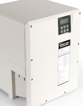
Цифровой гироскопический компас, выполнен как моноблок жестком корпусе из вспененного полиуретана. Имеет панель управления с 4-символьным дисплеем и 6 кнопками управления. При необходимости панель можно снять и расположить в удобном для работы месте. Скорость слежения составляет 100° в секунду. В штатном режиме компас работает от сети 115/230 В АС, при сбое в сети автоматически переключается на питание от аварийного источника 24 В. При сбое питания стабилизация компаса сохраняется в течение 3 минут. Двойные роторы и система жидкостного демпфирования исключает погрешность по широте. Для плавания в морях с частыми штормами разработана модификация 7. Она имеет специальную конструкцию центрующего штифта, которая дает свободу 90° при бортовой и килевой качке.
Технические характеристики:
- Свобода движения при боровой или килевой качке: ±40° (модификация 10), ±90° (модификация 7);
- Напряжение: 24 В постоянного тока и/или 115/230 В переменного тока;
- Рабочие температуры: от -10°C to +55°C;
- Время стабилизации: до 3 часов;
- Скорость отслеживания: 100°/с;
- Дисплей: цифровой с 4 символами;
- Наработка на отказ: 40000 часов;
- Потребляемая мощность: 80 Вт при запуске, 45 Вт при работе, 7 Вт через аналоговый ретранслятор, 5 Вт через цифровой ретранслятор;
- Защита: IP23, IEC/EN 60529;
- Размеры: 404х520х420 мм;
- Вес: 28 кг.
Гирокомпас Navigat X MK1новинка***РМРС***
![]()
- Описание
- Характеристики
NAVIGAT X MK 1 разработан с учетом быстро меняющихся технологий навигационных и управляющих систем XXI века. Первый из этой серии гирокомпас NAVIGAT X MK 1 разработан как компактный моноблок, имеющий небольшой вес и помещенный в корпус из жестко вспененного полиуретана. Это позволяет размещать гирокомпас на любом мостике от крейсерских яхт до наиболее просторных океанских судов. Судовые кабели подсоединяются непосредственно внутри моноблока, что существенно облегчает монтаж. Все электронные компоненты являются вставными модулями, что обеспечивает быстрое и легкое обслуживание. Цифровая информация о направлении получается как абсолютное значение 12-битовой кодировки. Модель NAVIGAT X MK 1 Mod. 10 имеет блок управления с информационным дисплеем, установленным в передней части крышки моноблока. Если требуется, этот блок управления может быть изъят из моноблока и установлен отдельно (например, в интегрированном мостике) на некотором удалении от гирокомпаса. Уникальный метод поддержки гиросферы посредством простой плавучести гарантирует стабилизацию курса в течение коротких сбоев питания. Например, после трех минут сбоя питания ожидаемые отклонения не превысят два градуса. При восстановлении питания, гирокомпас быстро возвратится в меридиан, не требуя обычного периода отработки. Комбинированный эффект использования сдвоенных гироскопов и жидкостной системы подвески, сглаживающей колебания, предотвращает широтную погрешность.
Для работы в чрезвычайно тяжелых морских условиях, где абсолютно необходима высокоточная информация о направлении, рекомендуется модель NAVIGAT X MK 1 Mod. 7, оборудованная специальным контейнером для гиросферы. В этом контейнере установлен уникальный центрующий штифт, удерживающий относительное перемещение гиросферы, установленной в дополнительной системе Карданова подвеса, которая обеспечивает гирокомпасу NAVIGAT X MK 1 Mod. 7 почти неограниченную свободу при бортовой и килевой качке (+90).
Эксплуатационные данные
Линейный способ решения
Погрешность точки < 0.1°
Статическая погрешность <0.1°
Динамическая погрешность < 0.4°
Эксплуатационные данные соответствуют требованиям IMO А. 424 (XI), А. 574 (14), IМ0 82к19) и ISO 8728
Свобода рыскания и качки
SR-180 MK1 Mod. 7 +/- 90°
SR-180 MK1 Mod. 10 +/- 40°
Питание
24 В постоянного тока (от 18 В до 36 В)
115 / 230 В переменного тока +/- 10%
50 Гц / 60 Гц
Гирокомпас включает автоматическое переключение на 24 В при перебое в судовой сети в соответствии с требованиями ГМССБ для INMARSAT / SES терминалов.
Эксплуатационные данные
Диапазон температуры окружающего воздуха
эксплуатация -10° до +55° С
хранение -25°до +70° С
(без поддерживающей жидкости)
Время прихода в меридиан менее 3 часов (0,7°)
Максимальная девиация после прерывания питания на 3 мин.менее 2°
Отслеживание курса более 100° в сек.
Информационный дисплей цифровой четырехзначный
Наличие сигнализации сбоя питания визуальная и звуковая
Наработка на отказ 40 000 часов
Поправка курса:
в типовой комплектации – статическая, ручная или автоматическая
в дополнительной комплектации – динамическая, ручная или автоматическая
Встроенный тест оборудования
ШИНЫ ВЫВОДА ДАННЫХ
NMEA 0183 — 12 выводов — курс по гирокомпасу, курс по магнитному компасу и угол поворота на серийные репитеры и универсальные цифровые репитеры.
NMEA 0183 — 2 вывода — курс по гирокомпасу, курс по магнитному компасу, угол поворота, координаты, скорость.
RS 422 — 3 вывода — курс по гирокомпасу, курс по магнитному компасу, угол поворота, координаты, скорость.
RS 422 FAST — 1 вывод — курс по гирокомпасу, курс по магнитному компасу, угол поворота. RS 422 SUPER FAST 1 вывод — курс по гирокомпасу, курс по магнитному компасу, угла поворота. RS 422 — 1 вывод для регистратора пути направление, положение руля, время, режим управления, скорость, координаты.
6 шагов / — 2 вывода — курса.
внутреннее питание 24 В постоянного тока, 18 Вт. внешнее питание от 12 В до 70 В постоянного тока. Угол поворота -1 вывод по выбору из ± 30° , 90° и 300/мин. ( +/-10 В, 10 мА).
Сигнализация состояния — 1 вывод
Гиро1/Гиро2/Магнитный
Аварийная сигнализация — 1 вывод дежурная сигнализация, сигнализация расхождения с курсом, сигнализация неисправности и сбоя питания.
Стандартный комплект
074807-0000-000 4914-CA Mastercompass NAVIGAT X MK 1, with built-in control and display unit, integrated distribution terminal board
4991-4000 Standard gyro container Mod.10/3 in transport box allowing roll and pitch freedom of + 40°
5000 Gyrosphere type 3 in transport box
4914-3200 Installation kit
| ШИНЫ ВВОДА ДАННЫХ
Координаты 1 ввод NMEA 0183 Скорость 1 ввод NMEA 0183 или 200 импульсов на милю Положение руля 1 ввод аналоговый Постоянная времени 1 ввод с внешнего скорости поворота устройства Курс магнитного компаса 1 ввод синус и косинус из цифрового выхода Электронный компас 1 ввод NMEA0183 Режим управления 1 ввод ручной / авто Соответствует требованиям к защите окружающей среды и ЕМС IEC 945 Морского навигационного оборудования |
|---|
Инструкция Гирокомпас Navigat X MK1 Инструкция — Инструкция Гирокомпас Navigat X MK1 Инструкция — Инструкция гирокомпас Navigat X MK1 Инструкция — Инструкция Navigat X MK1 Инструкция — Инструкция X MK1 Инструкция — Омск Гирокомпас Navigat X MK1 Омск — Омск Гирокомпас Navigat X MK1 Омск — Омск гирокомпас Navigat X MK1 Омск — Омск Navigat X MK1 Омск — Омск X MK1 Омск — Купить Гирокомпас Navigat X MK1 Купить — Купить Гирокомпас Navigat X MK1 Купить — Купить гирокомпас Navigat X MK1 Купить — Купить Navigat X MK1 Купить — Купить X MK1 Купить — Буклет Гирокомпас Navigat X MK1 Буклет — Буклет Гирокомпас Navigat X MK1 Буклет — Буклет гирокомпас Navigat X MK1 Буклет — Буклет Navigat X MK1 Буклет — Буклет X MK1 Буклет — Цена Гирокомпас Navigat X MK1 Цена — Цена Гирокомпас Navigat X MK1 Цена — Цена гирокомпас Navigat X MK1 Цена — Цена Navigat X MK1 Цена — Цена X MK1 Цена в Москве, Санкт-Петербурге, Новосибирске, Екатеринбурге, Нижнем Новгороде, Казани, Челябинске, Омске, Самаре, Ростове-на-Дону, Уфе, Красноярске, Перми, Воронеже, Волгограде, Алма-Ате, Астане, Шымкенте, Караганде, Актобе, Таразе, Павлодаре, Усть-Каменогорске, Семее, Костанае, Атырау, Кызылорде, Уральске, Петропавловске, Актау, Темиртау, Туркестане, Кокшетау, Талдыкоргане, Экибастузе, Рудном или любом другом городе России и Казахстана
Контакты

Аккредитованный партнёр серебрянного уровня Motorola

Авторизованный дилер Vertex Standard на территории Сибирского федерального округа.

Авторизованный сервисный центр и региональный дилер компании Samyung ENC Co., Ltd.

Официальный дилер

Авторизированный дилер

Официальный дилер оборудования радиосвязи стандарта TETRA на территории РФ и стран СНГ

Официальный дилер

Официальный дилер
- Каталог/
- Объекты наблюдения Российского Морского Регистра Судоходства/
- Навигационное оборудование/
- Компасы (магнитные, гирокомпасы, спутниковые )/
- Northrop Grumman Sperry Marine Navigat X Mk 1
Морской гироскопический компас Northrop Grumman Sperry Marine Navigat X Mk 1 одобрен Российским Морским Регистром Судоходства. Navigat X Mk 1 является представителем нового поколения продвинутых морских гироскопических компасов. Применяется как на больших яхтах, так и на коммерческом флоте. Navigat X Mk 1 это высокотехнологичный и легкий компас, выполенный в песпрцедентно компактном и крепком корпусе из пенополиуретана, который может быть установлен практически на любом мостике. Navigat X Mk 1 прост в монтаже и легок в обслуживании благодаря внутреннему типу подключения судовых кабелей и модульной конструкции. Информация о курсе выводится в виде абсолютной величины, получаемой с 13 битного датчика. На лицевой панели корпуса гирокомпаса Navigat X Mk 1 располагается управляющий блок с дисплеем (управляющий блок может быть отсоединен от основной конструкции и установлен в другое место (кабельное соединение)). Благодаря дополнительному карданному подвесу в модификации Mod. 7 гирокомпас Navigat X Mk 1 приспособлен к экплуатации в крайне тяжелых услових, тогда когда точнейшая информация о курсе жизнено важна.
Особенности гирокомпаса Northrop Grumman Sperry Marine Navigat X Mk 1:
- Состоит из одного элемента
- Управляющи блок на лицевой панели
- Прост в установке, легок в обслуживании
- Высокоскоростное слежение за курсом
- Высокоточный цифровой курс
- 7 независимых последоватильных RS 422 и NMEA 0183 выходов
- Соответствует правилам ММО: (A.424(IX), A.694(17), A.821(19))
- Соответствует стандарту ISO 8728
- Само-согласование репитеров
- Без электроснабжения гиросистема остается в меридиан до 3х минут
- Автоматическая система перехода на аварийный источник питания
Спецификации гирокомпаса Northrop Grumman Sperry Marine Navigat X Mk 1:
- Питание: 24 VDC, 115/230 VAC
- Cлежение за курсом: 100°/сек
- Килевая и бортовая качка: ±90°
- Коррекция в настройках: ±180°
- Температура эксплуатации: от -10°С до +55°С
- Холодный пуск (выход в мередиан): ≤ 3 часа (0.7°)
- Пыле/Влагозащищенность: IP23
Скачать:
Брошюра гирокомпаса Northrop Grumman Sperry Marine Navigat X Mk 1
-
Page 1
Digital Gyrocompass Systems Type 4914-CA, Stock No. 74807 and Type 4914-CC, Stock No. 74811 056343/C, 08 May 2008 Northrop Grumman Sperry Marine B.V. (Representative Office) Woltmanstr. 19 • D-20097 • Hamburg, Germany Tel.: +49-40-299 00-0 • Fax: +49-40-299 00-146 • E-mail: service.de@sperry.ngc.com… -
Page 2
NAVIGAT X MK 1 © 2008 Northrop Grumman Sperry Marine B.V. This document and the information herein is the intellectual property of Northrop Grumman Sperry Marine B.V. [NGSM BV] and it’s associate companies and may not be copied or repro- duced without the express permission of NGSM BV. -
Page 3: Safety Instructions
NAVIGAT X MK 1 056343/C Safety Instructions Safety Notice Conventions The following safety notice conventions are followed throughout this manual: A Danger notice contains an operating or main- DANGER tenance procedure, practice, condition, state- ment, etc., which, if not strictly observed, will result in injury or death of personnel.
-
Page 4: General Safety Information For The Operator
WARNING After a power-up from cold, the NAVIGAT X MK 1 requires a settling time of three hours before reliable heading data is available. Power up the system at least three hours before leaving harbour.
-
Page 5: General Safety Information For Service Personnel
CAUTION The NAVIGAT X MK 1 contains electrostatic sensitive components. Electrostatic discharge may permanently damage components. When servicing the NAVIGAT X MK 1, take precautions to prevent elec- trostatic discharge. Avoid touching any of the electronic circuitry. CAUTION It cannot be guaranteed that parameter settings in the User and Setup menus and the entries made in the Magnetic Compass Calibration table are left intact when the software is exchanged.
-
Page 6
056343/C NAVIGAT X MK 1 1-iv… -
Page 7: Table Of Contents
Design and Main Features……………. 1-1 Operating Principle ………………. 1-2 Example System Configurations …………. 1-3 Standalone Gyrocompass/TMC System ……….1-3 Dual NAVIGAT X MK 1 Gyrocompass/TMC System …….. 1-4 Technical Data……………….. 1-5 Chapter 2: Operation Operating Conditions …………….2-1 Display and Operating Keys …………..2-2 Control and Display Unit …………….
-
Page 8
056343/C NAVIGAT X MK 1 Chapter 3: Errors and Alarms Alarm Indication ………………3-1 Audible Alarm Indication …………….3-1 Visual Alarm Indication…………….3-1 Acknowledging Alarms/Muting the Audible Alarm……. 3-2 Alarm Acknowledge ……………… 3-2 Alarm Mute ………………..3-2 Error messages ………………3-3 Service Info Menu (Service Setup 2) ………… -
Page 9
NAVIGAT X MK 1 056343/C Chapter 7: System Configuration Configuration Menu (Service Setup 1)………… 7-1 Setup Access Code………………7-1 Service-Setup 1 – Overview …………..7-2 Service Setup 1 – Parameters …………..7-6 Factory Settings Menu (Technical Pages) ……….7-16 Setup Access Code……………… 7-16 Technical Pages –… -
Page 10
056343/C NAVIGAT X MK 1 viii… -
Page 11: Chapter 1: Introduction
The HSC-version (stock no. 74811) with a specially selected gyrosphere also complies with IMO resolution A.821(19). The rate of turn output of the NAVIGAT X MK 1 complies with IMO reso- lution A.526(13). The NAVIGAT X MK 1 has been type approved by the German Federal…
-
Page 12: Operating Principle
056343/C NAVIGAT X MK 1 1.2 Operating Principle The north-seeking element used in the NAVIGAT X MK 1 system is the gyrosphere, a hermetically sealed unit with a funnel-shaped recess, reaching from the outer skin down to its center. Inside the gyrosphere, two mechanically linked gyroscopes are mounted with their spin axes horizontal in a carrying frame.
-
Page 13: Example System Configurations
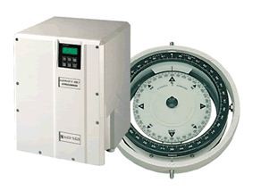
1.3 Example System Configurations Standalone Gyrocompass/TMC System As a standalone system, the NAVIGAT X MK 1 provides North-speed error corrected true heading as well as rate of turn data. If a fluxgate sensor, type 4863, or an electronic magnetic compass is installed, the NAVIGAT X MK 1 applies magnetic variation and distrib- utes magnetic heading data to external equipment (TMC function).
-
Page 14: Dual Navigat X Mk 1 Gyrocompass/Tmc System
The system shown in Figure 1-3 below is the standard configuration for a dual NAVIGAT X MK 1 gyrocompass system. In addition to the two NAVIGAT X MK 1 compasses, this system com- prises the NAVITWIN IV heading management system and the Switch- Over Unit Type 4932.
-
Page 15: Technical Data
NAVIGAT X MK 1 056343/C 1.4 Technical Data Accuracies heading: ≤ 0.1° secant latitude lin. mean settle point error ≤ 0.1° secant latitude static error ≤ 0.4° secant latitude dynamic error deviation after 3 min. power interruption < 2° ≤ 0.5°/minute…
-
Page 16
056343/C NAVIGAT X MK 1 Dimensions and Weight width 404 mm height 520 mm depth 420 mm weight 25 kg approx. Data Inputs ext. gyro heading NMEA 0183 / IEC 61162-1 or PLATH protocol or Lehmkuhl (1200, 2400, 4800 or 9600 Bd.) -
Page 17
NAVIGAT X MK 1 056343/C Data Outputs serial repeater outputs NMEA 0183 (12x TTL) sensor data outputs NMEA 0183 / IEC 61162-1 (4x RS-422; 3 available if AD10 output active) FAST output NMEA 0183 / IEC 61162-1 (1x RS-422) or PLATH protocol… -
Page 18
056343/C NAVIGAT X MK 1 Technical Data… -
Page 19: Chapter 2: Operation
The supporting fluid in the gyrosphere container will start freezing at temperatures below 0 °C. The NAVIGAT X MK 1 may no longer be operated when the ambient tem- perature at the gyrocompass’ location falls below –10 °C while the com- pass is in operation or when the ambient temperature falls below 0 °C…
-
Page 20: Display And Operating Keys
056343/C NAVIGAT X MK 1 2.2 Display and Operating Keys Control and Display Unit Figure 2-1: NAVIGAT X MK 1 control and display unit ÿÿÿÿÿÿÿÿÿÿÿÿÿÿÿÿÿÿÿÿ ÿÿÿÿÿÿÿÿÿÿÿÿÿÿÿÿÿÿÿÿ ÿÿÿÿÿÿÿÿÿÿÿÿÿÿÿÿÿÿÿÿ ÿÿÿÿÿÿÿÿÿÿÿÿÿÿÿÿÿÿÿÿ Display ➀ LCD Display: 4×20 character text display In normal operational mode, shows the available heading sources and the heading diff.
-
Page 21: External Control Devices
(apply a 180° offset to the heading data), e.g. for operation in double- ended ferries. • The audible alarm at the NAVIGAT X MK 1 the may be muted from a remote device, e.g. a central alarm panel. External control devices…
-
Page 22: Power-Up Sequence
056343/C NAVIGAT X MK 1 2.4 Power-up Sequence The NAVIGAT X MK 1 is not equipped with a power switch. The gyro- compass powers up as soon as supply power is applied. Upon power up, the startup routine is executed:…
-
Page 23: Selecting The Active Heading Source
WARNING Make sure that the NAVIGAT X MK 1 has settled before using its heading as the reference for heading control systems, RADAR, ECDIS, etc. A magnetic heading source should be made active only in case of failure of the gyrocompass(es).
-
Page 24: Optional Functions
A remotely muted alarm remains in the pending (unacknowledged) state. The alarm message is shown on the display until the alarm is acknowl- edged at the NAVIGAT X MK 1 or the cause of the alarm is eliminated. Reversing the Heading Display (180° offset) To reverse the heading display, e.g.
-
Page 25: Operating Menu
F1 DISPLAY DATA F2 MANUAL SETTINGS F3 SETUP MENU The NAVIGAT X MK 1 returns to nor- mal operational mode. Navigating the Menu In the menu mode, the operator may navigate through the menu using the F1, F2, F3, Up/Down, Dim+/Dim- and MENU key functions.
-
Page 26: Selecting Parameter Settings
056343/C NAVIGAT X MK 1 Selecting Parameter Settings A number of operational and setup parameters are set by selecting the appropriate option from a list. Flashing up/down arrow symbols to the right of a parameter setting indicate that a selection can be made from a list of options: With the Up/Down keys, select the required MAN.SETTINGS…
-
Page 27: Selecting A Display Data Page
NAVIGAT X MK 1 056343/C 2.9 Selecting a Display Data Page The Display Data menu allows the operator to select one out of five pages to permanently display relevant operational data, instead of the normal heading display screen. The selected page is displayed until another page is selected or the Dis- play Data mode is quit.
-
Page 28: Manual Settings Menu
In case a NAVITWIN compass monitor / heading management system is installed, the manual settings must be entered at the NAVITWIN. The NAVITWIN will overwrite any manual settings entered locally at the NAVIGAT X MK 1 control and display unit. Manual Settings – Overview Figure 2-2: MAN.SETTINGS GYRO 1…
-
Page 29
NAVIGAT X MK 1 056343/C Figure 2-3: contd. from previous page Manual Settings (cont.d) MAN.SETTINGS GYRO 1û F1 NORTH SP.ERR.CORR north speed error correction NORTH SP. ERR. CORR F2 SET. NAVIPRINT F3 SETTINGS ROT ü nav. data printer settings SET. NAVIPRINT NAVIPRINT PAP. -
Page 30: Manual Settings — Parameters
056343/C NAVIGAT X MK 1 Manual Settings – Parameters Speed/Latitude Speed/Lat Mode Selects the speed and position input modes. Speed Mode Selects the speed input mode. Settings: AUTO Speed data is read automatically from the serial data or the 200 pulse/nm input…
-
Page 31
NAVIGAT X MK 1 056343/C Hdg. Diff. Alarm Sets the manual input values for the speed and latitude. Between Selects the heading sources to monitor. Settings: GY1/GY2 Monitor difference between gyros 1 and 2 GY1/MAG Monitor difference between gyro 1 and magnetic hdg. -
Page 32
056343/C NAVIGAT X MK 1 Set. NAVIPRINT Sets the operating parameters for the NAVIPRINT nav. data printer. NAVIPRINT Turns printing on and off. Settings: Activate output to printer No output to printer Pap. speed Sets the paper feed speed. Settings: 60 mm print at 60 mm/h (1 cm = 10 min.). -
Page 33
NAVIGAT X MK 1 056343/C Settings ROT Sets the rate of turn input parameters. Time constant ROT Sets the damping time constant for the analogue rate of turn output. The larger the time constant, the less short-time fluctuations will be present in the analogue rate of turn output voltage. -
Page 34: User Setup
056343/C NAVIGAT X MK 1 2.11 User Setup The User Setup menu provides access to settings which the operator may need to alter occasionally. User Setup – Overview Figure 2-4: USER SETUP User Setup F1 DATE/TIME DATE/TIME input date/time F2 SOFTWARE VERSION F3 MAG.C.
-
Page 35: User Setup — Parameters
NAVIGAT X MK 1 056343/C User Setup – Parameters Date & Time Sets the date and time input parameters. Mode Selects the date and time input mode. Settings: AUTO Date/time are read automatically from the serial data input The current date and time are entered manually Man.
-
Page 36
056343/C NAVIGAT X MK 1 2-18 User Setup… -
Page 37: Chapter 3: Errors And Alarms
NAVIGAT X MK 1 056343/C Chapter 3: Errors and Alarms 3.1 Alarm Indication Audible Alarm Indication Single Beep: Invalid Action A single short beep indicates that the operator attempted to carry out an invalid action. This is the case, e.g. if the operator tries to change the heading reference in an automatic steering mode or to activate a head- ing source from which no valid data is received.
-
Page 38: Acknowledging Alarms/Muting The Audible Alarm
When the cause of an alarm is eliminated, the alarm is acknowledged automatically and the alarm status is cleared. The NAVIGAT X MK 1 does not keep a history of past (inactive) alarms. Alarm Mute To mute the audible alarm at the NAVIGAT X MK 1: Press Shift-Reset.
-
Page 39: Error Messages
NAVIGAT X MK 1 056343/C 3.3 Error messages The following table lists the error messages which may appear on the display and in the error list when a system alarm is active. Table 3-1: Message on Message in Cause Corrective…
-
Page 40
056343/C NAVIGAT X MK 1 Message on Message in Cause Corrective Display Error List Action POSITION FAILURE POS. Loss of position Check position ERROR data from ext. data source and source. interface. HEADING HEAD. DIFF The monitored Check heading DIFF . ALARM… -
Page 41: Service Info Menu (Service Setup 2)
NAVIGAT X MK 1 056343/C 3.4 Service Info Menu (Service Setup 2) The Service Setup 2 provides access to system status information which is used during installation and for troubleshooting errors. Furthermore, an option is provided to reset the system without cycling the power (warm start).
-
Page 42: Service Setup 2 — Overview
056343/C NAVIGAT X MK 1 Service Setup 2 – Overview Figure 3-2: SERVICE SETUP 2 Service Setup 2 F1 GYROSPHERE DATA GYROSPHERE DATA gyrosphere operational data F2 OP.TIME COUNTER F3 DATA LIST ü TEMPERATURE: gyrosphere ambient temperature PH. BRIDGE: phase bridge voltage GYRO CURR.: gyrosphere current…
-
Page 43: Service Setup 2 — Parameters
NAVIGAT X MK 1 056343/C Service Setup 2 – Parameters Gyrosphere Data Displays the gyrosphere operating data. Displays: Temperature The ambient temperature around the gyrosphere container. Ph. Bridge The follow-up circuit phase bridge voltage. Gyro Curr. The gyrosphere current. Op. Time Counter Displays the gyrosphere operation time counter.
-
Page 44
056343/C NAVIGAT X MK 1 Service Info Menu (Service Setup 2) -
Page 45: Chapter 4: Scheduled Maintenance
Use only water and soap or a mild detergent to clean the compass. 4.2 Gyrosphere Maintenance Specifications The gyrosphere is the only component of the NAVIGAT X MK 1 which requires regular maintenance. CAUTION Scheduled maintenance or service work on the gyrosphere is to be car- ried out by authorized service personnel only.
-
Page 46: Five-Year Maintenance
056343/C NAVIGAT X MK 1 Five-Year Maintenance To ensure continued trouble-free operation and to minimize the risk of failure, Sperry Marine recommends that every five years, the gyro- sphere and the centring pin are exchanged by authorized service per- sonnel.
-
Page 47: Chapter 5: Preventive Maintenance
The supporting fluid in the gyrosphere container will start freezing at temperatures below 0 °C. The NAVIGAT X MK 1 may no longer be operated when the ambient tem- perature at the gyrocompass’ location falls below –10 °C while the com- pass is in operation or when the ambient temperature falls below 0 °C…
-
Page 48: Removing The Container From The Compass Housing
056343/C NAVIGAT X MK 1 Removing the container from the compass housing DANGER When the compass is energized, the gyrosphere operating voltage of 100 VAC @ 337 Hz is present on the master PCB, the gyrosphere supply lines, and across the gyrosphere contacts.
-
Page 49
NAVIGAT X MK 1 056343/C 4. Turn the bellows, until the largest of the three coupling seats in the bayonet collar points towards the front of the housing. The seat is marked by a green dot on the collar. 5. Put both hands around the con-… -
Page 50: Re-Installing The Container In The Compass Housing
056343/C NAVIGAT X MK 1 Re-installing the container in the compass housing DANGER When the compass is energized, the gyrosphere operating voltage of 100 VAC @ 337 Hz is present on the master PCB, the gyrosphere supply lines and across the gyrosphere contacts.
-
Page 51
NAVIGAT X MK 1 056343/C 8. Gently lower the container. The coupling tongues engage into their seats in the bayonet and the con- tainer locks in place by its own weight. 9. Plug the gyrosphere supply and pickoff connector into its socket on the gyrosphere container. -
Page 52: Procedure
056343/C NAVIGAT X MK 1 Power-up function test To verify the correct operation of the re-installed gyrosphere, the settling behaviour of the compass is to be observed. DANGER When the compass is energized, the gyrosphere operating voltage of 100 VAC @ 337 Hz is present on the master PCB, the gyrosphere supply lines and across the gyrosphere contacts.
-
Page 53
NAVIGAT X MK 1 056343/C 3. During the settling phase, periodically call up the gyrosphere data sub-menu from the Service Setup 2 (code 610), to observe the gyro- sphere current: Directly after power-up, the gyro- GYROSHPERE DATA sphere current should not exceed TEMPERATURE 42 °C… -
Page 54
056343/C NAVIGAT X MK 1 Protecting the Gyrosphere from Low Temperatures… -
Page 55: Chapter 6: Installation
NAVIGAT X MK 1 056343/C Chapter 6: Installation 6.1 Mechanical Installation The NAVIGAT X MK 1 gyrocompass system comprises the compass housing complete with installed base plate assembly and master PCB, the gyrosphere container, the gyrosphere and the installation and replacement parts kit.
-
Page 56: Electrical Installation
The NAVIGAT X MK 1 is delivered prewired for connection to 230VAC. A wire link connects transformer terminal 5 to terminal 6. If the system is required to operate on 115 VAC, wire links must be installed to link terminal 4 to terminal 6 and terminal 5 to terminal 7.
-
Page 57: Gyrosphere Installation
NAVIGAT X MK 1 056343/C If installation-specific connection diagrams have been provided for a given system, these supersede any connection information contained in standard connection diagrams. Ship’s cables are directly connected to screw-down terminals on the master PCB. Insert the ship’s cables through the inlets at the sides of the compass housing.
-
Page 58: Initial System Configuration
Man- ual Settings menu. If a magnetic heading source is connected to the NAVIGAT X MK 1, the magnetic compass calibration procedure should be carried out during a sea trial, as described under «Magnetic Compass Calibration» below6.5.
-
Page 59
NAVIGAT X MK 1 056343/C To finalize the installation: 1. Set the operational parameters the Manual Settings menu to suita- ble values. Wherever possible, automatic data input should be selected in preference of manual input. 2. Enter the current date and time in the User Setup menu. -
Page 60: Alignment Error Correction
056343/C NAVIGAT X MK 1 6.5 Alignment Error Correction In order to obtain correct heading data, the existing alignment error (i.e. the angular difference between the compass orientation and the vessel’s fore-and-aft axis) must be determined and the required correction applied.
-
Page 61: Magnetic Compass Calibration
If magnetic heading is received from an already calibrated source, such as a NAVITWIN, NAVIPILOT or a self-calibrating electronic compass, cal- ibration at the NAVIGAT X MK 1 is not required and must be disabled. CAUTION The magnetic heading calibration corrects deviations due to the com- bined effects of the magnetic environment, the particular sensor being used and the receiving circuitry on the master PCB.
-
Page 62
F3 MAGN.C. 270.9° DIFF G1/G2 5°ü magnetic heading values shown on the NAVIGAT X MK 1 display. At every full 10° of steering magnetic compass heading (0°, 10°, … , 350°), note the display value. Mag. HDG 6. -
Page 63
NAVIGAT X MK 1 056343/C Storing the magnetic heading calibration table 1. Call up the User Setup and go to the ’Magn Cal Tab’ sub-menu. Press Shift-F1. (’enter values’) The calibration table entry sub-menu is shown. 2. To enter the previously determined correction values:… -
Page 64
056343/C NAVIGAT X MK 1 6-10 Alignment Error Correction… -
Page 65: Chapter 7: System Configuration
7.1 Configuration Menu (Service Setup 1) The Service Setup 1 provides access to the system parameters which configure the NAVIGAT X MK 1 according to the requirements of the installation at hand. The Service Setup 1 also provides a test mode to check the proper func- tion of the serial and 6 step/°…
-
Page 66: Service-Setup 1 — Overview
056343/C NAVIGAT X MK 1 Service-Setup 1 – Overview Figure 7-1: SERVICE SETUP 1 Service Setup 1 F1 INTERFACE I/O INTERFACE I/O interface configuration F2 ANALOG ROT OUTP. F3 FEEDBACK SIGNALü GYRO INPUT PLATH LEHMK. 1200 LEHMK. 2400 LEHMK. 4800 LEHMK.
-
Page 67
NAVIGAT X MK 1 056343/C Figure 7-2: contd. from previous page Service Setup 1 (contd.) SERVICE SETUP 1 F1 INTERFACE I/O F2 ANALOG ROT OUTP. ANALOG ROT OUTP. settings analog ROT output F3 FEEDBACK SIGNALü sc. factor: 0.1 – 999.9 mV/°/min zero offset: -999 –… -
Page 68
056343/C NAVIGAT X MK 1 Figure 7-3: contd. from previous page Service Setup 1 (contd.) SERVICE SETUP 1 û F1 EXT. STATUS IN EXT. STATUS IN ext. status input function F2 NAME OF GYRO F3 TEST MODE ü STATUS IN STAT. -
Page 69
NAVIGAT X MK 1 056343/C Figure 7-4: contd. from previous page Service Setup 1 (contd.) SERVICE SETUP 1 û F1 K1 MUTE/HDG-DIFF K1 MUTE/HDG-DIFF alarm relay K1 functionality F2 SPEED FILTER HDG-DIFF MUTE SPEED FILTER speed filter settings for error correction t. -
Page 70: Service Setup 1 — Parameters
056343/C NAVIGAT X MK 1 Service Setup 1 – Parameters Interface I/O Configures the in- and output interfaces. Gyro Input Selects the interface protocol for the ext. Gyro input. Settings: PLATH The input reads the PLATH binary data protocol LEHMK. 1200 The input is reads the Lehmkuhl (Scandinavian Microsys- tems) protocol at 1200 Bd.
-
Page 71
NAVIGAT X MK 1 056343/C Mag Hdg. Inp. Configures the magnetic heading input. Settings: SIN COS The input reads analogue voltages from a Sperry Marine fluxgate sensor type 4863 at the analogue fluxgate interface NMEA-HDM The input reads the NMEA $—HDM sentence at the NMEA magn. -
Page 72
056343/C NAVIGAT X MK 1 Sens. D. M. Outp. Selects the output sentence format for magnetic heading at the sensor data outputs Settings: NMEA-HCHDM Magnetic heading is sent using the NMEA $—HDM sentence with talker ID “HC” NMEA-HCHDT Magnetic heading is sent using the NMEA $—HDT sentence with talker ID “HC”… -
Page 73
NAVIGAT X MK 1 056343/C NMEA SuperFAST Configures the SuperFAST serial data output. Settings: 4800 Baud The output transmits all available data in NMEA format at 4800 Bd. (standard according to IEC 61162-1) 9600 Baud The output transmits all available data in NMEA format at 9600 Bd. -
Page 74
056343/C NAVIGAT X MK 1 Analog ROT Outp. Configures the analogue rate of turn output. Sc. Factor Sets the scaling for the output. Value: 0.1 – 999.9 mV/°/min. Zero Offset Sets the zero-point offset for the output. Value: -999 – 999 mV Feedback Signal Configures the rudder angle feedback inputs. -
Page 75
NAVIGAT X MK 1 056343/C System Type Configures the system type and the heading selector device. System Sets the system configuration Settings: Single gyrocompass system: the control and display unit shows own gyro heading only; the heading source selection and heading difference alarm functions are not available. -
Page 76
056343/C NAVIGAT X MK 1 Align Err. Corr. Sets the alignment error correction value Settings: -179.9 – +180.0 ° Shaft Cor. Angle Sets the shaft encoder correction value Settings: -179.9 – +180.0 ° Ext. Status In Configures the external status signal input port… -
Page 77
NAVIGAT X MK 1 056343/C Name Of Gyro Sets the compass ID. Settings: Standalone single gyro or main gyro in multiple gyrocom- pass system. Backup gyro in a dual or triple gyrocompass system. Backup gyro in a triple gyrocompass system. -
Page 78
056343/C NAVIGAT X MK 1 Gen. Alarm Setup Selects in which cases the “General Alarm” relay is actuated. Settings: On all alarms The relay is actuated whenever an alarm condition exists. On fatal alarms The relay is actuated only in case of fatal alarms. A fatal alarm exists when the gyrocompass can no longer provide its own heading data. -
Page 79
When this option is selected, relay K1 is actuated whenever an alarm is acknowledged or muted locally at the NAVIGAT X MK 1. In multicompass systems which also require a heading dif- ference alarm output, a separate compass monitoring device, such as the NAVITWIN IV, must provide the heading difference alarm. -
Page 80: Factory Settings Menu (Technical
056343/C NAVIGAT X MK 1 7.2 Factory Settings Menu (Technical Pages) The Technical Pages provide access to a number of factory-set parame- ters which need not normally be altered. However, should the system software need to be exchanged, these settings will be lost and must be re-entered manually.
-
Page 81: Technical Pages- Parameters
NAVIGAT X MK 1 056343/C Technical Pages– Parameters Software Version Displays detailed hard- and software version information. Settings: Hardware The revision code of the master PCB. SW Ver. The creation date of the system software. Masterboard The version code of the system software.
-
Page 82
056343/C NAVIGAT X MK 1 7-18 Factory Settings Menu (Technical Pages) -
Page 83: Chapter 8: Troubleshooting
Chapter 8: Troubleshooting 8.1 Troubleshooting Instructions The NAVIGAT X Mk 1 is a complex electronic system. In case of malfunc- tion, it would neither be practical nor economical to carry out trouble- shooting and servicing in the field down to the level of individual circuit components.
-
Page 84: Location Of Parts On The Master Pcb
056343/C NAVIGAT X MK 1 8.2 Location of Parts on the Master PCB Figure 8-1 below shows the locations of exchangeable components, connectors, trimpots and diagnostic LED indicators on the master PCB. Figure 8-1: TB 7 TB 6 TB 5…
-
Page 85: Exchangeable Components
NAVIGAT X MK 1 056343/C Exchangeable Components Table 8-1: Part Function Stock No. Exchangeable compo- IC 5 quad RS-422 output driver IC; 046485-0000-000 nents on the master drives Sensor Data TB 7.1/7.2 and 7.3/7.4, Compass Monitor, Display units IC 6 quad RS-422 output driver IC;…
-
Page 86: Test Resistor / Trimpots
Diagnostic LEDs As an aid in troubleshooting, a number of diagnostic LED indicators are provided on the NAVIGAT X MK 1 PCB. These indicate the presence of supply voltages, activities on the serial data I/O lines and the current states of the status I/O ports.
-
Page 87
NAVIGAT X MK 1 056343/C Colour Indication CR 30 green activity on Tx line, Sens. Data or AD10 clock, TB 7.13/7.14 CR 31 green activity on Tx line, SuperFast or AD10 data, TB 7.11/7.12 CR 32 overload 24VDC out to Switch-Over Unit, TB 3.22… -
Page 88
056343/C NAVIGAT X MK 1 Colour Indication CR 105 overload 24VDC out to repeater 10 CR 106 overload 24VDC out to repeater 11 CR 110 green activity on Rx line, ext. Gyro, TB 4.1/4.2 CR 111 green activity on Rx line, Magnetic Heading, TB 4.17/4.18… -
Page 89: Chapter 9: Corrective Maintenance
NAVIGAT X MK 1 056343/C Chapter 9: Corrective Maintenance The NAVIGAT X MK 1 is generally not field-serviceable on the compo- nent level. In case of malfunction, complete sub-assemblies must be exchanged and the defective sub-assemblies returned to Sperry Marine.
-
Page 90: Replacing Socketed Ics
056343/C NAVIGAT X MK 1 Exchanging the flash-memory IC Note The flash-memory IC is a 32-pin PLCC chip. A suitable extractor tool is required to remove the IC from its socket. Verify that a new flash-memory IC, stock no. 26562, containing software 4914-1090-00 with the required revision identifier and release date has been obtained.
-
Page 91: Appendix
4914-0125-03 Table Note After installation of the NAVIGAT X MK 1, please return a filled-out copy of the Setup Table to Sperry Marine for inclusion in the ship’s file. When permanent changes are made to the system configuration, please return an updated copy of the Setup Table to Sperry Marine.
-
Page 92
056343/C NAVIGAT X MK 1… -
Page 93
Time Const. ROT: Max. Value ROT: Time Constant: Max. Value: °/min. User Setup Date and Time Mode AUTO Mag. Comp. Cal. Table Northrop Grumman Sperry Marine B.V. (Representative Office) Woltmanstr. 19, D-20097 Hamburg, Germany Tel.: +49-40-299 00-0, Fax: +49-40-299 00-298, E-mail: service.de@sperry.ngc.com… -
Page 95
Date / Signature: Note After installation of the NAVIGAT X MK 1, please return a filled-out copy of the Setup Table to Sperry Marine for inclusion in the ship’s file. When permanent changes are made to the system configuration, please return an updated copy of the Setup Table to Sperry Marine. -
Page 97
Correction values are specific to the master PCB installed. When exchanging a master PCB, read out the correction values and update this setup table to reflect the new values. Northrop Grumman Sperry Marine B.V. (Representative Office) Woltmanstr. 19, D-20097 Hamburg, Germany Tel.: +49-40-299 00-0, Fax: +49-40-299 00-298, E-mail: service.de@sperry.ngc.com… -
Page 99
80.0 260.0 90.0 270.0 100.0 280.0 110.0 290.0 120.0 300.0 130.0 310.0 140.0 320.0 150.0 330.0 160.0 340.0 170.0 350.0 Northrop Grumman Sperry Marine B.V. (Representative Office) Woltmanstr. 19, D-20097 Hamburg, Germany Tel.: +49-40-299 00-0, Fax: +49-40-299 00-298, E-mail: service.de@sperry.ngc.com…