- Manuals
- Brands
- Genie Manuals
- Boom Lifts
- GS-3246
Manuals and User Guides for Genie GS-3246. We have 14 Genie GS-3246 manuals available for free PDF download: Service And Repair Manual, Service Manual, Maintenance Manual, Operator’s Manual

Genie GS-3246 Service And Repair Manual (343 pages)
Scissor Lifts
Brand: Genie
|
Category: Lifting Systems
|
Size: 19.04 MB
Table of Contents
-
Introduction
2
-
Find a Manual for this Model
2
-
Serial Number Range
3
-
Revision History
4
-
Serial Number Legend
6
-
-
Safety Rules
7
-
Table of Contents
9
-
April
12
-
Gs-1530 / Gs
14
-
-
Specifications
17
-
Machine Specifications
17
-
Gs-30 • Gs-32 • Gs-46 • Gs
17
-
April
18
-
-
Performance Specifications (Models Without Proportional Lift Function)
19
-
April
19
-
Gs-30 • Gs-32 • Gs-46 • Gs
20
-
-
Performance Specifications (Models with Proportional Lift)
21
-
Hydraulic Oil Specifications
23
-
Hydraulic Component Specifications
26
-
Manifold Component Specifications
27
-
Hydraulic Hose and Fitting Torque Specifications
28
-
Torque Procedure
29
-
-
Repair Procedures
31
-
Introduction
31
-
-
Platform Controls
33
-
Circuit Board
35
-
Joystick
36
-
Platfrom Controls Alarm
36
-
Platform Emergency Stop Button
37
-
-
Ground Controls
38
-
Software Revision Level
39
-
Machine Setup
40
-
Loading or Updating Machine Software
41
-
Using a Wi-Fi Router to Connect to the Smartlink Web Service Tool
46
-
Service Override Mode
48
-
Level Sensors
50
-
Manual Platform Lowering Cable
65
-
Outrigger Calibration
67
-
-
Hydraulic Tank
68
-
Hydraulic Pump
69
-
How to Remove the Hydraulic Pump
70
-
-
Manifolds
72
-
Function Manifold Components — GS-1530, GS-1532, GS-1930 and GS-1932
72
-
Function Manifold Components — GS-2032, GS-2632, GS-3232, GS-2046, GS-2646 and GS-3246
74
-
Function Manifold Components — GS-4047
76
-
Check Valve Manifold Components — GS-1530, GS-1532, GS-1930 and GS-1932
78
-
Lift Pressure Selector Manifold Components — GS-4047
79
-
Outrigger Function Manifold Components — GS-3232
80
-
Outrigger Cylinder Manifold Components — GS-3232
81
-
Valve Adjustments — Function Manifold
82
-
Valve Coils
88
-
-
Steer Axle Components
90
-
Yoke and Drive Motor
90
-
Steer Cylinder
91
-
Steer Bellcrank
92
-
-
Non-Steer Axle Components
93
-
Drive Brake
93
-
-
Brake Release Hand Pump Components
94
-
Scissor Components
95
-
Scissor Assembly, GS-1530 and GS-1532
96
-
Scissor Assembly, GS-1930 and GS-1932
102
-
Scissor Assembly, GS-2032 and GS-2046
110
-
Scissor Assembly, GS-2632 and GS-2646
117
-
Scissor Assembly, GS-3232 and GS-3246
125
-
Scissor Assembly, GS-4047
134
-
Scissor Arm Wear Pads
142
-
Platform Height Sensor
144
-
Lift Cylinder
146
-
Pressure Transducer
157
-
Platform Overload System
159
-
Platform Overload Recovery
164
-
-
Platform Components
166
-
Platform
166
-
Platform Extension Deck
167
-
-
Battery Charger
168
-
Selecting a Charge Profile
169
-
-
Diagnostics
171
-
Introduction
171
-
GCON I/O Map Without Load Sense (All Machines Except GS-3232)
174
-
GCON I/O Map with Load Sense (All Machines Except GS-3232)
175
-
GCON I/O Map Without Load Sense GS-3232 Only)
176
-
GCON I/O Map with Load Sense (GS-3232 Only)
178
-
Operation Indicator Codes (OIC)
180
-
Diagnostic Trouble Codes (DTC)
180
-
Troubleshooting «HXXX» and «PXXX» Faults
181
-
Fault Inspection Procedure
182
-
Type «HXXX» Faults
184
-
Type «PXXX» Faults
188
-
Type «UXXX» Faults
189
-
Type «FXXX» Faults
192
-
Type «CXXX» Faults
195
-
Battery Charger
197
-
Charger Fault Codes
198
-
Charger Error Codes
199
-
-
-
Schematics
203
-
Introduction
203
-
Electrical Component and Wire Color Legends
204
-
Wiring Diagram Ground and Platform Controls
206
-
Limit Switch Legend
207
-
Electrical Symbol Legend
208
-
Hydraulic Symbols Legend
209
-
-
Hydraulic Schematics
210
-
Hydraulic Component Reference Legend
210
-
Hydraulic Component Abbreviation Legend
211
-
Hydraulic Schematic, GS-1530, 1532, 1930, 1932 (from Serial Number GS3010A-110000, GS3011C-10000, GS3014D-101, GS3016P-142281)
212
-
GS3212C-10000 to GS3214C-11873, GS4612A-110000 to
213
-
-
Hydraulic Schematic, GS-2032, 2632, 3232, 2046, 2646, 3246
214
-
Hydraulic Schematic, GS-2032, 2632, 3232, 2046, 2646, 3246 (from Serial Number GS3214A-119071, GS3214C-11874
214
-
Hydraulic Schematic, GS-3232 (from Serial Number GS3211A-110000, GS3212C-10000, GS3216P-142677)
215
-
Hydraulic Schematic, GS-4047 (from Serial Number GS4712C-101 to GS4714C-1459)
216
-
Hydraulic Schematic, GS-4047
216
-
(From Serial Number GS4714C-1460, GS4714D-101, GS4716P-101)
217
-
(From Serial Number GS3010A-110000 to GS3011A-110827)
220
-
-
-
Electrical Schematics — ANSI / CSA Models
220
-
Electrical Schematic, GS-1530 / GS-1930, ANSI / CSA (from Serial Number GS3011A-110828 to GS3014A-136972, GS3014D-101 to GS3015D-1113)
224
-
Electrical Schematic, GS-1530 / GS-1930
224
-
GS3016P-142281 to GS3016P-158208)
228
-
-
Electrical Schematic, GS-1530/1930, ANSI/CSA
231
-
Electrical Schematic, GS-3232, ANSI / CSA
233
-
(From Serial Number GS3211A-110000 to GS3214A-135714)
234
-
-
Electrical Schematic, GS-3232, ANSI / CSA
234
-
(From Serial Number GS3214A-135715 to GS3215A-141898)
238
-
-
Electrical Schematic, GS-3232, ANSI / CSA (from Serial Number GS3215A-141899, GS3216P-142677 to GS3216P-146462)
242
-
Electrical Schematic, GS-2032, 2632, 2046, 2646, ANSI / CSA
249
-
GS4612A-110000 to GS4614A-135366, GS4613D-101 to GS4615D-1303)
250
-
-
Electrical Schematic, GS-2032, 2632, 2046, 2646, ANSI/CSA
250
-
GS4614A-135367 to GS4615A-137959, GS4615D-1304)
254
-
-
Electrical Schematic, GS-2032, 2632, 2046, 2646, ANSI / CSA (from Serial Number GS3216P-146463, GS4616D-4433, GS4616P-139711)
262
-
Electrical Schematic, GS-3246, GS4047 ANSI / CSA (from Serial Numbers GS4616D-4433, GS4616P-139711, GS4716D-3102, GS4716P-101)
272
-
-
Electrical Schematics — CE and Australia Models
273
-
Electrical Schematic GS-1530, 1532, 1930, 1932, (from Serial Number GS3010A-110000 to GS3011A-110827) as / CE
274
-
Electrical Schematic, GS-1530/32_GS-1930/32 (from Serial Number GS3011A-110828 to GS3014A-136972, GS3011C-10000 to
278
-
Electrical Schematic, GS-1530, 1532, 1930, 1932, AS/CE
282
-
GS3015D-1114 to GS3016D-5426, GS3016P-142281 to GS3016P-158208)
282
-
-
Electrical Schematic, GS-1530, 1532, 1930, 1932, AS/CE
286
-
(From Serial Numbers GS3015D-5427, GS3016P-158209)
286
-
-
Electrical Schematic, GS-3232, as / CE
288
-
Gs3215C-14503)
288
-
-
Electrical Schematic, GS-3232, as / CE (from Serial Number GS3214A-135715 to GS3215A-141898, GS3215C-14504)
292
-
Electrical Schematic, GS-3232, as / CE (from Serial Numbers GS3215A-141899, GS3216P-142676 to GS3216P-146462)
296
-
Electrical Schematic, GS-3232, CE / as (from Serial Number GS3216P-146463)
300
-
Electrical Schematic, GS-2032, 2632, 2046, 2646, as / CE
303
-
GS4613D-101 to GS4615D-1303)
304
-
-
Electrical Schematic, GS-2032, 2632, 2046, 2646, AS/CE
308
-
GS3215C-14378, GS4614A-135367 to GS4615A-137959, GS4615C-14504, GS4615D-1304)
308
-
-
Electrical Schematic, GS-2032, 2632, 2046, 2646, as / CE
312
-
GS3216P-146462, GS4615A-137960, GS4616P-138362 to
312
-
-
Electrical Schematic, GS-2032, 2632, 2046, 2646, as / CE (from Serial Numbers GS3216P-146463, GS4616P-139711)
316
-
Electrical Schematic, GS-3246, as / CE
318
-
Electrical Schematic, GS-3246, as / CE
322
-
Electrical Schematic, GS-3246, as / CE
326
-
GS4615A-137960, GS4616P-138362 GS4616P to GS4616P-139710)
326
-
-
Electrical Schematic, GS-3246, as / CE (from Serial Number GS4616D-4433, GS4616P-139711)
330
-
Electrical Schematic, GS-4047, as / CE
332
-
GS4712C-101 to GS4715C-2130, GS4714D-101 to GS4715D-749)
332
-
-
Electrical Schematic, GS-4047, as / CE (from Serial Number GS4715C-2131, GS4715D-750 to GS4716D-3101)
336
-
Electrical Schematic, GS-4047, as / CE (from Serial Number GS4716D-3102)
340
-
Advertisement

Genie GS-3246 Service And Repair Manual (335 pages)
Scissor lifts
Brand: Genie
|
Category: Boom Lifts
|
Size: 17.47 MB
Table of Contents
-
Find a Manual for this Model
2
-
Serial Number Range
3
-
Revision History
4
-
Serial Number Legend
5
-
Safety Rules
6
-
Table of Contents
8
-
-
Specifications
17
-
Machine Specifications
17
-
Performance Specifications (Models Without Proportional Lift Function)
19
-
Performance Specifications (Models with Proportional Lift)
21
-
Hydraulic Specification
23
-
Hydraulic Component Specifications
26
-
Manifold Component Specifications
27
-
Hydraulic Hose and Fitting Torque Specifications
28
-
Torque Procedure
29
-
-
Repair Procedures
31
-
Introduction
31
-
-
Platform Controls
33
-
Circuit Board
35
-
Joystick
36
-
Platfrom Controls Alarm
36
-
Platform Emergency Stop Button
37
-
-
Ground Controls
38
-
Software Revision Level
39
-
Machine Setup
40
-
Loading or Updating Machine Software
41
-
Using a Wi-Fi Router to Connect to the Smartlink Web Service Tool
46
-
Service Override Mode
48
-
Level Sensors
50
-
Manual Platform Lowering Cable
65
-
Outrigger Calibration
67
-
-
Hydraulic Tank
68
-
Hydraulic Pump
69
-
Function Pump
69
-
How to Remove the Hydraulic Pump
70
-
-
Manifolds
72
-
Function Manifold Components — GS-1530, GS-1532, GS-1930 and GS-1932
72
-
Function Manifold Components — GS-2032, GS-2632, GS-3232, GS-2046, GS-2646 and GS-3246
74
-
Function Manifold Components — GS-4047
76
-
Check Valve Manifold Components — GS-1530, GS-1532, GS-1930 and GS-1932
78
-
Lift Pressure Selector Manifold Components — GS-4047
79
-
Outrigger Function Manifold Components — GS-3232
80
-
Outrigger Cylinder Manifold Components — GS-3232
81
-
Valve Adjustments — Function Manifold
82
-
Valve Coils
88
-
-
Steer Axle Components
90
-
Yoke and Drive Motor
90
-
Steer Cylinder
91
-
Steer Bellcrank
92
-
-
Non-Steer Axle Components
93
-
Drive Brake
93
-
-
Brake Release Hand Pump Components
94
-
Scissor Components
95
-
Scissor Assembly, GS-1530 and GS-1532
96
-
Scissor Assembly, GS-1930 and GS-1932
102
-
Scissor Assembly, GS-2032 and GS-2046
110
-
Scissor Assembly, GS-2632 and GS-2646
117
-
Scissor Assembly, GS-3232 and GS-3246
125
-
Scissor Assembly, GS-4047
134
-
Scissor Arm Wear Pads
142
-
Platform Height Sensor
144
-
Lift Cylinder
146
-
Pressure Transducer
157
-
Platform Overload System
159
-
Platform Overload Recovery
164
-
-
Platform Components
166
-
Platform
166
-
Platform Extension Deck
167
-
-
Diagnostics
169
-
Introduction
169
-
GCON I/O Map Without Load Sense (All Machines Except GS-3232)
172
-
GCON I/O Map with Load Sense (All Machines Except GS-3232)
173
-
GCON I/O Map Without Load Sense GS-3232 Only)
174
-
GCON I/O Map with Load Sense (GS-3232 Only)
176
-
Operation Indicator Codes (OIC)
178
-
Diagnostic Trouble Codes (DTC)
178
-
Troubleshooting «HXXX» and «PXXX» Faults
179
-
Fault Inspection Procedure
180
-
Type «HXXX» Faults
182
-
Type «PXXX» Faults
186
-
Type «UXXX» Faults
187
-
Type «FXXX» Faults
190
-
Type «CXXX» Faults
193
-
-
Schematics
195
-
Introduction
195
-
Electrical Component and Wire Color Legends
196
-
Wiring Diagram Ground and Platform Controls
198
-
Limit Switch Legend
199
-
Electrical Symbol Legend
200
-
Hydraulic Symbols Legend
201
-
-
Hydraulic Schematics
202
-
Hydraulic Component Reference Legend
202
-
Hydraulic Component Abbreviation Legend
203
-
Hydraulic Schematic, GS-1530, 1532, 1930, 1932 (from Serial Number GS3010A-110000, GS3011C-10000, GS3014D-101, GS3016P-142281)
204
-
GS4614C-10000 to GS4614C-12073)
205
-
-
Hydraulic Schematic, GS-2032, 2632, 3232, 2046, 2646, 3246
206
-
Gs4614C-12074, Gs4614D-101)
206
-
-
Hydraulic Schematic, GS-3232 (from Serial Number GS3211A-110000) (from Serial Number GS3212C-10000)
207
-
Hydraulic Schematic, GS-4047 (from Serial Number GS4712C-101 to GS4714C-1459)
208
-
Hydraulic Schematic, GS-4047
208
-
Gs4714D-101)
209
-
-
-
Electrical Schematics — ANSI / CSA Models
216
-
Electrical Schematic, GS-1530 / GS-1930, ANSI / CSA (from Serial Number GS3011A-110828 to GS3014A-136972, GS3014D-101 to GS3015D-1113, GS3011C-10000 to GS3015C-18038)
216
-
Electrical Schematic, GS-1530 / GS-1930
216
-
Gs3015D-1114, Gs3016P-142281)
219
-
-
Electrical Schematic, GS-1530/1930, ANSI/CSA
220
-
Gs3016P-158209)
224
-
-
Electrical Schematic, GS-3232, ANSI / CSA
225
-
Electrical Schematic, GS-3232, ANSI / CSA from
226
-
Electrical Schematic, GS-3232, ANSI / CSA (from Serial Number GS3215A-141899, GS3216P-142677)
234
-
Electrical Schematic, GS-2032, 2632, 2046, 2646, ANSI / CSA (from Serial Number GS3211A-110000 to GS3214A-135714, GS4612A-110000 to GS4614A-135366, GS4613D-101 to GS4615D-1303)
241
-
Electrical Schematic, GS-2032, 2632, 2046, 2646, ANSI/CSA
246
-
Electrical Schematic, GS-2032, 2632, 2046, 2646, ANSI / CSA
247
-
Electrical Schematic, GS-2032, 2632, 2046, 2646, ANSI / CSA
248
-
Electrical Schematic, GS-3246 / GS-4047, ANSI / CSA
255
-
GS4714D-101 to GS4715D-749)
255
-
-
Electrical Schematic, GS-3246 / GS-4047, ANSI / CSA
256
-
Electrical Schematic, GS-3246, GS4047 ANSI / CSA
257
-
Gs4616D-4433, Gs4716D-3102)
263
-
-
-
Electrical Schematics — CE and Australia Models
265
-
Electrical Schematic GS-1530, 1532, 1930, 1932, (from Serial Number GS3010A-110000 to GS3011A-110827) as / CE
266
-
Electrical Schematic, GS-1530/32_GS-1930/32 (from Serial Number GS3011A-110828 to GS3014A-136972, GS3011C-10000 to
270
-
Electrical Schematic, GS-1530, 1532, 1930, 1932, AS/CE
278
-
Electrical Schematic, GS-3232, as / CE
280
-
GS3214A-135714, GS3212C-10000 to GS3215C-14503)
280
-
-
Electrical Schematic, GS-3232, as / CE
284
-
Gs3215A-141898, Gs3215C-14504)
284
-
-
Electrical Schematic, GS-3232, as / CE (from Serial Numbers GS3215A-141899, GS3216P-142677 to GS3216P-146462)
288
-
Electrical Schematic, GS-3232, CE / as (from Serial Number GS3216P-146463)
292
-
Electrical Schematic, GS-2032, 2632, 2046, 2646, as / CE
295
-
GS4612C-10000 to GS4615C-14503, GS4613D-101 to GS4615D-1303)
297
-
GS4614A-135367 to GS4615A-137959, GS4615C-14504, GS4615D-1304)
301
-
-
Electrical Schematic, GS-2032, 2632, 2046, 2646, as / CE
301
-
Electrical Schematic, GS-2032, 2632, 2046, 2646, as / CE (from Serial Numbers GS3216P-146463, GS4616P-139711)
308
-
Electrical Schematic, GS-3246, as / CE
310
-
Gs4615D-1303)
310
-
Gs4615A-137959, Gs4615C-14504, Gs4615D-1304)
314
-
-
Electrical Schematic, GS-3246, as / CE
318
-
Gs4616P-138383)
318
-
-
Electrical Schematic, GS-3246, as / CE
322
-
Gs4616D-4433, Gs4716D-3102)
322
-
-
Electrical Schematic, GS-4047, as / CE
324
-
GS4715C-2130, GS4714D-101 to GS4715D-749)
325
-
-
Electrical Schematic, GS-4047, as / CE
328
-
Gs4715D-750)
328
-
-
Electrical Schematic, GS-4047, as / CE (from Serial Number GS4716D-3101)
332
-

Genie GS-3246 Service Manual (298 pages)
Brand: Genie
|
Category: Scissor Lifts
|
Size: 13.15 MB
Table of Contents
-
Introduction
2
-
Serial Number Information
2
-
Serial Number Legend
3
-
Safety Rules
5
-
Table of Contents
7
-
G Machine Specifications
15
-
Performance Specifications
16
-
Hydraulic Specifications
17
-
Manifold Component Specifications
18
-
Hydraulic Hose and Fitting Torque Specifications
19
-
Pre-Delivery Preparation Report
24
-
Maintenance Inspection Report
27
-
-
-
-
Checklist a Procedures
28
-
Inspect the Manuals and Decals
28
-
Perform Pre-Operation Inspection
29
-
Perform Function Tests
29
-
Perform 30 Day Service
30
-
Grease the Steer Yokes
30
-
-
Checklist B Procedures
31
-
Inspect the Batteries
31
-
Inspect the Electrical Wiring
34
-
Inspect the Electrical Contactor
35
-
Inspect the Tires, Wheels and Castle Nut Torque
35
-
Test the Emergency Stop
36
-
Test the Key Switch
36
-
Test the Automotive-Style Horn (if Equipped)
37
-
Test the Drive Brakes
38
-
Test the Drive Speed — Stowed Position
41
-
Test the Drive Speed — Raised Position
42
-
Test the Slow Drive Speed
43
-
Perform Hydraulic Oil Analysis
44
-
Inspect the Hydraulic Tank Cap Venting System
44
-
Check the Module Tray Latch Components
45
-
Inspect the Voltage Inverter (if Equipped)
46
-
Test the down Limit Switch and the Pothole Limit Switches
47
-
Test the up Limit Switch (if Equipped) and the Outrigger Limit Switches (if Equipped)
50
-
-
Checklist C Procedures
51
-
Test the Platform Overload System (if Equipped)
51
-
Replace the Hydraulic Tank Breather Cap — Models with Optional Hydraulic Oil
53
-
-
Checklist D Procedures
54
-
Check the Scissor Arm Wear Pads
54
-
Replace the Hydraulic Tank Return Filter Element
57
-
-
Checklist E Procedure
58
-
Test or Replace the Hydraulic Oil
58
-
-
Platform Controls
62
-
Circuit Boards
62
-
Controller Adjustments
64
-
Software Configuration
69
-
Outrigger ECM
74
-
Outrigger Controls Software Update
77
-
-
Platform Components
94
-
Platform
94
-
Platform Extension
95
-
-
Scissor Components
96
-
Scissor Assembly, GS-1530 and GS-1532
97
-
Scissor Assembly, GS-1930 and GS-1932
103
-
Scissor Assembly, GS-2032 and GS-2046
111
-
Scissor Assembly, GS-2632 and GS-2646
117
-
Scissor Assembly, GS-3232 and GS-3246
125
-
Lift Cylinder
132
-
Platform Overload System
137
-
-
Ground Controls
139
-
Manual Platform Lowering Cable
139
-
Level Sensors
140
-
-
Hydraulic Pump
146
-
Function Pump
146
-
Function Manifold Components — GS-1530, GS-1532, GS-1930 and GS-1932
148
-
Function Manifold Components — GS-2032, GS-2632, GS-3232, GS-2046, GS-2646 and GS-3246
150
-
Outrigger Function Manifold Components — GS-3232
152
-
Outrigger Cylinder Manifold Components — GS-3232
153
-
Check Valve Manifold Components — GS-1530, GS-1532, GS-1930 and GS-1932
154
-
Valve Adjustments — Function Manifold
155
-
Valve Coils
159
-
-
Hydraulic Tank
161
-
Steer Axle Components
162
-
Yoke and Drive Motor
162
-
Steer Cylinder
163
-
Steer Bellcrank
164
-
-
Non-Steer Axle Components
165
-
Drive Brake
165
-
-
Brake Release Hand Pump Components
166
-
Outrigger Components
167
-
Outrigger Cylinder
167
-
Fault Code Chart
171
-
Outrigger Fault Code Chart
173
-
Hydraulic Schematics
175
-
-
Electrical Component Legend
176
-
Wire Color Legend
177
-
ECM Pin-Out Legend
178
-
Outrigger ECM Pin-Out Legend
179
-
Limit Switch Legend
182
-
Electrical Symbols Legend
183
-
Component Reference and Hydraulic Symbols Legend
288
-
(From Serial Number GS3205-75407 to GS3206-80131) GS-2046/2646/3246 (from Serial Number GS4605-75438 to GS4606-79027)
292
-
(From Serial Number GS3206-80132 to GS3207-84866) GS-2046/2646/3246 (Form Serial Number GS4606-79028 to GS4607-84839)
294
-
(From Serial Number GS3208C-101)
295
-
-
Advertisement

Genie GS-3246 Service Manual (236 pages)
Brand: Genie
|
Category: Lifting Systems
|
Size: 7.63 MB
Table of Contents
-
Introduction
2
-
Table of Contents
5
-
Machine Specifications
13
-
Performance Specifications
14
-
Hydraulic Specifications
15
-
Manifold Component Specifications
16
-
Hydraulic Hose and Fitting Torque Specifications
18
-
-
Scheduled Maintenance Procedures
21
-
Pre-Delivery Preparation Report
22
-
Maintenance Inspection Report
25
-
-
Checklist a Procedures — Rev B
26
-
Perform Pre-Operation Inspection
26
-
Perform Function Tests
26
-
Perform 30 Day Service
27
-
Grease the Steer Yokes
27
-
-
Checklist B Procedures — Rev C
28
-
Inspect the Electrical Wiring
29
-
Inspect the Tires and Wheels (Including Castle Nut Torque)
30
-
Test the Key Switch
30
-
Test the Automotive-Style Horn (if Equipped)
31
-
Test the Drive Brakes
32
-
Test the Drive Speed — Stowed Position
34
-
Test the Drive Speed — Raised Position
35
-
Perform Hydraulic Oil Analysis
36
-
Replace the Hydraulic Tank Return Filter
36
-
Check the Module Tray Latch Components
37
-
-
Checklist C Procedure — Rev C
39
-
Check the Scissor Arm Wear Pads
39
-
-
Checklist D Procedure — Rev a
40
-
Test or Replace the Hydraulic Oil
40
-
-
Platform Controls — Rev B
42
-
Circuit Boards
43
-
Joystick Controller
43
-
Controller Adjustments
45
-
Software Configuration
53
-
-
Platform Components — Rev a
56
-
Platform
56
-
Platform Extension
57
-
-
Scissor Components — Rev a
58
-
Scissor Assembly, GS-2046
59
-
Scissor Assembly, GS-2646
65
-
Scissor Assembly, GS-3246
73
-
Lift Cylinder
82
-
-
Ground Controls — Rev B
86
-
Manual Platform Lowering Cable, GS-2046 and GS-2646
86
-
Manual Platform Lowering, GS-3246
87
-
Toggle Switches
88
-
Control Relays
89
-
Tilt Level Sensor (before Serial Number 50444)
90
-
Tilt Level Sensor (after Serial Number 50443)
94
-
-
Hydraulic Pump — Rev a
98
-
Function Pump
98
-
-
Function Manifold — Rev B
100
-
Function Manifold Components (from Serial Number 17408 to 17481)
100
-
Function Manifold Components (from Serial Number 17482 to 36044)
102
-
Function Manifold Components (after Serial Number 36044)
104
-
Function Manifold Components — Models with Traction Control
106
-
Valve Adjustments — Function Manifold
108
-
Platform Lift Relief Valve Manifold Components, GS-3246 Models (before Serial Number 36045)
115
-
Valve Adjustments — Lift Relief Manifold, GS-3246 Models (before Serial Number 36045)
116
-
Valve Coils
118
-
-
Hydraulic Tank — Rev a
120
-
Hydraulic Tank
120
-
-
Steer Axle Components — Rev a
121
-
Yoke and Drive Motor
121
-
Steer Cylinder
123
-
Steer Bellcrank
124
-
-
Non-Steer Axle Components — Rev a
125
-
Drive Brake
125
-
-
Brake Release Hand Pump Components — Rev a
126
-
Brake Release Hand Pump Components
126
-
Fault Code Chart (after Serial Number 17407) — Rev a
129
-
-
Chart 1
130
-
All Functions will Not Operate — Rev a
130
-
Pump Motor will Not Operate — Rev a
132
-
All Functions Inoperative, Power Unit Starts and Runs — Rev a
134
-
Ground Controls Inoperative
135
-
Platform Controls Inoperative
136
-
Platform up Function Inoperative — Rev a
137
-
Platform down Function Inoperative — Rev a
138
-
Steer Left Function Inoperative — Rev a
140
-
Electrical Schematic
157
-
Platform Controls Wiring Diagram
162
-
Electrical Schematic
170
-
Electrical Schematic
171
-
Electrical Schematic
172
-
Electrical Schematic
174
-
Electrical Schematic
176
-
Electrical Schematic
178
-
Electrical Schematic
179
-
Electrical Schematic
180
-
Electrical Schematic
182
-
Electrical Schematic
183
-
Electrical Schematic
184
-
Hydraulic Schematic GS-2046 and GS-2646
219
-
Hydraulic Schematic GS-2046 and GS-2646
220
-
Hydraulic Schematic, GS-2046 and GS-2646
221
-

Genie GS-3246 Service Manual (236 pages)
Scissor Lifts
Brand: Genie
|
Category: Lifting Systems
|
Size: 16.59 MB
Table of Contents
-
Introduction
2
-
Table of Contents
5
-
Part
12
-
Machine Specifications
13
-
Performance Specifications
14
-
Hydraulic Specifications
15
-
Manifold Component Specifications
16
-
Hydraulic Hose and Fitting Torque Specifications
18
-
Scheduled Maintenance Procedures
21
-
Actionrental.com
21
-
Pre-Delivery Preparation Report
22
-
Maintenance Inspection Report
25
-
-
Checklist a Procedures — Rev B
26
-
Perform Pre-Operation Inspection
26
-
Perform Function Tests
26
-
Perform 30 Day Service
27
-
Grease the Steer Yokes
27
-
-
Checklist B Procedures — Rev C
28
-
Inspect the Electrical Wiring
29
-
Inspect the Tires and Wheels (Including Castle Nut Torque)
30
-
Test the Key Switch
30
-
Test the Automotive-Style Horn (if Equipped)
31
-
Test the Drive Brakes
32
-
Test the Drive Speed — Stowed Position
34
-
Test the Drive Speed — Raised Position
35
-
Perform Hydraulic Oil Analysis
36
-
Replace the Hydraulic Tank Return Filter
36
-
Check the Module Tray Latch Components
37
-
-
Checklist C Procedure — Rev C
39
-
Check the Scissor Arm Wear Pads
39
-
-
Checklist D Procedure — Rev a
40
-
Test or Replace the Hydraulic Oil
40
-
-
Platform Controls — Rev B
42
-
Circuit Boards
43
-
Joystick Controller
43
-
Controller Adjustments
45
-
Software Configuration
53
-
-
Platform Components — Rev a
56
-
Platform
56
-
Platform Extension
57
-
-
Scissor Components — Rev a
58
-
Scissor Assembly, GS-2046
59
-
Scissor Assembly, GS-2646
65
-
Scissor Assembly, GS-3246
73
-
Lift Cylinder
82
-
-
Ground Controls — Rev B
86
-
Manual Platform Lowering Cable, GS-2046 and GS-2646
86
-
Manual Platform Lowering, GS-3246
87
-
Toggle Switches
88
-
Control Relays
89
-
Tilt Level Sensor (before Serial Number 50444)
90
-
Tilt Level Sensor (after Serial Number 50443)
94
-
-
Hydraulic Pump — Rev a
98
-
Function Pump
98
-
-
Function Manifold — Rev B
100
-
Function Manifold Components (from Serial Number 17408 to 17481)
100
-
Function Manifold Components (from Serial Number 17482 to 36044)
102
-
Function Manifold Components (after Serial Number 36044)
104
-
Function Manifold Components — Models with Traction Control
106
-
Valve Adjustments — Function Manifold
108
-
Platform Lift Relief Valve Manifold Components, GS-3246 Models (before Serial Number 36045)
115
-
Valve Adjustments — Lift Relief Manifold, GS-3246 Models (before Serial Number 36045)
116
-
Valve Coils
118
-
-
Hydraulic Tank — Rev a
120
-
Hydraulic Tank
120
-
-
Steer Axle Components — Rev a
121
-
Yoke and Drive Motor
121
-
Steer Cylinder
123
-
Steer Bellcrank
124
-
-
Non-Steer Axle Components — Rev a
125
-
Drive Brake
125
-
-
Brake Release Hand Pump Components — Rev a
126
-
Brake Release Hand Pump Components
126
-
Electrical Schematic
157
-
Platform Controls Wiring Diagram
162
-
Electrical Schematic
171
-
Electrical Schematic
172
-
Electrical Schematic
176
-
Electrical Schematic
179
-
Electrical Schematic
180
-
Electrical Schematic
183
-
Electrical Schematic
184
-
Electrical Schematic
187
-
Electrical Schematic
188
-
Electrical Schematic
191
-
Electrical Schematic
192
-
Hydraulic Schematic, GS-2046 and GS-2646
219
-
-

Genie GS-3246 Service Manual (163 pages)
Scissor Lifts
Brand: Genie
|
Category: Lifting Systems
|
Size: 4.72 MB
Table of Contents
-
Introduction
2
-
Table of Contents
7
-
Specifications
13
-
Machine Specifications, GS-2646
14
-
Machine Specifications, GS-3246
15
-
Hydraulic Specifications, All Models
16
-
Performance Specifications, All Models
16
-
Hydraulic Hose and Fitting Torque Specifications
17
-
Machine Specifications, GS-2046
13
-
-
Scheduled Maintenance Inspections
19
-
Maintenance Inspection Report
22
-
-
Scheduled Maintenance Procedures
23
-
Inspect the Decals and Placards
24
-
Inspect the Operator’s and Safety Manuals
24
-
Inspect for Damage and Loose or Missing Parts
25
-
Check for Hydraulic Leaks
26
-
Check the Hydraulic Oil Level
26
-
Test the Platform and Ground Controls
27
-
Test the Manual Platform Lowering Operation
28
-
Test the Tilt Sensor
28
-
Test the Lift/Drive Select Switch
29
-
Test the Pothole Guards
29
-
Perform 30 Day Service
30
-
Check the Batteries
31
-
Inspect the Electrical Wiring
32
-
Inspect the Tires and Wheels (Including Castle Nut Torque)
33
-
Test the Key Switch
33
-
Test the Emergency Stop Buttons
34
-
Test the Service Horn
34
-
Test the Drive Brakes
35
-
Test the Drive Speed — Raised Position
37
-
Test the Drive Speed — Stowed Position
37
-
Check the Electrical Contactor
38
-
Perform Hydraulic Oil Analysis
38
-
Replace the Hydraulic Return Filter
39
-
Check the Module Tray Latch Components
40
-
Test or Replace the Hydraulic Oil
41
-
Fault Code Chart before Serial Number 17408
45
-
Normal Operation Code Chart before Serial Number 17408
48
-
Fault Code Chart (after Serial Number 17407)
50
-
-
1 All Functions will Not Operate
51
-
2 Pump Motor will Not Operate
56
-
Pump Motor will Not Operate after Serial Number 6900
56
-
All Functions Inoperative, Power Unit Starts and Runs (no Applicable Code)
58
-
-
5 Ground Controls Inoperative, Platform Controls Operate Normally
59
-
6 Platform Controls Inoperative, Ground Controls Operate Normally
60
-
7 Platform up Function Inoperative
62
-
8 Platform down Function Inoperative
63
-
Platform down Function Inoperative GS-3246 Models
65
-
-
10 Steer Left Function Inoperative
67
-
11 Steer Right Function Inoperative
69
-
12 All Drive Functions Inoperative, All Other Functions Operate Normally
71
-
13 Brake Release Function Inoperative
73
-
15 Drive Reverse Function Inoperative
75
-
16 Machine will Not Drive at Full Speed
76
-
Machine Drives at Full Speed with Platform Raised
78
-
Electrical Components
84
-
Module Tray Legend (before Serial Number 6901)
86
-
Module Tray Legend (after Serial Number 6900)
87
-
Electrical Symbols Legend
88
-
Electrical Schematic (before Serial Number 6901)
90
-
Electrical Schematic (from Serial Number 6901 to 8931)
94
-
Electrical Schematic (from Serial Number 8932 to 17407)
98
-
Electrical Schematic (after Serial Number 17407)
102
-
Ground Controls and Level Sensor Box Legend
105
-
Platform Controls Legend (before Serial Number 17408)
106
-
Platform Controls Legend (after Serial Number 17407)
107
-
Hydraulic Symbols Legend
108
-
Hydraulic Schematic (before Serial Number 17482)
109
-
Hydraulic Schematic (after Serial Number 17481)
111
-
-
Platform Controls
114
-
Joystick Controller
114
-
Software Configuration
115
-
How to Set the Dip Switch Codes
116
-
Toggle Switches
118
-
-
Platform Components
119
-
Platform
119
-
Platform Extension
120
-
-
Scissor Components
122
-
Scissor Assembly, GS-2046
123
-
Scissor Assembly, GS-2646
129
-
Scissor Assembly, GS-3246
137
-
Lift Cylinder
144
-
-
Ground Controls
147
-
Manual Platform Lowering Cable, GS-2046 & GS-2646
147
-
-
Hydraulic Pump
149
-
Function Manifold Components (before Serial Number 11501)
150
-
Function Manifold Components (after Serial Number 11500)
152
-
Valve Adjustments — Function Manifold
154
-

Genie GS-3246 Maintenance Manual (97 pages)
Scissor Lifts
Brand: Genie
|
Category: Lifting Systems
|
Size: 2.64 MB
Table of Contents
-
Models Included in this Manual
3
-
Find Additional Manuals for Your Model
3
-
Glossary of Terms
4
-
Revision History
5
-
Safety Rules
7
-
Table of Contents
9
-
-
Performance Specifications
12
-
Function Speeds GS-30, GS-32, GS-46, GS-47
12
-
Function Speeds GS-69, GS-84, GS-90
12
-
Drive Speeds
14
-
-
Torque Specifications
15
-
Tires and Wheels
15
-
-
Battery Specifications
16
-
Battery Specifications — DC and be Models
16
-
-
Engine Specifications
17
-
Engine Operator and Maintenance Manuals
17
-
Deutz Engine Models
17
-
Perkins Engine Models
18
-
Ford Engine Models
18
-
Kubota Engine Models
19
-
Kohler Engine Models
19
-
GM Engine Models
20
-
-
Hydraulic Specifications
21
-
Hydraulic Relief Valves
21
-
Hydraulic and Drive Hub Fluid Capacities
23
-
Hydraulic Oil Specifications
24
-
Hydraulic Hose and Fitting Torque Specifications
27
-
Torque Procedure
28
-
-
Maintenance Procedures
31
-
Introduction
31
-
Maintenance Schedule
33
-
Pre-Delivery Preparation Report
34
-
Scheduled Maintenance Inspection Report — Scissor Lifts
35
-
Programmed Maintenance Inspection Report — Scissor Lifts
36
-
-
Commissioning Procedures
37
-
Perform 50 Hour Service
37
-
Perform Engine Maintenance — 50 Hours
37
-
Perform 150 Hour Service
38
-
-
Quarterly Maintenance Procedures
39
-
Check for Open Bulletins and Owner Registration
39
-
Battery Inspection
40
-
Check the Module Tray Latch Components
42
-
Inspect the Battery Balancer — GS-69 DC
43
-
Inspect the Electrical Wiring
44
-
Inspect the Electrical Contactor
45
-
DC and GS-69 be
45
-
Inspect the Voltage Inverter (if Equipped)
45
-
Test the Flashing Beacons (if Equipped)
46
-
Visual Inspection of the Hydraulic Oil
47
-
Inspect the Hydraulic Filters
48
-
Check the Exhaust System — Engine Models
49
-
Inspect the Fuel Tank Check Valve Venting System — GS-69 RT Gas Models
49
-
Test the Fuel Select Operation — Gasoline/Lpg Models
50
-
Check and Adjust the Engine RPM
51
-
Inspect the Tires, Wheels and Lug Nut Torque
53
-
Confirm the Proper Brake Configuration — GS-69, GS-84, GS-90
54
-
Test the Drive Brakes
54
-
Test the Drive Speed — Stowed Position
55
-
Test the Drive Speed — Raised Position
55
-
Test the down Limit Switch, Level Sensor and Pothole Limit Switches
56
-
And GS-47
56
-
-
Test the Platform Gate Proximity Switches and the Extension Deck Limit Switch — GS-2646 AV, GS-2646 AV35
60
-
-
Annual Maintenance Procedures
62
-
Check the Drive Hub Oil Level and Fastener Torque
62
-
Test the Function Pump — GS-69 be and GS-69 DC
62
-
Test the Oscillate Axle — GS-90
63
-
Test the down Limit Switch Descent Delay — GS-69, GS-84 and
66
-
Equipped)
66
-
-
Test the Platform Overload Pressure Transducer and Platform Height Sensor — GS-30, GS-32, GS-46 and GS-47 (if Equipped)
68
-
(If Equipped)
71
-
-
Test the Platform Overload System — GS-69 (if Equipped)
73
-
Test the Platform Overload System — GS-84 and GS-90 (if Equipped)
75
-
-
Programmed Maintenance Procedures
77
-
P0-1 Inspect the Engine Air Filter — GS-69 RT
77
-
P0-2 Grease the Steer Yokes — GS-30, GS-32, GS-46 and GS-47
78
-
P0-3 Deutz Engine Maintenance — under 1000 Hours
79
-
P0-4 Ford Engine Maintenance — under 1000 Hours
80
-
P0-5 Kohler Engine Maintenance — under 1000 Hours
81
-
P0-6 Kubota Engine Maintenance — under 1000 Hours
82
-
P0-7 Perkins Engine Maintenance — under 1000 Hours
83
-
P0-8 GM Engine Maintenance — under 1000 Hours
84
-
P1-1 Perform Engine Maintenance — 1000 Hours
85
-
P1-2 Replace the Drive Hub Oil — GS-69, GS-84 and GS-90
86
-
P2-1 Perform Engine Maintenance — 2000 Hours
86
-
P2-2 Replace the Hydraulic Filters
87
-
P2-3 Check the Free-Wheel Configuration — GS-84 and GS-90
88
-
P2-4 Check the Scissor Arm Wear Pads (and Slider Blocks, if Equipped)
90
-
P2-5 Grease the Steer Axle Wheel Bearings — GS-69 be and GS-69 DC
93
-
P2-6 Test or Replace the Hydraulic Oil
94
-
P3-1 Perform Engine Maintenance — 3000 Hours
95
-

Genie GS-3246 Operator’s Manual (86 pages)
Scissor Lift
Brand: Genie
|
Category: Lifting Systems
|
Size: 9.97 MB
Table of Contents
-
Table of Contents
2
-
Introduction
3
-
Hazard Classification
4
-
Intended Use
4
-
Safety Sign Maintenance
4
-
-
Symbol and Hazard Pictorials Definitions
5
-
General Safety
7
-
Gs-30 • Gs-32 • Gs-46 • Gs
10
-
Personal Fall Protection
12
-
-
Personal Safety
12
-
Tip-Over Hazards
13
-
Electrocution Hazards
13
-
-
Work Area Safety
13
-
Crushing Hazard
16
-
Operation on Slopes Hazards
16
-
Fall Hazards
17
-
Collision Hazards
17
-
Bodily Injury Hazard
18
-
Explosion and Fire Hazards
18
-
Damaged Machine Hazards
19
-
Component Damage Hazards
19
-
Battery Safety
19
-
Burn Hazards
19
-
Lifting Hazard
20
-
Electrocution/Burn Hazards
20
-
Tip-Over Hazard
20
-
Lockout after each Use
20
-
Panel Carrier Safety
21
-
-
Legend
22
-
Ground Control Panel
25
-
Controls
25
-
Platform Control Panel
26
-
Pre-Operation Inspection Fundamentals
30
-
-
Inspections
30
-
Pre-Operation Inspection
31
-
Function Test Fundamentals
32
-
Test the Up/Down Functions
33
-
Test Emergency Stop
33
-
At the Ground Controls
33
-
Test Emergency Lowering
34
-
Test the Horn
34
-
Test the Function Enable Switch and the Up/Down Functions
36
-
Test the Drive Function Button
36
-
Test the Steering
37
-
Test Drive and Braking
37
-
Test the Tilt Sensor Operation
38
-
Test Elevated Drive Speed
38
-
Test the Pothole Guards
38
-
Test the Outrigger Function (GS-3232)
39
-
Workplace Inspection Fundamentals
43
-
Workplace Inspection Checklist
43
-
Inspection for Decals with Words GS-1530 and GS-1930
44
-
Inspection for Decals with Words GS-2032, GS-2632 and GS-3232
46
-
Inspection for Decals with Words GS-2046, GS-2646, GS-3246 and GS-4047
48
-
Inspection for Decals with Symbols GS-1530 and GS-1930
50
-
Inspection for Decals with Symbols GS-2032, GS-2632 and GS-3232
52
-
Inspection for Decals with Symbols GS-2046, GS-2646, GS-3246 and GS-4047
54
-
Fundamentals
56
-
-
Operating Instructions
56
-
Operation from Ground
57
-
Operation from Platform
57
-
Emergency Lowering
57
-
Emergency Stop
57
-
To Position Outriggers (GS-3232 Models)
58
-
To Steer
58
-
To Drive
59
-
To Select Drive Speed
59
-
Controller Identification
59
-
To Position Platform
59
-
Driving on a Slope
62
-
To Determine the Slope Grade
62
-
Operation from Ground with Controller
63
-
Operational Indicator Codes
63
-
Battery Level Indicator
63
-
How to Use the Safety Arm
64
-
How to Fold down the Guardrails
64
-
How to Raise the Guardrails
65
-
Panel Carrier Assembly
66
-
Panel Restraints
66
-
Install the Restraints to the Rail
66
-
Install Panel Cradles
67
-
Panel Cradle Operation
67
-
Battery and Charger Instructions
68
-
Maintenance-Free Batteries
68
-
Standard Batteries
68
-
To Charge Battery
68
-
-
Transport and Lifting Instructions
69
-
Brake Release Operation
70
-
Securing to Truck or Trailer for Transit
71
-
Lifting the Machine with a Forklift
72
-
Lifting Instructions
73
-
Center of Gravity Table
73
-
Maintenance Symbols Legend
74
-
Check the Hydraulic Oil Level
74
-

Genie GS-3246 Operator’s Manual (67 pages)
Brand: Genie
|
Category: Boom Lifts
|
Size: 2.77 MB
Table of Contents
-
Table of Contents
2
-
Introduction
3
-
Symbol and Hazard Pictorials Definitions
5
-
General Safety
7
-
Personal Safety
10
-
Work Area Safety
11
-
Legend
18
-
Controls
21
-
Inspections
25
-
Workplace Inspection
33
-
Operating Instructions
38
-
Emergency Stop
47
-
Emergency Lowering
47
-
To Retract Outrigger
48
-
To Steer
48
-
To Drive
48
-
Driving on a Slope
48
-
Gs-30 • Gs-32 • Gs
48
-
To Determine Slope Grade
49
-
Error Indicators
49
-
-
Transport and Lifting Instructions
53
-
Maintenance
57
-
Specifications
59

Genie GS-3246 Operator’s Manual (69 pages)
Brand: Genie
|
Category: Boom Lifts
|
Size: 5.16 MB
Table of Contents
-
Table of Contents
2
-
Introduction
3
-
Symbol and Hazard Pictorials Definitions
5
-
General Safety
7
-
Personal Safety
9
-
Work Area Safety
10
-
Legend
18
-
Controls
21
-
Inspections
27
-
Operating Instructions
44
-
Emergency Lowering
45
-
Transport and Lifting Instructions
52
-
Maintenance
57
-
Specifications
59
Genie GS-3246 Operator’s Manual (69 pages)
Brand: Genie
|
Category: Lifting Systems
|
Size: 6.14 MB
Table of Contents
-
Table of Contents
2
-
Introduction
3
-
Symbol and Hazard Pictorials Definitions
5
-
General Safety
7
-
Personal Safety
9
-
Work Area Safety
10
-
Legend
18
-
Controls
21
-
Inspections
25
-
Operating Instructions
42
-
Gs-30 • Gs-32 • Gs-46 • Gs
49
-
Transport and Lifting Instructions
52
-
Maintenance
57
-
Specifications
59

Genie GS-3246 Operator’s Manual (68 pages)
Brand: Genie
|
Category: Lifting Systems
|
Size: 9.33 MB
Table of Contents
-
Table of Contents
2
-
Introduction
3
-
Symbol and Hazard Pictorials Definitions
5
-
General Safety
7
-
Gs-30 • Gs-32 • Gs-46 • Gs
9
-
Personal Safety
10
-
Work Area Safety
11
-
Legend
19
-
Controls
22
-
Inspections
28
-
Operating Instructions
44
-
Transport and Lifting Instructions
52
-
Maintenance
57
-
Specifications
59

Genie GS-3246 Operator’s Manual (62 pages)
Brand: Genie
|
Category: Scissor Lifts
|
Size: 4.57 MB
Table of Contents
-
Table of Contents
2
-
Introduction
3
-
Symbol and Hazard Pictorials Definitions
5
-
General Safety
7
-
Personal Safety
9
-
Work Area Safety
10
-
Legend
18
-
Controls
21
-
Inspections
25
-
Operating Instructions
40
-
Transport and Lifting Instructions
48
-
Maintenance
52
-
Specifications
54
Genie GS-3246 Operator’s Manual (39 pages)
Brand: Genie
|
Category: Boom Lifts
|
Size: 2.27 MB
Table of Contents
-
Table of Contents
2
-
Safety
3
-
Legend
11
-
Controls
12
-
Pre-Operation Inspection
14
-
Maintenance
16
-
Function Tests
18
-
Workplace Inspection
23
-
Operating Instructions
24
-
Transport Instructions
29
-
Decals
30
-
Specifications
34
Advertisement
Related Products
-
Genie GS-3232
-
Genie GTH-1048
-
Genie GS-1532
-
Genie GS-1930
-
Genie GS-1530
-
Genie GS-1932
-
Genie GS-2046
-
Genie GS-2646
-
Genie GTH-2306
-
Genie GS-3268 DC
Genie Categories
Lifting Systems
Garage Door Opener
Boom Lifts
![]()
Security Camera
![]()
Digital Camera
More Genie Manuals
- Главная
- Руководства по обслуживанию
 Руководства по обслуживанию
Время обслуживания и затраты сокращаются за счет использования нового консолидированного протокола технического обслуживания для всех телескопических подъемников Genie® серии S™ , коленчатых подъемников серии Z™ , ножничных подъемников серии GS™и телескопических погрузчиков серии GTH™. Инструкции по обслуживанию Genie®, основанные на обновленных процедурах и упрощенных схемах межсервисных интервалов, обеспечивают владельцам арендных парков гибкость, необходимую для того, чтобы ваше оборудование Genie® работало дольше.
Запчасти, обслуживание и информация для оператора Genie®
Краткий справочник по схемам гидравлических и электрических соединений (продукция, произведенная до 2000 года)
Перейти к контенту
- Manuals
- Brands
- Genie Manuals
- Boom Lifts
- GS-3246
Manuals and User Guides for Genie GS-3246. We have 14 Genie GS-3246 manuals available for free PDF download: Service And Repair Manual, Service Manual, Maintenance Manual, Operator’s Manual
Genie GS-3246 Service And Repair Manual (343 pages)
Scissor Lifts
Brand: Genie
|
Category: Lifting Systems
|
Size: 19.04 MB
Table of Contents
-
-
Find a Manual for this Model
2
-
-
-
Machine Specifications
17
-
Gs-30 • Gs-32 • Gs-46 • Gs
17
-
-
Performance Specifications (Models Without Proportional Lift Function)
19
-
Gs-30 • Gs-32 • Gs-46 • Gs
20
-
Performance Specifications (Models with Proportional Lift)
21
-
Hydraulic Oil Specifications
23
-
Hydraulic Component Specifications
26
-
Manifold Component Specifications
27
-
Hydraulic Hose and Fitting Torque Specifications
28
-
-
-
Platfrom Controls Alarm
36
-
Platform Emergency Stop Button
37
-
-
Software Revision Level
39
-
Loading or Updating Machine Software
41
-
Using a Wi-Fi Router to Connect to the Smartlink Web Service Tool
46
-
Manual Platform Lowering Cable
65
-
-
-
How to Remove the Hydraulic Pump
70
-
-
-
Function Manifold Components — GS-1530, GS-1532, GS-1930 and GS-1932
72
-
Function Manifold Components — GS-2032, GS-2632, GS-3232, GS-2046, GS-2646 and GS-3246
74
-
Function Manifold Components — GS-4047
76
-
Check Valve Manifold Components — GS-1530, GS-1532, GS-1930 and GS-1932
78
-
Lift Pressure Selector Manifold Components — GS-4047
79
-
Outrigger Function Manifold Components — GS-3232
80
-
Outrigger Cylinder Manifold Components — GS-3232
81
-
Valve Adjustments — Function Manifold
82
-
-
Non-Steer Axle Components
93
-
Brake Release Hand Pump Components
94
-
-
Scissor Assembly, GS-1530 and GS-1532
96
-
Scissor Assembly, GS-1930 and GS-1932
102
-
Scissor Assembly, GS-2032 and GS-2046
110
-
Scissor Assembly, GS-2632 and GS-2646
117
-
Scissor Assembly, GS-3232 and GS-3246
125
-
Scissor Assembly, GS-4047
134
-
Scissor Arm Wear Pads
142
-
Platform Height Sensor
144
-
Platform Overload System
159
-
Platform Overload Recovery
164
-
-
-
Platform Extension Deck
167
-
-
Selecting a Charge Profile
169
-
-
-
GCON I/O Map Without Load Sense (All Machines Except GS-3232)
174
-
GCON I/O Map with Load Sense (All Machines Except GS-3232)
175
-
GCON I/O Map Without Load Sense GS-3232 Only)
176
-
GCON I/O Map with Load Sense (GS-3232 Only)
178
-
Operation Indicator Codes (OIC)
180
-
Diagnostic Trouble Codes (DTC)
180
-
Troubleshooting «HXXX» and «PXXX» Faults
181
-
Fault Inspection Procedure
182
-
-
Electrical Component and Wire Color Legends
204
-
Wiring Diagram Ground and Platform Controls
206
-
Electrical Symbol Legend
208
-
Hydraulic Symbols Legend
209
-
-
Hydraulic Component Reference Legend
210
-
Hydraulic Component Abbreviation Legend
211
-
Hydraulic Schematic, GS-1530, 1532, 1930, 1932 (from Serial Number GS3010A-110000, GS3011C-10000, GS3014D-101, GS3016P-142281)
212
-
GS3212C-10000 to GS3214C-11873, GS4612A-110000 to
213
-
-
Hydraulic Schematic, GS-2032, 2632, 3232, 2046, 2646, 3246
214
-
Hydraulic Schematic, GS-2032, 2632, 3232, 2046, 2646, 3246 (from Serial Number GS3214A-119071, GS3214C-11874
214
-
Hydraulic Schematic, GS-3232 (from Serial Number GS3211A-110000, GS3212C-10000, GS3216P-142677)
215
-
Hydraulic Schematic, GS-4047 (from Serial Number GS4712C-101 to GS4714C-1459)
216
-
Hydraulic Schematic, GS-4047
216
-
(From Serial Number GS4714C-1460, GS4714D-101, GS4716P-101)
217
-
(From Serial Number GS3010A-110000 to GS3011A-110827)
220
-
-
-
Electrical Schematics — ANSI / CSA Models
220
-
Electrical Schematic, GS-1530 / GS-1930, ANSI / CSA (from Serial Number GS3011A-110828 to GS3014A-136972, GS3014D-101 to GS3015D-1113)
224
-
Electrical Schematic, GS-1530 / GS-1930
224
-
GS3016P-142281 to GS3016P-158208)
228
-
-
Electrical Schematic, GS-1530/1930, ANSI/CSA
231
-
Electrical Schematic, GS-3232, ANSI / CSA
233
-
(From Serial Number GS3211A-110000 to GS3214A-135714)
234
-
-
Electrical Schematic, GS-3232, ANSI / CSA
234
-
(From Serial Number GS3214A-135715 to GS3215A-141898)
238
-
-
Electrical Schematic, GS-3232, ANSI / CSA (from Serial Number GS3215A-141899, GS3216P-142677 to GS3216P-146462)
242
-
Electrical Schematic, GS-2032, 2632, 2046, 2646, ANSI / CSA
249
-
GS4612A-110000 to GS4614A-135366, GS4613D-101 to GS4615D-1303)
250
-
-
Electrical Schematic, GS-2032, 2632, 2046, 2646, ANSI/CSA
250
-
GS4614A-135367 to GS4615A-137959, GS4615D-1304)
254
-
-
Electrical Schematic, GS-2032, 2632, 2046, 2646, ANSI / CSA (from Serial Number GS3216P-146463, GS4616D-4433, GS4616P-139711)
262
-
Electrical Schematic, GS-3246, GS4047 ANSI / CSA (from Serial Numbers GS4616D-4433, GS4616P-139711, GS4716D-3102, GS4716P-101)
272
-
-
Electrical Schematics — CE and Australia Models
273
-
Electrical Schematic GS-1530, 1532, 1930, 1932, (from Serial Number GS3010A-110000 to GS3011A-110827) as / CE
274
-
Electrical Schematic, GS-1530/32_GS-1930/32 (from Serial Number GS3011A-110828 to GS3014A-136972, GS3011C-10000 to
278
-
Electrical Schematic, GS-1530, 1532, 1930, 1932, AS/CE
282
-
GS3015D-1114 to GS3016D-5426, GS3016P-142281 to GS3016P-158208)
282
-
-
Electrical Schematic, GS-1530, 1532, 1930, 1932, AS/CE
286
-
(From Serial Numbers GS3015D-5427, GS3016P-158209)
286
-
-
Electrical Schematic, GS-3232, as / CE
288
-
Electrical Schematic, GS-3232, as / CE (from Serial Number GS3214A-135715 to GS3215A-141898, GS3215C-14504)
292
-
Electrical Schematic, GS-3232, as / CE (from Serial Numbers GS3215A-141899, GS3216P-142676 to GS3216P-146462)
296
-
Electrical Schematic, GS-3232, CE / as (from Serial Number GS3216P-146463)
300
-
Electrical Schematic, GS-2032, 2632, 2046, 2646, as / CE
303
-
GS4613D-101 to GS4615D-1303)
304
-
-
Electrical Schematic, GS-2032, 2632, 2046, 2646, AS/CE
308
-
GS3215C-14378, GS4614A-135367 to GS4615A-137959, GS4615C-14504, GS4615D-1304)
308
-
-
Electrical Schematic, GS-2032, 2632, 2046, 2646, as / CE
312
-
GS3216P-146462, GS4615A-137960, GS4616P-138362 to
312
-
-
Electrical Schematic, GS-2032, 2632, 2046, 2646, as / CE (from Serial Numbers GS3216P-146463, GS4616P-139711)
316
-
Electrical Schematic, GS-3246, as / CE
318
-
Electrical Schematic, GS-3246, as / CE
322
-
Electrical Schematic, GS-3246, as / CE
326
-
GS4615A-137960, GS4616P-138362 GS4616P to GS4616P-139710)
326
-
-
Electrical Schematic, GS-3246, as / CE (from Serial Number GS4616D-4433, GS4616P-139711)
330
-
Electrical Schematic, GS-4047, as / CE
332
-
GS4712C-101 to GS4715C-2130, GS4714D-101 to GS4715D-749)
332
-
-
Electrical Schematic, GS-4047, as / CE (from Serial Number GS4715C-2131, GS4715D-750 to GS4716D-3101)
336
-
Electrical Schematic, GS-4047, as / CE (from Serial Number GS4716D-3102)
340
-
Advertisement
Genie GS-3246 Service And Repair Manual (335 pages)
Scissor lifts
Brand: Genie
|
Category: Boom Lifts
|
Size: 17.47 MB
Table of Contents
-
Find a Manual for this Model
2
-
-
Machine Specifications
17
-
Performance Specifications (Models Without Proportional Lift Function)
19
-
Performance Specifications (Models with Proportional Lift)
21
-
Hydraulic Specification
23
-
Hydraulic Component Specifications
26
-
Manifold Component Specifications
27
-
Hydraulic Hose and Fitting Torque Specifications
28
-
-
-
Platfrom Controls Alarm
36
-
Platform Emergency Stop Button
37
-
-
Software Revision Level
39
-
Loading or Updating Machine Software
41
-
Using a Wi-Fi Router to Connect to the Smartlink Web Service Tool
46
-
Manual Platform Lowering Cable
65
-
-
-
How to Remove the Hydraulic Pump
70
-
-
Function Manifold Components — GS-1530, GS-1532, GS-1930 and GS-1932
72
-
Function Manifold Components — GS-2032, GS-2632, GS-3232, GS-2046, GS-2646 and GS-3246
74
-
Function Manifold Components — GS-4047
76
-
Check Valve Manifold Components — GS-1530, GS-1532, GS-1930 and GS-1932
78
-
Lift Pressure Selector Manifold Components — GS-4047
79
-
Outrigger Function Manifold Components — GS-3232
80
-
Outrigger Cylinder Manifold Components — GS-3232
81
-
Valve Adjustments — Function Manifold
82
-
-
Non-Steer Axle Components
93
-
Brake Release Hand Pump Components
94
-
-
Scissor Assembly, GS-1530 and GS-1532
96
-
Scissor Assembly, GS-1930 and GS-1932
102
-
Scissor Assembly, GS-2032 and GS-2046
110
-
Scissor Assembly, GS-2632 and GS-2646
117
-
Scissor Assembly, GS-3232 and GS-3246
125
-
Scissor Assembly, GS-4047
134
-
Scissor Arm Wear Pads
142
-
Platform Height Sensor
144
-
Platform Overload System
159
-
Platform Overload Recovery
164
-
-
-
Platform Extension Deck
167
-
-
GCON I/O Map Without Load Sense (All Machines Except GS-3232)
172
-
GCON I/O Map with Load Sense (All Machines Except GS-3232)
173
-
GCON I/O Map Without Load Sense GS-3232 Only)
174
-
GCON I/O Map with Load Sense (GS-3232 Only)
176
-
Operation Indicator Codes (OIC)
178
-
Diagnostic Trouble Codes (DTC)
178
-
Troubleshooting «HXXX» and «PXXX» Faults
179
-
Fault Inspection Procedure
180
-
-
Electrical Component and Wire Color Legends
196
-
Wiring Diagram Ground and Platform Controls
198
-
Electrical Symbol Legend
200
-
Hydraulic Symbols Legend
201
-
-
Hydraulic Component Reference Legend
202
-
Hydraulic Component Abbreviation Legend
203
-
Hydraulic Schematic, GS-1530, 1532, 1930, 1932 (from Serial Number GS3010A-110000, GS3011C-10000, GS3014D-101, GS3016P-142281)
204
-
GS4614C-10000 to GS4614C-12073)
205
-
-
Hydraulic Schematic, GS-2032, 2632, 3232, 2046, 2646, 3246
206
-
Gs4614C-12074, Gs4614D-101)
206
-
-
Hydraulic Schematic, GS-3232 (from Serial Number GS3211A-110000) (from Serial Number GS3212C-10000)
207
-
Hydraulic Schematic, GS-4047 (from Serial Number GS4712C-101 to GS4714C-1459)
208
-
Hydraulic Schematic, GS-4047
208
-
-
Electrical Schematics — ANSI / CSA Models
216
-
Electrical Schematic, GS-1530 / GS-1930, ANSI / CSA (from Serial Number GS3011A-110828 to GS3014A-136972, GS3014D-101 to GS3015D-1113, GS3011C-10000 to GS3015C-18038)
216
-
Electrical Schematic, GS-1530 / GS-1930
216
-
Gs3015D-1114, Gs3016P-142281)
219
-
-
Electrical Schematic, GS-1530/1930, ANSI/CSA
220
-
Electrical Schematic, GS-3232, ANSI / CSA
225
-
Electrical Schematic, GS-3232, ANSI / CSA from
226
-
Electrical Schematic, GS-3232, ANSI / CSA (from Serial Number GS3215A-141899, GS3216P-142677)
234
-
Electrical Schematic, GS-2032, 2632, 2046, 2646, ANSI / CSA (from Serial Number GS3211A-110000 to GS3214A-135714, GS4612A-110000 to GS4614A-135366, GS4613D-101 to GS4615D-1303)
241
-
Electrical Schematic, GS-2032, 2632, 2046, 2646, ANSI/CSA
246
-
Electrical Schematic, GS-2032, 2632, 2046, 2646, ANSI / CSA
247
-
Electrical Schematic, GS-2032, 2632, 2046, 2646, ANSI / CSA
248
-
Electrical Schematic, GS-3246 / GS-4047, ANSI / CSA
255
-
GS4714D-101 to GS4715D-749)
255
-
-
Electrical Schematic, GS-3246 / GS-4047, ANSI / CSA
256
-
Electrical Schematic, GS-3246, GS4047 ANSI / CSA
257
-
Gs4616D-4433, Gs4716D-3102)
263
-
-
-
Electrical Schematics — CE and Australia Models
265
-
Electrical Schematic GS-1530, 1532, 1930, 1932, (from Serial Number GS3010A-110000 to GS3011A-110827) as / CE
266
-
Electrical Schematic, GS-1530/32_GS-1930/32 (from Serial Number GS3011A-110828 to GS3014A-136972, GS3011C-10000 to
270
-
Electrical Schematic, GS-1530, 1532, 1930, 1932, AS/CE
278
-
Electrical Schematic, GS-3232, as / CE
280
-
GS3214A-135714, GS3212C-10000 to GS3215C-14503)
280
-
-
Electrical Schematic, GS-3232, as / CE
284
-
Gs3215A-141898, Gs3215C-14504)
284
-
-
Electrical Schematic, GS-3232, as / CE (from Serial Numbers GS3215A-141899, GS3216P-142677 to GS3216P-146462)
288
-
Electrical Schematic, GS-3232, CE / as (from Serial Number GS3216P-146463)
292
-
Electrical Schematic, GS-2032, 2632, 2046, 2646, as / CE
295
-
GS4612C-10000 to GS4615C-14503, GS4613D-101 to GS4615D-1303)
297
-
GS4614A-135367 to GS4615A-137959, GS4615C-14504, GS4615D-1304)
301
-
-
Electrical Schematic, GS-2032, 2632, 2046, 2646, as / CE
301
-
Electrical Schematic, GS-2032, 2632, 2046, 2646, as / CE (from Serial Numbers GS3216P-146463, GS4616P-139711)
308
-
Electrical Schematic, GS-3246, as / CE
310
-
Gs4615A-137959, Gs4615C-14504, Gs4615D-1304)
314
-
Electrical Schematic, GS-3246, as / CE
318
-
Electrical Schematic, GS-3246, as / CE
322
-
Gs4616D-4433, Gs4716D-3102)
322
-
-
Electrical Schematic, GS-4047, as / CE
324
-
GS4715C-2130, GS4714D-101 to GS4715D-749)
325
-
-
Electrical Schematic, GS-4047, as / CE
328
-
Electrical Schematic, GS-4047, as / CE (from Serial Number GS4716D-3101)
332
-
Genie GS-3246 Service Manual (298 pages)
Brand: Genie
|
Category: Scissor Lifts
|
Size: 13.15 MB
Table of Contents
-
-
Serial Number Information
2
-
-
G Machine Specifications
15
-
Performance Specifications
16
-
Hydraulic Specifications
17
-
Manifold Component Specifications
18
-
Hydraulic Hose and Fitting Torque Specifications
19
-
Pre-Delivery Preparation Report
24
-
Maintenance Inspection Report
27
-
-
-
Checklist a Procedures
28
-
Inspect the Manuals and Decals
28
-
Perform Pre-Operation Inspection
29
-
Perform Function Tests
29
-
Perform 30 Day Service
30
-
Grease the Steer Yokes
30
-
-
Checklist B Procedures
31
-
Inspect the Electrical Wiring
34
-
Inspect the Electrical Contactor
35
-
Inspect the Tires, Wheels and Castle Nut Torque
35
-
Test the Emergency Stop
36
-
Test the Automotive-Style Horn (if Equipped)
37
-
Test the Drive Speed — Stowed Position
41
-
Test the Drive Speed — Raised Position
42
-
Test the Slow Drive Speed
43
-
Perform Hydraulic Oil Analysis
44
-
Inspect the Hydraulic Tank Cap Venting System
44
-
Check the Module Tray Latch Components
45
-
Inspect the Voltage Inverter (if Equipped)
46
-
Test the down Limit Switch and the Pothole Limit Switches
47
-
Test the up Limit Switch (if Equipped) and the Outrigger Limit Switches (if Equipped)
50
-
Checklist C Procedures
51
-
Test the Platform Overload System (if Equipped)
51
-
Replace the Hydraulic Tank Breather Cap — Models with Optional Hydraulic Oil
53
-
-
Checklist D Procedures
54
-
Check the Scissor Arm Wear Pads
54
-
Replace the Hydraulic Tank Return Filter Element
57
-
-
-
Test or Replace the Hydraulic Oil
58
-
-
-
Controller Adjustments
64
-
Software Configuration
69
-
Outrigger Controls Software Update
77
-
-
Scissor Assembly, GS-1530 and GS-1532
97
-
Scissor Assembly, GS-1930 and GS-1932
103
-
Scissor Assembly, GS-2032 and GS-2046
111
-
Scissor Assembly, GS-2632 and GS-2646
117
-
Scissor Assembly, GS-3232 and GS-3246
125
-
Platform Overload System
137
-
-
-
Manual Platform Lowering Cable
139
-
-
-
Function Manifold Components — GS-1530, GS-1532, GS-1930 and GS-1932
148
-
Function Manifold Components — GS-2032, GS-2632, GS-3232, GS-2046, GS-2646 and GS-3246
150
-
Outrigger Function Manifold Components — GS-3232
152
-
Outrigger Cylinder Manifold Components — GS-3232
153
-
Check Valve Manifold Components — GS-1530, GS-1532, GS-1930 and GS-1932
154
-
Valve Adjustments — Function Manifold
155
-
Steer Axle Components
162
-
Non-Steer Axle Components
165
-
Brake Release Hand Pump Components
166
-
-
Outrigger Fault Code Chart
173
-
Electrical Component Legend
176
-
Outrigger ECM Pin-Out Legend
179
-
Electrical Symbols Legend
183
-
Component Reference and Hydraulic Symbols Legend
288
-
(From Serial Number GS3205-75407 to GS3206-80131) GS-2046/2646/3246 (from Serial Number GS4605-75438 to GS4606-79027)
292
-
(From Serial Number GS3206-80132 to GS3207-84866) GS-2046/2646/3246 (Form Serial Number GS4606-79028 to GS4607-84839)
294
-
(From Serial Number GS3208C-101)
295
-
Advertisement
Genie GS-3246 Service Manual (236 pages)
Brand: Genie
|
Category: Lifting Systems
|
Size: 7.63 MB
Table of Contents
-
-
Machine Specifications
13
-
Performance Specifications
14
-
Hydraulic Specifications
15
-
Manifold Component Specifications
16
-
Hydraulic Hose and Fitting Torque Specifications
18
-
Scheduled Maintenance Procedures
21
-
Pre-Delivery Preparation Report
22
-
Maintenance Inspection Report
25
-
-
Checklist a Procedures — Rev B
26
-
Perform Pre-Operation Inspection
26
-
Perform Function Tests
26
-
Perform 30 Day Service
27
-
Grease the Steer Yokes
27
-
-
Checklist B Procedures — Rev C
28
-
Inspect the Electrical Wiring
29
-
Inspect the Tires and Wheels (Including Castle Nut Torque)
30
-
Test the Automotive-Style Horn (if Equipped)
31
-
Test the Drive Speed — Stowed Position
34
-
Test the Drive Speed — Raised Position
35
-
Perform Hydraulic Oil Analysis
36
-
Replace the Hydraulic Tank Return Filter
36
-
Check the Module Tray Latch Components
37
-
-
Checklist C Procedure — Rev C
39
-
Check the Scissor Arm Wear Pads
39
-
-
Checklist D Procedure — Rev a
40
-
Test or Replace the Hydraulic Oil
40
-
-
Platform Controls — Rev B
42
-
Controller Adjustments
45
-
Software Configuration
53
-
Platform Components — Rev a
56
-
Scissor Components — Rev a
58
-
Scissor Assembly, GS-2046
59
-
Scissor Assembly, GS-2646
65
-
Scissor Assembly, GS-3246
73
-
-
Ground Controls — Rev B
86
-
Manual Platform Lowering Cable, GS-2046 and GS-2646
86
-
Manual Platform Lowering, GS-3246
87
-
Tilt Level Sensor (before Serial Number 50444)
90
-
Tilt Level Sensor (after Serial Number 50443)
94
-
-
Hydraulic Pump — Rev a
98
-
Function Manifold — Rev B
100
-
Function Manifold Components (from Serial Number 17408 to 17481)
100
-
Function Manifold Components (from Serial Number 17482 to 36044)
102
-
Function Manifold Components (after Serial Number 36044)
104
-
Function Manifold Components — Models with Traction Control
106
-
Valve Adjustments — Function Manifold
108
-
Platform Lift Relief Valve Manifold Components, GS-3246 Models (before Serial Number 36045)
115
-
Valve Adjustments — Lift Relief Manifold, GS-3246 Models (before Serial Number 36045)
116
-
-
Hydraulic Tank — Rev a
120
-
Steer Axle Components — Rev a
121
-
Non-Steer Axle Components — Rev a
125
-
Brake Release Hand Pump Components — Rev a
126
-
Brake Release Hand Pump Components
126
-
Fault Code Chart (after Serial Number 17407) — Rev a
129
-
-
All Functions will Not Operate — Rev a
130
-
Pump Motor will Not Operate — Rev a
132
-
All Functions Inoperative, Power Unit Starts and Runs — Rev a
134
-
Ground Controls Inoperative
135
-
Platform Controls Inoperative
136
-
Platform up Function Inoperative — Rev a
137
-
Platform down Function Inoperative — Rev a
138
-
Steer Left Function Inoperative — Rev a
140
-
Platform Controls Wiring Diagram
162
-
Hydraulic Schematic GS-2046 and GS-2646
219
-
Hydraulic Schematic GS-2046 and GS-2646
220
-
Hydraulic Schematic, GS-2046 and GS-2646
221
-
Genie GS-3246 Service Manual (236 pages)
Scissor Lifts
Brand: Genie
|
Category: Lifting Systems
|
Size: 16.59 MB
Table of Contents
-
Machine Specifications
13
-
Performance Specifications
14
-
Hydraulic Specifications
15
-
Manifold Component Specifications
16
-
Hydraulic Hose and Fitting Torque Specifications
18
-
Scheduled Maintenance Procedures
21
-
Pre-Delivery Preparation Report
22
-
Maintenance Inspection Report
25
-
Checklist a Procedures — Rev B
26
-
Perform Pre-Operation Inspection
26
-
Perform Function Tests
26
-
Perform 30 Day Service
27
-
Grease the Steer Yokes
27
-
-
Checklist B Procedures — Rev C
28
-
Inspect the Electrical Wiring
29
-
Inspect the Tires and Wheels (Including Castle Nut Torque)
30
-
Test the Automotive-Style Horn (if Equipped)
31
-
Test the Drive Speed — Stowed Position
34
-
Test the Drive Speed — Raised Position
35
-
Perform Hydraulic Oil Analysis
36
-
Replace the Hydraulic Tank Return Filter
36
-
Check the Module Tray Latch Components
37
-
-
Checklist C Procedure — Rev C
39
-
Check the Scissor Arm Wear Pads
39
-
-
Checklist D Procedure — Rev a
40
-
Test or Replace the Hydraulic Oil
40
-
-
Platform Controls — Rev B
42
-
Controller Adjustments
45
-
Software Configuration
53
-
Platform Components — Rev a
56
-
Scissor Components — Rev a
58
-
Scissor Assembly, GS-2046
59
-
Scissor Assembly, GS-2646
65
-
Scissor Assembly, GS-3246
73
-
-
Ground Controls — Rev B
86
-
Manual Platform Lowering Cable, GS-2046 and GS-2646
86
-
Manual Platform Lowering, GS-3246
87
-
Tilt Level Sensor (before Serial Number 50444)
90
-
Tilt Level Sensor (after Serial Number 50443)
94
-
-
Hydraulic Pump — Rev a
98
-
Function Manifold — Rev B
100
-
Function Manifold Components (from Serial Number 17408 to 17481)
100
-
Function Manifold Components (from Serial Number 17482 to 36044)
102
-
Function Manifold Components (after Serial Number 36044)
104
-
Function Manifold Components — Models with Traction Control
106
-
Valve Adjustments — Function Manifold
108
-
Platform Lift Relief Valve Manifold Components, GS-3246 Models (before Serial Number 36045)
115
-
Valve Adjustments — Lift Relief Manifold, GS-3246 Models (before Serial Number 36045)
116
-
-
Hydraulic Tank — Rev a
120
-
Steer Axle Components — Rev a
121
-
Non-Steer Axle Components — Rev a
125
-
Brake Release Hand Pump Components — Rev a
126
-
Brake Release Hand Pump Components
126
-
Platform Controls Wiring Diagram
162
-
Hydraulic Schematic, GS-2046 and GS-2646
219
-
Genie GS-3246 Service Manual (163 pages)
Scissor Lifts
Brand: Genie
|
Category: Lifting Systems
|
Size: 4.72 MB
Table of Contents
-
-
Machine Specifications, GS-2646
14
-
Machine Specifications, GS-3246
15
-
Hydraulic Specifications, All Models
16
-
Performance Specifications, All Models
16
-
Hydraulic Hose and Fitting Torque Specifications
17
-
Machine Specifications, GS-2046
13
-
-
Scheduled Maintenance Inspections
19
-
Maintenance Inspection Report
22
-
-
Scheduled Maintenance Procedures
23
-
Inspect the Decals and Placards
24
-
Inspect the Operator’s and Safety Manuals
24
-
Inspect for Damage and Loose or Missing Parts
25
-
Check for Hydraulic Leaks
26
-
Check the Hydraulic Oil Level
26
-
Test the Platform and Ground Controls
27
-
Test the Manual Platform Lowering Operation
28
-
Test the Lift/Drive Select Switch
29
-
Test the Pothole Guards
29
-
Perform 30 Day Service
30
-
Inspect the Electrical Wiring
32
-
Inspect the Tires and Wheels (Including Castle Nut Torque)
33
-
Test the Emergency Stop Buttons
34
-
Test the Drive Speed — Raised Position
37
-
Test the Drive Speed — Stowed Position
37
-
Check the Electrical Contactor
38
-
Perform Hydraulic Oil Analysis
38
-
Replace the Hydraulic Return Filter
39
-
Check the Module Tray Latch Components
40
-
Test or Replace the Hydraulic Oil
41
-
Fault Code Chart before Serial Number 17408
45
-
Normal Operation Code Chart before Serial Number 17408
48
-
Fault Code Chart (after Serial Number 17407)
50
-
-
1 All Functions will Not Operate
51
-
2 Pump Motor will Not Operate
56
-
Pump Motor will Not Operate after Serial Number 6900
56
-
All Functions Inoperative, Power Unit Starts and Runs (no Applicable Code)
58
-
-
5 Ground Controls Inoperative, Platform Controls Operate Normally
59
-
6 Platform Controls Inoperative, Ground Controls Operate Normally
60
-
7 Platform up Function Inoperative
62
-
8 Platform down Function Inoperative
63
-
Platform down Function Inoperative GS-3246 Models
65
-
-
10 Steer Left Function Inoperative
67
-
11 Steer Right Function Inoperative
69
-
12 All Drive Functions Inoperative, All Other Functions Operate Normally
71
-
13 Brake Release Function Inoperative
73
-
15 Drive Reverse Function Inoperative
75
-
16 Machine will Not Drive at Full Speed
76
-
Machine Drives at Full Speed with Platform Raised
78
-
Module Tray Legend (before Serial Number 6901)
86
-
Module Tray Legend (after Serial Number 6900)
87
-
Electrical Symbols Legend
88
-
Electrical Schematic (before Serial Number 6901)
90
-
Electrical Schematic (from Serial Number 6901 to 8931)
94
-
Electrical Schematic (from Serial Number 8932 to 17407)
98
-
Electrical Schematic (after Serial Number 17407)
102
-
Ground Controls and Level Sensor Box Legend
105
-
Platform Controls Legend (before Serial Number 17408)
106
-
Platform Controls Legend (after Serial Number 17407)
107
-
Hydraulic Symbols Legend
108
-
Hydraulic Schematic (before Serial Number 17482)
109
-
Hydraulic Schematic (after Serial Number 17481)
111
-
-
-
Software Configuration
115
-
How to Set the Dip Switch Codes
116
-
-
Scissor Assembly, GS-2046
123
-
Scissor Assembly, GS-2646
129
-
Scissor Assembly, GS-3246
137
-
-
-
Manual Platform Lowering Cable, GS-2046 & GS-2646
147
-
-
-
Function Manifold Components (before Serial Number 11501)
150
-
Function Manifold Components (after Serial Number 11500)
152
-
Valve Adjustments — Function Manifold
154
-

Genie GS-3246 Maintenance Manual (97 pages)
Scissor Lifts
Brand: Genie
|
Category: Lifting Systems
|
Size: 2.64 MB
Table of Contents
-
Models Included in this Manual
3
-
Find Additional Manuals for Your Model
3
-
Performance Specifications
12
-
Function Speeds GS-30, GS-32, GS-46, GS-47
12
-
Function Speeds GS-69, GS-84, GS-90
12
-
-
Battery Specifications
16
-
Battery Specifications — DC and be Models
16
-
-
-
Engine Operator and Maintenance Manuals
17
-
-
Hydraulic Specifications
21
-
Hydraulic Relief Valves
21
-
Hydraulic and Drive Hub Fluid Capacities
23
-
Hydraulic Oil Specifications
24
-
Hydraulic Hose and Fitting Torque Specifications
27
-
-
Maintenance Procedures
31
-
Pre-Delivery Preparation Report
34
-
Scheduled Maintenance Inspection Report — Scissor Lifts
35
-
Programmed Maintenance Inspection Report — Scissor Lifts
36
-
Commissioning Procedures
37
-
Perform 50 Hour Service
37
-
Perform Engine Maintenance — 50 Hours
37
-
Perform 150 Hour Service
38
-
-
Quarterly Maintenance Procedures
39
-
Check for Open Bulletins and Owner Registration
39
-
Check the Module Tray Latch Components
42
-
Inspect the Battery Balancer — GS-69 DC
43
-
Inspect the Electrical Wiring
44
-
Inspect the Electrical Contactor
45
-
Inspect the Voltage Inverter (if Equipped)
45
-
Test the Flashing Beacons (if Equipped)
46
-
Visual Inspection of the Hydraulic Oil
47
-
Inspect the Hydraulic Filters
48
-
Check the Exhaust System — Engine Models
49
-
Inspect the Fuel Tank Check Valve Venting System — GS-69 RT Gas Models
49
-
Test the Fuel Select Operation — Gasoline/Lpg Models
50
-
Check and Adjust the Engine RPM
51
-
Inspect the Tires, Wheels and Lug Nut Torque
53
-
Confirm the Proper Brake Configuration — GS-69, GS-84, GS-90
54
-
Test the Drive Speed — Stowed Position
55
-
Test the Drive Speed — Raised Position
55
-
Test the down Limit Switch, Level Sensor and Pothole Limit Switches
56
-
Test the Platform Gate Proximity Switches and the Extension Deck Limit Switch — GS-2646 AV, GS-2646 AV35
60
-
-
Annual Maintenance Procedures
62
-
Check the Drive Hub Oil Level and Fastener Torque
62
-
Test the Function Pump — GS-69 be and GS-69 DC
62
-
Test the Oscillate Axle — GS-90
63
-
Test the down Limit Switch Descent Delay — GS-69, GS-84 and
66
-
Test the Platform Overload Pressure Transducer and Platform Height Sensor — GS-30, GS-32, GS-46 and GS-47 (if Equipped)
68
-
Test the Platform Overload System — GS-69 (if Equipped)
73
-
Test the Platform Overload System — GS-84 and GS-90 (if Equipped)
75
-
-
Programmed Maintenance Procedures
77
-
P0-1 Inspect the Engine Air Filter — GS-69 RT
77
-
P0-2 Grease the Steer Yokes — GS-30, GS-32, GS-46 and GS-47
78
-
P0-3 Deutz Engine Maintenance — under 1000 Hours
79
-
P0-4 Ford Engine Maintenance — under 1000 Hours
80
-
P0-5 Kohler Engine Maintenance — under 1000 Hours
81
-
P0-6 Kubota Engine Maintenance — under 1000 Hours
82
-
P0-7 Perkins Engine Maintenance — under 1000 Hours
83
-
P0-8 GM Engine Maintenance — under 1000 Hours
84
-
P1-1 Perform Engine Maintenance — 1000 Hours
85
-
P1-2 Replace the Drive Hub Oil — GS-69, GS-84 and GS-90
86
-
P2-1 Perform Engine Maintenance — 2000 Hours
86
-
P2-2 Replace the Hydraulic Filters
87
-
P2-3 Check the Free-Wheel Configuration — GS-84 and GS-90
88
-
P2-4 Check the Scissor Arm Wear Pads (and Slider Blocks, if Equipped)
90
-
P2-5 Grease the Steer Axle Wheel Bearings — GS-69 be and GS-69 DC
93
-
P2-6 Test or Replace the Hydraulic Oil
94
-
P3-1 Perform Engine Maintenance — 3000 Hours
95
-
Genie GS-3246 Operator’s Manual (86 pages)
Scissor Lift
Brand: Genie
|
Category: Lifting Systems
|
Size: 9.97 MB
Table of Contents
-
-
Safety Sign Maintenance
4
-
Symbol and Hazard Pictorials Definitions
5
-
-
Gs-30 • Gs-32 • Gs-46 • Gs
10
-
Personal Fall Protection
12
-
-
-
Operation on Slopes Hazards
16
-
Explosion and Fire Hazards
18
-
Damaged Machine Hazards
19
-
Component Damage Hazards
19
-
Electrocution/Burn Hazards
20
-
Lockout after each Use
20
-
-
Platform Control Panel
26
-
Pre-Operation Inspection Fundamentals
30
-
-
-
Pre-Operation Inspection
31
-
Function Test Fundamentals
32
-
Test the Up/Down Functions
33
-
At the Ground Controls
33
-
Test Emergency Lowering
34
-
Test the Function Enable Switch and the Up/Down Functions
36
-
Test the Drive Function Button
36
-
Test Drive and Braking
37
-
Test the Tilt Sensor Operation
38
-
Test Elevated Drive Speed
38
-
Test the Pothole Guards
38
-
Test the Outrigger Function (GS-3232)
39
-
Workplace Inspection Fundamentals
43
-
Workplace Inspection Checklist
43
-
Inspection for Decals with Words GS-1530 and GS-1930
44
-
Inspection for Decals with Words GS-2032, GS-2632 and GS-3232
46
-
Inspection for Decals with Words GS-2046, GS-2646, GS-3246 and GS-4047
48
-
Inspection for Decals with Symbols GS-1530 and GS-1930
50
-
Inspection for Decals with Symbols GS-2032, GS-2632 and GS-3232
52
-
Inspection for Decals with Symbols GS-2046, GS-2646, GS-3246 and GS-4047
54
-
-
Operating Instructions
56
-
Operation from Platform
57
-
To Position Outriggers (GS-3232 Models)
58
-
Controller Identification
59
-
To Determine the Slope Grade
62
-
Operation from Ground with Controller
63
-
Operational Indicator Codes
63
-
Battery Level Indicator
63
-
How to Use the Safety Arm
64
-
How to Fold down the Guardrails
64
-
How to Raise the Guardrails
65
-
Panel Carrier Assembly
66
-
Install the Restraints to the Rail
66
-
Panel Cradle Operation
67
-
Battery and Charger Instructions
68
-
Maintenance-Free Batteries
68
-
Transport and Lifting Instructions
69
-
Brake Release Operation
70
-
Securing to Truck or Trailer for Transit
71
-
Lifting the Machine with a Forklift
72
-
Center of Gravity Table
73
-
Maintenance Symbols Legend
74
-
Check the Hydraulic Oil Level
74
-
Genie GS-3246 Operator’s Manual (67 pages)
Brand: Genie
|
Category: Boom Lifts
|
Size: 2.77 MB
Table of Contents
-
Symbol and Hazard Pictorials Definitions
5
-
Operating Instructions
38
-
To Determine Slope Grade
49
-
Transport and Lifting Instructions
53
Genie GS-3246 Operator’s Manual (69 pages)
Brand: Genie
|
Category: Boom Lifts
|
Size: 5.16 MB
Table of Contents
-
Symbol and Hazard Pictorials Definitions
5
-
Operating Instructions
44
-
Transport and Lifting Instructions
52
Genie GS-3246 Operator’s Manual (69 pages)
Brand: Genie
|
Category: Lifting Systems
|
Size: 6.14 MB
Table of Contents
-
Symbol and Hazard Pictorials Definitions
5
-
Operating Instructions
42
-
Gs-30 • Gs-32 • Gs-46 • Gs
49
-
Transport and Lifting Instructions
52
Genie GS-3246 Operator’s Manual (68 pages)
Brand: Genie
|
Category: Lifting Systems
|
Size: 9.33 MB
Table of Contents
-
Symbol and Hazard Pictorials Definitions
5
-
Gs-30 • Gs-32 • Gs-46 • Gs
9
-
Operating Instructions
44
-
Transport and Lifting Instructions
52
Genie GS-3246 Operator’s Manual (62 pages)
Brand: Genie
|
Category: Scissor Lifts
|
Size: 4.57 MB
Table of Contents
-
Symbol and Hazard Pictorials Definitions
5
-
Operating Instructions
40
-
Transport and Lifting Instructions
48
Genie GS-3246 Operator’s Manual (39 pages)
Brand: Genie
|
Category: Boom Lifts
|
Size: 2.27 MB
Table of Contents
-
Pre-Operation Inspection
14
-
Operating Instructions
24
-
Transport Instructions
29
Advertisement
Related Products
-
Genie GS-3232
-
Genie GTH-1048
-
Genie GS-1532
-
Genie GS-1930
-
Genie GS-1530
-
Genie GS-1932
-
Genie GS-2046
-
Genie GS-2646
-
Genie GTH-2306
-
Genie GS-3268 DC
Genie Categories
Garage Door Opener
Lifting Systems
Boom Lifts
![]()
Security Camera
![]()
Digital Camera
More Genie Manuals
- Главная
- Руководства по обслуживанию
Руководства по обслуживанию
Время обслуживания и затраты сокращаются за счет использования нового консолидированного протокола технического обслуживания для всех телескопических подъемников Genie® серии S™ , коленчатых подъемников серии Z™ , ножничных подъемников серии GS™и телескопических погрузчиков серии GTH™. Инструкции по обслуживанию Genie®, основанные на обновленных процедурах и упрощенных схемах межсервисных интервалов, обеспечивают владельцам арендных парков гибкость, необходимую для того, чтобы ваше оборудование Genie® работало дольше.
Краткий справочник по схемам гидравлических и электрических соединений (продукция, произведенная до 2000 года)
- Manuals
- Brands
- Terex Manuals
- Scissor Lifts
- Genie GS-3246
Manuals and User Guides for Terex Genie GS-3246. We have 10 Terex Genie GS-3246 manuals available for free PDF download: Service And Repair Manual, Service Manual, Operator’s Manual, Maintenance Manual, Installation Instructions Manual

Terex Genie GS-3246 Service And Repair Manual (341 pages)
Brand: Terex
|
Category: Lifting Systems
|
Size: 35.56 MB
Table of Contents
-
Find a Manual for this Model
2
-
Machine Specifications
17
-
Performance Specifications (Models Without Proportional Lift Function)
19
-
Performance Specifications (Models with Proportional Lift)
21
-
Hydraulic Oil Specifications
23
-
Hydraulic Component Specifications
26
-
Manifold Component Specifications
27
-
Hydraulic Hose and Fitting Torque Specifications
28
-
Platfrom Controls Alarm
36
-
Platform Emergency Stop Button
37
-
Software Revision Level
39
-
Loading or Updating Machine Software
41
-
Using a Wi-Fi Router to Connect to the Smartlink Web Service Tool
46
-
Manual Platform Lowering Cable
65
-
How to Remove the Hydraulic Pump
69
-
Function Manifold Components — GS-1530, GS-1532, GS-1930 and GS-1932
70
-
Function Manifold Components — GS-2032, GS-2632, GS-3232, GS-2046, GS-2646 and GS-3246
72
-
Function Manifold Components — GS-4047
74
-
Check Valve Manifold Components — GS-1530, GS-1532, GS-1930 and GS-1932
76
-
Lift Pressure Selector Manifold Components — GS-4047
77
-
Outrigger Function Manifold Components — GS-3232
78
-
Outrigger Cylinder Manifold Components — GS-3232
79
-
Valve Adjustments — Function Manifold
80
-
Non-Steer Axle Components
91
-
Brake Release Hand Pump Components
92
-
Scissor Assembly, GS-1530 and GS-1532
94
-
Scissor Assembly, GS-1930 and GS-1932
100
-
Scissor Assembly, GS-2032 and GS-2046
108
-
Scissor Assembly, GS-2632 and GS-2646
115
-
Scissor Assembly, GS-3232 and GS-3246
123
-
Scissor Assembly, GS-4047
132
-
Scissor Arm Wear Pads
140
-
Platform Height Sensor
142
-
Platform Overload System
157
-
Platform Overload Recovery
162
-
Platform Extension Deck
165
-
Selecting a Charge Profile
167
-
GCON I/O Map Without Load Sense (All Machines Except GS-3232)
171
-
GCON I/O Map with Load Sense (All Machines Except GS-3232)
172
-
GCON I/O Map Without Load Sense GS-3232 Only)
173
-
GCON I/O Map with Load Sense (GS-3232 Only)
175
-
Operation Indicator Codes (OIC)
177
-
Diagnostic Trouble Codes (DTC)
178
-
Troubleshooting «HXXX» and «PXXX» Faults
179
-
Fault Inspection Procedure
180
-
Electrical Component and Wire Color Legends
202
-
Wiring Diagram Ground and Platform Controls
205
-
Electrical Symbol Legend
207
-
Hydraulic Symbols Legend
208
-
Hydraulic Component Abbreviation Legend
209
-
Hydraulic Schematic, GS-1530, 1532, 1930, 1932 (from Serial Number GS3010A- 110000, GS3011C-10000, GS3014D-101, GS3016P-142281)
211
-
GS4614C-10000 to GS4614C-12073)
212
-
Hydraulic Schematic, GS-2032, 2632, 3232, 2046, 2646, 3246
213
-
Gs4614C-12074, Gs4614D-101)
213
-
Hydraulic Schematic, GS-3232 (from Serial Number GS3211A-110000, GS3212C-10000, GS3216P-142677)
214
-
Hydraulic Schematic, GS-4047 (from Serial Number GS4712C-101 to GS4714C-1459)
215
-
Hydraulic Schematic, GS-4047
216
-
Gs4714D-101, Gs4716P-101)
216
-
Electrical Schematic, GS-1530 / GS-1930, ANSI / CSA
217
-
Electrical Schematic, GS-1530 / GS-1930, ANSI / CSA (from Serial Number GS3014A-136973, GS3015D-1114 to GS3016D-5426, GS3016P-142281 to GS3016P-158208)
226
-
Electrical Schematic, GS-1530/1930, ANSI/CSA
229
-
Electrical Schematic, GS-3232, ANSI / CSA
233
-
Electrical Schematic, GS-3232, ANSI / CSA
236
-
Electrical Schematic, GS-3232, ANSI / CSA
237
-
Electrical Schematic, GS-3232, ANSI / CSA (from Serial Number GS3216P-146463)
244
-
Electrical Schematic, GS-2032, 2632, 2046, 2646, ANSI / CSA (from Serial Number GS3211A-110000 to GS3214A-135714, GS4612A-110000 to GS4614A-135366, GS4613D-101 to GS4615D-1303)
247
-
Electrical Schematic, GS-2032, 2632, 2046, 2646, ANSI/CSA
252
-
Electrical Schematic, GS-2032, 2632, 2046, 2646, ANSI / CSA
253
-
GS4615A-137960, GS4615D-1305 to GS4616D-4432, GS4616P-138362 to GS4616P-139710)
256
-
Electrical Schematic, GS-2032, 2632, 2046, 2646, as / CE (from Serial Number GS3214A-135715 to GS3215A-141898, GS3215C-14378, GS4614A-
306
-
Electrical Schematic, GS-2032, 2632, 2046, 2646, as / CE (from Serial Number GS3215A-141899, GS3216P-142676 to GS3216P-146462, GS4615A-
310
-
Electrical Schematic, GS-2032, 2632, 2046, 2646, as / CE (from Serial Number GS3216P-146463, GS4616P-139711)
314
-
Electrical Schematic, GS-3246, as / CE
315
-
Electrical Schematic, GS-3246, as / CE
320
-
Gs4615A-137959, Gs4615C-14504, Gs4615D-1304)
320
-
Electrical Schematic, GS-3246, as / CE
324
-
GS4616P-138362, GS4616P to GS4616P-139710)
324
-
Electrical Schematic, GS-3246, as / CE (from Serial Number GS4616D-4433, GS4616P-139711)
328
-
Electrical Schematic, GS-4047, as / CE
330
-
GS4715C-2130, GS4714D-101 to GS4715D-749)
330
-
Electrical Schematic, GS-4047, as / CE
334
-
GS4715D-750 to GS4716D-3101)
334
-
Electrical Schematic, GS-4047, as / CE (from Serial Number GS4716D-3102)
338
-
Electrical Schematic — Foot Switch (Option) All Models
339
-
Foot Switch (Option) All Models
340
Advertisement

Terex Genie GS-3246 Service And Repair Manual (261 pages)
Brand: Terex
|
Category: Lifting Systems
|
Size: 10.75 MB
Table of Contents
-
Find a Manual for this Model
2
-
Machine Specifications
15
-
Performance Specifications
18
-
Hydraulic Oil Specifications
19
-
Hydraulic Component Specifications
23
-
Manifold Component Specifications
26
-
Hydraulic Hose and Fitting Torque Specifications
27
-
Read, Understand and Obey the Safety Rules and Operating Instructions in the Appropriate Operator’s Manual on Your Machine
30
-
Platfrom Controls Alarm
35
-
Platform Emergency Stop Button
36
-
Software Revision Level
38
-
Loading or Updating Machine Software
40
-
Using a Wi-Fi Router to Connect to the Smartlink Web Service Tool
45
-
Manual Platform Lowering Cable
54
-
Outrigger Calibration — GS-3232
56
-
Function Manifold Components — GS-1330M
61
-
Function Manifold Components — GS-1432M, GS-1932M, GS-1932M Lite, GS-1932M XH
62
-
Function Manifold Components — GS-3232
63
-
Function Manifold Components — GS-4655
64
-
Function Manifold Components — Models with Electric Drive, All Other Models
65
-
Function Manifold Components — Models with Hydraulic Drive, GS-1530, GS-1532, GS-1930, GS-1932, GS-1932 XH
66
-
Check Valve Manifold Components — Models with Hydraulic Drive, GS-1530, GS-1532, GS-1930, GS-1932, GS-1932 XH
68
-
Function Manifold Components — Models with Hydraulic Drive, GS-2032, GS-2632
69
-
Outrigger Manifold Components — GS-3232
71
-
Outrigger Cylinder Manifold Components — GS-3232
72
-
Valve Adjustments — Function Manifold
73
-
How to Adjust the System Relief Valve — Models with Electric Drive
73
-
How to Adjust the System Relief Valve — Models with Hydraulic Drive
74
-
How to Adjust the Platform Lift Relief Valve — Models with Hydraulic Drive
75
-
How to Adjust the Steer Relief Valve — Models with Hydraulic Drive (Includes GS-1330M Electric Drive)
77
-
Manual Brake Release — Models with Electric Drive
84
-
Thrust Washers — GS-1432M, GS-1932M, GS-1932M Lite, GS-1932M XH
85
-
Non-Steer Axle Components
86
-
Drive Brake — Models with Hydraulic Drive
86
-
Brake Release Hand Pump Components
87
-
Brake Release Hand Pump Components — Models with Hydraulic Drive
87
-
Scissor Assembly — GS-1330M
89
-
Scissor Assembly — GS-1432M
97
-
Scissor Assembly — GS-1530, GS-1532
100
-
Scissor Assembly — GS-1930, GS-1932, GS-1932 XH
106
-
Scissor Assembly — GS-1932M, GS-1932M Lite, GS-1932M XH
114
-
Scissor Assembly — GS-2032, GS-2046
117
-
Scissor Assembly — GS-2632, GS-2646, GS-2646 XH
124
-
Scissor Assembly — GS-3232, GS-3246, GS-3246 XH
131
-
Scissor Assembly — GS-4046
140
-
Scissor Assembly — GS-4655
149
-
Scissor Arm Wear Pads
153
-
How to Replace the Scissor Arm Wear Pad — GS-1432M, GS-1932M, GS-1932M Lite, GS-1932M XH
153
-
How to Replace the Scissor Arm Wear Pad — All Other Models
154
-
Platform Height Sensor
156
-
How to Disassemble the Platform Height Sensor Assembly — GS-1432M, GS-1932M, GS-1932M Lite, GS-1932M XH
156
-
How to Disassemble the Platform Height Sensor Assembly — All Other Models
157
-
Platform Overload System
172
-
Platform Overload Recovery
177
-
Outdoor Height Limiting
179
-
How to Remove the Platform — GS-1432M, GS-1932M, GS-1932M Lite, GS-1932M XH
181
-
How to Remove the Platform — All Other Models
182
-
Platform Extension Deck
183
-
Selecting a Charge Profile
185
-
Drive Morot Power Cables
186
-
How to Replace a Drive Motor Power Cable
186
-
GS-1432M, GS-1932M, GS-1932M Lite, GS-1932M XH
186
-
Troubleshooting and Repair Procedures Shall be Completed by a Person Trained and Qualified on the Repair of this Machine
189
-
Immediately Tag and Remove from Service a
189
-
Damaged or Malfunctioning Machine
189
-
Repair any Machine Damage or Malfunction before Operating the Machine
189
-
Before Troubleshooting
189
-
Be Sure that All Necessary Tools and Test Equipment Are Available and Ready for Use
189
-
Electrocution/Burn Hazard
189
-
GCON I/O Map — Models Without Outriggers
192
-
GCON I/O Map — Models with Outriggers
193
-
Operation Indicator Codes (OIC)
195
-
Diagnostic Trouble Codes (DTC)
196
-
Troubleshooting «HXXX» and «PXXX» Faults
197
-
Fault Inspection Procedure
198
-
Electrical Component and Wire Color Legends
222
-
Wiring Diagram Ground and Platform Controls
224
-
Electrical Symbol Legend
227
-
Hydraulic Symbols Legend
228
-
Hydraulic Schematic, GS-1330M (from GS30MD-101)
230
-
Hydraulic Schematic, GS-1432M, GS-1932M, GS-1932M Lite
231
-
GS-1932M XH (from GS32MD-101)
232
-
Hydraulic Schematic, Models with Electric Drive GS-1530, GS-1532, GS-1930, GS-1932, GS-1932 XH (from GS30D-40101, GS30P-200101)
234
-
(From GS30D-40101, GS30P-200101)
235
-
Hydraulic Schematic, Models with Electric Drive GS-2032, GS-2632
237
-
(From GS32D-10101, GS32P-200101, GS46D-20101, GS46P-200101)
238
-
Hydraulic Schematic, Models with Hydraulic Drive GS-2032, GS-2632 (from GS32D-10101, GS32P-200101)
239
-
Hydraulic Schematic, Outriggers GS3232 (from GS32D-10101, GS32P-200101)
242
-
Hydraulic Schematic, GS-4046 (from GS46D-20101, GS46P-200101)
243
-
Hydraulic Schematic, GS-4655 (from GS55D-101)
246
-
Electrical Schematics
247
-
Electrical Schematic, GS-1330M (from GS30MD-40101)
248
-
Electrical Schematic, GS-1432M, GS-1932M
249
-
GS-1932M Lite, GS-1932M XH (from GS32MD-101)
249
-
Electrical Schematic, GS-3232 (from GS32D-10101, GS32P-200101)
252
-
Electrical Schematic, GS-4655 (from GS55D-10101)
253
-
Electrical Schematic, All Other Models Models with Electric Drive
256
-
Gs32P-200101, Gs32Md-101, Gs46D-20101, Gs46P-200101)
256
-
Electrical Schematic, All Other Models Models with Hydraulic Drive
257
-
(From GS30D-40101, GS30P-200101, GS32D-10101, GS32P-200101)
257
-
Electrical Schematics — Options
259
-
Electrical Schematic, Options
260
Terex Genie GS-3246 Service And Repair Manual (249 pages)
Brand: Terex
|
Category: Scissor Lifts
|
Size: 4.4 MB
Table of Contents
-
-
-
Find a Manual for this Model
2
-
-
-
Machine Specifications
15
-
Performance Specifications
18
-
Hydraulic Oil Specifications
19
-
Hydraulic Component Specifications
23
-
Manifold Component Specifications
26
-
Hydraulic Hose and Fitting Torque Specifications
27
-
-
-
Platfrom Controls Alarm
35
-
Platform Emergency Stop Button
36
-
-
Software Revision Level
38
-
Loading or Updating Machine Software
40
-
Using a Wi-Fi Router to Connect to the Smartlink Web Service Tool
45
-
Manual Platform Lowering Cable
54
-
Outrigger Calibration — GS-3232
56
-
-
-
How to Remove the Hydraulic Pump
60
-
-
-
Function Manifold Components — GS-1330M
62
-
Function Manifold Components — GS-3232
63
-
Function Manifold Components — GS-4655
64
-
Function Manifold Components — Models with Electric Drive
65
-
Function Manifold Components — Models with Hydraulic Drive GS-1530, GS-1532, GS-1930, GS-1932
66
-
Check Valve Manifold Components — Models with Hydraulic Drive GS-1530, GS-1532, GS-1930, GS-1932
68
-
Function Manifold Components — Models with Hydraulic Drive GS-2032, GS-2632
69
-
Outrigger Manifold Components — GS-3232
71
-
Outrigger Cylinder Manifold Components — GS-3232
72
-
Brake Release Hand Pump Components — Models with Hydraulic Drive
73
-
Valve Adjustments — Function Manifold
74
-
How to Adjust the System Relief Valve — Models with Electric Drive
74
-
How to Adjust the System Relief Valve — Models with Hydraulic Drive
75
-
How to Adjust the Platform Lift Relief Valve — Models with Hydraulic Drive
77
-
How to Adjust the Steer Relief Valve — Models with Hydraulic Drive (Includes GS-1330M Electric Drive)
79
-
-
-
-
Manual Brake Release — Models with Electric Drive
86
-
Non-Steer Axle Components
88
-
Drive Brake — Models with Hydraulic Drive
88
-
-
-
Scissor Assembly, GS-1330M
90
-
Scissor Assembly, GS-1530 and GS-1532
97
-
Scissor Assembly, GS-1930 and GS-1932
103
-
Scissor Assembly, GS-2032 and GS-2046
111
-
Scissor Assembly, GS-2632 and GS-2646
118
-
Scissor Assembly, GS-3232 and GS-3246
126
-
Scissor Assembly, GS-4046
135
-
Scissor Assembly, GS-4655
144
-
Scissor Arm Wear Pads
149
-
Platform Height Sensor
151
-
Platform Overload System
166
-
Platform Overload Recovery
171
-
Outdoor Height Limiting
173
-
-
-
Platform Extension Deck
176
-
-
Selecting a Charge Profile
178
-
-
-
-
Troubleshooting and Repair Procedures Shall be Completed by a Person Trained and Qualified on the Repair of this Machine
180
-
Immediately Tag and Remove from Service a
180
-
Damaged or Malfunctioning Machine
180
-
Repair any Machine Damage or Malfunction before Operating the Machine
180
-
-
Before Troubleshooting
180
-
Read, Understand and Obey the Safety Rules and Operating Instructions in the Appropriate Operator’s Manual on Your Machine
180
-
Be Sure that All Necessary Tools and Test Equipment Are Available and Ready for Use
180
-
-
-
GCON I/O Map Without Load Sense (All Machines Except GS-3232)
183
-
GCON I/O Map with Load Sense (All Machines Except GS-3232)
184
-
GCON I/O Map Without Load Sense GS-3232 Only)
185
-
GCON I/O Map with Load Sense (GS-3232 Only)
187
-
Operation Indicator Codes (OIC)
189
-
Diagnostic Trouble Codes (DTC)
190
-
Troubleshooting «HXXX» and «PXXX» Faults
191
-
Fault Inspection Procedure
192
-
-
-
-
Electrical Component and Wire Color Legends
215
-
Wiring Diagram Ground and Platform Controls
217
-
Electrical Symbol Legend
219
-
Hydraulic Symbols Legend
220
-
-
Hydraulic Schematic GS-1330M (from GS30MD-101)
222
-
Hydraulic Schematic, Models with Electric Drive GS-1530/1532, GS-1930/1932 (from GS30D-40101, GS30P-200101)
223
-
Hydraulic Schematic, Models with Hydraulic Drive GS-1530/1532, GS-1930/1932 (from GS30D-40101, GS30P-200101)
226
-
Hydraulic Schematic, Models with Electric Drive GS-2032/2632/3232, GS2046/2646/3246 (from GS32D-10101, GS32P-200101, GS46D-20101, GS46P-200101)
227
-
Hydraulic Schematic, Outriggers GS3232 (from GS32D-10101, GS32P-200101)
230
-
Hydraulic Schematic, Models with Hydraulic Drive GS-2032, GS-2632 (from GS32D-10101, GS32P-200101)
231
-
Hydraulic Schematic, GS-4046 (from GS46D-20101, GS46P-200101)
234
-
Hydraulic Schematic, GS-4655 (from GS55D-101)
235
-
-
Electrical Schematics
237
-
Electrical Schematic, GS-1330M (from GS30MD-40101)
238
-
Electrical Schematic, GS-3232 (from GS32D-10101, GS32P-200101)
239
-
Electrical Schematic, GS-4655 (from GS55D-10101)
242
-
Electrical Schematic, All Other Models Models with Electric Drive
243
-
Gs32P-200101, Gs32Md-101, Gs46D-20101, Gs46P-200101)
243
-
-
Electrical Schematic, All Other Models Models with Hydraulic Drive
245
-
(From GS30D-40101, GS30P-200101, GS32D-10101, GS32P-200101)
246
-
-
-
Electrical Schematics — Options
247
-
Electrical Schematic, Options
247
-
Advertisement

Terex Genie GS-3246 Service Manual (198 pages)
Brand: Terex
|
Category: Lifting Systems
|
Size: 2.45 MB
Table of Contents
-
-
Serial Number Information
2
-
E Machine Specifications
13
-
Performance Specifications
14
-
Hydraulic Specifications
15
-
Manifold Component Specifications
16
-
Hydraulic Hose and Fitting Torque Specifications
17
-
Pre-Delivery Preparation Report
22
-
Maintenance Inspection Report
25
-
Checklist a Procedures
26
-
Inspect the Manuals and Decals
26
-
Perform Pre-Operation Inspection
27
-
Perform Function Tests
27
-
Perform 30 Day Service
28
-
Grease the Steer Yokes
28
-
Checklist B Procedures
29
-
Electrocution/Burn Hazard
29
-
Inspect the Electrical Wiring
31
-
Inspect the Tires and Wheels (Including Castle Nut Torque)
32
-
Test the Emergency Stop
32
-
Test the Automotive-Style Horn (if Equipped)
33
-
Test the Drive Speed — Stowed Position
37
-
Test the Drive Speed — Raised Position
38
-
Inspect the Hydraulic Cap Venting System
39
-
Perform Hydraulic Oil Analysis
39
-
Check the Module Tray Latch Components
40
-
Inspect the Voltage Inverter (if Equipped)
41
-
Test the down Limit Switch and the Pothole Limit Switches
42
-
Test the up Limit Switch (if Equipped)
45
-
C Checklist C Procedures
45
-
Test the Platform Overload System (if Equipped)
46
-
Replace the Hydraulic Tank Breather Cap — Models with Optional Hydraulic Oil
48
-
Checklist D Procedures
49
-
Check the Scissor Arm Wear Pads
49
-
Replace the Hydraulic Tank Return Filter
51
-
Test or Replace the Hydraulic Oil
52
-
Controller Adjustments
58
-
Software Configuration (before Serial Numbers GS3005-75000, GS3205-75000 and GS4605-75000)
63
-
Software Configuration (after Serial Numbers GS3005-74999, GS3205-74999 and GS4605-74999)
66
-
Scissor Assembly, GS-1530 and GS-1532
73
-
Scissor Assembly, GS-1930 and GS-1932
79
-
Scissor Assembly, GS-2032 and GS-2046
87
-
Scissor Assembly, GS-2632 and GS-2646
93
-
Scissor Assembly, GS-3246
101
-
Manual Platform Lowering Cable
113
-
Function Manifold Components — GS-1530, GS-1532, GS-1930 and GS-1932
120
-
Function Manifold Components — GS-2032, GS-2632, GS-2046, GS-2646 and GS-3246
122
-
Check Valve Manifold Components
124
-
GS-1530, GS-1532, GS-1930 and GS-1932
124
-
(After Serial Number GS3004-66986)
124
-
Valve Adjustments — Function Manifold
125
-
Steer Axle Components
132
-
Non-Steer Axle Components
135
-
Brake Release Hand Pump Components
136
-
Platform Overload Components
137
-
Troubleshooting and Repair Procedures Shall be Completed by a Person Trained and Qualified on the Repair of this Machine
141
-
Immediately Tag and Remove from Service a Damaged or Malfunctioning Machine
141
-
Repair any Machine Damage or Malfunction before Operating the Machine
141
-
Before Troubleshooting
141
-
Read, Understand and Obey the Safety Rules and Operating Instructions in the Appropriate Operator’s Manual on Your Machine
141
-
Be Sure that All Necessary Tools and Test Equipment Are Available and Ready for Use
141
-
Bodily Injury Hazard. Spraying
141
-
Hydraulic Oil Can Penetrate and Burn Skin. Loosen Hydraulic
141
-
Connections very Slowly to Allow
141
-
General Repair Process
142
-
Malfunction Discovered
142
-
-
Electrical Component and Wire Color Legends
146
-
Section 6 • Schematics
146
-
Wiring Diagram Platform Control Box
149
-
Electrical Symbols Legend
151
-
(From Serial Number GS3003-60000 to GS3005-74999)
152
-
(From Serial Number GS3005-75000 to 75999)
156
-
(From Serial Number GS3204-60000 to GS3205-74999) GS-2046/2646/3246 (from Serial Number GS4604-60000 to GS4605-74999)
160
-
GS-2032/2632 (from Serial Number GS3205-75000 to 75406) GS-2046/2646/3246 (from Serial Number GS4605-75000 to 75437)
164
-
(From Serial Number GS3003-60000 to GS3005-74999)
168
-
(From Serial Number GS3005-75000 to 75999)
172
-
(From Serial Number GS3204-60000 to GS3205-74999) GS-2046/2646/3246 (from Serial Number GS4604-60000 to GS4605-74999)
176
-
GS-2032/2632 (from Serial Number GS3205-75000 to 75406) GS-2046/2646/3246 (from Serial Number GS4605-75000 to 75437)
180
-
Hydraulic Schematic GS-1530/1532/1930/1932 (from Serial Number GS3003-60000 to GS3004-65104)
184
-
Hydraulic Schematic GS-1530/1532/1930/1932 (from Serial Number GS3004-65105 to 66986)
186
-
Hydraulic Schematic GS-1530/1532/1930/1932 (from Serial Number GS3004-66987 to GS3005-75999)
188
-
(From Serial Number GS3204-60000 to GS3205-75406)
190
-
A Hydraulic Schematic — GS-2032/2632
190
-
(From Serial Number GS4604-60000 to GS4604-60878)
192
-
B Hydraulic Schematic — GS-2046/2646/3246
192
-
(From Serial Number GS4604-60879 to GS4605-75437)
194
-
A Hydraulic Schematic — GS-2046/2646/3246
194
-

Terex Genie GS-3246 Maintenance Manual (99 pages)
Scissor Lifts
Brand: Terex
|
Category: Lifting Systems
|
Size: 2.04 MB
Table of Contents
-
Performance Specifications
11
-
Function Speeds GS-30, GS-32, GS-46, GS-47, GS-55
11
-
Function Speeds GS-69, GS-84, GS-90
12
-
-
Battery Specifications
15
-
Battery Specifications — DC and be Models
15
-
-
-
Engine Operator and Maintenance Manuals
17
-
-
Hydraulic Specifications
21
-
Hydraulic Relief Valves
21
-
Hydraulic and Drive Hub Fluid Capacities
23
-
Hydraulic Oil Specifications
24
-
Hydraulic Hose and Fitting Torque Specifications
27
-
-
Maintenance Procedures
30
-
Pre-Delivery Preparation Report
33
-
Scheduled Maintenance Inspection Report — Scissor Lifts
34
-
Programmed Maintenance Inspection Report — Scissor Lifts
35
-
Commissioning Procedures
36
-
Perform 50 Hour Service
36
-
Perform Engine Maintenance — 50 Hours
36
-
Perform 150 Hour Service
37
-
-
Quarterly Maintenance Procedures
38
-
Check for Open Bulletins and Owner Registration
38
-
Check the Module Tray Latch Components
41
-
Inspect the Battery Balancer — GS-69 DC
42
-
Inspect the Electrical Wiring
43
-
Inspect the Electrical Contactor — GS-30M, GS-30, GS-32M
44
-
Inspect the Voltage Inverter (if Equipped)
44
-
Test the Flashing Beacons (if Equipped)
46
-
Visual Inspection of the Hydraulic Oil
46
-
Inspect the Hydraulic Filters
47
-
Check the Exhaust System — Engine Models
48
-
Inspect the Fuel Tank Check Valve Venting System — GS-69 RT Gas Models
49
-
Test the Fuel Select Operation — Gasoline/Lpg Models
49
-
Check and Adjust the Engine RPM
50
-
Inspect the Tires, Wheels and Lug Nut Torque
53
-
Confirm the Proper Brake Configuration — GS-69, GS-84, GS-90
53
-
Test the Drive Speed — Stowed Position
54
-
Test the Drive Speed — Raised Position
55
-
Test the down Limit Switch, Level Sensor and Pothole Limit Switches
55
-
-
Annual Maintenance Procedures
61
-
Check the Drive Hub Oil Level and Fastener Torque
61
-
Test the Function Pump — GS-69 be and GS-69 DC
62
-
Test the Oscillate Axle — GS-90
63
-
Test the down Limit Switch Descent Delay — GS-69, GS-84 and GS-90 (if Equipped)
66
-
Test the Platform Overload Pressure Transducer and Platform Height Sensor
67
-
Test the Platform Overload System
73
-
GS-30M, GS-30, GS-32M, GS-32, GS-46, GS-55
73
-
Test the Platform Overload System — GS-69 (if Equipped)
75
-
Check the Steer Yoke King Pin Fastener Torque
77
-
-
Programmed Maintenance Procedures
78
-
P0-1 Inspect the Engine Air Filter — GS-69 RT
78
-
P0-2 Grease the Steer Yokes — GS-30M, GS-30, GS-32, GS-46, GS-55
79
-
P0-3 Replace the Drive Hub Oil — GS-30, GS-32M, GS-32, GS-46, GS-55
79
-
P0-4 Deutz Engine Maintenance — under 1000 Hours
80
-
P0-5 Ford Engine Maintenance — under 1000 Hours
81
-
P0-6 Kohler Engine Maintenance — under 1000 Hours
82
-
P0-7 Kubota Engine Maintenance — under 1000 Hours
83
-
P0-8 Perkins Engine Maintenance — under 1000 Hours
84
-
P0-9 GM Engine Maintenance — under 1000 Hours
85
-
P1-1 Perform Engine Maintenance — 1000 Hours
86
-
P1-2 Replace the Drive Hub Oil — GS-69, GS-84, GS-90
87
-
P2-1 Perform Engine Maintenance — 2000 Hours
87
-
P2-2 Replace the Hydraulic Filters
88
-
P2-3 Check the Free-Wheel Configuration — GS-84 and GS-90
90
-
P2-4 Check the Scissor Arm Wear Pads (and Slider Blocks, if Equipped)
91
-
P2-5 Grease the Steer Axle Wheel Bearings — GS-69 be and GS-69 DC
94
-
P2-6 Test or Replace the Hydraulic Oil
96
-
P3-1 Perform Engine Maintenance — 3000 Hours
97
-
P5-1 Perform Engine Maintenance — 5000 Hours
98
-
P6-1 Perform Engine Maintenance — 6000 Hours
98
-
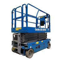
Terex Genie GS-3246 Maintenance Manual (92 pages)
Brand: Terex
|
Category: Scissor Lifts
|
Size: 1.83 MB
Table of Contents
-
Models Included in this Manual
3
-
Performance Specifications
13
-
Function Speeds GS-30, GS-32, GS-46, GS-47, GS-55
13
-
Function Speeds GS-69, GS-84, GS-90
13
-
Battery Specifications
17
-
Battery Specifications — DC and be Models
17
-
Engine Operator and Maintenance Manuals
18
-
Hydraulic Specifications
22
-
Hydraulic Relief Valves
22
-
Hydraulic and Drive Hub Fluid Capacities
24
-
Hydraulic Oil Specifications
25
-
Hydraulic Hose and Fitting Torque Specifications
28
-
Maintenance Procedures
31
-
Pre-Delivery Preparation Report
34
-
Scheduled Maintenance Inspection Report — Scissor Lifts
35
-
Programmed Maintenance Inspection Report — Scissor Lifts
36
-
Commissioning Procedures
37
-
Perform 50 Hour Service
37
-
Perform Engine Maintenance — 50 Hours
37
-
Perform 150 Hour Service
38
-
Quarterly Maintenance Procedures
39
-
Check for Open Bulletins and Owner Registration
39
-
Check the Module Tray Latch Components
43
-
Inspect the Battery Balancer — GS-69 DC
44
-
Inspect the Electrical Wiring
45
-
Inspect the Electrical Contactor
46
-
Inspect the Voltage Inverter (if Equipped)
46
-
Test the Flashing Beacons (if Equipped)
48
-
Visual Inspection of the Hydraulic Oil
48
-
Inspect the Hydraulic Filters
49
-
Check the Exhaust System — Engine Models
50
-
Inspect the Fuel Tank Check Valve Venting System — GS-69 RT Gas Models
51
-
Test the Fuel Select Operation — Gasoline/Lpg Models
51
-
Check and Adjust the Engine RPM
52
-
Inspect the Tires, Wheels and Lug Nut Torque
55
-
Confirm the Proper Brake Configuration — GS-69, GS-84, GS-90
55
-
Test the Drive Speed — Stowed Position
56
-
Test the Drive Speed — Raised Position
57
-
Test the down Limit Switch, Level Sensor and Pothole Limit Switches
57
-
Test the Platform Gate Proximity Switches and the Extension Deck Limit Switch — GS-2646 AV, GS-2646 AV35
61
-
Annual Maintenance Procedures
64
-
Check the Drive Hub Oil Level and Fastener Torque
64
-
Test the Function Pump — GS-69 be and GS-69 DC
65
-
Test the Oscillate Axle — GS-90
65
-
Test the down Limit Switch Descent Delay
68
-
And GS-90 (if Equipped)
68
-
Test the Platform Overload Pressure Transducer and Platform Height Sensor — GS-30, GS-32, GS-46, GS-47 (if Equipped)
70
-
Check the Steer Yoke King Pin Fastener Torque
72
-
Programmed Maintenance Procedures
73
-
P0-1 Inspect the Engine Air Filter — GS-69 RT
73
-
P0-2 Grease the Steer Yokes — GS-30, GS-32, GS-46, GS-47
74
-
P0-3 Deutz Engine Maintenance — under 1000 Hours
75
-
P0-4 Ford Engine Maintenance — under 1000 Hours
76
-
P0-5 Kohler Engine Maintenance — under 1000 Hours
77
-
P0-6 Kubota Engine Maintenance — under 1000 Hours
78
-
P0-7 Perkins Engine Maintenance — under 1000 Hours
79
-
P0-8 GM Engine Maintenance — under 1000 Hours
80
-
P1-1 Perform Engine Maintenance — 1000 Hours
81
-
P1-2 Replace the Drive Hub Oil — GS-69, GS-84, GS-90
82
-
P2-1 Perform Engine Maintenance — 2000 Hours
82
-
P2-2 Replace the Hydraulic Filters
83
-
P2-3 Check the Free-Wheel Configuration — GS-84 and GS-90
84
-
P2-4 Check the Scissor Arm Wear Pads (and Slider Blocks, if Equipped)
86
-
P2-5 Grease the Steer Axle Wheel Bearings — GS-69 be and GS-69 DC
89
-
P2-6 Test or Replace the Hydraulic Oil
90
-
P3-1 Perform Engine Maintenance — 3000 Hours
91

Terex Genie GS-3246 Operator’s Manual (107 pages)
Brand: Terex
|
Category: Scissor Lifts
|
Size: 17.97 MB
Table of Contents
-
Symbol and Hazard Pictorials Definitions
8
-
Operating Instructions
72
-
Transport and Lifting Instructions
89

Terex Genie GS-3246 Operator’s Manual (92 pages)
Brand: Terex
|
Category: Boom Lifts
|
Size: 12.28 MB
Table of Contents
-
Symbol and Hazard Pictorials Definitions
8
-
Operating Instructions
56
-
Transport and Lifting Instructions
73

Terex Genie GS-3246 Operator’s Manual (62 pages)
Brand: Terex
|
Category: Scissor Lifts
|
Size: 4.54 MB
Table of Contents
-
Symbol and Hazard Pictorials Definitions
5
-
Operating Instructions
40
-
Transport and Lifting Instructions
48
Terex Genie GS-3246 Installation Instructions Manual (15 pages)
SmartLink Software Update
Brand: Terex
|
Category: Scissor Lifts
|
Size: 2.11 MB
Table of Contents
-
Before Starting Installation
8
Advertisement
Related Products
-
Terex Genie GS-3246 XH
-
Terex Genie GS-3268DC
-
Terex GS3211A-110000
-
Terex GS3212C-10000
-
Terex GS3216C-17299
-
Terex GS3216P-148699
-
Terex GS32C-17300
-
Terex GS32D-10100
-
Terex GS32P-200100
-
Terex Genie GS-1530
Terex Categories
Boom Lifts
Lifting Systems
Construction Equipment
Scissor Lifts
Compact Loader
More Terex Manuals
Genie
GS_3246 Брошюра
Популярность:
2267 просмотры
Подсчет страниц:
12 страницы
Тип файла:
Размер файла:
1.64 Mb
| Рабочая высота, м: | 11.75 |
| Грузоподъемность, кг: | 318 |
| Тип питания: | Электрический |
| Длина, м: | 2.41 |
| Ширина, м: | 1.17 |
| Высота в сложенном положении, м: | 2.39 |
| Вес, кг: | 2812 |
| Производитель: | GENIE |
| Цена, ₽: | по запросу |
Характеристики

Рабочая высота, м:
11.75

Вес, кг:
2812

Грузоподъемность, кг:
318

Тип питания:
Электрический

Высота в сложенном положении, м:
2.39

Длина, м:
2.41

Ширина, м:
1.17

Скорость движения, км/ч:
3.5

Максимально допустимый уклон, °:
25

Шасси:
Шины

Производство:
США

Производитель:
GENIE
Фотографии
1/7
Сервис
Круглосуточная сервисная поддержка и выезд специалиста по всей России
Подробнее о сервисе
Рассчитать стоимость ежегодного ТО

Service ManualPart No. 72972September 2006Rev B2
IntroductionJune 2003ImportantSerial Number InformationRead, understand and obey the safety rules andoperating instructions in the Genie GS-2032 andGS-2632 and GS-2046 and GS-2646 and GS-3246Operator’s Manual before attempting anymaintenance or repair procedure.Genie Industries offers the following ServiceManuals for these models:This manual provides detailed scheduledmaintenance information for the machine ownerand user. It also provides troubleshooting andrepair procedures for qualified serviceprofessionals.TitlePart No.Genie GS-2046 and GS-2646 and GS-3246Service Manual (before serial number 17408) . 48339Basic mechanical, hydraulic and electricalskills are required to perform most procedures.However, several procedures require specializedskills, tools, lifting equipment and a suitableworkshop. In these instances, we stronglyrecommend that maintenance and repair beperformed at an authorized Genie dealerservice center.Technical PublicationsGenie Industries has endeavored to deliver thehighest degree of accuracy possible. However,continuous improvement of our products is a Geniepolicy. Therefore, product specificationsare subject to change without notice.Readers are encouraged to notify Genie of errorsand send in suggestions for improvement. Allcommunications will be carefully considered forfuture printings of this and all other manuals.Copyright 1997 by Genie IndustriesContact Us:PO Box 97030Redmond, WA 98073-9730 USAwww.genieindustries.come-mail: techsup@genieind.com72972 Rev B June 2003Second Edition, Second Printing»Genie» is a registered trademark of GenieIndustries in the USA and many other countries.»GS» is a trademark of Genie Industries.Printed on recycled paperPrinted in U.S.A.iiGenie GS-2046 and GS-2646 and GS-3246Part No. 72972
June 2003Section 1 Safety RulesSafety RulesDangerFailure to obey the instructions and safety rulesin this manual and the Genie GS-2032 andGS-2632 and GS-2046 and GS-2646 and GS-3246Operator’s Manual will result in death or seriousinjury.Many of the hazards identified in theoperator’s manual are also safety hazardswhen maintenance and repair proceduresare performed.Do Not Perform MaintenanceUnless:You are trained and qualified to performmaintenance on this machine.You read, understand and obey:- manufacturer’s instructions and safety rules- employer’s safety rules and worksiteregulations- applicable governmental regulationsYou have the appropriate tools, liftingequipment and a suitable workshop.Part No. 72972Genie GS-2046 and GS-2646 and GS-3246iii
Section 1 Safety RulesJune 2003SAFETY RULESPersonal SafetyAny person working on or around a machine mustbe aware of all known safety hazards. Personalsafety and the continued safe operation of themachine should be your top priority.Read each procedure thoroughly. Thismanual and the decals on the machine,use signal words to identify the following:Safety alert symbol—used to alertpersonnel to potential personalinjury hazards. Obey all safetymessages that follow this symbolto avoid possible injury or death.Red—used to indicate thepresence of an imminentlyhazardous situation which, if notavoided, will result in death orserious injury.Orange—used to indicate thepresence of a potentiallyhazardous situation which, if notavoided, could result in death orserious injury.Yellow with safety alert symbol—used to indicate the presence of apotentially hazardous situationwhich, if not avoided, may causeminor or moderate injury.Yellow without safety alertsymbol—used to indicate thepresence of a potentiallyhazardous situation which, if notavoided, may result in propertydamage.Be sure to wear protective eye wear andother protective clothing if the situationwarrants it.Be aware of potential crushing hazardssuch as moving parts, free swinging orunsecured components when lifting orplacing loads. Always wear approved steel-toedshoes.Workplace SafetyBe sure to keep sparks, flames andlighted tobacco away from flammable andcombustible materials like battery gasesand engine fuels. Always have an approved fireextinguisher within easy reach.Be sure that all tools and working areasare properly maintained and ready foruse. Keep work surfaces clean and free ofdebris that could get into machine components andcause damage.Be sure any forklift, overhead crane orother lifting or supporting device is fullycapable of supporting and stabilizing theweight to be lifted. Use only chains or straps thatare in good condition and of ample capacity.Be sure that fasteners intended for onetime use (i.e., cotter pins and self-lockingnuts) are not reused. These componentsmay fail if they are used a second time.Be sure to properly dispose of old oil orother fluids. Use an approved container.Please be environmentally safe .Be sure that your workshop or work areais properly ventilated and well lit.Green—used to indicate operationor maintenance information.ivGenie GS-2046 and GS-2646 and GS-3246Part No. 72972
June 2003Table of ContentsIntroductionImportant Information . iiSection OneSafety RulesGeneral Safety Rules . iiiSection TwoSpecifications — Rev BMachine Specifications . 2 — 1Performance Specifications . 2 — 2Hydraulic Specifications . 2 — 3Manifold Component Specifications . 2 — 4Hydraulic Hose and Fitting Torque Specifications . 2 — 6Section ThreeScheduled Maintenance ProceduresIntroduction . 3 — 1Pre-delivery Preparation Report . 3 — 3Maintenance Inspection Report . 3 — 5Checklist A Procedures — Rev BPart No. 72972A-1Perform Pre-operation Inspection . 3 — 6A-2Perform Function Tests . 3 — 6A-3Perform 30 Day Service . 3 — 7A-4Grease the Steer Yokes . 3 — 7Genie GS-2046 and GS-2646 and GS-3246v
September 2006TABLE OF CONTENTSSection ThreeMaintenance Procedures, continuedChecklist B Procedures — Rev CB-1Inspect the Batteries . 3 — 8B-2Inspect the Electrical Wiring . 3 — 9B-3Inspect the Tires and Wheels (including castle nut torque) . 3 — 10B-4Test the Key Switch . 3 — 10B-5Test the Automotive-style Horn (if equipped) . 3 — 11B-6Test the Drive Brakes . 3 — 12B-7Test the Drive Speed — Stowed Position . 3 — 14B-8Test the Drive Speed — Raised Position . 3 — 15B-9Perform Hydraulic Oil Analysis . 3 — 16B-10 Replace the Hydraulic Tank Return Filter . 3 — 16B-11 Check the Module Tray Latch Components . 3 — 17Checklist C Procedure — Rev CC-1Check the Scissor Arm Wear Pads . 3 — 19Checklist D Procedure — Rev AD-1viTest or Replace the Hydraulic Oil . 3 — 20Genie GS-2046 and GS-2646 and GS-3246Part No. 72972
June 2003TABLE OF CONTENTSSection FourRepair ProceduresIntroduction . 4 — 1Platform Controls — Rev B1-1Circuit Boards . 4 — 21-2Joystick Controller . 4 — 31-3Controller Adjustments . 4 — 51-4Software Configuration . 4 — 13Platform Components — Rev A2-1Platform . 4 — 162-2Platform Extension . 4 — 17Scissor Components — Rev A3-1Scissor Assembly, GS-2046 . 4 — 183-2Scissor Assembly, GS-2646 . 4 — 243-3Scissor Assembly, GS-3246 . 4 — 323-4Lift Cylinder . 4 — 42Ground Controls — Rev BPart No. 729724-1Manual Platform Lowering Cable, GS-2046 and GS-2646 . 4 — 464-2Manual Platform Lowering, GS-3246 . 4 — 474-3Toggle Switches . 4 — 484-4Control Relays . 4 — 494-5Tilt Level Sensor (before serial number 50444) . 4 — 504-6Tilt Level Sensor (after serial number 50443) . 4 — 54Genie GS-2046 and GS-2646 and GS-3246vii
June 2003TABLE OF CONTENTSSection FourRepair Procedures, continuedHydraulic Pump — Rev A5-1Function Pump . 4 — 58Function Manifold — Rev B6-1Function Manifold Components(from serial number 17408 to 17481) . 4 — 606-2Function Manifold Components(from serial number 17482 to 36044) . 4 — 626-3Function Manifold Components(after serial number 36044) . 4 — 646-4Function Manifold Components — Models with Traction Control . 4 — 666-5Valve Adjustments — Function Manifold . 4 — 686-6Platform Lift Relief Valve Manifold Components, GS-3246 Models(before serial number 36045) . 4 — 756-7Valve Adjustments — Lift Relief Manifold, GS-3246 Models(before serial number 36045) . 4 — 766-8Valve Coils . 4 — 78Hydraulic Tank — Rev A7-1Hydraulic Tank . 4 — 80Steer Axle Components — Rev A8-1Yoke and Drive Motor . 4 — 818-2Steer Cylinder . 4 — 838-3Steer Bellcrank . 4 — 84Non-steer Axle Components — Rev A9-1Drive Brake . 4 — 85Brake Release Hand Pump Components — Rev A10-1 Brake Release Hand Pump Components . 4 — 86viiiGenie GS-2046 and GS-2646 and GS-3246Part No. 72972
June 2003TABLE OF CONTENTSSection FiveTroubleshooting Flow Charts and Fault CodesIntroduction . 5 — 1Fault Code Chart (after serial number 17407) — Rev A . 5 — 3ChartNumberChart Title1All Functions Will Not Operate — Rev A . 5 — 42Pump Motor Will Not Operate — Rev A . 5 — 63All Functions Inoperative, Power Unit Starts and Runs — Rev A . 5 — 84Ground Controls Inoperative,Platform Controls Operate Normally — Rev A . 5 — 95Platform Controls Inoperative,Ground Controls Operate Normally — Rev A . 5 — 106Platform Up Function Inoperative — Rev A . 5 — 117Platform Down Function Inoperative — Rev A . 5 — 128Steer Left Function Inoperative — Rev A . 5 — 149Steer Right Function Inoperative — Rev A . 5 — 1610All Drive Functions Inoperative,All Other Functions Operate Normally — Rev A . 5 — 1810ABrake Release Function Inoperative — Rev A . 5 — 1911Drive Forward Function Inoperative — Rev A . 5 — 2012Drive Reverse Function Inoperative — Rev A . 5 — 2113Machine Will Not Drive At Full Speed — Rev A . 5 — 2214Machine Drives At Full Speed With Platform Raised — Rev A . 5 — 2315Limit Switch Function Inoperative — Rev A . 5 — 2416Fault Code 02 — ECM / Platform Communication Error — Rev A . 5 — 2617Fault Code 59 — Parallel/Series Coil Fault — Rev B . 5 — 29Part No. 72972Genie GS-2046 and GS-2646 and GS-3246ix
June 2003TABLE OF CONTENTSSection SixSchematicsIntroduction . 6 — 1Control Relay Layout — Rev A . 6 — 2ECM Pin-out Legend — Rev B . 6 — 4Platform Controls Wiring Diagram(from serial number 17408 to 48054) — Rev B . 6 — 6Platform Controls Wiring Diagram(after serial number 48054) — Rev A . 6 — 7Ground Controls Wiring Diagram, GS-2046 and GS-2646 — Rev B . 6 — 8Ground Controls Wiring Diagram, GS-3246 — Rev B . 6 — 9Level Sensor Box Wiring Diagram — Rev A . 6 — 10Electrical Symbols Legend — Rev B . 6 — 12Electrical Schematic(from serial number 17408 to 21064) — Rev B . 6 — 13Electrical Schematic(from serial number 21065 to 21262) — Rev B . 6 — 15Electrical Schematic(from serial number 21263 to 24438) — Rev B . 6 — 17Electrical Schematic(from serial number 24439 to 25141) — Rev B . 6 — 19Electrical Schematic(from serial number 25142 to 27181) — Rev B . 6 — 21Electrical Schematic(from serial number 27182 to 28936) — Rev B . 6 — 23Electrical Schematic(from serial number 28937 to 33721) — Rev B . 6 — 25Electrical Schematic(from serial number 33722 to 40925) — Rev B . 6 — 27xGenie GS-2046 and GS-2646 and GS-3246Part No. 72972
June 2003TABLE OF CONTENTSSection SixSchematics, continuedElectrical Schematic(from serial number 40926 to 48054) — Rev B . 6 — 29Electrical Schematic(from serial number 48055 to 48717) — Rev A . 6 — 31Electrical Schematic(from serial number 48718 to 49199) — Rev A . 6 — 33Electrical Schematic(after serial number 49199) — Rev A . 6 — 35Hydraulic Symbols Legend and Component Reference — Rev B . 6 — 37Hydraulic Schematic, GS-2046 and GS-2646(from serial number 17408 to 36044) — Rev A . 6 — 38Hydraulic Schematic, GS-2046 and GS-2646(after serial number 36044) — Rev A . 6 — 39Hydraulic Schematic, GS-2046 and GS-2646Models with Traction Control — Rev A . 6 — 40Hydraulic Schematic, GS-3246(from serial number 17408 to 22446) — Rev A . 6 — 41Hydraulic Schematic, GS-3246(from serial number 22447 to 27181) — Rev A . 6 — 42Hydraulic Schematic, GS-3246(from serial number 27182 to 36044) — Rev A . 6 — 43Hydraulic Schematic, GS-3246(after serial number 36044) — Rev A . 6 — 44Hydraulic Schematic, GS-3246Models with Traction Control — Rev A . 6 — 45Part No. 72972Genie GS-2046 and GS-2646 and GS-3246xi
1 Service ManualPart No. 72972 September 2006 Rev B2 Genie GS-2046 and GS-2646 and GS- 3246 Part No. 72972 June 2003iiIntroductionImportantRead, understand and obey the safety rules andoperating instructions in the Genie GS-2032 andGS-2632 and GS-2046 and GS-2646 and GS- 3246 Operator’s Manual before attempting anymaintenance or repair Manual provides detailed scheduledmaintenance information for the machine ownerand user. It also provides troubleshooting andrepair procedures for qualified mechanical, hydraulic and electricalskills are required to perform most , several procedures require specializedskills, tools, lifting equipment and a suitableworkshop. In these instances, we stronglyrecommend that maintenance and repair beperformed at an authorized Genie dealerservice PublicationsGenie Industries has endeavored to deliver thehighest degree of accuracy possible.
2 However,continuous improvement of our products is a Geniepolicy. Therefore, product specificationsare subject to change without are encouraged to notify Genie of errorsand send in suggestions for improvement. Allcommunications will be carefully considered forfuture printings of this and all other Us:PO Box 97030 Redmond, WA 98073-9730 : 1997 by Genie Industries72972 Rev BJune 2003 Second Edition, Second Printing» Genie » is a registered trademark of GenieIndustries in the USA and many other countries.»GS» is a trademark of Genie Industries. Printed on recycled paperPrinted in Number InformationGenie Industries offers the following ServiceManuals for these models:TitlePart GS-2046 and GS-2646 and GS- 3246 Service Manual (before serial number 17408).
3 48339 Part No. 72972 Genie GS-2046 and GS-2646 and GS- 3246 June 2003iiiSafety RulesSection 1 Safety RulesDangerFailure to obey the instructions and safety rulesin this Manual and the Genie GS-2032 andGS-2632 and GS-2046 and GS-2646 and GS- 3246 Operator’s Manual will result in death or of the hazards identified in theoperator s Manual are also safety hazardswhen maintenance and repair proceduresare Not Perform MaintenanceUnless:You are trained and qualified to performmaintenance on this read, understand and obey:- manufacturer s instructions and safety rules- employer s safety rules and worksiteregulations- applicable governmental regulationsYou have the appropriate tools, liftingequipment and a suitable GS-2046 and GS-2646 and GS- 3246 Part No.
4 72972 June 2003 SAFETY RULESP ersonal SafetyAny person working on or around a machine mustbe aware of all known safety hazards. Personalsafety and the continued safe operation of themachine should be your top each procedure thoroughly. Thismanual and the decals on the machine,use signal words to identify the following:Safety alert symbol used to alertpersonnel to potential personalinjury hazards. Obey all safetymessages that follow this symbolto avoid possible injury or used to indicate thepresence of an imminentlyhazardous situation which, if notavoided, will result in death orserious used to indicate thepresence of a potentiallyhazardous situation which, if notavoided, could result in death orserious with safety alert symbol used to indicate the presence of apotentially hazardous situationwhich, if not avoided, may causeminor or moderate without safety alertsymbol used to indicate thepresence of a potentiallyhazardous situation which, if notavoided.
5 May result in used to indicate operationor maintenance sure to wear protective eye wear andother protective clothing if the situationwarrants aware of potential crushing hazardssuch as moving parts, free swinging orunsecured components when lifting orplacing loads. Always wear approved SafetyBe sure to keep sparks, flames andlighted tobacco away from flammable andcombustible materials like battery gasesand engine fuels. Always have an approved fireextinguisher within easy sure that all tools and working areasare properly maintained and ready foruse. Keep work surfaces clean and free ofdebris that could get into machine components andcause sure any forklift, overhead crane orother lifting or supporting device is fullycapable of supporting and stabilizing theweight to be lifted.
6 Use only chains or straps thatare in good condition and of ample sure that fasteners intended for onetime use ( , cotter pins and self-lockingnuts) are not reused. These componentsmay fail if they are used a second sure to properly dispose of old oil orother fluids. Use an approved be environmentally safe .Be sure that your workshop or work areais properly ventilated and well 1 Safety RulesPart No. 72972 Genie GS-2046 and GS-2646 and GS- 3246 June 2003 Table of ContentsvIntroductionImportant OneSafety RulesGeneral Safety Rules ..iiiSection TwoSpecifications — Rev BMachine 2 — 1 Performance 2 — 2 Hydraulic 2 — 3 Manifold Component Specifications ..2 — 4 Hydraulic Hose and Fitting Torque 2 — 6 Section ThreeScheduled maintenance 3 — 1 Pre-delivery Preparation 3 — 3 maintenance Inspection 3 — 5 Checklist A procedures — Rev BA-1 Perform Pre-operation 3 — 6A-2 Perform Function 3 — 6A-3 Perform 30 Day 3 — 7A-4 Grease the Steer Yokes.
7 3 — 7 Genie GS-2046 and GS-2646 and GS- 3246 Part No. 72972 September 2006 TABLE OF CONTENTSviSection ThreeMaintenance procedures , continuedChecklist B procedures — Rev CB-1 Inspect the Batteries .. 3 — 8B-2 Inspect the Electrical 3 — 9B-3 Inspect the Tires and Wheels (including castle nut torque).. 3 — 10B-4 Test the Key Switch ..3 — 10B-5 Test the Automotive-style Horn (if equipped) .. 3 — 11B-6 Test the Drive 3 — 12B-7 Test the Drive Speed — Stowed 3 — 14B-8 Test the Drive Speed — Raised 3 — 15B-9 Perform Hydraulic Oil 3 — 16B-10 Replace the Hydraulic Tank Return Filter .. 3 — 16B-11 Check the Module Tray Latch Components ..3 — 17 Checklist C Procedure — Rev CC-1 Check the Scissor Arm Wear Pads .. 3 — 19 Checklist D Procedure — Rev AD-1 Test or Replace the Hydraulic Oil.
8 3 — 20 Part No. 72972 Genie GS-2046 and GS-2646 and GS- 3246 June 2003 TABLE OF CONTENTSviiSection FourRepair 4 — 1 Platform Controls — Rev B1-1 Circuit 4 — 21-2 Joystick 4 — 31-3 Controller 4 — 51-4 Software 4 — 13 Platform Components — Rev 4 — 162-2 Platform Extension .. 4 — 17 Scissor Components — Rev A3-1 Scissor Assembly, GS-2046 ..4 — 183-2 Scissor Assembly, GS-2646 ..4 — 243-3 Scissor Assembly, GS- 3246 ..4 — 323-4 Lift 4 — 42 Ground Controls — Rev B4-1 Manual Platform Lowering Cable, GS-2046 and GS-2646 ..4 — 464-2 Manual Platform Lowering, 4 — 474-3 Toggle 4 — 484-4 Control Relays .. 4 — 494-5 Tilt Level Sensor (before serial number 50444) ..4 — 504-6 Tilt Level Sensor (after serial number 50443) ..4 — 54 Genie GS-2046 and GS-2646 and GS- 3246 Part No.
9 72972 June 2003 TABLE OF CONTENTS viiiSection FourRepair procedures , continuedHydraulic Pump — Rev A5-1 Function 4 — 58 Function Manifold — Rev B6-1 Function Manifold Components(from serial number 17408 to 17481) .. 4 — 606-2 Function Manifold Components(from serial number 17482 to 36044) .. 4 — 626-3 Function Manifold Components(after serial number 36044) .. 4 — 646-4 Function Manifold Components — Models with Traction Control ..4 — 666-5 Valve Adjustments — Function Manifold .. 4 — 686-6 Platform Lift Relief Valve Manifold Components, GS- 3246 Models(before serial number 36045).. 4 — 756-7 Valve Adjustments — Lift Relief Manifold, GS- 3246 Models(before serial number 36045).. 4 — 766-8 Valve 4 — 78 Hydraulic Tank — Rev A7-1 Hydraulic 4 — 80 Steer Axle Components — Rev A8-1 Yoke and Drive 4 — 818-2 Steer 4 — 838-3 Steer 4 — 84 Non-steer Axle Components — Rev A9-1 Drive Brake.
10 4 — 85 Brake Release Hand Pump Components — Rev A10-1 Brake Release Hand Pump 4 — 86 Part No. 72972 Genie GS-2046 and GS-2646 and GS- 3246 June 2003 TABLE OF CONTENTSixSection FiveTroubleshooting Flow Charts and Fault 5 — 1 Fault Code Chart (after serial number 17407) — Rev A .. 5 — 3 ChartNumberChart Title1 All Functions Will Not Operate — Rev 5 — 42 Pump Motor Will Not Operate — Rev A .. 5 — 63 All Functions Inoperative, Power Unit Starts and Runs — Rev 5 — 84 Ground Controls Inoperative,Platform Controls Operate Normally — Rev A .. 5 — 95 Platform Controls Inoperative,Ground Controls Operate Normally — Rev A .. 5 — 106 Platform Up Function Inoperative — Rev A .. 5 — 117 Platform Down Function Inoperative — Rev A .. 5 — 128 Steer Left Function Inoperative — Rev A.