Даже при регулярном техническом обслуживании не удается предотвратить неисправности дизель-генератора. Чтобы обеспечить максимально быстрый ввод оборудования в эксплуатацию, рекомендуем ознакомиться с наиболее распространенными поломками, характерными для агрегатов этого класса. Обратите внимание — перечень неисправностей характерен и для промышленных, и для бытовых агрегатов.
ДГУ не запускается — основные причины
Подобные ошибки дизель-генератора характерны для следующих неисправностей:
Разряд аккумуляторных батарей или снижение давления в баллонах сжатого воздуха, обеспечивающих запуск двигателя. Если не завелся ДГУ после простоя (на протяжении нескольких месяцев), то причину искать необходимо именно в этом.
Выход из строя топливного насоса, что приводит к неравномерной или недостаточной подаче горючего в дизельный двигатель.
Применение некачественного или загрязненного горючего, что становится причиной засорения топливного фильтра.
Зачастую в зимних условиях не запускается дизель-генератор по причине применения не соответствующего сезону топлива. Летняя солярка парафинизируется, превращаясь практически в вязкое желе.
В большинстве случаев, если не заводится дизель-генератор, причины следует искать в топливной системе или в пусковых устройствах. Помимо этого, при появлении проблем с запуском агрегата в работу в холодных условиях стоит обратить внимание на работоспособность предпускового подогрева оборудования.
Проблемы с напряжением — причины падения напряжения на дизель-генераторе при нагрузке
Большая часть проблем обычно связана не с тем, что не заводится дизельный генератор, а с тем, что при работе двигателя в штатном режиме оборудование не выдает заявленную мощность или уровень напряжения занижен. Для электрической части оборудования характерны неисправности следующих типов:
Нарушение контакта в местах подсоединения проводов, износ щеток генератора.
Причина просадки с 380 до 330 В у трехфазного агрегата может быть связана с недостаточной подачей напряжения в цепь возбуждения, кроме того, свою роль может сыграть и перекос фаз при неравномерной нагрузке.
Если дизельный генератор выдает повышенное напряжение, проблему стоит искать в работе устройства AVR (регулятор напряжения).
В случаях, когда дизельный генератор не выдает напряжения совсем, следует обратить внимание на автомат защиты или предохранители, которые могут выйти из строя из-за токовой перегрузки или короткого замыкания в цепи.
При ситуациях, когда ДГУ работает с недовозбуждением, ток отстает от напряжения по фазе на 90 градусов, то есть становится индуктивным по отношению в сети. Длительная эксплуатация установки в таком режиме недопустима.
Особую опасность представляет встречное напряжение при работе ДГУ. Причина такой неисправности связана с повреждением переключателя или АВР, при котором питание подается из основной сети и самого генератора.
Для подключаемой нагрузки особо опасным считается повышенное напряжение на выходе ДГУ. Причины перенапряжения в дизель-генераторе могут отличаться, но в любом случае это способно вызвать выход обслуживаемого оборудования и устройств из строя.
При эксплуатации установок этого класса следует придерживаться простого правила — запуск дизельного двигателя при неисправном генераторе запрещен. Это может стать причиной выхода из строя обмоток статора и ротора, ремонт в таком случае обойдется дорого, в отдельных случаях дешевле будет купить новый ДГУ.
Самопроизвольное отключение — почему глохнет дизель-генератор
Нестабильно работающая установка или регулярное самопроизвольное отключение может быть вызвана рядом факторов. Но если разбираться, почему сам отключается дизельный генератор, оказывается, что причины связаны с топливной системой:
Недостаточный уровень горючего в топливном баке.
В систему попал воздух.
Используется топливо, не соответствующее сезону.
Забитый воздушный фильтр.
Повышенное сопротивление в выпускной и впускной системе.
Вышла из строя система подогрева топливного фильтра.
Кроме того, двигатель ДГУ глохнет и при неправильной регулировке количества оборотов на холостом ходу.
Стук двигателя
Если при работе дизельного двигателя появились посторонние шумы или стуки, установку следует немедленно остановить. Причина таких звуковых эффектов может быть связана со следующими повреждениями:
Повреждение или износ кривошипно-шатунного механизма, его подшипников.
Наличие посторонних предметов в камере сгорания.
Неправильно отрегулирован момент подачи топлива.
Повреждения клапанов или распределительного вала.
Вышли из строя поршневые кольца.
Если глобальные проблемы не обнаружены, следует проверить регулировку клапанов, механизма газораспределения. Кроме того, причина появления стуков при работе ДВС часто связана с применением несоответствующего топлива, в том числе и с высокооктановыми добавками. Посторонние шумы могут появиться и при постоянной эксплуатации перегретого двигателя, в этом случае стоит обратить внимание на состояние системы охлаждения.
Причины увеличенного расхода масла
При эксплуатации ДГУ обращайте внимание и на увеличившийся расход масла, это может свидетельствовать о серьезных проблемах, среди которых выделим:
Вышли из строя поршневые кольца или повреждено зеркало самих цилиндров.
Закоксованы прорези на маслосъемных кольцах или соответствующие канавки на поршнях, что произошло вследствие использования несоответствующего масла.
Выход из строя или чрезмерный износ маслоотражательных колпачков, установленных на клапанах.
Повреждения клапанов и других деталей газораспределительного механизма.
При эксплуатации обращают внимание и на цвет выхлопных газов, если двигатель стал дымить, это связано со следующими проблемами:
Закоксованы форсунки, которые обеспечивают впрыск горючего
Залегли поршневые кольца.
Загрязнен воздушный фильтр.
Отметим, что повышенный расход масла практически всегда вызывает обильное дымообразование и изменение цвета выхлопных газов. Именно по этим признакам можно определить чрезмерное потребление смазочных материалов даже без проверки уровня в картере.

Похожие материалы

Как выбирать дизельную электростанцию: главные критерии и нюансы выбора

Правила эксплуатации дизель-генераторов

Объективные преимущества и недостатки дизельных генераторов

Принцип работы дизель-генератора

Срок службы дизель-генератора: чем определяется и как сэкономить моторесурс?
Коды ошибок для принтера phaser 6000
Когда на принтере возникает ошибка, начинает светиться или мигать светоиндикатор
ошибки. Когда включается светоиндикатор ошибки, начинает светиться одна или несколько
пиктограмм, указывая неисправность. Мигание индикатора ошибки означает, что из-за
ошибки принтер не работает. Для устранения ошибки требуется перезагрузка или ремонт
принтера. Если светоиндикатор ошибки горит постоянным светом, либо светятся или
мигают пиктограммы, значит требуется вмешательство пользователя. В следующей
таблице содержатся пиктограммы для ошибок или указание необходимых действий.
Если пиктограмма крупная, значит она светится постоянным светом.
Если пиктограмма мелкая и с лучами, значит она мигает.
Ошибки и меры по устранению
Низкий уровень тонера (C, M, Y или K). Закажите тонер указанного
цвета. Принтер может печатать.
Предупреждение по тонеру. Замените тонер-картридж, если это
необходимо. Тонер закончился или картридж неисправен.
Нет тонера или ошибка микросхемы CRUM картриджа.
Переустановите тонер-картридж. Убедитесь, что тонер
соответствует принтеру.
Закройте заднюю крышку. Если задняя крышка закрыта, см. раздел
Принтер в ожидании печати второй стороны при выполнении работы
двусторонней печати в ручном режиме. Не меняя ориентацию листов,
переложите бумагу из выходного лотка во входной и нажмите
кнопку OK.
Лоток для бумаги пуст. Загрузите бумагу.
Несоответствие размера бумаги. В лотке бумага неподходящего
размера. Загрузите бумаги соответствующего размера.
Застревание бумаги. Извлеките застрявшую бумагу из лотка.
Застревание бумаги. Откройте заднюю крышку и извлеките
застрявшую бумагу. Проверьте, не осталось ли в лотке
обрывков бумаги.

Устранение неисправностей Цветной принтер Phaser.
Цветной принтер Phaser 6000/6010
Руководство пользователя
Дополнительные коды ошибок для принтера Phaser 6000
Когда на принтере возникает ошибка, включается светоиндикатор ошибки. Когда
включается светоиндикатор ошибки, начинает светиться или мигать другой индикатор,
указывая характер неисправности. Если при включении светоиндикатора ошибки никакой
другой индикатор не включился, закройте заднюю крышку. Если задняя крышка закрыта,
нажмите кнопку OK и удерживайте более 3 секунд. Проверьте, не включилась ли группа
дополнительных светоиндикаторов. Группа дополнительных светоиндикаторов включается
примерно на 3 секунды, затем горит только светоиндикатор ошибки. Нажимайте кнопку OK,
пока не проверите включение всей группы светоиндикаторов. Пользуясь следующей
таблицей, можно определить код ошибки по группе светоиндикаторов.
Выполните чистку датчика плотности цветного тонера.
Переполнение памяти. Разделите работу печати на несколько файлов.
Ошибка PDL. Убедитесь, что используется драйвер принтера
Проблемы с принтером
Цветной принтер Phaser 6000/6010
Проблемы с принтером
Если в принтере возникли проблемы, используйте следующую таблицу для выявления
причины и устранения неисправности. Для получения дополнительной информации по
устранению неисправностей см. раздел
ПРЕДУПРЕЖДЕНИЕ:
Не открывайте и не снимайте крышки принтера,
закрепленные винтами, если это не указано в руководстве. Компоненты
под высоким напряжением могут стать причиной поражения
электрическим током. Не следует изменять конфигурацию принтера,
нельзя модифицировать его узлы. Несанкционированное изменение
конструкции принтера может привести к появлению дыма и возгорания.
Возможными причинами неисправности является то, что
принтер, компьютер, сервер или другое используемое оборудование
неправильно настроено для работы в сети.
Причина/Решение
Подается ли на принтер питание?
Переведите кнопку питания в положение Вкл. для включения
питания принтера.
Возможно, что шнур питания отсоединен или подключен ненадежно.
Выключите принтер и надежно подключите шнур питания к
розетке. Затем снова включите принтер.
Шнур питания подключен к розетке с правильным напряжением?
Принтер должен быть подключен к сетевой розетке,
обеспечивающей соответствующее напряжение и ток.
Подробности см.
Возможно, что принтер подключен к источнику
бесперебойного питания.
Выключите принтер и подключите шнур питания к
подходящей розетке.
Возможно, что принтер подключен к разветвителю питания
вместе-с другими электроприборами большой мощности.
Подключите принтер к разветвителю питания, к которому не
подключены другие электроприборы большой мощности.
Для перезагрузки принтера выключите и снова включите его.
Только для принтера
6010. Отображается ли сообщение
на панели управления?
Для устранения проблемы прочтите сообщение и
выполните указания.
Устранение неисправностей Цветной принтер Phaser.
Цветной принтер Phaser 6000/6010
Руководство пользователя
Работа печати отправлено,
но индикатор Готов не
мигает и не светится.
Только для принтера
6010. Возможно, что отсоединен
интерфейсный кабель Ethernet или USB.
Выключите питание и проверьте подключение
интерфейсного кабеля.
Только для принтера
6010. Настроен ли протокол?
Проверьте состояние порта интерфейса связи. Убедитесь, что
настройки протокола правильно установлены в Интернет-службах
CentreWare IS. Подробные сведения см. справку по
Интернет-службам CentreWare IS.
Правильно ли настроено рабочее окружение принтера?
Проверьте рабочую среду компьютера, например,
драйвер принтера.
Светится индикатор
Ошибка.
6000: Проверьте код ошибки, см. раздел
6010: Отображается ли сообщение об ошибке на
панели управления?
Проверьте отображаемое сообщение и устраните ошибку.
Мигает индикатор Ошибка.
Возникла ошибка, которую вы не сможете
устранить самостоятельно.
Запишите отображаемое сообщение об ошибке или код ошибки,
выключите питание и выньте вилку шнура питания из розетки.
Посетите сайт технической поддержки Xerox
Индикатор Готов светится
и мигает, но отпечатки
не выводятся.
В принтере остались работы печати.
Отмените печать или принудительно распечатайте
оставшиеся данные.
Чтобы принудительно распечатать работу печати, нажмите кнопку
ОК. Для отмены работы нажмите кнопку Отменить.
На отпечатке документа
отсутствует верхняя часть.
Неправильно настроены
верхнее и боковые поля.
Правильно ли установлены направляющие бумаги (ограничители)?
Правильно установите направляющие по длине и ширине листа
бумаги. Подробные сведения см. Краткое руководство по
эксплуатации, раздел по основным операциям печати.
Проверьте, что в драйвере принтера и на панели управления
правильно настроен формат бумаги. Подробные сведения см.
справку в Интернете для драйвера принтера.
Конденсация внутри
принтера.
Включите принтер и оставьте его включенным хотя бы на один час,
чтобы избавиться от конденсата. Если проблема не устраняется,
посетите сайт технической поддержки Xerox
Причина/Решение
Устранение неисправностей Цветной принтер Phaser.
Цветной принтер Phaser 6000/6010
Бумага не подается.
Застревание бумаги.
Подается несколько
листов сразу.
Лист бумаги подается
с перекосом.
Бумага сминается.
Правильно ли загружена бумага?
Правильно загрузите бумагу. При загрузке наклеек и конвертов
распустите их, чтобы исключить слипание отдельных листов.
Возможно, что бумага отсырела.
Используемая бумага не пригодна для принтера.
Загрузите бумагу допустимого типа. Подробные сведения см.
Краткое руководство по эксплуатации, раздел по основным
операциям печати.
Обходной лоток установлен правильно?
Убедитесь, что обходной лоток правильно установлен на лотке
для бумаги.
Принтер стоит на плоской поверхности?
Установите принтер на устойчивую, плоскую поверхность.
Правильно ли установлены направляющие бумаги в лотках?
Установите направляющие в правильное положение. Подробности
сведения см. Краткое руководство по эксплуатации, раздел по
загрузке бумаги.
Одновременно подается более 1 листа бумаги.
Подача нескольких листов бумаги может возникнуть перед
окончанием бумаги в лотке. Выньте бумагу из лотка, распушите ее
и снова загрузите в лоток. Загружайте в лоток бумагу только после
окончания загруженных в него листов.
Принтер установлен не горизонтально.
Поместите принтер на плоскую устойчивую поверхность.
Внутри принтера имеется посторонний предмет.
Выключите принтер и извлеките посторонний предмет. Посетите
сайт технической поддержки Xerox
Источники:
https://abespb. ru/press/articles/neispravnosti-dizel-generatora-i-ikh-ustranenie/
https://manualza. ru/xerox/phaser-6000/bbjd41


Location Offline
Junior Member
Reputation:
0
Thanks Given: 178
Thanks Received: 5 (4 Posts)
Posts:
45
Threads:
15
Joined: Apr 2011
1
03-13-2013, 03:20 AM
please help i need genpart 6000 control panel manual
Reputation:
6
Thanks Given: 28
Thanks Received: 82 (9 Posts)
Posts:
9
Threads:
7
Joined: Apr 2011
2

03-13-2013, 08:02 AM
FGW 6000 Series is same as WoodWard EGCP-1, It just re named by FGW — See attached… please give thanks if usefull. Factory access code for calibration menu is 7529.
Attached Files

Woodward EGCP-1 Engine Generator Control Package 26059.rar
Reputation:
0
Thanks Given: 178
Thanks Received: 5 (4 Posts)
Posts:
45
Threads:
15
Joined: Apr 2011
3
03-13-2013, 01:37 PM
(03-13-2013, 08:02 AM)starandmoon Wrote: FGW 6000 Series is same as WoodWard EGCP-1, It just re named by FGW — See attached… please give thanks if usefull. Factory access code for calibration menu is 7529.
thank you my friend you solve my problem
Thanks given by:
Reputation:
0
Thanks Given: 178
Thanks Received: 5 (4 Posts)
Posts:
45
Threads:
15
Joined: Apr 2011
4
04-21-2013, 01:33 AM
YOU shore my friend that the code is 7529 i enter the code and nothing happen please help me
Thanks given by:
Reputation:
6
Thanks Given: 28
Thanks Received: 82 (9 Posts)
Posts:
9
Threads:
7
Joined: Apr 2011
5
04-26-2013, 06:09 AM
(04-21-2013, 01:33 AM)ahmedkotb_2007 Wrote: YOU shore my friend that the code is 7529 i enter the code and nothing happen please help me
You put code in and press bottom left hand «ENTER» arrow. Code disappear. Then you press lower «tear drop» key on the right hand side. Configuration menu should come up for edit. 
![]()
Reputation:
1
Thanks Given: 13
Thanks Received: 4 (3 Posts)
Posts:
55
Threads:
24
Joined: Apr 2013
6
11-21-2021, 11:52 PM
(03-13-2013, 08:02 AM)starandmoon Wrote: FGW 6000 Series is same as WoodWard EGCP-1, It just re named by FGW — See attached… please give thanks if usefull. Factory access code for calibration menu is 7529.
Very useful and I want to give a thanks but don’t see where I can do that from. Please let me know how I can give a thanks.
Thanks given by:
INTELLIGENT WORK FORUMS
FOR ENGINEERING PROFESSIONALS
Contact US
Thanks. We have received your request and will respond promptly.
Log In
Come Join Us!
Are you an
Engineering professional?
Join Eng-Tips Forums!
- Talk With Other Members
- Be Notified Of Responses
To Your Posts - Keyword Search
- One-Click Access To Your
Favorite Forums - Automated Signatures
On Your Posts - Best Of All, It’s Free!
*Eng-Tips’s functionality depends on members receiving e-mail. By joining you are opting in to receive e-mail.
Posting Guidelines
Promoting, selling, recruiting, coursework and thesis posting is forbidden.
Students Click Here
FG wilson Generator gen part 6000 control panelFG wilson Generator gen part 6000 control panel(OP) 23 Nov 16 13:58 Hello my name is alastair and I am new to the forum so, Hello! I am currently out on a job at a Standby power generator that hasnt been started in 6 years! So, to cut it short. I arrive on site to which the site contact explains the generator was disconected from the ac mains 6 years ago alongs with the batteries to start it. I connect the two batteries in series to give 24v to the starter motor and dc system. So my questions are: The gen part 6000 might be broken ect but Would that stop the engine from starting? as it is started by a rotary switch independant of the module. thanks please help me. A Waters Red Flag SubmittedThank you for helping keep Eng-Tips Forums free from inappropriate posts. |
Resources
Learn methods and guidelines for using stereolithography (SLA) 3D printed molds in the injection molding process to lower costs and lead time. Discover how this hybrid manufacturing process enables on-demand mold fabrication to quickly produce small batches of thermoplastic parts. Download Now
Examine how the principles of DfAM upend many of the long-standing rules around manufacturability — allowing engineers and designers to place a part’s function at the center of their design considerations. Download Now
Metal 3D printing has rapidly emerged as a key technology in modern design and manufacturing, so it’s critical educational institutions include it in their curricula to avoid leaving students at a disadvantage as they enter the workforce. Download Now
This ebook covers tips for creating and managing workflows, security best practices and protection of intellectual property, Cloud vs. on-premise software solutions, CAD file management, compliance, and more. Download Now |


Join Eng-Tips® Today!
Join your peers on the Internet’s largest technical engineering professional community.
It’s easy to join and it’s free.
Here’s Why Members Love Eng-Tips Forums:
- Talk To Other Members
- Notification Of Responses To Questions
- Favorite Forums One Click Access
- Keyword Search Of All Posts, And More…
 Talk To Other Members
Register now while it’s still free!
Already a member? Close this window and log in.
Join Us Close
Выполняемые работы:
ремонт на уровне компонентов, восстановление.
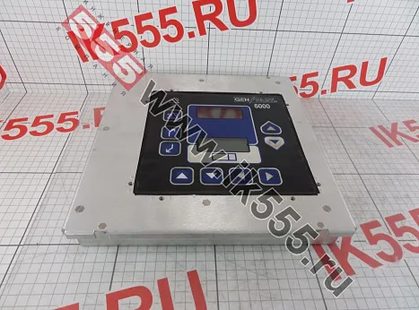
GEN PART 6000 ремонтируется на уровне компонентов с применением новейшего высокоточного и технологичного оборудования. У нас работают квалифицированные инженеры с большим опытом ремонта электроники и возврата в эксплуатацию неисправного оборудования. Это позволяет решать многие проблемы: затраты уменьшаются, и вы не теряете в качестве. Наши специалисты восстановят GEN PART 6000 от производителя WOODWARD, даже если ремонт по определенным причинам считался невозможным. Задайте вопрос по ремонту любого промышленного оборудования WOODWARD в формe обратной связи или позвоните менеджерам по указанному телефону, звонок бесплатный.
- Заявка
- Отзывы
- Описание
- Преимущества
Заявка на ремонт
Постарайтесь подробно описать дефект!
Звоните +7 (800) 555-89-01
Работать с нами просто, схема взаимодействия
1

Консультация по телефону
2

Отправка оборудования на осмотр
3

Оценка стоимости ремонта
4

Оплата счета
5

Ремонт и отправка оборудования
1Консультация по телефону
2Отправка оборудования на осмотр
3Оценка стоимости ремонта
4Оплата счета
5Ремонт и отправка оборудования

Компания ООО «Барс-Гидравлик Групп» на протяжении нескольких лет успешно сотрудничает с ООО «Инженерная компания 555» в вопросах ремонта сложного промышленного оборудования. За время работы наш партнер зарекомендовал себя с самой лучшей стороны. Заказы выполняются в кротчайшие сроки при соблюдении высокого качества работ. Организация приема и выдачи заказов четкая. Гарантийные обязательства выполняются в полном объеме.
Выражаем благодарность Вашим специалистам за профессионализм и оперативное решение поставленных задач.
Особенно хочется отметить высокую клиентоориентированность персонала Вашей компании, готовность помочь в самых сложных ситуациях.
Мы высоко ценим сложившиеся между нашими компаниями открытые и доверительные партнерские отношения и искренне желаем «Инженерной компании «555» долгих лет успеха и процветания.
Читать весь
отзыв

ООО «Инженерная компания «555» оказывала нашей компании услуги по ремонту электродвигателей и проявила пунктуальность, аккуратность и ответственность в работе.
Результат выполненных работ говорит о качественном оборудовании и высококвалифицированных кадрах.
Сотрудники компании готовы выполнить новые для себя виды работ и оказать консультационные услуги, что характеризует их как профессионалов своего дела.
Рекомендуем ООО «ИК «555» как ответственного и надежного поставщика услуг.
Читать весь
отзыв

Сообщаем, что наша организация сотрудничает с ООО «Инженерная компания «555» с мая 2016 года по настоящее время.
За этот период мы обращались к услугам компании более 10 раз.
Благодаря серьезному и квалифицированному подходу сотрудников ООО «Инженерная компания «555» ремонтные работы произведены качественно с учетом сроков, и обеспечены гарантийным сопровождением.
Планируем в дальнейшем работать с ООО «Инженерная компания «555»
Читать весь
отзыв

Уважаемый Дмитрий Васильевич!
ОАО «Октябрьский электровагоноремонтный завод» успешно работает с ООО «Инженерная компания «555» несколько лет, очень довольны данным сотрудничеством. В работе компании наибольшую ценность для нас представляет готовность работать на условиях, удобных Заказчику, качественный ремонт оборудования в заявленные сроки и самое главное, финансовая защищенность Заказчика. В инженерной компании работают внимательные, доброжелательные сотрудники, готовые в любой момент решить проблему Заказчика. Мы рады, что выбрали ООО «Инженерная компания «555» в качестве партнера. Гарантируем дальнейшее сотрудничество!
Читать весь
отзыв

ЗАО «Охтинское» выражает глубокую признательность и истинную благодарность ООО Инженерной компании «555» за качественную работу компании по ремонту сложного оборудования промышленной электроники, оперативность и технически грамотное отношение к работе в течении всего периода сотрудничества.
Мы надеемся на дальнейшее успешное развитие деловых отношений в сфере ремонта промышленной электроники.
Читать весь
отзыв
Преимущества сотрудничества с нами

Оплата только за результат — работающий блок

Гарантия на работоспособность блока целиком 12 месяцев

Срок ремонта от 5 до 15 дней

Бесплатный предварительный осмотр на предмет ремонтопригодности

Не вносим конструктивных изменений

Ремонт на компонентном уровне
Наша лаборатория расположена в Санкт-Петербурге, но обратиться за помощью вы можете из любой точки России.
Закажите обратный звонок или наберите в рабочее время многоканальный телефон
– +7 (800) 555-89-01 (звонок по России бесплатный).
Расскажите о своей проблеме и получите инструкцию к дальнейшим действиям.
Presentation on theme: «FG Wilson Product Training: 6000 Series Control System»— Presentation transcript:
1
FG Wilson Product Training: 6000 Series Control System
Malachy Roscoe
2
Agenda Basics and Terminology of Synchronisation Load Control Methods
6000 Features 6000 Applications The 6000 Series Controller Reprogramming and Calibration Communications Options
3
Q. What do we mean by synchronisation?
In terms of power generation, synchronisation is the matching of the output voltage waveform of one alternating current electrical generator with the voltage waveform of another alternating current electrical system. For two systems to be synchronised, five conditions must be matched:
4
Q. What are the five conditions of synchronisation?
The number of phases in each system The direction of rotation of these phases The voltage amplitudes of the two systems The frequencies of the two systems The phase angle of the the voltage of the two systems
5
Number of Phases G Mains or Generator
The generating set of the oncoming system must have the same number of phases as those of the system it is to be paralleled: L1 L1 L2 L2 Mains or Generator G L3 L3
6
Phase Rotation Each generator or system being paralleled must be connected so that all phases rotate in the same direction.
7
Voltage Match The voltages generated by the systems being paralleled must be within a small percentage of one another, typically 1-5%. .
8
Voltage Match If two systems of unequal voltage are paralleled, the difference in voltages result in reactive currents and lowered efficiency If a generator is paralleled to the mains, a difference in voltage before paralleling will not change the voltage of the bus In the above instance, if the generator voltage is much lower than the bus voltage the generator could be motorised.
9
Frequency Match The voltages generated by the systems being paralleled must be within a small percentage of one another, typically 1-5%. .
10
Phase Angle Match The phase relationship between the voltages of the systems must be very close prior to paralleling. This match usually is within +/- 10 degrees.
11
Synchronisation Q. Why is synchronisation important?
When two or more systems are paralleled to the same distribution system, the power sources must be synchronised properly. Without proper synchronisation of the oncoming system, power surges and mechanical or electrical stresses will result when the breaker is closed.
12
Synchronisation Incorrect synchronisation under the worst conditions can lead to:- Voltage’s being twice the rated voltage One system can place a dead short on the other High currents placing both systems under stress Bent shafts and broken coupling discs Power surges which build on each other until both systems are disabled
13
Synchronisation Q. How is synchronisation accomplished?
Normally, one generating system is used to establish the common bus and then the oncoming generator is then synchronised by changing the speed of the prime mover driver the oncoming generator. This can be done manually or automatically.
14
Peak Load Control Peak Load Control refers to limiting the power purchased from the mains supplier. Electrical rates for large industrial users are usually calculated by the peak demand on the mains during a given time. Sometimes a peak demand lasting as brief as 15 minutes out of a 30 day period will determine the charge levelled for all the power purchased during that 30 day period. Peak Load Control can avoid over priced power bills by either: Load Shedding as power levels reach the max defined level Base loading Peak Shaving
15
Base-loading Power Demand
Base-loading is the operation of a generator at a constant output. When load demand exceeds the generator output capacity, power will be imported from the mains. If the base-loading exceeds the load demands, power may be exported to the mains grid. Power Demand Mains Supplied Load Generator Supplied Time
16
Peak Shaving Power Demand
Peak shaving is used to set a limit on the maximum amount of power taken from the mains. The example below shows a maximum import from the mains as 100kW. Load Power Demand Generator Supplied 100kW Mains Supplied Time
17
Import/Export Power Demand
Import Power and Export Power are terms used to describe power taken by the site load (import) or supplied to the mains grid (export) Load Power Demand Import Power Generator Capacity Site Demand Time
18
Import/Export Power Demand
Import Power and Export Power are terms used to describe power taken by the site load (import) or supplied to the mains grid (export) Power Demand Load Generator Capacity Export Power Site Demand Time
19
Zero Import (Export) Control
A generator — or series of generators — is able to supply all the site power demand. This situation usually relies on generators to start and stop as demand fluctuates — Automatic Sequencing. Load Generator System Capacity Site Demand Generator Supplied Time
20
Automatic Synchronisation
A system that will automatically synchronise two systems it must have the able to: Monitor the voltage and frequencies from both systems to be paralleled Bias the voltage on the alternator and speed of the engine Issue a breaker close command
21
Automatic Synchronisation
Bus Electronic Governor Engine Synchroniser Speed Bias Signal Alternator Close Breaker Signal Voltage Regulator Generator Voltage Breaker Typical Auto-Synch System Load
22
6000 Series Controller Automatic Synchroniser
Automatic Sequencing (up to 8 Generators) Proportional Load Sharing (kW/kVAr) 4 Applications for Parallel/No Parallel and Single/Multiple Engine & Generator Protections Available in 12 Languages
23
Language Options English German Swedish French Danish Italian Finnish
Icelandic Norwegian German French Italian Dutch Portuguese Spanish
24
Engine Monitoring Oil Pressure Over/Under Alarm/Shutdown Settings
Water Temperature Battery Voltage Overspeed Alarm/Shutdown Settings
25
Auto-Start Function Programmable Auto Start on Loss of Mains
All units in Auto mode with Loss of Mains detection enabled start and close onto load bus Multiple Crank Repeat Setpoint Crank Repeat Timer Crank Fail Alarm/Shutdown Crank Cutout (RPM) Preglow
26
Generator Monitoring 3 Phase Over/Under Voltage Over Current
Reverse Power Loss of Excitation Over/Under Frequency Stable Generator Determined by Being within Voltage and Frequency Limits for a given period of time
27
Mains Monitoring Over/Under Voltage Over/Under Frequency Load Surge
Programmable for Alarm/Loss of Mains Detect Loss of Mains Action Timer Stable Mains determined by being within Voltage and Frequency Limits for a Given period of time
28
Synchronising Phase Match Synchronisation 3 Mode Operation
run, check, permissive Voltage Matching Dead Bus Closing Synch Timer Reclose Attempt/Timer
29
Load Control Proportional Load Sharing
Integrating Base Load and Process Control Load Ramping Remote Contact Inputs to change Base Load and Process Setpoints with Raise/Lower ramp rates Unload Trip point Droop Load Control Capability
30
Sequencing Each Unit in the system has an assigned Priority
Master (Highest Priority) automatically sequences units on or off line as determined by system load. Higher priority units are sequenced on in order of their priority; taken off in reverse of priority
31
Sequencing System Load setpoints determine percent system load level at which additional units will be brought on, or taken off line Time setpoints determine period of delay for sequencing units on/off line Separate time delay for overload (100%+) system load levels so additional units can be sequenced on line quickly
32
Reactive Load Control Var or Power Factor Load Control in Mains Parallel operation Power Factor Sharing in Load Sharing, No Parallel operation Externally adjustable VAR/PF reference Manual Voltage Control Capability
33
Mains Transfer Functions
Loss of Mains Action Timer Fast Transfer Timer Sets transfer time to/from Mains Mains Stable Timer Gen Stable Timer Up to 8 generator system can re-synchronise across the mains tie on parallel transfer
35
6000 Series Controller Max No. Units Genset Parallel Mains Parallel
6101 1 NO NO 6201 8 YES NO 6301 1 YES NO 6401 8 YES YES
36
6000 Series Controller: 6100 Single Unit No Parallel-6100 Mode (AMF) G
LOAD
37
6000 Series Controller: 6100 Single Unit No Parallel-6100 Mode (AMF)
No Mains PT or Mains C.B. Aux Contact Volt Free Start Signal Load Transfer Functions and Mains Failure Detection Handled Externally Open Load Transfer (External Changeover) Isochronous Load Control Dead Bus Closing
38
6000 Series Controller Typical 6000 Switch Configuration AUTO TEST OFF
RUN
39
FG Wilson Schematic for 6000 Series Control Mode Switch
40
6000 Series Controller: 6100 Single Unit No Parallel-6100 Mode (AMF)
Auto Unit waits for external start signal (AMF) Test Starts engine — if mains fails will power load Run Same as Test
41
6000 Series Controller: 6100 Single Unit Prime Power G LOAD
42
6000 Series Controller: 6100 Single Unit Prime Power
No Mains PT Required No Mains Aux. Required Dead Bus Closing Isochronous Load Control
43
6000 Series Controller: 6100 Single Unit Prime Power Auto
Starts Engine and Runs On Load Test Same as Auto Run Same as Auto and Test
44
6000 Series Controller: 6200 Multi Unit, No Parallel-6200 Mode (AMF) G
Up to 8 Generators G G G LOAD
45
6000 Series Controller: 6200 Multi Unit, No Parallel-6200 Mode (AMF)
Redundancy of Master Units No Mains PT or C.B. Aux Required Dead Bus Closing Isochronous Load Sharing Load Transfer Functions and LOM Detection handled externally Load Dependant Auto Sequencing
46
6000 Series Controller: 6200 Multi Unit, No Parallel-6200 Mode (AMF)
Auto Awaits Volt Free Start Signal Enables Automatic Sequencing Enables Dead Bus Closing Test Starts Engine; no further action If Volt Free Start Signal received closes to bus Run Starts Unit, and Syncs to local bus or alternatively closes to dead bus
47
FG Wilson Schematic for 6000 Series Control Mode Switch for Master 6200
48
FG Wilson Schematic for 6000 Series Control Mode Switch for Master 6200
GST 1GSR 1GTR
49
6000 Series Controller: 6200 When the changeover system senses that the mains has failed relays GSR (Gen Start Relay) will switch its contacts to give the 6000 an AUTO input and also a RUN input through GTR (Generator Timer Relay). This is so that Auto Sequencing will not be enabled for a timed period, GST. Once the time delay on GST (Gen Start Timer) has expired 1GTR will energise and switch its contacts removing the RUN input to the 6000, this means that Auto Sequencing will be enabled and generators will sequence ON/OFF line as required.
50
6000 Series Controller: 6200 Multiple Unit-6200 Mode (Prime Power) G G
Up to 8 Generators G G LOAD
51
6000 Series Controller: 6200 Multiple Unit-6200 Mode (Prime Power)
No Mains PT No Mains Aux. Dead Bus Closing Load Dependant Auto Sequencing
52
6000 Series Controller: 6200 Multiple Unit-6200 Mode (Prime Power)
Auto Will Start the unit in Auto and it will close its gen breaker to the load Enables Auto Sequencing Enables Dead Bus Closing Test Same as Auto but engine always runs Run Starts Unit and allows unit to close gen breaker to the dead bus, or synchronize to a live bus if other generators are already on line. Unit cannot be sequenced off-line
53
6000 Series Controller: 6300 Single Unit Parallel — 6300 Mode G M M
LOAD
54
6000 Series Controller: 6300 Single Unit Parallel — 6300 Mode
Mains PT sensing Mains C.B. Aux Contact Auto input and software setpoints enable Loss Of Mains Detection Isochronous Load Control on isolated bus Dead Bus Closing Soft Re-Transfer from generator to mains on Return of Mains
55
6000 Series Controller: 6300 Single Unit Parallel — 6300 Mode
Auto Position on Control Switch Enables LOM Detection Test Position on Control Switch Starts Engine; no other action LOM Detection Enabled Run Position on Control Switch Synchronises and Ramps to Base Load
56
6000 Series Controller: 6300 Single Unit Parallel — 6300 Mode
Process Switch When individually selected No Action Process Switch ON and Run on Control Switch Synchronises and Ramps to Process Reference with LOM detection Enabled
57
6000 Series Controller: 6300 Single Unit Parallel — 6300 Mode
Process Switch OFF and Run on Control Switch Synchronises and Ramps to Base Load If “Load Control Mode” is set for Soft Transfer in configuration menu, unit will open mains breaker when base load reference is reached.
58
6000 Series Controller: 6300 Single Unit Parallel — 6300 Mode
Process Switch ON and Run on Control Switch Synchronises and Ramps to Process Reference Will open mains breaker/contactor upon reaching Process Reference if “Load Control Mode” setpoint in configuration menu is set for Soft Transfer.
59
6000 Series Controller: 6400 Multiple Unit, Mains Parallel (6400 Mode)
External PLC ControlLogic G M M M G G LOAD
60
6000 Series Controller: 6400 Multiple Unit, Mains Parallel (6400 Mode)
Redundancy of Masters Mains C.B. Aux to all units (through PLC control) Mains PT input to all units (through PLC control) Loss of Mains Detection (through PLC control) Dead Bus Closing Isochronous Load Sharing when Isolated from Mains Base Load, Process, or Soft Transfer Control while in parallel with mains Load Dependant Auto Sequencing in Load Sharing or Process Control
61
Controller Interface Two 16 character, 4 line back lit LCD displays with adjustable contrast Large Keys with tactile feedback Alarm/Shutdown LED indicator Operator Input Keys (up, down, commit, escape, etc.) maintain common functions throughout all controller displays and modes.
62
Hardware 12 or 24 VDC supply voltage
10 Amp /125 VAC (6 Amp 277 VAC) Relays Isolated Power Supply +/- 3VDC Speed Bias Output +/-1, 3 or 9 VDC Voltage Bias Output
63
Hardware RS-422 PC interface network
Multi Drop, Multi Unit access from PC RS-485 Load Sharing network Intercontrol communications 4 Control inputs determining operating mode Auto, Test, Run and Process
64
Keypad Detail Vertical Keys AlarmReset Commit Escape
Resets Alarms Enters Setpoints Escapes Setpoints Clears Alarm Ind Enters Menus Escapes Menus Commits Faults
65
Keypad Detail Horizontal Keys Up Key Down Key Left Key Right Key
Moves Cursor Moves Cursor Moves Cursor Moves Cursor Increments Val. Decrements Val.
66
Keypad Detail Right Hand Double Action Keys Upper Key
Selects Status Menu Two Presses Selects Control Overview Screen (From any Menu) Lower Key Selects Tuning Menu Selects Setpoint Entry
67
Screen Detail Top six lines (blue section) — Status Display
Bottom two lines (white section) — Tunables Display
68
Status Menus Status Menus CONTROL OVERVIEW ENGINE OVERVIEW
GEN OVERVIEW GEN PHASES SYNCHROSCOPE ALARM/EVENT LOG
69
Status Menus Status Menus (continued) I/O STATUS SEQUENCING
-Accessed by pressing the down arrow to scroll down through status menu screen.
70
Status Menus Control Overview Engine off Line UNIT: 1 ALARMS: 0
MAINS: GEN: AUTO OFF UNIT: 1 PRIORITY: 1
71
Status Menus Engine On Line on Isolated Bus UNIT: 1 ALARMS: 0
ENGINE: RUN MAINS: GEN: AUTO ISOCH UNIT: 1 PRIORITY: 1
72
Status Menus Engine Base Loaded To Mains UNIT: 1 ALARMS: 0 ENGINE: RUN
MAINS: GEN: AUTO BASELOAD UNIT: 1 PRIORITY: 1
73
Status Menus Multiple Unit Control Overview Screen UNIT: 1 ALARMS: 0
ENGINE: RUN MAINS: GEN: AUTO BASELOAD UNIT: PRIORITY:
74
Status Menus Engine Overview H2O OIL BATT XXC XXb XX.XV TIME DATE RPM
12: DD-MM KW-HRS RUN TIME 1996
75
Status Menus Engine Overview
To set the time and date in the engine overview menu, supervisor password clearance (2nd level), is required. If this password is used, then the commit key on the 6000 control can be used to access the time and date display. The displayed time and date are then changed using the up/down and left/right arrows on the Pressing the commit key saves these values.
76
Status Menus Gen Overview (Voltage Line to Line) #1 A B C
Hz: KW: 00.0 PF: 1.00 LAGGING (LOAD CONT. STATUS) 65
77
Status Menus Gen Phases (Voltage Line to Neutral) 1 A B C
KW kvar kva 66
78
Status Menus Synchroscope Slip Phase Volts **** **** ****
**** **** **** Mains/Bus: Mains Dead Bus: Yes (SYNCHRONIZER STATUS) A: U: 0.0 67
79
Status Menus Alarm/Event Log Unack Faults: 0 Faults Listing:
None Recorded 68
80
Status Menus Alarm/Event Log Unack Faults: 2 Faults Listing: OVERSPEED
: LOW OIL PRESSURE : 69
81
Status Menus Alarm/Event Log
Records and Logs Shutdown/Alarm events in chronological order. Most recent alarms appear at the top of the screen, with “oldest” alarms towards the bottom of the list. Requires Operator (1st level) security to acknowledge alarms. Use up/down arrows to scroll through multiple alarm log. 70
82
Status Menus Alarm/Event Log
Supervisor (2nd Level) Security Code required to clear alarms from Log Committing alarm/shutdown will save the alarm in the Log and allow unit to operate Clearing alarm/shutdown will remove the alarm from the Log and allow the unit to operate 71
83
Status Menus I/O Status (X Indicates Active input/output)
X X DO: X X Volt Bias: Speed Bias: 72
85
Discrete Inputs 1- Automatic Switch 2- Test Switch
3- Run with Load Switch 4- Volts Raise 5- Volts Lower 6- Speed Raise 7- Speed Lower 73
86
Discrete Inputs 8- Gen Circuit Breaker Aux Contact
9- Mains Circuit Breaker Aux Contact 10- Process Switch Remote Alarm/Shutdown Inputs 74
87
Discrete Outputs 1- Mains Breaker Close/Contactor Close
2- Gen. Breaker/Contactor Close 3- Engine Preglow 4- Fuel Solenoid 5- Engine Crank 6- Visual Alarm Relay 75
88
Discrete Outputs 7- Local Bus PT Connect 8- Mains PT Disconnect
9- Mains Breaker Trip 10- Gen Breaker Trip 11- Audible Alarm 76
89
Status Menus Sequencing Menu Unit: 1 Oper: Prty: 1 Master Unit: 1
Next On: All Next Off: 77
90
Status Menus Sequencing Menu (Multi-Unit) Unit: 1 2 3 4 5 6 7 8
Oper: X X X Prty: Master Unit: 1 Next On: 2 Next Off: 5 78
91
Program Setpoints for Single/Multiple operation
Parallel or No Parallel setpoints Multiple Level Security Codes Real Load Sharing, Soft Transfer, Base Load and Process Control Functions Reactive Load Sharing and Var/PF Control 20
92
Configuration Menus Security Code Required For Access
All Items in Configuration Menu must be Committed before engine operation will be allowed. Uncommitted items will have an asterisk (*) next to them on the screen. All Generator Parameters must be within ranges as defined by the following: PT and CT ratios Voltage Reference 79
93
Configuration Menus Security Code 4 Levels Of Access Operator (8448)
Access to Alarm Log and Network Priority Supervisor (3494) Allows access to Network Address and Time Set in addition to above access. Technician (9251) Allows access to all setpoints except calibration Factory (****) Allows access to all setpoints 80
94
Configuration Menus There are 8 menus that may be accessed (dependant on Password): Configuration Shutdowns and Alarms Engine Control Synchroscope Real Load Control Reactive Load Control Process Control Calibration Menu 80
95
Configure Menu Network Address (1 to  Network Priority (1 to
Unique Address for Each Unit in the System Maximum of 8 units on network Network Priority (1 to Unique Priority for Each Unit in the System Lowest Active Priority is considered Master Sequencing effective from lowest to highest priority 81
96
Configure Menu Number of Poles (numeric) Number of Teeth (numeric)
Determines Speed/Frequency Relationship Used for Speed/Frequency Mismatch Alarm/Shutdown Number of Teeth (numeric) Determines RPM Scaling Engine Speed Readouts/Alarms 82
97
Configure Menu System Frequency (50/60 Hz.)
Used as a basis for generator waveform analysis Defines typical operating frequency of generator 83
98
Configure Menu Rated Speed (numeric)
Synchronous Speed Of Generator Set Used in Speed Calculation to determine “sample” period for MPU input Speed Governor sets this operating point on the engine 84
99
Configure Menu Rated KW (numeric) Rated KVA (numeric)
Rated KW of Generator Rated KVA (numeric) Used to determine Rated Current of Generator Equation: I=KVA/Rated Voltage 85
100
Configure Menu Rated KVAR (numeric) Rated KVAR of Unit
Typically 0.6 x Rated KVA 86
101
Configure Menu Rated KVA must be less than or equal to the Voltage Reference x CT Ratio Primary Rated KW must be less than or equal to the Rated KVA Rated KVAR must be less than or equal to the Rated KVA Any Values Falling out side of these ranges will appear on the screen with a pound sign (#) next to them. This indicates the value is out of range, and the engine will not operate until the # symbol is cleared by entering the correct values. 87
102
Configure Menu AC Power Triangle KVA KVAR KW 88
103
Configure Menu CT Ratio (numeric :5)
Scales sensed CT input for Amperage as seen at generator Used for Load Sensing Algorithm (KVA,KW,KVAR,PF) Used for Alarms/Shutdowns Over Current, KW Limits,Reverse Current, etc. 89
104
Configure Menu PT Ratio (numeric : 1)
Scales sensed PT input to Voltage Levels as measured at the Generator Used in Load Sensing Algorithm (KVA, KW, KVAR, PF) Used for Voltage Matching Used for Generator Frequency Detection Used for Alarm/Shutdown sensing Over/Under Frequency Over/Under Voltage KW Limits, etc. 90
105
Configure Menu 6000 Potential Transformer
50Vrms 320V 250V 130V 64V 0V Voltage into primary winding must never exceed tapping rating Use caution if reconnecting alternator winding and ensure that the PT Ratio settings reflect the tapping point used on transformers Primary Secondary
106
Configure Menu PT Ratio 250:50 PT Ratio = 5:1 G 6000 380/220 VAC
91
107
Configure Menu Voltage Input (Wye L-N, Delta L-L)
Set for sensing/transformer used between generator and Gen Part 6000. Defines which calculations will be used for KW, KVA, KVAR, etc. 92
108
Configure Menu Wye (Star) Generator or Transformer Connection 4 Wire
Volts Line to Neutral Delta Generator or Transformer Connection 3 Wire Volts Line to Line 93
109
Configure Menu 3 phase True RMS sensing of Voltages and Currents
Delta or Wye (Star) PT inputs 4 wire CT input Configurable for a wide range of 50/60 Hz. systems up to 30 MW per unit. Distortion/Harmonic filtering for accuracy 94
110
Configure Menu Voltage Reference (numeric)
Operating Voltage of Generator per Generator Spec. Used for Var/PF Sharing as the Reference that multiple generators share reactive load to. This maintains the voltage reference while in Power Factor Sharing mode on an isolated bus. 95
111
Configure Menu Load Control Mode Normal Soft Transfer Droop
Standard setting for load control and VAR/PF functions Soft Transfer Standard load control and VAR/PF functions, but unit will issue mains breaker open command while in process control if process reference is reached, or while in base load and base load reference is reached. Droop Manual Load and Voltage Control Used primarily for commissioning 96
112
Configure Menu Process Action (direct, indirect)
Defines action of speed bias when unit is operating in process control in parallel with the mains. Direct action = Unit increases speed bias (fuel) to increase process ma input Indirect action = Unit decreases speed bias (fuel) to increase process 4-20 ma input. 97
113
Configure Menu Process Import/Export Hardware
6000 Control Can take a 4-20 mA, or 1-5 VDC input signal from a transducer. Input signal conditioning is selected by a dip switch on the back of the control 8 7 6 5 4 3 2 1 Switch 8 ON for 4-20 mA input. OFF for 1-5 VDC input SW-2 101
114
Configure Menu Circuit Breaker Control (Breaker/Contactor)
Defines action of Generator and Mains closure command Breaker issues momentary close signal, momentary open signal independently. Contactor issues continuous close signal. Removes this signal to open contactor. 102
115
Configure Menu Check Mains Breaker (enabled/disabled)
Used to activate checking of mains c.b. aux. input when enabled If disabled, unit relies on other units with this setpoint enabled to broadcast state of mains c.b. aux. contact over network 104
116
Configure Menu Operating Mode Mains Parallel or No Parallel
Mains Parallel will allow the unit to synchronise to the mains, and carry load while in parallel with the mains as well. No Parallel will not allow the unit to operate with load until the mains breaker is sensed as being open All units operating in a load sharing system must be set for the same parameter, i.e. mains parallel, or no parallel. 105
117
Configure Menu Number of Units (single, multiple)
Defines whether unit is part of a mulitple unit system or not. If single unit, there is no auto starting, auto sequencing,load or pf sharing with other units under any circumstances. Unit displays “single unit no sequencing” on sequencing screen. If multiple unit, auto starting, auto sequencing, load and var/pf sharing are active between all units in multiple. Unit displays system sequencing information on sequencing screen. 106
118
Configure Menu Automatic Mode (enabled/disabled)
Enables or Disables Auto Sequencing for that unit Can be used to disable sequencing for a particular unit in a sequencing system if needed 107
119
Configure Menu 422 Protocol (Modbus, Servlink, Upload Setpoints)
Allows selection of how the 422 Protocol will be used. Modbus is selected when the industry standard protocol ModBus is required to be utilised, controller must be re-booted if this option is selected Servlink is selected when operating with PC Tools, controller must be re-booted if this option is selected Upload Setpoints is selected when an electronic copy of the configuration file is required and should only be used by FG Wilson personnel 107
120
Shutdowns & Alarm Menu Shutdowns and Alarms menu is used to configure the various safety functions of the Gen Part 6000. 108
121
Shutdowns & Alarm Menu Each alarm setpoint can be set for : Disabled
Warning LED on Control Flashes Visual Alarm LED Flashes, and Visual Alarm relay energises Audible Alarm LED Flashes, Visual and Audible Alarm relays energise 109
122
Shutdowns & Alarm Menu Soft Shutdown Hard Shutdown
LED Turns On, Visual and Audible Alarm relays energise, Unit soft unloads and cycles through cool down timer when applicable. Hard Shutdown Same as above, but immediately opens generator breaker and de-energises fuel solenoid 110
123
Shutdowns & Alarm Menu Loss of Mains /Loss of Mains w/Alarms
Additional alarm setpoint used in the following: Mains over/under voltage Mains over/under Frequency Load Surge 111
124
Shutdowns & Alarm Menu Load Surge (numeric %/sec)
Used only in Base Load or Process Control (Mains Parallel Operations) Set to trigger at a percent setpoint of total generator load shift per second while operating in Mains Parallel Can be set for Loss of Mains Detection Instantaneous Trigger 112
125
Shutdowns & Alarm Menu Main Volt High Limit (numeric)
Alarms when Mains Voltage exceeds Alarm Setpoint. Alarm can be set for Loss of Mains If Mains Voltage is above High Limit, Mains are not considered stable, and the 6000 control will not issue a mains breaker closure command. 113
126
Shutdowns & Alarm Menu Mains Volt Low Limit (numeric)
Alarms when Mains Voltage drops below setpoint Alarm can be set for Loss of Mains If Mains Voltage is below Low Limit, Mains are not considered stable, and the 6000 control will not issue a mains breaker closure command. 114
127
Shutdowns & Alarm Menu Main Freq. High Limit (numeric)
Alarms when Mains Frequency exceeds Alarm Setpoint. Alarm can be set for Loss of Mains If Mains Frequency is above High Limit, Mains are not considered stable, and the 6000 control will not issue a mains breaker closure command. 115
128
Shutdowns & Alarm Menu Mains Freq. Low Limit (numeric)
Alarms when Mains Frequency drops below setpoint Alarm can be set for Loss of Mains If Mains Frequency is below Low Limit, Mains are not considered stable, and the 6000 control will not issue a mains breaker closure command. 116
129
Shutdowns & Alarm Menu LOM Action Delay (numeric seconds)
Sets Time Delay for LOM Action to begin once Loss of Mains is detected. Typically Delay time From LOM to engine start command 117
130
Shutdowns & Alarm Menu Voltage Range Alarm (enabled, disabled)
Alarm/Shutdown point for an excess of voltage bias signal from the GCP to AVR Preset to trigger at +/- 100% voltage bias output. 118
131
Shutdowns & Alarm Menu Generator high/low voltage alarms
Generator High Voltage Limit (Voltage Bias Cutout) Rated Generator Voltage Operating Range Generator Low Voltage Limit (Voltage Bias Cutout) 119
132
Shutdowns & Alarm Menu Gen Volt High Limit (numeric)
Sets maximum allowable generator voltage level If voltage is above High Limit, generator is not considered stable, and is unfit for breaker closure. Gen Volt Low Limit (numeric) Sets minimum allowable generator voltage level If voltage is below Low Limit, generator is not considered stable, and is unfit for breaker closure 120
133
Shutdowns & Alarm Menu Generator High/Low Volt Limits
Even if the Alarm Setpoints for the High/Low Limits are Disabled, the Voltage Bias will not allow adjustment beyond these limits. The same is true for the synchroniser, which will not allow a gen breaker closure if the High or Low Voltage limits are met or exceeded. 121
134
Shutdowns & Alarm Menu Generator Freq High Limit (numeric)
Sets maximum allowable generator frequency level If frequency is above High Limit, generator is not considered stable, and is unfit for breaker closure. Generator Freq Low Limit (numeric) Sets minimum allowable generator frequency level If frequency is below Low Limit, generator is not considered stable, and is unfit for breaker closure 122
135
Shutdowns & Alarm Menu Generator Over/Under Frequency Opegrating Range
Generator High Frequency Limit (Speed Bias Cutout) Synchronous Speed (50/60 Hz) Opegrating Range Generator Low Frequency Limit (Speed Bias Cutout) 123
136
Shutdowns & Alarm Menu Generator High/Low Freq. Limits
Even if the Alarm Setpoints for the High/Low Limits are Disabled, the Speed Bias will not allow adjustment beyond these limits. The same is true for the synchronizer, which will not allow a gen breaker closure if the High or Low Frequency limits are met or exceeded. 124
137
Shutdowns & Alarm Menu Spd/Freq Mismatch (enabled/disabled)
Compares generator frequency to engine RPM and alarms on difference Used to indicate loss of MPU, or Loss of Generator Field Voltage 125
138
Shutdowns & Alarm Menu Overspeed (numeric)
Set for overspeed limit of engine Typically set for Hard Shutdown for safety Typically Set for 10% above Rated Speed of engine 126
139
Shutdowns & Alarm Menu Over Current Level (numeric) 3 Phase Sensing
Set for Per Phase Overcurrent Over Current Detection begins when current exceeds rated current as determined by Voltage Reference and Rated KVA values in Configuration menu Uses Inverse Time Function as basis for overcurrent detection. This allows different levels of overcurrent based on time span. 127
140
Shutdowns & Alarm Menu Overcurrent Inverse Time Function amps
Per Phase amps Overcurrent Trip Zone overcurrent level 100% rated current time overcurrent delay 128
141
Shutdowns & Alarm Menu Over Current Level High Current, Short Duration
amps Overcurrent Trip Zone overcurrent level time overcurrent delay 129
142
Shutdowns & Alarm Menu Overcurrent Level
Notice area of over current is the same amps Overcurrent Trip Zone overcurrent level time overcurrent delay 130
143
Shutdowns & Alarm Menu Reverse Power Level (numeric)
Reverse Power Condition begins when sensed KW on generator goes negative. Reverse Power Trip levels depend upon amplitude and duration of reverse power condition. Reverse Power Delay (numeric) Reverse Power also uses an inverse time function. 131
144
Shutdowns & Alarm Menu Reverse Power KW + Time KW — Reverse Power
Delay KW + Time KW — Reverse Power Reverse Power 132
145
Shutdowns & Alarm Menu Loss of Exictation (LOE) (numeric)
Set as a percentage of total KVAR load on the generator that can be applied as a block reactive load to the unit. If control senses changes in KVAR loads instantly applied greater than this value the LOE alarm triggers. Used to indicate loss of field excitation to the generator 133
146
Shutdowns & Alarm Menu Battery Volt High Limit (numeric)
Sensed DC voltage supply to 6000 control Can be used to detect faulty charging circuit Battery Voltage Low Limit (numeric) Used to detect weak battery/failed charger Automatically Disabled during engine cranking 134
147
Shutdowns & Alarm Menu Approaching High H2O Temp. (numeric)
Uses engine mounted temp sensor Active once Gen is considered stable Sensed in degrees C Low H2O Temp. (numeric) Useful for detection of failed jacket water heater Always Active 135
148
Shutdowns & Alarm Menu High Oil Pressure (numeric)
Uses Engine mounted pressure sensor Active when generator is stable Sensed in Bar Approaching Low Oil Pressure Used to sense failure of lube oil system 136
149
Shutdowns & Alarm Menu External Faults #1 through #6
Each fault is programmable for: disabled warning visual alarm audible alarm soft shutdown hard shutdown 137
150
Shutdowns & Alarm Menu External Faults #1 and #2
15 second delay for activation after reaching crank cutout speed. Used for oil pressure and water temp switch inputs External Faults #3 through #6 Instant action Always active 138
151
Engine Controls Menu Preglow Time
Time of preglow allowed prior to engine crank cycle Maintained through engine cranking Resets after every crank attempt 139
152
Engine Controls Menu Crank Time Crank Cutout Crank Delay
Maximum Allowable Time for Engine Cranking Crank Cutout Engine RPM level where crank command is canceled Crank Delay Time between Engine Crank Attempts 140
153
Engine Controls Menu Crank Repeats Crank Fail
Number of times 6000 control will attempt to re-start engine. Cranking attempts will equal the value of Crank Repeats +1. Crank Fail Alarm Setpoint Activates when Number of Crank Repeats is depleted. 141
154
Engine Controls Menu Cooldown Time
Time allowed for cooldown once engine achieves a stop cycle Must exceed Cooldown Limit (see next display) before activated 142
155
Engine Controls Menu Cooldown Limit
KVA setpoint at which, when exceeded, will cause the engine to go to a cooldown during a stop cycle 143
156
Engine Controls Menu Engine Run Time MW Hours
Hours of Run Time on Engine Increments in hours Retained in EE memory — Does not require power to maintain previous value MW Hours MW Hours on Generator Increments in .1 MWH Retained in EE memory 144
157
Synchroscope Menu Synchronizer Mode Permissive
Acts as a synch check device. 6000 will not issue speed or voltage bias commands, but if synchronization conditions are within spec (phase and voltage), control will issue a breaker close command. 145
158
Synchroscope Menu Check
Used for checking synchronizer prior to commisioning 6000 control actively synchronizes generator by issuing speed and voltage bias commands, but does not issue breaker closure command 147
159
Synchroscope Menu Run Normal operating mode
Actively synchronizes and issues breaker closure command 6000 control MUST be in RUN to operate as a dead bus closing device. In multiple unit systems 6000 control MUST have AUTO input active to enable dead bus closing 148
160
Synchroscope Menu Synchronizer Gain Synchronizer Stability
Sets Gain of Synchronizer speed bias output Synchronizer Stability Sets Stability of Synchronizer speed bias output Both Gain and Stability are used to tune the synchronizer dynamic response. 149
161
Synchroscope Menu Gain and Stability Gain (Output/Input)
Too little gain: Sluggish Response with Large Overshoot Phase Transient Low Gain Output Too much gain: Rapid cycling of engine speed High Gain Output 150
162
Synchroscope Menu Gain and Stability Stabililty (Integrator dx/dt)
phase match line Large value Long return to phase match condition phase match line Small value Rapid return to phase match condition 151
163
Synchroscope Menu Voltage Matching (enabled or disabled)
Enables/Disables Voltage Matching feature of 6000 control Enables VoltageWindow Setpoint Voltage Window (numeric) Overall percentage of error allowed between generator and bus, or generator and mains 6000 control will not issue a breaker closure if error is greater than voltagewindow 152
164
Synchroscope Menu Voltage Matching (1% setpoint) Gen Voltage High
Bus or Mains Voltage 381.9 VAC +0.5% 380 VAC 378.1 VAC — 0.5% Gen Voltage Low 153
165
Synchroscope Menu Max. Phase Window
Maximum allowable phase angle deviation from phase matched condition. 6000 Control will not issue breaker closure if phase angle between generator and bus, or generator and mains exceeds this window 154
166
Synchroscope Menu Max. Phase Window =10 degrees
-10 +10 Must be within +/- 10 deg window for breaker closure 155
167
Synchroscope Menu Dwell Time (numeric)
The period of time that the generator must be within the Max. Phase Window for before the 6000 control will issue a breaker closure Longer dwell times will give typically give better stability after the breaker closes Shorter dwell times reduce amount of time required to synchronize unit 156
168
Synchroscope Menu C.B. Hold Time Close Attempts
Time in Seconds that Breaker/Contactor Close output is held after breaker close command is issued Close Attempts Number of Close Attempts allowed while synchronizing Close attempt incremented if breaker does not send back continuous CB aux signal to 6000. 157
169
Synchroscope Menu Reclose Delay Synch Reclose Alarm
Time in Seconds before 6000 control attempts resynchronization after failed closure attempt Synch Reclose Alarm Alarm setpoint if number of close attempts is depleted 158
170
Synchroscope Menu Synchronizer Time Out
Sets time allowed for synchronization in seconds Begins timing when synchronizer activates Active for all gen and mains breaker open/close commands from 6000 control A setting of zero (0) seconds disables synch. timeout — infinite synch time allowed Synch Timeout Alarm Sets alarm mode if sych timeout is exceeded 159
171
Synchroscope Menu Dead Bus Closure
Enables/Disables Dead Bus Closing Feature Unit must be within voltage and frequency high/low limits to be considered for dead bus closure. Dead Bus Closure uses Token Passing Scheme to assure that only one unit in a networked system will close onto the dead bus at any given time. Mulitple unit systems must have Auto switch input to allow dead bus closing between networked units 160
172
Real Load Control Menu Load Control Gain Load Share Gain
Sets gain response of load control Active in load ramping and base load operations Load Share Gain Sets gain response of proportional load sharing Active in load sharing operations 161
173
Real Load Control Menu Load Stability Load Derivative
Sets Stability response of load control Active in load ramping and base load operations Load Derivative Sets Derivative response of load control 162
174
Real Load Control Menu Load Control Filter
Low Pass Filter used to attenuate higher frequency transients for better stability Active in proportional load sharing, load ramping, and base load control modes Higher values of filter will tend to make the unit more responsive to small, rapid transients Lower values of filter will tend to make the unit less responsive to small, rapid transients 163
175
Real Load Control Menu Base Load Unload Trip
Load Level Generator will automatically ramp to when operating in Base Load Unload Trip Load Level where Generator Breaker/Contactor open command will be issued when 6000 control is off loading generator set 164
176
Real Load Control Menu Load Droop Load Time
Percentage of KW droop used when 6000 control is operating in a droop mode Load Time Time in Seconds for generator to load from unload trip level to base load level. This rate is applied during any automatic loading function, including ramping to load sharing 165
177
Real Load Control Menu Unload Time
Time in Seconds for generator to unload from base load level to unload trip level. This ramp rate is applied during any automatic unload functions, including ramping from load sharing 166
178
Real Load Control Menu Raise Load Rate Lower Load Rate
Pecent Load per Second ramp rate used when the raise load contact input is used during base load operation. Lower Load Rate Percent per Second Ramp Rate used when the load lower input is active in base load control operation 167
179
Real Load Control Menu Gen. Load High Limit Gen High Limit Alarm
Maximum allowed load while operating in Base load or Process control modes Prevents overload of unit Gen High Limit Alarm Sets alarm mode when unit is at or above High Load Limit Active during all load control operations 168
180
Real Load Control Menu Gen. Load Low Limit Low Load Limit Alarm
Minimum allowed load while operating in Base load or Process control modes Prevents reverse current of unit Low Load Limit Alarm Sets Alarm Mode when unit is at or below Low Load Limit Active during all load control operations 169
181
Real Load Control Menu Fast Transfer Delay
Time required for a transition in switching from Mains to Generator operations, and from Generator to Mains operations. This includes transition times between bus and mains sensing. Mains Stable Delay Period of time required for the mains to be declared stable before transition from generator(s) to mains. 170
182
Real Load Control Menu Gen Stable Delay
Period of time generator must be declared stable before transition from Mains to Generator, as well as dead bus closing 171
183
Real Load Control Menu Next Genset Delay
Period of time that will pass before master auto sequences an additional generator on line. Delay is effective only in active master unit 172
184
Real Load Control Menu Max. Gen Load
% system load on all units with gen breakers closed, and on the same network, in Auto,and in Load Sharing or Process control modes, at which active master unit will begin timing to sequence next unit on line. 173
185
Real Load Control Menu Rated Load Delay
Delay when system load exceeds 100%, before master starts next genset in sequence Overload condition fast sequence operation Rated Load Delay function overrides load ramping on unit being sequenced on line. That unit will immediately assume its proportion of the system load. 174
186
Real Load Control Menu Max. Start Time
Time allowed by master to see next unit to be sequenced on line in an “active” condition, i.e. started and ready to load. This is determined by a flag, which indicates the unit is ready to load, is sent over the network by the unit being sequenced on by the master. If master does not detect this flag within the Max. Start Time allowed, it will go to the next lower priority unit and try starting it, or if no other units are available, it will retry the command on the same unit. 175
187
Real Load Control Menu Reduced Load Delay
Time in seconds which the active master waits before sequencing units off line. Delay is effective only on active master unit Lowest priority units are sequenced off line first 176
188
Real Load Control Menu Min. Gen. Load
% of system load at which active master begins timingto sequence units off line Master may have to wait until system load is below this level if unit next in line to be sequenced off will cause the system load to increase above the Max Gen Load setpoint of the Master. 177
189
Real Load Control Menu Max. Stop Time
Time in seconds allowed by master for slave to sequence off line Master begins sequencing next lowest priority unit off line if system load is still above Min. Gen. Load setpoint at the end of the Max Stop Time Limit 178
190
Reactive Load Control Menu
Var/PF Mode Disabled Unit does not PF share, or control PF under any circumstances VAR Control Unit PF shares in isolated bus load sharing mode Unit controls KVAR in Base Load and Process Control Modes PF Control Unit controls PF in Base Load and Process Control Modes 179
191
Reactive Load Control Menu
Var/PF Gain Controls Gain Response of unit in Var/PF control mode NOT active in PF sharing mode Var/PF Share Gain Not Active in any modes Var/PF Stability Controls Stability Response of unit in Var/PF control mode 180
192
Reactive Load Control Menu
Voltage Ramp Time Ramp time from 0 to +/-100% voltage bias output Controls response of units in PF sharing modes Controls ramp time of voltage during synchronization Controls ramp time of voltage during manual voltage adjust 181
193
Reactive Load Control Menu
KVAR Reference When KVAR control mode is selected, this references the amount of KVAR the generator will produce while in Base Load or Process control modes Can be set for generate or absorb levels of KVAR KVAR levels limited by Rated KVAR of unit 182
194
Reactive Load Control Menu
PF Reference PF level that will be maintained by the generator while in Base Load or Process control modes. Can be set for leading or lagging power factor Scaled from 0 (unity) to -.5 (.5 leading) to +.5 (.5 lagging) 183
195
Reactive Load Control Menu
PF Deadband +/- deadband around PF reference point set in PF Active in PF and PF sharing modes Can be used to stabilise units at low loads if needed 184
196
Process Control Menu Process Dynamics
Process Master Uses Process PID to control Gain, Stability, Derivate, Filter, Droop Slaves to the Process Master use Load Control PID Values to track master system load reference Load Gain, Stability, Derivate, Filter 185
197
Process Control Menu Process Gain
Sets system gain response while in process control Effective at active master unit only. Slaves rely on Load Control dynamic settings to control response to master load reference Should be set with maximum number of units operating in process control mode 186
198
Process Control Menu Process Stability
Sets system stability response while in process control Effective at active master unit only. Slaves rely on Load Control dynamic settings to control response to master load reference Should be set with maximum number of units operating in process control mode 187
199
Process Control Menu Process Derivative
Sets system derivative response while in process control Effective at active master unit only. Slaves rely on Load Control dynamic settings to control response to master load reference Should be set with maximum number of units operating in process control mode 188
200
Process Control Menu Process Droop
Introduces negative feedback on the process reference as the process input increases Used to add stability to marginally stable processes 189
201
Process Control Menu Process Filter
Low Pass Filter attenuates higher frequency transients on process 4-20 mA input signal The higher the filter is set, the more active the process control will be to higher frequency process transients The lower the filter is set, the less active, and more stable the process control will be to higher frequency process transients 190
202
Process Control Menu Process Reference
The reference point, in mA, at which the master will control the process input. Also used in Soft Transfer modes to set the level of process at which the transfer from mains to generator will occur 191
203
Process Control Menu Raise Rate
Rate, in mA/Sec., at which the process reference will change when the 6000 control receives a raise load contact input while operating in process control mode 192
204
Process Control Menu Lower Rate
Rate, in mA/Sec., at which the process reference will change when the 6000 control receives a lower load contact input while operating in process control mode 193
205
Process Control Menu Process High Limit Process High Limit Alarm
Maximum allowable process reference level. Set in mA Effective on active master unit only Process High Limit Alarm Sets alarm mode when process High Limit is reached 194
206
Process Control Menu Process Low Limit Process Low Limit Alarm
Maximum allowable process reference level. Set in mA Effective on active master unit only Process Low Limit Alarm Sets alarm mode when process reference reaches the Low Limit 195
207
Calibration Menu While each unit will be factory calibrated at FG Wilson prior to shipment, there are bound to be some inputs/outputs affected by external wiring and/or interfaces (relays, transformers, etc..) that will require calibration at the site during commissioning. The Calibration Menu allows calibration of all the analog inputs to the 6000 control, as well as the speed bias and voltage bias outputs. 196
208
Calibration Menu All calibration points in the 6000 control are used to make the actual value of an input, such as generator voltage, read out on the respective display screen of the 6000 control the proper value of the signal being monitored. Example: 380VAC measured line to line on the generator should read 380VAC in the line to line voltage measurement area of the 6000 control “generator overview” menu. Any differences between the measured and actual values can be corrected using the generator PT calibration points in the calibration menu. 197
209
Calibration Menu Process input Scale
Actual Input mA, or 1- 5VDC process signal from external transducer. Monitor the Pin (process in) reading in the Load Control Monitor menu Calibrate Process input scale until Pin reads accurately what measured process signal is. Engine must be in a test or run mode and operating to observe the Pin value in the Load Control Monitor menu 198
210
Calibration Menu Measured vs Monitored 380.2 VAC Measured L-L G
Monitored Volts L-L in Gen Control Overview 380.2 VAC Measured L-L A B C 380.2 380.2 PT phase A scale 2.356 Calibrate monitored to equal measured in Calibration menu. G 199
211
Calibration Menu Speed Bias Offset
Factory calibrated for 0VDC offset on +/- 3 VDC range. All Woodward Speed controls operate with this bias output, so no calibration should be required Calibration may be required for other manufacturer’s speed controls… 200
212
Calibration Menu Voltage Bias Offset Factory set for zero Volts DC.
Dip Switch selectable +/- 1VDC, +/- 3 VDC, +/- 9 VDC range. Some regulators require a positive voltage bias offset because they cannot recieve a negative voltage bias command. 6000 control will always reset to the voltage bias offset when off line. 201
213
Calibration Menu Typical AVR with Aux input +/- 1 VDC input from 6000
trim Trim Adj. Internal Trim adjustment potentiometer sets effective range of +/- 1 VDC bias from 6000 control. Usually a +/- 10% voltage change for the +/-1VDC input is more than sufficient for good VAR and PF control. Volts 202
214
Calibration Menu Typical AVR with external Voltage adjust Potentiometer +/- VDC input from 6000 Pot. Volts 203
215
Calibration Menu PT Phase B Scale; PT Phase C Scale PT Phase A Scale
Calibrates PT phase A voltage input Monitor Gen Overview (Volts L-L), or Gen Phases (Volts L-N) and adjust PT Phase A scale until these values match measured generator voltage on A phase PT Phase B Scale; PT Phase C Scale Same as above, but for B and C phases of Gen. 206
216
Calibration Menu CT Phase A Scale
calibrates CT Phase A sensing of 6000 control Load generator and monitor gen. currents in phase overview menu. Measure actual gen. currents with clamp on ammeter, or panel ammeter. Calibrate phase A CT reading in phase overview. 207
217
Calibration Menu CT Phase B Scale; CT Phase C scale
Same as CT setup for phase A. If CT polarity is reversed, that phase will read negative KW when loaded in the Phase overview menu. If CTs are on the incorrect phases, then KVAR readings in phase overview will be off. 208
218
Calibration Menu Bus PT Scale
Similar to Gen PT scaling, but this scale is for single phase bus PT input to the 6000 control. Put 6000 control synchroniser in “check” mode in synchroniser setup menu. Start engine in run/load mode to a live bus. Monitor Synchroscope status menu. Observe and calibrate U: volts reading until measured matches monitored. 209
219
Calibration Menu Synchroscope
Calibrates phase angle error detection of 6000 control. Factory calibrated for zero phase angle error between bus and A phase generator inputs With synchroniser in “check” mode, and a live bus, monitor the synchroscope menu of the 6000 control for “phase angle”. 210
220
Calibration Menu Synchroscope (continued)
Monitor Voltage across open gen contactor/breaker or panel synchroscope for phase angle error between generator and bus. Adjust synchroscope calibration for lowest voltage across gen breaker, or 12 o’clock reading on an external synchroscope. 211
221
Calibration Menu Analog inputs to VCOs (Voltage Controlled Osc.) Freq.
(Hz) Analog Input 212
222
Calibration Menu Voltage Controlled Oscillators Increasing offset
Freq. Decreasing offset Analog Input 213
223
Calibration Menu Voltage Controlled Oscillators Increasing gain
Decreasing gain 214
224
Calibration Menu Battery VCO Gain Battery VCO Offset
Sets slope of battery VCO over operating range Battery VCO Offset Sets level, or offset of Battery VCO over operating range Battery Voltage is a linear increasing type VCO function 215
225
Calibration Menu Battery VCO VCO Freq. Battery Voltage 216
226
Calibration Menu Ain1 VCO Gain Oil Pressure sensor input
0-200 ohm sensor on engine is a direct, mostly linear VCO function Sets slope of oil pressure input to VCO frequency Monitor Engine Overview menu of 6000 control and compare to measured oil pressure of engine with engine running at rated speed. Adjust gain for proper oil pressure reading while engine is operating 217
227
Calibration Menu Ain1 VCO Offset
Sets level, or offset of oil pressure input to VCO frequency Set to read 0 psi in Engine Overview menu of 6000 control with engine off. Gain and Offset DO affect each other, so it is neccessary to check adjustments at both ends of the scale (0 psi to operating psi) if an adjustment is made to either gain or offset. 218
228
Calibration Menu Oil Pressure VCO VCO Freq. Oil Presssure (OHMS) 219
229
Calibration Menu Ain2 VCO Gain Water Temperature VCO
Inverse, Non-Linear ohm engine mounted sensor Utilises Shunt resistor dip switches on back of GCP (SW-1 7 and 8 ON). These resistors help to linearize the sensor input 220
230
Calibration Menu Ain2 VCO Gain
Sets slope of water temp. input to VCO frequency Monitor Engine Overview menu of 6000 control and compare to measured water temperature of engine with at low operating temperature. Adjust gain for proper water temperature reading while engine is operating 221
231
Calibration Menu Ain2 VCO Offset
Sets level, or offset of VCO frequency to water temperature slope. Monitor Engine overview, and with engine operating at normal temperature, adjust Ain2 VCO offset for proper temperature reading This is an inverse function. Sensor resistance DECREASES as engine temp increases 222
232
Calibration Menu Water Temp VCO Sensor without shunt Sensor with shunt
Freq. Water Temperature 223
233
Calibration Menu Testing of a sample of Oil pressure sensors with the 6000 control has shown the typical sensor to require the following gain/offset for Ain1 in the calibration menu: Gain Offset 224
234
Calibration Menu Testing of a sample of Water Temp Sensors has shown the typical temp sensor to require following gain and offset settings: Gain Offset 246.0 Shunt Resistor Switches 7 and 8 closed on SW-1 of 6000 control 225
235
Calibration Menu NetComm Dropouts
The number of lost or corrupted network communications tolerated by the recieving unit. Excess numbers of NetComm Dropouts on network due to faulty wiring, improper shielding, or improper setup will result in the unit experiencing the dropouts to flash intermittantly in the Sequencing Menu of the 6000 control. Typically set at 5 to 10 dropouts. 226
236
Communications Two different versions of software — PC Tools Monitor only PC Tools Control & Monitor Three different pieces of hardware — Hardwired connection up to 500m — Modem for connection over telephone — Call back on alarm activation
237
Communications PC1: Provides remote monitoring up to 500 metres from generator PC2: Allows remote monitoring and control up to 500 metres from generator Difference is software
238
Communications Tel 1: Provides remote monitoring over the telephone system Tel 2: Allows remote monitoring and control over the telephone system Difference is software Hardware difference over PC panel is addition of modem
239
Communications Tel 3: Allows remote monitoring and control over the telephone system Same hardware as Tel 1 & 2 with addition of AutoDial unit Optional facility industry standard Modbus protocol interface allowing compatibility with most BMS or SCADA systems
240
Communications Screen shot from PC Tools: monitor only
241
Communications Screen shot from PC Tools: Control and monitor
242
Communications PC Tools has two different applications associated with it — Servlink and — GCP 6000
243
RS-485 & RS-422 Networks as shown on FG Wilson electrical schematic
244
RS-485 The RS-485 Network is used to connect all units in a multiple system ie 6200 or 6400. Wires 70 (RS-485 +),71 (RS-485-),72 (5vDC+) & 73 (5vDC-) should be connected to all machines. Switches 3/4, 3/7 & 3/8 should be set to ON, on the first and last machines only 8 7 6 5 4 3 2 1 8 RS-485 Termination + 7 RS-485 Termination — 4 RS vDC Pull Up SW 3
245
RS-422 The RS-422 Network is used to connect the 6000 control system to the PC or Tel panel when the remote communications option is selected. In a multiple unit application the connection from the PC/Tel connects only one machine and then each unit is connect in series using wires 61(RxD+), 62 (RxD-), 63(TxD+) & 64(TxD-). Switches 3/1, 3/2 & 3/3 should be set to On, on the first and last machines only 8 7 6 5 4 3 2 1 3 RS-422 Termination RxD- 2 RS vDC Pull Up 1 RS-422 Termination RxD+
- Manuals
- Brands
- Mi-T-M Manuals
- Portable Generator
- GEN-6000-0MH0
- Operator’s manual
-
Contents
-
Table of Contents
-
Troubleshooting
-
Bookmarks
Quick Links
OPERATOR’S MANUAL FOR
GEN-6000/7500-0MH0/0MHE
GEN-6000/8000-0MS0/0MSE
PORTABLE GENERATORS
CAUTION
RISK OF INJURY! READ ENTIRE MANUAL BEFORE
OPERATING! THIS MANUAL IS AN IMPORTANT PART OF
THE GENERATOR AND MUST REMAIN WITH THIS UNIT!
©Copyright 2006, Mi-T-M Corporation®
37-0880-E/F/S-080409
Operator’s Manual
Related Manuals for Mi-T-M GEN-6000-0MH0
Summary of Contents for Mi-T-M GEN-6000-0MH0
-
Page 1
OPERATOR’S MANUAL FOR GEN-6000/7500-0MH0/0MHE GEN-6000/8000-0MS0/0MSE PORTABLE GENERATORS CAUTION RISK OF INJURY! READ ENTIRE MANUAL BEFORE OPERATING! THIS MANUAL IS AN IMPORTANT PART OF THE GENERATOR AND MUST REMAIN WITH THIS UNIT! ©Copyright 2006, Mi-T-M Corporation® 37-0880-E/F/S-080409 Operator’s Manual… -
Page 2
Introduction THANK YOU for purchasing a Mi-T-M product. The SERIAL NUMBER is located in the Specification or Identification Numbers section. Accurately record all the READ THIS MANUAL carefully to learn how to operate numbers to help in tracing the machine should it be stolen. -
Page 3: Table Of Contents
Contents Page Safety ……………. 5 Safety Signs …………. 6 Controls …………..3 Preparing the Generator ……..4 Operation …………..8 Troubleshooting …………. 23 Service …………..24 Storage …………..30 Specifications …………3 Accessoires ………….. 32 Warranty …………. 33-35 All information, illustrations and specifications in this manual are based on the latest information available at the time of publication.
-
Page 4
Contents Operator’s Manual… -
Page 5: Safety
Replace missing or damaged safety signs. Be sure new equipment components and repair parts include the current safety signs. Replacement safety signs are available from your Mi-T-M Customer Service Representative. Learn how to operate the machine and how to use controls properly.
-
Page 6: Safety Signs
CARbOn mOnOxIde — POISOnOuS GAS use generator outdoors, away from open windows, vents, or doors. Generator exhaust contains carbon monoxide — a poisonous gas that can kill you. you CAn nOT smell or see this gas. Never use a generator in enclosed or partially-enclosed spaces. Generators can produce high levels of carbon monoxide very quickly.
-
Page 7
A GFCI will not work on generators that do not have the neutral wire bonded to the frame, or on generators which have not been properly grounded. All Mi-T-M generators have internally bonded ground wires. A GFCI will not work if the unit is not properly grounded. -
Page 8: Electrical Hazards
(Ground Fault Circuit Interrupter). Test GFCI before each use, see Operations Instructions for further information. If GFCI fails test, DO NOT use your generator. Contact your Mi-T-M Customer Service Representative. Plug appliances directly into the generator. Or, use a heavy duty, outdoor-rated extension cord that is rated (in watts or amps) at least equal to the sum of the connected appliance loads.
-
Page 9: Important Safety Instructions
ImPORTAnT SAfeTy InSTRuCTIOnS WARNING: To reduce the risk of injury, read this operator’s manual completely before using. When using this product, the following basic precautions should always be followed: . Read all the instructions before using the product. 2. This product is equipped with a Ground Fault Circuit Interrupter (GFCI) in the power cord to reduce the risk of electrical shock.
-
Page 10: Save These Instructions
ImPORTAnT SAfeTy InSTRuCTIOnS 0. Do not operate the generator or any electrical tool in any area where water or similar materials constitute an electrical hazard to the operator. do not operate on wet surfaces, in rain or in snow. . Always be sure that the generator is on secure footing so that it cannot slide or shift around, endangering workers.
-
Page 11
WeAR PROTeCTIVe ClOTHInG Wear close fitting clothing and safety equipment appropriate to the job. Wear a suitable hearing protective device such as earmuffs or earplugs to protect against objectionable or uncomfortable loud noises. Operating equipment safely requires the full attention of the operator. -
Page 12
SAfeTy SIGnS 34-0889 062104-ENG. 34-0889 Location: Frame Assembly 34-676 Location: Side Panel 34-678 or 34-679 Location: Control Panel Operator’s Manual… -
Page 13: Controls
Controls COnTROlS (Subaru Shown) C — Oil drain Plug E— Muffler A — fuel Tank d — fuel Cap b — Control Panel Operator’s Manual…
-
Page 14: Preparing The Generator
Preparing the Generator GROundInG InSTRuCTIOnS This product must be grounded. If it should malfunction or breakdown, grounding provides a path of least resistance for electric current to reduce the risk of electric shock. dAnGeR — ImPROPeR COnneCTIOn Of THe equIPmenT-GROundInG COnduCTOR CAn ReSulT In A RISk Of eleCTROCuTIOn.
-
Page 15
SuRe TO fIll IT befORe OPeRATInG THe enGIne. enGIne OIl CAPACITy OIL GAUGE MODEL # Liters Quart Ounces GEN-6000-0MS0/E .27 40.5 GEN-6000-0MH0/E 0.63 20.3 GEN-7500-0MH0/E .6 37.2 GEN-8000-0MS0/E .27 40.5 NOTE: These engines are equipped with a “Low Oil” shut-off system for engine protection. If the engine fails to start, check engine crankcase for oil. -
Page 16
Preparing the Generator fuelInG WARnInG: exPlOSIVe fuel! GASOlIne IS exTRemely flAmmAble And ITS VAPORS CAn exPlOde If IGnITed. STORe GASOlIne Only In APPROVed COnTAIneRS, In Well VenTIlATed, unOCCuPIed buIldInGS And AWAy fROm SPARkS OR flAmeS. dO nOT fIll THe fuel TAnk WHIle THe enGIne IS HOT OR RunnInG, SInCe SPIlled fuel COuld IGnITe If IT COmeS In COnTACT WITH HOT PARTS OR… -
Page 17: Battery Installation
Preparing the Generator bATTeRy InSTAllATIOn WARnInG: SHOuld Only be dOne by An AuTHORIzed deAleR. bATTeRy RePlACemenT # 32-0058 HIGH AlTITude At high altitude, the standard carburetor air/fuel mixture will be too rich. Performance will decrease, and fuel consumption will increase. A very rich mixture will also foul the spark plug and cause hard starting.
-
Page 18: Operation
Operation OPeRATIOn Recoil Start NOTE: Read Operator’s Manual carefully before operating this unit. Always make sure the unit is level and properly grounded. Check engine oil before starting. . Open fuel valve on unit or engine. (See Fig. 3) 2. Turn the idle control switch to the OFF position. (See Fig.
-
Page 19
Operating the Generator OPeRATIOn electric Start NOTE: Read Operator’s Manual carefully before operating this unit. Always make sure the unit is level and properly grounded. Check engine oil before starting. . Open fuel valve on unit or engine. (See Fig. 3) 2. -
Page 20
Operating the Generator SHuTdOWn . Remove all load by turning off electrical appliances and unplugging electric cords. 2. Allow engine to run at idle speed to cool for two (2) minutes. NOTE: Failure to allow the engine to cool at idle for two (2) minutes may result in damage to the generator. -
Page 21
Operating the Generator COnTROlS HOUR METER: These generators are equipped with an hour meter that records run time for the unit. This is very useful in scheduling maintenance. See periodic maintenance chart for suggested maintenance schedule. vOLT METER: These generators are equipped with a volt meter. The volt meter is used to monitor the unit for proper voltage. -
Page 22
Operating the Generator COnTROlS CABLE SIZE: Equipment damage can result from low voltage. Therefore, to prevent excessive voltage drop between the generator and the equipment, the cable should be of adequate gauge for the length used. The cable selection chart gives the maximum cable lengths for various gauges of wire which can adequately carry the loads shown. -
Page 23: Troubleshooting
If there is no spark, replace the plug. Reinstall the plug and start engine according to instructions in this manual. Consult Mi-T-M Customer Service. Generator has no output. Circuit breakers tripped. Reset circuit breakers. Inadequate cord sets or Check cord sets or extension cords extension cords.
-
Page 24: Service
“click”. IF THE GFCI FAILS TO RESET PROPERLY, DO NOT USE EITHER OUTLET OF THE DUPLEX RECEPTACLE. Have the unit serviced by an authorized Mi-T-M Customer Service Representative immediately. 3. High vibration or severe mechanical shock loads may cause the GFCIs to trip. IF EITHER GFCI TRIPS BY ITSELF AT ANY TIME, reset it and perform test procedures and 2.
-
Page 25
2940 RPM. The idle speed has been pre-set at the factory and should rarely require readjustment. We recommend that all adjustments of this nature be made by a Mi-T-M Customer Service Representative. Erratic idle operation of the engine usually indicates a need for carburetor adjustment to provide a smooth idle. -
Page 26
CuRRenT; equIPmenT dAmAGe OR PeRSOnAl InJuRy mAy ReSulT. GOVeRnOR SPeed AdJuSTmenT SHOuld be mAde Only by A mi-T-m CuSTOmeR SeRVICe RePReSenTATIVe. CHECKING ENGINE OIL: Check oil level before each operation and ensure that it is maintained per Preparing the Generator; Engine Oil Capacity section. -
Page 27
Service mAInTenAnCe AIR CLEANER: WARnInG: RISk Of fIRe OR exPlOSIOn. dO nOT uSe GASOlIne OR lOW flASH- POInT SOlVenTS TO CleAn THe elemenT. CleAn THe elemenT In A Well VenTIlATed AReA. enSuRe THAT nO SPARkS OR flAmeS ARe neAR THe WORkInG AReA, THIS InCludeS Any APPlIAnCe WITH A PIlOT lIGHT. -
Page 28
Inspect the screen for breaks or tears and replace it if necessary. 3. Install the spark arrester in the reverse order of removal. Spark arrestors are available from your local Mi-T-M Customer Service Representative. Other user requirements may apply, (Fig. ) check with your Federal, State or local authorities. -
Page 29
* Perform these operations after the first 5 hours of use, then at the recommended intervals. ** Service more frequently under dusty conditions. NOTE: These items must be performed with the proper tools. See your Mi-T-M Customer Service Representative for service, unless you have the proper equipment and mechanical proficiency. -
Page 30: Storage
Storage Service STORInG GeneRATOR SHORT TERM (-6 months): 1. Add gasoline conditioner and stabilizer at the specified concentration. 2. Run the unit for two (2) minutes to ensure the mixed fuel is in the entire fuel system. Close the fuel valve and run the unit until it stops.
-
Page 31: Specifications
Specifications SPeCIfICATIOnS ITem SPeCIfICATIOn Gen-6000-0mH0/e Gen-6000-0mS0/e Gen-7500-0mH0/e Gen-8000-0mS0/e Engine Honda Subaru Honda Subaru Watts (AC) Rated 5000 watts 5000 watts 6500 watts 6900 watts Watts (AC) Max. 6000 watts 6000 watts 7500 watts 8000 watts Rated voltage (AC) 20/240v 20/240v…
-
Page 32: Accessoires
Accessories lIfTInG HOOk kIT: AW-5090-0004 Used for lifting the generator safely. The Lifting Hook Kit includes the lifting hook, hardware and instructions needed to assemble the lifting hook to the generator. WHeel And HAndle kIT: AW-5740-0010 Allows easier portability of the generator. The Wheel and Handle Kit includes the wheels, handles, hardware and instructions needed to assemble the kit to the generator.
-
Page 33: Warranty
Warranty STATemenT Of WARRAnTy Mi-T-M warrants all parts, (except those referred to below), of your new generator to be free from defects in materials and workmanship during the following periods: For Two (2) Years from the date of original purchase.
-
Page 34
-As the SORE owner, you should however be aware that Mi-T-M may deny you warranty coverage if your SORE or a part has failed due to abuse, neglect, or improper maintenance or unapproved modifications. -
Page 35
(6) The owner must not be charged for diagnostic labor that leads to the determination that a warranted part is in fact defective, provided that such diagnostic work is performed at a warranty station. (7) Mi-T-M is liable for damages to other engine components proximity caused by a failure under warranty of any warranted part. -
Page 36
LA GARANTIE fait partie du programme de soutien partie intégrante de votre appareil et doit l’accompagner Mi-T-M destiné aux clients qui utilisent et entretiennent en cas de revente. leur équipement tel qu’il est décrit dans ce manuel. Les conditions de garantie dont bénéficie cet appareil figurent… -
Page 37
Table des matières Page Sécurité …………..39 Symboles de sécurité ……….45 Commandes …………47 Préparation du groupe électrogène …… 48 Fonctionnement …………52 Dépannage …………… 57 Entretien …………..58 Remisage …………..64 Caractéristiques …………. 65 Accessoires …………. 66 Garantie ………….. 67-69 Toutes les informations, illustrations et caractéristiques contenues dans la présente publication sont à… -
Page 38
Table de matières Guide d’utilisation… -
Page 39: Sécurité
Toute modification illicite de votre appareil risque d’en affecter son fonctionnement et/ou sa sécurité ainsi que d’en réduire sa durée de vie. Si vous ne comprenez pas toute partie de ce manuel et avez besoin d’assistance, prenez contact avec votre concessionnaire Mi-T-M. Guide d’utilisation…
-
Page 40
OXYDE DE CARBONE – GAZ TOXIQUE Utiliser le groupe électrogène dehors, loin de fenêtres ouvertes, de conduits d’aération, ou de portes. Le gaz d’échappement du groupe électrogène contient de l’oxyde de carbone – un gaz toxique qui peut vous tuer. Vous NE POUVEZ PAS sentir ou voir ce gaz. -
Page 41
électrogènes qui n’ont pas été relié à la terre correctement. Tous les groupes électrogènes Mi-T-M ont des fils de mise à la terre interne. Un disjoncteur différentiel (GFCI) ne fonctionnera pas si l’appareil n’est pas relié… -
Page 42
Si le disjoncteur différentiel (GFCI) s’avére défectueux, NE PAS utiliser votre groupe électrogène. Contacter votre concessionnaire Mi-T-M. Brancher les appareils directement dans le groupe électrogène. Ou, se servir d’une rallonge renforcée et pour usage extérieur certifié (en watts ou en ampères) pour au moins la somme des consommations… -
Page 43
CONSEILS DE SéCURITé IMPORTANTS AVERTISSEMENT: Pour réduire le risque de blessures, lire ce manuel de l’utilisateur au complet avant l’utilisation du produit. Pendant l’utilisation de ce produit, les précautions de base suivantes doivent toujours être suivies: 1. Lire toutes les instructions avant d’utiliser ce produit. 2. -
Page 44
CONSEILS DE SéCURITé IMPORTANTS 10. Ne pas faire fonctionner le groupe électrogène ou tout outil électrique dans un endroit où de l’eau ou des matiéres semblables entraînent un danger électrique pour l’utilisateur. Ne pas l’utiliser sur des surfaces mouillées, sous la pluie ou sous la neige. -
Page 45: Symboles De Sécurité
PORTER DES VÊTEMENTS DE PROTECTION Porter des vêtements ajustés et un équipement de sécurité adapté au travail. Porter un dispositif protecteur d’audition approprié tel que des couvre-oreilles ou des bouche-oreilles pour se protéger contre des bruits forts réprehensibles ou inconfortables. La pleine attention de l’opérateur est requise afin d’utiliser l’équipement en toute sécurité.
-
Page 46
éTIQUETTES DE SéCURITé 34-0889 062104-ENG. 34-0889 EMPLACEMENT: ASSEMBLAGE DU CHâSSIS 34-1676 EMPLACEMENT: COUVERTURE DE HAUT 34-1678 or 34-1679 EMPLACEMENT: PANNEAU DE COMMANDE Guide d’utilisation… -
Page 47: Commandes
Commandes COMMANDES (Photo avec moteur Subaru) C — Bouchon de vidange E— Silencieux A — Réservoir de d’huile Carburan D — Bouchon de Réservoir B — Panneau de de Carburan Commande Guide d’utilisation…
-
Page 48: Préparation Du Groupe Électrogène
Préparation du groupe électrogène INSTRUCTIONS DE MISE à LA TERRE Ce produit doit être mis à la terre. En cas de mauvais fonctionnement ou de panne, la mise à la terre fournit un chemin de moindre résistance au courant électrique, réduisant ainsi les risques de choc électrique.
-
Page 49
Jauge de niveau d’huile FAIRE FONCTIONNER LE MOTEUR. CAPACITé D’hUILE DU MOTEUR ModèLe # LiTres QuarT onces GEN-6000-0MS0/E 1.27 40.5 GEN-6000-0MH0/E 0.63 20.3 GEN-7500-0MH0/E 1.16 37.2 GEN-8000-0MS0/E 1.27 40.5 NOTE: Ces moteurs sont équipés d’un système d’arrêt en cas de niveau d’huile bas afin de protéger le moteur. -
Page 50
Préparation du groupe électrogène APPROVISIONNEMENT EN CARBURANT AVERTISSEMENT: CARBURANT EXPLOSIF!! L’ESSENCE EST EXTRËMEMENT INFLAMMABLE ET SES VAPEURS PEUVENT EXPLOSER SI ELLES S’ENFLAMMENT. IL NE FAUT ENTREPOSER L’ESSENCE QUE DANS DES CONTENEURS hOMOLOGUéS, DANS DES BÄTIMENTS BIEN AéRéS, NON OCCUPéS ET à L’éCART DES éTINCELLES ET DES FLAMMES. -
Page 51: Haute Altitude
Préparation du groupe électrogène INSTALLATION DE LA BATTERIE AVERTISSEMENT: NE DOIT ÊTRE éFFECTUé QUE PAR UN CENTRE DE SERVICE MI-T-M AGRéé. NUMéRO DE REMPLACEMENT DE LA BATTERIE 32-0058 hAUTE ALTITUDE En haute altitude, le mélange air/carburant standard d’un carburateur sera trop riche. La performance diminuera et la consommation de carburant augmentera.
-
Page 52: Fonctionnement
Fonctionnement FONCTIONNEMENT Démarrage avec lançeur à rappel NOTE: Lire soigneusement le manuel de l’utilisateur avant de se servir de l’appareil. S’assurer toujours que l’appareil est sur une surface plane et qu’il est correctement relié à la terre. Vérifier le niveau d’huile du moteur avant le démarrage. 1.
-
Page 53
Utilisation du groupe électrogène FONCTIONNEMENT Démarrage électrique NOTE: Lire soigneusement le manuel de l’utilisateur avant de se servir de l’appareil. S’assurer toujours que l’appareil est sur une surface plane et qu’il est correctement relié à la terre. Vérifier le niveau d’huile du moteur avant le démarrage. 1. -
Page 54
Utilisation du groupe électrogène ARRÊT 1. Supprimer les charges en débranchant les raccords électriques et en éteignant les appareils électriques. 2. Laisser le moteur tourner au ralenti pendant deux (2) minutes pour qu’il refroidisse. NOTE: Le groupe électrogène peut être endommagé si on ne permet pas au moteur de refroidir au ralenti pendant deux (2) minutes. -
Page 55
Utilisation de générateur COMMANDES COMPTEUR HORAIRE: Ces groupes électrogènes sont équipés d’un compteur horaire qui enregistre le nombre d’heures de fonctionnement de l’appareil. Ceci est très utile pour programmer l’entretien. Consulter le tableau périodique d’entretien pour le programme d’entretien recommandé. VOLTMéTRE: Ces groupes électrogènes sont équipés d’un voltmètre. -
Page 56
Utilisation de générateur COMMANDES DIMENSION DES CâBLES: Une tension insuffisante risque d’endommager l’équipement. Par conséquent, pour éviter les chutes de tension excessives entre le groupe électrogène et l’équipement, le câble utilisé devra être de calibre suffisant par rapport à sa longueur. Le tableau de sélection des câbles indique la longueur maximale des câbles en fonction du calibre permettant d’acheminer les charges indiquées en toute sécurité. -
Page 57: Dépannage
électrodes. Si il n’y a pas d’étincelle, remplacer la bougie. Remonter la bougie et démarrer le moteur en suivant les instructions contenues dans ce manuel. Consulter un concessionnaire Mi-T-M. Pas de courant en sortie du Déclenchement des disjoncteurs. Réarmer les disjoncteurs. groupe électrogène.
-
Page 58: Entretien
POSSIBLE DE RéARMER LE DISJONCTEUR DIFFERENTIEL (GFCI), N’UTILISER AUCUNE DES PRISES DU BOITIER DOUBLE. Il faut faire réparer l’appareil immédiatement par un centre de service agréé Mi-T-M. 3. Des charges générées par des vibrations élevées ou des chocs mécaniques violents peuvent déclencher les disjoncteurs différentiels (GFCI).
-
Page 59
La commande de ralenti ne fonctionnera pas correctement si le régime de ralenti est inférieur à la limite recommandée ou si le carburateur est mal réglé. FAIRE RéPARER L’APPAREIL PAR UN CENTRE DE SERVICE MI-T-M AGRéé. Guide d’utilisation… -
Page 60
PRODUIRE PLUS DE COURANT éLECTRIQUE; CECI RISQUE D’ENDOMMAGER L’éQUIPEMENT ET DE CAUSER DES BLESSURES. LE RéGLAGE DU RéGIME DU RéGULATEUR DOIT ÊTRE LAISSé AUX BONS SOINS D’UN CONCESSIONNAIRE MI-T-M. Bouchon de vidange d’huile vérificaTion du niveau d’HuiLe: Vérifier le niveau d’huile avant chaque utilisation et s’assurer (Fig. 6) qu’il est maintenu à… -
Page 61
Entretien ENTRETIEN fiLTre à air: AVERTISSEMENT : AVERTISSEMENT : RISQUE D’INCENDIE OU RISQUE D’INCENDIE OU D’EXPLOSION. NE PAS UTILISER D’ESSENCE OU DE SOLVANTS AVEC UN POINT D’éCLAIR BAS POUR NETTOYER L’éLéMENT. NETTOYER L’éLéMENT DANS UN ENDROIT BIEN VENTILé. S’ASSURER QU’IL N’Y A AUCUNE éTINCELLES OU FLAMMES PRèS DE LA ZONE DE TRAVAIL: CECI INCLUT TOUT APPAREIL MéNAGER AVEC UNE VEILLEUSE. -
Page 62
3. Réinstaller le pare-étincelles dans l’ordre inverse du (Fig. 11) montage. Les pare-étincelles sont disponibles chez votre concessionnaire Mi-T-M local. D’autres conditions d’utilisation seront peut-être requises, vérifier avec les autorités fédérales, régionales ou locales. Guide d’utilisation… -
Page 63
* Exécuter ces opérations après les 5 premières heures de service, ensuite aux intervalles recommandés. ** Intervention plus fréquente en cas d’environnement poussiéreux. NOTE: Ces interventions doivent être effectuées avec des outils appropriés. Consulter votre centre de service Mi-T-M pour l’entretien si vous n’avez pas le bon équipement et les compétences mécaniques. Guide d’utilisation… -
Page 64: Remisage
Remisage Entretien STOCkAGE DU GéNéRATEUR courT TerMe (1 à 6 mois): 1. Ajouter du conditionneur et stabilisateur d’essence à la concentration spécifiée. 2. Faire tourner l’appareil pendant deux (2) minutes pour assurer que le mélange de carburant se trouve dans tout le système de carburant. Fermer le robinet de carburant et laisser marcher l’appareil jusqu’à…
-
Page 65: Caractéristiques
Caractéristiques CARACTéRISTIQUES ARTICLE CARACTéRISTIQUES GEN-6000-0Mh0/E GEN-6000-0MS0/E GEN-7500-0Mh0/E GEN-8000-0MS0/E Moteur Honda Subaru Honda Subaru Puissance nominale en Watts (AC) 5000 watts 5000 watts 6500 watts 6900 watts Puissance maximum en Watts (AC) 6000 watts 6000 watts 7500 watts 8000 watts Tension nominale 120/240V 120/240V 120/240V 120/240V Ampérage Maximum 50.0/25.0…
-
Page 66: Accessoires
Accessoires kIT DE BARRE DE LEVAGE: AW-5090-0004 Est utilisé pour soulever le groupe électrogène en toute sécurité. Le kit de barre de levage inclut la barre de levage, les pièces de montage et les instructions nécessaires pour assembler le kit au groupe électrogène. kIT DE POIGNéES ET ROUES: AW-5740-0010 Facilite la portabilité…
-
Page 67
3. L’utilisation de pièces de réparation autres que celles d’origine annule la garantie. 4. Les pièces renvoyées en port payé, à notre usine ou à un centre de réparation Mi-T-M agréé seront inspectées et remplacées gratuitement si elles s’avérent être défectueuses et couvertes par la garantie. -
Page 68: Garantie
-La Californie Seulement- Mi-T-M garantit à l’acheteur initial et à chaque acheteur suivant que le SORE (1) a été conçu, fabriqué et équipé pour se conformer à tous les règlements en vigueur, et (2) est exempt de défauts de matière première ou de construction qui feraient qu’il ne soit pas conforme aux normes comme peut être applicable dans les termes et conditions indiquées…
-
Page 69
La réparation ou le remplacement au titre de la garantie de toute pièce normalement couverte par cette garantie peut être refusée si Mi-T-M démontre que le moteur a été abusé, négligé ou mal entretenu, et que cet abus, négligence ou mauvais entretien est la cause directe de la nécessité… -
Page 70
Este manual debe considerar una parte permanente de su máquina y debe quedar con máquina cuando venderla. Garantía provece de concesionario Mi-T-M para quien opere y mantenga su equipo como describido en este Medidas en este manual se dan en sistema métrico y en manual. Este manual está explicado en certificado de equivalentes de unidades de Estado Unidos. Use sólo garantía que se vea en este manual. -
Page 71
Materias Pagiña Seguridad Mandos Preparación la generador Operación Localización de fallas Servicio Almacenamiento Especificaciónes Accesorios Nota Garantia Toda información, ilustraciónes, y especificaciones en este manual se basa en información lo último que disponible al tiempo de publicación. Se reserva el dercho de efectuar combios sin previo aviso. Manual del Operador… -
Page 72
Materias Manual del Operador… -
Page 73
Seguridad RECONOZCA INFORMACIóN DE SEGURIDAD Este es el símbolo de alerta de seguridad. Cuando mire este símbolo en la máquina o manual, sea alerta de posibilidad o potencia de graves personales. Siga precauciones recomendables y prácticas de operación. COMPRENDA PALABRAS DE ALERTAS PELIGRO Una palabra de alerta — Peligro, Advertencia, Precaución — se usa con el símbolo de alerta de seguridad. Peligro indica la situación más seria. ADVERTENCIA Señales de seguridad como PELIGRO y ADVERTENCIA está situada cerca de riesgos específicos. Precauciones PRECAUCION generales están en una lista en las señales de seguridad precaución a mensajes de seguridad en este manual. -
Page 74
MONóXIDO DE CARBONO- GAS VENENOSO Use generador en aire libre, afuera de ventanas abiertas, tiros, o puertas. Exhausto de generador contiene monóxido de carbono- un gas venenoso que puede matarle. No puede oler o ver este gas. Nunca use generador en espacios cerrados o parcialamente cerrados. Generadores puede producir neveles altas de monóxido de carbono muy rápido. Cuando use un generador portable, recuerde que no puede oler o ver monóxido de carbono. Aunque si no pueda oler gases de exhausto, puede exponerle a monóxido de carbono. -
Page 75
EL ENChUFE 120V DUPLEX. Un GGCI puede usar sólo con generadores que tienen alambre neutro adherido interior a armazón y armazón conecta a tierra correcta. Un GFCI no opere en generadores que no tienen alambre neutro adheridido a armazón o en generadores que no conectar a tierra correctos. Todos generadores de Mi-T-M tienen alambres de tierra adheridos internamente. Un GFCI puede requerir de regulaciones de OSHA, Códigos de Eléctrico Nacional y Códigos local y federal cuando operando un generador. Para más protecciones en contra de riesgos de descarga debido al equipo defectivo sujectar a recipientes de cerrado rosca, considere también el uso de un GFCI en cada recipientes. -
Page 76
Para porteger de humedad, opere en superficie seco abajo de una estructura abierta y como un dosel. Seque sus manos si mojados antes de tocando el generador. Riesgo de descarga eléctrica si opere este generador con GFCI de falla (Interrupor de circuito de Falla tierra Integrado) Examine GFCI antes de cada uso, vea Instrucciones de Operando para más información. Si GFCI falla el exam, NO USE su generador. Contacte su concesionario de Mi-T-M. Tape aparatos directamente entre el generador. O, use extensión muy resistente que tiene indice de aire libre y tiene indice (en vatios o amperios) por lo menos igual a la suma de las cargas de aparatos conectadas. Revise que todo cordón sea libre de cortos, roturas, y que la tapa tiene todos los tres dientes, especialamente un perno de tierra NUNCA trate dar potencia a instalación de casa como tapando el generador entre un tomacorriente del muro, una práctica se llama… -
Page 77
ADVERTENCIAS IMPORTANTES DE SEGURIDAD ADVERTENCIA: Para reducir el riesgo de lesiones, lea este manual de operador completamente. Cuando usando este producto, seguir siempre las precauciones basicas consiguentes: 1. Lea todas instrucciones antes de usando el producto. 2. Esta lavadora a presión está provista de un Interruptor de circuito de Falla a tierra (GFCI) integrado en el enchufe del cordón de suministro eléctrico. Use sólo piezas idénticas de repuesto que incluyan protección de GFCI, sí fuera necesario reemplazar el cordón. 3. ¡NUNCA permita que los niños o adolescentes operen esta unidad! 4. No opere la unidad cuanto esté fatigado o bajo la influencia de alcohol o drogas. Esté alerta. Observe lo que hace. 5. Observe las instrucciones de mantenimento especificados en este manual. 6. Cuando empezando el generador usando la empuñada de arranque de retroceso asegúrese que nada está en posición para tocar de mano o brazo de operador. -
Page 78
ADVERTENCIAS IMPORTANTES DE SEGURIDAD 10. No opere el generador o alga herramienta eléctrica en área donde agua o materiales similares constituir un riesgo eléctrico a operador. No opere en superficies mojados, en lluvia o nieve. 11. Siempre asegúrese que generador está en equilibrio seguro para no puede resbalar o mover, poniendo los trabajadores en posiciones peligrosos. Evite tocando el colector de exhausto calor, moefle, o cilandros. Quede afuera de todas partes moviendo. 13. A menos que el herramiento o aparato es insultado doble, lo tiene que tomoar a tierra por recipiente que conectar a tierra correcto. (Vea Instrucciones de Preparando el Generador, Toma a Tierra). Herramientos y aparatos que tienen 3 tapones de dientes tienen que tapar entre extensiones y recipientes eléctricos con 3 agujeros. Antes de operando algo artículo eléctrico, asegúrese que estar en arreglo bueno. 14. Siga instrucciones en este manual cuando examinando Interruptor de Circuito de Falla a Tierra Integrado para asegurar operación fiable. -
Page 79
USE ROPA PROTECTORA Use ropa medida cerca y equipo de seguridad apropiado al trabajo. Use devise protector de oído como orejeras o tapón para el oído para protectar en contra de ruidos inaceptables y altos. Operando equipo de seguridad necesita toda atención de operador. No use auriculares de radio o música mientras operando máquina. PREPARE PARA EMERGENCIAS Mantenga primeros auxilios y extinguidor cerca. Mantenga números de emergencia para doctores, servicio de ambulancia, hospital, y departamento de fuego cerca de telefono. Sea preparado si un fuego empiece. INSPECCIONES GENERADOR Asegúrese que todas tapas, guardias, y escudos son ajustados y en posición. Encuentre todos controles operando y etiguetas de seguridad. Inspeccione cordón eléctrico para daño antes de usando. Hay un riesgo de electrocución de aplastante, cortando, o daño de calor. -
Page 80
SEÑALES DE SEGURIDAD 34-0889 062104-ENG. 34-0889 POSICIÓN: ASAMBLEA DE ARMAZÓN 34-1676 POSICIÓN: CUBIERTA SUPERIOR 34-1678 OR 34-1679 POSICIÓN: PANEL DE CONTROL Manual del Operador… -
Page 81
Mandos MANDOS (Véase Subaru) C— Tapón de D — Tapa de A — Tanque de Descarga del Combustible Combustible Aceite E — Moefle B — Panel de Control Manual del Operador… -
Page 82
Preparando la Generador INSTRUCCIONES DE CONEXION A TIERRA Este equipo debe conectarse a tierra. La conexión a tierra provee un camino de resistencia reducida a la corriente elétrica para reducir el riesgo de choque, en caso de malfuncionamiento o falla. PELIGRO-LA CONEXIóN INCORRECTA DEL CONDUCTOR DE CONEXIóN A TIERRA DEL EqUIPO PUEDE RESULTAR EN UN RIESGO DE ELECTROCUCIóN. SI USTED TIENE DUDAS ACERCA DE SI EL TOMACORRIENTE ESTá CORRECTA- MENTE CONECTADO A TIERRA, CONSULTE CON UN ELECTRICISTA CALIFICADO O PERSONAL DE SERVICIO. -
Page 83: Aceite Del Motor
CARGAR ACEITE ANTES DE PONER EL Indicador de Aceite MOTOR EN MARChA. VOLUMEN DE ACEITE DEL MOTOR # DE MODELO LITROS CUARTOS ONZAS GEN-6000-0MS0/E 1.27 40.5 GEN-6000-0MH0/E 0.63 20.3 GEN-7500-0MH0/E 1.16 37.2 GEN-8000-0MS0/E 1.27 40.5 (Fig. 1) NOTA: Estos motores están protegidos con un sistema de corte por bajo nivel de aceite.
-
Page 84
Preparando la Generador CARGA DE COMBUSTIBLE ADVERTENCIA: EL COMBUSTIBLE ES EXPLOSIVO! LA GASOLINA (NAFTA) ES UN FLUIDO EXTREMADAMENTE INFLAMABLE Y SUS VA PORES PUEDEN EXPLOTAR EN PRESENCIA DE UNA CAUSA DE IGNICIóN. GUARDE EL COMBUSTIBLE EN RECIPIENTES APROBADOS ESPECIALMENTE PARA ELLO, EN LUGARES BIEN VENTILADOS, NO hABITADOS, Y ALEJADOS DE LLAMAS Y ChISPAS. -
Page 85
Preparando la Generador INSTALACIóN DE BATERÍA ADVERTENCIA: DEBERá hACER DE UN CONC ESIONARIO AUThORIZADO DE MI-T-M. # DE REEMPLACE DE BATERÍA 32-0058 ALTITUD ALTA En altitud alta, la mezcla de aire/combustible del carburador estandard será demasiado rico. Función disminuirá y consumpción de combustible aumentará. Una mezcla muy rica también fallará el chispero y causar empezando difícil. Operación a una altitud que es diferente de altitud donde el motor fue certificado, para una extensión de mucho tiempo, puede aumentar emissiones Función de altitud alta puede mejorar de modificaciones… -
Page 86
Operación OPERACIóN Arranque de Retroceso NOTA: Lea manual de operador antes de operar esta unidad. Siempre asegúrese que unidad sea plana y conecte a tierra correcto. Revise el aceite de motor antes de empezando. 1. Abra válvula de comestible en unidad o motor. (véase la ilustración 3) 2. Doble interruptor de control de flujo a posición de OFF. (véase la ilustración 4) 3. Mueva palanca de choke a choke completo. Si reanudando un motor tibio, el choke debe quedar en… -
Page 87
Operando la Generador OPERACIóN Comienzo Eléctrico NOTA: Lea manual de operador antes de operar esta unidad. Siempre asegúrese que unidad sea plana y conecte a tierra correcto. Revise el aceite de motor antes de empezando. 1. Abra válvula de comestible en unidad o motor. (véase la ilustración 3) 2. Doble interruptor de control de marcha en vacío a posición de OFF. (véase la ilustración 4) 3. Mueva palanca de choke a choke completo. Si reanudando un motor tibio, el choke debe quedar en… -
Page 88
Operando la Generador PARADA DEL MOTOR 1. Quite todas cargas como desconecten cordones électricos y apagadando aparatos électricos. 2. Permite el motor a operar a velocidad de flojear para enfriarse por dos (2) minutos. NOTA: El motor podría dañarse si no se lo deja enfriar en vacío durante dos (2) minutos antes de parario. 3. Cierre válvula de comestible en unidad o motor. -
Page 89
Operando la Generador CONTROLES CONTADOR DE HORAS: El contador de horas de estos generadores mide el tiempo que la máquina está en servicio. Esto es muy útil para programar tareas de mantenimiento. En el cuadro de mantenimiento periódico se ofrecen sugerencias para la programación del mantenimiento. METRO DE VOLTIO: Estos generadores son equipados con un metro de voltio. El metro de voltio se usa a monitorizar la unidad para voltaje correcto. CONTROL DE MARCHA EN VACíO: El control de marcha en vacío viene instalado de fábrica, y es un dispositivo electrónico que comanda la economización de combustible durante la marcha en vacío del motor (sin carga), y pasa automáticamente a marcha gobernada a velocidad normal cuando se aplican cargas eléctricas. Cuando interviene el control de marcha en… -
Page 90
Operando la Generador CONTROLES TAMAñO DEL CABLE: Un voltaje bajo puede dañar el equipo. Por consiguiente, para evitar las caídas de tensión excesivas entre el generador y el equipo, el cable deberá tener el calibre adecuado para la longitud requerida. La tabla de datos para la selección del cable proporciona la longitud máxima para los distintos calibres de alambre que pueden tolerar las cargas indicadas a continuación. CORRIENTE CARGA EN VATIOS MAxIMA LONGITUD ADECUADA DE CABLE (ALAMBRE DE CABLE) EN AMPERIOS A 120 VOLTIOS A 240 VOLTIOS #8 #10 #12 #14 #16 2.5 300 600 1000 ft 600 ft 375 ft 250 ft 5 600 1200 500 300… -
Page 91
Sacar el capuchón de la bujía. Limpiar la suciedad existente en la base de la misma y quitar la bujía. Colocar la bujía en el capuchón. Girar el interruptor a la posición de arranque del motor. Poner el electrodo en contacto con cualquier punto de masa del circuito del mtor y tirar de la cuerda del arrancador para verificar si hay chispa en el electrodo. Si no hay chispa, cambiar la bujía. Instalar la bujía y arrancar el motor siguiendo el procedimiento normal. Consultar con un concesionario de Mi-T-M. No hay salida de voltaje Arranque de control de marcha Coloque control de marcha en vacío. del generador. en vacío. Serie de cordon o extensiones Revise capabilidades de series de inadecuados. cordon o extensiones en sección de Controles; Tamaño de Cable en este manual. Consultar con un concesionario de Mi-T-M. Manual del Operador… -
Page 92
1. Ponga el conmutador de control de marcha lenta en la posición <<START>> (arranque) (Si se encuentra equipado de esta manera). A continuación, oprima el botón <<TEST>> (prueba), lo cual hará que se levante el botón ><<RESET>> (posición inicial). Esto interrumpirá el suministro de electricidad hacia ambos toma corrientess del enchufe doble. Compruebe la interrupción una lámpara en cada tomacorrientes. ADVERTENCIA: SI EL BOTóN DE COLOCAR NO SALTE AFUERA, NO USE EL RECIPIENTE(S). VEA UN CONCESIONARIO AUTORIZADO DE Mi-T-M PARA SERVICIO INMEDIATAMENTE. 2. Si el resultado de la prueba indica que el GFCI funciona correctamente, conéctelo nuevamente a la electricidad presionando FIRMEMENTE el botón <<RESET>> (posición inicial) hasta que escuche con claridad un clic o sienta que ha vuelto a caer en posición. 3. La alta vibración o el efecto de cargas mecánicas severas pueden hacer que el GFCI se dispare. SI EL GFCI SE DISPARA POR SI MISMO EN CUALQUIER MOMENTO, vuelva a ponerlo en la posición inicial y p ó ngalo a prueba según se indica en los puntos anteriores 1 y 2. 4. Para el segundo disyuntor de falla a tierra, repetir los pasos 1 a 3. -
Page 93
2640 y 2940 RPM. La velocidad de vacío viene regulada de fábrica y raramente necesita recalibración. Es recomendable llevar a cabo las regulaciones de este tipo en un concesionario de Mi-T-M. Cuando se produce funcionamiento errático del motor en vacío, normalmente es indicación de que se debe regular el carburador. Si la velocidad en vacío es menor que el límite inferior recomendado o el carburador está mal regulado, el control de velocidad en vacío no funcionará normalmente. TENGA SERVICIO PARA SU UNIDAD DE UN CONCESIONARIO AUThORIZADO DE MI-T-M. Manual del Operador… -
Page 94
POTENCIA ELéCTRICA, YA qUE SE PUEDE DAÑAR EL EqUIPO O CAUSAR ACCIDENTES PERSONALES. LA REGULACIóN DEL GOBERNADOR DE VELOCIDAD SE DEBE LLEVAR A CABO úNICAMENTE EN UN CONCESIONARIO DE MI-T-M. INSPECCIÓN DEL NIVEL DE ACEITE: Antes de ponga en marcha la máquina, revise siempre el nivel de aceite y mantener el nivel siguiendo las pautas de la sección Preparación de la Generador; Capacidad Del Aceite De Motor. -
Page 95
Servicio MANTENIMIENTO FILTRO DE AIRE: ADVERTENCIA: LIMPIE EL ELEMENTO DEL FILTRO EN UN áREA BIEN VENTILADA. ASEGURARSE DE qUE NO hAYAN ELEMENTOS qUE PRODUZCAN ChISPAS NI LLAMAS EN LAS CERCANÍAS DEL LUGAR DE TRABAJO, INCLUYENDO LLAMAS PILOTO. NO USE COMBUSTIBLES NI SOLVENTES DE BAJO PUNTO DE IGNICIóN PARA LIMPIAR EL ELEMENTO DEL FILTRO, YA qUE SE PONRÍA GENERAR UN INCENDIO O UNA EXPLOSIóN. -
Page 96
1. Afloje el tornillo cerca de puerto de exhausto de moefle y evitar el arrestador de chispa. 2. Use una cepilla para evitar depósitos de carbono de pantalla de arrestador de chispa. Inspeccione la (ilustración 11) pantalla para ruptura o roturas y reemplace si necesario. 3. Instale el arrestador de chispa en el orden reverso de extracción. Arrestadores de chispa son faciles de conseguir de su concesionario local de Mi-T-M. Otros requisitos de usar pueden aplicar, revisar y hablar con su autoridades local, Federal, o Estado. Manual del Operador… -
Page 97
• Dejar la unidad marcha hasta consumir el combustible • * Ejecutar esta tareas después de las primeras cinco (5) horas de servicio, y después con la frecuencia indicada. ** Aumentar la frecuencia si la unidad trabaja en ambientes muy polvorientos. NOTA: Estas tareas se deben ejecutar con las herramientas adecuadas. A menos que el usuario tenga el conocimiento y las herramientas necesarias, llevar la unidad al servicio técnico de un concesionario de Mi-T-M. Manual del Operador… -
Page 98
Almacenamiento Servicio ALMACENAMIENTO A CORTO PLAZO (1 a 6 meses): 1. Agregue acondicionador y estabilizador de combustible, con la concentración adecuada. 2. Ponga en marcha la unidad durnate dos (2) minutos para asegurar que la mezcla de combustible se distribuya en todo el circuito. Cierre la válvula de combustible y dejar en marcha la unidad hasta que se detenga. 3. Seque la bujía, ponga directamente en el cilindro una o dos cucharadas (5 a 10 centímetros cúbicos) de aceite para motor, tirar lentamente 2 o 3 veces de la cuerda del arrancador, colocar la bujía y ajustarla firmemente. 4. Limpie la superficie externa del generador y aplique una capa de inhibidor de corrosión. 5. Almacene el generador en un lugar seco y bien ventilado. A LARGO PLAZO (Más de 6 meses): 1. Agregue acondicionador y estabilizador de combustible, con la concentración adecuada. 2. Ponga en marcha la unidad hasta se consuma el combustible en el tanque y en el carburador. Cuando el motor está aminorando la marcha, lleve la palanca del cebador a la posición de cebado. -
Page 99
Especificaciónes ESPECIFICACIóNES ARTÍCULO ESPECIFICACIóN GEN-6000-0Mh0/E GEN-6000-0MS0/E GEN-7500-0Mh0/E GEN-8000-0MS0/E Motor Honda Subaru Honda Subaru Potencia Nominal (Vatios CA) 5000 vatios 5000 vatios 6500 vatios 6900 vatios Potencia Nominal Intermitente (Vatios CA) 6000 vatios 6000 vatios 7500 vatios 8000 vatios Voltaje Nominal (CA) 120/240V 120/240V 120/240V 120/240V Corriente Nominal 50.0/25.0 50.0/25.0 62.5/31.3 66.7/33.3 (AMP) Regulación de Voltaje 41.7/20.8 41.7/20.8 54.2/27.1 57.5/28.8… -
Page 100
Accesorios : AW-5090-0004 KIT DE GANChO DE LEVANTAR Usado para levantando seguro el generador. Kit de Gancho de Levantar incluir gancho de levantar, maquinaria, y instrucciones que necesario para asamblear gancho de levantar al generador. : AW-5740-0010 KIT DE RUEDA Y MANIVELA Permite transferible más fácil de generador. Kit de Rueda y Manivela incluir las ruedas, manivelas, maquinaria y las instrucciones para asamblear el kit al generador. 100 Manual del Operador… -
Page 101
Nota Manual del Operador… -
Page 102
Nota 102 Manual del Operador… -
Page 103
2. Esta garantía no cubre las piezas que son dañadas debido al desgaste normal, aplicación incorrecta, uso erroneo, operación en otro que recomendado. La falta de seguir funcionar recomendado y los procedimientos de mantenimiento anular la garantía también. 3. El uso de otras piezas de reparación genuinas del fabricante anulará la garantía. 4. Las piezas vueltas, pagado por adelantado a nuestra fábrica o a un centro de servicio autorizado de Mi-T-M serán examinadas y reemplacen gratuitamente si estan encontradas para ser defectuosas y conforme a garantía. No hay garantías que extienden más de la descripción de la cara de esto. Debajo de ningunas circunstancias el fabricante tendrá algo responsibilidad de perdida de uso de la unidad, la perdida de tiempo o de alquiler, la inconveniencia, la perdida comercial o los daños consecuentes. PARA SERVICIO O CONSIDERACION DE LA GARANTIA CONSULTE CON:… -
Page 104
Manufactured by Mi-T-M 8650 Enterprise Drive, Peosta IA 52068 563-556-7484/ Fax 563-556-1235 104 Manual del Operador…
-
#48
Re: CAME G6000 не прожил и 2 дней
причина неисправностей скорее всего в неверных настройках, если вы профессиональная монтажная организация то причины должны сами искать. а если не можете то остается платить тем кто может.
золотые слова  форум может дать толчок в каком направлении искать, но поставить диагноз можно только на месте разобравшись… к сожалению сейчас достаточно много «организаций», которые только смонтировать могут, и то не всегда, при этом ещё и наценки минимальные делают, им много и не надо — ни офиса, ни рекламы зачастую, расходов минимум… а потом заказчики ходят и ищут где бы отрегулировать и доделать таким образом поставленное оборудование
p.s. ни к кому конкретно не адресовываю данные обвинения, все совпадения случайны просто описал ситуацию на рынке 
INTELLIGENT WORK FORUMS
FOR ENGINEERING PROFESSIONALS
Contact US
Thanks. We have received your request and will respond promptly.
Log In
Come Join Us!
Are you an
Engineering professional?
Join Eng-Tips Forums!
- Talk With Other Members
- Be Notified Of Responses
To Your Posts - Keyword Search
- One-Click Access To Your
Favorite Forums - Automated Signatures
On Your Posts - Best Of All, It’s Free!
*Eng-Tips’s functionality depends on members receiving e-mail. By joining you are opting in to receive e-mail.
Posting Guidelines
Promoting, selling, recruiting, coursework and thesis posting is forbidden.
Students Click Here
FG wilson Generator gen part 6000 control panelFG wilson Generator gen part 6000 control panel(OP) Hello my name is alastair and I am new to the forum so, Hello! I am currently out on a job at a Standby power generator that hasnt been started in 6 years! So, to cut it short. I arrive on site to which the site contact explains the generator was disconected from the ac mains 6 years ago alongs with the batteries to start it. I connect the two batteries in series to give 24v to the starter motor and dc system. So my questions are: The gen part 6000 might be broken ect but Would that stop the engine from starting? as it is started by a rotary switch independant of the module. thanks please help me. A Waters Red Flag SubmittedThank you for helping keep Eng-Tips Forums free from inappropriate posts. |
Resources
Learn methods and guidelines for using stereolithography (SLA) 3D printed molds in the injection molding process to lower costs and lead time. Discover how this hybrid manufacturing process enables on-demand mold fabrication to quickly produce small batches of thermoplastic parts. Download Now
Examine how the principles of DfAM upend many of the long-standing rules around manufacturability — allowing engineers and designers to place a part’s function at the center of their design considerations. Download Now
Metal 3D printing has rapidly emerged as a key technology in modern design and manufacturing, so it’s critical educational institutions include it in their curricula to avoid leaving students at a disadvantage as they enter the workforce. Download Now
This ebook covers tips for creating and managing workflows, security best practices and protection of intellectual property, Cloud vs. on-premise software solutions, CAD file management, compliance, and more. Download Now |
Join Eng-Tips® Today!
Join your peers on the Internet’s largest technical engineering professional community.
It’s easy to join and it’s free.
Here’s Why Members Love Eng-Tips Forums:
- Talk To Other Members
- Notification Of Responses To Questions
- Favorite Forums One Click Access
- Keyword Search Of All Posts, And More…
Register now while it’s still free!
Already a member? Close this window and log in.
Join Us Close
Location Offline
Junior Member
Reputation:
0
Thanks Given: 182
Thanks Received: 5 (4 Posts)
Posts:
48
Threads:
15
Joined: Apr 2011
1
03-13-2013, 03:20 AM
please help i need genpart 6000 control panel manual
Reputation:
6
Thanks Given: 28
Thanks Received: 83 (9 Posts)
Posts:
9
Threads:
7
Joined: Apr 2011
2
03-13-2013, 08:02 AM
FGW 6000 Series is same as WoodWard EGCP-1, It just re named by FGW — See attached… please give thanks if usefull. Factory access code for calibration menu is 7529.
Attached Files
Woodward EGCP-1 Engine Generator Control Package 26059.rar
Reputation:
0
Thanks Given: 182
Thanks Received: 5 (4 Posts)
Posts:
48
Threads:
15
Joined: Apr 2011
3
03-13-2013, 01:37 PM
(03-13-2013, 08:02 AM)starandmoon Wrote: FGW 6000 Series is same as WoodWard EGCP-1, It just re named by FGW — See attached… please give thanks if usefull. Factory access code for calibration menu is 7529.
thank you my friend you solve my problem
Thanks given by:
Reputation:
0
Thanks Given: 182
Thanks Received: 5 (4 Posts)
Posts:
48
Threads:
15
Joined: Apr 2011
4
04-21-2013, 01:33 AM
YOU shore my friend that the code is 7529 i enter the code and nothing happen please help me
Thanks given by:
Reputation:
6
Thanks Given: 28
Thanks Received: 83 (9 Posts)
Posts:
9
Threads:
7
Joined: Apr 2011
5
04-26-2013, 06:09 AM
(04-21-2013, 01:33 AM)ahmedkotb_2007 Wrote: YOU shore my friend that the code is 7529 i enter the code and nothing happen please help me
You put code in and press bottom left hand «ENTER» arrow. Code disappear. Then you press lower «tear drop» key on the right hand side. Configuration menu should come up for edit.
![]()
Reputation:
1
Thanks Given: 13
Thanks Received: 4 (3 Posts)
Posts:
55
Threads:
24
Joined: Apr 2013
6
11-21-2021, 11:52 PM
(03-13-2013, 08:02 AM)starandmoon Wrote: FGW 6000 Series is same as WoodWard EGCP-1, It just re named by FGW — See attached… please give thanks if usefull. Factory access code for calibration menu is 7529.
Very useful and I want to give a thanks but don’t see where I can do that from. Please let me know how I can give a thanks.
Thanks given by:
Выполняемые работы:
ремонт на уровне компонентов, восстановление.
GEN PART 6000 ремонтируется на уровне компонентов с применением новейшего высокоточного и технологичного оборудования. У нас работают квалифицированные инженеры с большим опытом ремонта электроники и возврата в эксплуатацию неисправного оборудования. Это позволяет решать многие проблемы: затраты уменьшаются, и вы не теряете в качестве. Наши специалисты восстановят GEN PART 6000 от производителя WOODWARD, даже если ремонт по определенным причинам считался невозможным. Задайте вопрос по ремонту любого промышленного оборудования WOODWARD в формe обратной связи или позвоните менеджерам по указанному телефону, звонок бесплатный.
- Заявка
- Отзывы
- Описание
- Преимущества
Заявка на ремонт
Постарайтесь подробно описать дефект!
Звоните +7 (800) 555-89-01
Работать с нами просто, схема взаимодействия
1
Консультация по телефону
2
Отправка оборудования на осмотр
3
Оценка стоимости ремонта
4
Оплата счета
5
Ремонт и отправка оборудования
1Консультация по телефону
2Отправка оборудования на осмотр
3Оценка стоимости ремонта
4Оплата счета
5Ремонт и отправка оборудования
Компания ООО «Барс-Гидравлик Групп» на протяжении нескольких лет успешно сотрудничает с ООО «Инженерная компания 555» в вопросах ремонта сложного промышленного оборудования. За время работы наш партнер зарекомендовал себя с самой лучшей стороны. Заказы выполняются в кротчайшие сроки при соблюдении высокого качества работ. Организация приема и выдачи заказов четкая. Гарантийные обязательства выполняются в полном объеме.
Выражаем благодарность Вашим специалистам за профессионализм и оперативное решение поставленных задач.
Особенно хочется отметить высокую клиентоориентированность персонала Вашей компании, готовность помочь в самых сложных ситуациях.
Мы высоко ценим сложившиеся между нашими компаниями открытые и доверительные партнерские отношения и искренне желаем «Инженерной компании «555» долгих лет успеха и процветания.
Читать весь
отзыв
ООО «Инженерная компания «555» оказывала нашей компании услуги по ремонту электродвигателей и проявила пунктуальность, аккуратность и ответственность в работе.
Результат выполненных работ говорит о качественном оборудовании и высококвалифицированных кадрах.
Сотрудники компании готовы выполнить новые для себя виды работ и оказать консультационные услуги, что характеризует их как профессионалов своего дела.
Рекомендуем ООО «ИК «555» как ответственного и надежного поставщика услуг.
Читать весь
отзыв
Сообщаем, что наша организация сотрудничает с ООО «Инженерная компания «555» с мая 2016 года по настоящее время.
За этот период мы обращались к услугам компании более 10 раз.
Благодаря серьезному и квалифицированному подходу сотрудников ООО «Инженерная компания «555» ремонтные работы произведены качественно с учетом сроков, и обеспечены гарантийным сопровождением.
Планируем в дальнейшем работать с ООО «Инженерная компания «555»
Читать весь
отзыв
Уважаемый Дмитрий Васильевич!
ОАО «Октябрьский электровагоноремонтный завод» успешно работает с ООО «Инженерная компания «555» несколько лет, очень довольны данным сотрудничеством. В работе компании наибольшую ценность для нас представляет готовность работать на условиях, удобных Заказчику, качественный ремонт оборудования в заявленные сроки и самое главное, финансовая защищенность Заказчика. В инженерной компании работают внимательные, доброжелательные сотрудники, готовые в любой момент решить проблему Заказчика. Мы рады, что выбрали ООО «Инженерная компания «555» в качестве партнера. Гарантируем дальнейшее сотрудничество!
Читать весь
отзыв
ЗАО «Охтинское» выражает глубокую признательность и истинную благодарность ООО Инженерной компании «555» за качественную работу компании по ремонту сложного оборудования промышленной электроники, оперативность и технически грамотное отношение к работе в течении всего периода сотрудничества.
Мы надеемся на дальнейшее успешное развитие деловых отношений в сфере ремонта промышленной электроники.
Читать весь
отзыв
Преимущества сотрудничества с нами
Оплата только за результат — работающий блок
Гарантия на работоспособность блока целиком 12 месяцев
Срок ремонта от 5 до 15 дней
Бесплатный предварительный осмотр на предмет ремонтопригодности
Не вносим конструктивных изменений
Ремонт на компонентном уровне
Наша лаборатория расположена в Санкт-Петербурге, но обратиться за помощью вы можете из любой точки России.
Закажите обратный звонок или наберите в рабочее время многоканальный телефон
– +7 (800) 555-89-01 (звонок по России бесплатный).
Расскажите о своей проблеме и получите инструкцию к дальнейшим действиям.
Location Offline
Junior Member
Reputation:
0
Thanks Given: 179
Thanks Received: 5 (4 Posts)
Posts:
45
Threads:
15
Joined: Apr 2011
1
03-13-2013, 03:20 AM
please help i need genpart 6000 control panel manual
Reputation:
6
Thanks Given: 28
Thanks Received: 83 (9 Posts)
Posts:
9
Threads:
7
Joined: Apr 2011
2
03-13-2013, 08:02 AM
FGW 6000 Series is same as WoodWard EGCP-1, It just re named by FGW — See attached… please give thanks if usefull. Factory access code for calibration menu is 7529.
Attached Files
Woodward EGCP-1 Engine Generator Control Package 26059.rar
Reputation:
0
Thanks Given: 179
Thanks Received: 5 (4 Posts)
Posts:
45
Threads:
15
Joined: Apr 2011
3
03-13-2013, 01:37 PM
(03-13-2013, 08:02 AM)starandmoon Wrote: FGW 6000 Series is same as WoodWard EGCP-1, It just re named by FGW — See attached… please give thanks if usefull. Factory access code for calibration menu is 7529.
thank you my friend you solve my problem
Thanks given by:
Reputation:
0
Thanks Given: 179
Thanks Received: 5 (4 Posts)
Posts:
45
Threads:
15
Joined: Apr 2011
4
04-21-2013, 01:33 AM
YOU shore my friend that the code is 7529 i enter the code and nothing happen please help me
Thanks given by:
Reputation:
6
Thanks Given: 28
Thanks Received: 83 (9 Posts)
Posts:
9
Threads:
7
Joined: Apr 2011
5
04-26-2013, 06:09 AM
(04-21-2013, 01:33 AM)ahmedkotb_2007 Wrote: YOU shore my friend that the code is 7529 i enter the code and nothing happen please help me
You put code in and press bottom left hand «ENTER» arrow. Code disappear. Then you press lower «tear drop» key on the right hand side. Configuration menu should come up for edit.
![]()
Reputation:
1
Thanks Given: 13
Thanks Received: 4 (3 Posts)
Posts:
55
Threads:
24
Joined: Apr 2013
6
11-21-2021, 11:52 PM
(03-13-2013, 08:02 AM)starandmoon Wrote: FGW 6000 Series is same as WoodWard EGCP-1, It just re named by FGW — See attached… please give thanks if usefull. Factory access code for calibration menu is 7529.
Very useful and I want to give a thanks but don’t see where I can do that from. Please let me know how I can give a thanks.
Thanks given by:
INTELLIGENT WORK FORUMS
FOR ENGINEERING PROFESSIONALS
Contact US
Thanks. We have received your request and will respond promptly.
Log In
Come Join Us!
Are you an
Engineering professional?
Join Eng-Tips Forums!
- Talk With Other Members
- Be Notified Of Responses
To Your Posts - Keyword Search
- One-Click Access To Your
Favorite Forums - Automated Signatures
On Your Posts - Best Of All, It’s Free!
*Eng-Tips’s functionality depends on members receiving e-mail. By joining you are opting in to receive e-mail.
Posting Guidelines
Promoting, selling, recruiting, coursework and thesis posting is forbidden.
Students Click Here
FG wilson Generator gen part 6000 control panelFG wilson Generator gen part 6000 control panel(OP) 23 Nov 16 13:58 Hello my name is alastair and I am new to the forum so, Hello! I am currently out on a job at a Standby power generator that hasnt been started in 6 years! So, to cut it short. I arrive on site to which the site contact explains the generator was disconected from the ac mains 6 years ago alongs with the batteries to start it. I connect the two batteries in series to give 24v to the starter motor and dc system. So my questions are: The gen part 6000 might be broken ect but Would that stop the engine from starting? as it is started by a rotary switch independant of the module. thanks please help me. A Waters Red Flag SubmittedThank you for helping keep Eng-Tips Forums free from inappropriate posts. |
Resources
Learn methods and guidelines for using stereolithography (SLA) 3D printed molds in the injection molding process to lower costs and lead time. Discover how this hybrid manufacturing process enables on-demand mold fabrication to quickly produce small batches of thermoplastic parts. Download Now
Examine how the principles of DfAM upend many of the long-standing rules around manufacturability — allowing engineers and designers to place a part’s function at the center of their design considerations. Download Now
Metal 3D printing has rapidly emerged as a key technology in modern design and manufacturing, so it’s critical educational institutions include it in their curricula to avoid leaving students at a disadvantage as they enter the workforce. Download Now
This ebook covers tips for creating and managing workflows, security best practices and protection of intellectual property, Cloud vs. on-premise software solutions, CAD file management, compliance, and more. Download Now |
Join Eng-Tips® Today!
Join your peers on the Internet’s largest technical engineering professional community.
It’s easy to join and it’s free.
Here’s Why Members Love Eng-Tips Forums:
- Talk To Other Members
- Notification Of Responses To Questions
- Favorite Forums One Click Access
- Keyword Search Of All Posts, And More…
Register now while it’s still free!
Already a member? Close this window and log in.
Join Us Close
Даже при регулярном техническом обслуживании не удается предотвратить неисправности дизель-генератора. Чтобы обеспечить максимально быстрый ввод оборудования в эксплуатацию, рекомендуем ознакомиться с наиболее распространенными поломками, характерными для агрегатов этого класса. Обратите внимание — перечень неисправностей характерен и для промышленных, и для бытовых агрегатов.
ДГУ не запускается — основные причины
Подобные ошибки дизель-генератора характерны для следующих неисправностей:
Разряд аккумуляторных батарей или снижение давления в баллонах сжатого воздуха, обеспечивающих запуск двигателя. Если не завелся ДГУ после простоя (на протяжении нескольких месяцев), то причину искать необходимо именно в этом.
Выход из строя топливного насоса, что приводит к неравномерной или недостаточной подаче горючего в дизельный двигатель.
Применение некачественного или загрязненного горючего, что становится причиной засорения топливного фильтра.
Зачастую в зимних условиях не запускается дизель-генератор по причине применения не соответствующего сезону топлива. Летняя солярка парафинизируется, превращаясь практически в вязкое желе.
В большинстве случаев, если не заводится дизель-генератор, причины следует искать в топливной системе или в пусковых устройствах. Помимо этого, при появлении проблем с запуском агрегата в работу в холодных условиях стоит обратить внимание на работоспособность предпускового подогрева оборудования.
Проблемы с напряжением — причины падения напряжения на дизель-генераторе при нагрузке
Большая часть проблем обычно связана не с тем, что не заводится дизельный генератор, а с тем, что при работе двигателя в штатном режиме оборудование не выдает заявленную мощность или уровень напряжения занижен. Для электрической части оборудования характерны неисправности следующих типов:
Нарушение контакта в местах подсоединения проводов, износ щеток генератора.
Причина просадки с 380 до 330 В у трехфазного агрегата может быть связана с недостаточной подачей напряжения в цепь возбуждения, кроме того, свою роль может сыграть и перекос фаз при неравномерной нагрузке.
Если дизельный генератор выдает повышенное напряжение, проблему стоит искать в работе устройства AVR (регулятор напряжения).
В случаях, когда дизельный генератор не выдает напряжения совсем, следует обратить внимание на автомат защиты или предохранители, которые могут выйти из строя из-за токовой перегрузки или короткого замыкания в цепи.
При ситуациях, когда ДГУ работает с недовозбуждением, ток отстает от напряжения по фазе на 90 градусов, то есть становится индуктивным по отношению в сети. Длительная эксплуатация установки в таком режиме недопустима.
Особую опасность представляет встречное напряжение при работе ДГУ. Причина такой неисправности связана с повреждением переключателя или АВР, при котором питание подается из основной сети и самого генератора.
Для подключаемой нагрузки особо опасным считается повышенное напряжение на выходе ДГУ. Причины перенапряжения в дизель-генераторе могут отличаться, но в любом случае это способно вызвать выход обслуживаемого оборудования и устройств из строя.
При эксплуатации установок этого класса следует придерживаться простого правила — запуск дизельного двигателя при неисправном генераторе запрещен. Это может стать причиной выхода из строя обмоток статора и ротора, ремонт в таком случае обойдется дорого, в отдельных случаях дешевле будет купить новый ДГУ.
Самопроизвольное отключение — почему глохнет дизель-генератор
Нестабильно работающая установка или регулярное самопроизвольное отключение может быть вызвана рядом факторов. Но если разбираться, почему сам отключается дизельный генератор, оказывается, что причины связаны с топливной системой:
Недостаточный уровень горючего в топливном баке.
В систему попал воздух.
Используется топливо, не соответствующее сезону.
Забитый воздушный фильтр.
Повышенное сопротивление в выпускной и впускной системе.
Вышла из строя система подогрева топливного фильтра.
Кроме того, двигатель ДГУ глохнет и при неправильной регулировке количества оборотов на холостом ходу.
Стук двигателя
Если при работе дизельного двигателя появились посторонние шумы или стуки, установку следует немедленно остановить. Причина таких звуковых эффектов может быть связана со следующими повреждениями:
Повреждение или износ кривошипно-шатунного механизма, его подшипников.
Наличие посторонних предметов в камере сгорания.
Неправильно отрегулирован момент подачи топлива.
Повреждения клапанов или распределительного вала.
Вышли из строя поршневые кольца.
Если глобальные проблемы не обнаружены, следует проверить регулировку клапанов, механизма газораспределения. Кроме того, причина появления стуков при работе ДВС часто связана с применением несоответствующего топлива, в том числе и с высокооктановыми добавками. Посторонние шумы могут появиться и при постоянной эксплуатации перегретого двигателя, в этом случае стоит обратить внимание на состояние системы охлаждения.
Причины увеличенного расхода масла
При эксплуатации ДГУ обращайте внимание и на увеличившийся расход масла, это может свидетельствовать о серьезных проблемах, среди которых выделим:
Вышли из строя поршневые кольца или повреждено зеркало самих цилиндров.
Закоксованы прорези на маслосъемных кольцах или соответствующие канавки на поршнях, что произошло вследствие использования несоответствующего масла.
Выход из строя или чрезмерный износ маслоотражательных колпачков, установленных на клапанах.
Повреждения клапанов и других деталей газораспределительного механизма.
При эксплуатации обращают внимание и на цвет выхлопных газов, если двигатель стал дымить, это связано со следующими проблемами:
Закоксованы форсунки, которые обеспечивают впрыск горючего
Залегли поршневые кольца.
Загрязнен воздушный фильтр.
Отметим, что повышенный расход масла практически всегда вызывает обильное дымообразование и изменение цвета выхлопных газов. Именно по этим признакам можно определить чрезмерное потребление смазочных материалов даже без проверки уровня в картере.
Похожие материалы
Как выбирать дизельную электростанцию: главные критерии и нюансы выбора
Правила эксплуатации дизель-генераторов
Объективные преимущества и недостатки дизельных генераторов
Принцип работы дизель-генератора
Срок службы дизель-генератора: чем определяется и как сэкономить моторесурс?
Коды ошибок для принтера phaser 6000
Когда на принтере возникает ошибка, начинает светиться или мигать светоиндикатор
ошибки. Когда включается светоиндикатор ошибки, начинает светиться одна или несколько
пиктограмм, указывая неисправность. Мигание индикатора ошибки означает, что из-за
ошибки принтер не работает. Для устранения ошибки требуется перезагрузка или ремонт
принтера. Если светоиндикатор ошибки горит постоянным светом, либо светятся или
мигают пиктограммы, значит требуется вмешательство пользователя. В следующей
таблице содержатся пиктограммы для ошибок или указание необходимых действий.
Если пиктограмма крупная, значит она светится постоянным светом.
Если пиктограмма мелкая и с лучами, значит она мигает.
Ошибки и меры по устранению
Низкий уровень тонера (C, M, Y или K). Закажите тонер указанного
цвета. Принтер может печатать.
Предупреждение по тонеру. Замените тонер-картридж, если это
необходимо. Тонер закончился или картридж неисправен.
Нет тонера или ошибка микросхемы CRUM картриджа.
Переустановите тонер-картридж. Убедитесь, что тонер
соответствует принтеру.
Закройте заднюю крышку. Если задняя крышка закрыта, см. раздел
Принтер в ожидании печати второй стороны при выполнении работы
двусторонней печати в ручном режиме. Не меняя ориентацию листов,
переложите бумагу из выходного лотка во входной и нажмите
кнопку OK.
Лоток для бумаги пуст. Загрузите бумагу.
Несоответствие размера бумаги. В лотке бумага неподходящего
размера. Загрузите бумаги соответствующего размера.
Застревание бумаги. Извлеките застрявшую бумагу из лотка.
Застревание бумаги. Откройте заднюю крышку и извлеките
застрявшую бумагу. Проверьте, не осталось ли в лотке
обрывков бумаги.
Устранение неисправностей Цветной принтер Phaser.
Цветной принтер Phaser 6000/6010
Руководство пользователя
Дополнительные коды ошибок для принтера Phaser 6000
Когда на принтере возникает ошибка, включается светоиндикатор ошибки. Когда
включается светоиндикатор ошибки, начинает светиться или мигать другой индикатор,
указывая характер неисправности. Если при включении светоиндикатора ошибки никакой
другой индикатор не включился, закройте заднюю крышку. Если задняя крышка закрыта,
нажмите кнопку OK и удерживайте более 3 секунд. Проверьте, не включилась ли группа
дополнительных светоиндикаторов. Группа дополнительных светоиндикаторов включается
примерно на 3 секунды, затем горит только светоиндикатор ошибки. Нажимайте кнопку OK,
пока не проверите включение всей группы светоиндикаторов. Пользуясь следующей
таблицей, можно определить код ошибки по группе светоиндикаторов.
Выполните чистку датчика плотности цветного тонера.
Переполнение памяти. Разделите работу печати на несколько файлов.
Ошибка PDL. Убедитесь, что используется драйвер принтера
Проблемы с принтером
Цветной принтер Phaser 6000/6010
Проблемы с принтером
Если в принтере возникли проблемы, используйте следующую таблицу для выявления
причины и устранения неисправности. Для получения дополнительной информации по
устранению неисправностей см. раздел
ПРЕДУПРЕЖДЕНИЕ:
Не открывайте и не снимайте крышки принтера,
закрепленные винтами, если это не указано в руководстве. Компоненты
под высоким напряжением могут стать причиной поражения
электрическим током. Не следует изменять конфигурацию принтера,
нельзя модифицировать его узлы. Несанкционированное изменение
конструкции принтера может привести к появлению дыма и возгорания.
Возможными причинами неисправности является то, что
принтер, компьютер, сервер или другое используемое оборудование
неправильно настроено для работы в сети.
Причина/Решение
Подается ли на принтер питание?
Переведите кнопку питания в положение Вкл. для включения
питания принтера.
Возможно, что шнур питания отсоединен или подключен ненадежно.
Выключите принтер и надежно подключите шнур питания к
розетке. Затем снова включите принтер.
Шнур питания подключен к розетке с правильным напряжением?
Принтер должен быть подключен к сетевой розетке,
обеспечивающей соответствующее напряжение и ток.
Подробности см.
Возможно, что принтер подключен к источнику
бесперебойного питания.
Выключите принтер и подключите шнур питания к
подходящей розетке.
Возможно, что принтер подключен к разветвителю питания
вместе-с другими электроприборами большой мощности.
Подключите принтер к разветвителю питания, к которому не
подключены другие электроприборы большой мощности.
Для перезагрузки принтера выключите и снова включите его.
Только для принтера
6010. Отображается ли сообщение
на панели управления?
Для устранения проблемы прочтите сообщение и
выполните указания.
Устранение неисправностей Цветной принтер Phaser.
Цветной принтер Phaser 6000/6010
Руководство пользователя
Работа печати отправлено,
но индикатор Готов не
мигает и не светится.
Только для принтера
6010. Возможно, что отсоединен
интерфейсный кабель Ethernet или USB.
Выключите питание и проверьте подключение
интерфейсного кабеля.
Только для принтера
6010. Настроен ли протокол?
Проверьте состояние порта интерфейса связи. Убедитесь, что
настройки протокола правильно установлены в Интернет-службах
CentreWare IS. Подробные сведения см. справку по
Интернет-службам CentreWare IS.
Правильно ли настроено рабочее окружение принтера?
Проверьте рабочую среду компьютера, например,
драйвер принтера.
Светится индикатор
Ошибка.
6000: Проверьте код ошибки, см. раздел
6010: Отображается ли сообщение об ошибке на
панели управления?
Проверьте отображаемое сообщение и устраните ошибку.
Мигает индикатор Ошибка.
Возникла ошибка, которую вы не сможете
устранить самостоятельно.
Запишите отображаемое сообщение об ошибке или код ошибки,
выключите питание и выньте вилку шнура питания из розетки.
Посетите сайт технической поддержки Xerox
Индикатор Готов светится
и мигает, но отпечатки
не выводятся.
В принтере остались работы печати.
Отмените печать или принудительно распечатайте
оставшиеся данные.
Чтобы принудительно распечатать работу печати, нажмите кнопку
ОК. Для отмены работы нажмите кнопку Отменить.
На отпечатке документа
отсутствует верхняя часть.
Неправильно настроены
верхнее и боковые поля.
Правильно ли установлены направляющие бумаги (ограничители)?
Правильно установите направляющие по длине и ширине листа
бумаги. Подробные сведения см. Краткое руководство по
эксплуатации, раздел по основным операциям печати.
Проверьте, что в драйвере принтера и на панели управления
правильно настроен формат бумаги. Подробные сведения см.
справку в Интернете для драйвера принтера.
Конденсация внутри
принтера.
Включите принтер и оставьте его включенным хотя бы на один час,
чтобы избавиться от конденсата. Если проблема не устраняется,
посетите сайт технической поддержки Xerox
Причина/Решение
Устранение неисправностей Цветной принтер Phaser.
Цветной принтер Phaser 6000/6010
Бумага не подается.
Застревание бумаги.
Подается несколько
листов сразу.
Лист бумаги подается
с перекосом.
Бумага сминается.
Правильно ли загружена бумага?
Правильно загрузите бумагу. При загрузке наклеек и конвертов
распустите их, чтобы исключить слипание отдельных листов.
Возможно, что бумага отсырела.
Используемая бумага не пригодна для принтера.
Загрузите бумагу допустимого типа. Подробные сведения см.
Краткое руководство по эксплуатации, раздел по основным
операциям печати.
Обходной лоток установлен правильно?
Убедитесь, что обходной лоток правильно установлен на лотке
для бумаги.
Принтер стоит на плоской поверхности?
Установите принтер на устойчивую, плоскую поверхность.
Правильно ли установлены направляющие бумаги в лотках?
Установите направляющие в правильное положение. Подробности
сведения см. Краткое руководство по эксплуатации, раздел по
загрузке бумаги.
Одновременно подается более 1 листа бумаги.
Подача нескольких листов бумаги может возникнуть перед
окончанием бумаги в лотке. Выньте бумагу из лотка, распушите ее
и снова загрузите в лоток. Загружайте в лоток бумагу только после
окончания загруженных в него листов.
Принтер установлен не горизонтально.
Поместите принтер на плоскую устойчивую поверхность.
Внутри принтера имеется посторонний предмет.
Выключите принтер и извлеките посторонний предмет. Посетите
сайт технической поддержки Xerox
Источники:
https://abespb. ru/press/articles/neispravnosti-dizel-generatora-i-ikh-ustranenie/
https://manualza. ru/xerox/phaser-6000/bbjd41