- Manuals
- Brands
- Geeetech Manuals
- 3D Printers
- Acrylic I3 Pro
- Manual
-
Bookmarks
Quick Links
Acrylic Geeetech I3 Pro B
3D Printer
Related Manuals for Geeetech Acrylic I3 Pro B
Summary of Contents for Geeetech Acrylic I3 Pro B
-
Page 1
Acrylic Geeetech I3 Pro B 3D Printer… -
Page 2: Copyright Declaration
Copyright Declaration The copyright of this manual belongs to the Shenzhen GETECH CO., LTD. (hereinafter referred to as the «Geeetech»), and all rights reserved. No part of this specification should be reproduced or extracted in any forms or means without the prior written consent of Geeetech by any company and individuals.
-
Page 3: Safety Instructions
We have provided detailed instructions to help you assemble it easily, please download at geeetech.com. However ultimately we cannot be responsible for your health and safety whilst building or operating the printer, with that in mind be sure you are confident with what you are doing prior to commencing with building or buying.
-
Page 4
GEEETECH and the molten plastic extruded will initially be at around 200° C, so special care and attention should be made when handling these parts of the printer during operation. We wouldn’t recommend leaving your printer running unattended, or at least until you are confident to do so. We cannot be held responsible for any loss, damage, threat, hurt or other negligent result from either building or using the printer. -
Page 5: Package List
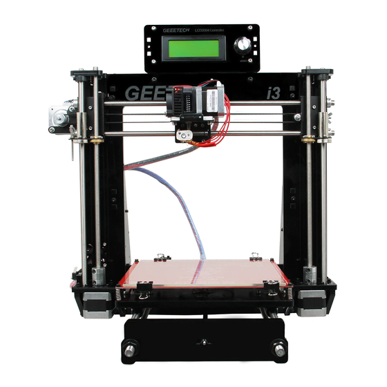
GEEETECH INTRODUCTION: This Acrylic I3 Pro B 3D printer is designed and manufactured by Shenzhen Getech Co., Ltd based on the Reprap Prusa I3, Geeetech I3 features simple assembly, easy debugging and more stable performance. The acrylic structure makes the printer much easier to operate.
-
Page 6
GEEETECH Name Specifications D8*L322mm Smooth Z axis D8*L390mm Smooth X axis D8*L410mm Smooth Y axis Threaded M8*L300mm Z-axis screw M10*L450mm Threaded Y-axis M2.5 M2.5 Washers Washers Washers Washers — 5 -… -
Page 7
GEEETECH M2.5 Lock nut Lock nut Wing nut Square nut Φ8(tin-bronze) Z-axis nut — 6 -… -
Page 8
GEEETECH Spring washer Screw locking Φ8 ring M2.5×8 mm Screw Screw M2.5×16 mm M3x6mm Screw M3x8mm Screw M3x10mm Screw M3x12mm Screw M3x16mm Screw M3x20mm Screw M3x30mm Screw M3x35mm Screw Screw M3x40mm M4x6mm Screw M4x25mm Screw — 7 -… -
Page 9
GEEETECH countersunk Bolts head bolt M3x16mm Spring LM8UU LM8UU Linear Bearings LM8LUU LM8LUU Linear Bearings Linear Bearing — 8 -… -
Page 10
GEEETECH L1=775(Y axis) Timing Belts L1=860mm(X Timing axis) Belts Bearing metal plate holder Belt Aluminum plate mount 5-8mm Couplings Pulleys 20 tooth d5mm — 9 -… -
Page 11
GEEETECH Driving wheel MR84zz Ball (Placed in bearing No.45) With Aircraft type Spacer Dovetail clamp 9*10*5mm Heat sink Sticker — 10 -… -
Page 12
GEEETECH Belt bracket Knob For LCD 40x40x10mm DuPont 3-Pin cable Male-Female USB Cord — 11 -… -
Page 13
GEEETECH End stop blue / red / black 3D Power 3*0.75 Square Cable mm Switch Line Power Control board Cable power input With heating Heat bed wire and Thermo- wire — 12 -… -
Page 14
GEEETECH Borosilicat e glass Input: 115V/1.5A 230V/0.75A Power Output : supply DC12V/0-15A Stepper motor Extruder MK8 extruder 1set Control GT2560+4 board A4988 — 13 -… -
Page 15
GEEETECH LCD 2004 LCD2004 Nylon ties Coil Acrylic kits XZ frame I3-01 Left side I3-02 frame — 14 -… -
Page 16
GEEETECH Right side I3-03 frame Z motor I3-04 fixed plate Z motor I3-05 fixed plate Z motor I3-06 support plate Z motor I3-07 support plate — 15 -… -
Page 17
GEEETECH Z top mount I3-08 Front support plate A of screw I3-09 and smooth Front support plate B of screw I3-10 and smooth Rear Support plate A of I3-11 screw and smooth rod — 16 -… -
Page 18
GEEETECH Rear support plate B of I3-12 screw and smooth rod Y motor I3-13 fixed plate Y plate for connecting I3-14 plate Y platform I3-15 support plate Y bearing I3-16 limit block Fix the LCD Acrylic panel washer — 17 -… -
Page 19
GEEETECH LCD2004 frame LCD2004 frame holder Plastic Parts X-axis left left end X-axis Right right end Print PI3-S07 bracket — 18 -… -
Page 20
GEEETECH Bearing PI3-08 Bracket Extruder PI3B-S01 bracket Free add-on Ejector File Screw driver kit — 19 -… -
Page 21
GEEETECH Filament holder Starter About 3 meters filament *The acrylic plate for the spool holder and the LCD frame are 5mm. — 20 -… -
Page 22: General Care And Maintenance
Don’t leave your printer in shady and moist places, which may exacerbate the problems associated with erosion. The three axes of the GEEETECH I3 Pro B are lubricated with grease for smooth operation and can last for a long time.
-
Page 23
GEEETECH SUPPROT Thanks for choosing Geeetech, we strive to provide a satisfied and pleasant shopping experience for you, but we do understand there may be some questions you may encounter in using our product. If so, you can contact us directly or post on our forum, our technique staff will help you resolve it. -
Page 24
GEEETECH GEEETECH www.geeetech.com — 23 -…
This manual is also suitable for:
I3 pro b

Acrylic Geeetech I3 Pro B
3D Printer

GEEETECH
Copyright Declaration
The copyright of this manual belongs to the Shenzhen GETECH CO., LTD. (hereinafter referred to as the «Geeetech»), and all rights reserved. No part of this specification should be reproduced or extracted in any forms or means without the prior written consent of Geeetech by any company and individuals.
Technical Support
If you are interested in the technology of 3 D printing, flight control and U-home, welcome to Geeetech, we have series of made-up products, main boards, modules and a variety of peripherals for you. Or if you are looking for relevant information or technical support, please log in our Forum where you can find anything you want about open source. To know more about our new products, please visit www.geeetech.com, we will serve you wholeheartedly.
— 1 —

GEEETECH
SAFETY INSTRUCTIONS
Building the printer will require a certain amount of physical dexterity, common sense and a thorough understanding of what you are doing. We have provided detailed instructions to help you assemble it easily, please download at geeetech.com.
However ultimately we cannot be responsible for your health and safety whilst building or operating the printer, with that in mind be sure you are confident with what you are doing prior to commencing with building or buying. Read the entire manual to enable you to make an informed decision.
Building and operating involves electricity, so all necessary precautions should be taken and adhered to, the printer runs on 12V supplied by a certified power supply, so you shouldn’t ever have to get involved with anything over 12V but bear in mind there can still be high currents involved and even at 12V they shouldn’t be taken lightly.
High temperatures are involved with 3D Printing, the Extrusion
— 2 —

GEEETECH
nozzle of the hot end can run about 230°C, the heated bed runs 110°C and the molten plastic extruded will initially be at around 200°C, so special care and attention should be made when handling these parts of the printer during operation.
We wouldn’t recommend leaving your printer running unattended, or at least until you are confident to do so. We cannot be held responsible for any loss, damage, threat, hurt or other negligent result from either building or using the printer.
— 3 —

GEEETECH
INTRODUCTION:
This Acrylic I3 Pro 3D printer is designed and manufactured by Shenzhen Getech Co., Ltd based on the Reprap Prusa I3, Geeetech I3 features simple assembly, easy debugging and more stable performance. The acrylic structure makes the printer much easier to operate.
PACKAGE LIST:
This list includes all the parts required to assemble your Acrylic Frame Geeetech I3 Pro 3D Printer. After you received your package, please check if all the parts listed are included. Also make sure all the components are in good condition and not damaged during shipping. If anything is missing please contact with our customer service straight away, provide us the NO. , Name, and Qty.
— 4 —

GEEETECH
|
No |
Name |
Specifications |
Qty |
Pic |
|
1 |
Smooth |
D8*L322mm |
2 |
|
|
Rod |
Z axis |
|||
|
2 |
Smooth |
D8*L390mm |
2 |
|
|
Rod |
X axis |
|||
|
3 |
Smooth |
D8*L410mm |
2 |
|
|
Rod |
Y axis |
|||
|
4 |
Threaded |
M8*L300mm |
2 |
|
|
Rod |
Z-axis screw |
|||
|
5 |
Threaded |
M10*L450mm |
2 |
|
|
Rod |
Y-axis |
|||
|
6 |
M2.5 |
M2.5 |
5 |
|
|
Washers |
||||
|
7 |
M3 |
M3 |
115 |
|
|
Washers |
||||
|
M4 |
||||
|
8 |
Washers |
M4 |
5 |
|
|
M10 |
M10 |
12 |
||
|
9 |
||||
|
Washers |
||||
— 5 —

GEEETECH
|
10 |
Nut |
M2.5 |
4 |
|
|
11 |
Nut |
M3 |
35 |
|
|
12 |
Nut |
M4 |
6 |
|
|
13 |
Nut |
M10 |
12 |
|
|
14 |
Lock nut |
M3 |
5 |
|
|
15 |
Lock nut |
M4 |
5 |
|
|
16 |
Wing nut |
M3 |
6 |
|
|
17 |
Square nut |
M3 |
34 |
|
|
18 |
Z-axis nut |
Φ8 tin-bronze |
2 |
|
— 6 —

GEEETECH
|
19 |
Spring |
M10 |
6 |
||
|
washer |
|||||
|
Screw |
|||||
|
20 |
locking |
Φ8 |
8 |
||
|
ring |
|||||
|
21 |
Screw |
M2.5×8 mm |
2 |
||
|
22 |
Screw |
M2.5×16 mm |
4 |
||
|
23 |
Screw |
M3x6mm |
25 |
||
|
24 |
Screw |
M3x8mm |
2 |
||
|
25 |
Screw |
M3x10mm |
15 |
||
|
26 |
Screw |
M3x12mm |
24 |
||
|
27 |
Screw |
M3x16mm |
32 |
||
|
28 |
Screw |
M3x20mm |
32 |
||
|
29 |
Screw |
M3x30mm |
14 |
||
|
30 |
Screw |
M3x35mm |
5 |
||
|
31 |
Screw |
M3x40mm |
5 |
||
|
32 |
Screw |
M4x6mm |
4 |
||
|
33 |
Screw |
M4x25mm |
2 |
||
— 7 —
 Loading…
Manual, Assemble Instruction for Geeetech Acrylic Prusa I3 Pro B 3D Printers (82 pages)
File Specifications:1587/1587880-acrylic_prusa_i3_pro_b.pdf file (15 Aug 2023) |
Accompanying Data:
Geeetech Acrylic Prusa I3 Pro B 3D Printers PDF Assemble Instruction (Updated: Tuesday 15th of August 2023 02:39:07 AM)
Rating: 4.1 (rated by 54 users)
Compatible devices: A30, Acrylic I3 Pro, I3 X, A30T, DP200, A10M, GCW01, acrylic Prusa I3.
Recommended Documentation:
Manual, Assemble Instruction (Text Version):
(Ocr-Read Summary of Contents of some pages of the Geeetech Acrylic Prusa I3 Pro B Document (Main Content), UPD: 15 August 2023)
-
Geeetech Acrylic Prusa I3 Pro B User Manual
-
Geeetech Acrylic Prusa I3 Pro B User Guide
-
Geeetech Acrylic Prusa I3 Pro B PDF Manual
-
Geeetech Acrylic Prusa I3 Pro B Owner’s Manuals
Recommended: Xsight Plus, Electone FX-1, Galaxy Note PRO, 620BT, M-335 TV
Links & Tools
-
Einstart®-C User ManualAdd: NO.1398 XIANGBIN RD. WENYAN XIAOSHAN, HANGZHOU, 311258, CHINA Website:www.shining3d.comwww.3dker.cnEinstart®-CUSER MANUALHANGZHOU SHINING3D TECH CO., LTD.STOCK CODE:830978 …
einstart-c 21
-
VJ-426UFOperations and Maintenance MethodsOperation Manual• Unauthorized copying or duplication of the whole or part of the contents of this manual is prohibited.• Every care has been taken in writing the contents of this manual, but please contact MUTOH or the dealer you purchased the product from if you fin …
VJ-426UF 118
-
CNC worktable3D printing worktableCNC PROMilling ToolheadPlastic Extruder3.00 mmLaser PRO ToolheadPlastic Extruder1.75 mmThick Paste ExtruderDual PROToolheadsupport.zmorph3d.comProduct ManualZMorph VX Mooltitool 3D Printer …
VX 163
-
Manual Pro2 Series — How to Install Extruder Side Cooling Fan -v1.0* The steps of replacing both sides of cooling fans are similar with each other. Here we usethe right side as reference. 1. PreparationUnload the filament from both nozzles. Turn off the printer after filament being removed. 2. Remove Fan DuctR …
PRO2 Series 8
Operating Impressions, Questions and Answers:
1 Assemble Instruction of Geeetech Acrylic Prusa I3 Pro & pro B Version
2 Safety Instructions Shenzhen GETECH CO.,LTD Building the printer will require a certain amount of physical dexterity, common sense and a thorough understanding of what you are doing. We have provided this detailed instruction to help you assemble it easily. However ultimately we cannot be responsible for your health and safety whilst building or operating the printer, with that in mind be sure you are confident with what you are doing prior to commencing with building or buying. Read the entire manual to enable you to make an informed decision. Building and operating involves electricity, so all necessary precautions should be taken and adhered to, the printer runs on 12V supplied by a certified power supply, so you shouldn t ever have to get involved with anything over 12V but bear in mind there can still be high currents involved and even at 12V they shouldn t be taken lightly. High temperatures are involved with 3D Printing, the Extrusion nozzle of the hot end can run about 230 C, the heated bed runs 110 C and the molten plastic extruded will initially be at around 200 C, so special care and attention should be made when handling these parts of the printer during operation. We wouldn t recommend leaving your printer running unattended, or at least until you are confident to do so. We cannot be held responsible for any loss, damage, threat, hurt or other negligent result from either building or using the printer. 1
3 Preparation Shenzhen GETECH CO.,LTD 1. Unpack the kit and check if all parts are in the box and check the condition of each part, there might be some damage during shipping. To help you with this, there is BOM in the box and each bag was labeled with part number. 2. Contact our customer service immediately by or through the website if you find any missing or damaged parts. And on the bottom of the BOM, there is a signature of reviewer, please take a picture of it and attach the picture in your mail. 3. Read through each chapter of these instructions to gain an over-all idea of what is involved and how long it might take, before starting on the work described. 4. Before you start, you can put all the part in order to save your time especially those screws and nuts. Do not mix them up. 5. Ensure you have the necessary skills to carry out the work, or enlist the help of someone who does. 6. Work on a big firm table or bench in a clean dry well-lit area. 7. This kit contains tiny parts; please keep them away from kids under Ask for help if you run into any problems — our contact details are on the website and we will always do our best to resolve any problems encountered. 2
4 1 Unfold the box and check the package Unfold the package and take all the parts out to check the condition of the items. As you can see, all the parts are packed very carefully. 3
5 All the acrylic plate has been etched with part ID and the plate is covered with a sheet of Kraft paper, you need to tear them off. 4
6 Tips: Shenzhen GETECH CO.,LTD 1. Before assembly, you are advised to put all the parts, especially the screws and nuts in order, which will save you a lot of time looking for the required parts. 2. The part ID is corresponding to the number labeled on the bag of every part. Some parts may not have label, you can refer to the pictures on the package list. 2 Assemble the rods of a Y axis Step1. Assemble the 2 threaded rods. Required parts Required number Part ID Pic M10 threaded rod 2 NO.5 Y plate connecting plate 2 NO.A14 M10 spring washer 6 NO.19 M10 washer 8 NO.9 M10 nut 8 NO.13 Thread the nuts and washers into the two M10 threaded rods separately. The order should be: 1) Thread the acrylic fender (Y plate connecting plate) in the middle. 2) Thread the M10 washer > M8 spring washer >M10 nut > M10 nut > M10 washer on the left 5
7 3) Thread them10 washer < M8 spring washer < M10 nut < M10 nut< M8 spring washer < M10 washer on the right 6
8 Step2. Assemble the 2 smooth rods Required parts Required number Part ID Pic M8 smooth rod 2 NO.2 LM8UU Linear 4 NO.36 bearings Slide 2 bearings on each smooth rod. Before you slide the bearings please make sure they are clean. 7
9 3 Attach the front and rear Acrylic support plates of the rods. 8
10 Required parts Required number Part ID Pic Acrylic plate( front) 2 NO. A9, A 10 Acrylic plate( rear) 2 NO. A 11, A 12 M10 washer 4 NO.9 M10 nut 4 NO.13 locking ring 2 NO.20 For some of the kit, the locking rings are the silver color, which will not affect the assembly here, but in some steps, for the X axis, there is difference, please pay attention to the note. Step1.Slide the locking ring on the smooth rods, thread the rods into the acrylic plate; adjust the length so that the smooth rods fit snugly between the front and rear piece. Step2. Screw up the rods and plate with M10 nut and M10 washer. 9
11 * Tips: Try to keep the rods parallel and the four acrylic pieces parallel. The Y-axis must be a rectangle, that is the rods on both side should be parallel, so is the front and back plate. Otherwise it will cause obstruction for the belt later. You can use a Digital Caliper to measure. *Note: As we re-designed the rear plate, there are two more holes on A12, in this case, you need to use the screw locking ring to fix the smooth rod. 4 Assemble the Y idler Required parts Required number Part ID Pic Ball bearing 2 NO.46 bearing holder 1 NO.41 10
12 Driven wheel 1 No.45 M3 x 20 screw 1 NO.28 M3 wing nut 1 NO.16 M4 x25 screw 1 NO.33 M4 lock nut 1 NO.15 Step1. Thread the M3 x 20mm screw through the bearing holder. 11
13 Step2. Insert the two MR84zz ball bearings into both ends of the driving wheel. For your convenience, this step is already finished by us. 12
14 Step3. Put the M4 x25 screw and M4 washer through the driving wheel. Lock the other end with a M4 lock nut. You may need a wrench to tighten locking nut. 13
15 14
16 *Do not screw it too tight, you should leave enough room for the wheel to turn freely. Step4. Mount the assembled bearing holder onto the front support plates from inside to outside. And screw it with a wing nut. 15
17 5 Mount the Y motor Required parts Required number Part ID Pic Y motor fix plate 1 NO. A13 16
18 Stepper motor 1 NO.62 Pulley 1 NO.44 M3 x 12 screw 3 NO.26 M3 x 16 screw 2 NO.27 M3 square nut 2 NO.17 Note: In some picture, the pulley is a bit different but it won t affect your assembly. Step1. Mount the pulley on the motor shaft, one of the screws should be screwed on the cross section of the shaft. Screw it as tight as possible. 17
19 Step2. Then screw the motor on the Y motor holder with 3 M3 x 12 screws and M3 washers. 18
20 Step3. Push the Y Motor holder tab into the square hole in Rear -Outside Plate and Rear — Inside Plate. You may need to use a little force, but be careful not to break or crack any of the Acrylic pieces. Secure the Y Motor holder with 2 M3x20mm screws, M3 Washers and M3 Square Nuts. 19
21 6 Build the printing platform Required parts Required number Part ID Pic Y platform support 1 NO.A15 Y bearing block 4 NO.A16 Belt mount 1 NO.42 20
22 Nylon tie 4 NO.66 M3 x 10 screw 2 NO.25 M3 x 20 screw 8 NO.28 M3 nut 8 NO.11 Step1. Mount the belt mount on the bottom side of the platform with 2 M3 x 10 screws. Step2. Mount the 4 bearing blocks on the platform with M3 x 20 screws on the same side with the belt-mount. Screw with M3 nuts. 21
23 Step3. Get the build platform plate zip-tied to the 4 linear bearings of Y- Axis. *The belt-mount and the fenders are under the platform. 22
24 7 Mount the Y axis belt. Required parts Required number Part ID Pic Timing belt 1 NO.39 M3 x 10 screw 2 NO.25 M3 washer 2 NO.7 Step1. Drill a hole on one end of the belt(the hole can be as the diameter of the M3 screw, leave enough margin ) Step2. Fix the belt on one side of the belt -mount with a M3 x 10 screw and washer. Step3. Thread the belt around the pulley on the motor and the Y idler. Step4. Drill a hole on the other end of the belt and fix it on the belt -mount with a M3 x 10 screw and M3 washer. 23
25 *Tips: Shenzhen GETECH CO.,LTD 1. before you drill your second hole, make sure to pull belt tightly to make sure to find proper placement of hole for a tight belt, if it is too loose, it will hinder the move of t he print platform. 24
26 8 mount the End stop of Y-axis Required parts Required number Part ID Pic End stop 1 NO.56 M2.5 x 16 screw 2 NO.22 M2.5 Hex nut 2 NO.10 Mount the end stop on the rear support plate of Y axis with M2.5 X 16 screw and M2.5 Hex nut. 25
27 9 Assemble the right and left side panel Required parts Required number Part ID Pic XZ frame 1 NO.A1 Acrylic left frame 1 NO.A2 Acrylic right frame 1 NO.A3 M3 x 16 screw 6 NO.27 26
28 M3 square nut 6 NO.17 Step1. Screw up the X-Z frame and the side panel with M3 x 16 screws and M3 square nuts. 10 Mount the fan 27
29 Required parts Shenzhen GETECH CO.,LTD Required Part ID number Pic Fan 1 NO.53 M3 x 30 screw 4 NO.29 M3 locknut 4 NO.14 Fix the fan on the right side of the frame with 4 M3 x 30 screw and lock nut. Mind the direction of the wires. (Please pay attention to the direction of the fan) If you don t want to use the lock nut you can use hex nut. 28
30 11 Assemble the Z-axis bottom mount Required parts Required number Part ID Pic Z Motor fixed plate 1 NO.A4 Z Motor fixed plate 1 NO.A5 29
31 Z Motor support plate 3 NO.A6 Z Motor support plate 1 NO. A7 M3 x 16 screw 10 NO.27 M3 square nut 10 NO.17 Step1. It would be easier to mount the A4/A5 to A6 and A7 first, and then mount the assembled part to A1. Step2.Screw up the acrylic plates with M3 x 16 screws and M3 square nuts. *The right and left bottom mount are different; Please look at the following picture. 30
32 left right 31
33 12 Assemble Y — Z axis Shenzhen GETECH CO.,LTD Required parts Required number Part ID Pic M3 x 16 screw 2 NO.27 M3 x 20 screw 4 NO.28 M3 nut 4 NO.11 M3 square nut 2 NO.17 Step1. Put the Y axis into the main frame. Step2. Screw up the main frame to the acrylic fender with 4 M3 x 20 screws. And 32
34 screw up the M10 nuts. Shenzhen GETECH CO.,LTD Step3. Screw up the Y axis rear plate and the side panel with M3 x16mm screws and M3 square nuts. 33
35 13 Mount the End stop of Z-axis Shenzhen GETECH CO.,LTD Required parts Required number Part ID Pic End stop 1 NO.56 M 2.5 X 16 screw 2 NO.22 M 2.5 nut 2 NO.10 Mount the endstop on the outside of A7 with M2.5 x 16mm screw and M2.5 hex nut. 34
36 14 Assemble the 2 Z motors Shenzhen GETECH CO.,LTD Required parts Required number Part ID Pic Stepper Motor 2 NO.62 M3 x 12screw 8 NO.26 Step1.Thread the wires of the motors through the holes Step2. Screw up the motors with 4 M3 x 12 screws. Do the same with the other Z motor. 35
37 15 Assemble the coupling. Required parts Required number Part ID Pic Couplings 2 NO.43 Step1. Fix the two couplings on both of the motor shaft. Please note: 1. The opening of both end, one is 5mm, another is 8mm, connect the 5mm hole to the motor shaft. 2. Screw the small bolt of the 5mm part on the upper part of the flat side of the motor shaft tightly. 36
38 37
39 16 Attach he heated bed. Required parts Required number Part ID Pic Heat bed set 1 NO.59 M3 x35 screw 4 NO.30 M3 washer 12 NO.7 Spring 4 NO.35 clamp 4 NO.48 38
40 Wing nut 4 NO.16 Borosilicate glass 1 NO.60 *All our heated bed is pre-soldered or attached before shipping; you can attach the bed directly here. Mount the heat bed on the platform with 4 M3 x35 screws and wing nuts with springs in between. Clamp the heat bed and the glass sheet. *the soldered side is better to be attached downwards. 39
41 17 Mount the X-axis motor end Part name Part ID Required number pic Z-axis nut No.18 1 X-axis motor end No.M1 1 Linear Bearing LMH8LUU No M3 x 30 screw No
42 M3 x 6mm screw No M3 washer No. 7 2 \ Spring No Step1. Mount the Z nut on the X-axis left end from bottom to up, fix with M3 x 6mm screws. Step2. Mount the linear bearing on X-axis motor end from bottom to up. Fix it up with M3 x 6mm screws. Mount the endstop trigger 1. Thread a M3 washer> spring> M3 washer in order to the M3x30mm screw. 2. Thread half of the M3x30mm screw into the screw hole. Mount the X motor 41
43 Part name Part ID Required number pic M3 x 6 mm screw No Stepper motor No.62 1 Pulley No.44 1 Note: In some of the picture, the pulley is a bit different but it won t affect your assembly. Step1. Mount the pulley on the motor shaft. Screw it on the flat side. Step2.Mount the stepper motor on the motor end with 3 M3 x 6 mm screw. 42
44 Mount the endstop 43
45 Part name Part ID Required number pic M2.5 x 8 mm screw No End stop No.56 1 Mount the endstop on the top of X-axis motor end with two M2.5 x 8mm screws 44
46 18 Assemble the right end of the X axis. (X idler end) For the whole process of assembly of this part, please refer to the video here. Part name Part ID Required number pic Z-axis nut No.18 1 X-axis idle end No.M2 1 Linear Bearing No LMH8LUU 45
47 M3 x 6mm screw No Step1.Mount the Z axis nut on the bottom of X-axis right end with 4 M3 x 6mm screws. Step2. Mount the linear bearing on X-axis motor end from bottom to up. Fix it up with M3 x 6mm screws. 46
48 47
49 19 Assembly of the extruder carriage Part name Part ID Required number pic X Carriage No.M3 1 Bearing Bracket No.M4 4 Extruder holder No.M5 1 Linear Bearing LM8LUU No.37 2 Belt bracket No.51 1 M3x6mm screw No M3x12mm screw No M4x6mm screw No M3 nut No.11 2 Step1. Fix the 4 Bearing Brackets on the back of the X Carriage loosely with M3x6mm screws. Insert the linear bearing into the slot and screw the bracket tightly. 48
50 Please notice the front and back of the plate. Step2. Fix the belt mount on the back of the carriage with 2 M3x 12mm screws and M3 hex nuts. Step3. Fix the extruder holder on the front side of the X carriage using M4x6mm screws. 49
51 20 Assemble the X&Z axis Part name Part ID Required number pic L300mm threaded rod L322mm smooth rod L410mm smooth rod locking ring No.4 2 No.1 2 No.3 2 No
52 Step1. Thread the L300 threaded rod to the nut of both end of X axis. Keep both end of X axis at the same place of the rod, you are advised to measure the distance of the both side so that they are at the same level when you put them up. Step2. Plug the threaded rod on the X motor end to the left coupling on the left bottom of the Z axis. Then thread the 320mm smooth rod into the linear bearing. 51
53 Step3. Thread the L410mm smooth rod into the X motor end > thread the extruder carriage on the two rods. 52
54 Step4. Thread the two X axis smooth rods into the hole of X idler end. Plug the vertical threaded rod into the coupling on the right bottom of the Z axis. Then thread the 340mm smooth rod into the linear bearing. 53
55 Note: the smooth rods and the threaded rod of Z axis are vertical and the X axis is horizontal, which is very important, or it will hinder the move of the Z axis. Step5. Fix the locking rings on the end of the rod if you got the silver rings. 54
56 NOTE: If you got the black lock ring (No.20), you need to fix all the 4 locking rings on the right end, as shown on the following picture. 55
57 21 Assemble the Z axis top mount Part name Part ID Required number pic Z top mount No.A8 2 M3 x 16mm screw No.27 4 M3 Square nut No.17 4 locking ring No
58 M3 washer No. 7 6 \ Step1. Put the locking ring on the two smooth rods separately. Step2. Add the Z top mount (No.A8) to the top of A1. Slowly rotate the rods into the holes, or add some lubricants on the rods. Do not force it, or u will break the acrylic piece. Step3. Screw it up with M3 x 16mm screw and M3 Square nut. Step4. Screw up the locking ring on smooth rods. 57
59 22 Mount the extruder Required parts Required Number Part ID Pic MK8 extruder 1 NO.63 M4 x 6mm screw 2 NO.32 M4 washer 2 NO.8 Step1. Mount the assembled extruder on the extruder support. Use 2 M4 x 6 mm screws and M4 washers to fix. 58
60 23 X belt driving wheel Part name Part ID Required number pic Driven wheel holder No.41 1 Driven wheel No.45 1 MR84zz Ball Bearing No.46 2 M3 x40mm screw No.31 1 M4 x 25mm screw No.33 1 M3 washer No
61 M4 washer No.8 1 M4 lock nut No.15 1 wing nut No.16 1 Step1. Thread the M3 x 40 screw and M3 washer through the Driven wheel holder. Step2. Insert the two MR84zz ball bearings into both ends of the driving wheel. For your convenience, this step is already finished by us. 60
62 61
63 Step3. Put the M4 x25 screw and M4 washer through the driving wheel. Lock the other end with a M4 lock nut. You may need a wrench to tighten locking nut. 62
64 *Do not screw it too tight, you should leave enough room for the wheel to turn freely. 24 Add the belt Part name Part ID Required number pic Timing belt No.40 1 Step1. Insert one end of the belt in the groove. Pay attention to the tooth mesh of the belt and the groove. Step2. Thread another end of the belt through the X motor end around the pulley. Step3. Threaded the belt through the belt driving wheel and put the driving wheel into the X idler end, lock it with a wing nut. Step4. Insert another end of the belt into the groove. Cut the spare part. Be sure of the length of the belt. Step5. Taut the belt and tighten the wing nut on the idle end. 63
65 64
66 65
67 *Note the direction of the driving wheel, the side with bolt head should be towards the A1, or it will scratch the acrylic plate. 25 Mount the LCD panel frame. Required parts Required number Part ID Pic LCD NO.65 LCD frame 1 NO.A18 LCD frame holder 2 NO.A19 Acrylic washer 4 NO.A17 M3 x 20 screw 6 NO.28 M3 nut 4 NO.11 Knob 1 NO.52 66
68 67
69 68
70 26 Mount the PSU Shenzhen GETECH CO.,LTD Required parts Required number Part ID Pic Power supply 1 NO.61 M3 x 10 screw 3 NO.25 M3 x 16 bolt 2 NO.34 M3 nut 2 NO.11 3D Power cable 1 NO.57 Power Cable 1 NO.58 Step1. Take off the wires connected to the socket; before you do, please take a photo of the wire connection, in case you connect them wrongly later. 69
71 70
72 71
73 Step2. Mount the socket on the bottom of the right side panel with 2 M3 x 16 Hex Counter- sunk-head screws and M3 hex nut. Step3. Thread the wires out. Step3. Mount the PSU (Power supply unit) on the right side panel with 3 M3 x 10 72
74 screws. Shenzhen GETECH CO.,LTD Step5. Now we can connect the wires to the PSU. 1) Mind the color of the wires. The wrong connection of the wire will cause serious damage to the PSU and even to the control board of the printer. As you can see, there are 7 wires and 7 screws in total. Note the correspondence between the color of wires and the connector. Brown——L Blue N Yellow GND Red V Black——COM 73
75 2) Pay attention to the switch on the right side of the PSU, there are two options of voltage: 110 V and 220V, choose according the standard in your country. As shown in the following picture. Remove the yellow paper; you can use some hard sticks to reach the switch. 74
76 Close the cover of the connector in case any electric shock. 27 Mount the control board Part name Part ID Required number pic Control board kit No.64 1 Sticker No.50 1 Heat sink No.49 1 Spacer No.47 4 M3 x 12 mm screw No.26 4 Step1. Cut the sticker into small pieces. Step2. Past the heat sink onto the chip of the A4988 drivers (on the main board). The sticker is double sided adhesive. Step3. Insert the spacer into the holes of the board from back to front, Mount the board kit on the left side panel with 4 M3 x 16mm screws and M3 washers on the side panel. Note the direction of the board; the green connectors are downwards to get enough heat dissipation from the fan. 75
77 28 Wiring GT2560 Before you start wiring, please take a look at the wiring schematics. 76
78 You can see original picture here. Step1. The subdivision of stepper motor can be setup by jumper cap, plug all the jumper caps (For A4988) 77
79 If you are using DRV8825 instead of A4988, the jumper caps should be changed as follow: Note please, as your printer is single extruder, you will not use the extruder 2. 78
80 Step2. Plug the 4 A4988 into the stepper motor driver slot. Mind the directions of A
81 If you are using DRV8825 instead of A4988, The correct connections are as follow: For your convenience, the above two steps is finished by us. you can skip them. 80
82 Step3. Connect wires for motors. 1) Connect wires for X-axis motor. Shenzhen GETECH CO.,LTD 2) Connect wires for Y-axis motor. 81
83 3) Connect wires for 2 Z-axis motors. Shenzhen GETECH CO.,LTD 82
84 4) Connect Extruder motors. You can connect the extruder to either of the motor slot. 83
85 Step4. Connect heating wires. Loosed the screws in the green terminal and put the red wires into the slot and screw it up. * There is no + and — for heating wires 1) Connect heating wires for heatbed. 2) Connect heating wires for extruder 1. 84
86 3) Connect heating wires for extruder 2. Step4. Connect wires for thermistor. 1) Connect wires for thermistor of heatbed. 2) Connect wires for thermistor of extruder 1. 85
87 3) Connect wires for thermistor of extruder 2. 86
88 Step5. Connect wires for endstop. * There is no + and — for endstop 1) Connect wires for endstop of X-axis at X-Min. 2) Connect wires for endstop of Y-axis at Y-Min. 3) Connect wires for endstop of Z-axis at Z-Min. 87
89 Step6. Connect wires for Fan. 1) Connect fan for control board at FAN3. 2) Connect fan for extruder at FAN1. 88
90 Step7. Connect wires for LCD panel. There are two cables, one is for LCD encoder, the other is for SD card, do not connect them reversed. EXP1 to LCD EXP2 to SD card BTW, do you see the small screw above the SD card reader, if the text in of the LCD phases in an out or there is only blocks on the screen, you can adjust this screw to recovery it. 89
91 Step8. Connect wires for power input. 90
92 That is all for the wiring of GT Tidy out the wires. Use the wire coil to tie put those wires together. There are holes on the acrylic plates for the wires, you can arrange them as you like. 30 Mount the filament spool. Required parts Required number Part ID Pic Filament side panel M3 x 16 screw 4 NO.27 M3 square nut 4 NO.17 91
93 PVC tube 2 The whole printer assembly work is already done. 31 Tips Before even attempting the first print it is vital that the printer is correctly calibrated. Skipping or rushing this step will result in frustration and failed prints later, so it is important to take the time to make sure the machine is correctly set up. Each machine may have its own calibration procedure and this manual will not attempt to cover all the variations. Instead here is a list of key points that should be 92
94 addressed. Shenzhen GETECH CO.,LTD Frame is stable and correctly aligned. Rods are correctly aligned Belts are taut. Driving wheel turns smoothly Bed is level in relation to the path of the extruder. Filament rolls freely from the spool, without causing too much tension on the extruder. Current for stepper motors is set to the correct level. Wires are correctly connected Couplings and pulleys are fixed tightly Firmware settings are correct including: axis movement speeds and acceleration; temperature control; end-stops; motor directions. Extruder is calibrated in the firmware with the correct steps per mm of filament. The point regarding the extruder step rate is vital. Slic3r expects that the machine will accurately produce a set amount of filament when told to do so. Too much will result in blobs and other imperfections in the print, too little will result in gaps and poor inter-layer adhesion. For how to set up the printer, please visit: To know how to set up, please refer to the user manual. 93
- Manuals
- Brands
- Geeetech Manuals
- 3D Printers
- Acrylic I3 Pro
- Assemble instruction
Hide thumbs
Also See for Acrylic Prusa I3 Pro B:
- Building instruction (114 pages)
- Assemble instruction (100 pages)
- User manual (35 pages)
,
,
1
2
3
4
5
6
7
8
9
10
11
12
13
14
15
16
17
18
19
20
21
22
23
24
25
26
27
28
29
30
31
32
33
34
35
36
37
38
39
40
41
42
43
44
45
46
47
48
49
50
51
52
53
54
55
56
57
58
59
60
61
62
63
64
65
66
67
68
69
70
71
72
73
74
75
76
77
78
79
80
81
82
-
page
of
82/
82 -
Bookmarks
Advertisement
Shenzhen GETECH CO.,LTD
GEEETECH
All the acrylic plate has been etched with part ID and the plate is covered with
a sheet of kraft paper, you need to tear them off.
www.geeetech.com Tel: +86 755 2658 4110 Fax: +86 755 2658 4074 ‐ 858
Previous Page
Next Page
- 1
- 2
- 3
- 4
- 5
- 6
- 7
Advertisement
Related Manuals for Geeetech Acrylic Prusa I3 Pro B
-

3D Printers Geeetech Prusa I3 pro W Building Instruction
(114 pages)
-
3D Printers Geeetech Prusa I3 Pro C Assemble Instruction
(100 pages)
-
3D Printers Geeetech Acrylic Prusa I3 Pro C Assemble Instruction
(98 pages)
-
3D Printers Geeetech Acrylic Prusa I3 Pro Assemble Instruction
(94 pages)
-
3D Printers Geeetech Acrylic Prusa I3 Pro Assemble Instruction
(90 pages)
-
3D Printers Geeetech Prusa I3 pro W User Manual
(35 pages)
-
3D Printers Geeetech Acrylic I3 Pro B Manual
(24 pages)
-
3D Printers Geeetech I3 Pro C Manual
(24 pages)


-
3D Printers Geeetech Prusa I3 Pro W Assembly Manual
(24 pages)
-
3D Printers Geeetech Acrylic I3 Pro User Manual
(19 pages)
-
3D Printers Geeetech I3 Pro C Quick Start Manual
(24 pages)
-
3D Printers Geeetech Prusa I3 A pro User Manual
(60 pages)
-
3D Printers Geeetech Prusa I3 A pro Assembly Instructions Manual
(55 pages)
-
3D Printers Geeetech Prusa I3 A pro Manual
(16 pages)
-
3D Printers Geeetech acrylic Prusa I3 Assemble Manual
(59 pages)
-
3D Printers Geeetech Acrylic Prusa I3 Assembly Instructions Manual
Pro b (109 pages)


Related Products for Geeetech Acrylic Prusa I3 Pro B
- Geeetech Prusa I3 A pro
- Geeetech acrylic Prusa I3
- Geeetech Prusa I3 X
- Geeetech Prusa I3 M201
- Geeetech I3 Pro X
- Geeetech I3 Pro C
- Geeetech Acrylic Prusa I3 Pro C
- Geeetech A10
- Geeetech A10M
- Geeetech A10T
- Geeetech A20
- Geeetech A20M
- Geeetech A20T
- Geeetech A30
- Geeetech A30 Pro
- Geeetech A30M