-
Bookmarks
Quick Links
Series FE
Low-pressure gas regulator
Revision 00 — Edition 10/2021
USE, MAINTENANCE
AND WARNING
MANUAL
EN
Related Manuals for PIETRO FIORENTINI FE Series
Summary of Contents for PIETRO FIORENTINI FE Series
-
Page 1
Series FE Low-pressure gas regulator Revision 00 — Edition 10/2021 USE, MAINTENANCE AND WARNING MANUAL… -
Page 2
PAGE INTENTIONALLY LEFT BLANK LOW-PRESSURE GAS REGULATOR INTRODUCTION REV. 00 Use, maintenance and warning manual… -
Page 3
Training the personnel in charge is essential in order to: • properly use the equipment; • correctly apply the safety alerts and procedures recommended. Revision: 00 COPYRIGHT 2022 © PIETRO FIORENTINI S.P.A. LOW-PRESSURE GAS REGULATOR INTRODUCTION REV. 00 Use, maintenance and warning manual… -
Page 4
PAGE INTENTIONALLY LEFT BLANK LOW-PRESSURE GAS REGULATOR INTRODUCTION REV. 00 Use, maintenance and warning manual… -
Page 5
1.1 — REVISION HISTORY Revision Date Revision contents index Tab. 1.1. LOW-PRESSURE GAS REGULATOR INTRODUCTION REV. 00 Use, maintenance and warning manual… -
Page 6
CONTENTS 1 — INTRODUCTION ……………………3 1.1 — REVISION HISTORY ……………………..5 2 — GENERAL INFORMATION ………………..9 2.1 — MANUFACTURER IDENTIFICATION ………………….9 2.2 — IDENTIFICATION OF THE PRODUCT ………………….9 2.3 — REGULATORY FRAMEWORK ……………………9 2.4 — WARRANTY ………………………… 9 2.5 — ADDRESSEES, SUPPLY AND STORAGE OF THE MANUAL ………….. -
Page 7
4 — DESCRIPTION AND OPERATION ………………27 4.1 — GENERAL DESCRIPTION ……………………27 4.2 — OPERATION ……………………….28 4.3 — INTENDED USE ……………………….29 4.3.1 — ENVISAGED USE ……………………..29 4.3.2 — REASONABLY FORESEEABLE MISUSE ………………..29 4.3.3 — TYPES OF FLUIDS ……………………..29 4.4 — MODELS AND CONFIGURATIONS …………………. -
Page 8
7 — COMMISSIONING ………………….57 7.1 — GENERAL WARNINGS ……………………… 57 7.1.1 — SAFETY REQUIREMENTS FOR COMMISSIONING …………….57 7.2 — PRELIMINARY PROCEDURES FOR COMMISSIONING …………….58 7.3 — CALIBRATION OF SAFETY DEVICES …………………. 58 7.4 — COMMISSIONING THE REGULATOR ………………… 58 7.4.1 — COMMISSIONING THE REGULATOR WITH MANUAL RESET …………..59 7.4.2 — COMMISSIONING THE REGULATOR WITH AUTOMATIC RESET …………60 7.5 — PROPER COMMISSIONING CHECK …………………. -
Page 9
PIETRO FIORENTINI S.P.A. guarantees that the equipment was manufactured using the best materials, with high quality workmanship, and complies with the quality requirements, specifications and performance set out in the order. The warranty shall be considered null and void and PIETRO FIORENTINI S.P.A. shall not be liable for any damage and/or malfunctions: •… -
Page 10
Keep the manual near the equipment, in an accessible place known by all qualified technicians involved in using and running it. PIETRO FIORENTINI S.p.A. shall not be held liable for any damage to people, animals and property caused by failure to adhere to the warnings and operating procedures described in this manual. -
Page 11
2.7 — SYMBOLS USED IN THE MANUAL Symbol Definition Symbol used to identify important warnings for the safety of the operator and/or equipment. Symbol used to identify information of particular importance in the manual. The information may also concern the safety of the personnel involved in using the equipment. Obligation to refer to the manual. -
Page 12
Removing nameplates and/or replacing them with other plates is strictly not allowed. Should the plates be unintentionally damaged or removed, the customer must notify PIETRO FIORENTINI S.p.A. The equipment and its accessories are provided with nameplates (from Id.1 to Id.10). -
Page 13
Type Image LOW TEMPERATURE LABEL LABEL FOR TURKEY -30 °C TEMPERATURE LABEL LABEL FOR ROMANIA LABEL FOR SPAIN KROMS Tab. 2.5. LOW-PRESSURE GAS REGULATOR GENERAL INFORMATION REV. 00 Use, maintenance and warning manual… -
Page 14
2.8.1 — GLOSSARY FOR NAMEPLATES The terms and abbreviations used on the nameplates are described below: Label terminology Description Spain Standard Russia Poland Turkey Romania Kroms Inlet pressure range max/min Adjusted pressure Pç Slam-shut Blocco device Tripping pressure ЛЗК Макс Zaw.up. -
Page 15
2.9 — GLOSSARY OF MEASUREMENT UNITS Type of measurement Unit of measurement Description Stm³/h Standard cubic metres per hour Volumetric flow rate Scfh Standard cubic feet per hour Unit of measurement in the CGS system Pounds per square inch Pressure “wc Water column inch Pascal… -
Page 16
2.10 — QUALIFIED PROFESSIONAL FIGURES Qualified operators in charge of using and managing the equipment throughout its technical service life: Professional figure Definition Qualified operator able to: • handle materials and equipment; • carry out all the operations necessary to properly install the equipment; •… -
Page 17
3 — SAFETY 3.1 — GENERAL SAFETY INSTRUCTIONS WARNING! The equipment described in this manual is: • a device subjected to pressure in pressurised systems; • normally installed in systems carrying flammable gases (for example: natural gas). WARNING! If the gas used is a combustible gas, the installation area of the equipment is defined as a “danger zone” as there are residual risks that potentially explosive atmospheres may be generated. -
Page 18
3.2 — PERSONAL PROTECTIVE EQUIPMENT Table 3.9 shows the personal protective equipment (PPE) and its description. An obligation is associated with each sym- bol. Personal protective equipment means any equipment intended to be worn by the worker in order to protect them against one or several risks that are likely to threaten their safety or health during work. -
Page 19
3.3 — RESIDUAL RISKS NOTE! The equipment of SERIES FE does not fall within the scope of the PED 2014/68/EU directive. The risks associated with the equipment are assessed below and the principles adopted for their prevention are indicated, according to the following classification: a) Elimination and/or reduction of the risk. -
Page 20
3.3.1 — TABLE SHOWING RESIDUAL RISKS DUE TO PRESSURE WARNING! If there are any functional faults, do not operate. Immediately contact PIETRO FIORENTINI S.p.A. for the necessary directions. Effect and Risk and Hazard Event and Cause Solution and Prevention Consequence a. -
Page 21
• Deterioration of Projection of • Environments with a. The user must shut off the line and con- external surfaces. metallic and aggressive atmos- tact PIETRO FIORENTINI S.p.A. • corrosion. non-metallic phere. pressurised parts. Tab. 3.10. LOW-PRESSURE GAS REGULATOR SAFETY REV. -
Page 22
3.3.2 — TABLE OF RESIDUAL RISKS FOR POTENTIALLY EXPLOSIVE ATMOSPHERES Table 3.11 shows the conditions that can lead the pressure regulators SERIES FE to generate a potentially explosive atmosphere. The table is valid for use with natural gas with a density of no more than 0.8; for different densities, the installation and environmental conditions must also be evaluated. -
Page 23
Management measures Potentially Operating included in the use, explosive Regulatory References conditions maintenance and warning atmosphere manual • Pressure must be reduced in the system section, where the equip- The manual refers to the need to ment is installed, inside a suitably Decommissioning operate in a suitably ventilated en- ventilated room. -
Page 24
3.4 — OBLIGATIONS AND PROHIBITIONS The following is a list of obligations and prohibitions to be observed for the safety of the operator: • carefully read and understand the use, maintenance and warning manual; • check whether the downstream equipment is suitably sized according to the performance required of the regulator in the actual operating condition;… -
Page 25
Depending on the operating conditions, use and configuration required, the equipment may generate noise beyond the limits allowed by current legislation in the country of installation. For the value of the noise generated by the equipment and further information, contact PIETRO FIORENTINI S.p.A. ATTENTION! -
Page 26
PAGE INTENTIONALLY LEFT BLANK LOW-PRESSURE GAS REGULATOR SAFETY REV. 00 Use, maintenance and warning manual… -
Page 27
4 — DESCRIPTION AND OPERATION 4.1 — GENERAL DESCRIPTION The equipment is a self-operated dual-stage low-pressure regulator suitable for gaseous fluids such as: • natural gas; • GPL; • non-corrosive gases. The main elements of the equipment are specified in Tab. 4.13.: Pos. -
Page 28
4.2 — OPERATION SERIES FE equipment consists of regulators featuring: • self-operation; • low pressure suitability; • a dual regulation stage. Tab. 4.14. describes the operation of the equipment in a simplified manner: Step Description The upstream pressure (A) feeds the regulator. The first regulation stage (B) determines the first pressure reduction. -
Page 29
If no written approval is provided, use shall be considered improper. In the event of “improper use”, PIETRO FIORENTINI S.p.A. shall not be held liable for any damage caused to people or property, and any type of warranty on the equipment shall be deemed void. -
Page 30
4.4 — MODELS AND CONFIGURATIONS SERIES FE includes 4 standard models based on the nominal flow rate as specified in Tab. 4.16.: Regulator trade Nominal Minimum name flow rate input pressure 6 m³/h pds + 0.2 bar FE10 10 m³/h pds + 0.3 bar FE25 25 m³/h… -
Page 31
Inlet connection Outlet connection Type (modular connections on (modular connections on Image request) request) FE T 1 G ½” EN ISO 228/1 1 G 1” EN ISO 228/1 • 1 G 1” EN ISO 228/1 (in-line inlet) FE Q 2 G ½” EN ISO 228/1 •… -
Page 32
Some typical versions are listed below, also by way of example: NOTE! The different versions of the equipment must be: • contractually established; • set up at PIETRO FIORENTINI S.p.A. plants only Type Description In case of breakage of the working diaphragm, installing a safety diaphragm guarantees: Version •… -
Page 33
Type Description This version provides to automatically reset the safety device tripped due to excess flow (after resolving the cause that caused tripping). Excess flow, automatic NOTE! reset version The safety device is reset through a downstream gas discharge with a con- trolled flow rate not greater than 15 l/h. -
Page 34
4.5 — TECHNICAL FEATURES/PERFORMANCE NOTE! To classify the functional performance of the equipment, refer to standards UNI 11655:2016 and UNI EN 16129:2013. The main specifications can be found in Tab.4.19: Technical features Design pressure (DP) 8.6 bar Inlet pressure range 0.1 — 7 bar (on request up to 8.6 bar) Regulator capacity 6 — 50 m³/h… -
Page 35
4.6 — SAFETY DEVICES To prevent the safety devices from tripping during normal service (when there are no faults at user level): • do not exceed the maximum capacity values of the gearbox; • do not feed the gearbox with pressures lower than the minimum values specified; •… -
Page 36
4.6.2 — EXCESS FLOW LOCK-UP DEVICE NOTE! If the device trips, service will be interrupted. The excess flow lock-up device (A) is a safety device which remains in the open position under normal operating condi- tions and closes automatically and completely when the pre-set flow limits are exceeded. The device trips due to the increase in the flow rate between 110% and 150% of the guaranteed flow rate specified on the plate (see paragraph 2.8). -
Page 37
4.6.3 — RELIEF VALVE The relief valve (A) is a safety device that is used to: • automatically discharge a gas flow into the atmosphere through the exhaust conveyor (B), when the pressure detect- ed downstream exceeds a pre-set value and •… -
Page 38
4.6.4 — PRESSURE OUTLET NOTE! For an in-field check of the safety devices, a pressure outlet (A) built in the regulator or on the downstream section of the system is required. Only two types of pressure outlet can be built into the regulator: •… -
Page 39
4.6.4.1 — PROCEDURE OF USE WITH STANDARD PRESSURE OUTLET ATTENTION! The maximum operating pressure for the standard pressure outlet is 0.5 bar. To use a standard pressure outlet (A), proceed as follows: Step Action Undo the locking screw (B). Fit the rubber tube on the tang (C) making sure that the connection is sealed. Tighten the locking screw (B) making sure there are no leaks from the pressure outlet. -
Page 40
4.6.4.2 — PROCEDURE OF USE WITH PETERSON MODEL PRESSURE OUTLET ATTENTION! The maximum operating pressure for a Peterson model standard pressure outlet is 10 bar. NOTE! The pressure gauge (E) and the ring nut (D) are not included in the standard scope of supply and are sup- plied only on request. -
Page 41
5 — TRANSPORT AND HANDLING 5.1 — SPECIFIC WARNINGS FOR TRANSPORT AND HANDLING NOTE! Transport and handling must be carried out in compliance with the regulations in force in the country of installation by personnel who are: • qualified (specially trained); •… -
Page 42
PIETRO FIORENTINI S.p.A.. NOTE! PIETRO FIORENTINI S.p.A. shall not be liable for any damage to people or property caused by accidents due to failure to comply with the instructions provided in this manual. Tab. 5.23. describes the types of packaging used: Ref. -
Page 43
Weight increase from 0.15 to with fittings Tab. 5.25. NOTE! Refer to the product configurator (“sizing”) of the website PIETRO FIORENTINI S.p.A. (www.fiorentini.com) for the dimensions and weight of the equipment. LOW-PRESSURE GAS REGULATOR TRANSPORT AND HANDLING REV. 00 Use, maintenance and warning manual… -
Page 44
5.3 — EQUIPMENT ANCHORING AND LIFTING METHOD HAZARD! Using lifting equipment (if necessary) for unloading, carrying and handling packages is reserved only for skilled operators who have been properly trained (and are appropriately qualified if required by the regula- tions in force in the country of installation) and are familiar with: •… -
Page 45
5.3.1 — FORKLIFT HANDLING METHOD HAZARD! Prohibitions: • do not transit under suspended loads; • do not move the load over the personnel operating in the site/plant area. WARNING! The following is not allowed on forklifts: • carrying passengers; • lifting people. -
Page 46
Step Action Image Sollevare lentamente il carico di qualche decina di centimetri e veri carne la stabilità facendo attenzio- Inclinare il montante all’indietro (verso il posto guida) per avvantaggiare il momento ribaltante e Adeguare la velocità d ne che il baricentro del carico sia posizionato al centro delle forche di sollevamento. garantire una maggiore stabilità… -
Page 47
• do not install the equipment; • contact PIETRO FIORENTINI S.p.A. and specify the details provided on the equipment nameplate. 5.4.1 — PACKAGING DISPOSAL NOTE! Sort the various materials making up the packaging and dispose of them in compliance with the regula- tions in force in the country of installation. -
Page 48
5.5 — STORAGE AND ENVIRONMENTAL CONDITIONS WARNING! Protect the regulator from blows and impacts, even accidental, until it is installed. If the equipment needs to be stored for an extended period, the minimum environmental conditions for the intended stor- age are provided in Tab.5.29. Compliance with these conditions will guarantee the declared performance: Conditions Data Maximum storage period… -
Page 49
6 — INSTALLATION 6.1 — INSTALLATION PRE-REQUISITES 6.1.1 — ALLOWED ENVIRONMENTAL CONDITIONS WARNING! To safely use the equipment, observe the environmental conditions allowed and to the data provided on the nameplate of the regulator and any accessories (refer to paragraph 2.8 “Nameplates applied”). The installation site must be suitable for the safe use of the equipment. -
Page 50
6.1.3 — CHECKS BEFORE INSTALLATION With respect to its design pressure (DP), the equipment does not require any further safety device upstream to protect against any overpressure when, for the upstream reduction station, the maximum incidental downstream pressure is: MIPd ≤ 1.1 DP MIPd = maximum incidental downstream pressure value (for further information, see UNI EN 12186:2014). -
Page 51
WARNING! The installer must: • use the fittings and gaskets supplied with the equipment by PIETRO FIORENTINI S.p.A. • fix the swivel joints (when provided) according to the tightening torques specified by standards: NF E29-533: 2014 and NF E29-536: 2017. -
Page 52
6.3 — GENERAL INFORMATION ON THE LINE The device must be installed in the line, with the arrow on its body pointing to the gas flow direction. In the typical and most frequent installation, the following must be available: Pos. Description Pressure regulator. -
Page 53
6.4 — INSTALLATION PROCEDURES NOTE! • With natural gas or other non-corrosive gases that are not subject to recondensation, the equipment can be installed in any flow direction. • Mounting positions with outlet flow facing upwards should be avoided in installations using LPG. For information about how to mount the regulator in keeping with the available models and configurations (see paragraph 4.4. -
Page 54
UNI EN ISO 228-1). Tab. 6.33. NOTE! The warranty shall be deemed null and void and PIETRO FIORENTINI S.p.A. shall not be held liable for any damage and/or malfunctions if the fittings used during installation are not those supplied. 6.4.1 — POST-INSTALLATION INSTRUCTIONS WARNING! Make sure all connections are properly tightened to prevent any leakage during commissioning. -
Page 55
6.5 — EQUIPMENT ADJUSTMENTS NOTE! All regulators are calibrated to the values requested by the customer directly at PIETRO FIORENTINI S.p.A. factory. No further adjustments are required. The calibration values are specified on the nameplate (refer to paragraph 2.8). Adjustment Operator qualification •… -
Page 56
10 (“Calibration tables”). NOTE! The relief valve pressure does not need to be adjusted. WARNING! Contact PIETRO FIORENTINI S.p.A. for any further need. Do not make any unauthorised changes to the equipment without the approval of PIETRO FIORENTINI S.p.A. LOW-PRESSURE GAS REGULATOR INSTALLATION REV. -
Page 57
7 — COMMISSIONING 7.1 — GENERAL WARNINGS 7.1.1 — SAFETY REQUIREMENTS FOR COMMISSIONING HAZARD! During commissioning the risks associated with any discharges to the atmosphere of flammable or nox- ious gases must be evaluated. HAZARD! In case of installation on distribution networks for natural gas, consider the risk of explosive mixtures (gas/air) forming inside the piping, if the line is not subjected to inerting. -
Page 58
7.3 — CALIBRATION OF SAFETY DEVICES NOTE! The equipment is regulated at PIETRO FIORENTINI S.p.A. production plants WARNING! Do not tamper with or make any unauthorised changes to the equipment without the approval of PIETRO FIORENTINI S.p.A. -
Page 59
7.4.1 — COMMISSIONING THE REGULATOR WITH MANUAL RESET To commission the regulator (A), with and without excess flow shut-off device, proceed as indicated in Tab. 7.37.: Step Action Slowly open the shut-off valve upstream of the regulator (A) to feed it. Unscrew the protection cap (B) of the reset knob (C). -
Page 60
7.4.2 — COMMISSIONING THE REGULATOR WITH AUTOMATIC RESET To commission the regulator (A) with automatic reset, proceed as indicated in Tab. 7.38.: Step Action Slowly open the shut-off valve upstream of the regulator (A) to feed it. Unscrew the protection cap (B) of the reset knob (C). Engage the knob (C) with the cap (B) through the special built-in hook. -
Page 61
7.5 — PROPER COMMISSIONING CHECK Check the connections made during the installation of the equipment (refer to chapter 6 “Installation”) for proper sealing through a foaming solution (or equivalent control system). 7.6 — RESET OF SAFETY DEVICES AFTER COMMISSIONING HAZARD! Before resetting the safety devices, eliminate the causes that caused them to trip. -
Page 62
7.7 — DRUM ASSEMBLY (UNDERGROUND VERSION OF THE REGULATOR) NOTE! The drum must only be assembled for the underground version of the regulator. 7.7.1 — DRUM ASSEMBLED TO THE SLAM-SHUT VALVE LID NOTE! The drum must always be in a horizontal position with the camera facing the ground. After commissioning the equipment (see paragraph 7.4), proceed as indicated in Tab. -
Page 63
7.7.1.1 — REGULATOR RESET To reset the underground version of the regulator with drum fixed on the slam-shut valve lid, proceed as indicated in Tab. 7.40.: Step Action Undo the butterfly screw (1) counterclockwise. Remove the drum (3) from the brass fitting (5). Commission the equipment (see paragraph 7.4). -
Page 64
7.7.2 — DRUM FIXED ON THE SECOND STAGE CONTROL HEAD NOTE! The drum must always be in a horizontal position with the camera facing the ground. After commissioning the equipment (see paragraph 7.4), proceed as indicated in Tab. 7.41.: Step Action Unscrew the butterfly screw (1) anticlockwise, making sure that the O-ring (2) remains in its seat. -
Page 65
NOTE! The equipment does not need any periodic checks and maintenance procedures. HAZARD! PIETRO FIORENTINI S.p.A. shall not be held liable for any damage to people and property due to services provided without its approval. WARNING! If you have doubts or there are any functional faults, do not operate. Contact PIETRO FIORENTINI S.p.A. -
Page 66
8.2 — PERIODICALLY CHECKING AND INSPECTING THE EQUIPMENT FOR PROPER OPERATION HAZARD! Checks and inspections must be carried out only by qualified technicians. Periodic checks and inspections Operator qualification • Commissioning technician. WARNING! The PPE listed in this table is related to the risk associated with the equipment. PPE required For the PPE required to protect against risks associated with the workplace, installation or operating conditions, please refer to:… -
Page 67
Step Action Checking the slam-shut device for tripping due to maximum downstream pressure: 1. open the external pressure source by increasing the pressure by approximately: • 2 mbar/s for the BP version; • 5 mbar/s for the TR version; until the slam-shut device trips due to maximum pres- sure when the reset knob clicks;… -
Page 68
8.3 — TIGHTENING TORQUES NOTE! For the tightening torques of the swivel joints, refer to standards: NF E29-533: 2014 and NF E29-536: 2017. LOW-PRESSURE GAS REGULATOR FUNCTIONAL CHECKS REV. 00 Use, maintenance and warning manual… -
Page 69
9 — UNINSTALLATION AND DISPOSAL 9.1 — GENERAL SAFETY WARNINGS HAZARD! Make sure that there are no potentially explosive ignition sources in the work area set up to uninstall and/ or dispose of the equipment. WARNING! Before proceeding with uninstallation and disposal, make the equipment safe by disconnecting it from any power supply. -
Page 70
9.4 — INFORMATION REQUIRED IN CASE OF NEW INSTALLATION NOTE! Should the equipment be reused after uninstallation, refer to chapters: “Installation” and “Commission- ing”. 9.5 — DISPOSAL INFORMATION NOTE! • Proper disposal prevents damage to humans and the environment and promotes the reuse of precious raw materials. -
Page 71
10 — CALIBRATION TABLES 10.1 — CALIBRATION TABLES NOTE! When the value indicated on the regulator plate is equal to the minimum or maximum value of a spring referred to in the tables (Tab.10.49., Tab.10.50., Tab.10.51., Tab.10.53., Tab.10.54. And Tab.10.55 .), the spring installed in the regulator is the one featuring the minimum range value equal to the calibration value speci- fied on the data plate. -
Page 72
SLAM-SHUT VALVE BP FE6-10-25-S Spring range (mbar) Spring item Pos. Spring colour code Min. Max. 6447038700 64470120BLU Blue 64470121GI Yellow 64470122VE Green 36.5 64470123ROS 31.5 64470124AZ Sky blue 64470020MAR Brown d = Wire Diameter (mm) Lo = Spring Length (mm) De = External Diameter (mm) Tab. -
Page 73
SLAM-SHUT VALVE TR FE6-10-25-S Spring range (mbar) Spring item Pos. Spring colour code Min. Max. 64470169GR Grey 64470168BI White 20.2 d = Wire Diameter (mm) Lo = Spring Length (mm) De = External Diameter (mm) Tab. 10.55. RELIEF VALVE TR FE6-10-25-S Spring range (mbar) Spring item Pos.
Регуляторы серии FE (FE 6, FE 10, FE 25, FES) разработаны для установки непосредственно на расходомеры пользователей или на газопроводы для бытового использования. Они могут быть использованы в любом положении при условии защиты от атмосферного воздействия.
Внутренние защитные клапаны могут быть задействованы для наружного применения, если они установлены в замкнутых объемах, или для подземных сооружений.
Серия регуляторов FE представлена моделями в зависимости от производительности регулятора: FE6 — 6 стм3/ч, FE10 — 10 стм3/ч, FE25 — 25 стм3/ч, FES — 50 стм3/ч
Благодаря двухступенчатой и модульной конструкции регуляторы серии FE обеспечивают:
- высокую точность,
- высокую надежность в эксплуатации,
- легкость установки.
Технические характеристики
|
Класс точности |
до 5 |
|
Давление закрытия SG |
до 10 |
|
Расчетное давление |
8.6 bar |
|
Температура |
От -40*С до +60*С — Низкотемпературное исполнение |
|
Диапазон давления на выходе |
BP: 13 — 180 mbar TR: 180-500 mbar |
|
Диапазон давления на входе |
0.15-8.6 bar |
Обзор регулятора давления газа Pietro Fiorentini FE 25 L
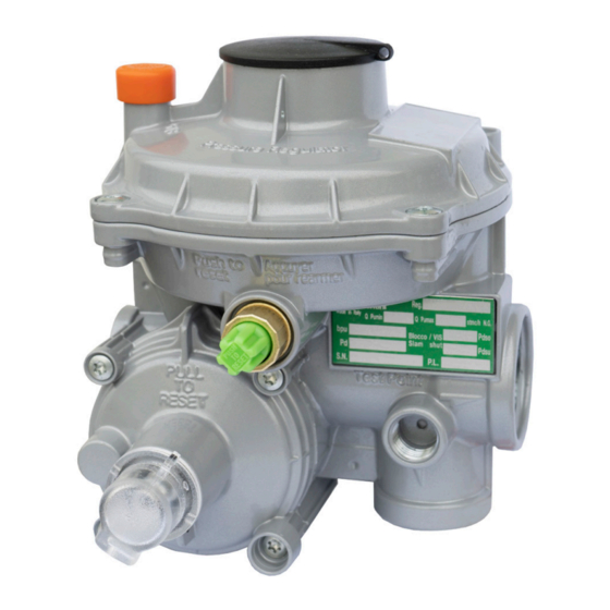
Регулятор давления газа Pietro Fiorentini FE 25 L — это двухступенчатый регулятор давления прямого действия. Может применяться как в промышленном, так и в гражданском газоснабжении.
Обзор регулятора давления газа Pietro Fiorentini FE 25 L включает основные характеристики оборудования. Прибор необходим для редуцирования природного газа, сжиженного углеводородного газа и других газообразных веществ.
В отзывах о регуляторе давления газа Pietro Fiorentini FE 25 L отмечают надежность устройства. Встроенный предохранительный сбросный клапан и предохранительный запорный клапан срабатывают при аварийном понижении или повышении давления газа на выходе. Установка регулятора производится на газовый счетчик в открытом помещении, защищенном от неблагоприятных условий погоды. Следует отметить, что при температуре ниже 0°C газ не должен содержать влагу, в противном случае оборудование может прийти в негодность и требовать ремонта. Редуктор может быть установлен в закрытом или подземном помещении, в таком случае сбросной клапан выводится наружу.
Схема подключения регулятора

Особенности регулятора давления газа Pietro Fiorentini FE 25 L
- Сбросной клапан
- Запорный клапан
- Широкий спектр применения
- Безопасность
Регулятор давления газа Pietro Fiorentini FE 25 L — купить в СПб
В нашем фирменном интернет-магазине «Мистер Климат» (mrklimat.ru) цена на регулятор давления газа Pietro Fiorentini FE 25 L составляет 16 400 руб. Для того, чтобы купить регулятор давления газа Pietro Fiorentini FE 25 L в СПб, вам достаточно оставить заявку на сайте либо по телефону. Оплатить товар можно любым удобным для вас способом: наличными или карточкой при получении, либо заранее на сайте или банковским платежом.
Доставка осуществляется собственной курьерской службой в течение 1–2 дней с момента заказа. С товаром вы получите гарантийный талон, инструкцию по эксплуатации, товарный и кассовый чек. С подробной информацией об условиях доставки можно ознакомиться в разделе «Доставка» либо уточнить все вопросы у технического консультанта по телефону.
Описание товара носит информационный характер. Производитель оставляет за собой право изменять характеристики, комплектацию, инструкцию по эксплуатации и внешний вид товара без предварительного уведомления.
Регуляторы серии FE (FE 6, FE 10, FE 25, FES) разработаны для установки непосредственно на расходомеры пользователей или на газопроводы для бытового использования. Они могут быть использованы в любом положении при условии защиты от атмосферного воздействия.
Внутренние защитные клапаны могут быть задействованы для наружного применения, если они установлены в замкнутых объемах, или для подземных сооружений.
Серия регуляторов FE представлена моделями в зависимости от производительности регулятора: FE6 — 6 стм3/ч, FE10 — 10 стм3/ч, FE25 — 25 стм3/ч, FES — 50 стм3/ч
Благодаря двухступенчатой и модульной конструкции регуляторы серии FE обеспечивают:
- высокую точность,
- высокую надежность в эксплуатации,
- легкость установки.
Технические характеристики
|
Класс точности |
до 5 |
|
Давление закрытия SG |
до 10 |
|
Расчетное давление |
8.6 bar |
|
Температура |
От -40*С до +60*С — Низкотемпературное исполнение |
|
Диапазон давления на выходе |
BP: 13 — 180 mbar TR: 180-500 mbar |
|
Диапазон давления на входе |
0.15-8.6 bar |
| Наименование | Опт | Розница |
| FE 10, 25 (20 мбар), исп S или L | 85 евро | 90 евро |
| FES (20 мбар)), исп S или L | 115 евро | 125 евро |
Двухступенчатые регуляторы давления серии FE с автономным приводом широко используются для бытовых целей и в промышленных установках, использующих природный газ, сжиженный углеводородный газ LPG и другие не коррозионные газы.
Внутренние защитные клапаны могут быть задействованы для наружного применения, если они установлены в замкнутых объемах, или для подземных сооружений.
Серия регуляторов FE представлена моделями в зависимости от производительности регулятора: FE6 — 6 стм3/ч, FE10 — 10 стм3/ч, FE25 — 25 стм3/ч, FES — 50 стм3/ч
Благодаря двухступенчатой и модульной конструкции регуляторы серии FE обеспечивают:
- высокую точность,
- высокую надежность в эксплуатации,
- легкость установки.
Технические характеристики
| Класс точности | до 5 |
| Давление закрытия SG | до 10 |
| Расчетное давление | 8.6 bar |
| Температура | От -30*С до +60*С |
| Диапазон давления на выходе | BP: 13 — 180 mbar TR: 180-500 mbar |
| Диапазон давления на входе | 0.15-8.6 bar |


Двухступенчатые регуляторы давления серии FE с автономным приводом широко используются для бытовых целей и в промышленных установках, использующих природный газ, сжиженный углеводородный газ LPG и другие не коррозионные газы. Эти регуляторы разработаны для установки непосредственно на расходомеры пользователей или на газопроводы для бытового использования. Они могут быть использованы в любом положении при условии защиты от атмосферного воздействия.
Внутренние защитные клапаны могут быть задействованы для наружного применения, если они установлены в замкнутых объемах, или для подземных сооружений. Благодаря двухступенчатой конструкции они обеспечивают: высокую точность, высокую надежность в эксплуатации и легкость установки. Эти регуляторы изготовлены в соответствии с требованиями UNI 8827.
Благодаря универсальной конструкции и надежности в работе, регуляторы серии FE завоевали популярность во всем мире. На настоящий момент установленно более 15 млн.ед..Ежегодно устанавливается порядка 1 млн. ед. регуляторов данной серии.
,Fe-10L (ARD 10L),Fe-25 (ARD 25),Fe-25L (ARD25L)") Регуляторы газа типа Fe-10 (ARD 10),Fe-10L (ARD 10L),Fe-25 (ARD 25),Fe-25L (ARD25L) предназначены для редукции давления сухого и очищенного газового топлива, распределяемого при среднем давлении. Газ, распределяемый при среднем давлении, редуцируется на низкое давление, что дает возможность использования этих редукторов в коммунальных целей.
Регуляторы газа типа Fe-10 (ARD 10),Fe-10L (ARD 10L),Fe-25 (ARD 25),Fe-25L (ARD25L) предназначены для редукции давления сухого и очищенного газового топлива, распределяемого при среднем давлении. Газ, распределяемый при среднем давлении, редуцируется на низкое давление, что дает возможность использования этих редукторов в коммунальных целей.
Эти регуляторы имеют современную компактную конструкцию и надежны в эксплуатации. Для их изготовления используются конструкционные материалы высокого качества, в том числе литье под давлением из алюминиевых сплавов, нержавеющая сталь, бронза и высокого качества пластмассы. Все этапы производственного процесса осуществляются в соответствии с процедурами системы обеспечения качества PN-ISO 9002.
Исключительное достоинство этих редукторов — их надежная работа при низких температурах (до -40°С), что подтверждается испытаниями, проведенными Институтом нефтяной и газовой промышленности в Кракове. Это предотвращает возможные последствия аварий в газовых сетях, вызванных замерзанием редукторов в зимних условиях.

Двухступенчатая система редукции давления обеспечивает высокую стабильность работы этих редукторов. Современное решение внутренних систем защиты гарантирует их эксплуатационную безопасность.
Разрешение Проматомнадзора РБ № 06-603/06
Лицензия на изготовление СЛ № 023402
ТУ 809000155.001.2002
Защита:
от падения давления в патрубках входном или выходном;
от чрезмерного роста давления газа при внезапном ограничении отбора газа;
от чрезмерного роста давления газа, вызванного неисправностью редуктора;
от механических загрязнений газа;
от конденсата;
встроенный спускной предохранительный клапан.
Установка: в любом положении.
|
Параметры |
Fe-25, ARD-25, ARD-25L |
Fe-10, ARD-10, ARD-10L |
|
Редуцируемая среда |
Природный газ по ГОСТ 5542-87 |
|
|
Температура окружающей среды, °С |
от – 40 ºС до + 60 ºC. |
|
|
Максимальное входное давление, МПа |
0,7 |
|
|
Диапазон настройки выходного давления, кПа |
0,8-8,0 |
|
|
Производитель осуществляет установку величины выходного давления, кПа |
2,0 |
|
|
Пропускная способность Q, м3/час |
||
|
Рвх, МПа |
ARD-25 (ARD-25L) |
ARD-10 (ARD-10L) |
|
0,05 |
23,70 |
9,50 |
|
0,1 |
30,07 |
12,03 |
|
0,2 |
30,50 |
12,24 |
|
0,3 |
31,00 |
12,42 |
|
0,4 |
34,50 |
13,80 |
|
0,5 |
38,70 |
15,50 |
|
0,6 |
39,70 |
15,90 |
|
Масса |
10 |
10 |
|
Срок службы, лет |
10 |
10 |
|
Параметры |
ARD-25 (ARD-25L) |
ARD-10 (ARD-10L) |
|
|
Присоединительные размеры, мм |
|||
|
входного патрубка выходного патрубка |
20 32 |
20 32 |
|
|
Габаритные размеры, мм., не более, |
Длина |
140 |
140 |
|
Ширина |
134 |
134 |
|
|
Высота |
166 |
166 |
|
|
Масса |
10 |
10 |
|
|
Срок службы, лет |
10 |
10 |
Регулятор состоит из корпуса 1, клапана редуцирования первой ступени 2, клапана редуцирования второй ступени 3, сбросного клапана 4, предохранительного запорного клапана 5. В корпус ввернута втулка 6, которая имеет седла для клапана первой ступени редуцирования и предохранительного клапана. Со стороны выхода регулятора в корпус ввернута втулка 7 в сборе с клапаном редуцирования второй ступени. В отверстие клапана редуцирования второй ступени входит рычаг 8. Второй конец рычага вставляется в отверстие рабочей мембраны 9. На мембране собран сбросной клапан 4 с пружиной настройки. Газ, поступая через входной штуцер, поступает в полость А, а затем проходит через отверстие втулки 6 и попадает в полость Б. Через отверстия в корпусе 1 и крышке 10 газ поступает в полость В. Под воздействием давления газа на мембрану 11 зазор между клапаном редуцирования первой ступени и седлом уменьшается. В полости Б происходит первое падение давления. Далее газ проходит через гнездо клапана редуцирования второй ступени и попадает в полость Г. Через импульсную трубку 12 газ поступает в под-мембранную полость Д. Воздействуя на мембрану 9, газ поднимает ее и тянет за собой рычаг 8. Второй конец рычага 8 толкает клапан редуцирования второй ступени, уменьшая зазор между клапаном и седлом. В полости Г происходит второе падение давления газа. В случае чрезмерного роста давления в полости Г газ, воздействуя на мембрану 13, освобождает защелку 14. Предохранительный клапан под действием пружины 15 перекрывает поступление газа.
Скачать схему Fe-10, ARD 10,Fe-10L, ARD 10L, Fe-25, ARD 25, Fe-25L, ARD25L

Регуляторы давления газа домовые FE10, FE25: 1 — корпус; 2 — клапан редуцирования первой ступени; 3 — клапан редуцирования второй ступени; 4 — сбросной клапан; 5 — предохранительный запорный клапан; 6, 7 — втулки; 8 — рычаг; 9, 11, 13 — мембраны; 10 — крышка; 12 — импульсная трубка; 14 — защелка; 15 — пружина; А, Б, В, Г, Д — полости
Заказать Регулятор давления газа Fe-10 (ARD 10), Fe-10L (ARD 10L), Fe-25 (ARD 25), Fe-25L (ARD25L) узнать цену, сроки поставки можно воспользовавшись формой заказа или контактной информацией. По запросу предоставим: схему, паспорт, сертификат, разрешение.
Обзор регулятора давления газа Pietro Fiorentini FE 25 L
Регулятор давления газа Pietro Fiorentini FE 25 L — это двухступенчатый регулятор давления прямого действия. Может применяться как в промышленном, так и в гражданском газоснабжении.
Обзор регулятора давления газа Pietro Fiorentini FE 25 L включает основные характеристики оборудования. Прибор необходим для редуцирования природного газа, сжиженного углеводородного газа и других газообразных веществ.
В отзывах о регуляторе давления газа Pietro Fiorentini FE 25 L отмечают надежность устройства. Встроенный предохранительный сбросный клапан и предохранительный запорный клапан срабатывают при аварийном понижении или повышении давления газа на выходе. Установка регулятора производится на газовый счетчик в открытом помещении, защищенном от неблагоприятных условий погоды. Следует отметить, что при температуре ниже 0°C газ не должен содержать влагу, в противном случае оборудование может прийти в негодность и требовать ремонта. Редуктор может быть установлен в закрытом или подземном помещении, в таком случае сбросной клапан выводится наружу.
Схема подключения регулятора
Особенности регулятора давления газа Pietro Fiorentini FE 25 L
- Сбросной клапан
- Запорный клапан
- Широкий спектр применения
- Безопасность
Регулятор давления газа Pietro Fiorentini FE 25 L — купить в СПб
В нашем фирменном интернет-магазине «Мистер Климат» (mrklimat.ru) цена на регулятор давления газа Pietro Fiorentini FE 25 L составляет 16 400 руб. Для того, чтобы купить регулятор давления газа Pietro Fiorentini FE 25 L в СПб, вам достаточно оставить заявку на сайте либо по телефону. Оплатить товар можно любым удобным для вас способом: наличными или карточкой при получении, либо заранее на сайте или банковским платежом.
Доставка осуществляется собственной курьерской службой в течение 1–2 дней с момента заказа. С товаром вы получите гарантийный талон, инструкцию по эксплуатации, товарный и кассовый чек. С подробной информацией об условиях доставки можно ознакомиться в разделе «Доставка» либо уточнить все вопросы у технического консультанта по телефону.
Описание товара носит информационный характер. Производитель оставляет за собой право изменять характеристики, комплектацию, инструкцию по эксплуатации и внешний вид товара без предварительного уведомления.