![]()
- Оборудование
- Одноканальные сигнализаторы загазованности
- Многоканальные системы контроля загазованности
- Бытовые комплекты контроля загазованности
- Бытовая система LINEA BIANCA
- Переносные газоанализаторы
- Портативные измерительные приборы
- Универсальный сенсор / Сигнализатор загазованности
- Электронные термостаты
- Термостаты для фэнкойлов
- Механические термостаты
- Радиотермостаты
- Температурные зонды
- Чувствительные элементы
- Аксессуары
- Услуги
- Поверка
- Документация
- О компании
- Новости
- Статьи
- Контакты
- Москва
- Казань
- Оренбург
- Екатеринбург
- Пермь
- Краснодар
- Новосибирск
- Санкт-Петербург
- Воронеж
- Челябинск
- Белград(Сербия)
stefano, 21 Set
Документация
1. Для проектных организаций
- Проектное решение животноводческий комплекс
- Проектное решение промышленное помещение
- Проектное решение промышленное помещение2
- Проектные решения котельные
- Проектные решения парковка
- Проектные решения парковка2
- Проектные решения частный жилой сектор
- Проектные решения частный жилой сектор2
2. Нормативная документация
- Рекомендации по размещению сигнализаторов на горючие газы
- СНиП «Котельные установки» (СП 89.13330.2012)
- Федеральный закон об обеспечении единства измерений
- Требования к установке сигнализаторов и газоанализаторов (ТУ-ГАЗ-86)
- Европейские стандарты безопасности и взрывозащищенные корпуса (Статья из журнала «Электронные компоненты» №3 2002 автор: Евгений Егоров)
- Европейская маркировка взрывозащищенного оборудования
- СП 13-108-2004 Свод правил по поквартирному отоплению
- СП 7.13130.2013 Свод правил по противопожарным требованиям
- РД БТ 39-0147171-003 Требования к установке датчиков стационарных газосигнализаторов
- СП 41-104-2000 Свод правил по проектированию автономных источников теплоснабжения
- СНиП 42-01-2002 Газораспределительные системы
3. Методики поверки
- МП-242-1183-2011 (Сигнализаторы RGDCO0MP1)
- МП-242-1354-2012 (Сигнализаторы RGDCO0MP1 с внешним сенсором SGAMET)
- МП-242-2139-2017 (Сигнализаторы загазованности комбинированные RGDCO0MP1)
- МП-242-1390-2012 (Сигнализаторы RGDMETMP1)
- МП-242-1594-2013 (Сигнализаторы RGDME5MP1 BEAGLE)
- МП-242-1760-2014 (Сигнализаторы RGD с сенсорами SGA)
- МП-242-0909-2009 (Сигнализаторы RGICO0L42 + изменение №1)
- МП-242-1389-2012 (Сигнализаторы RGI с сенсорами SGA/SGI)
- МП-242-1102-2010 (Сигнализаторы RGY000MBP4)
- МП 52457-13 (RGW032 с сенсорами SGW)
- МП-242-1745-2014 (Сигнализаторы SGY, SGW)
- МП-242-0724-2008 (Датчики горючих газов SGYME0V4ND)
- МП-242-1463-2012 (Газоанализаторы Chemist 400)
- МП-242-1464-2012 (Газоанализаторы CASPER)
- ИЦРМ-МП-009-19 (Газоанализаторы CHEMIST 100 BEE GREEN)
- МП-242-2140-2017 (Сигнализаторы SY)
4. Сертификаты, декларации и свидетельства об утверждении типа СИ
- Декларация о соответствии на сигнализаторы загазованности типов RGD, RGI, RGY и RGW
- Декларация о соответствии на газоанализаторы chemist 100BE GREEN
- Декларация о соответствии на портативные приборы
- Декларация о соответствии на термостаты
- Декларация о соответствии на сирены
- Декларация о соответствии на шлюз
- Свидетельство об утверждении типа средств измерений RGICO0L42
- Свидетельство об утверждении типа средств измерений RGW032
- Свидетельство об утверждении типа средств измерений сенсоров SGY и SGW
- Свидетельство об утверждении типа средств измерений SGYMEOV4ND
- Свидетельство об утверждении типа средств измерений серии RGD на горючие газы
- Cертификат об утверждении типа серии SY
- Сертификат об утверждении типа RGDCO0MP1 с SGAMET
- Сертификат соответствия на внешний сенсор взрывозащищенного типа SGYME0V4ND
- Свидетельство об утверждении типа средств измерений на газоанализатор CHEMIST 100 BEE GREEN
- IMQ Сертификат на сигнализаторы загазованности
- Сертификат ISO9001
![]()
Прайс лист

Контрольно измерительные приборы и средства автоматизации
КИПА AQUA

Прайс лист отопление и водоснабжение
Российское отделение фирмы Seitron S.p.A.
Copyright © 1999-2022 Seitron™. Все права защищены.
Сайт создан компанией «КИПА»
-
Contents
-
Table of Contents
-
Troubleshooting
-
Bookmarks
Quick Links
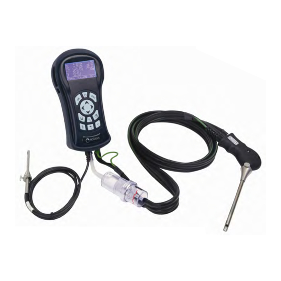
Combustion Analyzer
TÜV SÜD approved:
EN 50379-1
EN 50379-2
1.BimSchV (RgG 292)
USE AND MAINTENANCE
Respect your environment: think before printing the full manual on paper.
CASPER
Compliant with:
UNI 10845
UNI 10389-1
MANUAL
dispositivi elettronici
di regolazione, misura e controllo
Related Manuals for Seitron CASPER
Summary of Contents for Seitron CASPER
-
Page 1
CASPER Combustion Analyzer TÜV SÜD approved: Compliant with: EN 50379-1 UNI 10845 EN 50379-2 UNI 10389-1 1.BimSchV (RgG 292) USE AND MAINTENANCE MANUAL Respect your environment: think before printing the full manual on paper. -
Page 3: Table Of Contents
Important information Intended purpose INTRODUCTION General Description of the Combustion Analyser General features of the Flue Gas Analyser CASPER Main configurations TECHNICAL SPECIFICATIONS Technical Specifications Overview of Flue Gas Analyser Components Measurement and Accuracy Ranges USING THE FLUE GAS ANALYSER…
-
Page 4
ANNEX C — Flue gas analysis according to Italian Law No. 10 WARRANTY CERTIFICATE SEITRON S.p.A. — ALL RIGHTS RESERVED — Total or partial reproduction of this document by any means (including photocopying or storage on any electronic medium) and transmittal of same to third parties in any manner, even electronically, is strictly prohibited unless explicitly authorised in writing by SEITRON S.p.A. -
Page 5: Important Information
Read these operation and maintenance manual carefully before use. The professional personnel must be familiar with this manual and follow the instructions contained herein. This manual describes the operation, function and maintenance of the English version for CASPER — Flue Gas Analyzer.
-
Page 6: Intended Purpose
This chapter describes the areas of application for which the CASPER is intended. Using the CASPER in other application areas is on the risk of the operator and the manufacturer assumes no responsibility and liability for loss, damage or costs which could be a result. It is mandatory to read and pay attention to the operating/maintenance manual.
-
Page 7: Introduction
The memory can store 300 complete analyses and the data downloaded onto a PC by means of dedicated SW and a mini-USB serial communication cable. It is also interesting to note that «CASPER» has just one «Li-Ion» rechargeable battery pack used for powering the instrument; it also has a luminous and large (70 x 38 mm) LCD display boasting excellent readability thanks to its backlighting and also to the zoom function.
-
Page 8: Casper Main Configurations
1.3 CASPER Main configurations CASPER CASPER CASPER CASPER CASPER CASPER 201 S 202 S 301 S O2 SENSOR CO SENSOR NO SENSOR EXPANDABLE EXPANDABLE TO 3 SENSORS BLUETOOTH TIGHTNESS TEST DRAUGHT MEASUREMENT ACCORDING UNI 10845 CALIBRATION CERTIFICATE QUICK GUIDE FUMES PICKING PROBE…
-
Page 9: Technical Specifications
TECHNICAL SPECIFICATIONS 2.1 Technical Specifications Autozero: Manual autozero cycle (without probe inserted in the stack). Self-diagnosis: All the functions and internal functions are checked and anomalies signalled. Type of combustible: 11 predefined by the factory and 16 that can be programmed by the user. Power: Li-Ion battery pack with internal protection circuit.
-
Page 10: Overview Of Flue Gas Analyser Components
2.2 Overview of Flue Gas Analyser Components Fig. 2.2 LEGEND Keypad Display Fumes exhaust probe Condensate separator and fine dust filter unit Compensated male connector of the fumes exhaust temperature probe Combustion air temperature probe (Optional) P- connector (negative input for measuring differential pressure) A connector (fumes exhaust probe input by means of a complete condensate separator unit) P+ connector (positive input for measuring draught) Temperature Tc-K female connector…
-
Page 11
Seitron does, however, certify measurement accuracy only when a calibration certificate has been issued by its own laboratory or by an authorised laboratory. -
Page 12
A calibration certificate is provided with each and every instrument where every parameter is accompanied by the relevant nominal value, measured value, permissible error tolerances and measured error. Electromagnetic compatibility The instrument was designed to comply with Council Directive 2004/108/EC governing electromagnetic compatibility. Seitron’s declaration of conformity may be found in Annex B. K800000000SE 023942A0 080914… -
Page 13: Measurement And Accuracy Ranges
2.3 Measurement and Accuracy Ranges MEASUREMENT SENSOR RANGE RESOLUTION ACCURACY Electrochemical sensor 0 .. 25.0% vol 0.1% vol ±0.2% vol ±20 ppm 0 .. 400 ppm Electrochemical sensor 0 .. 8000 ppm 1 ppm ±5% measured value 401 .. 4000 ppm high immunity H ±10% measured value 4001 ..
-
Page 14: Using The Flue Gas Analyser
100% charge cycle by connecting the instrument to the power pack for 3 hours. If the problem persists, replace the battery pack with a SEITRON original or contact the SERVICE CENTRE to carry out the necessary repairs.
-
Page 15
THE POWER SUPPLY/BATTERY CHARGER IS A SWITCHING TYPE ONE. THE APPLICABLE INPUT VOLTAGE RANGES BETWEEN 90Vac AND 264Vac. INPUT FREQUENCY: 50-60Hz. THE LOW VOLTAGE OUTPUT IS 12 VOLT WITH AN OUTPUT CURRENT GREATER THAN 1.5A. LOW VOLTAGE SUPPLY CONNECTOR: DC PLUG 2.1×5.5×9 mm. WITH CENTRAL POSITIVE AND EXTERNAL GND. -
Page 16: Operation
OPERATION 4.1 Working principle The gas sample is taken in through the fumes probe, by a diaphragm suction pump inside the instrument. The measuring probe has a sliding cone that allows the probe to be inserted in holes with a diameter of 11 mm to 16 mm and to adjust the immersion depth: the fumes picking point must be roughly in the centre of the flue section.
-
Page 17: Connecting The Combustion Air Temperature Probe
‘MAINTENANCE’). KEEP THE CONDENSATE TRAP IN THE VERTICAL POSITION DURING THE ANALYSIS; A WRONG POSITIONING MAY CAUSE CONDENSATE SEEPAGES IN THE INSTRUMENT AND DAMAGE SENSORS. AFTER EACH ANALYSIS, CHECK FOR ANY PRESENCE OF WATER IN THE CONDENSATE COLLECTION BOWL AND ELIMINATE IT, IF ANY. PUT THE PROBE BACK IN THE CASE ONLY AFTER YOU HAVE ELIMINATED CONDENSATE FROM THE TUBE AND THE EXPANSION TANK (SEE CHAPTER ‘MAINTENANCE’).
-
Page 18: Keypad Overview
4.7 Keypad overview On / Off Cancel / Exit Confirm Zoom on Analysis (+) Select / Modify Zoom on Analysis (-) Memory Menu Print Menu Measurements Menu Draught Menu Analysis Menu Configure / Info Menu WARNING: to turn-on / off the instrument it is necessary to press and hold the On/Off button for at least 2 seconds.
-
Page 19: Info Menu
4.8 Info Menu This menu provides information regarding instrument status: Battery status: Shows the status of the internal battery. The battery charge status is shown graphically and in text as a percentage between 0 and 100%, together with the battery voltage. Sensors Configuration: It allows to check which sensors are installed on the instrument, and in which position they are installed.
-
Page 20: Flow Chart — Info Menu
4.8.1 Flow Chart — Info Menu Activates the Info Menu. To return to the previous screen, press CONFIG/INFO ►Analysis config. Instrument config. Information CONFIG/INFO Analysis config. Instrument config. ►Information INFORMATION BATTERY STATUS ►Battery status Bat: 91 ٪ The battery symbol filling up means that battery charging is Sensors Config.
-
Page 21
▼ INFORMATION INFO SERVICE ▲ Sensors Config. Seitron S.p.A. Sensors diagnostic Tel.+39 0424 567842 Gas Path Check Fax.+39 0424 567849 Memories diagnostic CASPER 300 ►Info Service SN:000001 Ver:1.00 ▼ PN:000000 CRC:8BBB INFORMATION EXTERNAL PROBE ▲ Sensors diagnostic Probe SN ———… -
Page 22: Analysis Configuration Menu
4.9 Analysis configuration menu Through this menu the user can configure the available parameters for a proper combustion analysis. Fuel: Lets the user select the type of fuel to be used during analysis. This datum can be varied either from this menu or during the analysis itself.
-
Page 23
NOx/NO Factor NOx/NO: all the nitrogen oxides which are present in the flue emissions (Nitrogen oxide = NO). In the combustion processes, it is found out that the NO percentage contained in the fumes is not far from very low values (3%); hence it is possible to obtain the NOx value by a simple calculation without using a direct measurement with a further NO sensor. -
Page 24: Flow Chart — Analysis Configuration Menu
4.9.1 Flow Chart — Analysis configuration menu Activates the Configuration/Information Menu All selected data can be modified by pressing cursor keys To cancel changes and return to the previous menu press CONFIG/INFO ►Analysis config. Instrument config. Information CONFIGURATION FUEL FUEL PARAMETERS ►Fuel ►Natural gas 0.6600…
-
Page 25
FUEL FUEL PARAMETERS ▲ Butane 0.7400 Diesel oil 0.0071 Fuel oil 19.01 % Propane-Air 18150 kJ/kg ►Pellet 8% 19750 kJ/kg ▼ FUEL FUEL PARAMETERS ▲ Diesel oil 0.7610 Fuel oil 0.0089 Propane-Air 18.93 % Pellet 8% 15450 kJ/kg ►Wood 20% 17170 kJ/kg FUEL FUEL PARAMETERS… -
Page 26
CONFIGURATION REFERENCE REFERENCE REFERENCE REFERENCE Fuel ►CO Measurement units NO,NOx NO,NOx NO,NOx NO,NOx ►O Reference Automatic analysis Condensation ▼ REFERENCE REFERENCE REFERENCE REFERENCE ►NO,NOx NO,NOx NO,NOx NO,NOx CONFIGURATION AUTOMATIC ANALYSIS AUTOMATIC ANALYSIS AUTOMATIC ANALYSIS Fuel ►Mode Mode Mode manual manual auto Measurement units Duration… -
Page 27
CONFIGURATION ALARMS ALARMS ▲ Select the figure to be modified with the Reference ►Number Number Automatic analysis Measure Measure CO ev keys Condensation Active Active maximum maximum Modify the value of the highlighted NOx/NO factor Limit Limit 1500 2000 ►Alarms Unit Unit figure with keys… -
Page 28
◄ 9:;<=>?!»#$٪&’) ► the desired text can be entered or the ▼ user can confirm and exit. CONFIGURATION REPORT HEADER TEXT EDITING ▲ NOx/NO factor Seitron S.p.A._ ►1: Alarms Autozero/Pump ▲ Operator ◄ 9:;<=>?!»#$٪&’) ► ►Report header setup ▼ ▼… -
Page 29: Instrument Configuration Menu
4.10 Instrument configuration menu This menu is used to configure the instrument’s reference parameters described below: Bluetooth Through this sub menu the user can turn on and off the instrument Bluetooth wireless communication with a PC or PDA. WHEN THE INSTRUMENT BLUETOOTH INTERFACE IS TURNED ON, THE BATTERY LIFE IS REDUCED DOWN TO 10 HOURS.
-
Page 30: Flow Chart — Instrument Configuration Menu
4.10.1 Flow Chart — Instrument configuration menu Activates the Configuration/Information Menu All selected data can be modified by pressing cursor keys To cancel changes and return to the previous menu press CONFIG/INFO ►Analysis config. Instrument config. Information CONFIG/INFO Analysis config. ►Instrument config.
-
Page 31
CONFIGURATION MICROMANOMETER MICROMANOMETER MICROMANOMETER Bluetooth ►Inlet Inlet Inlet Calibration Display contrast Time/Date ►Micromanometer ▼ CONFIGURATION BUZZER BUZZER BUZZER ▲ Calibration ►Buzzer Buzzer Buzzer Display contrast Time/Date Micromanometer ►Buzzer ▼ CONFIGURATION LANGUAGE LANGUAGE ▲ Display contrast ►Italiano Italiano Time/Date English ►English Micromanometer Français Français… -
Page 32: Memory Menu
4.11 Memory Menu This menu is used to display and print individual and average values of the analysis data stored in memory. Analysis data can be ordered either by memory position or by storage date; draught, smoke and ambient CO, NO values can also be recalled.
-
Page 33: Flow Chart — Memory Menu
4.11.1 Flow Chart — Memory Menu Activates the Memory Menu. This menu is used to display and print the individual and average values of the analysis data stored in memory. Analysis data can be ordered either by memory position or by storage date; draught, smoke and ambient CO, NO values can also be recalled.
-
Page 34
RECALL MEMORY MEAS. CONDITIONS 1:19/12/10 15.30 Natural gas 2:19/12/10 16.00 Altitude 0 m 3:19/12/10 16.30 R.H. air 50% Average analysis Mario Rossi ►Meas. Conditions ▼ RECALL MEMORY RECALL DRAFT 2:19/12/10 16.00 3:19/12/10 16.30 -0.12hPa Average analysis Meas. Conditions T esterna: 20°C ►Draft ▼… -
Page 35: Print Menu
4.11 Print Menu This menu is used to access the following print and check configurations: Print report: Shows the details of the selected ticket type and allows to start printing. Print setup: Allows to set the number of desired copies. Copies: Model: The ticket layout selection is only valid for combustion analysis.
-
Page 36: Flow Chart — Print Menu
4.12.1 Flow Chart — Print Menu Enables the Print Menu. Allows to print the combustion analysis data on a paper ticket which reports the measurement values. The printed values are those shown on the display when the menu is enabled. This menu can be used for combustion analysis, even when recalled from the memory, for draft, smoke and ambient gas results.
-
Page 37
PRINTER TYPE PRINTER TYPE PRINTER TYPE Type HP82240B Type HP82240B Type HP82240B slow speed ►Mode slow Mode Mode slow fast option legacy printers. PRINTER TYPE PRINTER TYPE PRINTER TYPE ►Type HP82240B Type HP82240B Type Bluetooth Mode slow Mode slow PRINT ►Print report Print setup Printer pairing… -
Page 38: Analysis Menu
4.13 Analysis Menu Through this key the analysis results are displayed. Moreover the operator is allowed, once this key is further depressed, to display and possibly modify the analysis parameters before proceeding with the measurements. Measured values are: Oxygen percentage in the fumes. CO concentration in the fumes.
-
Page 39: Flow Chart — Analysis Menu (Zoom)
4.13.2 Flow Chart — Analysis Menu (zoom) 4.2٪ 8.6٪ 9.3٪ ηs 91.4٪ λ,n 1.25 ηt 91.4٪ Tf 190.1C 146p 15.4C ∆T 74.7C ►RefO Auto:001 ▼ 4.2٪ 9.3٪ λ,n 1.25 146p ►RefO Auto:001 ▼ 4.2٪ 9.3٪ λ,n 1.25 190.1C 15.4C ∆T 174.7C ►RefO Auto:001…
-
Page 40
By pressing the Analysis key once more, and starting from any of the above screens, the user may proceed as follows: Activates the Analysis Menu. ANALYSIS SETUP SELECT MEMORY ►Mem.: ►Mem.:001 Fuel.: Natural gas Date:—/—/— Select the memory wherein to store the acquired data. Oper.: Mario Rossi Time:—.— Rep.:… -
Page 41: Draught Menu
4.14 Draught Menu The DRAUGHT menu gives access to the stack draught measurement. Being a negative pressure, in accordance with standard UNI10845, draught must be measured using the negative pressure input P-. The correct values for a natural draught boiler are therefore positive by definition. Before performing the measurement the instrument allows the user to input the external air temperature as required by the standard.
-
Page 42: Readings Menu
4.15 Readings Menu This menu is used to access the following readings: Carbon black: It is possible to enter the data concerning one to three CARBON BLACK measurements taken by means of an optional device (black-carbon measurement kit); see the relevant instructions. The method consists in taking a certain quantity of combustion gas from the middle of the flue behind the surfaces of the exchangers at the end of the boiler, and make it pass through a special filter paper.
-
Page 43
Wait time: Remaining time before the stabilization phase ends. Once the stabilization phase is terminated the tightness test is started. This test is performed by observing how the pressure decays in time during a fixed 15 minutes interval, as stated in the applied standard. During the tightness test phase the following values are displayed: Pressure measured at the beginning of the test. -
Page 44
Wait for the pressure in the piping to stabilize. After a few seconds the instrument returns to the volume input • screen in which the measured volume is shown. The proposed value can be accepted by pressing the ‘ button, modified through the arrow keys or rejected through the ‘ ‘ key. -
Page 45
system is authorized to operate without restrictions or intervention. Compl. 30 DD (piping temporarily suitable for operation): when the leakage flow calculated in the reference conditions is included in the range 1 dm /h < Qref ≤ 5 dm /h for methane and in the range 0,4 dm /h <… -
Page 46: Flow Chart — Readings Menu
4.15.1 Flow Chart — Readings Menu Activates the Smoke Menu. In the Smoke menu the user can input the smoke MEASUREMENTS SMOKE PRINT value. The values entered with the arrow keys ►Smoke ►Measure 1: 2 ►Print report can be associated with the ongoing analysis Ambient CO Measure 2: — Print setup…
-
Page 47
Tightness test flow-chart according to standards UNI 7129 and UNI 11137: 2012. TIGHTNESS TEST UNI 7129 STANDARD ►New piping ►Start test Existing piping Stabilization UNI 7129 STANDARD UNI 7129 STANDARD UNI 7129 STANDARD UNI 7129 STANDARD Start test ►Wait time 15 min Wait time Wait time… -
Page 48
TIGHTNESS TEST New piping ►Existing piping Selected test is valid for volume pipes up to 18 dm (18 liters). It is not UNI 11137 STANDARD UNI 11137 STANDARD required to know and enter the volume of the pipe since it is assumed to ►Volume up to 18dm ►Start test be 18 dm… -
Page 49
PIPING VOLUME ADD TUBE Vtot 18.0 dm Select material with keys Vtub 0.0 dm amongi tas: Volume measure ►Material Copper ►Add tube Diameter 20 mm Steel, Copper, PE. Subtract tube Length 0.0 m Zero volume ADD TUBE Select nominal Vtub 0.0 dm diameter with… -
Page 50
UNI 11137 STANDARD UNI 11137 STANDARD Start test ►Natural gas Stabilization L.P.G. Piping volume Combustible gas ►Test gas UNI 11137 STANDARD Natural gas ►L.P.G. UNI 11137 STANDARD Natural gas L.P.G. ►Air UNI 11137 STANDARD UNI 11137 STANDARD UNI 11137 STANDARD UNI 11137 STANDARD ►Start test Charge the pipe to… -
Page 51: Flow Chart — Configure Analysis Menu
4.16 Flow Chart — Configure Analysis Menu When depressed for at least 2 seconds, turns the instrument on. Adjusts the display contrast. CASPER 300 SN:00001 Ver:1.00 AUTOZERO STARTED WARNING Do not insert the gas probe in the chimney automatically, after 10 seconds.
-
Page 52: Flue Gas Analysis
4.17 FLUE GAS ANALYSIS To perform complete flue gas analysis, follow the instructions below. SOME IMPORTANT WARNINGS TO CONSIDER DURING THE COMBUSTION ANALYSIS ARE LISTED BELOW: FOR A CORRECT ANALYSIS NO AIR MUST FLOW INTO THE PIPE FROM OUTSIDE DUE TO A BAD TIGHTENING OF THE CONE OR A LEAK IN THE PIPELINE.
-
Page 53: End Of Analysis
Operator: this is where the name of the test operator can be entered. Mode: by entering this submenu, the user can determine the analysis mode — manual or automatic. If automatic mode is chosen, the reading duration of each and every test must be set, besides the printing mode — manual or automatic.
-
Page 54: Flow Chart — Flue Gas Analysis
4.17.5 Flow Chart — Flue Gas Analysis When depressed for at least 2 seconds, turns the instrument on. Adjusts the display contrast. CASPER 300 SN:00001 Ver:1.00 AUTOZERO STARTED WARNING Do not insert the gas probe in the chimney automatically, after 10 seconds.
-
Page 55
How to proceed in manual mode (standard sequence). MEMORY SAVE ANALYSIS 4.2٪ 8.6٪ 9.3٪ ηs 91.4٪ ►Save analysis Memory 001/1 ηt 91.4٪ λ,n 1.25 Display average Draft Save test 1. Tf 190.1C 146p Select memory Smoke 15.4C Recall memory CO amb ∆T 74.7C Delete single… -
Page 56
How to proceed in manual mode (quick sequence). SAVE ANALYSIS 4.2٪ 8.6٪ 9.3٪ ηs 91.4٪ Memory 001/1 ηt 91.4٪ λ,n 1.25 Draft Tf 190.1C 146p Smoke 15.4C CO,NO amb Save test 1. ∆T 74.7C SAVE QUIT ►RefO ▼ SAVE ANALYSIS 4.2٪… -
Page 57
How to proceed in automatic mode. 4.2٪ 8.6٪ 9.3٪ ηs 91.4٪ ηt 91.4٪ λ,n 1.25 Tf 190.1C 146p 15.4C ∆T 74.7C ►RefO ▼ 4.2٪ 8.6٪ 9.3٪ ηs 91.4٪ λ,n 1.25 ηt 91.4٪ Tf 190.1C 146p 15.4C ∆T 74.7C ►RefO 001/1:120 ▼… -
Page 58: Measuring The Differential Pressure (Optional Kit)
4.18 Measuring the Differential Pressure The instrument is fitted with an internal temperature-compensated piezoresistive transducer to measure positive and negative pressures. This sensor, which is mounted on the instrument, is of the differential type. With the special KIT, the sensor can be used to measure the differential pressure thanks to the positive and negative pressure connectors.
-
Page 59: Sensors
The sensors must be recalibrated on a regular basis to assure measuring accuracy: recalibration can only be performed by a qualified SEITRON service centre. Chart 5.4 illustrates the characteristics inherent to each sensor. 5.4 Table gas sensors life…
-
Page 60: Expandability To 4 Sensors
The upgrading of the number of sensors can be easily done by the user by performing the following directions: — The CASPER 200 is arranged in a way to accept one additional sensor in position S3. — Identify, with the help of paragraph 5.2 ‘Sensor types and relevant positioning’ the sensor which must be added to the existing configuration (Seitron delivers all FLEX-series sensors already pre-calibrated and ready to use).
-
Page 61: Maintenance
• Do not exceed sensor overload thresholds. • When the analysis is over disconnect the sample probe and let CASPER draw fresh air for a few minutes, or • at least until the displayed parameters return to their original values.
-
Page 62: Replacing The Particulate Filter
6.5 Replacing the particulate filter If the particulate filter appears black, especially on the inner surface (see adjacent example), it has to be replaced immediately. In this way gas flow is not obstructed. Blackened particulate filter 6.6 Replacing the gas sensors The gas sensors of the instrument shall be periodically replaced (see the following table) with new or recalibrated sensors.
-
Page 63
Raise the sensors assembly. While raising the sensors assembly pay attention not to damage the close circuits or components. Do not use any tool. Locate the sensor to be replaced; here is an example of a connected sensor to be replaced. Electrical connection K800000000SE 023942A0 080914… -
Page 64
Disconnect the sensor to be replaced; here is an example of a disconnected sensor to be replaced. The sensor is bayonet-connected to its socket; rotate it anticlockwise to remove it. Here is an example of a rotated sensor. While rotating the sensor, take care not to exert any pressure onto the printed circuit above: exert pressure only onto the plastic body. -
Page 65
After rotating the sensor, pull it upward; here is an example of the sensor compartment with a sensor re- moved. Fit the sensor again taking care the electric connection is turned outside the instrument, not inside (See point 5). Rotate the sensor clockwise until hearing a click (See point 4). While rotating the sensor, take care not to exert any pressure onto the printed circuit above: exert pressure onto the plastic body only. -
Page 66
Fig. 11/a Fig. 11/b Close the back door of the sensor compartment again, and tighten screws again (See point 1). Turn on the instrument to check the new sensor works correctly through the menu «Sensor Troubleshooting». It is normal if a newly installed sensor gives a ‘current error’: it is necessary to wait some time, so that the sensor polarization can settle. -
Page 67: Flow Chart — On-Site Recalibration
— Hose with Tee fitting to connect the cylinder to the flowmeter and to the instrument 6.7.1 Flow Chart — On-site recalibration When depressed for at least 2 seconds, turns the instrument on. ATTENTION Make sure autozero is execute in clean air. CASPER 300 SN:00001 Ver:1.01 AUTOZERO STARTED WARNING…
-
Page 68
CONFIGURATION PASSWORD PASSWORD Bluetooth ►Calibration 0 0 0 0 1 1 1 1 Display contrast Time/Date Buzzer ▼ CALIBRATION CO CALIBRATION Installed sensors which can be recalibrated are shown, and Action calibrate ►CO can be chosen for recalibration. ►Applied 100.0 Measured In recalibration screenshot, information about the calibration 2.22 uA… -
Page 69
Apply the gas to the instrument and regulate the cylinder output pressure so that the flow meter shows a • minimum flow (0,5 l/m) this ensures that the instrument is getting exactly the gas needed by its internal pump. The instrument measures the concentration of the appllied gas; wait at least 3 minutes for the measure to •… -
Page 70: Replacing The Battery Pack
6.8 Replacing the battery pack Follow these instructions to replace the battery pack: Undo the fixing screw on the Extract the battery pack. battery compartment cover, and Remove the battery pack connector, and replace the pack with a new one following the reverse procedure described above.
-
Page 71: Troubleshooting
7.0 TROUBLESHOOTING 7.1 Troubleshooting guide SYMPTOM PROBABLE CAUSES AND REMEDIES The instrument does not work at all. When the On/Off a. Keep the On/Off key depressed for at least 2 pushbutton is pressed the instrument does not come seconds. b. The battery is low; connect the battery charger to the instrument.
-
Page 72
Troubleshooting guide SYMPTOM PROBABLE CAUSES AND REMEDIES The rear lighting of the display is not on. The backlighting LED’s are faulty. Contact the nearest service centre to replace the display. The batteries last less than 12 hours. a. Battery capacity is limited by low temperatures. To achieve a longer battery life it is recommended to store the instrument at higher temperatures. -
Page 73: Spare Parts And Technical Assistance
Thermal printer Bluetooth connection AAC SO01: Probe for measuring the ionisation current AA KT04: Kit for tightness test with 4 ways manifold 8.3 Service Centres Seitron S.p.A. Via Prosdocimo, 30 I-36061 Bassano del Grappa (VI) ITALY Tel.: +39.0424.567842 Fax.: +39.0424.567849 E-mail: info@seitron.it…
-
Page 75: Annex A — Analysis Report Examples
ηt 91.4 ٪ L. 10/1991 and s.m.i. T flue 190.2 °C D.Lgs. 192/2005 and s.m.i. T air 15.4 °C ∆T 174.8 °C Casper 300 148 ppm Serial: 999989 40 ppm Memory: 01 /NO: 1.03 Analysis: average 41 ppm Date: 26/10/11 Analysis: 2 Time: 10.15…
-
Page 76
UNI 10389-1 8.6 ٪ L. 10/1991 and s.m.i. ηs 91.4 ٪ D.Lgs. 192/2005 and s.m.i. ηc 4.9 ٪ ηt 91.4 ٪ Casper 300 λ,n 1.25 Serial: 999989 T flue 190.2 °C Memory: 01 T air 15.4 °C Analysis: average ∆T 174.8 °C… -
Page 77
Park Road, 9 Park Road, 9 Tel.02/12345678 Tel.02/12345678 Oper.: John Smith Oper.: John Smith Sign.: ______________ Sign.: ______________ Test according to Casper 300 UNI 11137: 2012 standard Serial: 999989 Memory: 01 Indirect method Date: 26/10/11 Casper 300 Time: 10.15 Serial: 999989… -
Page 79: Annex B — Declaration Of Conformity
The manufacturer : Seitron S.p.A. with registered address in: Seitron S.p.A. Via Prosdocimo, 30 36061 — Bassano del Grappa (VI) — Italia declares that the following products: CASPER 200 X CASPER 201 CASPER 201S CASPER 202 CASPER 202S CASPER 301 CASPER 301S is in conformity with the essential requirements of directives 2004/108/CE and 2006/95/CE.
-
Page 81: Annex C — Flue Gas Analysis According To Italian Law No. 10
Legislative Decree 192/2005 and the UNI 10389-1 standard Preamble It is Seitron’s intention, by means of this compact guide, to provide boiler installers/service technicians with a quick and easy way to understand whether a boiler conforms to the requirements of Italian Law no. 10 dated January 1991, and subsequent modifications and supplements, and Legislative Decree 192/2005.
-
Page 82
Stack loss is calculated by applying a simple formula which relates it to other easily measurable parameters: Qs = A2 + B Tf-Ta Where: A2, B = factor that depends on the fuel used Tf = flue gas temperature Ta = combustion air temperature = % carbon dioxide in the flue gas Thus in order to calculate the stack loss and hence the thermal efficiency of a plant, one must measure the two temperatures (flue gas and air) and the level of carbon dioxide contained in the flue gas (% CO… -
Page 83
L. 10/1991 and s.m.i. D.Lgs. 192/2005 and s.m.i. Oxygen O Casper 300 The percentage of oxygen in air is around 21%: an ideal combustion process Serial: 421023 will «burn» all the oxygen present; in truth, however, the residual percentage is Memory: 01 never zero due to the presence of excess air. -
Page 84
Instructions for accurate testing In order to achieve a certain degree of accuracy when conducting flue gas analysis, the following should be respected: the boiler being checked should be running in steady state conditions the flue gas analyser should be switched on at least 3 minutes before testing (time to auto-calibrate) with the probe located in fresh air the point in which the probe is inserted for analysis has to be at a distance of approximately twice the stack diameter or, alternatively, as directed by the boiler manufacturer. -
Page 85: Warranty Certificate
24 months from purchasing date. Seitron undertakes to repair or replace, free of charge, those parts that, in its opinion, are found to be faulty during the warranty period. The products which are found defective during the above mentioned periods of time have to be delivered to Seitron’s Laboratories carriage paid.
-
Page 88
SEITRON S.p.A. Address: Via Prosdocimo, 30 36061 — Bassano del Grappa (VI) ITALY Telephone: +39.(0)424.567842 Fax: +39.(0)424.567849 E-mail: info@seitron.it Website: www.seitron.it…
Operation, Installation, And Maintenance Manual for Seitron RGY 000 MBP4 Gas Detectors (8 pages)
File Specifications:1990/1990554-rgy_000_mbp4.pdf file (01 Sep 2023) |
Accompanying Data:
Seitron RGY 000 MBP4 Gas Detectors PDF Operation, Installation, And Maintenance Manual (Updated: Friday 1st of September 2023 02:45:58 AM)
Rating: 4.3 (rated by 69 users)
Compatible devices: RGI 000 MBX2, RI-01RM, RGD COH MP1 1SE, BE COOL R1, RGY S00 MBP4, BEAGLE L, SGI 1 M Series, 7899.
Recommended Documentation:
Operation, Installation, And Maintenance Manual (Text Version):
(Ocr-Read Summary of Contents of some pages of the Seitron RGY 000 MBP4 Document (Main Content), UPD: 01 September 2023)
-
1, >D@23(5$7,21,167$//$7,21$1’0$,17(1$1&( 2SHUDWLRQ This is a microcontroller based device capable of monitoring the gas concentration in up to 4 different zones: for each of these a 4 .. 20 mA transmitter can be wired for measurement and detection of either L.P.G., Methane …
-
2, Seitron RGY 000 MBP4 PDGHE\ TXDOLILHG WHFKQLFLDQV DQGLQ FRPSOLDQFH ZLWKWKH FXUUHQWWHFKQLFDODQGVDIHW\VWDQGDUGV x %HIRUHZLULQJWKHDSSOLDQFHEHVXUHWRWXUQWKHPDLQVSRZHU RII x ,WLVXSWRWKHLQVWDOOHUZKRVHUHVSRQVLELOLW\LVWRVHWXSD GHWHFWLRQ V\VWHP LQ FRPSOLDQFH ZLWK WKH H[LVWLQJ VWDQGDUGV…
-
3, display. The central unit takes care of converting proportionally all values between 4 and 20mA into the correct value from 0% (or 0ppm) to the full scale. =RQHPDQDJHPHQW UVW!HQW Ø press ’enter’, then ’>’ twice Ø Pressing ’+’ or ’-’ cycles �…
-
4, $X[UOPRGH231 Pressing ’+’ or ’-’ cycles UVW!HQW between ’OPN’ and ’LCK’ x /&. (locked): when the auxiliary relay is energized it remains energized even in case the triggering event is removed, i.e. the event is ’latched’. In order to reset the relay press the ’res…
-
5, ]RQH ]RQH 0HVVDJHGLVSOD\HG 03 The red led flashes in correspondence with the symbol ’)’ and the buzzer sends an intermittent tone. ([SODQDWLRQ ’Prealarm state’. The prealarm concentration threshold in the zone under monitoring has been e…
-
6, wired in case a power lack tolerant system is required. In the diagrams provided in this User Manual the device ACC SGB 12 has been used as an example. The battery maintenance operations must be based on what the manufacturer of this additional device suggests. >Q@63$5(3$576 This central unit has no user serviceable parts. >R@$&&…
-
7, Seitron RGY 000 MBP4 )LJ)URQWSDQHO.H\ERDUGH[SODQDWLRQ %X]]HU Inside the central unit a buzzer is mounted which is activated any time an abnormal situation is detected. 5HVHWEXWWRQ This key features two functions: Quits the current menu and returns to the upper level menu. �…
-
8, RGY 000 MBP4 019863H8 290911 )LJ:LULQJH[DPSOHZLWK9GF1&HOHFWURYDOYH & &HQWUDOXQLW Type RGY 000 MBP 4. % %DWWHU\ EDFN XS V\VWHP This device must be capable of supplying energy to the central unit in case of power lack. In this d…
-
Seitron RGY 000 MBP4 User Manual
-
Seitron RGY 000 MBP4 User Guide
-
Seitron RGY 000 MBP4 PDF Manual
-
Seitron RGY 000 MBP4 Owner’s Manuals
Recommended: GDS26P-1, CK-166, CS1W-MC221 — 2, AGR4433XDS
Links & Tools
Operating Impressions, Questions and Answers: