-
Page 1
OPTIMA7 biogas USER MANUAL 4102EN-BIO… -
Page 2
USER MANUAL OPTIMA7 Biogas Producer: Legal notices / Intellectual property rights comments Original user manual © 2020 by MRU No part of this manual my be published in any form (print, fotocopy, electronic media or any other publication form) without a written approval by the publisher. -
Page 3: Table Of Contents
Automatic Auto-off function ……………. 29 6.3. Measuring with grid power supply / Battery charging ……29 6.4. Battery charge condition …………….29 6.5. Operating temperature ……………… 30 6.6. Controlling Condensate separator (water trap) ……..30 3 / 72 MRU GmbH, D-74172 Neckarsulm…
-
Page 4
USER MANUAL OPTIMA7 Biogas 6.7. Connections and tightness …………….31 6.8. Automatic zero-pint setting …………….31 6.9. Repeating the zeroing ………………32 7 Performing measurement ……….33 7.1. Selecting the measuring program ……………33 7.2. Performing Biogas measurement …………..34 7.3. Flue gas measurement (option) …………..34 7.4. -
Page 5
Performing and checking the update …………..68 In case of error ………………….69 11.6. Troubleshooting ………………..70 Troubleshooting the analyzer …………….70 Troubleshooting condensate separator …………71 12 Declaration of conformity ……….72 5 / 72 MRU GmbH, D-74172 Neckarsulm… -
Page 6: Information For Product And Safety
USER MANUAL OPTIMA7 Biogas Information for product and safety 1.1. Safety manual All general information and safety precautions of MRU products are listed in the supplied separate safety manual. Therefore, this manual must be read and observed before the first use of the instrument .
-
Page 7: Ensure Safety
NO — 3 years. The use of the analyzer for regulatory purposes is subject to special regula- tions (for example a periodical examination of the analyzer). Please obtain the appropriate regulations from your local responsible authority. 7 / 72 MRU GmbH, D-74172 Neckarsulm…
-
Page 8
This area classification is country specific, please observe and notice it. • MRU instruments may be operated in hazardous areas zone 2 by skilled users obeying local guidelines e.g. by using LEL gas detectors… -
Page 9: User Guidelines For Rechargeable Batteries
• Do not cut or squeeze the connecting cables of the rechargeable battery. • Do not connect the (+) contact to the (-) contact or metal. • Non-observance of the above guidelines can cause heat, fire and explo- sions 9 / 72 MRU GmbH, D-74172 Neckarsulm…
-
Page 10: Introduction
USER MANUAL OPTIMA7 Biogas 2 Introduction • This manual enables you to understand and safely operate this MRU Ana- lyzer. • Please read this manual with great vigilant and get familiar with the product before using it. • This analyzer may only be operated by competent personnel and for its intended use.
-
Page 11
The analyzer must be used according to instructions for the intended use. Our analyzers are checked according to the following regulations: VDE 0411 (EN61010) and DIN VDE 0701 before they leave the MRU GmbH factory. MRU technical products are designed and manufactured according to DIN 31000/ VDE 1000 and UVV = VBG 4 of the professional guilds for fine me- chanics and electrical engineering. -
Page 12: About Us
USER MANUAL OPTIMA7 Biogas 2.2. About us The analyzer is produced by the MRU GmbH in Neckarsulm, Germany (Founded in 1984), a medium sized company that specializes in developing, producing and marketing high quality emission monitoring analyzers. MRU GmbH produces a wide range of instruments, from standard analyzers up to tailor made industrial analyzers.
-
Page 13: Packaging
Hazardous waste must be returned to MRU prepaid. 2.5. Return of electronic equipment MRU GmbH is required to accept the return, for proper disposal, of all analyz- ers delivered after 13th of August 2005. Analyzers must be returned to MRU prepaid.
-
Page 14: Description
USER MANUAL OPTIMA7 Biogas 3 Description 3.1. Gas flow diagram The analyzer extracts a partial volume of the biogas and analyses it for its components using NDIR and electrochemical sensors. Position Description Biogas sampling hose Connection to gas outlet Condensate separator…
-
Page 15: Analyzer
Temperature connector T2 Temperature connector T1 Pressure connector P1 Pressure connector P2 Gas outlet IR-Interface USB-port and charging port SD-card reader Fixing magnets Analyzer feet Handle strip Gas outlet Pressure connector P3 Connector AUX 15 / 72 MRU GmbH, D-74172 Neckarsulm…
-
Page 16: Condensate Separator
USER MANUAL OPTIMA7 Biogas NOTE If during zeroing T air (5) is disconnected, then value of T gas at the end of zeroing will be used. In this case, the measuring value will be displayed green coloured. If T air (5) will be connected during the measurement, then…
-
Page 17: Probes
3.4. Probes The Analyzer is available with different probes, both with exchangeable probe tubes. A complete list of available probes can be found in the current price list of this analyzer. 17 / 72 MRU GmbH, D-74172 Neckarsulm…
-
Page 18: Operating
USER MANUAL OPTIMA7 Biogas 4 Operating 4.1. Display All information required to operate the analyzer is displayed as shown be- low. Position Description Menu bar Function key bar Display panel 1. Menu 2. Measurement value Zeroing active SD-Card in the slot 1.
-
Page 19: Keypad
Abort or return to the menu above Jump in between lines, change Arrow Keys values Confirmation key, select a marked menu point Activates the printer function in the Printer measurement and service window 19 / 72 MRU GmbH, D-74172 Neckarsulm…
-
Page 20: Menu Structure
USER MANUAL OPTIMA7 Biogas 4.3. Menu structure The analyzer organizes all available actions in three main menus: • Menu Measurement All available measurement options will be displayed and can be selected here. • Menu Storage All available storage options will be displayed and can be selected here.
-
Page 21: First Usage
„3 seconds OK key press is displayed Keyboard beeper ON / OFF Keyboard beeper activated or deactivated Logo switch ON ON / OFF Logo will be displayed 5.3. Setting measurement 21 / 72 MRU GmbH, D-74172 Neckarsulm…
-
Page 22: Switch-On Protection
USER MANUAL OPTIMA7 Biogas ► Press F3. The Extras menu appears. ► Press F3. The menu Settings appears. ► Press F3. The menu Measurement settings appears. In the «Measurement settings» menu you can make for example the follow-…
-
Page 23: Setting Printer Type And Print Out
The menu print-out appears. In the menu «print-out» menu you can make for example the following ad- justments: Printer type Select printer type MRU / HP Print logo ON/OFF Print logo Print option SHORT/LONG SHORT: Print-out without area for signature and site infor- mation Line 1 (Site no.) is necessary…
-
Page 24: Setting Bluetooth Parameters
The menu Settings appears. ► Press F2. The menu Bluetooth appears. The following MRU software can be used: MRU4u (Bluetooth) Available in the Apple App Store and Google Play For iOS communication with PC, tablet or smartphone is additionally the Low power module # 66173 required SMARTdata (Bluetooth) (SMARTdata Version 1.2.0 or newer)
-
Page 25: Setting Date And Time
The following settings are possible: • Measurement windows: configuration of what and where will be dis- played in the 3 measurement value windows. • Zoom – window: select what will be displayed in the zoom — window 25 / 72 MRU GmbH, D-74172 Neckarsulm…
-
Page 26: Setting Co Limit Value (Only Gas Flue Measurement)
USER MANUAL OPTIMA7 Biogas Setting CO limit value (only gas flue measurement) ► Select Gas measurements. ► Press OK. The menu Selection meas. program appears. ► Select the desired measuring program from which the CO limit value is to be set ►…
-
Page 27: Configuration Of The Measurement Window (Display Content) — Only Flue Gas Measurement
Now you select “Save measuring window”. All your changes will be saved and all saved values will be printed when using the printer function. Start the measuring program – once you are inside the measuring window press the menu key 27 / 72 MRU GmbH, D-74172 Neckarsulm…
-
Page 28: Configuring Zoom Window
USER MANUAL OPTIMA7 Biogas Configuring zoom window Three zoom windows are available in each measuring program for the zoomed display of 2 measured values each. Which values are displayed in a zoomed view can be configured. ► Start a measuring program.
-
Page 29: Preparing Measurement
USER MANUAL OPTIMA 7 Biogas 6 Preparing measurement 6.1. Ensure power supply The analyzer can be used with: • with the internal MRU battery (provided) • with the MRU battery charger (provided) External equipment may only be connected while the analyzer is switched off! 6.2.Automatic Auto-off function…
-
Page 30: Operating Temperature
USER MANUAL OPTIMA7 Biogas 6.5. Operating temperature If the analyzer has been stored at low temperatures, it will require some time to equilibrate to the ambient temperature before being switched on. If it does not equilibrate, condensation will occur inside the analyzer! If the temperature is out of its operation range you will see the following messages on the display: “Analyzer too hot”…
-
Page 31: Connections And Tightness
During zeroing, the -> 0.0 <- symbol flashes in the upper right corner of the display. After zeroing is complete, the analyzer is ready for measurement. If sensors are faulty, the error is identified during zeroing and an error message is displayed. 31 / 72 MRU GmbH, D-74172 Neckarsulm…
-
Page 32: Repeating The Zeroing
USER MANUAL OPTIMA7 Biogas 6.9. Repeating the zeroing The zeroing can be repeated at any time as long as the probe is not inside the stack. 32 / 72 MRU GmbH, D-74172 Neckarsulm…
-
Page 33: Performing Measurement
► The exhaust outlet at the rear of the analyzer may never be covered during a measurement, never operate the an- alyzer in a transport case. ► Go to the Measurement menu. ► Select the desired measurement program. ► Press OK. 33 / 72 MRU GmbH, D-74172 Neckarsulm…
-
Page 34: Performing Biogas Measurement
USER MANUAL OPTIMA7 Biogas 7.2. Performing Biogas measurement Measurement start / stop Menu key Store measurement Print display content Back to Measurement menu 7.3. Flue gas measurement (option) Measurement values can be organized on three pages, each page displaying 6 measurement values.
-
Page 35: Setting Co-Limit Value (Only With Flue Gas Measurement)
If in the function key bar «store» is indicated, you can store with the accompanying function key F2 or F3 the measurement in the data memory. The function of the data memory is explained in chapter 8Data Stor- age, Page 40. 35 / 72 MRU GmbH, D-74172 Neckarsulm…
-
Page 36: Printing Measurement Values
USER MANUAL OPTIMA7 Biogas 7.6. Printing measurement values The measurement results can be printed out on the Speedprinter (IR table printer, art. no. 62693) with the printer key. ► You must align the Speedprinter as follows: values that can be seen in the measurement window on all three pages will be printed, dou- ble measurement values will only be printed once.
-
Page 37: Terminate Measurement
► Go to the Measurement menu. ► Select Last measured values. The measured value window with the last measured values appears. ► Press F1. The measurement is continued. 37 / 72 MRU GmbH, D-74172 Neckarsulm…
-
Page 38: Pressure Measurement (Option)
USER MANUAL OPTIMA7 Biogas 7.9. Pressure measurement (Option) Pressure (4 values) is measured and saved to the selected measurement name. The actual measured value is displayed in the middle of the display. The 4 measurement names can be changed as desired.
-
Page 39: Differential Temperature Measurement (Option)
The menu Diff. Temp. Measurement appears. The temperatures T1, T2 and the difference are displayed. NOTE The accuracy of the difference temperature measurement is guaranteed only on use of the MRU temperature sensors. 39 / 72 MRU GmbH, D-74172 Neckarsulm…
-
Page 40: Data Storage
The analyzer can store up to 4,000 different sites. New sites can be added in the analyzer. Modifications can be done using an external PC program e.g. MRU Win. NOTE New sites created in the analyzer will NOT be transferred back to the computer program.
-
Page 41: Calling Up Information About Data Storage
• view all data of the stored sites • create new sites • change date of existing sites • delete sites NOTE New sites created in the analyzer will NOT be transferred to a PC program 41 / 72 MRU GmbH, D-74172 Neckarsulm…
-
Page 42: Create New Site
USER MANUAL OPTIMA7 Biogas Create new site ► Go to the Storage menu. ► Press F2. The menu Sites administration appears. ► Press F1. The menu Modify site appears. ► Press F1 to assign manually a site number to the site.
-
Page 43: View Sites
► Press OK. The menu Search a site appears. You can choose to filter by Site number, by content in Line 2 or for the rest of the other text lines. 43 / 72 MRU GmbH, D-74172 Neckarsulm…
-
Page 44: Changing Sites
USER MANUAL OPTIMA7 Biogas ► Select a line in which you want to search for content. In this example, the search is performed in line 2. ► Press F3. A window appears. ► Enter the desired search term. In this example the search term is John Example.
-
Page 45
► Press OK. A message appears. ► Select continue to delete all sites. ► Select abort to retain all sites. ► Press OK. Depending on the selection, the site is deleted or retained 45 / 72 MRU GmbH, D-74172 Neckarsulm… -
Page 46: Data Transfer Using Sd Card
USER MANUAL OPTIMA7 Biogas 8.4. Data transfer using SD card The data exchange format is CSV. A character-separated values (CSV) file is a simple text format for a database table. Each record in the table is one line of the text file. Each field value of a record is separated from the next by a char- acter.
-
Page 47
However, the analyzer marks the files that have been im- ported successfully. If you try to import a file with the same analyzer that is already in the analyzer you will get a red infor- mation screen. 47 / 72 MRU GmbH, D-74172 Neckarsulm… -
Page 48: Exporting Sites
USER MANUAL OPTIMA7 Biogas Exporting sites ► Go to the Storage menu. ► Select Sites onto SD card. ► Press OK The menu Sites onto SD card appears. ► Press F2. The sites are exported. This function can be used for an analyzer back up or if you wish to supply the analyzer information to a computer program or another analyzer.
-
Page 49: Exporting Combustion Measurements
The created file has the file name “DDMxxxxx.csv“, in which the xxxxx are continu- ing 5-digit numbers with leading zeros. The created file has a column header with the following information: Site number, Date/Time, as well as 4 saved pressure measurements. 49 / 72 MRU GmbH, D-74172 Neckarsulm…
-
Page 50: Measurement In Data Storage
USER MANUAL OPTIMA7 Biogas 8.5. Measurement in Data storage Viewing measurements ► Go to the Storage menu. ► Select View measurements. ► Press OK. The menu View measurements appears. An overview of the number of stored measurements according to the measurement type appears.
-
Page 51: Deleting Measurements
A message appears. Select continue to delete all measurements. Select abort to retain all measurements. ► Press OK. Depending on the selection, the measurement data are deleted or re- tained. 51 / 72 MRU GmbH, D-74172 Neckarsulm…
-
Page 52: Transferring Measurements To Sd-Card (Option)
USER MANUAL OPTIMA7 Biogas Transferring measurements to SD-Card (Option) he analyzer offers the possibility to export all stored measurements to a SD card. ► Go to the Storage menu ► Select Measurements to SD card. ► Press OK. ► Select the desired measurement type.
-
Page 53: Extras / Adjustments
If you enter a wrong pin code you will be exited into the “Extra Menu” again. Please contact MRU GmbH if you need the Pin Code for your analyzer. Press the Enter key if you should have landed in this menu by accident and you will be exited into the “Extra Menu”…
-
Page 54: Default Settings
USER MANUAL OPTIMA7 Biogas 9.2. Default settings The analyzer will be reset to original delivery settings. NOTE With the default setting, all individual settings are lost. ► Go to the Extras menu. ► Select Default settings. ► Press OK. A window appears.
-
Page 55: Service Values
In this menu you will see all ser- vice values of the sensors and also other parameters. In case of a defect contact the MRU service department. The MRU service technician will ask you about these values or he will ask you to send them by fax or email.
-
Page 56: Leak Proof Test
USER MANUAL OPTIMA7 Biogas 9.4. Leak proof test With the leak proof test, the system is checked by the device (incl. the con- densate separator) on undensity. The internal gas pump generates in addi- tion a subpressure which is measured over the built-in draft sensor and is observed for a period of 10 seconds.
-
Page 57: Contents Sd Card
If no undensity is ascertained in these external parts the OPTIMA 7 Combustion Analyzer has to be checked in a service department (worldwide service departments see www.mru.eu) 9.5.Contents SD card ► Go to the menu Extras.
-
Page 58: Contents Analyzer Information
USER MANUAL OPTIMA7 Biogas 9.6. Contents Analyzer information Here you will find information about the analyzer and the installed options. ► Go to the Extras menu. ► Select Device info. The menu Device info appears. ► Press F2. The menu Options list appears.
-
Page 59: Maintenance And Care
• If not used for a longer period of time, charge the battery first. • Charge the battery approximately every 4 weeks. 10.1. Maintenance An annual inspection and, if necessary, calibration of the sensors by an MRU service centre (www.mru.eu) is recommended to maintain their value NOTE Please note that correct operation of the analyzer is only ensured if the sensors are adjusted regularly.
-
Page 60: Appendix
USER MANUAL OPTIMA7 Biogas 11 Appendix 11.1. Technical data General data English Values Operating temperature +5°C … +45 °C / 41 °F … 113 °F Rel. Humidity, non-condensing Storage Temperature -20°C … +50°C / -4°F … 122°F Internal Battery Pack,…
-
Page 61
10% (> 500 ppm) Response Time T90 < 40s Electrochemical Sensor on additional position (depending on configura- tion) Nom. Measuring Range 0 — 500 ppm Overload Range < 2000 ppm Resolution 1 ppm 61 / 72 MRU GmbH, D-74172 Neckarsulm… -
Page 62
USER MANUAL OPTIMA7 Biogas ± 5 ppm / Accuracy abs./reading 5% (0 — 500 ppm) 10% (> 500 ppm) Response Time T90 < 40s Electrochemical Sensor on standard position (depending on configura- tion) Nom. Measuring Range 0 — 2000 ppm Overload Range <5000 ppm… -
Page 63: Analysis And Calculations
Eingabe Querschnittsfläche: Kreis / Rechteck / Quadrat / Form freie Eingabe Einheit cm, m, cm2, mm2, feet2, inch2 Größe 0…60m2 Messbereich 0,1l/s — 6000m3/s Auflösung 11.2. Analysis and calculations Calculated values Air ratio 63 / 72 MRU GmbH, D-74172 Neckarsulm…
-
Page 64
USER MANUAL OPTIMA7 Biogas Measuring Range 1 — 20 Resolution 0,01 Excess Air Measuring Range 0 — 999 % Resolution Dew point Unit °C Measuring Range 0-100 °C Resolution Losses qA Measuring Range 0 — 99,9% Resolution Efficiency Measuring Range… -
Page 65
Available conversions of CO [ppm] related to. on 0% rest O (undiluted) [ppm] related to. on fuel type dependent O reference value [mg/m [mg/kWh] [mg/MJ] [mg/m ] on fuel type depend- ent O reference value 65 / 72 MRU GmbH, D-74172 Neckarsulm… -
Page 66
USER MANUAL OPTIMA7 Biogas Continuously calculated val- Unit Air ratio Dew point [°C] CO/CO2 ratio 66 / 72 MRU GmbH, D-74172 Neckarsulm… -
Page 67: Text Input
Abort the window, changes will NOT be saved 11.4. Asking user for decision The analyzer requires confirmation of the user decision for various functions Select a line Confirm the action Abort the window, changes will NOT be saved 67 / 72 MRU GmbH, D-74172 Neckarsulm…
-
Page 68: Firmware Update
USER MANUAL OPTIMA7 Biogas 11.5. Firmware update Install the new software version in the analyzer ► Go to the Extras menu. ► Select Device info. The menu Device info appears. In the first line the Firmware version appears, for example 1.33.00.
-
Page 69: In Case Of Error
(Check that the SD card is correctly inserted and perform a reset by pressing the ESC and ON keys simultaneously). Where can I get help if the update was not successful? Please contact your responsible sales representative or via email: info@mru.de 69 / 72 MRU GmbH, D-74172 Neckarsulm…
-
Page 70: Troubleshooting
USER MANUAL OPTIMA7 Biogas 11.6. Troubleshooting Troubleshooting the analyzer 1. Effect 2. Error indication 3. Cause 4. Solution Device cannot be LED behind the con- Device does not re- Press ESC and ON simul- switched off by densate separator is taneously! act on any key.
-
Page 71: Troubleshooting Condensate Separator
(white = OK) Sensor failure Brown-black = re- Pump failure newal Wrong measuring values Cover, intermediary unit, Check tightness with plexiglass tube and locking every filter change. pieces are not tightly fixed respectively screwed 71 / 72 MRU GmbH, D-74172 Neckarsulm…
-
Page 72: Declaration Of Conformity
USER MANUAL OPTIMA7 Biogas 12 Declaration of conformity 72 / 72 MRU GmbH, D-74172 Neckarsulm…
Газоанализаторы Optima 7, ГРСИ 48157-11
Номер госреестра:
48157-11
Наименование СИ:
Газоанализаторы
Обозначение типа:
Optima 7
Производитель:
Фирма «MRU GmbH», Германия
Межповерочный интервал:
1 год
Сведения о типе СИ:
Срок свидетельства
Срок свидетельства:
18.08.2021
Поверка
Аккредитованная лаборатория
8(812)209-15-19, info@saprd.ru
К сожалению, комментарии пока что отсутствуют. Вы можете быть первым. Оставить комментарий:
Читать в отдельном окне
Untitled document
Приложение к свидетельству № 44353
об утверждении типа средств измерений
Лист № 1
Всего листов 7
ОПИСАНИЕ ТИПА СРЕДСТВА ИЗМЕРЕНИЙ
(в редакции, утвержденной приказом Росстандарта № 1579 от 22.09.2020 г.)
Газоанализаторы Optima 7
Назначение средства измерений
Газоанализаторы Optima 7 (далее – газоанализаторы) предназначены для измерения объ-
емной доли O
2
, СО, NO, NO
2
, SO
2
, H
2
S, СO
2
, СН
4
, а также, параметров газовых сред в газоходах
при контроле производственных процессов: температуры, давления.
Описание средства измерений
Принцип действия газоанализаторов основан на непрерывном и селективном измерении
электрохимическими (для газов O
2
, СО, NO, NO
2
, SO
2
, H
2
S) и инфракрасными (для газов СО,
СO
2
, СН
4
) сенсорами анализируемых компонентов в потоке проходящего газа. Пробы газа для
анализа отбирают при помощи зонда и встроенного в анализатор мембранного насоса. Анали-
зируемый газ проходит по шлангу через сборник конденсата и фильтр в измерительный сенсор.
Общее число установленных сенсоров для измерения газов может быть от одного до семи. Если
в анализаторе присутствует более одного канала измерений СО или NO, с разными диапазона-
ми измерений, переключение с меньшего на больший диапазон, происходит автоматически.
Газоанализаторы полностью автоматизированы. Встроенный микропроцессор управляет
процессом измерений. Перед каждым измерением проводится автоматическая диагностика га-
зоанализаторов, продувка сенсоров воздухом и установка нулевых показаний. Возможно авто-
матическое переключение сенсоров при превышении заданного диапазона массовых концен-
траций оксида углерода и оксида азота. Предусмотрено также автоматическое отключение при-
боров, если температура окружающей среды не соответствует заданной.
Газоанализаторы имеют 2 канала измерений температуры с термоэлектрическими пре-
образователями с номинальной статической характеристикой преобразования (НСХ) типа «К»
по МЭК 60584-1 (ГОСТ Р 8.585-2001), принцип действия которых основан на термоэлектриче-
ском эффекте — генерировании термоэлектродвижущей силы, возникающей из-за разности тем-
ператур между соединениями различных металлов или сплавов, образующих часть одной и той
же цепи. Газоанализаторы позволяют измерять избыточное и абсолютное давление (разрежение), а
также разность давлений газа в неагрессивных средах. Для этого газоанализаторы снабжены тензоре-
зистивными первичнымисенсорамии электронной схемой.
При появлении на входах давления (разности давлений) происходит его преобразование в
электрический сигнал.Значениеэтого сигналапропорционально измеряемому давлению.
Газоанализаторы имеют крупный цветной графический дисплей с функцией «zoom», что
позволяет индицировать на одной странице 6 параметров в обычном размере или два параметра
в крупном размере. Последовательность и размер индикации на «страницах» дисплея, а также
количество «страниц» индикации настраивается Пользователем.
Программное обеспечение (ПО) позволяет на основании измеренных значений состава и
температуры анализируемого газа, рассчитать эффективность и потери при сжигании топлива,
содержание диоксида углерода (при отсутствии соответствующего сенсора), температуру точки
росы, коэффициент избытка воздуха λ. Полученные результаты выводятся на дисплей, и внеш-
ний принтер.
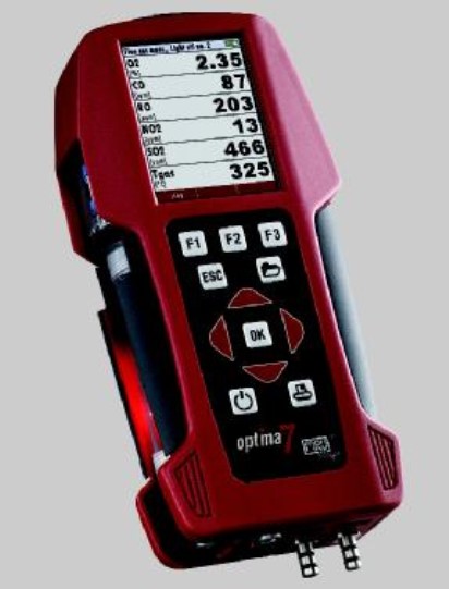
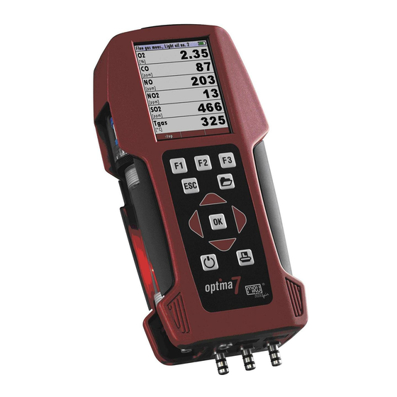
Общий вид газоанализатора Optima 7 представлен на рисунке 1.
Пломбирование газоанализатора Optima 7 не предусмотрено.
Лист № 2
Всего листов 7
Рисунок 1 – Общий вид газоанализатора Optima 7.
Программное обеспечение
Для идентификации ПО используется файловый менеджер Total Commander.
Обработка метрологических данных происходит на основе жестко определенного алго-
ритма без возможности изменения.
Метрологически незначимая часть, состоит из ПО, которое используется для обеспече-
ния наилучшей наглядности отображения информации.
Защита ПО осуществляется посредством записи защитного бита при программировании
микропроцессора в процессе производства газоанализаторов. Защитный бит запрещает чтение
кода микропрограммы, поэтому модификация программного обеспечения (умышленная или
неумышленная) невозможна. Снять защитный бит можно только при полной очистке памяти
микропроцессора вместе с программой находящейся в его памяти.
Уровень защиты программного обеспечения «высокий» в соответствии с Р 50.2.077-2014.
Программное обеспечение не влияет на метрологические характеристики.
Таблица 1 — Идентификационные данные программного обеспечения
Значение
Идентификационные данные (признаки)Аппаратное ПОПО для перепрограмми-
рования анализатора
Идентификационное наименование ПОOPT7.mastersoftOPT7.servicesoft
Номер версии (идентификационный номер) ПО ПО 1.10.10 V1.11.03
Цифровой идентификатор ПО 1156211 0202А41
Алгоритм вычисления цифрового идентифика-
тора ПОCRC32
Лист № 3
Всего листов 7
Метрологические и технические характеристики
Таблица 2 — Диапазон измерений и пределы допускаемой основной погрешности
Диапазон измеренийПределы допускаемой погрешности*
объемной доли абсолютной, об. доляотносительной, %
Канал О
2
от 0 до 21,0 %
0,2 %
–
Канал CO низкий
от 0 до 100 млн
-1
5 млн
-1
св. 100 до 300 млн
-1
включ.
5
Канал CO
от 0 до 400 млн
-1
20 млн
-1
св. 400 до 4000 млн
-1
включ.
5
св. 4000 до 10000 млн
-1
включ
10
Канал CO при установленном канале CO низкий
св. 300 до 400 млн
-1
включ.
20 млн
-1
св. 400 до 4000 млн
-1
включ.
5
св. 4000 до 10000 млн
-1
включ.
10
Канал CO высокий
от 0 до 800 млн
-1
40 млн
-1
св. 800 до 20000 млн
-1
включ.
5
Канал CO очень высокий
от 0 до 0,4 %
0,02 %
св. 0,4 до 10 % включ.
10
Канал NO низкий
от 0 до 50 млн
-1
5 млн
-1
св. 50 до 300 млн
-1
включ.
10
Канал NO
от 0 до 100) млн
-1
10 млн
-1
св.100 до 4000 млн
-1
включ.
10
Канал NO при установленном канале NO низкий
св. 300 до 4000 млн
-1
включ.
10
Канал NO
2
(до 500 млн
-1
)
от 0 до 50 млн
-1
5 млн
-1
св. 50 до 500 млн
-1
включ.
10
Канал SO
2
0 до 100 млн
-1
10 млн
-1
св. 100 до 4000 млн
-1
включ.
10
Канал H
2
S (до 300 млн
-1
)
от 0 до 100 млн
-1
10 млн
-1
св. 100 до 300 млн
-1
включ.
10
Канал СО
2
инфракрасный
от 0 до 5 %±0,2 %–
Канал СО
2
инфракрасный
от 0 до 8 %±0,2 %–
Канал СО
2
инфракрасный
от 0 до 10 %±0,5 %
св. 10 до 20 % включ.
5
Лист № 4
Всего листов 7
Продолжение таблицы 2
Диапазон измерений
объемной доли
Пределы допускаемой погрешности*
абсолютной, об. доляотносительной, %
Канал СО
2
инфракрасный
от 0 до 10 %
±0,5 %
св. 10 до 30 % включ.
5
Канал СО
2
инфракрасный
от 0 до 10 %±0,5 %
св. 10 до 50 % включ.
5
Канал CO инфракрасный
от 0 до 1,0 %
0,05 %
св. 1,0 до 30 % включ.
5
Канал СН
4
инфракрасный
от 0 до 0,4 %
0,02 %
св. 0,4 до 20 % включ.
5
Примечание:
*при температуре окружающей среды (20
5) °С.
абсолютнойотносительной,
Таблица 3 — Диапазон измерений температуры и пределы допускаемой основной погрешности
каналов измерения температуры
Диапазон измерений температуры
Пределы допускаемой погрешности*
%
зонд из нержавеющей стали (термоэлектрический преобразователь с НСХ типа «К» для
измерения температуры газа, диапазон измерений: от 0 до 650°С)
от 0 до 200
2
свыше 200 до 650
1
зонд из сплава INCONEL (термоэлектрический преобразователь с НСХ типа «К» для
измерения температуры газа, диапазон измерений: от 0 до 1000°С)
от 0 до 200
2
свыше 200 до 1000
1
зонд из пластика с открытым ЧЭ (термоэлектрический преобразователь с НСХ типа «К» для
измерений температуры воздуха, диапазон измерений: от 0 до 100°С)
от 0 до 100
о
С
1
Примечание:
*при температуре окружающей среды (20
5) °С.
абсолютнойотносительной, %
Таблица 4 — Диапазон измерений и пределы допускаемой основной погрешности каналов изме-
рения давления
Диапазон измеренийПределы допускаемой погрешности*
дифференциального давления, избыточного дав-
ления, вакуумметрического давления
от минус 2 гПа до 2 гПа
±0,02 гПа
от минус 100 гПа до минус 2 гПа
1
от 2 гПа до 100 гПа
1
Примечание:
*при температуре окружающей среды (20
5) °С.
Лист № 5
Всего листов 7
Таблица 5 — Пределы допускаемой дополнительной погрешности от изменения температуры
окружающей среды в диапазоне (5…40) °С в долях основной погрешности на каждые 10 °С
Канал измеренияЗначение
Канал О
2
(21 %)
0,3
Канал CO
0,2
Канал NO
0,3
Канал NO
2
0,3
Канал SO
2
0,5
Канал H
2
S
0,5
Канал СО
2
0,3
Канал СН
4
инфракрасный
0,5
Канал измерения температуры газа (воздуха)
0,1
Значение
Таблица 6 — Основные технические характеристики
Наименование характеристики
Параметры электрического питания:
— напряжение переменного тока
встроенный аккумулятор,
от внешнего источника 220 В
или от USB порта компьютера
7 (18)
от -20 до +50
244 (292)
113 (150)
54 (68)
0,9
1,2
2,7
Потребляемая мощность (с термобоксом), Вт, не более
Температура хранения, °С
Габаритные размеры (с термобоксом), мм, не более:
— длина
— ширина
— высота
Масса газоанализатора, кг, не более
Масса газоанализатора с термочехлом, кг, не более
Масса газоанализатора c термобоксом с обогревом, кг,
не более
Условия эксплуатации:
— температура окружающей среды, °С:
— относительная влажность воздуха, %
Класс защиты
Наработка на отказ, ч, не менее
от +5 до +45
от -15 до +40 (с термочехлом)
от -30 до +40 (с термобоксом с обог-
ревом)
до 95, без образования конденсата
IP 20 (с термобоксом IP 21)
8000
Знак утверждения типа
наносится на шильдик с индивидуальным номером прибора и может дублироваться на лицевой
панели прибора, а также, на титульный лист Руководства по эксплуатации газоанализатора
типографским способом.
Лист № 6
Всего листов 7
Комплектность средства измерений
Обозначение
Количество
Таблица 7 — Комплектность средства измерения
Наименование характеристики
Газоанализатор** с измерительными сенсорами
O
2
, СО, NO, NO
2
, SO
2
, H
2
S, СO
2
, СН
4
Внешние зонды и соединительные шнуры
Optima 7
—
МП 48157-11
по заказу
по заказу
1 шт.
1 экз.
1 экз.
Футляр для хранения и транспортировки
Руководство по эксплуатации
Методика поверки
Примечание.
** — в зависимости от заказанной комплектации.
Поверка
осуществляется по документу МП 48157-11 «Инструкция. Газоанализаторы «Optima 7″. Мето-
дика поверки», утвержденному ГЦИ СИ ФГУП «ВНИИМС» 15 сентября 2011 г.
Основные средства поверки:
— ГСО 10530-2014;
— ГСО 10531-2014;
— ГСО 10537-2014;
— ГСО 10546-2014;
— генератор газовых смесей ГГС модификация ГГС-03-03 (рег. № 62151-15).
Допускается применение аналогичных средств поверки, обеспечивающих определение
метрологических характеристик, поверяемых СИ с требуемой точностью.
Знак поверки наносится на свидетельство о поверке.
Сведения о методиках (методах) измерений
приведены в эксплуатационном документе.
Нормативные документы, устанавливающие требования к газоанализаторам Optima 7
ГОСТ 8.558-2009 ГСИ. Государственная поверочная схема для средств измерений тем-
ператур»
ГОСТ 8.187-76 ГСИ. Государственный специальный эталон и общесоюзная поверочная
схема для средств измерений разности давлений до 4
104 Па
Приказ Росстандарта от 14.12.2018 г. № 2664 Государственная поверочная схема для
средств измерений содержания компонентов в газовых и газоконденсатных средах
Техническая документация фирмы-изготовителя «MRU GmbH», Германия
Изготовитель
Фирма «MRU GmbH», Германия
Адрес: Fuchshalde 8-74172 Neckarsulm-Obereisesheim
Телефон: +49 (0) 7132 — 99 62 0
Web-сайт:
E-mail:
Заявитель
Общество с ограниченной ответственностью «МРУ Рус» (ООО «МРУ Рус»)
ИНН 771983350
Адрес: 107023, г. Москва, Семеновский пер. д.15, пом. I, эт. 4, ком.7
Телефон/факс: (499) 271-60-88
Web-сайт:
E-mail:
Лист № 7
Всего листов 7
Испытательный центр
Федеральноегосударственноеунитарноепредприятие«Всероссийскийнаучно-
исследовательский институт метрологической службы»
Адрес: 119361, г. Москва, ул. Озерная, д. 46
Тел./факс: (495) 437-55-77 / 437-56-66
Web-сайт: vniims.ru
E-mail:
Аттестат аккредитации ФГУП «ВНИИМС» по проведению испытаний средств измере-
ний в целях утверждения типа № 30004-13 от 26.07.2013 г.
Заместитель
Руководителя Федерального
агентства по техническому
регулированию и метрологииА.В. Кулешов
М.п.« ___ » _______________ 2020 г.
Готовы поверить данное средство измерений.
Поверка средств измерений.
| ГРСИ | Наименование СИ | Тип СИ | Производитель | МПИ | Ссылка |
| 6824-78 | Газоанализаторы | ГИАМ-1 | Нет данных | Поверка при выпуске. МПИ устанавливается местными органами (ГОСТ 8.002-71) | Перейти |
| 6823-78 | Газоанализаторы | Поток | П/я Р-6900, г.Москва | Поверка при выпуске. МПИ устанавливается местными органами (ГОСТ 8.002-71) | Перейти |
| 24713-03 | Газоанализаторы | ПЭМ-4М | ЗАО «Проманалитприбор», г.Новосибирск | 1 год | Перейти |
| 66741-17 | Газоанализаторы | ИДК-10 | ООО НПП «Томская электронная компания», г.Томск | 1 год; 2 года — для газоанализаторов с оптическим сенсором (ИК) | Перейти |
| 54054-13 | Газоанализаторы | ЕН3000М | ЗАО «ЭНАЛ», г.Москва | 1 год | Перейти |
Общество с ограниченной ответственностью
«Специализированное управление программ регионального развития»
ООО «СУПРР»
ИНН 7813337035 КПП 781301001 ОГРН 1057813279919
197198, Санкт-Петербург, ул. Шамшева, д. 8, лит. А, пом. 230
8(812)209-15-19
info@saprd.ru
![]()
Поверка средств измерений
ООО «СУПРР»
ИНН 7813337035 КПП 781301001
ОГРН 1057813279919
197198, Санкт-Петербург, ул. Шамшева, д. 8, лит. А, пом. 230
8(812)209-15-19
info@saprd.ru
![]()
Поверка средств измерений
Назначение
Описание
Программное обеспечение
Технические характеристики
Знак утверждения типа
Комплектность
Поверка
Сведения о методах измерений
Нормативные документы
Назначение
Газоанализаторы Optima 7 (далее — газоанализаторы) предназначены для измерения объемной доли O2, СО, NO, NO2, SO2, H2S, СО2, СН4, а также, параметров газовых сред в газоходах при контроле производственных процессов: температуры, давления.
Описание
Принцип действия газоанализаторов основан на непрерывном и селективном измерении электрохимическими (для газов O2, СО, NO, NO2, SO2, H2S) и инфракрасными (для газов СО, СО2, СН4) сенсорами анализируемых компонентов в потоке проходящего газа. Пробы газа для анализа отбирают при помощи зонда и встроенного в анализатор мембранного насоса. Анализируемый газ проходит по шлангу через сборник конденсата и фильтр в измерительный сенсор. Общее число установленных сенсоров для измерения газов может быть от одного до семи. Если в анализаторе присутствует более одного канала измерений СО или NO, с разными диапазонами измерений, переключение с меньшего на больший диапазон, происходит автоматически.
Газоанализаторы полностью автоматизированы. Встроенный микропроцессор управляет процессом измерений. Перед каждым измерением проводится автоматическая диагностика газоанализаторов, продувка сенсоров воздухом и установка нулевых показаний . Возможно автоматическое переключение сенсоров при превышении заданного диапазона массовых концентраций оксида углерода и оксида азота. Предусмотрено также автоматическое отключение приборов, если температура окружающей среды не соответствует заданной.
Газоанализаторы имеют 2 канала измерений температуры с термоэлектрическими преобразователями с номинальной статической характеристикой преобразования (НСХ) типа «К» по МЭК 60584-1 (ГОСТ Р 8.585-2001), принцип действия которых основан на термоэлектрическом эффекте — генерировании термоэлектродвижущей силы, возникающей из-за разности температур между соединениями различных металлов или сплавов, образующих часть одной и той же цепи. Газоанализаторы позволяют измерять избыточное и абсолютное давление (разрежение), а также разность давлений газа в неагрессивных средах. Для этого газоанализаторы снабжены тензоре-зистивными первичными сенсорами и электронной схемой.
При появлении на входах давления (разности давлений) происходит его преобразование в электрический сигнал. Значение этого сигнала пропорционально измеряемому давлению.
Газоанализаторы имеют крупный цветной графический дисплей с функцией «zoom», что позволяет индицировать на одной странице 6 параметров в обычном размере или два параметра в крупном размере. Последовательность и размер индикации на «страницах» дисплея, а также количество «страниц» индикации настраивается Пользователем.
Программное обеспечение (ПО) позволяет на основании измеренных значений состава и температуры анализируемого газа, рассчитать эффективность и потери при сжигании топлива, содержание диоксида углерода (при отсутствии соответствующего сенсора), температуру точки росы, коэффициент избытка воздуха X. Полученные результаты выводятся на дисплей, и внешний принтер.
Общий вид газоанализатора Optima 7 представлен на рисунке 1.
Пломбирование газоанализатора Optima 7 не предусмотрено.

Рисунок 1 — Общий вид газоанализатора Optima 7.
Программное обеспечение
Для идентификации ПО используется файловый менеджер Total Commander.
Обработка метрологических данных происходит на основе жестко определенного алгоритма без возможности изменения.
Метрологически незначимая часть, состоит из ПО, которое используется для обеспечения наилучшей наглядности отображения информации.
Защита ПО осуществляется посредством записи защитного бита при программировании микропроцессора в процессе производства газоанализаторов. Защитный бит запрещает чтение кода микропрограммы, поэтому модификация программного обеспечения (умышленная или неумышленная) невозможна. Снять защитный бит можно только при полной очистке памяти микропроцессора вместе с программой находящейся в его памяти.
Уровень защиты программного обеспечения «высокий» в соответствии с Р 50.2.077-2014.
Программное обеспечение не влияет на метрологические характеристики.
Таблица 1 — Идентификационные данные программного обеспечения
|
Идентификационные данные (признаки) |
Значение |
|
|
Аппаратное ПО |
ПО для перепрограммирования анализатора |
|
|
Идентификационное наименование ПО |
OPT7.mastersoft |
OPT7.servicesoft |
|
Номер версии (идентификационный номер) ПО |
ПО 1.10.10 |
V1.11.03 |
|
Цифровой идентификатор ПО |
1156211 |
0202А41 |
|
Алгоритм вычисления цифрового идентификатора ПО |
CRC32 |
Технические характеристики
Таблица 2 — Диапазон измерений и пределы допускаемой основной погрешности
|
Диапазон измерений объемной доли |
Пределы допускаемой погрешности* |
|
|
абсолютной, об. доля |
относительной, % |
|
|
Канал О2 |
||
|
от 0 до 21,0 % |
±0,2 % |
_ |
|
Канал CO низкий |
||
|
от 0 до 100 млн-1 св. 100 до 300 млн-1 включ. |
±5 млн-1 |
±5 |
|
Канал CO |
||
|
от 0 до 400 млн-1 св. 400 до 4000 млн-1 включ. св. 4000 до 10000 млн-1 включ |
±20 млн-1 |
±5 ±10 |
|
Канал CO при установленном канале CO низкий |
||
|
св. 300 до 400 млн-1 включ. св. 400 до 4000 млн-1 включ. св. 4000 до 10000 млн-1 включ. |
±20 млн-1 |
±5 ±10 |
|
Канал CO высокий |
||
|
от 0 до 800 млн-1 св. 800 до 20000 млн-1 включ. |
±40 млн-1 |
±5 |
|
Канал CO очень высокий |
||
|
от 0 до 0,4 % св. 0,4 до 10 % включ. |
±0,02 % |
±10 |
|
Канал NO низкий |
||
|
от 0 до 50 млн-1 св. 50 до 300 млн-1 включ. |
±5 млн-1 |
±10 |
|
Канал NO |
||
|
от 0 до 100) млн-1 св.100 до 4000 млн-1 включ. |
±10 млн-1 |
±10 |
|
Канал NO при установленном канале NO низкий |
||
|
св. 300 до 4000 млн-1 включ. |
±10 |
|
|
Канал |
NO2 (до 500 млн-1) |
|
|
от 0 до 50 млн-1 св. 50 до 500 млн-1 включ. |
±5 млн-1 |
±10 |
|
Канал SO2 |
||
|
0 до 100 млн-1 св. 100 до 4000 млн-1 включ. |
±10 млн-1 |
±10 |
|
Канал H2S (до 300 млн-1) |
||
|
от 0 до 100 млн-1 св. 100 до 300 млн-1 включ. |
±10 млн-1 |
±10 |
|
Канал СО2 инфракрасный |
||
|
от 0 до 5 % |
±0,2 % |
_ |
|
Канал СО2 инфракрасный |
||
|
от 0 до 8 % |
±0,2 % |
_ |
|
Канал СО2 инфракрасный |
||
|
от 0 до 10 % св. 10 до 20 % включ. |
±0,5 % |
±5 |
Продолжение таблицы 2
|
Диапазон измерений объемной доли |
Пределы допускаемой погрешности* |
|
|
абсолютной, об. доля |
относительной, % |
|
|
Канал СО2 инфракрасный |
||
|
от 0 до 10 % св. 10 до 30 % включ. |
±0,5 % |
±5 |
|
Канал СО2 инфракрасный |
||
|
от 0 до 10 % св. 10 до 50 % включ. |
±0,5 % |
±5 |
|
Канал CO инфракрасный |
||
|
от 0 до 1,0 % св. 1,0 до 30 % включ. |
±0,05 % |
±5 |
|
Канал СН4 инфракрасный |
||
|
от 0 до 0,4 % св. 0,4 до 20 % включ. |
±0,02 % |
±5 |
|
Примечание: *при температуре окружающей среды (20 ± 5) °С. |
Таблица 3 — Диапазон измерений температуры и пределы допускаемой основной погрешности каналов измерения температуры
|
Диапазон измерений температуры |
Пределы допускаемой погрешности* |
|
|
абсолютной |
относительной,% |
|
|
зонд из нержавеющей стали (термоэлектрический преобразователь с НСХ типа «К» для измерения температуры газа, диапазон измерений: от 0 до 650°С) |
||
|
от 0 до 200 свыше 200 до 650 |
±2 |
±1 |
|
зонд из сплава INCONEL (термоэлектрический преобразователь с НСХ типа «К» для измерения температуры газа, диапазон измерений: от 0 до 1000°С) |
||
|
от 0 до 200 свыше 200 до 1000 |
±2 |
±1 |
|
зонд из пластика с открытым ЧЭ (термоэлектрический преобразователь с НСХ типа «К» для измерений температуры воздуха, диапазон измерений: от 0 до 100°С) |
||
|
от 0 до 100 оС |
±1 |
|
|
Примечание: *при температуре окружающей среды (20 ± 5) °С. |
Таблица 4 — Диапазон измерений и пределы допускаемой основной погрешности каналов измерения давления
|
Диапазон измерений дифференциального давления, избыточного давления, вакуумметрического давления |
Пределы допускаемой погрешности* |
|
|
абсолютной |
относительной,% |
|
|
от минус 2 гПа до 2 гПа от минус 100 гПа до минус 2 гПа от 2 гПа до 100 гПа |
±0,02 гПа |
±1 ±1 |
|
Примечание: *при температуре окружающей среды (20 ± 5) °С. |
Таблица 5 — Пределы допускаемой дополнительной погрешности от изменения температуры окружающей среды в диапазоне (5.. .40) °С в долях основной погрешности на каждые 10 °С
|
Канал измерения |
Значение |
|
Канал О2 (21 %) |
±0,3 |
|
Канал CO |
±0,2 |
|
Канал NO |
±0,3 |
|
Канал NO2 |
±0,3 |
|
Канал SO2 |
±0,5 |
|
Канал H2S |
±0,5 |
|
Канал СО2 |
±0,3 |
|
Канал СН4 инфракрасный |
±0,5 |
|
Канал измерения температуры газа (воздуха) |
±0,1 |
Таблица 6 — Основные технические характеристики
|
Наименование характеристики |
Значение |
|
Параметры электрического питания: — напряжение переменного тока |
встроенный аккумулятор, от внешнего источника 220 В или от USB порта компьютера |
|
Потребляемая мощность (с термобоксом), Вт, не более |
7 (18) |
|
Температура хранения, °С |
от -20 до +50 |
|
Габаритные размеры (с термобоксом), мм, не более: |
|
|
— длина — ширина — высота |
244 (292) 113 (150) 54 (68) |
|
Масса газоанализатора, кг, не более Масса газоанализатора с термочехлом, кг, не более Масса газоанализатора c термобоксом с обогревом, кг, не более |
0,9 1,2 2,7 |
|
Условия эксплуатации: |
|
|
— температура окружающей среды, °С: |
от +5 до +45 от -15 до +40 (с термочехлом) от -30 до +40 (с термобоксом с обогревом) |
|
— относительная влажность воздуха, % |
до 95, без образования конденсата |
|
Класс защиты |
IP 20 (с термобоксом IP 21) |
|
Наработка на отказ, ч, не менее |
8000 |
Знак утверждения типа
наносится на шильдик с индивидуальным номером прибора и может дублироваться на лицевой панели прибора, а также, на титульный лист Руководства по эксплуатации газоанализатора типографским способом.
Комплектность
Таблица 7 — Комплектность средства измерения
|
Наименование характеристики |
Обозначение |
Количество |
|
Газоанализатор** с измерительными сенсорами O2, СО, NO, NO2, SO2, H2S, СО2, СН4 |
Optima 7 |
по заказу |
|
Внешние зонды и соединительные шнуры |
— |
по заказу |
|
Футляр для хранения и транспортировки |
— |
1 шт. |
|
Руководство по эксплуатации |
— |
1 экз. |
|
Методика поверки |
МП 48157-11 |
1 экз. |
|
Примечание. ** — в зависимости от заказанной комплектации. |
Поверка
осуществляется по документу МП 48157-11 «Инструкция. Газоанализаторы «Optima 7″. Методика поверки», утвержденному ГЦИ СИ ФГУП «ВНИИМС» 15 сентября 2011 г.
Основные средства поверки:
— ГСО 10530-2014;
— ГСО 10531-2014;
— ГСО 10537-2014;
— ГСО 10546-2014;
— генератор газовых смесей ГГС модификация ГГС-03-03 (рег. № 62151-15).
Допускается применение аналогичных средств поверки, обеспечивающих определение метрологических характеристик, поверяемых СИ с требуемой точностью.
Знак поверки наносится на свидетельство о поверке.
Сведения о методах измерений
приведены в эксплуатационном документе.
Нормативные документы
ГОСТ 8.558-2009 ГСИ. Государственная поверочная схема для средств измерений температур»
ГОСТ 8.187-76 ГСИ. Государственный специальный эталон и общесоюзная поверочная
схема для средств измерений разности давлений до 4-104 Па
Приказ Росстандарта от 14.12.2018 г. № 2664 Государственная поверочная схема для средств измерений содержания компонентов в газовых и газоконденсатных средах
Техническая документация фирмы-изготовителя «MRU GmbH», Германия
- Manuals
- Brands
- mru Manuals
- Measuring Instruments
- OPTIMA7 biogas
- User manual
-
Contents
-
Table of Contents
-
Troubleshooting
-
Bookmarks
Quick Links
OPTIMA7 biogas
USER MANUAL
4102EN-BIO
Related Manuals for mru OPTIMA7 biogas
Summary of Contents for mru OPTIMA7 biogas
-
Page 1
OPTIMA7 biogas USER MANUAL 4102EN-BIO… -
Page 2
USER MANUAL OPTIMA7 Biogas Producer: Legal notices / Intellectual property rights comments Original user manual © 2021 by MRU No part of this manual my be published in any form (print, fotocopy, electronic media or any other publication form) without a written approval by the publisher. -
Page 3: Table Of Contents
Configuration of the measurement window (display content) – only Flue gas measurement ………………27 Configuring zoom window …………….28 6 Preparing measurement ……….29 6.1. Ensure power supply …………….. 29 6.2. Automatic Auto-off function …………..29 3 / 78 MRU GmbH, D-74172 Neckarsulm…
-
Page 4
USER MANUAL OPTIMA7 Biogas 6.3. Measuring with grid power supply / Battery charging ….29 6.4. Battery charge condition …………….. 29 6.5. Operating temperature …………….30 6.6. Controlling Condensate separator (water trap) ……. 30 6.7. Connections and tightness …………..31 6.8. -
Page 5
Performing and checking the update …………72 In case of error ………………..73 11.6. Troubleshooting ………………75 Troubleshooting the analyser ……………. 75 Troubleshooting condensate separator …………. 76 12 Declaration of conformity ……….77 5 / 78 MRU GmbH, D-74172 Neckarsulm… -
Page 6: Information For Product And Safety
USER MANUAL OPTIMA7 Biogas Information for product and safety 1.1. Safety manual All general information and safety precautions of MRU products are listed in the supplied separate safety manual. Therefore, this manual must be read and observed before the first use of the instrument .
-
Page 7: Ensure Safety
S 2 years and NO — 3 years. The use of the analyser for regulatory purposes is subject to special reg- ulations (for example a periodical examination of the analyser). Please obtain the appropriate regulations from your local responsible authority. 7 / 78 MRU GmbH, D-74172 Neckarsulm…
-
Page 8
This area classification is country specific, please observe and notice it. • MRU instruments may be operated in hazardous areas zone 2 by skilled users obeying local guidelines e.g. by using LEL gas detectors… -
Page 9: User Guidelines For Rechargeable Batteries
• Do not cut or squeeze the connecting cables of the rechargeable bat- tery. • Do not connect the (+) contact to the (-) contact or metal. • Non-observance of the above guidelines can cause heat, fire and ex- plosions 9 / 78 MRU GmbH, D-74172 Neckarsulm…
-
Page 10: Introduction
USER MANUAL OPTIMA7 Biogas 2 Introduction • This manual enables you to understand and safely operate this MRU Analyzer. • Please read this manual with great vigilant and get familiar with the product before using it. • This analyser may only be operated by competent personnel and for its intended use.
-
Page 11
The analyser must be used according to instructions for the intended use. Our analyzers are checked according to the following regulations: VDE 0411 (EN61010) and DIN VDE 0701 before they leave the MRU GmbH factory. MRU technical products are designed and manufactured according to DIN 31000/ VDE 1000 and UVV = VBG 4 of the professional guilds for fine mechanics and electrical engineering. -
Page 12: About Us
USER MANUAL OPTIMA7 Biogas 2.2. About us The analyser is produced by the MRU GmbH in Neckarsulm, Germany (Founded in 1984), a medium sized company that specializes in devel- oping, producing and marketing high quality emission monitoring analysers. MRU GmbH produces a wide range of instruments, from standard analysers up to tailor made industrial analysers.
-
Page 13: Packaging
Hazardous waste must be returned to MRU prepaid. 2.5. Return of electronic equipment MRU GmbH is required to accept the return, for proper disposal, of all analysers delivered after 13th of August 2005. Analysers must be returned to MRU prepaid.
-
Page 14: Description
USER MANUAL OPTIMA7 Biogas 3 Description 3.1. Gas flow diagram The analyser extracts a partial volume of the biogas and analyses it for its components using NDIR and electrochemical sensors. Position Description Biogas sampling hose Connection to gas outlet Condensate separator…
-
Page 15: Analyzer
Temperature connector T2 Temperature connector T1 Pressure connector P1 Pressure connector P2 Gas outlet IR-Interface USB-port and charging port SD-card reader Fixing magnets Analyzer feet Handle strip Gas outlet Pressure connector P3 Connector AUX 15 / 78 MRU GmbH, D-74172 Neckarsulm…
-
Page 16: Condensate Separator
USER MANUAL OPTIMA7 Biogas NOTE If during zeroing T air (5) is disconnected, then value of T gas at the end of zeroing will be used. In this case, the measuring value will be displayed green coloured. If T air (5) will be connected during the measurement,…
-
Page 17: Probes
3.4. Probes The Analyzer is available with different probes, both with exchangeable probe tubes. A complete list of available probes can be found in the current price list of this analyser. 17 / 78 MRU GmbH, D-74172 Neckarsulm…
-
Page 18: Operating
USER MANUAL OPTIMA7 Biogas 4 Operating 4.1. Display All information required to operate the analyser is displayed as shown below. Position Description Menu bar Function key bar Display panel 1. Menu 2. Measurement value Zeroing active SD-Card in the slot 1.
-
Page 19: Keypad
Abort or return to the menu above Arrow Keys Jump in between lines, change values Confirmation key, select a marked menu point Activates the printer function in the Printer measurement and service window 19 / 78 MRU GmbH, D-74172 Neckarsulm…
-
Page 20: Menu Structure
USER MANUAL OPTIMA7 Biogas 4.3. Menu structure The analyser organizes all available actions in three main menus: • Menu Measurement All available measurement options will be displayed and can be se- lected here. • Menu Storage All available storage options will be displayed and can be selected here.
-
Page 21: First Usage
If activated and if ON key is pressed (possibly tion inadvertently), then the message „3 seconds OK key press is displayed Keyboard beeper ON / OFF Keyboard beeper activated or deactivated Logo switch ON ON / OFF Logo will be displayed 21 / 78 MRU GmbH, D-74172 Neckarsulm…
-
Page 22: Setting Measurement
USER MANUAL OPTIMA7 Biogas 5.3. Setting measurement ► Press F3. The Extras menu appears. ► Press F3. The menu Settings appears. ► Press F3. The menu Measurement settings appears. In the «Measurement settings» menu you can make for example the fol-…
-
Page 23: Setting Printer Type And Print Out
The menu print-out appears. In the menu «print-out» menu you can make for example the following adjustments: Printer type Select printer type MRU / HP Print logo ON/OFF Print logo Print option SHORT: Print-out without area for signature and site in-…
-
Page 24: Setting Bluetooth Parameters
USER MANUAL OPTIMA7 Biogas 5.6. Setting Bluetooth parameters Depending on the equipment, the analyser can be used to exchange measurement data with external devices via Bluetooth: • With MRU4u (App for Android and iOs smartphones) • With MRU4Win • With MRU Bluetooth printer •…
-
Page 25: Setting Date And Time
The following settings are possible: • Measurement windows: configuration of what and where will be dis- played in the 3 measurement value windows. • Zoom – window: select what will be displayed in the zoom — window 25 / 78 MRU GmbH, D-74172 Neckarsulm…
-
Page 26: Setting Co Limit Value (Only Gas Flue Measurement)
USER MANUAL OPTIMA7 Biogas Setting CO limit value (only gas flue measurement) ► Select Gas measurements. ► Press OK. The menu Selection meas. program appears. ► Select the desired measuring program from which the CO limit value is to be set ►…
-
Page 27: Configuration Of The Measurement Window (Display Content) — Only Flue Gas Measurement
Now you select “Save measuring window”. All your changes will be saved and all saved values will be printed when using the printer func- tion. Start the measuring program – once you are inside the measuring win- dow press the menu key 27 / 78 MRU GmbH, D-74172 Neckarsulm…
-
Page 28: Configuring Zoom Window
USER MANUAL OPTIMA7 Biogas Configuring zoom window Three zoom windows are available in each measuring program for the zoomed display of 2 measured values each. Which values are displayed in a zoomed view can be configured? ► Start a measuring program.
-
Page 29: Preparing Measurement
USER MANUAL OPTIMA 7 Biogas 6 Preparing measurement 6.1. Ensure power supply The analyser can be used with: • with the internal MRU battery (provided) • with the MRU battery charger (provided) External equipment may only be connected while the analyser is switched off! 6.2.
-
Page 30: Operating Temperature
USER MANUAL OPTIMA7 Biogas 6.5. Operating temperature If the analyser has been stored at low temperatures, it will require some time to equilibrate to the ambient temperature before being switched on. If it does not equilibrate, condensation will occur inside the analyser! If the temperature is out of its operation range you will see the follow- ing messages on the display: “Analyzer too hot”…
-
Page 31: Connections And Tightness
During zeroing, the -> 0.0 <- symbol flashes in the upper right corner of the display. After zeroing is complete, the analyser is ready for measurement. If sensors are faulty, the error is identified during zeroing and an error message is displayed. 31 / 78 MRU GmbH, D-74172 Neckarsulm…
-
Page 32: Repeating The Zeroing
USER MANUAL OPTIMA7 Biogas 6.9. Repeating the zeroing The zeroing can be repeated at any time as long as the probe is not in- side the stack. 32 / 78 MRU GmbH, D-74172 Neckarsulm…
-
Page 33: Performing Measurement
► The exhaust outlet at the rear of the analyser may never be covered during a measurement, never oper- ate the analyser in a transport case. ► Go to the Measurement menu. ► Select the desired measurement program. ► Press OK. 33 / 78 MRU GmbH, D-74172 Neckarsulm…
-
Page 34: Performing Biogas Measurement
USER MANUAL OPTIMA7 Biogas 7.2. Performing Biogas measurement Measurement start / stop Menu key Store measurement Print display content Back to Measurement menu 7.3. Flue gas measurement (option) Measurement values can be organized on three pages, each page dis- playing 6 measurement values.
-
Page 35: Setting Co-Limit Value (Only With Flue Gas Measurement)
If in the function key bar «store» is indicated, you can store with the accompanying function key F2 or F3 the measurement in the data memory. The function of the data memory is explained in chapter 8Data Storage, Page 44. 35 / 78 MRU GmbH, D-74172 Neckarsulm…
-
Page 36: Printing Measurement Values
USER MANUAL OPTIMA7 Biogas 7.6. Printing measurement values The measurement results can be printed out on the Speedprinter (IR ta- ble printer, art. no. 62693) with the printer key. ► You must align the Speedprinter as follows: All values that can be seen in the measurement window on all three pages will be printed, double measurement values will only be printed once.
-
Page 37: Terminate Measurement
► Go to the Measurement menu. ► Select Last measured values. The measured value window with the last measured values ap- pears. ► Press F1. The measurement is continued. 37 / 78 MRU GmbH, D-74172 Neckarsulm…
-
Page 38: Pressure Measurement (Option)
USER MANUAL OPTIMA7 Biogas 7.9. Pressure measurement (option) Pressure (4 values) is measured and saved to the selected measurement name. The actual measured value is displayed in the middle of the dis- play. The 4 measurement names can be changed as desired.
-
Page 39: Differential Temperature Measurement (Option)
The menu Diff. Temp. Measurement appears. The temperatures T1, T2 and the difference are displayed. NOTE The accuracy of the difference temperature measure- ment is guaranteed only on use of the MRU temperature sensors. 39 / 78 MRU GmbH, D-74172 Neckarsulm…
-
Page 40: Gas Flow Measurement (Option)
USER MANUAL OPTIMA7 Biogas 7.11. Gas flow measurement (option) This option allows the user to determine the gas velocity at a single point by means of a pitot tube (order separately). Based on the differential pressure between the ports of the Pitot tube and the absolute pressure, the gas velocity is calculated.
-
Page 41
] + 18*[H O] + 16*[CH ] + 28*[N [O2]: oxygen in [%] [CO2]: carbon dioxide in [%] [CH4]: methane in [%] [H2O]: water in [%] [N2]: nitrogen in [%] Unit of molar mass: 41 / 78 MRU GmbH, D-74172 Neckarsulm… -
Page 42
USER MANUAL OPTIMA7 Biogas Gas density The gas density is calculated on the equation 2: Equation 2: gas density p: gas density P abs: indicated the absolute pressure in [Pa] M: molar mass R: gas constant, amounts T gas: gas temperature in Kelvin… -
Page 43
The current volume flow is, the current flow velocity multiplied by the cross-section area. Equation 5: volume flow v,mom : current volume flow in [m³/s] v,mom : current flow velocity in [m/s] A: cross-section area in [m²] 43 / 78 MRU GmbH, D-74172 Neckarsulm… -
Page 44: Data Storage
The analyser can store up to 4,000 different sites. New sites can be added in the analyser. Modifications can be done us- ing an external PC program e.g. MRU Win. NOTE New sites created in the analyser will NOT be transferred back to the computer program.
-
Page 45: Calling Up Information About Data Storage
• view all data of the stored sites • create new sites • change date of existing sites • delete sites NOTE New sites created in the analyser will NOT be transferred to a PC program 45 / 78 MRU GmbH, D-74172 Neckarsulm…
-
Page 46: Create New Site
USER MANUAL OPTIMA7 Biogas Create new site ► Go to the Storage menu. ► Press F2. The menu Sites administration appears. ► Press F1. The menu Modify site appears. ► Press F1 to assign manually a site number to the site.
-
Page 47: View Sites
► Press OK. The menu Search a site appears. You can choose to filter by Site number, by content in Line 2 or for the rest of the other text lines. 47 / 78 MRU GmbH, D-74172 Neckarsulm…
-
Page 48: Changing Sites
USER MANUAL OPTIMA7 Biogas ► Select a line in which you want to search for content. In this example, the search is performed in line 2. ► Press F3. A window appears. ► Enter the desired search term. In this example the search term is John Example.
-
Page 49: Deleting Sites
► Press OK. A message appears. ► Select continue to delete all sites. ► Select abort to retain all sites. ► Press OK. Depending on the selection, the site is deleted or retained 49 / 78 MRU GmbH, D-74172 Neckarsulm…
-
Page 50: Data Transfer Using Sd Card
USER MANUAL OPTIMA7 Biogas 8.4. Data transfer using SD card The data exchange format is CSV. A character-separated values (CSV) file is a simple text format for a database table. Each record in the table is one line of the text file. Each field value of a record is separated from the next by a character.
-
Page 51
However, the analyser marks the files that have been im- ported successfully. If you try to import a file with the same analyser that is already in the analyser you will get a red information screen. 51 / 78 MRU GmbH, D-74172 Neckarsulm… -
Page 52: Exporting Sites
USER MANUAL OPTIMA7 Biogas Exporting sites ► Go to the Storage menu. ► Select Sites onto SD card. ► Press OK The menu Sites onto SD card appears. ► Press F2. The sites are exported. This function can be used for an analyser back up or if you wish to sup- ply the analyser information to a computer program or another ana- lyser.
-
Page 53: Exporting Combustion Measurements
The created file has the file name “DDMxxxxx.csv“, in which the xxxxx are con- tinuing 5-digit numbers with leading zeros. The created file has a column header with the following information: Site num- ber, Date/Time, as well as 4 saved pressure measurements. 53 / 78 MRU GmbH, D-74172 Neckarsulm…
-
Page 54: Measurement In Data Storage
USER MANUAL OPTIMA7 Biogas 8.5. Measurement in Data storage Viewing measurements ► Go to the Storage menu. ► Select View measurements. ► Press OK. The menu View measurements appears. An overview of the number of stored measurements according to the measurement type appears.
-
Page 55: Deleting Measurements
A message appears. Select continue to delete all measurements. Select abort to retain all measurements. ► Press OK. Depending on the selection, the measurement data are deleted or retained. 55 / 78 MRU GmbH, D-74172 Neckarsulm…
-
Page 56: Transferring Measurements To Sd-Card (Option)
USER MANUAL OPTIMA7 Biogas Transferring measurements to SD-Card (Option) he analyser offers the possibility to export all stored measurements to a SD card. ► Go to the Storage menu ► Select Measurements to SD card. ► Press OK. ► Select the desired measurement type.
-
Page 57: Extras / Adjustments
If you enter a wrong pin code you will be exited into the “Extra Menu” again. Please contact MRU GmbH if you need the Pin Code for your analyser. Press the Enter key if you should have landed in this menu by accident and you will be exited into the “Extra Menu”…
-
Page 58: Default Settings
USER MANUAL OPTIMA7 Biogas 9.2. Default settings The analyser will be reset to original delivery settings. NOTE With the default setting, all individual settings are lost. ► Go to the Extras menu. ► Select Default settings. ► Press OK. A window appears.
-
Page 59: User Manual Optima 7 Biogas
In this menu you will see all service values of the sensors and also other parameters. In case of a defect contact the MRU service department. The MRU ser- vice technician will ask you about these values or he will ask you to send them by fax or email.
-
Page 60: Leak Proof Test
USER MANUAL OPTIMA7 Biogas 9.4. Leak proof test With the leak proof test, the system is checked by the device (incl. the condensate separator) on undensity. The internal gas pump generates in addition a subpressure which is measured over the built-in draft sen- sor and is observed for a period of 10 seconds.
-
Page 61: Contents Sd Card
If no undensity is ascertained in these external parts the OPTIMA 7 Combustion Analyzer has to be checked in a service department (worldwide service departments see www.mru.eu) 9.5. Contents SD card ► Go to the menu Extras.
-
Page 62: Contents Analyzer Information
USER MANUAL OPTIMA7 Biogas 9.6. Contents Analyzer information Here you will find information about the analyser and the installed op- tions. ► Go to the Extras menu. ► Select Device info. The menu Device info appears. ► Press F2.
-
Page 63: Maintenance And Care
The next time you switch on, you will be reminded to carry out the an- nual service. A complete service at an MRU service centre (MRU service centres can be found at www.mru.eu) includes the function check and calibration or…
-
Page 64: Appendix
USER MANUAL OPTIMA7 Biogas Appendix 11.1. Technical data General data English Values Operating temperature +5°C … +45 °C / 41 °F … 113 °F Rel. Humidity, non-condensing Storage Temperature -20°C … +50°C / -4°F … 122°F Internal Battery Pack, Li-Ion, 20h…
-
Page 65
Nom. Measuring Range 0 — 1000 ppm Overload Range ≤ 2000 ppm Resolution 1 ppm ± 5 ppm / Accuracy abs./reading 5% (0 .. 500 ppm) 10% (> 500 ppm) Response Time T90 < 40s 65 / 78 MRU GmbH, D-74172 Neckarsulm… -
Page 66
USER MANUAL OPTIMA7 Biogas Electrochemical Sensor on additional position (depending on configura- tion) Nom. Measuring Range 0 — 500 ppm Overload Range < 2000 ppm Resolution 1 ppm ± 5 ppm / Accuracy abs./reading 5% (0 .. 500 ppm) 10% (> 500 ppm) Response Time T90 <… -
Page 67
4 Pa … 100 hPa Measuring Range 1 m/s … 100 m/s ± 1m/s (0..2 m/s) Accuracy without error of ± 0,2 m/s (2… 10 m/s) pitot tube ± 0,5% (> 10 m/s) Accuracy 67 / 78 MRU GmbH, D-74172 Neckarsulm… -
Page 68: Analysis And Calculations
USER MANUAL OPTIMA7 Biogas Flow measurement Input cross section area Shape Circle / Rectangle/ Square / free Input Unit cm, m, cm , mm , feet , inch Range 0…60m Measuring Range 0,1l/s — 6000m Resolution 11.2. Analysis and calculations…
-
Page 69
The calculation of the the 2 gcv values is (with presumption, that CH4 is the significant combustable part of the gas mixture): gcv [MJ/m³] = 1.109 * ncv [MJ/m³] gcv [MJ/kg] = 1.109 * ncv [MJ/kg] 69 / 78 MRU GmbH, D-74172 Neckarsulm… -
Page 70
USER MANUAL OPTIMA7 Biogas Measured values Unit Temp. Ambient air (Thermo- [°C] couple) Temp. Flue gas (Thermocou- [°C] ple) [ppm] Pressure [hPa] Available conversions of CO [ppm] related to. on 0% rest (undiluted) [ppm] related to. on fuel type dependent O… -
Page 71: Text Input
Selected letter or number will over write the current letter or number Abort the window, changes will NOT be saved 11.4. Asking user for decision The analyser requires confirmation of the user decision for various func- tions 71 / 78 MRU GmbH, D-74172 Neckarsulm…
-
Page 72: Firmware Update
USER MANUAL OPTIMA7 Biogas Select a line Confirm the action Abort the window, changes will NOT be saved 11.5. Firmware update Install the new software version in the analyser ► Go to the Extras menu. ► Select Device info. The menu Device info appears.
-
Page 73: In Case Of Error
In case of an error, the red LED of the condensate separator flashes. The inserted SD card was not identified then. (Check that the SD card is correctly inserted and perform a reset by pressing the ESC and ON keys simultaneously). 73 / 78 MRU GmbH, D-74172 Neckarsulm…
-
Page 74
USER MANUAL OPTIMA7 Biogas Where can I get help if the update was not successful? Please contact your responsible sales representative or via email: info@mru.de 74 / 78 MRU GmbH, D-74172 Neckarsulm… -
Page 75: Troubleshooting
(loose connection), re- sate at the probe tip. move condensate from the probe tip. 75 / 78 MRU GmbH, D-74172 Neckarsulm…
-
Page 76: Troubleshooting Condensate Separator
USER MANUAL OPTIMA7 Biogas Troubleshooting condensate separator 1. Effect 2. Cause 3. Solution Dirt and / or humidity in- Fine filters are wet and / Check filters more side the device or dirty. often No filter effects Renew them if nec-…
-
Page 77: Declaration Of Conformity
USER MANUAL OPTIMA 7 Biogas Declaration of conformity 77 / 78 MRU GmbH, D-74172 Neckarsulm…
-
Page 78
USER MANUAL OPTIMA7 Biogas 78 / 78 MRU GmbH, D-74172 Neckarsulm…
Общая информация
Газоанализаторы Optima 7 (далее – газоанализаторы) предназначены для измерения объемной доли O , СО, NO, NO , SO , H S, СO , СН , а также, параметров газовых сред в газоходах 2 2 2 2 2 4 при контроле производственных процессов: температуры, давления.
Газоанализаторы Optima 7 внесены производителем Фирма «MRU GmbH», Германия в
Государственный реестр средств измерений (ГРСИ РФ) рег. №48157-11.
Информация о поверке
Поиск результатов поверки:
Найдено результатов поверки: 2444
Скачать
Информация из Госреестра
(ФГИС «АРШИН») #
| Основные атрибуты | |
|---|---|
| Номер в госреестре | 48157-11 |
| Наименование СИ | Газоанализаторы |
| Обозначение типа СИ | Optima 7 |
| Номер записи | Нет данных |
| Дата опубликования | Нет данных |
| Страна и предприятие-изготовитель | |
|---|---|
| Изготовитель | Фирма «MRU GmbH», Германия |
| Страна | ГЕРМАНИЯ |
| Отсутствует в списке лиц, направивших уведомление о начале осуществления предпринимательской деятельности | Да |
| Предприятие-изготовитель | Фирма «MRU GmbH» |
| Общее | |
|---|---|
| Процедура | Стандартная |
| Сведения о типе СИ | Срок свидетельства |
| Срок свидетельства | 18 августа 2026 г. |
| Межповерочный интервал | |
|---|---|
| МПИ | 1 год |
| Наличие периодической поверки | Да |
| Дополнительно | |
|---|---|
| Статус | Действует |
Газоанализаторы 1889
76637-19

Фирма «Super Systems Inc.», США
61055-15

69994-17

ООО НПФ «АНАТЭК», г. Москва
84489-22

Компания «Picarro, Inc.», США