-
Contents
-
Table of Contents
-
Troubleshooting
-
Bookmarks
Quick Links
GA-945GM-S2
Intel
Pentium
®
®
User’s Manual
Rev. 1001
12ME-945GMS2R-1001R
* The WEEE marking on the product indicates this product must not be disposed of with user’s other household waste
and must be handed over to a designated collection point for the recycling of waste electrical and electronic equipment!!
* The WEEE marking applies only in European Union’s member states.
4 LGA775 Processor Motherboard
Summary of Contents for Gigabyte GA-945GM-S2
(Ocr-Read Summary of Contents of some pages of the Gigabyte GA-945GM-S2 Document (Main Content), UPD: 01 March 2023)
-
36, GA-945GM-S2 Motherboard — 36 — English 2-3 Integrated Peripherals On-Chip Primary PCI IDE Enabled Enable onboard 1st channel IDE port. (Default value) Disabled Disable onboard 1st channel IDE port. On-Chip SATA Mode Disabled Disable this function. Auto BIOS will auto detect. (Default value) Combined Set On-Chip SATA mode to Combined, you can use up to 4 HDDs on the motherboard; 2 for SATA and the other for PATA. En…
-
69, Appendix- 69 — English Setting Up 8-Channel Audio STEP 3: Connect the 8-channel speakers to the audio jacks on the motherboard and the surround cable, a small window will pop up and ask you what type of equipment is connected. Choose a device depend- ing on the type of speaker connected (8-channel audio consists of Front Speaker Out (Line Out), Rear Speaker Out, Center/Subwoofer Speaker Out, and Side Speaker…
-
44, GA-945GM-S2 Motherboard — 44 — English 2-7 Frequency/Voltage Control CMOS Setup Utility-Copyright (C) 1984-2006 Award Software Frequency/Voltage Control CPU Clock Ratio (Note) [18X] System Memory Multiplier [Auto] Memory Frequency (Mhz) 533 KLJI: Move Enter: Select +/-/PU/PD: Value F10: Save ESC: Exit F1: General Help F5: Previous Values F6: Fail-Safe Defaults F7: Optimized Defaults Item Help Menu Level` Set CPU Rat…
-
13, Hardware Installation- 13 — English 1-3-2 Installation of the CPU cooler The CPU cooler may adhere to the CPU as a result of hardening of the heat paste. To prevent such an occurrence, it is suggested that either thermal tape rather than heat paste be used for heat dissipation or using extreme care when removing the CPU cooler. Fig. 6 Finally, please attach the power connector of the CPU cooler to the CPU fan header located on the motherboard. Fig. 3 Place the…
-
41, BIOS Setup- 41 — English 2-5 PnP/PCI Configurations PCI 1 IRQ Assignment Auto Auto assign IRQ to PCI 1. (Default value) 3,4,5,7,9,10,11,12,14,15 Set IRQ 3,4,5,7,9,10,11,12,14,15 to PCI 1. PCI 2 IRQ Assignment Auto Auto assign IRQ to PCI 2. (Default value) 3,4,5,7,9,10,11,12,14,15 Set IRQ 3,4,5,7,9,10,11,12,14,15 to PCI 2. CMOS Setup Utility-Copyright (C) 1984-2006 Award Software PnP/PCI Configurations PCI 1 IRQ Assignment […
-
59, Appendix- 59 — English 3. Press Y button on your keyboard after you are sure to update BIOS. Then it will begin to update BIOS. The progress of updating BIOS will be displayed. Dual BIOS Utility Boot From………………………………….. Main Bios Main ROM Type/Size………………………..SST 49LF003A 512K Backup ROM Type/Size…………………….SST 49LF003A 512K Wide Range Protection Disable Boot From Main Bios Auto Recovery Enable Halt On Error Disab…
-
18, Gigabyte GA-945GM-S2 GA-945GM-S2 Motherboard — 18 — English 1-7 Connectors Introduction 1) ATX_12V 2) ATX (Power Connector) 3) CPU_FAN 4) SYS_FAN 5) FDD 6) IDE 7) SATAII0 / 1 / 2 / 3
 PWR_LED 9) BATTERY 10) F_PANEL 11) F_AUDIO 12) CD_IN 13) SPDIF_IO 14) HDA_SUR 15) F_USB1 / F_USB2 16) COMB 17) CLR_CMOS 18) CI 2 1 15 7 18 14 5 12 16 8 3 10 4 11 6 9 17 13
… -
55, Appendix- 55 — English 1. RESTORE: Restore the backed-up data to your hard disk. (This button will not appear if there is no backup file.) 2. BACKUP: Back up data from hard disk. 3. REMOVE: Remove previously-created backup files to release disk space. (This button will not appear if there is no backup file.) 4. REBOOT: Exit the main screen and restart the system. The Main Screen of Xpress Recovery2 Limitations: 1. Not compa…
-
57, Gigabyte GA-945GM-S2 Appendix- 57 — English Entering the Q-Flash TM utility: CMOS Setup Utility-Copyright (C) 1984-2004 Award Software Standard CMOS Features Advanced BIOS Features Integrated Peripherals Power Management Setup PnP/PCI Configurations PC Health Status MB Intelligent Tweaker(M.I.T.) Select Language Load Fail-Safe Defaults Load Optimized Defaults Set Supervisor Password Set User Password Save & Exit Setup Exit Without Saving ESC: Quit F3: Change Lang…
-
8, — 8 — Block Diagram (Note) To use a DDR II 667 memory module on the motherboard, you must install an 800/1066MHz FSB processor. LGA775 Processor Host Interface Intel ® 945G DDRII 667/533MHz DIMM (Note) Intel ® ICH7 BIOS 2 PCI PCI Bus PCI Express x1 PCI Express Bus Dual Channel Memory PCIe CLK (100MHz) 4 SATA 3Gb/s x1 PCI CLK (33MHz) PCIe CLK (100MHz) PCI Express x16 8 USB Ports IT8718 Floppy PS/2 KB/Mouse LPT Port Ce…
-
33, BIOS Setup- 33 — English Capacity Capacity of currently installed hard drive. Hard drive information should be labeled on the outside drive casing. Enter the appropriate option based on this information. Cylinder Number of cylinders Head Number of heads Precomp Write precomp Landing Zone Landing zone Sector Number of sectors Drive A The category identifies the types of floppy disk drive A that has been installed in the computer. None …
-
80, Gigabyte GA-945GM-S2 GA-945GM-S2 Motherboard — 80 — English yy yy y Germany G.B.T. TECHNOLOGY TRADING GMBH WEB address : http://www.gigabyte.de yy yy y U.K. G.B.T. TECH. CO., LTD. WEB address : http://www.giga-byte.co.uk yy yy y The Netherlands GIGA-BYTE TECHNOLOGY B.V. WEB address : http://www.giga-byte.nl yy yy y France GIGABYTE TECHNOLOGY FRANCE WEB address : http://www.gigabyte.fr yy yy y Italy WEB address : http://www.giga-byte.it y…
-
67, Appendix- 67 — English STEP 3: Connect the 4-channel speakers to the audio jacks on the motherboard and the surround cable, a small window will pop up and ask you what type of equipment is connected. Choose a device depend- ing on the type of speaker connected (4-channel audio consists of Front Speaker Out (Line Out) and Rear Speaker Out) and then click OK. The 4- channel audio setup is completed. Setting Up 4-…
-
4, — 4 — Table of Contents Item Checklist ………………………………………………………………………………………………….. 6 Optional Accessories ………………………………………………………………………………………… 6 GA-945GM-S2 Motherboard Layout …………………………………………………………………… 7 Block Diagra…
-
61, Appendix- 61 — English Exploring the Q-Flash TM utility screen The Q-FlashBIOS utility screen consists of the following key components. Task menu for Q-Flash utility: Contains the names of three tasks. Blocking a task and pressing Enter key on your keyboard to enable execution of the task. Action bar: Contains the names of four actions needed to operate the Q-Flash utility. Pressing the buttons mentioned …
-
9, Hardware Installation- 9 — English 1-1 Considerations Prior to Installation Preparing Your Computer The motherboard contains numerous delicate electronic circuits and components which can become damaged as a result of electrostatic discharge (ESD). Thus, prior to installation, please follow the instructions below: 1. Please turn off the computer and unplug its power cord. 2. When handling the motherboard, avoid touching any metal leads or connectors. 3. It is best to wear an electrosta…
-
46, GA-945GM-S2 Motherboard — 46 — English 2-10 Set Supervisor/User Password When you select this function, the following message will appear at the center of the screen to assist you in creating a password. Type the password, up to eight characters, and press <Enter>. You will be asked to confirm the password. Type the password again and press <Enter>. You may also press <Esc> to abort the selection and not enter a password. T…
-
50, GA-945GM-S2 Motherboard — 50 — English 3-2 Software Applications This page displays all the tools that Gigabyte developed and some free software, you can choose anyone you want and press «install» to install them. 3-3 Driver CD Information This page lists the contents of software and drivers in this CD-title.
…
10) F_PANEL (Front Panel Jumper)
Please connect the power LED, PC speaker, reset switch and power switch etc. of your chassis
front panel to the F_PANEL connector according to the pin assignment below.
MSG (Message LED/Power/Sleep LED)
PW (Power Switch)
SPEAK (Speaker Connector)
HD (IDE Hard Disk Active LED)
RES (Reset Switch)
NC
Message LED/
Power
Power/
Switch
Sleep LED
2
1
Reset Switch
IDE Hard Disk Active LED
Pin 1: LED anode(+)
Pin 2: LED cathode(-)
Open: Normal
Close: Power On/Off
Pin 1: Power
Pin 2- Pin 3: NC
Pin 4: Data(-)
Pin 1: LED anode(+)
Pin 2: LED cathode(-)
Open: Normal
Close: Reset Hardware System
NC
— 23 —
Speaker Connector
20
19
Hardware Installation
![]()
GA-945GM-S2 /
GA-945GMF-S2
Intel® CoreTM 2 Extreme / CoreTM 2 Duo
Intel® Pentium® D / Pentium® 4 LGA775 Processor Motherboard
User’s Manual
Rev. 1002 12ME-945GMS2R-1002R
*The WEEE marking on the product indicates this product must not be disposed of with user’s other household waste and must be handed over to a designated collection point for the recycling of waste electrical and electronic equipment!!
*The WEEE marking applies only in European Union’s member states.

Motherboard
GA-945GM-S2
Motherboard
GA-945GM-S2
Jul. 7, 2006
Jul. 7, 2006

Motherboard
GA-945GMF-S2
Motherboard
GA-945GMF-S2
Sept. 12, 2006
Sept. 12, 2006

Copyright
© 2006 GIGA-BYTE TECHNOLOGY CO., LTD. All rights reserved.
The trademarks mentioned in the manual are legally registered to their respective companies.
Notice
The written content provided with this product is the property of Gigabyte.
No part of this manual may be reproduced, copied, translated, or transmitted in any form or by any means without Gigabyte’s prior written permission. Specifications and features are subject to change without prior notice.
Product Manual Classification
In order to assist in the use of this product, Gigabyte has categorized the user manual in the following:
For detailed product information and specifications, please carefully read the «Product User Manual».
For detailed information related to Gigabyte’s unique features, please go to «Technology Guide» section on Gigabyte’s website to read or download the information you need.
For more product details, please click onto Gigabyte’s website at www.gigabyte.com.tw

Table of Contents
|
ItemChecklist ………………………………………………………………………………………………….. |
7 |
|
|
OptionalAccessories ………………………………………………………………………………………… |
7 |
|
|
GA-945GM-S2 / GA-945GMF-S2 Motherboard Layout …………………………………………. |
8 |
|
|
Block Diagram …………………………………………………………………………………………………. |
9 |
|
|
Chapter 1 Hardware Installation ………………………………………………………………………… |
11 |
|
|
1-1 |
Considerations Prior to Installation …………………………………………………………. |
11 |
|
1-2 |
Feature Summary ……………………………………………………………………………… |
12 |
|
1-3 |
Installation of the CPU and CPU Cooler ………………………………………………. |
14 |
|
1-3-1 Installation of the CPU …………………………………………………………………………….. |
14 |
|
|
1-3-2 Installation of the CPU Cooler …………………………………………………………………. |
15 |
|
|
1-4 |
Installation of Memory ………………………………………………………………………… |
16 |
|
1-5 |
Installation of Expansion Cards ……………………………………………………………. |
18 |
|
1-6 |
I/O Back Panel Introduction ………………………………………………………………… |
19 |
|
1-7 |
Connectors Introduction ………………………………………………………………………. |
20 |
|
Chapter 2 BIOS Setup …………………………………………………………………………………… |
31 |
|
|
The Main Menu (For example: GA-945GMF-S2 BIOS Ver. : E1) ………………………. |
32 |
|
|
2-1 |
Standard CMOS Features ………………………………………………………………….. |
34 |
|
2-2 |
Advanced BIOS Features …………………………………………………………………… |
36 |
|
2-3 |
IntegratedPeripherals …………………………………………………………………………. |
38 |
|
2-4 |
Power Management Setup ………………………………………………………………….. |
41 |
|
2-5 |
PnP/PCI Configurations ……………………………………………………………………… |
43 |
|
2-6 |
PC Health Status ………………………………………………………………………………. |
44 |
|
2-7 |
Frequency/Voltage Control ………………………………………………………………….. |
46 |
|
2-8 |
Load Fail-Safe Defaults ……………………………………………………………………….. |
47 |
|
2-9 |
Load Optimized Defaults ……………………………………………………………………… |
47 |
|
2-10 |
Set Supervisor/User Password …………………………………………………………… |
48 |
|
2-11 |
Save & Exit Setup …………………………………………………………………………….. |
49 |
|
2-12 |
Exit Without Saving …………………………………………………………………………… |
49 |
— 5 —

|
Chapter 3 Install Drivers ………………………………………………………………………………… |
51 |
|
|
3-1 |
Install Chipset Drivers ………………………………………………………………………… |
51 |
|
3-2 |
SoftwareApplications …………………………………………………………………………. |
52 |
|
3-3 |
Driver CD Information ………………………………………………………………………… |
52 |
|
3-4 |
Hardware Information …………………………………………………………………………. |
53 |
|
3-5 |
Contact Us ……………………………………………………………………………………….. |
53 |
|
Chapter 4 Appendix ……………………………………………………………………………………… |
55 |
||
|
4-1 |
Unique Software Utilities …………………………………………………………………….. |
55 |
|
|
4-1-1 |
EasyTune 5 Introduction …………………………………………………………………………. |
55 |
|
|
4-1-2 |
Xpress Recovery2 Introduction ………………………………………………………………. |
56 |
|
|
4-1-3 |
Flash BIOS Method Introduction ……………………………………………………………… |
58 |
|
|
4-1-4 |
2- / 4- / 6- / 8- Channel Audio Introduction ……………………………………………… |
67 |
|
|
4-2 |
Troubleshooting ………………………………………………………………………………….. |
73 |
— 6 —

Item Checklist
IDE Cable x 1, FDD Cable x 1
SATA 3Gb/s Cable x 1
I/O Shield
* The items listed above are for reference only, and are subject to change without notice.
Optional Accessories
2 Ports USB2.0 Cable (Part Number: 12CR1-1UB030-51/R)
4 Ports USB2.0 Cable (Part Number: 12CR1-1UB030-21/R)
COM Port Cable (Part Number: 12CF1-1CM001-31/R)
5.1/7.1 Surround Cable (Part Number: 12CF1-1AU004-01R )
2 Ports IEEE 1394 Cable (Part Number: 12CF1-1IE008-01R)
— 7 —
GA-945GM-S2 / GA-945GMF-S2 Motherboard Layout
KB_MS
ATX_12V
|
COMA |
|||
|
LPT |
|||
|
VGA |
|||
|
USB |
1394* |
||
|
USB |
LAN |
BATTERY |
|
|
CLR_CMOS |
|||
|
AUDIO |
_AUDIOF |
||
HDA_SUR SYS_FAN
PCIE_16
RTL8111B
PCI1
PCI2
CD_IN 

PCIE_1
|
-S2 / GA-945GMF-S2 |
||||||
|
945GM-GA |
||||||
|
Intel® 945G |
||||||
|
DDRII1 |
DDRII2 |
DDRII3 |
DDRII4 |
IDE |
ATX |
|
|
BIOS |
SATAII2 |
SATAII3 |
||||
|
Intel® ICH7 |
||||||
|
SATAII0 |
SATAII1 |
|||||
|
TSB43AB23* |
CI |
|||||
|
COMB F1_1394* F2_1394* |
F_PANEL |
|
F_USB1 F_USB2 |
PWR_LED |
«*» Only for GA-945GMF-S2.
— 8 —

Block Diagram
PCIe CLK
(100 MHz)
VGA
PCI Express x16
|
LAN |
||||||||||
|
PCI Express x1 |
||||||||||
|
RJ45 |
||||||||||
|
RTL |
||||||||||
|
PCIe CLK |
||||||||||
|
8111B |
||||||||||
|
(100 MHz) |
||||||||||
|
x 1 |
x 1 |
PCI Express Bus
PCI Bus
|
TSB43AB23* |
||||||||||||||||||||
|
3 IEEE 1394a* |
Out Out Out |
|||||||||||||||||||
|
Speaker Speaker Speaker |
||||||||||||||||||||
|
2 PCI |
||||||||||||||||||||
|
Surround Center/Subwoofer Side |
||||||||||||||||||||
|
PCI CLK |
||||||||||||||||||||
|
(33 MHz) |
LGA775 CPU CLK+/-(266/200/133 MHz)
Processor
Host
Interface
|
Intel® |
DDRII 667/533 MHz DIMM(Note) |
|||||||||||
|
945G |
Dual Channel Memory |
|||||||||||
|
BIOS |
||||||||||||||||||||||||
|
Intel® |
ATA 33/66/100 IDE Channel |
|||||||||||||||||||||||
|
4 SATA 3Gb/s |
||||||||||||||||||||||||
|
ICH7 |
8 USB Ports |
|||||||||||||||||||||||
|
Floppy |
||||||||||||||||||||||||
|
IT8718 |
LPT Port |
|||||||||||||||||||||||
|
CODEC |
||||||||||||||||||||||||
|
COM Ports |
||||||||||||||||||||||||
|
MIC Out-Line Line-In |
SPDIFIn OutSPDIF |
|||||||||||||||||||||||
|
PS/2 KB/Mouse |
||||||||||||||||||||||||
|
(Note) |
To use a DDRII 667 memory module on the motherboard, you must install an 800/1066 MHz |
|
FSB processor. |
|
|
«*» |
Only for GA-945GMF-S2. |
|
— 9 — |

— 10 —
![]()
Chapter 1 Hardware Installation
1-1 Considerations Prior to Installation
Preparing Your Computer
The motherboard contains numerous delicate electronic circuits and components which can become damaged as a result of electrostatic discharge (ESD). Thus, prior to installation, please follow the instructions below:
1.Please turn off the computer and unplug its power cord.
2.When handling the motherboard, avoid touching any metal leads or connectors.
3.It is best to wear an electrostatic discharge (ESD) cuff when handling electronic components (CPU, RAM).
4.Prior to installing the electronic components, please have these items on top of an antistatic pad or within a electrostatic shielding container.
5.Please verify that the power supply is switched off before unplugging the power supply connector from the motherboard.
Installation Notices
1.Prior to installation, please do not remove the stickers on the motherboard. These stickers are required for warranty validation.
2.Prior to the installation of the motherboard or any hardware, please first carefully read the information in the provided manual.
3.Before using the product, please verify that all cables and power connectors are connected.
4.To prevent damage to the motherboard, please do not allow screws to come in contact with the motherboard circuit or its components.
5.Please make sure there are no leftover screws or metal components placed on the motherboard or within the computer casing.
6.Please do not place the computer system on an uneven surface.
7.Turning on the computer power during the installation process can lead to damage to system components as well as physical harm to the user.
8.If you are uncertain about any installation steps or have a problem related to the use of the product, please consult a certified computer technician.
Instances of Non-Warranty
1.Damage due to natural disaster, accident or human cause.
2.Damage as a result of violating the conditions recommended in the user manual.
3.Damage due to improper installation.
4.Damage due to use of uncertified components.
5.Damage due to use exceeding the permitted parameters.
6.Product determined to be an unofficial Gigabyte product.
English
|
— 11 — |
Hardware Installation |

English
1-2 Feature Summary
|
CPU |
Supports LGA775 Intel® CoreTM 2 Extreme / CoreTM 2 Duo / Pentium® D |
||
|
/ Pentium® 4 |
|||
|
L2 cache varies with CPU |
|||
|
Front Side Bus |
Supports 1066/800/533 MHz FSB |
||
|
Chipset |
Northbridge: Intel® 945G Express Chipset |
||
|
Southbridge: Intel® ICH7 |
|||
|
LAN |
Onboard Realtek RTL8111B chip (10/100/1000 Mbit) |
||
|
Audio |
Onboard Realtek ALC883 CODEC chip |
||
|
Supports High Definition Audio |
|||
|
Supports 2 / 4 / 6 / 8 channel audio (Note 1) |
|||
|
Supports SPDIF In/Out connection |
|||
|
Supports CD In connection |
|||
|
IEEE 1394* |
Onboard T.I. TSB43AB23 chip |
||
|
3 IEEE 1394a ports |
|||
|
Storage |
Intel® ICH7 Southbrigde |
||
|
— 1 FDD connector, allowing connection of 1 FDD device |
|||
|
— 1 IDE connector (IDE) with UDMA 33/ATA 66/ATA 100 support, |
|||
|
allowing connection of 2 IDE devices |
|||
|
— 4 SATA 3Gb/s connectors (SATAII0, SATAII1, SATAII2, SATAII3), |
|||
|
allowing connection of 4 SATA 3Gb/s devices |
|||
|
O.S Support |
Microsoft Windows® 2000/XP |
||
|
Memory |
4 |
DDRII DIMM memory slots (supports up to 4 GB memory) (Note 2) |
|
|
Supports dual channel DDRII 667/533 unbuffered DIMMs (Note 3) |
|||
|
Supports 1.8V DDRII DIMMs |
|||
|
Expanstion Slots |
1 |
PCI Express x16 slot |
|
|
1 PCI Express x1 slot |
|||
|
2 |
PCI slots |
||
|
Internal Connectors |
1 |
24-pin ATX power connector |
|
|
1 4-pin ATX 12V power connector |
|||
|
1 |
floppy connector |
||
|
1 |
IDE connector |
||
|
4 |
SATA 3Gb/s connectors |
||
|
1 CPU fan connector |
|||
|
1 system fan connector |
|||
|
1 front panel connector |
|||
|
1 front audio connector |
|||
|
1 CD In connector |
|||
|
1 SPDIF In/Out connector |
|||
|
1 HDA_SUR connector |
|||
|
2 USB 2.0/1.1 connectors for additional 4 ports by cables |
|||
|
2 IEEE 1394a connectors for additional 2 ports by cables* |
|||
|
1 COMB connector |
|||
|
1 CI connector |
1 power LED connector
«*» Only for GA-945GMF-S2.
GA-945GM-S2 / GA-945GMF-S2 Motherboard — 12 —

|
Rear Panel I/O |
1 PS/2 keyboard port |
|
|
1 PS/2 mouse port |
||
|
1 parallel port |
||
|
1 serial port (COMA) |
||
|
1 VGA port |
||
|
4 USB 2.0/1.1 ports |
||
|
1 IEEE 1394 port* |
||
|
1 RJ-45 port |
||
|
3 audio jacks (Line In / Line Out / MIC In) |
||
|
I/O Control |
IT8718 chip |
|
|
Hardware Monitor |
System voltage detection |
|
|
CPU temperature detection |
||
|
CPU / System fan speed detection |
||
|
CPU warning temperature |
||
|
CPU / System fan failure warning |
||
|
CPU smart fan control |
||
|
BIOS |
1 4 Mbit flash ROM |
|
|
Use of licensed AWARD BIOS |
||
|
Additional Features |
Supports @BIOS |
|
|
Supports Download Center |
||
|
Supports Q-Flash |
||
|
Supports EasyTune(only supports Hardware Monitor function)(Note 4) |
||
|
Supports Xpress Install |
||
|
Supports Xpress Recovery2 |
||
|
Supports Xpress BIOS Rescue |
||
|
Bundle Software |
Norton Internet Security (OEM revision) |
|
|
Form Factor |
Micro ATX form factor; 23.3cm x 24.4cm |
(Note 1) To set up an 8 channel audio configuration, you must use 5.1/7.1 Surround Cable (optional). (Note 2) Due to standard PC architecture, a certain amount of memory is reserved for system usage and therefore the actual memory size is less than the stated amount. For example, 4 GB of
memory size will instead be shown as 3.xx GB memory during system startup.
(Note 3) To use a DDRII 667 memory module on the motherboard, you must install an 800/1066 MHz FSB processor.
(Note 4) EasyTune functions may vary depending on different motherboards.
«*» Only for GA-945GMF-S2.
|
— 13 — |
Hardware Installation |
English

English
1-3 Installation of the CPU and CPU Cooler
Before installing the CPU, please comply with the following conditions:
1.Please make sure that the motherboard supports the CPU.
2.Please take note of the one indented corner of the CPU. If you install the CPU in the wrong direction, the CPU will not insert properly. If this occurs, please change the insert direction of the CPU.
3.Please add an even layer of heat sink paste between the CPU and CPU cooler.
4.Please make sure the CPU cooler is installed on the CPU prior to system use, otherwise overheating and permanent damage of the CPU may occur.
5.Please set the CPU host frequency in accordance with the processor specifications. It is not recommended that the system bus frequency be set beyond hardware specifications since it does not meet the required standards for the peripherals. If you wish to set the frequency beyond the proper specifications, please do so according to your hardware specifications including the CPU, graphics card, memory, hard drive, etc.
HT functionality requirement content :
Enabling the functionality of Hyper-Threading Technology for your computer system requires all of the following platform components:
—CPU: An Intel® Pentium 4 Processor with HT Technology
—Chipset: An Intel® Chipset that supports HT Technology
—BIOS: A BIOS that supports HT Technology and has it enabled
—OS: An operation system that has optimizations for HT Technology
1-3-1 Installation of the CPU
|
Metal Lever |
Fig. 1 |
Fig. 2 |
|
|
Gently lift the metal |
Remove the plastic |
||
|
lever located on the |
covering on the CPU |
||
|
CPU socket to the |
socket. |
||
|
upright position. |
|||
|
Fig. 3 |
Fig. 4 |
||
|
Notice the small gold |
Once the CPU is |
||
|
colored triangle located |
properly inserted, |
||
|
on the edge of the CPU |
please replace the |
||
|
socket. Align the |
load plate and push the |
||
|
indented corner of the |
metal lever back into |
||
|
its original position. |
CPU with the triangle and gently insert the CPU into position. (Grasping the CPU firmly between your thumb and forefinger, carefully place it into the socket in a straight and downwards motion. Avoid twisting or bending motions that might cause damage to the CPU during installation.)
GA-945GM-S2 / GA-945GMF-S2 Motherboard — 14 —

1-3-2 Installation of the CPU Cooler
Male Push Pin
 The top of Female Push Pin
Female Push Pin
Fig.1
Please apply an even layer of CPU cooler paste on the surface of the installed CPU.
Fig. 3
Place the CPU cooler atop the CPU and make sure the push pins aim to the pin hole on the motherboard.Pressing down the push pins diagonally.
Fig. 5
Please check the back of motherboard after installing. If the push pin is inserted as the picture, the installation is complete.
Fig. 2
(Turning the push pin along the direction of arrow is to remove the CPU cooler, on the contrary, is to install.) Please note the direction of arrow sign on the male push pin doesn’t face inwards before installation. (This instruction is only for Intel boxed fan)
Fig. 4
Please make sure the Male and Female push pin are joined closely. (for detailed installation instructions, please refer to the CPU cooler installation section of the user manual)
Fig. 6
Finally, please attach the power connector of the CPU cooler to the CPU fan header located on the motherboard.
The CPU cooler may adhere to the CPU as a result of hardening of the heat paste. To prevent such an occurrence, it is suggested that either thermal tape rather than heat paste be used for heat dissipation or using extreme care when removing the CPU cooler.
English
|
— 15 — |
Hardware Installation |

English
1-4 Installation of Memory
Before installing the memory modules, please comply with the following conditions:
1.Please make sure that the memory used is supported by the motherboard. It is
recommended that memory of similar capacity, specifications and brand be used.
2.Before installing or removing memory modules, please make sure that the computer power is switched off to prevent hardware damage.
3.Memory modules have a foolproof insertion design. A memory module can be installed in only one direction. If you are unable to insert the module, please switch the direction.
The motherboard supports DDRII memory modules, whereby BIOS will automatically detect memory capacity and specifications. Memory modules are designed so that they can be inserted only in one direction. The memory capacity used can differ with each slot.
Notch
DDRII
Fig.1
The DIMM socket has a notch, so the DIMM memory module can only fit in one direction. Insert the DIMM memory module vertically into the DIMM socket. Then push it down.
Fig.2
Close the plastic clip at both edges of the DIMM sockets to lock the DIMM module.
Reverse the installation steps when you wish to remove the DIMM module.
GA-945GM-S2 / GA-945GMF-S2 Motherboard — 16 —

Dual Channel Memory Configuration
The GA-945GM-S2 / GA-945GMF-S2 supports the Dual Channel Technology. After operating the Dual Channel Technology, the bandwidth of memory bus will double.
The GA-945GM-S2 / GA-945GMF-S2 includes 4 DIMM sockets, and each Channel has two DIMM sockets as following:
 Channel 0 : DDRII1, DDRII2
 Channel 1 : DDRII3, DDRII4
If you want to operate the Dual Channel Technology, please note the following explanations due to the limitation of Intel chipset specifications.
1.Dual Channel mode will not be enabled if only one DDRII memory module is installed.
2.To enable Dual Channel mode with two or four memory modules (it is recommended to use memory modules of identical brand, size, chips, and speed), you must install them into DIMM sockets of the same color.
The following is a Dual Channel Memory configuration table: (DS: Double Side, SS: Single Side, «—«: Empty)
|
DDR II1 |
DDR II2 |
DDR II3 |
DDR II4 |
|
|
2 memory modules |
DS/SS |
— — |
DS/SS |
— — |
|
— — |
DS/SS |
— — |
DS/SS |
|
|
4 memory modules |
DS/SS |
DS/SS |
DS/SS |
DS/SS |
English
|
— 17 — |
Hardware Installation |

English
1-5 Installation of Expansion Cards
You can install your expansion card by following the steps outlined below:
1.Read the related expansion card’s instruction document before install the expansion card into the computer.
2.Remove your computer’s chassis cover, screws and slot bracket from the computer.
3.Press the expansion card firmly into expansion slot in motherboard.
4.Be sure the metal contacts on the card are indeed seated in the slot.
5.Replace the screw to secure the slot bracket of the expansion card.
6.Replace your computer’s chassis cover.
7.Power on the computer, if necessary, setup BIOS utility of expansion card from BIOS.
8.Install related driver from the operating system.
For example: Installing a PCI Express x16 VGA card:
Please carefully pull out the small whitedrawable bar at the end of the PCI Express x16 slot when you try to install/ uninstall the VGA card. Please align the VGA card to the onboard PCI Express x16 slot and press firmly down on the slot. Make sure your VGA card is locked by the small white-drawable bar.
To release an installed card, users can also press the latch on the opposite side of the drawable bar as the picture to the left shows.
GA-945GM-S2 / GA-945GMF-S2 Motherboard — 18 —

1-6 I/O Back Panel Introduction
 *
*
PS/2 Keyboard and PS/2 Mouse Connector
To install a PS/2 port keyboard and mouse, plug the mouse to the upper port (green) and the keyboard to the lower port (purple).
Parallel Port
The parallel port allows connection of a printer, scanner and other peripheral devices.
COMA (Serial Port)
Connects to serial-based mouse or data processing devices.
VGA Port
Monitor can be connected to VGA port.
USB Port
Before you connect your device(s) into USB connector(s), please make sure your device(s) such as USB keyboard, mouse, scanner, zip, speaker…etc. have a standard USB interface. Also make sure your OS supports USB controller. If your OS does not support USB controller, please contact OS vendor for possible patch or driver upgrade. For more information please contact your OS or device(s) vendors.
IEEE 1394 Port*
Serial interface standard set by Institute of Electrical and Electronics Engineers, which has features like high speed, high bandwidth and hot plug.
LAN Port
The provided Internet connection is Gigabit Ethernet, providing data transfer speeds of 10/100/ 1000Mbps.
Line In
The default Line In jack. Devices like CD-ROM, walkman etc. can be connected to Line In jack.
Line Out (Front Speaker Out)
The default Line Out (Front Speaker Out) jack. Stereo speakers, earphone or front surround speakers can be connected to Line Out (Front Speaker Out) jack.
MIC In
The default MIC In jack. Microphone must be connected to MIC In jack.
 To set up an 8 channel audio configuration, you must use 5.1/7.1 Surround Cable (optional).
«*» Only for GA-945GMF-S2.
|
— 19 — |
Hardware Installation |
English

English
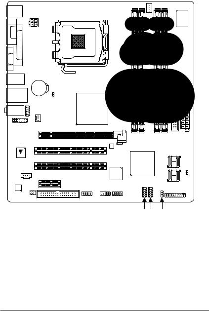
1-7 Connectors Introduction
|
1 |
3 |
|
|
18 |
6 |
|||||
|
9 |
2 |
|||||
|
11 |
||||||
|
14 |
||||||
|
4 |
7 |
|||||
|
12 |
19 |
|||||
|
13 |
5 |
17 |
16* |
15 |
8 |
10 |
|
1) |
ATX_12V |
11) |
F_AUDIO |
|
2) |
ATX (Power Connector) |
12) |
CD_IN |
|
3) |
CPU_FAN |
13) |
SPDIF_IO |
|
4) |
SYS_FAN |
14) |
HDA_SUR |
|
5) |
FDD |
15) |
F_USB1 / F_USB2 |
|
6) |
IDE |
16) |
F1_1394* / F2_1394* |
|
7) |
SATAII0 / 1 / 2 / 3 |
17) |
COMB |
|
|
PWR_LED |
18) |
CLR_CMOS |
|
9) |
BATTERY |
19) |
CI |
|
10) |
F_PANEL |
«*» Only for GA-945GMF-S2.
GA-945GM-S2 / GA-945GMF-S2 Motherboard — 20 —
![]()
1/2) ATX_12V / ATX (Power Connector)
With the use of the power connector, the power supply can supply enough stable power to all the components on the motherboard. Before connecting the power connector, please make sure that all components and devices are properly installed. Align the power connector with its proper location on the motherboard and connect tightly.
The ATX_12V power connector mainly supplies power to the CPU. If the ATX_12V power connector is not connected, the system will not start.
Caution!
Please use a power supply that is able to handle the system voltage requirements. It is recommended that a power supply that can withstand high power consumption be used (300W or greater). If a power supply is used that does not provide the required power, the result can lead to an unstable system or a system that is unable to start.
If you use a 24-pin ATX power supply, please remove the small cover on the power connector on the motherboard before plugging in the power cord ; otherwise, please do not remove it.
|
Pin No. |
Definition |
||
|
4 |
2 |
1 |
GND |
|
2 |
GND |
||
|
3 |
+12V |
||
|
3 |
1 |
4 |
+12V |
English
|
12 |
24 |
Pin No. |
Definition |
Pin No. |
Definition |
|
|
1 |
3.3V |
13 |
3.3V |
|||
|
2 |
3.3V |
14 |
-12V |
|||
|
3 |
GND |
15 |
GND |
|||
|
4 |
+5V |
16 |
PS_ON(soft On/Off) |
|||
|
5 |
GND |
17 |
GND |
|||
|
6 |
+5V |
18 |
GND |
|||
|
7 |
GND |
19 |
GND |
|||
|
8 |
Power Good |
20 |
-5V |
|||
|
9 |
5V SB(stand by +5V) |
21 |
+5V |
|||
|
10 |
+12V |
22 |
+5V |
|||
|
11 |
+12V(Only for 24-pin ATX) |
23 |
+5V (Only for 24-pin ATX) |
|||
|
1 |
13 |
12 |
3.3V(Only for 24-pin ATX) |
24 |
GND(Only for 24-pin ATX) |
|
— 21 — |
Hardware Installation |
English
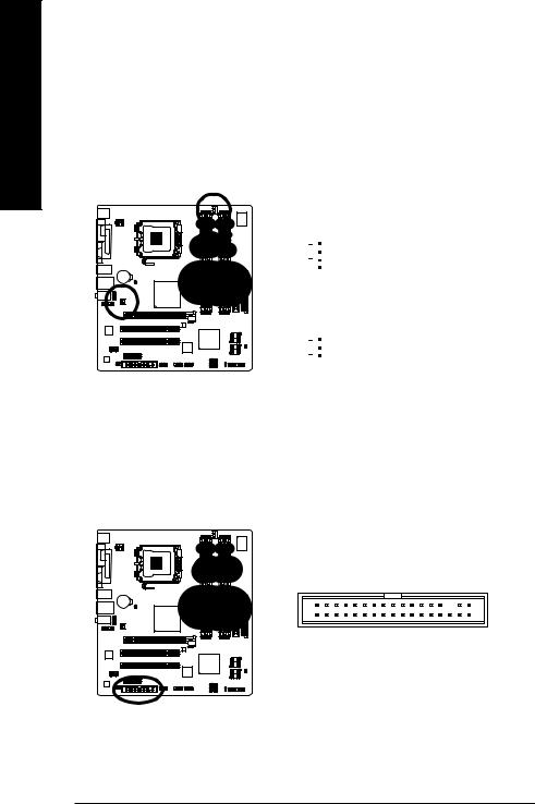
3/4) CPU_FAN / SYS_FAN (Cooler Fan Power Connector)
The cooler fan power connector supplies a +12V power voltage via a 3-pin/4-pin(CPU_FAN) power connector and possesses a foolproof connection design.
Most coolers are designed with color-coded power connector wires. A red power connector wire indicates a positive connection and requires a +12V power voltage. The black connector wire is the ground wire (GND).
Remember to connect the CPU/system fan cable to the CPU_FAN/SYS_FAN connector to prevent CPU damage or system hanging caused by overheating.
|
CPU_FAN : |
|||||
|
1 |
Pin No. |
Definition |
|||
|
1 |
GND |
||||
|
2 |
+12V / Speed Control |
||||
|
3 |
Sense |
||||
|
CPU_FAN |
|||||
|
4 |
Speed Control |
||||
|
1 |
SYS_FAN : |
||||
|
Pin No. |
Definition |
||||
|
1 |
GND |
||||
|
2 |
+12V |
||||
|
SYS_FAN |
|||||
|
3 |
Sense |
5)FDD (Floppy Connector)
The FDD connector is used to connect the FDD cable while the other end of the cable connects to the FDD drive. The types of FDD drives supported are: 360KB, 720KB, 1.2MB, 1.44MB and 2.88MB. Before attaching the FDD cable, please take note of the foolproof groove in the FDD connector.
GA-945GM-S2 / GA-945GMF-S2 Motherboard — 22 —

6)IDE (IDE Connector)
An IDE device connects to the computer via an IDE connector. One IDE connector can connect to one IDE cable, and the single IDE cable can then connect to two IDE devices (hard drive or optical drive). If you wish to connect two IDE devices, please set the jumper on one IDE device as Master and the other as Slave (for information on settings, please refer to the instructions located on the IDE device). Before attaching the IDE cable, please take note of the foolproof groove in the IDE connector.
40 39
7)SATAII0 / 1 / 2 / 3 (SATA 3Gb/s Connector, Controlled by ICH7)
SATA 3Gb/s can provide up to 300 MB/s transfer rate. Please refer to the BIOS setting for the SATA 3Gb/s and install the proper driver in order to work properly.
|
1 |
7 |
Pin No. |
Definition |
|
|
1 |
GND |
|||
|
SATAII2 |
SATAII3 |
2 |
TXP |
|
|
3 |
TXN |
|||
|
7 |
1 |
4 |
GND |
|
|
5 |
RXN |
|||
|
1 |
7 |
6 |
RXP |
|
|
7 |
GND |
|||
|
SATAII0 |
SATAII1 |
|||
|
7 |
1 |
English
|
— 23 — |
Hardware Installation |

English
 PWR_LED
The PWR_LED connector is connected with the system power indicator to indicate whether the system is on/off. It will blink when the system enters suspend mode.
|
Pin No. |
Definition |
|
|
1 |
MPD+ |
|
|
2 |
MPD- |
|
|
1 |
3 |
MPD- |
9) BATTERY
 Danger of explosion if battery is incorrectly replaced.
 Replace only with the same or equivalent type recommended by the manufacturer.
 Dispose of used batteries according to the manufacturer’s instructions.
If you want to erase CMOS…
1.Turn off the computer and unplug the power cord.
2.Gently take out the battery and put it aside for about one minute. (Or you can use a metal object to connect the positive and negative pins in the battery holder to make them short for five seconds.)
3.Re-install the battery.
4.Plug the power cord in and turn on the computer.
GA-945GM-S2 / GA-945GMF-S2 Motherboard — 24 —
 Loading…
You can only view or download manuals with
Sign Up and get 5 for free
Upload your files to the site. You get 1 for each file you add
Get 1 for every time someone downloads your manual
Buy as many as you need
-
Драйверы
14
-
Инструкции по эксплуатации
7
Языки:

Gigabyte GA-945GM-S2 инструкция по эксплуатации
(72 страницы)
- Языки:Венгерский, Греческий, Испанский, Итальянский, Немецкий, Польский, Португальский, Русский, Турецкий, Французский, Чешский
-
Тип:
PDF -
Размер:
18.6 MB -
Описание:
Installation Guidebook


На NoDevice можно скачать инструкцию по эксплуатации для Gigabyte GA-945GM-S2. Руководство пользователя необходимо для ознакомления с правилами установки и эксплуатации Gigabyte GA-945GM-S2. Инструкции по использованию помогут правильно настроить Gigabyte GA-945GM-S2, исправить ошибки и выявить неполадки.