-
Драйверы
17
-
Инструкции по эксплуатации
31
Языки:


Gigabyte GA-P55-UD3L инструкция по эксплуатации
(72 страницы)
- Языки:Венгерский, Греческий, Испанский, Итальянский, Немецкий, Польский, Португальский, Русский, Турецкий, Французский, Чешский
-
Тип:
PDF -
Размер:
18.6 MB -
Описание:
Installation Guidebook


На NoDevice можно скачать инструкцию по эксплуатации для Gigabyte GA-P55-UD3L. Руководство пользователя необходимо для ознакомления с правилами установки и эксплуатации Gigabyte GA-P55-UD3L. Инструкции по использованию помогут правильно настроить Gigabyte GA-P55-UD3L, исправить ошибки и выявить неполадки.
-
Contents
-
Table of Contents
-
Troubleshooting
-
Bookmarks
Quick Links
GA-P55-UD3L-TPM/
GA-P55-UD3L/
GA-P55-US3L
LGA1156 socket motherboard for Intel
Core
i7 processor family/
®
™
Intel
Core
i5 processor family
®
™
User’s Manual
Rev. 1101
12ME-P55UD3L-1101R
Related Manuals for Gigabyte GA-P55-UD3L
Summary of Contents for Gigabyte GA-P55-UD3L
-
Page 1
GA-P55-UD3L-TPM/ GA-P55-UD3L/ GA-P55-US3L LGA1156 socket motherboard for Intel Core i7 processor family/ ® ™ Intel Core i5 processor family ® ™ User’s Manual Rev. 1101 12ME-P55UD3L-1101R… -
Page 4: Identifying Your Motherboard Revision
GIGABYTE’s prior written permission. Documentation Classifications In order to assist in the use of this product, GIGABYTE provides the following types of documentations: For quick set-up of the product, read the Quick Installation Guide included with the product.
-
Page 5: Table Of Contents
Table of Contents Box Contents ……………………7 Optional Items …………………….7 GA-P55-UD3L-TPM/GA-P55-UD3L/GA-P55-US3L Motherboard Layout …….8 Block Diagram …………………….9 Chapter 1 Hardware Installation ………………. 11 Installation Precautions ……………… 11 1-2 Product Specifications ………………12 Installing the CPU and CPU Cooler …………… 15 1-3-1 Installing the CPU ………………..15 1-3-2 Installing the CPU Cooler ………………17 Installing the Memory ………………
-
Page 6
Auto Green ………………… 82 eXtreme Hard Drive (X.H.D) …………….83 Chapter 5 Appendix ………………….85 5-1 Configuring SATA Hard Drive(s) …………..85 5-1-1 Configuring Intel P55 SATA Controllers …………..85 5-1-2 Configuring GIGABYTE SATA2 SATA Controller …………93 5-1-3 Making a SATA RAID/AHCI Driver Diskette …………99 5-1-4 Installing the SATA RAID/AHCI Driver and Operating System ……100 5-2 Configuring Audio Input and Output …………..111… -
Page 7: Box Contents
Box Contents GA-P55-UD3L-TPM, GA-P55-UD3L, or GA-P55-US3L motherboard Motherboard driver disk User’s Manual Quick Installation Guide One IDE cable Two SATA 3Gb/s cables I/O Shield • The box contents above are for reference only and the actual items shall depend on the product package you obtain. The box contents are subject to change without notice.
-
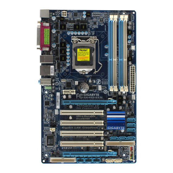
Page 8: Ga-P55-Ud3L-Tpm/Ga-P55-Ud3L/Ga-P55-Us3L Motherboard Layout
SATA2_0 CD_IN TPM IC j SATA2_1 PCI3 SPDIF_I SATA2_2 SATA2_5 SATA2_4 SATA2_3 PCI4 CLR_CMOS PCIEX4 GIGABYTE M_BIOS F_PANEL SATA2 F_USB3 F_USB2 F_USB1 GSATA2_0 GSATA2_1 «*» The GA-P55-UD3L-TPM/GA-P55-UD3L adopts All-Solid Capacitor design. Only for GA-P55-UD3L-TPM. (Note) Due to a hardware limitation, the PCIEX1 slot can only accommodate a shorter PCI Express x1 expansion card.
-
Page 9: Block Diagram
PCI Express Bus Intel ® Dual BIOS PCIe CLK (100 MHz) 6 SATA 3Gb/s 1 PCI Express x1 14 USB Ports 2 SATA 3Gb/s GIGABYTE SATA2 ATA-133/100/66/33 IDE Channel LPC Bus Floppy PCI Bus IT8720 COM Port CODEC PS/2 KB/Mouse…
-
Page 10
— 10 -… -
Page 11: Chapter 1 Hardware Installation
Chapter 1 Hardware Installation Installation Precautions The motherboard contains numerous delicate electronic circuits and components which can become damaged as a result of electrostatic discharge (ESD). Prior to installation, carefully read the user’s manual and follow these procedures: • Prior to installation, do not remove or break motherboard S/N (Serial Number) sticker or warranty sticker provided by your dealer.
-
Page 12: Product Specifications
Core i5 series processor ® ™ ® ™ in the LGA1156 package (Go to GIGABYTE’s website for the latest CPU support list.) L3 cache varies with CPU Chipset Intel P55 Express Chipset ® Memory 4 x 1.5V DDR3 DIMM sockets supporting up to 16 GB of system memory…
-
Page 13
Chipset Up to 14 USB 2.0/1.1 ports (8 on the back panel, 6 via the USB brackets connected to the internal USB headers) Internal 1 x 24-pin ATX main power connector Connectors 1 x 4-pin ATX 12V power connector … -
Page 14
Unique Features Support for @BIOS Support for Q-Flash Support for Xpress BIOS Rescue Support for Download Center Support for Xpress Install Support for Xpress Recovery2 Support for EasyTune (Note 6) Support for Dynamic Energy Saver ™… -
Page 15: Installing The Cpu And Cpu Cooler
Read the following guidelines before you begin to install the CPU: • Make sure that the motherboard supports the CPU. (Go to GIGABYTE’s website for the latest CPU support list.) • Always turn off the computer and unplug the power cord from the power outlet before installing the CPU to prevent hardware damage.
-
Page 16
B. Follow the steps below to correctly install the CPU into the motherboard CPU socket. Before installing the CPU, make sure to turn off the computer and unplug the power cord from the power outlet to prevent damage to the CPU. Step 1: Step 2: Gently press the CPU socket lever handle down… -
Page 17: Installing The Cpu Cooler
1-3-2 Installing the CPU Cooler Follow the steps below to correctly install the CPU cooler on the motherboard. (The following procedure uses Intel boxed cooler as the example cooler.) ® Male Push Direction of the Arrow Sign on The Top the Male Push of Female Push Pin…
-
Page 18: Installing The Memory
• Make sure that the motherboard supports the memory. It is recommended that memory of the same capacity, brand, speed, and chips be used. (Go to GIGABYTE’s website for the latest memory support list.) • Always turn off the computer and unplug the power cord from the power outlet before installing the memory to prevent hardware damage.
-
Page 19: Installing A Memory
1-4-2 Installing a Memory Before installing a memory module, make sure to turn off the computer and unplug the power cord from the power outlet to prevent damage to the memory module. DDR3 and DDR2 DIMMs are not compatible to each other or DDR DIMMs. Be sure to install DDR3 DIMMs on this motherboard.
-
Page 20: Installing An Expansion Card
Installing an Expansion Card Read the following guidelines before you begin to install an expansion card: • Make sure the motherboard supports the expansion card. Carefully read the manual that came with your expansion card. • Always turn off the computer and unplug the power cord from the power outlet before installing an expansion card to prevent hardware damage.
-
Page 21: Back Panel Connectors
Back Panel Connectors USB 2.0/1.1 Port The USB port supports the USB 2.0/1.1 specification. Use this port for USB devices such as a USB key- board/mouse, USB printer, USB flash drive and etc. PS/2 Keyboard/Mouse Port Use this port to connect a PS/2 keyboard or mouse. Parallel Port Use the parallel port to connect devices such as a printer, scanner and etc. The parallel port is also called a printer port.
-
Page 22
Line In Jack (Blue) The default line in jack. Use this audio jack for line in devices such as an optical drive, walkman, etc. Line Out Jack (Green) The default line out jack. Use this audio jack for a headphone or 2-channel speaker. This jack can be used to connect front speakers in a 4/5.1-channel audio configuration. -
Page 23: Internal Connectors
Internal Connectors ATX_12V F_PANEL CPU_FAN F_AUDIO SYS_FAN1/2 CD_IN PWR_FAN SPDIF_I SPDIF_O F_USB1/F_USB2/F_USB3 SATA2_0/1/2/3/4/5 CLR_CMOS GSATA2_0/1 PHASE_LED Read the following guidelines before connecting external devices: • First make sure your devices are compliant with the connectors you wish to connect. • Before installing the devices, be sure to turn off the devices and your computer. Unplug the power cord from the power outlet to prevent damage to the devices.
-
Page 24
1/2) ATX_12V/ATX (2×2 12V Power Connector and 2×12 Main Power Connector) With the use of the power connector, the power supply can supply enough stable power to all the components on the motherboard. Before connecting the power connector, first make sure the power supply is turned off and all devices are properly installed. -
Page 25: Fdd (Floppy Disk Drive Connector)
3/4/5) CPU_FAN/SYS_FAN1/SYS_FAN2/PWR_FAN (Fan Headers) The motherboard has a 4-pin CPU fan header (CPU_FAN), a 4-pin (SYS_FAN2) and a 3-pin (SYS_ FAN1) system fan headers, and a 3-pin power fan header (PWR_FAN). Most fan headers possess a foolproof insertion design. When connecting a fan cable, be sure to connect it in the correct orientation (the black connector wire is the ground wire).
-
Page 26
7) IDE (IDE Connector) The IDE connector supports up to two IDE devices such as hard drives and optical drives. Before attach- ing the IDE cable, locate the foolproof groove on the connector. If you wish to connect two IDE devices, remember to set the jumpers and the cabling according to the role of the IDE devices (for example, master or slave). (For information about configuring master/slave settings for the IDE devices, read the instructions from the device manufacturers.) -
Page 27: Bat Battery
9) GSATA2_0/1 (SATA 3Gb/s Connectors, Controlled by GIGABYTE SATA2) The SATA connectors conform to SATA 3Gb/s standard and are compatible with SATA 1.5Gb/s standard. Each SATA connector supports a single SATA device. The GIGABYTE SATA2 controller supports RAID 0, RAID 1, and JBOD. Refer to Chapter 5, «Configuring SATA Hard Drive(s),» for instructions on configuring a RAID array.
-
Page 28: F_Panel Front Panel Header
11) F_PANEL (Front Panel Header) Connect the power switch, reset switch, speaker, chassis intrusion switch/sensor and system status indicator on the chassis to this header according to the pin assignments below. Note the positive and negative pins before connecting the cables. SPEAK- PWR- Power LED…
-
Page 29: Cd In Connector
12) F_AUDIO (Front Panel Audio Header) The front panel audio header supports Intel High Definition audio (HD) and AC’97 audio. You may connect your chassis front panel audio module to this header. Make sure the wire assignments of the module con- nector match the pin assignments of the motherboard header. Incorrect connection between the module connector and the motherboard header will make the device unable to work or even damage it. For HD Front Panel Audio: For AC’97 Front Panel Audio: Pin No. Definition…
-
Page 30: S/Pdif Out Header
14) SPDIF_I (S/PDIF In Header) This header supports digital S/PDIF In and can connect to an audio device that supports digital audio out via an optional S/PDIF In cable. For purchasing the optional S/PDIF In cable, please contact the local dealer.
-
Page 31: Clearing Cmos Jumper
16) F_USB1/F_USB2/F_USB3 (USB Headers) The headers conform to USB 2.0/1.1 specification. Each USB header can provide two USB ports via an optional USB bracket. For purchasing the optional USB bracket, please contact the local dealer. Pin No. Definition Power (5V) Power (5V) USB DX- USB DY- USB DX+ USB DY+ No Pin • Do not plug the IEEE 1394 bracket (2×5-pin) cable into the USB header. •…
-
Page 32
18) PHASE LED The number of lighted LEDs indicates the CPU loading. The higher the CPU loading, the more the number of lighted LEDs. To enable the Phase LED display function, please first enable Dynamic Energy Saver 2. Refer to Chapter 4, «Dynamic Energy Saver 2,» for more details. ™ ™ Hardware Installation — 32 -… -
Page 33: Chapter 2 Bios Setup
To see more advanced BIOS Setup menu options, you can press <Ctrl> + <F1> in the main menu of the BIOS Setup program. To upgrade the BIOS, use either the GIGABYTE Q-Flash or @BIOS utility. Q-Flash allows the user to quickly and easily upgrade or back up BIOS without entering the operating •…
-
Page 34: Startup Screen
Startup Screen The following screens may appear when the computer boots. A. The LOGO Screen (Default) Function Keys B. The POST Screen Award Modular BIOS v6.00PG, An Energy Star Ally Copyright (C) 1984-2009, Award Software, Inc. P55-UD3L D11 Motherboard Model BIOS Version Function Keys <DEL>: BIOS Setup <F9>: XpressRecovery2 <F12>: Boot Menu <End>: Qflash…
-
Page 35: The Main Menu
The Main Menu Once you enter the BIOS Setup program, the Main Menu (as shown below) appears on the screen. Use ar- row keys to move among the items and press <Enter> to accept or enter a sub-menu. (Sample BIOS Version: GA-P55-UD3L D11) CMOS Setup Utility-Copyright (C) 1984-2009 Award Software MB Intelligent Tweaker(M.I.T.) Load Optimized Defaults…
-
Page 36: Standard Cmos Features
The Functions of the <F11> and <F12> keys (For the Main Menu Only) F11: Save CMOS to BIOS This function allows you to save the current BIOS settings to a profile. You can create up to 8 profiles (Profile 1-8) and name each profile. First enter the profile name (to erase the default profile name, use the SPACE key) and then press <Enter> to complete. F12: Load CMOS from BIOS If your system becomes unstable and you have loaded the BIOS default settings, you can use this function to load the BIOS settings from a profile created before, without the hassles of reconfiguring the BIOS settings. First select the profile you wish to load, then press <Enter> to complete.
-
Page 37: Mb Intelligent Tweaker(M.i.t.)
MB Intelligent Tweaker(M.I.T.) CMOS Setup Utility-Copyright (C) 1984-2009 Award Software MB Intelligent Tweaker(M.I.T.) Item Help M.I.T Current Status [Press Enter] Menu Level Advanced Frequency Settings [Press Enter] Advanced Memory Settings [Press Enter] Advanced Voltage Settings [Press Enter] …
-
Page 38: Cpu Frequency
CPU Clock Ratio (Note) Allows you to alter the clock ratio for the installed CPU. The item is present only if a CPU with unlocked clock ratio is installed. CPU Frequency Displays the current operating CPU frequency. Advanced CPU Core Features CMOS Setup Utility-Copyright (C) 1984-2009 Award Software Advanced CPU Core Features Item Help…
-
Page 39
C3/C6/C7 State Support (Note) Allows you to determine whether to let the CPU enter C3/C6/C7 mode in system halt state. When en- abled, the CPU core frequency and voltage will be reduced during system halt state to decrease power consumption. The C3/C6/C7 state is a more enhanced power-saving state than C1. Auto lets the BIOS automatically configure this setting. (Default: Auto) CPU Thermal Monitor (Note) -
Page 40
>>>>> Standard Clock Control Base Clock(BCLK) Control Enables or disables the control of CPU base clock. Enabled will allow the BCLK Frequency(Mhz) item below to be configurable. Note: If your system fails to boot after overclocking, please wait for 20 seconds to allow for automated system reboot, or clear the CMOS values to reset the board to default values. (Default: Disabled) BCLK Frequency(Mhz) Allows you to manually set the CPU base clock. -
Page 41: Cpu Clock Skew
>>>>> Advanced Clock Control CPU Clock Drive Allows you to adjust the amplitude of the CPU and Chipset clock. Options are: 700mV (default), 800mV, 900mV, 1000mV. PCI Express Clock Drive Allows you to adjust the amplitude of the PCI Express and Chipset clock. Options are: 700mV (default), 800mV, 900mV, 1000mV.
-
Page 42: Channel Interleaving
Performance Enhance Allows the system to operate at three different performance levels. Standard Lets the system operate at its basic performance level. Turbo Lets the system operate at its good performance level. (Default) Extreme Lets the system operate at its best performance level. DRAM Timing Selectable (SPD) Quick and Expert allows the Channel Interleaving and Rank Interleaving items to be configurable.
-
Page 43
Options are: Auto (default), 1~15. tRAS Options are: Auto (default), 1~31. >>>>> Channel A/B Advanced Timing Control Options are: Auto (default), 1~63. tRRD Options are: Auto (default), 1~7. tWTR Options are: Auto (default), 1~31. Options are: Auto (default), 1~15. tWTP Options are: Auto (default), 1~31. -
Page 44
>>>>> Channel A/B Turnaround Settings CMOS Setup Utility-Copyright (C) 1984-2009 Award Software Channel A Turnaround Settings Item Help >>>>> Channel A Reads Followed by Reads Menu Level x Different DIMMs Auto x Different Ranks Auto x On The Same Rank Auto >>>>>… -
Page 45
Advanced Voltage Settings CMOS Setup Utility-Copyright (C) 1984-2009 Award Software Advanced Voltage Settings Item Help ****** Mother Board Voltage Control ****** Menu Level Voltage Types Normal Current —————————————————————————— >>> CPU Load-Line Calibration [Disabled] CPU Vcore 1.11250V [Auto] QPI/Vtt Voltage 1.150V [Auto] >>>… -
Page 46: Miscellaneous Settings
Miscellaneous Settings CMOS Setup Utility-Copyright (C) 1984-2009 Award Software Miscellaneous Settings Item Help Isochronous Support [Enabled] Menu Level higf : Move Enter: Select +/-/PU/PD: Value F10: Save ESC: Exit F1: General Help F5: Previous Values F6: Fail-Safe Defaults F7: Optimized Defaults Isochronous Support Determines whether to enable specific streams within the CPU and Chipset. (Default: Enabled)
-
Page 47: Standard Cmos Features
Standard CMOS Features CMOS Setup Utility-Copyright (C) 1984-2009 Award Software Standard CMOS Features Item Help Date (mm:dd:yy) Wed, Jul 15 2009 Menu Level Time (hh:mm:ss) 22:31:24 IDE Channel 0 Master [None] IDE Channel 0 Slave [None] IDE Channel 1 Master [None] …
-
Page 48
Lets the BIOS automatically detect IDE/SATA devices during the POST. (Default) • Auto If no IDE/SATA devices are used, set this item to None so the system will skip • None the detection of the device during the POST for faster system startup. Allows you to manually enter the specifications of the hard drive when the hard • Manual drive access mode is set to CHS. -
Page 49: Advanced Bios Features
Advanced BIOS Features CMOS Setup Utility-Copyright (C) 1984-2009 Award Software Advanced BIOS Features Item Help Hard Disk Boot Priority [Press Enter] Menu Level Quick Boot [Disabled] First Boot Device [Hard Disk] Second Boot Device [CDROM] Third Boot Device [Floppy] Password Check [Setup]…
-
Page 50: Init Display First
Allows you to set a delay time for the BIOS to initialize the hard drive as the system boots up. The ad- justable range is from 0 to 15 seconds. (Default: 0) Full Screen LOGO Show Allows you to determine whether to display the GIGABYTE Logo at system startup. Disabled displays normal POST message. (Default: Enabled) Backup BIOS Image to HDD Allows the system to copy the BIOS image file to the hard drive. If the system BIOS is corrupted, it will…
-
Page 51: Integrated Peripherals
Integrated Peripherals CMOS Setup Utility-Copyright (C) 1984-2009 Award Software Integrated Peripherals Item Help SATA RAID/AHCI Mode [Disabled] Menu Level SATA Port0-3 Native Mode [Enabled] USB Controllers [Enabled] USB Legacy Function [Enabled] USB Storage Function [Enabled] Azalia Codec [Auto] Onboard H/W LAN [Enabled] Green LAN [Disabled]…
-
Page 52
Azalia Codec Enables or disables the onboard audio function. (Default: Auto) If you wish to install a 3rd party add-in audio card instead of using the onboard audio, set this item to Disabled. Onboard H/W LAN Enables or disables the onboard LAN function. (Default: Enabled) If you wish to install a 3rd party add-in network card instead of using the onboard LAN, set this item to Disabled. -
Page 53: Onboard Parallel Port
Allows you to decide whether to activate the boot ROM integrated with the onboard LAN chip. (Default: Disabled) Onboard SATA/IDE Device (GIGABYTE SATA2, IDE and GSATA2_0/1 Connectors) Enables or disables the IDE and SATA controllers integrated in the GIGABYTE SATA2 chip. (Default: Enabled) Onboard SATA/IDE Ctrl Mode (GIGABYTE SATA2, IDE and GSATA2_0/1 Connectors) Enables or disables RAID for the SATA controller integrated in the GIGABYTE SATA2 chip or configures the SATA controller to AHCI mode.
-
Page 54: Power Management Setup
Power Management Setup CMOS Setup Utility-Copyright (C) 1984-2009 Award Software Power Management Setup Item Help ACPI Suspend Type [S3(STR)] Menu Level Soft-Off by PWR-BTTN [Instant-Off] PME Event Wake Up [Enabled] Power On by Ring [Enabled] Resume by Alarm [Disabled] Date (of Month) Alarm Everyday Time (hh:mm:ss) Alarm…
-
Page 55: Eup Support
Resume by Alarm Determines whether to power on the system at a desired time. (Default: Disabled) If enabled, set the date and time as following: Date (of Month) Alarm: Turn on the system at a specific time on each day or on a specific day in a month. Time (hh: mm: ss) Alarm: Set the time at which the system will be powered on automatically. Note: When using this function, avoid inadequate shutdown from the operating system or removal of the AC power, or the settings may not be effective.
-
Page 56: Pc Health Status
PC Health Status CMOS Setup Utility-Copyright (C) 1984-2009 Award Software PC Health Status Item Help Reset Case Open Status [Disabled] Menu Level Case Opened Vcore 1.220V DDR15V 1.504V 4.972V +12V 12.048V Current System Temperature Current CPU Temperature Current CPU FAN Speed 3375 RPM Current SYSTEM FAN2 Speed 0 RPM…
-
Page 57
CPU Smart FAN Mode Specifies how to control CPU fan speed. This item is configurable only if CPU Smart FAN Control is set to Enabled. Auto Lets the BIOS automatically detect the type of CPU fan installed and sets the optimal CPU fan control mode. (Default) Voltage Sets Voltage mode for a 3-pin CPU fan. Sets PWM mode for a 4-pin CPU fan. -
Page 58: Load Fail-Safe Defaults
Load Fail-Safe Defaults CMOS Setup Utility-Copyright (C) 1984-2009 Award Software MB Intelligent Tweaker(M.I.T.) Load Optimized Defaults Standard CMOS Features Set Supervisor Password Advanced BIOS Features Set User Password Integrated Peripherals Save & Exit Setup Power Management Setup Exit Without Saving …
-
Page 59: Set Supervisor/User Password
2-11 Set Supervisor/User Password CMOS Setup Utility-Copyright (C) 1984-2009 Award Software MB Intelligent Tweaker(M.I.T.) Load Optimized Defaults Standard CMOS Features Set Supervisor Password Advanced BIOS Features Set User Password Integrated Peripherals Save & Exit Setup Power Management Setup Exit Without Saving …
-
Page 60: Save & Exit Setup
2-12 Save & Exit Setup CMOS Setup Utility-Copyright (C) 1984-2009 Award Software MB Intelligent Tweaker(M.I.T.) Load Optimized Defaults Standard CMOS Features Set Supervisor Password Advanced BIOS Features Set User Password Integrated Peripherals Save & Exit Setup Power Management Setup Exit Without Saving …
-
Page 61: Security Chip Configuration
2-14 Security Chip Configuration CMOS Setup Utility-Copyright (C) 1984-2009 Award Software Security Chip Configuration Item Help Security Chip [Disabled] Menu Level Security Chip State Disabled/Deactivated higf : Move Enter: Select +/-/PU/PD: Value F10: Save ESC: Exit F1: General Help F5: Previous Values F6: Fail-Safe Defaults F7: Optimized Defaults Security Chip…
-
Page 62
BIOS Setup — 62 -… -
Page 63: Chapter 3 Drivers Installation
Chapter 3 Drivers Installation • Before installing the drivers, first install the operating system. • After installing the operating system, insert the motherboard driver disk into your optical drive. The driver Autorun screen is automatically displayed which looks like that shown in the screen shot below. (If the driver Autorun screen does not appear automatically, go to My Computer, double-click the optical drive and execute the Run.exe program.) Installing Chipset Drivers After inserting the driver disk, «Xpress Install»…
-
Page 64: Application Software
Application Software This page displays all the utilities and applications that GIGABYTE develops and some free software. You can click the Install button on the right of an item to install it. Technical Manuals This page provides GIGABYTE’s application guides, content descriptions for this driver disk, and the mother- board manuals.
-
Page 65: Contact
Contact For the detailed contact information of the GIGABYTE Taiwan headquarter or worldwide branch offices, click the URL on this page to link to the GIGABYTE website. System This page provides the basic system information. — 65 — Drivers Installation…
-
Page 66: Download Center
The latest version of the BIOS, drivers, or applications will be displayed. New Utilities This page provides a quick link to GIGABYTE’s lately developed utilities for users to install. You can click the Install button on the right of an item to install it.
-
Page 67: Chapter 4 Unique Features
Chapter 4 Unique Features Xpress Recovery2 Xpress Recovery2 is a utility that allows you to quickly compress and back up your system data and perform restoration of it. Supporting NTFS, FAT32, and FAT16 file systems, Xpress Recovery2 can back up data on PATA and SATA hard drives and restore it.
-
Page 68
Step 3: Step 4: When partitioning your hard drive, make sure to After the operating system is installed, right-click the Computer icon on your desktop and select leave unallocated space (10 GB or more is recom- mended; actual size requirements vary, depending Manage. -
Page 69
D. Using the Restore Function in Xpress Recovery2 Select RESTORE to restore the backup to your hard drive in case the system breaks down. The RESTORE option will not be present if no backup is created before. E. Removing the Backup Step 1: Step 2: If you wish to remove the backup file, select… -
Page 70: Bios Update Utilities
BIOS Update Utilities GIGABYTE motherboards provide two unique BIOS update tools, Q-Flash and @BIOS . GIGABYTE ™ ™ Q-Flash and @BIOS are easy-to-use and allow you to update the BIOS without the need to enter MS-DOS mode. Additionally, this motherboard features the DualBIOS design, which enhances protection for the ™…
-
Page 71
B. Updating the BIOS When updating the BIOS, choose the location where the BIOS file is saved. The following procedure as- sumes that you save the BIOS file to a floppy disk. Step 1: 1. Insert the floppy disk containing the BIOS file into the floppy disk drive. In the main menu of Q-Flash, use the up or down arrow key to select Update BIOS from Drive and press <Enter>. •… -
Page 72
Step 4: Press <Esc> and then <Enter> to exit Q-Flash and reboot the system. As the system boots, you should see the new BIOS version is present on the POST screen. Step 5: During the POST, press <Delete> to enter BIOS Setup. Select Load Optimized Defaults and press <Enter> to load BIOS defaults. -
Page 73: Updating The Bios With The @Bios Utility
BIOS or a system that is unable to start. Do not use the G.O.M. (GIGABYTE Online Management) function when using @BIOS. GIGABYTE product warranty does not cover any BIOS damage or system failure resulting from an inad- equate BIOS flashing.
-
Page 74: Easytune 6
EasyTune 6 GIGABYTE’s EasyTune 6 is a simple and easy-to-use interface that allows users to fine-tune their system settings or do overclock/overvoltage in Windows environment. The user-friendly EasyTune 6 interface also includes tabbed pages for CPU and memory information, letting users read their system-related information without the need to install additional software. The EasyTune 6 Interface…
-
Page 75: Dynamic Energy Saver ™ 2
The Dynamic Energy Saver 2 Interface ™ A. Meter Mode In Meter Mode, GIGABYTE Dynamic Energy Saver 2 shows how much power they have saved in a set pe- ™ riod of time. 12 13 14 Meter Mode — Button Information Table…
-
Page 76
B. Total Mode In Total Mode, users are able to see how much total power savings they have accumulated in a set period of time since activating Dynamic Energy Saver 2 for the first time ™ (Note 3) 11 12 13 Total Mode — Button Information Table Button Description Dynamic Energy Saver On/Off Switch (Default: Off) Current CPU Power Consumption… -
Page 77: Q-Share
Q-Share, you are able to share your data with computers on the same network, making full use of Internet resources. Directions for using Q-Share After installing Q-Share from the motherboard driver disk, go to Start>All Programs>GIGABYTE>Q-Share. exe to launch the Q-Share tool. Find the Q-Share icon in the notification area and right-click on this icon to configure the data sharing settings.
-
Page 78: Smart 6
Smart 6 ™ GIGABYTE Smart 6 is designed with user-friendliness in mind, and offers a combination of 6 innovative ™ (Note 1) software utilities that provide easier and smarter PC system management. Smart 6 allows you to speed up ™…
-
Page 79: Smart Recovery
SMART Recovery With SMART Recovery, users can quickly create backups of changed data files or copy (Note 2) files from a specific backup on PATA and SATA hard drives (partitioned on NTFS file system) in Windows Vista. Instructions: In the main menu, click the Config button to open the Smart Recov- ery Preference dialog box. The Smart Recovery Preference dialog box: Button Function Enable…
-
Page 80: Smart Timelock
SMART Recorder SMART Recorder monitors and records the activities in a system such as the time when the computer was turned on/off or even when large data files were moved within the hard drive or copied to an external storage device (Note 5) Instructions: Select the Enable check box at the bottom of the ON/OFF Recorder or File Monitor tab to enable the recording of system on/off time or files copying. Entering the Smart 6 password is required before you…
-
Page 81: Smart Tpm J
• Though the TPM delivers the latest data security technology, it does not guarantee data integrity or provide hardware protection. GIGABYTE is not liable for loss of encrypted data as a result of hardware damage. A. Before installing Smart TPM, follow the steps below in sequence: Step 1: As the computer starts, enter the BIOS Setup program.
-
Page 82: Auto Green
Auto Green Auto Green is an easy-to-use tool that provides users with simple options to enable system power savings via a Bluetooth cell phone. When the phone is out of the range of the computer’s Bluetooth receiver, the sys- tem will enter the specified power saving mode. The Configuration dialog box: First, you have to set your Bluetooth cell phone as a portable key.
-
Page 83: Extreme Hard Drive (X.h.d)
After installing the operating system, insert the motherboard driver disk. You can click the Xpress Install All button to automatically install all motherboard drivers, including the X.H.D utility. Or you can go to the Applica- tion Software screen to individually install the X.H.D utility later. B. Using GIGABYTE eXtreme Hard Drive (X.H.D) (Note 2) Instructions: Before launching X.H.D, make sure the newly added hard-…
-
Page 84
Unique Features — 84 -… -
Page 85: Chapter 5 Appendix
Chapter 5 Appendix Configuring SATA Hard Drive(s) To configure SATA hard drive(s), follow the steps below: A. Install SATA hard drive(s) in your computer. B. Configure SATA controller mode in BIOS Setup. C. Configure a RAID array in RAID BIOS. (Note 1) D. Make a floppy disk containing the SATA RAID/AHCI driver for Windows XP. (Note 2) E. Install the SATA RAID/AHCI driver and operating system. (Note 2) Before you begin Please prepare:…
-
Page 86
B. Configuring SATA controller mode in BIOS Setup Make sure to configure the SATA controller mode correctly in system BIOS Setup. Step 1: Turn on your computer and press <Delete> to enter BIOS Setup during the POST (Power-On Self-Test). To create RAID, set SATA RAID/AHCI Mode under the Integrated Peripherals menu to RAID (Figure 1) (Disabled by default). -
Page 87
C. Configuring a RAID array in RAID BIOS Enter the RAID BIOS setup utility to configure a RAID array. Skip this step and proceed with the installation of Windows operating system for a non-RAID configuration. Step 1: After the POST memory test begins and before the operating system boot begins, look for a message which says «Press <Ctrl-I> to enter Configuration Utility» (Figure 2). Press <Ctrl> + <I> to enter the P55 RAID Con- figuration Utility. Intel(R) Matrix Storage Manager option ROM v8.9.0.1023 PCH-D wRAID5 Copyright(C) 2003-09 Intel Corporation. -
Page 88
Step 3: After entering the CREATE VOLUME MENU screen, enter a volume name with 1~16 letters (letters cannot be special characters) under the Name item and press <Enter>. Then, select a RAID level (Figure 4). RAID levels supported include RAID 0, RAID 1, Recovery, RAID 10, and RAID 5 (the selections available depend on the number of the hard drives being installed). -
Page 89
Step 5: Enter the array capacity and press <Enter>. Finally press <Enter> on the Create Volume item to begin creat- ing the RAID array. When prompted to confirm whether to create this volume, press <Y> to confirm or <N> to cancel (Figure 6). Intel(R) Matrix Storage Manager option ROM v8.9.0.1023 PCH-D wRAID5 Copyright(C) 2003-09 Intel Corporation. All Rights Reserved. [ CREATE VOLUME MENU ] Name : Volume0 RAID Level : RAID0(Stripe) -
Page 90
Recovery Volume Options Intel Rapid Recover Technology provides data protection by allowing users to easily restore data and system operation using a designated recovery drive. With the Rapid Recovery Technology, which employs RAID 1 functionality, users can copy the data from the master drive to the recovery drive; if needed, the data on the recovery drive can be restored back to the master drive. -
Page 91
Step 3: Press <Enter> under the Select Disks item. In the SELECT DISKS box, press <Tab> on the hard drive you want to use for the master drive and press <Space> on the hard drive you want to use for the recovery drive. (Make sure the recovery drive has equal or larger capacity than the master drive.) Then press <Enter>… -
Page 92
Delete RAID Volume To delete a RAID array, select Delete RAID Volume in MAIN MENU and press <Enter>. In the DELETE VOLUME MENU section, use the up or down arrow key to select the array to be deleted and press <Delete>. When prompted to confirm your selection (Figure 12), press <Y> to confirm or <N> to abort. -
Page 93: Configuring Gigabyte Sata2 Sata Controller
Attach one end of the SATA signal cable to the rear of the SATA hard drive and the other end to available SATA port on the motherboard. On this motherboard, the GSATA2_0 and GSATA2_1 ports are supported by the GIGABYTE SATA2 SATA controller. Then connect the power connector from your power supply to the hard drive.
-
Page 94
After the POST memory test begins and before the operating system boot begins, look for a message which says «Press <Ctrl-G> to enter RAID Setup Utility» (Figure 2). Press <Ctrl> + <G> to enter the RAID setup util- ity. GIGABYTE Technology Corp. PCI Express to SATAII HOST Controller ROM v1.07.06 Copyright (C) 2005-2009 Gigabyte Technology Corp. (http://www.gigabyte.com) -
Page 95
In the main screen, press <Enter> on the Create RAID Disk Drive item. Then the Create New RAID screen appears (Figure 4). Gigabyte Technology Corp. RAID Setup Utility v1.07.06 [ Create New RAID ] [ Hard Disk Drive List ]… -
Page 96
4. Set Block Size (RAID 0 only): Under the Block item, use the up or down arrow key to select the stripe block size (Figure 6), ranging from 4 KB to 128 KB. Press <Enter>. Gigabyte Technology Corp. RAID Setup Utility v1.07.06 [ Create New RAID ]… -
Page 97
When finished, the new RAID array will be displayed in the RAID Disk Drive List block (Figure 8). Gigabyte Technology Corp. RAID Setup Utility v1.07.06 [ Main Menu ] [ Hard Disk Drive List ] Create RAID Disk Drive Model Name Capacity Type/Status Delete RAID Disk Drive HDD0: ST3120026AS 120 GB… -
Page 98
7. Save and Exit Setup: After configuring the RAID array, select the Save And Exit Setup item in the main screen to save your settings before exiting the RAID BIOS utility, then press <Y> (Figure 10). Gigabyte Technology Corp. RAID Setup Utility v1.07.06 [ Main Menu ] [ Hard Disk Drive List ]… -
Page 99: Making A Sata Raid/Ahci Driver Diskette
2) Intel Matrix Storage driver for 64bit system for Windows 64-bit. • For the GIGABYTE SATA2, select 3) GIGABYTE GSATA driver for 32bit system for Windows 32-bit operating system or 4) GIGABYTE GSATA driver for 64bit system for Windows 64-bit.
-
Page 100: Installing The Sata Raid/Ahci Driver And Operating System
5-1-4 Installing the SATA RAID/AHCI Driver and Operating System With the SATA RAID/AHCI driver diskette and correct BIOS settings, you are ready to install Windows Vista/ XP onto your hard drive(s). The followings are examples of Windows XP and Vista installation. A.
-
Page 101
For the GIGABYTE SATA2: Insert the floppy disk containing the SATA RAID/AHCI driver and press <S>. Then a controller menu similar to Figure 3 below will appear. Select (Windows XP/2003) RAID/AHCI Driver for GIGABYTE GBB36X Con- troller and press <Enter>. Windows Setup You have chosen to configure a SCSI Adapter for use with Windows, using a device support disk provided by an adapter manufacturer. Select the SCSI Adapter you want from the following list, or press ESC to return to the previous screen. -
Page 102
B. Installing Windows Vista (The procedure below assumes that only one RAID array exists in your system.) For the Intel P55: Step 1: Restart your system to boot from the Windows Vista setup disk and perform standard OS installation steps. When a screen similar to that below appears, select Load Driver (Figure 4). -
Page 103
Step 3: When a screen as shown in Figure 6 appears, select Intel(R) ICH8R/ICH9R/ICH10R/DO/PCH SATA RAID Controller and click Next. Figure 6 Step 4: After the driver is loaded, select the RAID/AHCI drive(s) where you want to install the operating system and then click Next to continue the OS installation (Figure 7). -
Page 104
For the GIGABYTE SATA2: Step 1: Restart your system to boot from the Windows Vista setup disk and perform standard OS installation steps. When a screen similar to that below appears (RAID/AHCI hard drive(s) will not be detected at this stage), select Load Driver (Figure 8). -
Page 105
Step 3: When a screen as shown in Figure 10 appears, select GIGABYTE GBB36X Controller and click Next. Figure 10 Step 4: After the driver is loaded, select the RAID/AHCI drive(s) where you want to install the operating system and then click Next to continue the OS installation (Figure 11). -
Page 106
C. Rebuilding an Array Rebuilding is the process of restoring data to a hard drive from other drives in the array. Rebuilding applies only to fault-tolerant arrays such as RAID 1, RAID 5 or RAID 10 arrays. The procedures below assume a new drive is added to replace a failed drive to rebuild a RAID 1 array. -
Page 107
• Performing the Rebuild in the Operating System While in the operating system, make sure the chipset driver has been installed from the motherboard driver disk. Then launch the Intel Matrix Storage Console from All Programs in the Start menu. Step 1: Step 2: On the View menu of the Intel Matrix Storage… -
Page 108
• Restoring the Master Drive to a Previous State (for Recovery Volume only) When two hard drives are set to Recovery Volume in Update on Request mode, you can restore the master drive data to the last backup state when needed. For example, in case the master drive detects a virus, you can restore the recovery drive data to the master drive. -
Page 109
Turn off your computer and replace the failed hard drive with a new one. Use either the RAID setup utility or the GIGABYTE RAID CONFIGURER utility in the operating system to perform the rebuild. • Rebuilding with the RAID setup utility Step 1: When the message «Press <Ctrl-G>… -
Page 110
• Rebuilding in the operating system Make sure the GIGABYTE SATA2 SATA controller driver has been installed from the motherboard driver disk. Launch the GIGABYTE RAID CONFIGURER from All Programs in the Start menu. Step 2: When the Rebuilding RAID Wizard appears, click Next. -
Page 111: Configuring Audio Input And Output
Configuring Audio Input and Output 5-2-1 Configuring 2/4/5.1/7.1-Channel Audio The motherboard provides three audio jacks on the back panel which support 2/4/5.1/7.1 -channel audio. The picture to the (Note) right shows the default audio jack assignments. Line In The integrated HD (High Definition) audio provides jack retask- Front Speaker Out ing capability that allows the user to change the function for each jack through the audio driver.
-
Page 112
The pictures to the right show the 7.1-channel speak- 7.1-Channel Speakers: er configurations. Front Speaker Out Rear Speaker Out Center/Subwoofer Speaker Out Side Speaker Out Step 2: Connect an audio device to an audio jack. The The cur- rent connected device is dialog box appears. Select the device according to the type of device you connect. -
Page 113
C. Activating an AC’97 Front Panel Audio Module If your chassis provides an AC’97 front panel audio mod- ule, to activate the AC’97 functionality, click the tool icon on the Speaker Configuration tab. On the Connector Settings dialog box, select the Disable front panel jack detection check box. -
Page 114: Configuring S/Pdif In/Out
5-2-2 Configuring S/PDIF In/Out A. S/PDIF In The S/PDIF In cable (optional) allows you to input digital audio signals to the computer for audio processing. S/PDIF In Cable Optical Coaxial S/PDIF In S/PDIF In 1. Installing the S/PDIF In Cable: Step 1: Step 2: First, attach the connector at the end of the cable…
-
Page 115
B. S/PDIF Out The S/PDIF Out jacks can transmit audio signals to an external decoder for decoding to get the best audio quality. 1. Connecting a S/PDIF Out Cable: S/PDIF Coaxial Cable Connect a S/PDIF coaxial cable to an external decoder for transmitting the S/PDIF digital audio signals. 2. -
Page 116: Configuring Microphone Recording
5-2-3 Configuring Microphone Recording Step 1: After installing the audio driver, the HD Audio Manager icon will appear in the notification area. Double-click the icon to access the HD Audio Manager. Step 2: Connect your microphone to the Mic in jack (pink) on the back panel or the Mic in jack (pink) on the front panel. Then configure the jack for microphone function- ality.
-
Page 117
Step 4: To raise the recording and playback volume for the microphone, click the Microphone Boost icon the right of the Recording Volume slider and set the Microphone Boost level. Step 5: After completing the settings above, click Start, point to All Programs, point to Accessories, and then click Sound Recorder to begin the sound recording. -
Page 118: Using The Sound Recorder
Step 3: When the Stereo Mix item appears, right-click on this item and select Enable. Then set it as the default de- vice. Step 4: Now you can access the HD Audio Manager to config- ure Stereo Mix and use Sound Recorder to record the sound.
-
Page 119: Troubleshooting
New Hardware Wizard appears, click Cancel. Then install the onboard HD audio driver from the motherboard driver disk or download the audio driver from GIGABYTE’s website to install. For more details, go to the Support&Downloads\Motherboards\FAQ page on our website and search for «onboard HD audio driver.»…
-
Page 120: Troubleshooting Procedure
5-3-2 Troubleshooting Procedure If you encounter any troubles during system startup, follow the troubleshooting procedure below to solve the problem. START Turn off the power. Remove all peripherals, connecting cables, and power cord etc. Make sure the motherboard does not short-circuit with the chassis or Isolate the short circuit.
-
Page 121
The power supply, CPU or When the computer is turned on, is the CPU cooler running? CPU socket might fail. The problem is verified and solved. The graphics card, expansion slot, or monitor Check if there is display on your monitor. might fail. The problem is verified and solved. Turn off the computer. Plug in the keyboard and mouse and restart the computer. -
Page 122: Regulatory Statements
Contravention will be prosecuted. We believe that the information contained herein was accurate in all respects at the time of printing. GIGABYTE cannot, however, assume any responsibility for errors or omissions in this text. Also note that the informa- tion in this document is subject to change without notice and should not be construed as a commitment by GIGABYTE.
-
Page 123
Finally, we suggest that you practice other environmentally friendly actions by understanding and using the energy-saving features of this product (where applicable), recycling the inner and outer packaging (including shipping containers) this product was delivered in, and by disposing of or recycling used batteries properly. With your help, we can reduce the amount of natural resources needed to produce electrical and electronic equipment, minimize the use of landfills for the disposal of «end of life» products, and generally improve our quality of life by ensuring that potentially hazardous substances are not released into the environment and… -
Page 124
Appendix — 124 -… -
Page 125
— 125 — Appendix… -
Page 126
Appendix — 126 -… -
Page 127
Shenyang http://rma.gigabyte.us Web address: http://latam.giga-byte.com TEL: +86-24-83992901 • Giga-Byte SINGAPORE PTE. LTD. — Singapore FAX: +86-24-83992909 • GIGABYTE TECHNOLOGY (INDIA) LIMITED — India WEB address : http://www.gigabyte.sg • Thailand WEB address : http://www.gigabyte.in WEB address : http://th.giga-byte.com • Saudi Arabia •… -
Page 128
WEB address : http://www.gigabyte.com.gr WEB address : http://www.gigabyte.kz • Czech Republic You may go to the GIGABYTE website, select your language WEB address : http://www.gigabyte.cz in the language list on the top right corner of the website. • GIGABYTE Global Service System…
Посмотреть инструкция для Gigabyte GA-P55-UD3L бесплатно. Руководство относится к категории материнские платы, 1 человек(а) дали ему среднюю оценку 6.8. Руководство доступно на следующих языках: русский. У вас есть вопрос о Gigabyte GA-P55-UD3L или вам нужна помощь? Задайте свой вопрос здесь
Не можете найти ответ на свой вопрос в руководстве? Вы можете найти ответ на свой вопрос ниже, в разделе часто задаваемых вопросов о Gigabyte GA-P55-UD3L.
Какая ширина Gigabyte GA-P55-UD3L?
Gigabyte GA-P55-UD3L имеет ширину 305 mm.
Какая толщина Gigabyte GA-P55-UD3L?
Gigabyte GA-P55-UD3L имеет толщину 190 mm.
Инструкция Gigabyte GA-P55-UD3L доступно в русский?
Да, руководствоGigabyte GA-P55-UD3L доступно врусский .
Не нашли свой вопрос? Задайте свой вопрос здесь
-
Страница 1
GA-P55-UD3L-TPM/ GA-P55-UD3L/ GA-P55-US3L LGA1 156 socket motherboard for Intel ® Core ™ i7 processor family/ Intel ® Core ™ i5 processor family User’s Manual Rev . 1002 12ME-P55UD3L-1002R[…]
-
Страница 2
Motherboard GA-P55-UD3L / GA-P55-US3L Aug. 3, 2009 Aug. 3, 2009 Motherboard GA-P55-UD3L/GA-P55-US3L[…]
-
Страница 3
Motherboard GA-P55-UD3L-TPM Oct. 5, 2009 Oct. 5, 2009 Motherboard GA-P55-UD3L-TPM[…]
-
Страница 4
Copyright © 2009 GIGA-BYTE TECHNOLOGY CO., L TD. All rights reserved. The trademarks mentioned in this manual are legally registered to their respective owners. Disclaimer Information in this manual is protected by copyright laws and is the property of GIGABYTE. Changes to the specifications and features in this manual may be made by GIGABYTE with[…]
-
Страница 5
— 5 — T able of Contents Box Contents ……………………………………………………………………………………………………. 7 Optional Items ………………………………………………………………………………………………….. 7 GA-P55-UD3L-TPM/GA-P55-UD3L/GA-P55-US3L Motherboard Layout ….[…]
-
Страница 6
— 6 — Chapter 3 Drivers Installation ……………………………………………………………………………. 63 3-1 Installing Chipset Drivers ……………………………………………………………………. 63 3-2 Application Software ……………………………………………………………………….[…]
-
Страница 7
— 7 — Box Contents GA-P55-UD3L-TPM, GA-P55-UD3L, or GA-P55-US3L motherboard Motherboard driver disk User’s Manual Quick Installation Guide One IDE cable T wo SA T A 3Gb/s cables I/O Shield Optional Items Floppy disk drive cable (Part No. 12CF1-1FD001-7*R) 2-port USB 2.0 bracket (Part No. 12CR1-1UB030-5*R) 2-port SA T A power cable (Part No. 12[…]
-
Страница 8
— 8 — GA-P55-UD3L-TPM/GA-P55-UD3L/GA-P55-US3L Motherboard Layout «*» The GA-P55-UD3L-TPM/GA-P55-UD3L adopts All-Solid Capacitor design. j Only for GA-P55-UD3L-TPM. (Note) Due to a hardware limitation, the PCIEX1 slot can only accommodate a shorter PCI Express x1 expansion card. For a longer expansion card, use other expansion slots. KB_US[…]
-
Страница 9
— 9 — Block Diagram PCIe CLK (100 MHz) x16 1 PCI Express x16 PS/2 KB/Mouse LGA1 156 CPU DMI Interface 4 PCI PCI Bus PCI CLK (33 MHz) PCI Express Bus CPU CLK+/- (133 MHz) 6 SA TA 3Gb/s Dual BIOS 14 USB Ports DDR3 2200/1333/1066/800 MHz Dual Channel Memory PCI Express Bus COM Port LPC Bus IT8720 PCIe CLK (100 MHz) 1 PCI Express x1 PCI Express Bus x1 […]
-
Страница 10
— 10 -[…]
-
Страница 11
— 1 1 — Hardware Installation 1- 1 Installation Pr ecautions Th e mo th erb oa rd c on ta ins nume ro us d el ica te elec tro ni c c irc ui ts a nd comp one nt s w hic h c an become damaged as a result of electrostatic discharge (ESD). Prior to installation, carefully read the user’s manual and follow these procedures: • Prio r to i nstal[…]
-
Страница 12
Hardware Installation — 12 — 1- 2 Product Specications CPU Support for an Intel ® Core ™ i7 series processor/Intel ® Core ™ i5 series processor in the LGA1 156 package (Go to GIGABYTE’s website for the latest CPU support list.) L3 cache varies with CPU Chipset Intel ® P55 Express Chipset Memory 4 x 1.5V DDR3 DIMM sock[…]
-
Страница 13
— 13 — Hardware Installation USB Chipset — Up to 14 USB 2.0/1.1 ports (8 on the back panel, 6 via the USB brackets connected to the internal USB headers) Internal 1 x 24-pin A TX main power connector Connectors 1 x 4-pin A TX 12V power connector 1xoppydiskdriveconnector 1 x IDE connector 8 x SA TA 3Gb/s[…]
-
Страница 14
Hardware Installation — 14 — (Note 1) Due to Windows Vista/XP 32-bit operating system limitation, when more than 4 GB of physical memory is installed, the actual memory size displayed will be less than 4 GB. (Note 2) T o enable 7.1-channel audio, you have to use an HD front panel audio module and enable the multi-channel audio feature through the a[…]
-
Страница 15
— 15 — Hardware Installation 1-3 Installing the CPU and C PU Cooler 1-3 -1 I nsta lling t he CPU A. Locate the alignment keys on the motherboard CPU socket and the notches on the CPU. Read the following guidelines before you begin to install the CPU: • Make sure that the motherboard supports the CPU. (Go to GIGABYTE’s website for the late[…]
-
Страница 16
Hardware Installation — 16 — Step 1: Gently press the CPU socket lever handle down and away from the socket with your nger. Then completely lift the CPU socket lever and the metal load plate will be lifted as well. Step 3: HoldtheCPUwithyourthumbandindexngers. Align the CPU pin one marking[…]
-
Страница 17
— 17 — Hardware Installation 1-3 -2 I nsta lling t he CPU Coo ler Follow the steps below to correctly install the CPU cooler on the motherboard. (The following procedure uses Intel ® boxed cooler as the example cooler .) Step 1: Apply an even and thin layer of thermal grease on the surface of the installed CPU. Male Push Pin Female Push Pin The T […]
-
Страница 18
Hardware Installation — 18 — 1- 4 -1 Du al Chann el Me mor y Con gura tio n This motherboard pr ovides four DDR3 memor y sockets and support s Dual Channel T echnology . Af ter the memory is installed, the BIOS will automatically detect the specications and capacity of the memory . En — abling Dual[…]
-
Страница 19
— 19 — Hardware Installation 1- 4 -2 I nsta lling a M emo r y Notch DDR3 DIMM Before installing a memory module, make sure to turn off the computer and unplug the power cord from the power outlet to prevent damage to the memory module. DDR3 and DDR2 DIMMs are not compatible to each other or DDR DIMMs. Be sure to install DDR3 DIMMs on this motherboa[…]
-
Страница 20
Hardware Installation — 20 — 1-5 Installing an Expansion Card Follow the steps below to correctly install your expansion card in the expansion slot. 1. Locate an expansion slot that supports your card. Remove the metal slot cover from the chassis back panel. 2. Align the card with the slot, and press down on the card until it is fully seated in the[…]
-
Страница 21
— 21 — Hardware Installation 1-6 Back Panel Connectors USB Port TheUSBport supportstheUSB 2.0/1.1specication.Use thisportfor USBdevicessuchas aUSBkey — board/mouse,USBprinter ,USBashdriveandetc. PS/2 Keyboard/Mouse Port Use this port to connect a PS/2 keyboard or m[…]
-
Страница 22
Hardware Installation — 22 — Line In Jack (Blue) The default line in jack. Use this audio jack for line in devices such as an optical drive, walkman, etc. Line Out Jack (Green) The default line out jack. Use this audio jack for a headphone or 2-channel speaker. This jack can be usedtoconnectfrontspeakersina4/5.1-channelaudio[…]
-
Страница 23
— 23 — Hardware Installation 1- 7 Inter nal Connectors Read the following guidelines before connecting external devices: • First make sure your devices are compliant with the connectors you wish to connect. • Bef ore ins talli ng the d evice s, be su re to tur n off the de vice s and you r comp uter. U nplug t he power cord from the power[…]
-
Страница 24
Hardware Installation — 24 — 13 1 24 12 A TX A TX: PinNo. Denition 13 3.3V 14 -12V 15 GND 16 PS_ON (soft On/Off) 17 GND 18 GND 19 GND 20 -5V 21 +5V 22 +5V 23 +5V (Only for 2×12- pin A TX) 24 GND (On ly fo r 2 x12 -p in A TX ) PinNo. Denition 1 3.3V 2 3.3V 3 GND 4 +5V 5 GND 6 +5V 7 GND 8 Power Good 9 5VSB (stand by +5V) 10 +12V 11 […]
-
Страница 25
— 25 — Hardware Installation 3/4/5) CPU_F AN/SYS_F AN1/SYS_FAN2/PWR_F AN (Fan Headers) The motherboa rd has a 4-pin CPU fan header (CPU_FAN), a 4-pin (SYS_FAN2) an d a 3-pin (SYS_ F AN1) system fan headers, and a 3-pin power fan header (PWR_F AN). Most fan headers possess a foolproof insertion design. When connecting a fan cable, be sure to connect[…]
-
Страница 26
Hardware Installation — 26 — 7) IDE (IDE Connector) The IDE connector supports up to two IDE devices such as hard drives and optical drives. Before attach- ing the IDE cable, locate the foolproof groove on the connector. If you wish to connect two IDE devices, remember to set the j umpers and the cabling a ccording to the role of th e IDE devices ([…]
-
Страница 27
— 27 — Hardware Installation 9) GSA T A2_0/1 (SA T A 3Gb/s Connectors, Controlled by GIGABYTE SA T A2) The SA T A connectors conform to SA T A 3Gb/s standard and are compatible with SA T A 1.5Gb/s standard. Each SA T A connector supports a single SA T A de vice. T he GIGABYTE SA T A2 controll er supports RAID 0, RAID1,andJBOD. Refert[…]
-
Страница 28
Hardware Installation — 28 — 1 1) F_P ANEL (Front Panel Header) Conne ct the po wer swit ch, res et swit ch, spe aker, ch assis i ntrusi on swit ch/sen sor and s ystem s tatus indicator on the chassis to this header according to the pin assignments below . Note the positive and negative pins before connecting the cables. • PW (Power Switch, Red):[…]
-
Страница 29
— 29 — Hardware Installation 12) F_AUDIO (Front Panel Audio Header) ThefrontpanelaudioheadersupportsIn telHighDenitionaudio(HD)andAC’97audio. Y oumayconnect your chassis front panel audio module to this header. Make sure the wire assignments of the module con — nector match the pin assi[…]
-
Страница 30
Hardware Installation — 30 — 14) SPDIF_I (S/PDIF In Header) This header supports digital S/PDIF In and can connect to an audio device that supports digital audio out via an optional S/PDIF In cable. For purchasing the optional S/PDIF In cable, please contact the local dealer . PinNo. Denition 1 Power 2 SPDIFI 3 GND PinNo. Denition[…]
-
Страница 31
— 31 — Hardware Installation 16) F_USB1/F_USB2/F_USB3 (USB Headers) Theheaders conform to USB2.0/1.1 specication. Each USBheader can providetwo USB ports viaan optional USB bracket. For purchasing the optional USB bracket, please contact the local dealer . 10 9 2 1 PinNo. Denition 1[…]
-
Страница 32
Hardware Installation — 32 — 18) PHASE LED The n umbe r of lig hted LEDs i ndi cate s the CP U load ing . T he hig her th e CPU l oadi ng, th e mor e the numberoflightedLEDs.T oenable thePhaseLEDdisplay function,pleaserst enableDynamicEnergy Saver ™ 2. Refer to Chapter 4, «Dynamic Energy […]
-
Страница 33
— 33 — BIOS Setup BIOS (Bas ic Input an d Output Sy stem) reco rds hardw are parame ters of the s ystem in th e CMOS on the motherboard. Its major functions include conducting the Power-On Self-T est (POST) during system startup, saving sys tem paramet ers and loadin g operating s ystem, etc. BI OS includes a BIOS Setup p rogram that allows the?[…]
-
Страница 34
BIOS Setup — 34 — 2-1 Startup Screen The following screens may appear when the computer boots. A. The LOGO Screen (Default) B. The POST Screen Function Keys: <T AB>: POST SCREEN Press the <T ab> key to show the BIOS POST screen. T o show the BIOS POST screen at system start- up, refer to the instructions on the Full Screen LOGO Show ite[…]
-
Страница 35
— 35 — BIOS Setup 2-2 The Main Menu Once you enter the BIOS Setup program, the Main Menu (as shown below) appears on the screen. Use ar- row keys to move among the items and press <Enter> to accept or enter a sub-menu. (Sample BIOS V ersion: GA-P55-UD3L D1 1) Main Menu Help The on-screen description of a highlighted setup option is displayed […]
-
Страница 36
BIOS Setup — 36 — The Functions of the <F1 1> and <F12> keys (For the Main Menu Only) F1 1: Save CMOS to BIOS This function allows you to save the current BIOS settings to a prole. Y ou can create up to 8 proles (Prole 1-8) and name each p[…]
-
Страница 37
— 37 — BIOS Setup 2-3 MB Intelligent T weaker(M.I.T .) Whether the system will work stably with the overclock/overvoltage settings you made is dependent on your overall system congurations. Incorrectly doing overclock/overvoltage may result in dam — age to CPU, chipset, or memory and reduce the useful life of the[…]
-
Страница 38
BIOS Setup — 38 — CPU Clock Ratio (Note) Allows you to alter the clock ratio for the installed CPU. The item is present only if a CPU with unlocked clock ratio is installed. CPU Frequency Displays the current operating CPU frequency . (Note) This item is present only if you install a CPU that supports this feature. For more information about Intel […]
-
Страница 39
— 39 — BIOS Setup (Note) This item is present only if you install a CPU that supports this feature. For more information about Intel CPUs’ unique features, please visit Intel’s website. C3/C6/C7 State Support (Note) Allows you to determine whether to let the CPU enter C3/C6/C7 mode in system halt state. When en — abled, the CPU core frequ[…]
-
Страница 40
BIOS Setup — 40 — (Note) This item appears only if you install a memory module that supports this feature. >>>>> Standard Clock Control Base Clock(BCLK) Control Enables or disables the control of CPU base clock. Enabled will allow the BCLK Frequency(Mhz) item belowtobecongurable.Note:Ifyoursystemfailsto?[…]
-
Страница 41
— 41 — BIOS Setup >>>>> Advanced Clock Control CPU Clock Drive Allows you to adjust the amplitude of the CPU and Chipset clock. Options are: 700mV (default), 800mV , 900mV , 1000mV . PCI Express Clock Drive Allows you to adjust the amplitude of the PCI Express and Chipset clock. Options are: 700mV (default), 800mV , 900mV , 1000mV . […]
-
Страница 42
BIOS Setup — 42 — Performance Enhance Allows the system to operate at three different performance levels. Standard Lets the system operate at its basic performance level. Turbo Lets the system operate at its good performance level. (Default) Extreme Lets the system operate at its best performance level. DRAM Timing Selectable (SPD) Quick and Expert[…]
-
Страница 43
— 43 — BIOS Setup tRP Options are: Auto (default), 1~15. tRAS Options are: Auto (default), 1~31. >>>>> Channel A/B Advanced Timing Control tRC Options are: Auto (default), 1~63. tRRD Options are: Auto (default), 1~7. tWTR Options are: Auto (default), 1~31. tWR Options are: Auto (default), 1~15. tWTP Options are: Auto (default), 1~31.[…]
-
Страница 44
BIOS Setup — 44 — CMOS Setup Utility-Copyright (C) 1984-2009 A ward Software Channel A T urnaround Settings higf : Move Enter: Select +/-/PU/PD: V alue F10: Save ESC: Exit F1: General Help F5: Previous V alues F6: Fail-Safe Defaults F7: Optimized Defaults Item Help Menu Level >>>>> Channel A Reads Followed by Reads x Dif[…]
-
Страница 45
— 45 — BIOS Setup Advanced V oltage Settings CMOS Setup Utility-Copyright (C) 1984-2009 A ward Software Advanced V oltage Settings ****** Mother Board V oltage Control ****** V oltage T ypes Normal Current —————————————————————————— >>> CPU Load-Line Calibration [Disabled] CPU Vcore 1.[…]
-
Страница 46
BIOS Setup — 46 — Miscellaneous Settings CMOS Setup Utility-Copyright (C) 1984-2009 A ward Software Miscellaneous Settings Isochronous Support [Enabled] higf : Move Enter: Select +/-/PU/PD: V alue F10: Save ESC: Exit F1: General Help F5: Previous V alues F6: Fail-Safe Defaults F7: Optimized Defaults Item Help Menu Level Isochronous Su[…]
-
Страница 47
— 47 — BIOS Setup Date (mm:dd:yy) Setsthesystemdate.Thedateformatisweek(re ad-only),month,dateandyear .Selectthedesiredeld and use the up arrow or down arrow key to set the date. Time (hh:mm:ss) Sets the system time. For example, 1 p.m. is 13:0:0. Select?[…]
-
Страница 48
BIOS Setup — 48 — • Auto Lets the BIOS au tomatically detect IDE/SA T A devic es during the POS T . (Default) • None If no IDE/SA T A devices are used, set this item to None so the system will skip the detection of the device during the POST for faster system startup. • Manual Allowsyoutomanuallyenterthesp[…]
-
Страница 49
— 49 — BIOS Setup (Note) This item is present only if you install a CPU that supports this feature. For more information about Intel CPUs’ unique features, please visit Intel’s website. 2-5 Advanced BIOS Features Hard Disk Boot Priority Species the sequence of loading the operating system from the inst[…]
-
Страница 50
BIOS Setup — 50 — Limit CPUID Max. to 3 (Note) Allows you to determine whether to limit CPUID maximum value. Set this item to Disabled for Windows XP operating system; set this item to Enabled for legacy operating system such as Windows NT4.0. (Default: Disabled) No-Execute Memory Protect (Note) Enables or disables I ntel Execut e Disable Bi t func[…]
-
Страница 51
— 51 — BIOS Setup 2-6 Integrated Peripherals SA T A RAID/AHCI Mode (Intel P55 Chipset) Enables or disables RAID for the SA T A controllers integrated in the Intel P55 chipset or congures the SA TA controllers to AHCI mode. Disabled DisablesRAIDfortheSA T A controllers?[…]
-
Страница 52
BIOS Setup — 52 — Azalia Codec Enables or disables the onboard audio function. (Default: Auto) If you wish to install a 3rd party add-in audio card instead of using the onboard audio, set this item to Disabled . Onboard H/W LAN Enables or disables the onboard LAN function. (Default: Enabled) If you wish to install a 3rd party add-in network card in[…]
-
Страница 53
— 53 — BIOS Setup Onboard LAN Boot ROM Allows you to decide whether to activate the boot ROM integrated with the onboard LAN chip. (Default: Disabled) Onboard SA T A/IDE Device (GIGABYTE SA T A2, IDE and GSA T A2_0/1 Connectors) Enables or disables the IDE and SA T A controllers integrated in the GIGABYTE SA TA2 chip. (Default: Enabled) Onboard SA […]
-
Страница 54
BIOS Setup — 54 — ACPI Suspend T ype Speciesthe ACPIsleepstatewhenthesystementerssuspend. S1(POS) Enables the system to enter the ACPI S1 (Power on Suspend) sleep state. In S1 sleep state, the system appears suspended and stays in a low power mode. The system can be resumed at any time. S3(STR) Enables the syste[…]
-
Страница 55
— 55 — BIOS Setup (Note) Supported on Windows Vista operating system only . Resume by Alarm Determines whether to power on the system at a desired time. (Default: Disabled) If enabled, set the date and time as following: Date (of Month) Alarm: Turn on the system at a specic time on each day or on?[…]
-
Страница 56
BIOS Setup — 56 — Reset Case Open Status Keeps or clears the record of previous chassis intrusion status. Enabled clears the record of previous chassis intrusion status and the Case Opened eldwillshow»No»atnextboot.(Default:Disabled) Case Opened Displays the detection status of the chassis intrusion detection[…]
-
Страница 57
— 57 — BIOS Setup CPU Smart F AN Mode Specieshowtocontrol CPUfanspeed.Thisitemiscongurable onlyif CPU Smart F AN Control is set to Enabled . Auto Lets the BIOS automatically dete ct the type of CPU fan installed and sets the optimal CPU fan control mode. (Default) Voltage Sets Voltage mode for a 3-pi[…]
-
Страница 58
BIOS Setup — 58 — Press <Enter> on this item and then press the <Y> key to load the safest BIOS default settings. In case system instability occurs, you may try to load Fail-Safe defaults, which are the safest and most stable BIOS settings for the motherboard. 2-9 Load Fail-Safe Defaults Press <Enter> on this item and then press t[…]
-
Страница 59
— 59 — BIOS Setup Press <Enter> on this item and type the password with up to 8 characters and then press <Enter>. Y ou will berequestedtoconrmthepassword.T ypethepasswordagainandpress<Enter>. The BIOS Setup program allows you to specify two separate passwords: Supervisor Password When a s[…]
-
Страница 60
BIOS Setup — 60 — Press <Enter> on this item and press the <Y> key . This saves the changes to the CMOS and exits the BIOS Setup program. Press <N> or <Esc> to return to the BIOS Setup Main Menu. 2-12 Save & Exit Setup Press <Enter> on this item and press the <Y> key . This exits the BIOS Setup without saving[…]
-
Страница 61
— 61 — BIOS Setup j Only for GA-P55-UD3L-TPM. Security Chip Enables or disables the security chip. It is recommended that you use this function with the Supervisor/ User password. Enabled/Activate Enables the security chip and initializes the Security Platform. Disabled Disables the security chip. (Default) Security Chip State Displays the current […]
-
Страница 62
BIOS Setup — 62 -[…]
-
Страница 63
— 63 — Drivers Installation 3-1 Installing Chipset Drivers Chapter 3 Drivers Installation • Beforeinstallingthedrivers,rstinstalltheoperatingsystem. • After installing the operating system, insert the motherboard driver disk into your optical drive. The driver Autorun screen is automatically displayed which look[…]
-
Страница 64
Drivers Installation — 64 — 3-2 Application Software This page displays all the utilities and applications that GIGABYTE develops and some free software. Y ou can click the Install button on the right of an item to install it. 3-3 T echnical Manuals This page provides GIGABYTE’s application guides, content descriptions for this driver disk, an[…]
-
Страница 65
— 65 — Drivers Installation 3-4 Contact For the detailedcontact information of the GIGABYTE T aiwan headquarter or worldwide branchofces, click the URL on this page to link to the GIGABYTE website. 3-5 System This page provides the basic system information.[…]
-
Страница 66
Drivers Installation — 66 — 3-6 Download Center T o update the BIOS, drivers, or appl ications, click the Download Center button to link to the GIGABYTE website. The latest version of the BIOS, drivers, or applications will be displayed. 3-7 New Utilities This page provides a quick link to GIGABYTE’s lately developed utilities for users to ins[…]
-
Страница 67
— 67 — Unique Features 4-1 Xpress Recovery2 Chapter 4 Unique Features Xp re s s Re c ov er y 2 is a u ti l it y t ha t al l ow s yo u t o qu ic k ly c o mp re s s an d back up your system data and perform restoration of it. Supporting NTFS, F A T32, and FA T16 le systems, Xpress Recovery2 can back up data on P[…]
-
Страница 68
Unique Features — 68 — Step 3: Wh en p a rt it io n in g yo u r ha rd d ri v e, m ak e s ur e to leave unallocated space (10 GB or more is recom- mended; actual size requirements vary , depending on the amount of data) and begin the installation of the operating system. Step 1: Select BACKUP to start backing up your hard drive data. Step 4: Aft er […]
-
Страница 69
— 69 — Unique Features D. Using the Restore Function in Xpress Recovery2 E. Removing the Backup F . Exiting Xpress Recovery2 Sel ec t RESTORE to res to re th e ba cku p to y ou r har d dr ive i n case the system breaks down. The RESTORE option will not be present if no backup is created before. Select REBOOT to exit Xpress Recovery2. Step 2: After?[…]
-
Страница 70
Unique Features — 70 — 4-2 BIOS Update Utilities GI GA BY T E mo th er bo a rd s pr ov id e t wo u ni qu e BI O S up da te t oo l s, Q -F la sh ™ an d @B I OS ™ . GI GA BY T E Q-Flash and @BIOS are easy-to-use and allow you to update the BIOS without the need to enter MS-DOS mod e. Add iti onal ly , thi s moth erb oard f eat ure s the Du alB IO[…]
-
Страница 71
— 71 — Unique Features B. Updating the BIOS When updating t he BIOS, choose the location where the BIOS le is s aved. The following proc edure as — sumesthatyousavetheBIOSletoaoppydisk. Step 1: 1. InserttheoppydiskcontainingtheBIOS?[…]
-
Страница 72
Unique Features — 72 — Step 4: Press <Esc> and then <Enter> to exit Q-Flash and reboot the system. As the system boots, you should see the new BIOS version is present on the POST screen. Step 5: During the POST , press <Delete> to enter BIOS Setup. Select Load Optimized Defaults and press <Enter> to load BIOS defaults. Syste[…]
-
Страница 73
— 73 — Unique Features 4-2-2 Updating the BIOS with the @BIOS Utility A. Before Y ou Begin 1. In Windows, close all applications and TSR (T erminate and Stay Resident) programs. This helps prevent unexpected failures when performing a BIOS update. 2. Du ring the BI OS update p rocess, en sure the In ternet co nnection i s stable an d do NOT interr […]
-
Страница 74
Unique Features — 74 — 4-3 EasyT une 6 GIGABYTE’s EasyTune 6 is a simple and easy-to-use interface that allows users to ne-tune their system settings or do overclock/overvoltage in Windows environment. The user-friendly EasyTune 6 interface also includes tabbed pages for CPU and memory informa[…]
-
Страница 75
— 75 — Unique Features 4-4 Dynamic Energy Saver ™ 2 GIGABYTE Dynamic Energy Saver ™ 2 (Note 1) is a revolutionary technology th at delivers unparalleled power savings with a click of the button. Featuring an advanced proprietary hardware and software design, GIGA- BYTE Dynamic Energy Saver ™ 2isabletoprovideexceptionalpower?[…]
-
Страница 76
Unique Features — 76 — B. T otal Mode In T otal Mode, users are able to see how much total power savings they have accumulated in a set period of time since activating Dynamic Energy Saver ™ 2 for th ersttime (Note 3) . (Note 1) Before using the Dynamic Energy Saver ™ 2 function, make sure the CPU Enhanced Halt (C1E) and CPU EIST Funct[…]
-
Страница 77
— 77 — Unique Features 4-5 Q-Share Q-Share is an easy and convenient data sharing too l. After conguring your LAN connection settings and Q-Share, you are able to share your data with computers on the same network, making full use of Internet resources. Directions for using Q-Share After installing Q-Share from the mother[…]
-
Страница 78
Unique Features — 78 — 4-6 Smart 6 ™ GIGABYTE Smart 6 ™ (Note 1) is designed with user-friendliness i n mind, and offers a com bination of 6 innovative software utilities that provide easier and smarter PC system management. Smart 6 ™ allows you to speed up systemperformance,reduceboot-up time,manageasecureplatform […]
-
Страница 79
— 79 — Unique Features SMART Recovery With SMART Recovery , users can quickly create backups of changed data les (Note 2) or copy les from a specic backup on P A T A and SA T Ahard drives (partitioned on NTFS le system) in Windows Vista. SMART DualBIOS […]
-
Страница 80
Unique Features — 80 — (Note 1) When launching Smart 6 ™ forthersttime,thesystemwillrequestyoutosetupapassword.Thispasswordisrequiredwhen you activate SMART DualBIOS or when you want to make changes to the SMAR T Recorder or SMART TimeLock settings. (Note2) Thechangeddata?[…]
-
Страница 81
— 81 — Unique Features 4-7 Smart TPM j GIGABYTE’s unique Smart TPM (T rusted Platform Module) supports the industry’s most advanced hardware- based data encryption. Smart TPM provides users with an easy-to-use software interface to create a portable user key using a Bluetooth cell phone or USB ash drive.?[…]
-
Страница 82
Unique Features — 82 — 4-8 Auto Green Auto Green is an easy-to-use tool that provides users with simple options to enable system power savings via a Bluetooth cell phone. When the phone is out of the range of the computer’s Bluetooth receiver , the sys- temwillenterthespeciedpowersavingmode. Sele cti ng a sy stem ene[…]
-
Страница 83
— 83 — Unique Features With GIGABYTE eXtreme Hard Drive (X.H.D) (Note 1) , users can quickly congure a RAID- ready system for RAID 0 when a new SA T A drive is added. For a RAID 0 array that al- ready exists, users also can use X.H.D to easily add a hard drive into the array to expand its capacity . All with a simple click of a[…]
-
Страница 84
Unique Features — 84 -[…]
-
Страница 85
— 85 — Appendix Chapter 5 Appendix 5-1 Conguring SA T A Hard Drive(s) T o congure SA T A hard drive(s), follow the steps below: A. Install SA T A hard drive(s) in your computer . B. CongureSA T A controllermodeinBIOSSetup. C. CongureaRAIDarrayinRAIDBIOS. (Note 1) D. Makeaopp[…]
-
Страница 86
Appendix — 86 — B. Conguring SA T A controller mode in BIOS Setup MakesuretoconguretheSA TA controllermodecorrectlyinsystemBIOSSetup. Step 1: Turn o n your comp uter and pr ess <Dele te> to ente r BIOS Setu p during the POST (Power -On Self- T est). T o create RAID, set SA T A RAID/AHCI Mode under the[…]
-
Страница 87
— 87 — Appendix C. Conguring a RAID array in RAID BIOS EntertheRAIDBIOSsetuputilitytocongureaRAIDarray .Skipthisstepandproceedwiththeinstallationof Windowsoperatingsystemforanon-RAIDconguration. Step 1: After the POST memory test begins and before the opera[…]
-
Страница 88
Appendix — 88 — Step 3: After entering the CREA TE VOLUME MENU screen, enter a volume name with 1~16 letters (letters cannot be special characters) under the Name item and press <Enter>. Then, select a RAID level (Figure 4). RAID levels supported include RAID 0, RAID 1, Recovery , RAID 10, and RAID 5 (the selections available depend on the nu[…]
-
Страница 89
— 89 — Appendix Step 5: Enter the array capacity and press <Enter>. Finally press <Enter> on the Create V olume item to begin creat- ingtheRAID array .Whenpromptedto conrmwhetherto createthis volume,press<Y> toconrmor <N>to cancel (Figure 6). When completed, y[…]
-
Страница 90
Appendix — 90 — Recovery V olume Options Intel Rapid Recover T echnology provides data protection by allowing users to easily restore data and system operation using a designated recovery drive. With the Rapid Recovery T echnology , which employs RAID 1 functionality , users can copy the data from the master drive to the recovery drive; if needed, […]
-
Страница 91
— 91 — Appendix Figure 10 Step 3: Press <Enter> under the Select Disks item. In the SELECT DISKS box, press <T ab> on the hard drive you want to use for the master drive and press <Space> on the hard drive you want to use for the recovery drive. (Make sure the recovery drive has equal or larger capacity than the master drive.) The[…]
-
Страница 92
Appendix — 92 — Delete RAID V olume T o delete a RAID array , select Delete RAID V olume in MAIN MENU and pres s <Enter>. In the DELETE VOLUME MENU section, use the up or down arrow key to select the array to be deleted and press <Delete>. Whenpromptedtoconrmyourselection(Figure12),press<Y>tocon[…]
-
Страница 93
— 93 — Appendix 5-1-2 Conguring GIGABYTE SA T A2 SA T A Controller A. Installing SA T A hard drive(s) in your computer Attach one end of the SA T A signal cable to the rear of the SA T A hard drive and the other end to available SA TA port on the motherboard. On this motherboard, the GSA T A2_0 and GSA T A2_1 ports are supported by the GIGABYTE […]
-
Страница 94
Appendix — 94 — C. Conguring a RAID array in RAID BIOS Enter the RAID BIOS setup utility to congure a RAID array . Skip this step and proceed to the installation of Windowsoperatingsystemforanon-RAIDconguration. After the POST memory test begins and before […]
-
Страница 95
— 95 — Appendix Create a RAID Array: In the main screen, press <Enter> on the Create RAID Disk Drive item. Then the Create New RAID screen appears (Figure 4). The Create New RAID block displays all the items that need to be set for creating an array (Figure 5). Steps: 1. Enter Array Name: Under the Name item, enter an array name with 1~16 let[…]
-
Страница 96
Appendix — 96 — 3. Assign Array Disks: After a RAID mode is selected, RAID BIOS automatically assigns the two hard drives installed as the RAID drives. 4. Set Block Size (RAID 0 only): Under the Block item, use the up or down arrow key to select the stripe block size (Figure 6), ranging from 4 KB to 128 KB. Press <Enter>. 5. Set Array Size: U[…]
-
Страница 97
— 97 — Appendix Whennished,thenewRAIDarraywillbedisplayedinthe RAID Disk Drive List block (Figure 8). Figure 8 Model Name RAID Level Capacity Status Members(HDDx) RDD0: GRAID 0-Stripe 240 GB Normal 01 [ fg T AB]-Switch Window [ hi ]-Select ITEM [ENTER]-Action [ESC]-Exit [ RAID Disk Drive List ] [ Main Menu ] [ Ha[…]
-
Страница 98
Appendix — 98 — Model Name RAID Level Capacity Status Members(HDDx) RDD0: GRAID 0-Stripe 240 GB Normal 01 [ fg T AB]-Switch Window [ hi ]-Select ITEM [ENTER]-Action [ESC]-Exit [ RAID Disk Drive List ] [ Main Menu ] [ Hard Disk Drive List ] Gigabyte T echnology Corp. RAID Setup Utility v1.07.06 Create RAID Disk Drive Delete RAID Disk Drive Revert HD[…]
-
Страница 99
— 99 — Appendix 5-1-3 Making a SA T A RAID/AHCI Driver Diskette (Required for AHCI and RAID Mode) T o successfully install operating system onto SA T A hard drive(s) that is/are congured to RAID/AHCI mode, you need to install the SA T A controller driver during the OS installation. Without the driver[…]
-
Страница 100
Appendix — 100 — 5-1-4 Installing the SA T A RAID/AHCI Driver and Operating System With the SA T A RAID/AHCI driver diskette and correct BIOS settings, you are ready to install Windows Vista/ XP onto your hard drive(s). The followings are examples of Windows XP and Vista installation. A. Installing Windows XP Step 1: Restart your system to boot fro[…]
-
Страница 101
— 101 — Appendix For the GIGABYTE SA TA2: Insert the oppy disk containing the SAT A RAID/AHCI driver and press <S>. Then a controller menu similar to Figure 3 below will appear . Select (Windows XP/2003) RAID/AHCI Driver for GIGABYTE GBB36X Con- troller and press <Enter>. Step 3: On[…]
-
Страница 102
Appendix — 102 — B. Installing Windows Vista (The procedure below assumes that only one RAID array exists in your system.) For the Intel P55: Step 1: Restart your system to boot from the Windows Vista setup disk and perform standard OS installation steps. When a screen similar to that below appears, select Load Driver (Figure 4). Step 2: Inse rt[…]
-
Страница 103
— 103 — Appendix Step 3: When a screen as shown in Figure 6 appears, select Intel(R) ICH8R/ICH9R/ICH10R/DO/PCH SA T A RAID Controller and click Next . Step 4: After the driver is loaded, select the RAID/AHCI drive(s) where you want to install the operating system and then click Next to continue the OS installation (Figure 7). Figure 6 Figure 7[…]
-
Страница 104
Appendix — 104 — For the GIGABYTE SA TA2: Step 1: Restart your system to boot from the Windows Vista setup disk and perform standard OS installation steps. When a screen similar to that below appears (RAID/AHCI hard drive(s) will not be detected at this stage), select Load Driver (Figure 8). Step 2: Insertthemotherboarddriverdisk(Met[…]
-
Страница 105
— 105 — Appendix Step 3: When a screen as shown in Figure 10 appears, select GIGABYTE GBB36X Controller and click Next . Step 4: After the driver is loaded, select the RAID/AHCI drive(s) where you want to install the operating system and then click Next to continue the OS installation (Figure 1 1). Figure 10 Figure 1 1[…]
-
Страница 106
Appendix — 106 — Intel(R) Matrix Storage Manager option ROM v8.9.0.1023 PCH-D wRAID5 Copyright(C) 2003-09 Intel Corporation. All Rights Reserved. 3. Reset Disks to Non-RAID 4. Exit RAID V olumes : Nonedened. Physical Disks : Port Drive Model Serial # Size Type/Status(V ol ID) 0 ST3120026AS 3JT354CP 11 1.7GB Member Disk (0) 1 WDC WD800JD-22LS […]
-
Страница 107
— 107 — Appendix • Performing the Rebuild in the Operating System While in the operating system, make sure the chipset driver has been installed from the motherboard driver disk. Then launch the Intel Matrix Storage Console from All Programs in the Start menu. Step 1: On th e View m enu o f the I nte l Ma tri x Sto rag e C o ns o l e , s e l e c […]
-
Страница 108
Appendix — 108 — • Restoring the Master Drive to a Previous State (for Recovery V olume only) When two hard drives are set to Recovery Volume in Update on Request mode, you can restore the master drive data to the last backup state when needed. For example, in case the master drive detects a virus, you can restore the recovery drive data to the m[…]
-
Страница 109
— 109 — Appendix For the GIGABYTE SA TA2: Turn off your computer and replace the failed hard drive with a new one. Use either the RAID setup utility or the GIGABYTE RAID CONFIGURER utility in the operating system to perform the rebuild. • Rebuilding with the RAID setup utility Step 1: When the message «Press <Ctrl-G> to enter RAID Setu[…]
-
Страница 110
Appendix — 110 — • Rebuilding in the operating system Make sure the GIGABYTE SA T A2 SA T A controller driver has been installed from the motherboard driver disk. Launch the GIGABYTE RAID CONFIGURER from All Programs in the Start menu. Step 1: In the GIGABYTE RAID CONFIGURER screen, right-click on the array to be rebuilt in the RAID LIST block. S[…]
-
Страница 111
— 1 11 — Appendix 5-2 Conguring Audio Input and Output High Denition Audio (HD Audio) HD Audio in cludes mu ltiple hi gh quality digital -to-ana log conver ters (DAC s) that sup port 44.1 KHz/48KH z/ 96 KH z /1 92 K Hz s a mp li n g ra te . H D A u di o fe a tu re s m ul t is tr e am in g c ap ab i li ti e s th at a l lo w m ul ti p le a ud i[…]
-
Страница 112
Appendix — 112 — The pictures to the right show the 7.1-channel speak- ercongurations. 7.1-Channel Speakers: Center/Subwoofer Speaker Out Front Speaker Out Rear Speaker Out Side Speaker Out Step 2: Connect an audio device to an audio jack. The The cur- rent connected device is dialog box appears. Select the device according to the type of dev[…]
-
Страница 113
— 1 13 — Appendix If your chassis provides an AC’97 front panel audio mod- ule, to activate the AC’97 functionality, click the tool icon on t he Sp ea ker C on fi gur at ion t ab . On t he Co nn ect or Settings dialog box, select the Disable front panel jack detection check box. Click OK to complete. Click Device advanc ed settings on the[…]
-
Страница 114
Appendix — 114 — 5-2-2 Conguring S/PDIF In/Out A. S/PDIF In The S/PDIF In cable (optional) allows you to input digital audio signals to the computer for audio processing. 1. Installing the S/PDIF In Cable: 2. Conguring S/PDIF In: On the Digital Input screen, click the Default Format tab to select the default format. Click OK to complete. (Not[…]
-
Страница 115
— 1 15 — Appendix B. S/PDIF Out The S/PDIF Out jacks can transmit audio signals to an external decoder for decoding to get the best audio quality . 1. Connecting a S/PDIF Out Cable: 2. Conguring S/PDIF Out: On the Digital Output screen, click the Default Format tab and then select the sample rate and bit depth. Click OK to complete. S/PDIF Coaxi[…]
-
Страница 116
Appendix — 116 — 5-2-3 Conguring Microphone Recording Step 1: After installing the audio driver , the HD Audio Manager icon willappearin thenoticationarea.Double-click the icon to access the HD Audio Manager . Step 2: Connect your microphone to the Mic in jack (pink) on th e ba ck p an el o r th e Mi c in j ac k (p in […]
-
Страница 117
— 1 17 — Appendix Step 5: After co mpleting t he settin gs above, c lick Start , po int to All Programs , point to Accessories , and then click Sound Recorder to begin the sound recording. Step 1: Locate the V olume icon in the notication area and right-click on this icon. Select Recording Devices . Step 2: On the Recording ta[…]
-
Страница 118
Appendix — 118 — Step 3: When the Stereo Mix item appears, right-click on this item and select Enable . Then set it as the default de- vice. 5-2-4 Using the Sound Recorder A. Recording Sound 1. Make sure you have connected the sound input device (e.g. microphone) to the computer . 2. T o record the audio, click the Start Recording button . 3. T o s[…]
-
Страница 119
— 1 19 — Appendix 5-3 T roubleshooting 5-3-1 Frequently Asked Questions T o read more FAQs for your motherboard, please go to the Support&DownloadsMotherboardF AQ page on GIGABYTE’s website. Q: In the BIOS Setup program, why are some BIOS options missing? A: Some advanced options are hidden in the BIOS Setup program. Press <Delete>[…]
-
Страница 120
Appendix — 120 — 5-3-2 T roubleshooting Procedure If you encounter any troubles during system startup, follow the troubleshooting procedure below to solve the problem. ST ART A Turn off the power . Remove all peripherals, connecting cables, and power cord etc. Isolate the short circuit. Secure the CPU cooler on the CPU. Connect the CPU cooler power[…]
-
Страница 121
— 121 — Appendix If the p roced ure ab ove is un able t o solve y our pr oblem , conta ct the p lace of p urch ase or lo cal dealer for help. Or go to the Support&DownloadsT echnical Service Zone page to submit your question. Our customer service staff will reply you as soon as possible. The power supply , CPU or CPU socket might fail. The key[…]
-
Страница 122
Appendix — 122 — 5-4 Regulatory Statements Regulatory Notices This document must not be copied wi thout our written permission, and the con tents there of must not be imparted to a third party nor be used for any unauthorized purpose. Contravention will be prosecuted. We believe that the information contained herein was accurate in all respects at […]
-
Страница 123
— 123 — Appendix Finally , we suggest that you practice other environmentally friendly actions by understanding and using the energy-saving features of this product (where applicable), recycling the inner and outer packaging (including shipping containers) this product was delivered in, and by disposing of or recycling used batteries properly . Wit[…]
-
Страница 124
Appendix — 124 -[…]
-
Страница 125
— 125 — Appendix[…]
-
Страница 126
Appendix — 126 -[…]
-
Страница 127
— 127 — Appendix Contact Us • GIGA-BYTE TECHNOLOGY CO., L TD. Address: No.6, Bau Chiang Road, Hsin-Tien, T aipei 231, T aiwan TEL: +886-2-8912-4000 F AX: +886-2-8912-4003 T ech. and Non-T ech. Support (Sales/Marketing) : http://ggts.gigabyte.com.tw WEB address (English): http://www .gigabyte.com.tw WEB address (Chinese): http://www .gigabyte.tw ?[…]
-
Страница 128
Appendix — 128 — • G.B.T . TECHNOLOGY TRADING GMBH — Germany WEB address : http://www .gigabyte.de • G.B.T . TECH. CO., L TD. — U.K. WEB address : http://www .giga-byte.co.uk • Giga-Byte T echnology B.V . — The Netherlands WEB address : http://www .giga-byte.nl • GIGABYTE TECHNOLOGY FRANCE — France WEB address : http://www .gigabyte.fr • […]
More products and manuals for Motherboards Gigabyte
| Models | Document Type |
|---|---|
|
GA-EG41M-US2H |
User Manual
96 pages |
|
GA-P55-US3L |
User Manual
120 pages |
|
GA-P55M-UD4 |
User Manual
120 pages |
|
GA-P55A-UD4P |
User Manual
128 pages |
|
GA-7VT600 |
Specifications
96 pages |
|
GA-X58A-UD3R |
User Manual
136 pages |
|
GA-770TA-U3 |
User Manual
120 pages |
|
GA-EP43T-USB3 |
User Manual
96 pages |
|
GA-5AX |
User Manual
97 pages |
|
GA-P67A-UD3 |
User Manual
104 pages |
|
GA-G41M-COMBO |
User Manual
88 pages |
|
GA-8GPNXP DUO |
User Manual
88 pages |
|
GA-P55A-UD6 |
User Manual
136 pages |
|
GA-P43-ES3G |
User Manual
88 pages |
|
GA-880GA-UD3H |
User Manual
116 pages |
|
GA-73PVM-S2 |
User Manual
100 pages |
|
GA-P31-S3L |
User Manual
84 pages |
|
GA-H61M-USB3-B3 |
User Manual
40 pages |
|
GA-H55M-S2 |
User Manual
80 pages |
|
GA-G31M-ES2L |
User Manual
40 pages |
