- Manuals
- Brands
- Mitsubishi Electric Manuals
- Inverter
- FR-S520SE-0.75K
Manuals and User Guides for Mitsubishi Electric FR-S520SE-0.75K. We have 1 Mitsubishi Electric FR-S520SE-0.75K manual available for free PDF download: Instruction Manual
Mitsubishi Electric FR-S520SE-0.75K Instruction Manual (222 pages)
Transistored inverter
Brand: Mitsubishi Electric
|
Category: Inverter
|
Size: 2.45 MB
Table of Contents
-
Table of Contents
6
-
Standard Connection Diagram and Terminal Specifications
12
-
Standard Connection Diagram
12
-
Explanation of Main Circuit Terminals
13
-
-
Main Circuit Terminals
16
-
Terminal Block Layout
16
-
Cables, Wiring Length, and Crimping Terminals
18
-
Wiring Instructions
19
-
Selection of Peripheral Devices
20
-
Leakage Current and Installation of Earth (Ground) Leakage Circuit Breaker
22
-
Power-Off and Magnetic Contactor (MC)
26
-
Regarding the Installation of the Reactor
27
-
Regarding Noise and the Installation of a Noise Filter
28
-
Earthing (Grounding) Precautions
29
-
Power Supply Harmonics
30
-
Harmonic Suppression Guideline
31
-
Inverter-Driven 400V Class Motor
35
-
-
How to Use the Control Circuit Terminals
36
-
Terminal Block Layout
36
-
Wiring Instructions
36
-
Changing the Control Logic
37
-
-
Input Terminals
39
-
Run (Start) and Stop (STF, STR, STOP)
39
-
Connection of Frequency Setting Potentiometer and Output Frequency Meter (10, 2, 5, 4, AU)
42
-
External Frequency Selection (REX, RH, RM, RL)
43
-
Indicator Connection and Adjustment (FM)
45
-
Control Circuit Common Terminals (SD, 5, SE)
47
-
Signal Inputs by Contactless Switches
47
-
-
How to Use the Input Signals (Assigned Terminals RL, RM, RH, STR)
48
-
Multi-Speed Setting (RL, RM, RH, REX Signals)
48
-
Pr. 60 to Pr. 63 Setting «0
48
-
Remote Setting (RL, RM, RH Signals)
48
-
Pr. 60 to Pr. 63 Setting «0, 1, 2
48
-
-
Second Function Selection (RT Signal): Pr. 60 to Pr. 63 Setting «3
48
-
Current Input Selection «AU Signal»: Pr. 60 to Pr. 63 Setting «4
48
-
Start Self-Holding Selection (STOP Signal): Pr. 60 to Pr. 63 Setting «5
49
-
Output Shut-Off (MRS Signal): Pr. 60 to Pr. 63 Setting «6
49
-
External Thermal Relay Input: Pr. 60 to Pr. 63 Setting «7
50
-
Jog Operation (JOG Signal): Pr. 60 to Pr. 63 Setting «9
50
-
Reset Signal: Pr. 60 to Pr. 63 Setting «10
51
-
PID Control Valid Terminal: Pr. 60 to Pr. 63 Setting «14
52
-
PU Operation/External Operation Switchover: Pr. 60 to Pr. 63 Setting «16
52
-
-
Connection to the Stand-Alone Option
53
-
Connection of the Dedicated External Brake Resistor (Option) (FR-S520E-0.4K to 3.7K Only)
53
-
Connection of the Brake Unit (BU Type)
54
-
Connection of the High Power Factor Converter (FR-HC)
55
-
Connection of the Power Regeneration Common Converter (FR-CV)
56
-
-
Handling of the RS-485 Connector
57
-
Connection of the Parameter Unit (FR-PU04)
57
-
Wiring of RS-485 Communication
58
-
-
Design Information
61
-
Failsafe of the System Which Uses the Inverter
62
-
-
Functions
65
-
Function (Parameter) List
66
-
List of Parameters Classified by Purpose of Use
79
-
Explanation of Functions (Parameters)
81
-
Torque Boost (Pr. 0 , Pr. 46 )
81
-
Maximum and Minimum Frequency (Pr. 1 , Pr. 2 )
82
-
Base Frequency, Base Frequency Voltage (Pr.3 , Pr.19 , Pr.47 )
83
-
Acceleration/Deceleration Time (Pr. 7 , Pr. 8 , Pr. 20 , Pr. 44 , Pr. 45 )
86
-
Selection and Protection of a Motor (Pr. 9 , Pr. 71 , H7 )
88
-
DC Injection Brake (Pr. 10 , Pr. 11 , Pr. 12 )
90
-
Starting Frequency (Pr. 13 )
91
-
Load Pattern Selection (Pr. 14 )
92
-
Jog Operation (Pr.15 , Pr.16 )
93
-
RUN Key Rotation Direction Selection (Pr.17 )
93
-
Stall Prevention Function and Current Limit Function (Pr. 21 )
94
-
Stall Prevention (Pr. 22 , Pr. 23 , Pr. 28 )
96
-
Acceleration/Deceleration Pattern (Pr. 29 )
98
-
Extended Function Display Selection (Pr. 30 )
99
-
Frequency Jump (Pr. 31 to Pr. 36 )
99
-
Speed Display (Pr. 37 )
100
-
Biases and Gains of the Frequency Setting Voltage (Current)
101
-
(Pr. 38 , Pr. 39 , C2 to C7 )
101
-
-
Start-Time Earth (Ground) Fault Detection Selection (Pr. 40 )
105
-
-
-
Output Terminal Function
105
-
Up-To-Frequency Sensitivity (Pr. 41 )
105
-
Output Frequency Detection (Pr. 42 , Pr. 43 )
106
-
-
Current Detection Function
107
-
Output Current Detection Functions (Pr. 48 , Pr. 49 )
107
-
Zero Current Detection (Pr. 50 , Pr. 51 )
108
-
-
Display Function
109
-
Monitor Display (Pr. 52 , Pr. 54 )
109
-
Setting Dial Function Selection (Pr. 53 )
110
-
Monitoring Reference (Pr. 55 , Pr. 56 )
111
-
-
Restart Operation Function
111
-
Restart Setting (Pr. 57 , Pr. 58 , H6 )
111
-
-
Additional Function
114
-
Remote Setting Function Selection (Pr. 59 )
114
-
-
Terminal Function Selection
118
-
Input Terminal Function Selection (Pr. 60 , Pr. 61 , Pr. 62 , Pr. 63 )
118
-
Output Terminal Function Selection (Pr. 64 , Pr. 65 )
120
-
-
Operation Selection Function
121
-
Retry Function (Pr. 66 , Pr. 67 , Pr. 68 , Pr. 69 )
121
-
PWM Carrier Frequency and Long Wiring Mode (Pr. 70 , Pr. 72 )
123
-
Voltage Input Selection (Pr. 73 )
124
-
Input Filter Time Constant (Pr. 74 )
125
-
Reset Selection/Pu Stop Selection (Pr. 75 )
125
-
Cooling Fan Operation Selection (Pr. 76 )
127
-
Parameter Write Disable Selection (Pr. 77 )
128
-
Reverse Rotation Prevention Selection (Pr. 78 )
129
-
Operation Mode Selection (Pr. 79 )
129
-
PID Control (Pr. 88 to Pr. 94 )
133
-
-
Auxiliary Function
141
-
Slip Compensation (Pr. 95 , Pr. 96 , Pr. 97 )
141
-
Automatic Torque Boost Selection (Pr. 98 )
142
-
Motor Primary Resistance (Pr. 99 )
143
-
-
Maintenance Function
143
-
Maintenance Output Function (H1, H2 )
143
-
Current Average Value Monitor Signal (H3, H4, H5)
144
-
-
Brake Parameters (FR-S520E-0.4K to 3.7K Only)
147
-
Regenerative Braking Operation (B1 , B2 )
147
-
-
Calibration Parameters
148
-
Meter (Frequency Meter) Calibration (C1 )
148
-
-
Clear Parameters
151
-
Parameter Clear (Clr )
151
-
Alarm History Clear (ECL )
151
-
-
Communication Parameters
152
-
Communication Settings (N1 to N7 , N11 )
154
-
Operation and Speed Command Source (N8 , N9 )
170
-
Link Startup Mode Selection (N10 )
171
-
EEPROM Write Selection (N12 )
173
-
-
Parameter Unit (FR-PU04) Setting
174
-
PU Display Language Selection (N13 )
174
-
PU Buzzer Control (N14 )
174
-
PU Contrast Adjustment (N15 )
175
-
PU Main Display Screen Data Selection (N16 )
175
-
Disconnected PU Detection/Pu Setting Lock Selection (N17 )
176
-
-
-
Caution
177
-
Protective Functions
179
-
Errors (Alarms)
180
-
Error (Alarm) Definitions
181
-
To Know the Operating Status at the Occurrence of Alarm (Only When FR-PU04 Is Used)
189
-
Correspondence between Digital and Actual Characters
189
-
Resetting the Inverter
189
-
Checking of the Alarm History
190
-
-
Troubleshooting
191
-
Motor Remains Stopped
191
-
Motor Rotates in Opposite Direction
192
-
Speed Greatly Differs from the Setting
192
-
Acceleration/Deceleration Is Not Smooth
192
-
Motor Current Is Large
192
-
Speed Does Not Increase
192
-
Speed Varies During Operation
192
-
Operation Mode Is Not Changed Properly
193
-
Operation Panel Display Is Not Operating
193
-
Parameter Write Cannot be Performed
193
-
Motor Produces Annoying Sound
193
-
-
-
Precautions for Maintenance and Inspection
194
-
Inspection Item
194
-
Periodic Inspection
194
-
Insulation Resistance Test Using Megger
195
-
Pressure Test
195
-
Daily and Periodic Inspection
196
-
Checking the Inverter and Converter Module
198
-
Replacement of Parts
199
-
Measurement of Main Circuit Voltages, Currents and Powers
202
-
-
Specifications
205
-
Specification List
206
-
Ratings
206
-
Common Specifications
210
-
-
Outline Dimension Drawings
212
-
Appendix
215
-
APPENDIX 1 Parameter Instruction Code List
216
Advertisement
Advertisement
Related Products
-
Mitsubishi Electric FR-S520SE Series
-
Mitsubishi Electric FR-S520SE-0.2K
-
Mitsubishi Electric FR-S520SE-0.1K
-
Mitsubishi Electric FR-S520SE-0.4K
-
Mitsubishi Electric FR-S520SE-1.5K
-
Mitsubishi Electric FR-S520SE-0.2K-EC
-
Mitsubishi Electric FR-S520SE-0.4K-EC
-
Mitsubishi Electric FR-S520SE-0.75K-EC
-
Mitsubishi Electric FR-S520SE-1.5K-EC
-
Mitsubishi Electric FR-S520E Series
Mitsubishi Electric Categories
![]()
Air Conditioner
Controller
![]()
Projector
Inverter
Heat Pump
More Mitsubishi Electric Manuals
- Manuals
- Brands
- Mitsubishi Electric Manuals
- Inverter
- FR-S520SE-0.75K
Manuals and User Guides for Mitsubishi Electric FR-S520SE-0.75K. We have 1 Mitsubishi Electric FR-S520SE-0.75K manual available for free PDF download: Instruction Manual
Mitsubishi Electric FR-S520SE-0.75K Instruction Manual (222 pages)
Transistored inverter
Brand: Mitsubishi Electric
|
Category: Inverter
|
Size: 2.45 MB
Table of Contents
-
Standard Connection Diagram and Terminal Specifications
12
-
Standard Connection Diagram
12
-
Explanation of Main Circuit Terminals
13
-
-
Main Circuit Terminals
16
-
Cables, Wiring Length, and Crimping Terminals
18
-
Selection of Peripheral Devices
20
-
Leakage Current and Installation of Earth (Ground) Leakage Circuit Breaker
22
-
Power-Off and Magnetic Contactor (MC)
26
-
Regarding the Installation of the Reactor
27
-
Regarding Noise and the Installation of a Noise Filter
28
-
Earthing (Grounding) Precautions
29
-
Power Supply Harmonics
30
-
Harmonic Suppression Guideline
31
-
Inverter-Driven 400V Class Motor
35
-
How to Use the Control Circuit Terminals
36
-
Changing the Control Logic
37
-
-
Run (Start) and Stop (STF, STR, STOP)
39
-
Connection of Frequency Setting Potentiometer and Output Frequency Meter (10, 2, 5, 4, AU)
42
-
External Frequency Selection (REX, RH, RM, RL)
43
-
Indicator Connection and Adjustment (FM)
45
-
Control Circuit Common Terminals (SD, 5, SE)
47
-
Signal Inputs by Contactless Switches
47
-
-
How to Use the Input Signals (Assigned Terminals RL, RM, RH, STR)
48
-
Multi-Speed Setting (RL, RM, RH, REX Signals)
48
-
Pr. 60 to Pr. 63 Setting «0
48
-
Remote Setting (RL, RM, RH Signals)
48
-
Pr. 60 to Pr. 63 Setting «0, 1, 2
48
-
-
Second Function Selection (RT Signal): Pr. 60 to Pr. 63 Setting «3
48
-
Current Input Selection «AU Signal»: Pr. 60 to Pr. 63 Setting «4
48
-
Start Self-Holding Selection (STOP Signal): Pr. 60 to Pr. 63 Setting «5
49
-
Output Shut-Off (MRS Signal): Pr. 60 to Pr. 63 Setting «6
49
-
External Thermal Relay Input: Pr. 60 to Pr. 63 Setting «7
50
-
Jog Operation (JOG Signal): Pr. 60 to Pr. 63 Setting «9
50
-
Reset Signal: Pr. 60 to Pr. 63 Setting «10
51
-
PID Control Valid Terminal: Pr. 60 to Pr. 63 Setting «14
52
-
PU Operation/External Operation Switchover: Pr. 60 to Pr. 63 Setting «16
52
-
-
Connection to the Stand-Alone Option
53
-
Connection of the Dedicated External Brake Resistor (Option) (FR-S520E-0.4K to 3.7K Only)
53
-
Connection of the Brake Unit (BU Type)
54
-
Connection of the High Power Factor Converter (FR-HC)
55
-
Connection of the Power Regeneration Common Converter (FR-CV)
56
-
-
Handling of the RS-485 Connector
57
-
Connection of the Parameter Unit (FR-PU04)
57
-
Wiring of RS-485 Communication
58
-
-
Failsafe of the System Which Uses the Inverter
62
-
-
-
Function (Parameter) List
66
-
List of Parameters Classified by Purpose of Use
79
-
Explanation of Functions (Parameters)
81
-
Torque Boost (Pr. 0 , Pr. 46 )
81
-
Maximum and Minimum Frequency (Pr. 1 , Pr. 2 )
82
-
Base Frequency, Base Frequency Voltage (Pr.3 , Pr.19 , Pr.47 )
83
-
Acceleration/Deceleration Time (Pr. 7 , Pr. 8 , Pr. 20 , Pr. 44 , Pr. 45 )
86
-
Selection and Protection of a Motor (Pr. 9 , Pr. 71 , H7 )
88
-
DC Injection Brake (Pr. 10 , Pr. 11 , Pr. 12 )
90
-
Starting Frequency (Pr. 13 )
91
-
Load Pattern Selection (Pr. 14 )
92
-
Jog Operation (Pr.15 , Pr.16 )
93
-
RUN Key Rotation Direction Selection (Pr.17 )
93
-
Stall Prevention Function and Current Limit Function (Pr. 21 )
94
-
Stall Prevention (Pr. 22 , Pr. 23 , Pr. 28 )
96
-
Acceleration/Deceleration Pattern (Pr. 29 )
98
-
Extended Function Display Selection (Pr. 30 )
99
-
Frequency Jump (Pr. 31 to Pr. 36 )
99
-
Speed Display (Pr. 37 )
100
-
Biases and Gains of the Frequency Setting Voltage (Current)
101
-
(Pr. 38 , Pr. 39 , C2 to C7 )
101
-
-
Start-Time Earth (Ground) Fault Detection Selection (Pr. 40 )
105
-
-
-
Output Terminal Function
105
-
Up-To-Frequency Sensitivity (Pr. 41 )
105
-
Output Frequency Detection (Pr. 42 , Pr. 43 )
106
-
-
Current Detection Function
107
-
Output Current Detection Functions (Pr. 48 , Pr. 49 )
107
-
Zero Current Detection (Pr. 50 , Pr. 51 )
108
-
-
-
Monitor Display (Pr. 52 , Pr. 54 )
109
-
Setting Dial Function Selection (Pr. 53 )
110
-
Monitoring Reference (Pr. 55 , Pr. 56 )
111
-
-
Restart Operation Function
111
-
Restart Setting (Pr. 57 , Pr. 58 , H6 )
111
-
-
-
Remote Setting Function Selection (Pr. 59 )
114
-
-
Terminal Function Selection
118
-
Input Terminal Function Selection (Pr. 60 , Pr. 61 , Pr. 62 , Pr. 63 )
118
-
Output Terminal Function Selection (Pr. 64 , Pr. 65 )
120
-
-
Operation Selection Function
121
-
Retry Function (Pr. 66 , Pr. 67 , Pr. 68 , Pr. 69 )
121
-
PWM Carrier Frequency and Long Wiring Mode (Pr. 70 , Pr. 72 )
123
-
Voltage Input Selection (Pr. 73 )
124
-
Input Filter Time Constant (Pr. 74 )
125
-
Reset Selection/Pu Stop Selection (Pr. 75 )
125
-
Cooling Fan Operation Selection (Pr. 76 )
127
-
Parameter Write Disable Selection (Pr. 77 )
128
-
Reverse Rotation Prevention Selection (Pr. 78 )
129
-
Operation Mode Selection (Pr. 79 )
129
-
PID Control (Pr. 88 to Pr. 94 )
133
-
-
-
Slip Compensation (Pr. 95 , Pr. 96 , Pr. 97 )
141
-
Automatic Torque Boost Selection (Pr. 98 )
142
-
Motor Primary Resistance (Pr. 99 )
143
-
-
-
Maintenance Output Function (H1, H2 )
143
-
Current Average Value Monitor Signal (H3, H4, H5)
144
-
-
Brake Parameters (FR-S520E-0.4K to 3.7K Only)
147
-
Regenerative Braking Operation (B1 , B2 )
147
-
-
Calibration Parameters
148
-
Meter (Frequency Meter) Calibration (C1 )
148
-
-
-
Parameter Clear (Clr )
151
-
Alarm History Clear (ECL )
151
-
-
Communication Parameters
152
-
Communication Settings (N1 to N7 , N11 )
154
-
Operation and Speed Command Source (N8 , N9 )
170
-
Link Startup Mode Selection (N10 )
171
-
EEPROM Write Selection (N12 )
173
-
-
Parameter Unit (FR-PU04) Setting
174
-
PU Display Language Selection (N13 )
174
-
PU Buzzer Control (N14 )
174
-
PU Contrast Adjustment (N15 )
175
-
PU Main Display Screen Data Selection (N16 )
175
-
Disconnected PU Detection/Pu Setting Lock Selection (N17 )
176
-
-
-
-
-
Error (Alarm) Definitions
181
-
To Know the Operating Status at the Occurrence of Alarm (Only When FR-PU04 Is Used)
189
-
Correspondence between Digital and Actual Characters
189
-
Resetting the Inverter
189
-
Checking of the Alarm History
190
-
-
-
Motor Remains Stopped
191
-
Motor Rotates in Opposite Direction
192
-
Speed Greatly Differs from the Setting
192
-
Acceleration/Deceleration Is Not Smooth
192
-
Motor Current Is Large
192
-
Speed Does Not Increase
192
-
Speed Varies During Operation
192
-
Operation Mode Is Not Changed Properly
193
-
Operation Panel Display Is Not Operating
193
-
Parameter Write Cannot be Performed
193
-
Motor Produces Annoying Sound
193
-
-
-
Precautions for Maintenance and Inspection
194
-
Insulation Resistance Test Using Megger
195
-
Daily and Periodic Inspection
196
-
Checking the Inverter and Converter Module
198
-
Measurement of Main Circuit Voltages, Currents and Powers
202
-
-
Common Specifications
210
-
Outline Dimension Drawings
212
-
APPENDIX 1 Parameter Instruction Code List
216
Advertisement
Advertisement
Related Products
-
Mitsubishi Electric FR-S520SE Series
-
Mitsubishi Electric FR-S520SE-0.2K
-
Mitsubishi Electric FR-S520SE-0.1K
-
Mitsubishi Electric FR-S520SE-0.4K
-
Mitsubishi Electric FR-S520SE-1.5K
-
Mitsubishi Electric FR-S520E-0.1K-NA
-
Mitsubishi Electric FR-S520E-0.2K-NA
-
Mitsubishi Electric FR-S520E-0.4K-NA
-
Mitsubishi Electric FR-S520E-0.75K-NA
-
Mitsubishi Electric FR-S520E-2.2K-NA
Mitsubishi Electric Categories
![]()
Air Conditioner
Controller
![]()
Projector
Inverter
Heat Pump
More Mitsubishi Electric Manuals

2

●
●
●
3

● ● ● ●
4 (1)

● ● ● ● ● ●
● ● ● ●
|
10°C 50°C |
|||
|
90 RH |
|||
|
20°C 65°C* |
|||
|
1000m 5.9m/s2 JIS C 60068-2-6 |
|||
|
* |
(2)

● ( FR-BIF) ● ( U,V,W)
(3)

●
●400V 1.5K 3.7K GD2 20Hz 30HzPr.72″PWM » 6kHz
A-2

|
1. |
1 |
|
|
1.1 |
…………………………………… |
2 |
|
1.1.1 ………………………………………….. |
2 |
|
|
1.1.2 …………………………………. |
3 |
|
|
1.2 |
…………………………………… |
5 |
|
1.2.1 ………………………………………… |
5 |
|
|
1.2.2 ……………………………. |
6 |
|
|
1.2.3 …………………………………….. |
7 |
|
|
1.2.4 ……………………………………………. |
8 |
|
|
1.2.5 ……………………………… |
9 |
|
|
1.2.6 (MC) …………………………….. |
11 |
|
|
1.2.7 …………………………….. |
12 |
|
|
1.2.8 ………………………………. |
12 |
|
|
1.2.9 ………………………………………………. |
13 |
|
|
1.2.10 ………………………………………….. |
14 |
|
|
1.2.11 400V ……………………………….. |
14 |
|
|
1.3 |
………………………………… |
15 |
|
1.3.1 ……………………………………….. |
15 |
|
|
1.3.2 ……………………………………. |
15 |
|
|
1.3.3 ……………………………………….. |
16 |
|
|
1.4 |
…………………………………………….. |
18 |
|
1.4.1 STF,STR,STOP ……………………. |
18 |
|
|
1.4.2 (10,2,5,4,AU) ……………… |
21 |
|
|
1.4.3 (REX,RH,RM,RL) …………………………… |
22 |
|
|
1.4.4 (AM) ………………………………….. |
24 |
|
|
1.4.5 (SD,5,SE) ………………………….. |
25 |
|
|
1.4.6 ………………………………… |
25 |
|
|
1.5 RL RM RH STR ……………. |
26 |
|
|
1.5.1 RL RM RH REX Pr.60 Pr.63 “0,1,2,8” |
||
|
RL RM RH Pr.60 Pr.63 “0,1,2” …. 26 |
||
|
1.5.2 RT Pr.60 Pr.63 “3” ………….. |
26 |
|
|
1.5.3 AU Pr.60 Pr.63 “4” ………… |
26 |
|
|
1.5.4 STOP Pr.60 Pr.63 “5” …….. |
27 |
|
|
1.5.5 MRS Pr.60 Pr.63 “6” …………… |
27 |
|
|
1.5.6 Pr.60 Pr.63 “7” ……………… |
27 |
|
|
1.5.7 Pr.60 Pr.63 “9” ………….. |
28 |
|
|
1.5.8 Pr.60 Pr.63 “10” ……………………. |
28 |
|
|
1.5.9 PID Pr.60 Pr.63 “14” ……………… |
29 |
|
|
1.5.10 PU / Pr.60 Pr.63 “16” …………. |
29 |
I
|
1.6 |
RS-485 |
……………………………………… |
29 |
|||||||||||
|
1.6.1 FR-PU04-CH …………………………. |
29 |
|||||||||||||
|
1.6.2 |
RS-485 …………………… |
30 |
||||||||||||
|
1.7 |
……………………………………… |
33 |
||||||||||||
|
2. |
35 |
|||||||||||||
|
2.1 |
……………………………………. |
36 |
||||||||||||
|
2.2 |
………………………………. |
45 |
||||||||||||
|
2.3 |
……………………………………… |
46 |
||||||||||||
|
2.3.1 |
46 |
|||||||||||||
|
2.3.2 |
47 |
|||||||||||||
|
2.3.3 |
………………. |
48 |
||||||||||||
|
2.3.4 |
…. 49 |
|||||||||||||
|
2.3.5 |
………………… |
50 |
||||||||||||
|
2.3.6 ( |
, |
, |
) ……………………… |
52 |
||||||||||
|
2.3.7 |
…………………………… |
54 |
||||||||||||
|
2.3.8 |
……………………………………. |
55 |
||||||||||||
|
2.3.9 |
………………………………… |
56 |
||||||||||||
|
2.3.10 |
………………………………. |
57 |
||||||||||||
|
2.3.11 RUN |
………………………… |
57 |
||||||||||||
|
2.3.12 |
…………………… |
58 |
||||||||||||
|
2.3.13 |
………………………….. |
59 |
||||||||||||
|
2.3.14 |
…………………………………. |
61 |
||||||||||||
|
2.3.15 ……………………………. |
61 |
|||||||||||||
|
2.3.16 |
……………………………. |
62 |
||||||||||||
|
2.3.17 |
……………………………….. |
63 |
||||||||||||
|
2.3.18 |
64 |
|||||||||||||
|
2.3.19 |
………………………….. |
68 |
||||||||||||
|
2.4 |
……………………………………… |
68 |
||||||||||||
|
2.4.1 |
…………………………….. |
68 |
||||||||||||
|
2.4.2 |
………………………….. |
69 |
||||||||||||
|
2.5 |
……………………………………… |
70 |
||||||||||||
|
2.5.1 |
………………………… |
70 |
||||||||||||
|
2.5.2 |
……………………………… |
71 |
||||||||||||
|
2.6 |
…………………………………………. |
72 |
||||||||||||
|
2.6.1 |
……………………………….. |
72 |
||||||||||||
|
2.6.2 |
………………………………… |
73 |
||||||||||||
|
2.6.3 |
……………………………….. |
74 |
||||||||||||
|
2.7 |
……………………………………….. |
74 |
||||||||||||
|
2.7.1 |
…………………………. |
74 |
||||||||||||
|
2.8 |
…………………………………………….. |
77 |
II

|
2.8.1 |
…………………………….. |
77 |
||||||||||||||||||||||||||||||||
|
………………………………………2.9 |
80 |
|||||||||||||||||||||||||||||||||
|
2.9.1 |
80 |
|||||||||||||||||||||||||||||||||
|
2.9.2 |
81 |
|||||||||||||||||||||||||||||||||
|
………………………… |
||||||||||||||||||||||||||||||||||
|
……………………………………..2.10 |
82 |
|||||||||||||||||||||||||||||||||
|
2.10.1 |
82 |
|||||||||||||||||||||||||||||||||
|
2.10.2 PWM |
84 |
|||||||||||||||||||||||||||||||||
|
2.10.3 |
85 |
|||||||||||||||||||||||||||||||||
|
2.10.4 |
86 |
|||||||||||||||||||||||||||||||||
|
2.10.5 /PU |
86 |
|||||||||||||||||||||||||||||||||
|
2.10.6 |
…………………………… |
88 |
||||||||||||||||||||||||||||||||
|
2.10.7 |
89 |
|||||||||||||||||||||||||||||||||
|
2.10.8 |
89 |
|||||||||||||||||||||||||||||||||
|
2.10.9 |
90 |
|||||||||||||||||||||||||||||||||
|
2.10.10 PID |
93 |
|||||||||||||||||||||||||||||||||
|
2.11 …………………………………………… |
100 |
|||||||||||||||||||||||||||||||||
|
2.11.1 |
100 |
|||||||||||||||||||||||||||||||||
|
2.11.2 |
101 |
|||||||||||||||||||||||||||||||||
|
2.11.3 |
101 |
|||||||||||||||||||||||||||||||||
|
2.12 …………………………………………… |
102 |
|||||||||||||||||||||||||||||||||
|
2.12.1 |
102 |
|||||||||||||||||||||||||||||||||
|
2.12.2 |
, |
, |
103 |
|||||||||||||||||||||||||||||||
|
……………………………………………2.13 |
106 |
|||||||||||||||||||||||||||||||||
|
2.13.1 |
…………………… |
106 |
||||||||||||||||||||||||||||||||
|
2.14 …………………………………………… |
108 |
|||||||||||||||||||||||||||||||||
|
2.14.1 ………………………………….. |
108 |
|||||||||||||||||||||||||||||||||
|
2.14.2 |
……………………………… |
108 |
||||||||||||||||||||||||||||||||
|
2.15 …………………………………………… |
109 |
|||||||||||||||||||||||||||||||||
|
2.15.1 |
, |
……………………… |
111 |
|||||||||||||||||||||||||||||||
|
2.15.2 |
……………………… |
123 |
||||||||||||||||||||||||||||||||
|
2.15.3 |
…………………………… |
124 |
||||||||||||||||||||||||||||||||
|
2.15.4 E2PROM |
………………………… |
125 |
||||||||||||||||||||||||||||||||
|
2.16 (FR-PU04-CH) …………………………… |
126 |
|||||||||||||||||||||||||||||||||
|
2.16.1 |
……………………….. |
126 |
||||||||||||||||||||||||||||||||
|
2.16.2 |
………………………………. |
126 |
||||||||||||||||||||||||||||||||
|
2.16.3 PU |
………………………………. |
127 |
||||||||||||||||||||||||||||||||
|
2.16.4 PU |
……………………….. |
127 |
||||||||||||||||||||||||||||||||
|
2.16.5 PU /PU |
…………………… |
128 |
||||||||||||||||||||||||||||||||
|
3. |
129 |
|||||||||||||||||||||||||||||||||
III
![]()
1.1
1.1.1
●3 400V
|
NFB |
MC |
||||||||||||
|
L1 |
|||||||||||||
|
U |
|||||||||||||
|
IM |
|||||||||||||
|
3 |
L2 |
V |
|||||||||||
|
L3 |
W |
||||||||||||
|
24V |
|||||||||||||
|
P1 |
|||||||||||||
|
PC |
|||||||||||||
|
( ) |
|||||||||||||
|
PC-SD |
(FR-BEL ) |
||||||||||||
|
+ |
|||||||||||||
|
— |
FR-BEL |
||||||||||||
|
STF |
*4 A |
||||||||||||
|
STR *3 |
*4 B |
||||||||||||
|
RH |
*3 |
*4 C |
|||||||||||
|
RM |
*3 |
||||||||||||
|
RL |
*3 |
*4 RUN |
|||||||||||
|
SD |
|||||||||||||
|
SE |
|||||||||||||
|
SINK |
|||||||||||||
|
( ) |
*1 |
||||||||||||
|
( ) |
SOURCE |
||||||||||||
|
3 |
10(+5V) |
||||||||||||
|
1/2W1kΩ*2 |
2 |
2 |
DC0 5V |
||||||||||
|
DC0 10V |
|||||||||||||
|
1 |
5( ) |
AM |
(+) |
||||||||||
|
(-) |
|||||||||||||
|
(DC0 5V) |
|||||||||||||
|
DC4 20mA(+) |
4(DC4 20mA) |
5 |
(-) |
||||||||||
|
RS-485 |
|||||||||||||
|
Pr.60 Pr.63 |
|||||||||||||
|
«4» |
|||||||||||||
|
RH,RM,RL,STR AU |
|||||||||||||
|
2mm2 |
|||||||||||||
|
AU ON |
|||||||||||||
 *1 16
*1 16
*2 2W1KΩ
*3 Pr.60 Pr.63 80
RES,RL,RM,RH,RT,AU,STOP,MRS,OH,REX,JOG,X14,X16,(STR)
*4 Pr.64 Pr.65 81
RUN,SU,OL,FU,RY,Y12,Y13,FDN,FUP,RL,Y93,Y95,LF,ABC
● 10cm
2

|
DC0 5V (0 10V) , 5V(10V) |
|||||||||
|
2 |
|||||||||
|
( ) |
5V/10V Pr.73“0 5V 0 10V ” |
||||||||
|
10kΩ 20V |
|||||||||
|
DC4 20mA 4mA 0Hz 20mA 50Hz |
|||||||||
|
30mA 250Ω |
|||||||||
|
4 |
AU ON |
||||||||
|
( ) |
|||||||||
|
AU ON |
|||||||||
|
AU Pr.60 Pr.63( |
|||||||||
|
5 |
( 2,4) “AM” |
||||||||
|
(*6) |
|||||||||
|
A |
AC230V 0.3A |
DC30V |
|||||||
|
B |
0.3A B-C (A-C |
||||||||
|
C |
) B-C (A-C |
||||||||
|
) *5 |
(Pr.64 Pr.65 |
||||||||
|
0.5Hz |
(*4) |
||||||||
|
(*2) |
|||||||||
|
DC24V 0.1A ON |
|||||||||
|
3.4V |
|||||||||
|
SE |
RUN (*6) |
||||||||
|
AM |
1mA |
||||||||
|
DC 0 5V |
|||||||||
|
RS-485 |
FR-CB201 205 FR- |
||||||||
|
── |
PU04-CH RS-485 RS-485 |
||||||||
|
30 |
|||||||||
*1. SD PC SD PC16
*2. ON OFF
*3.RL,RM,RH,RT,AU,STOP,MRS,OH,REX,JOG,RES,X14,X16,(STR) 80 *4.RUN,SU,OL,FU,RY,Y12,Y13,FDN,FUP,RL,Y93,Y95,LF,ABC 81
*5. A,B,C DC30V 0.3A *6. SD SE 5
4

1.2
1.2.1
|
3 400V |
||||||||||
|
●FR-S540E-0.4K,0.75K,1.5K,2.2K, |
||||||||||
|
3.7K-CH |
||||||||||
|
— + |
||||||||||
|
P1 |
||||||||||
|
L1 L2 |
L3 |
U |
V |
W |
||||||
|
IM |
||||||||||
|
200V |
||||||||||
|
●FR-S520SE-0.2K,0.4K,0.75K-CH |
●FR-S520SE-1.5K-CH |
|||||||||
|
— |
P1 |
+ |
— |
+ |
||||||
|
L1 |
N |
U |
V |
W |
P1 |
|||||
|
L1 N |
U |
V |
W |
|||||||
|
IM |
|
IM |
||||
● L1,L2,L3 U,V,W, ( ) ● U,V,W
1
5

1.2.2
20
3 400V
|
PVC |
|||||||||||
|
mm2 |
AWG |
mm2 |
|||||||||
|
L1,L2, |
L1,L2, |
L1,L2, |
L1,L2, |
||||||||
|
N·m |
U,V,W |
U,V,W |
U,V,W |
U,V,W |
|||||||
|
L3, |
L3, |
L3, |
L3, |
||||||||
|
FR-S540E-0.4K |
M4 |
1.5 |
2-4 |
2-4 |
2 |
2 |
14 |
14 |
2.5 |
2.5 |
|
|
3.7K-CH |
|||||||||||
|
200V |
|||||||||||
|
PVC |
|||||||||||
|
mm2 |
AWG |
mm2 |
|||||||||
|
N·m |
|||||||||||
|
L1,N |
U,V,W |
L1,N |
U,V,W |
L1,N |
U,V,W |
L1,N |
U,V,W |
||||
|
FR-S520SE-0.2K |
M3.5 |
1.2 |
2-3.5 |
2-3.5 |
2 |
2 |
14 |
14 |
2.5 |
2.5 |
|
|
0.75K-CH |
|||||||||||
|
FR-S520SE-1.5K |
M4 |
1.5 |
2-4 |
2-4 |
2 |
2 |
14 |
14 |
2.5 |
2.5 |
|
|
-CH |
|||||||||||
●
100m FR-S540E-0.4K-CH:50m
 ·0.2K 30m 1kHz
·FR-S540E-0.4K,0.75K-CH 30m 1kHz · Pr.98“ ” 30
101
6

1.2.3
(U,V,W),
持变频器清洁。
2%
2
变频器输入/ AM FR-BIF FR-BSF01FR-BLF
FR-BIFFR-BIF T
10
1
7
(3)
, PWM
|
· · |
CV |
3 |
||||||||||||||||||||||||||||||||||||||||||||||||||||||||||||||
|
: |
||||||||||||||||||||||||||||||||||||||||||||||||||||||||||||||||
|
1km |
||||||||||||||||||||||||||||||||||||||||||||||||||||||||||||||||
|
I n 10×(Ig1 Ign Ig2 Igm) |
||||||||||||||||||||||||||||||||||||||||||||||||||||||||||||||||
|
3 3 400V60Hz 400V60Hz |
||||||||||||||||||||||||||||||||||||||||||||||||||||||||||||||||
|
· |
||||||||||||||||||||||||||||||||||||||||||||||||||||||||||||||||
|
120 |
2.0 |
|||||||||||||||||||||||||||||||||||||||||||||||||||||||||||||||
|
: |
100 |
0.71.0 |
||||||||||||||||||||||||||||||||||||||||||||||||||||||||||||||
|
I n 10×{Ig1 Ign 3×(Ig2 Igm)} |
80 |
|||||||||||||||||||||||||||||||||||||||||||||||||||||||||||||||
|
Ig1,Ig2 |
60 |
0.5 |
||||||||||||||||||||||||||||||||||||||||||||||||||||||||||||||
|
40 |
0.3 |
|||||||||||||||||||||||||||||||||||||||||||||||||||||||||||||||
|
Ign* |
(mA) 20 |
(mA)0.2 |
||||||||||||||||||||||||||||||||||||||||||||||||||||||||||||||
|
0 |
0.1 |
|||||||||||||||||||||||||||||||||||||||||||||||||||||||||||||||
|
2 3.5 |
8 142238 80150 |
1.5 3.7 7.5 15223755 |
||||||||||||||||||||||||||||||||||||||||||||||||||||||||||||||
|
5.5 |
30 60100 |
2.2 |
5.5 1118.53045 |
|||||||||||||||||||||||||||||||||||||||||||||||||||||||||||||
|
(mm2) |
(kW) |
|||||||||||||||||||||||||||||||||||||||||||||||||||||||||||||||
|
Igm |
1 |
|||||||||||||||||||||||||||||||||||||||||||||||||||||||||||||||
|
3 |
||||||||||||||||||||||||||||||||||||||||||||||||||||||||||||||||
|
5.5mm2x5m 5.5mm2x70m |
||||||||||||||||||||||||||||||||||||||||||||||||||||||||||||||||
|
NV |
||||||||||||||||||||||||||||||||||||||||||||||||||||||||||||||||
|
3 |
||||||||||||||||||||||||||||||||||||||||||||||||||||||||||||||||
|
IM 400V2.2kW |
||||||||||||||||||||||||||||||||||||||||||||||||||||||||||||||||
|
Ig1 Ign |
Ig2 |
Igm |
||||||||||||||||||||||||||||||||||||||||||||||||||||||||||||||
|
· |
||||||||||||||||||||||||||||||||||||||||||||||||||||||||||||||||
|
Ig1(mA) |
1 |
×66× |
5m |
0.11 |
||||||||||||||||||||||||||||||||||||||||||||||||||||||||||||
|
3 |
1000m |
|||||||||||||||||||||||||||||||||||||||||||||||||||||||||||||||
|
Ign(mA) |
0 |
|||||||||||||||||||||||||||||||||||||||||||||||||||||||||||||||
|
Ig2(mA) |
1 |
×66× |
70m |
1.54 |
||||||||||||||||||||||||||||||||||||||||||||||||||||||||||||
|
3 |
1000m |
|||||||||||||||||||||||||||||||||||||||||||||||||||||||||||||||
|
Igm(mA) |
0.36 |
|||||||||||||||||||||||||||||||||||||||||||||||||||||||||||||||
|
(mA) |
2.01 |
5.81 |
||||||||||||||||||||||||||||||||||||||||||||||||||||||||||||||
|
(mA) |
30 |
100 |
||||||||||||||||||||||||||||||||||||||||||||||||||||||||||||||
|
( Ig × 10) |
||||||||||||||||||||||||||||||||||||||||||||||||||||||||||||||||
|
* |
 ·NV
·NV
· (JIS NEC
250 ,IEC536 1 ) ·
· ……BV-C1 BC-V NVB NV-L NV-G2N NV-G3NA
NV-2F NV-ZHA NV-H — NV
· ……NV-C·NV-S·MN NV30-FA NV50FA BV-C2 NF-Z NV-ZHA NV-H
10

1.2.10
, ,, (RF)
· RF :
|
RF |
||
|
40 50 ( 3kHz ) |
( kHz MHz ) |
|
|
, |
, , |
|
|
, |
||
|
( ) |
||
: ,
1.2.11 400V
PWM 400V400V :
● :
(1)
400V , ,
1)“400V ”
2)“ ”
 ↔ 40m Pr.70“Soft-PWM ”Pr.70 84
(2)
2 , (FR-ASF-H)
14
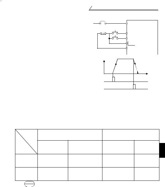
(2) 3 STF,STR,STOP
3 (STOP)
Pr.63 “- — -”STOP-SD
功能。
STF(STR)-SD
STR(STF)-SD ( )STOP Pr.60 Pr.62(
) STOP-SD
(1)3
JOG-SD STOPJOG
MRS-SD
|
NFB |
||
|
L1<L1>,L2<N>,L3 |
||
|
STF |
||
|
STR(Pr.63=“- — -” |
||
|
STOP |
||
|
SD |
|
ON |
||
|
ON |
||
3
|
PU |
|||||
|
Pr.79 “0”,“2”,“3” |
Pr.79 “0”,“1”,“4” |
||||
|
STF(STR)- |
|||||
|
SD OFF |
0Hz |
||||
|
0Hz |
1 |
||||
|
*1 |
|||||
|
Pr.10 “ |
Pr.10“ |
0.5Hz |
|||
|
” 0.5Hz |
” |
||||
|
Pr.10 “ |
Pr.10“ |
0.5Hz |
|||
|
” 0.5Hz |
” |
||||
|
*1. RESETSTOP 86 |
19

|
Pr.13 |
(*4) |
|||||
|
(*1) |
Pr.10 |
|||||
|
0.5Hz |
3Hz 0.5Hz |
0.5Hz |
3Hz |
|||
|
0.5s |
0.5s |
|||||
|
ON |
||||||
|
ON |
ON |
|||||
|
STF-SD |
Pr.11(*3) |
Pr.11(*3) |
||||
|
STR-SD |
||||||
|
(*2) |
||||||
|
· |
||||||
|
(*4) |
||||||
|
Pr.10 |
||||||
|
Pr.13 |
ON |
|||||
|
(*1) |
||||||
|
3Hz |
||||||
|
0.5Hz |
0.5Hz |
|||||
|
3Hz |
||||||
|
0.5s |
||||||
|
Pr.11 |
||||||
|
ON |
ON |
(*3) |
||||
|
STF-SD |
ON |
ON |
||||
STR-SD
*1.Pr.13“ ” 0.5Hz 0 60Hz
*2.
*3.Pr.11“ ” 0.5s 0 10s
*4. Pr.10“ ” 3Hz 0 120Hz 0.5Hz
*5.Pr.13“ ” Pr.11“ ” Pr.10“ ”
20
![]()
(2) 4,5,AU
DC4 20mA 4-5
DC4 20mA AU-SD AU Pr.60 Pr.63
|
AU-SD |
|||||||||||||
|
AU |
ON |
OFF |
|||||||||||
|
SD |
|||||||||||||
|
10 |
|||||||||||||
|
2 |
0 5V |
||||||||||||
|
4 20mA |
(0 10V) |
||||||||||||
|
5 |
|||||||||||||
|
4 |
|||||||||||||
|
DC4-20mA |
|||||||||||||
1.4.3 (REX,RH,RM,RL)
REX,RH,RM,RL-SD 15 * 7 STF(STR)-SD

 ·* Pr.63“STR ” “8” 15 (REX)
DC0 5V,0 10V,4 20mA
|
1 |
||||||||||||||||||||||||||
|
( ) |
2 |
5 |
10 |
|||||||||||||||||||||||
|
11 |
||||||||||||||||||||||||||
|
( ) |
6 |
9 |
12 |
|||||||||||||||||||||||
|
3 4 |
8 |
13 |
||||||||||||||||||||||||
|
( ) |
14 |
|||||||||||||||||||||||||
|
7 |
||||||||||||||||||||||||||
|
15 |
||||||||||||||||||||||||||
|
(Hz) |
||||||||||||||||||||||||||
|
ON |
ON |
ON |
ON |
RH |
ON |
ON |
ON |
ON |
||||||||||||||||||
|
ON |
ON |
ON |
ON |
RM |
ON |
ON |
ON |
ON |
||||||||||||||||||
|
ON |
ON |
ON |
RL |
ON |
ON |
ON |
ON |
|||||||||||||||||||
|
REX |
ON |
ON |
ON |
ON |
ON |
ON |
ON |
ON |
||
22

1.4.4 (AM)
AM-5 DC5VFR-PU04-CH AMPr.54“AM ”AM 30
AM 100ms
|
CPU |
AM |
AM |
||||||||||||||||||
|
5 |
5VDC |
||||
AM
设定输出满量程电压DC5V
Pr.55 Pr.56
AM C1
[ ]1. 90Hz AM-5 DC5V Pr.55 90Hz50Hz
2. 20A AM-5 DC5V Pr.56 20A
 ● 106
● 106
24

1.4.5 (SD,5,SE)
SD,5,SESD (STF,STR,RH,RM,RL)5 “AM”
SE (RUN)
1.4.6
|
+24V |
||||||||||||
|
STF,STR,RH,RM,RL |
||||||||||||
|
STF |
||||||||||||
|
SD |
||||||||||||
 1. PC
1. PC
16
2.SSR OFF 1
25

RL RM RH STR
1.5 RL RM RH STR
|
Pr.60 Pr.63 |
Pr.60“RL ” |
|
|
Pr.61“RM ” |
80 |
|
|
Pr.62“RH ” |
||
|
Pr.63“STR ” |
||
1.5.1 RL RM RH REX Pr.60 Pr.63 “0,1,2,8”RL RM RH Pr.60 Pr.63 “0,1,2”
· RL RM RH REX ON/OFF 15
22 ·
77
1.5.2 RT Pr.60 Pr.63 “3”
|
Pr.44“ 2 ” |
|||||||
|
Pr.45“ 2 ” |
|||||||
|
Pr.46“ 2 ” |
|||||||
|
Pr.47“ 2V/F ” |
STF(STR) |
||||||
|
, RT ON |
2 |
RT |
|||||
|
SD |
|||||||
1.5.3 AU Pr.60 Pr.63 “4”
DC4 20mA4-5 DC4 20mAAU
|
/ |
||||
|
AU |
AU-SD |
ON |
OFF |
|
|
SD |
||||
|
10 |
0 5V |
|||
|
2 |
4 20mA |
(0 10V) |
||
|
5 |
||||
|
4 |
||||
|
DC4-20mA |
||||

26

RL RM RH STR
1.5.4 STOP Pr.60 Pr.63 “5”
1.5.5 MRS Pr.60 Pr.63 “6”
MRS-SDMRS-SD 10ms MRS
|
0.5Hz |
Pr.13 |
|
|
» « |
||
|
MRS -SD |
ON |
|
STF-SD |
ON |
||||
|
(STR) |
|||||
(3)
3Hz MRS
1.5.6 Pr.60 Pr.63 “7”
1
27

RL RM RH STR
1.5.7 Pr.60 Pr.63 “9”
(1)
|
JOG-SD |
Pr.15 |
||||||||||||||||||||
|
STF |
|||||||||||||||||||||
|
STR-SD |
0.5Hz |
3Hz |
|||||||||||||||||||
|
Pr.15 |
|||||||||||||||||||||
|
5Hz 0 120Hz |
|||||||||||||||||||||
|
Pr.16 0.5s |
|||||||||||||||||||||
|
0 999s |
|||||||||||||||||||||
|
JOG -SD |
|||||||||||||||||||||
|
ON |
ON |
||||||||||||||||||||
|
STF-SD |
ON |
||||||||||||||||||||
|
STR-SD |
ON |
||||||||||||||||||||
1.5.8 Pr.60 Pr.63 “10”
(Cold)RES-SD 0.1
RES-SD 1s → Pr.75 “1” “15”
86
|
(Hz) |
|||
|
ON |
ON |
||
|
RES -SD ON |
|||
|
STF(STR)-SD |
|||
|
T |
|||
|
T: |
|||
|
28 |

RS-485
1.5.9 PID Pr.60 Pr.63 “14”
PID X14 ON OFF93
Pr.88“PID ” Pr.89“PID ” Pr.90“PID ” Pr.91“ ” Pr.92“ ” Pr.93“PU PID ” Pr.94“PID ” 93
1.5.10 PU / Pr.60 Pr.63 “16”
Pr.79“ ” “8 X16 ON X16 OFF
PU 90
Pr.79“ ” 90
1.6 RS-485
RS-485 A
|
A |
||
|
SG |
SDA |
|
|
P5S |
RDB |
|
|
RDA |
SG |
|
|
SDB |
P5S |
|
|
A |
1 |
1.
2. (P5S) RS-485
3. 109
1.6.1 FR-PU04-CH
RS-485 FR-CB2□□
RESETSTOP
 126
126
29

RS-485
1.6.2 RS-485
RS-485 RS-485
109
· EIA-485(RS-485) ·
· MAX 19200bps · 500m
RS-485 109
(1) 1 1
|
0 |
0 |
|||||||||
|
RS-232C |
||||||||||
|
RS-232C |
||||||||||
|
RS-485 |
15m |
RS-485 |
||||||||
|
RS-485 |
||||||||||
|
RS-232C RS-485 |
||||||||||
|
· |
||||||||||
|
RJ-45 |
RJ-45 |
|||||||||
|
10BASE-T |
10BASE-T |
|||||||||
|
● — |
||||||||||
|
RS-232C RS232CÙRS485 |
||||||||||
|
04 4 |
||||||||||
|
FA-T-RS40□(*) |
*1 1RS-232C RS-485 10BASE-T+RJ-45
04 4
|
10BASE-T |
SGLPEV-T 0.5mm×4P |
||
|
2.8 P5S |
|||
30

“ ”
|
2.1 |
…………………….. |
36 |
|
2.2 |
……………….. |
45 |
|
2.3 |
………………………. |
46 |
|
2.4 |
………………………. |
68 |
|
2.5 |
………………………. |
70 |
|
2.6 |
………………………….. |
72 |
|
2.7 |
………………………… |
74 |
|
2.8 |
……………………………… |
77 |
|
2.9 |
………………………. |
80 |
|
2.10 |
………………………. |
82 |
|
2.11 |
…………………………….. |
100 |
|
2.12 |
…………………………….. |
102 |
|
2.13 |
…………………………….. |
106 |
|
2.14 |
…………………………….. |
108 |
|
2.15 |
…………………………….. |
109 |
|
2.16 |
(FR-PU04-CH) …………….. |
126 |
RL,RM,RH,MRSRUN A,B,C

FR-PU04-CHFR-S500 FR-PU04-CH
35

2.1
|
Pr.77“ ” “0( )” |
|||||||||||
|
( , Pr.53, Pr.70, Pr.72 PU ) |
|||||||||||
|
6 /5 |
|||||||||||
|
0 |
0 15 |
0.1 |
/4 |
46 |
|||||||
|
( 1) |
|||||||||||
|
1 |
0 120Hz |
0.1Hz |
50Hz |
47 |
|||||||
|
2 |
0 120Hz |
0.1Hz |
0Hz |
47 |
|||||||
|
3 |
0 120Hz |
0.1Hz |
50Hz |
48 |
|||||||
|
4 |
3 |
0 120Hz |
0.1Hz |
50Hz |
49 |
||||||
|
5 |
3 |
0 120Hz |
0.1Hz |
30Hz |
49 |
||||||
|
6 |
3 |
0 120Hz |
0.1Hz |
10Hz |
49 |
||||||
|
7 |
0 999s |
0.1s |
5s |
50 |
|||||||
|
8 |
0 999s |
0.1s |
5s |
50 |
|||||||
|
9 |
0 50A |
0.1A |
52 |
||||||||
|
30 |
0 1 |
1 |
0 |
61 |
|||||||
|
79 |
0 4 7 8 |
1 |
0 |
90 |
1. FR-S540E-1.5K,2.2K-CH 5 FR-S540E-3.7K-CH 4
Pr.30“ ” “1”
Pr.30
|
0 9 |
||||||||
|
10 |
0 120Hz |
0.1Hz |
3Hz |
54 |
||||
|
11 |
0 10s |
0.1s |
0.5s |
54 |
||||
|
12 |
0 15 |
0.1 |
6 |
54 |
||||
|
13 |
0 60Hz |
0.1Hz |
0.5Hz |
55 |
||||
|
0: |
||||||||
|
14 |
1: |
1 |
0 |
56 |
||||
|
2: |
||||||||
|
3: |
||||||||
|
15 |
0 120Hz |
0.1Hz |
5Hz |
57 |
||||
|
16 |
0 999s |
0.1s |
0.5s |
57 |
||||
|
17 |
RUN |
0: 1: |
1 |
0 |
57 |
|||
36
The electronic thermal relay function does not guarantee protection of the motor
from overheating.
Do not use a magnetic contactor on the inverter input for frequent starting/stopping
of the inverter.
Use a noise filter to reduce the effect of electromagnetic interference. Otherwise
nearby electronic equipment may be affected.
Take measures to suppress harmonics. Otherwise power supply harmonics from
the inverter may heat/damage the power capacitor and generator.
When a 400V class motor is inverter-driven, please use an insulation-enhanced
motor or measures taken to suppress surge voltages. Surge voltages attributable to
the wiring constants may occur at the motor terminals, deteriorating the insulation of
the motor.
When parameter clear or all clear is performed, reset the required parameters
before starting operations. Each parameter returns to the factory setting.
The inverter can be easily set for high-speed operation. Before changing its
setting, fully examine the performances of the motor and machine.
In addition to the inverter’s holding function, install a holding device to ensure safety.
Before running an inverter which had been stored for a long period, always
perform inspection and test operation.
(5) Emergency stop
Provide a safety backup such as an emergency brake which will prevent the
machine and equipment from hazardous conditions if the inverter fails.
When the breaker on the inverter primary side trips, check for the wiring fault (short
circuit), damage to internal parts of the inverter, etc. Identify the cause of the trip,
then remove the cause and power on the breaker.
When any protective function is activated, take the appropriate corrective action,
then reset the inverter, and resume operation.
(6) Maintenance, inspection and parts replacement
Do not carry out a megger (insulation resistance) test on the control circuit of the
inverter.
(7) Disposing of the inverter
Treat as industrial waste.
(8) General instructions
Many of the diagrams and drawings in this instruction manual (detailed) show the inverter
without a cover, or partially open. Never operate the inverter in this manner. Always replace
the cover and follow this instruction manual (detailed) when operating the inverter.
CAUTION
CAUTION
CAUTION
CAUTION
A-4
2
●
●
●
3
● ● ● ●
4 (1)
● ● ● ● ● ●
● ● ● ●
|
10°C 50°C |
|||
|
90 RH |
|||
|
20°C 65°C* |
|||
|
1000m 5.9m/s2 JIS C 60068-2-6 |
|||
|
* |
(2)
● ( FR-BIF) ● ( U,V,W)
(3)
●
●400V 1.5K 3.7K GD2 20Hz 30HzPr.72″PWM » 6kHz
A-2
|
1. |
1 |
|
|
1.1 |
…………………………………… |
2 |
|
1.1.1 ………………………………………….. |
2 |
|
|
1.1.2 …………………………………. |
3 |
|
|
1.2 |
…………………………………… |
5 |
|
1.2.1 ………………………………………… |
5 |
|
|
1.2.2 ……………………………. |
6 |
|
|
1.2.3 …………………………………….. |
7 |
|
|
1.2.4 ……………………………………………. |
8 |
|
|
1.2.5 ……………………………… |
9 |
|
|
1.2.6 (MC) …………………………….. |
11 |
|
|
1.2.7 …………………………….. |
12 |
|
|
1.2.8 ………………………………. |
12 |
|
|
1.2.9 ………………………………………………. |
13 |
|
|
1.2.10 ………………………………………….. |
14 |
|
|
1.2.11 400V ……………………………….. |
14 |
|
|
1.3 |
………………………………… |
15 |
|
1.3.1 ……………………………………….. |
15 |
|
|
1.3.2 ……………………………………. |
15 |
|
|
1.3.3 ……………………………………….. |
16 |
|
|
1.4 |
…………………………………………….. |
18 |
|
1.4.1 STF,STR,STOP ……………………. |
18 |
|
|
1.4.2 (10,2,5,4,AU) ……………… |
21 |
|
|
1.4.3 (REX,RH,RM,RL) …………………………… |
22 |
|
|
1.4.4 (AM) ………………………………….. |
24 |
|
|
1.4.5 (SD,5,SE) ………………………….. |
25 |
|
|
1.4.6 ………………………………… |
25 |
|
|
1.5 RL RM RH STR ……………. |
26 |
|
|
1.5.1 RL RM RH REX Pr.60 Pr.63 “0,1,2,8” |
||
|
RL RM RH Pr.60 Pr.63 “0,1,2” …. 26 |
||
|
1.5.2 RT Pr.60 Pr.63 “3” ………….. |
26 |
|
|
1.5.3 AU Pr.60 Pr.63 “4” ………… |
26 |
|
|
1.5.4 STOP Pr.60 Pr.63 “5” …….. |
27 |
|
|
1.5.5 MRS Pr.60 Pr.63 “6” …………… |
27 |
|
|
1.5.6 Pr.60 Pr.63 “7” ……………… |
27 |
|
|
1.5.7 Pr.60 Pr.63 “9” ………….. |
28 |
|
|
1.5.8 Pr.60 Pr.63 “10” ……………………. |
28 |
|
|
1.5.9 PID Pr.60 Pr.63 “14” ……………… |
29 |
|
|
1.5.10 PU / Pr.60 Pr.63 “16” …………. |
29 |
I
|
1.6 |
RS-485 |
……………………………………… |
29 |
|||||||||||
|
1.6.1 FR-PU04-CH …………………………. |
29 |
|||||||||||||
|
1.6.2 |
RS-485 …………………… |
30 |
||||||||||||
|
1.7 |
……………………………………… |
33 |
||||||||||||
|
2. |
35 |
|||||||||||||
|
2.1 |
……………………………………. |
36 |
||||||||||||
|
2.2 |
………………………………. |
45 |
||||||||||||
|
2.3 |
……………………………………… |
46 |
||||||||||||
|
2.3.1 |
46 |
|||||||||||||
|
2.3.2 |
47 |
|||||||||||||
|
2.3.3 |
………………. |
48 |
||||||||||||
|
2.3.4 |
…. 49 |
|||||||||||||
|
2.3.5 |
………………… |
50 |
||||||||||||
|
2.3.6 ( |
, |
, |
) ……………………… |
52 |
||||||||||
|
2.3.7 |
…………………………… |
54 |
||||||||||||
|
2.3.8 |
……………………………………. |
55 |
||||||||||||
|
2.3.9 |
………………………………… |
56 |
||||||||||||
|
2.3.10 |
………………………………. |
57 |
||||||||||||
|
2.3.11 RUN |
………………………… |
57 |
||||||||||||
|
2.3.12 |
…………………… |
58 |
||||||||||||
|
2.3.13 |
………………………….. |
59 |
||||||||||||
|
2.3.14 |
…………………………………. |
61 |
||||||||||||
|
2.3.15 ……………………………. |
61 |
|||||||||||||
|
2.3.16 |
……………………………. |
62 |
||||||||||||
|
2.3.17 |
……………………………….. |
63 |
||||||||||||
|
2.3.18 |
64 |
|||||||||||||
|
2.3.19 |
………………………….. |
68 |
||||||||||||
|
2.4 |
……………………………………… |
68 |
||||||||||||
|
2.4.1 |
…………………………….. |
68 |
||||||||||||
|
2.4.2 |
………………………….. |
69 |
||||||||||||
|
2.5 |
……………………………………… |
70 |
||||||||||||
|
2.5.1 |
………………………… |
70 |
||||||||||||
|
2.5.2 |
……………………………… |
71 |
||||||||||||
|
2.6 |
…………………………………………. |
72 |
||||||||||||
|
2.6.1 |
……………………………….. |
72 |
||||||||||||
|
2.6.2 |
………………………………… |
73 |
||||||||||||
|
2.6.3 |
……………………………….. |
74 |
||||||||||||
|
2.7 |
……………………………………….. |
74 |
||||||||||||
|
2.7.1 |
…………………………. |
74 |
||||||||||||
|
2.8 |
…………………………………………….. |
77 |
II
|
2.8.1 |
…………………………….. |
77 |
||||||||||||||||||||||||||||||||
|
………………………………………2.9 |
80 |
|||||||||||||||||||||||||||||||||
|
2.9.1 |
80 |
|||||||||||||||||||||||||||||||||
|
2.9.2 |
81 |
|||||||||||||||||||||||||||||||||
|
………………………… |
||||||||||||||||||||||||||||||||||
|
……………………………………..2.10 |
82 |
|||||||||||||||||||||||||||||||||
|
2.10.1 |
82 |
|||||||||||||||||||||||||||||||||
|
2.10.2 PWM |
84 |
|||||||||||||||||||||||||||||||||
|
2.10.3 |
85 |
|||||||||||||||||||||||||||||||||
|
2.10.4 |
86 |
|||||||||||||||||||||||||||||||||
|
2.10.5 /PU |
86 |
|||||||||||||||||||||||||||||||||
|
2.10.6 |
…………………………… |
88 |
||||||||||||||||||||||||||||||||
|
2.10.7 |
89 |
|||||||||||||||||||||||||||||||||
|
2.10.8 |
89 |
|||||||||||||||||||||||||||||||||
|
2.10.9 |
90 |
|||||||||||||||||||||||||||||||||
|
2.10.10 PID |
93 |
|||||||||||||||||||||||||||||||||
|
2.11 …………………………………………… |
100 |
|||||||||||||||||||||||||||||||||
|
2.11.1 |
100 |
|||||||||||||||||||||||||||||||||
|
2.11.2 |
101 |
|||||||||||||||||||||||||||||||||
|
2.11.3 |
101 |
|||||||||||||||||||||||||||||||||
|
2.12 …………………………………………… |
102 |
|||||||||||||||||||||||||||||||||
|
2.12.1 |
102 |
|||||||||||||||||||||||||||||||||
|
2.12.2 |
, |
, |
103 |
|||||||||||||||||||||||||||||||
|
……………………………………………2.13 |
106 |
|||||||||||||||||||||||||||||||||
|
2.13.1 |
…………………… |
106 |
||||||||||||||||||||||||||||||||
|
2.14 …………………………………………… |
108 |
|||||||||||||||||||||||||||||||||
|
2.14.1 ………………………………….. |
108 |
|||||||||||||||||||||||||||||||||
|
2.14.2 |
……………………………… |
108 |
||||||||||||||||||||||||||||||||
|
2.15 …………………………………………… |
109 |
|||||||||||||||||||||||||||||||||
|
2.15.1 |
, |
……………………… |
111 |
|||||||||||||||||||||||||||||||
|
2.15.2 |
……………………… |
123 |
||||||||||||||||||||||||||||||||
|
2.15.3 |
…………………………… |
124 |
||||||||||||||||||||||||||||||||
|
2.15.4 E2PROM |
………………………… |
125 |
||||||||||||||||||||||||||||||||
|
2.16 (FR-PU04-CH) …………………………… |
126 |
|||||||||||||||||||||||||||||||||
|
2.16.1 |
……………………….. |
126 |
||||||||||||||||||||||||||||||||
|
2.16.2 |
………………………………. |
126 |
||||||||||||||||||||||||||||||||
|
2.16.3 PU |
………………………………. |
127 |
||||||||||||||||||||||||||||||||
|
2.16.4 PU |
……………………….. |
127 |
||||||||||||||||||||||||||||||||
|
2.16.5 PU /PU |
…………………… |
128 |
||||||||||||||||||||||||||||||||
|
3. |
129 |
|||||||||||||||||||||||||||||||||
III
![]()
1.1
1.1.1
●3 400V
|
NFB |
MC |
||||||||||||
|
L1 |
|||||||||||||
|
U |
|||||||||||||
|
IM |
|||||||||||||
|
3 |
L2 |
V |
|||||||||||
|
L3 |
W |
||||||||||||
|
24V |
|||||||||||||
|
P1 |
|||||||||||||
|
PC |
|||||||||||||
|
( ) |
|||||||||||||
|
PC-SD |
(FR-BEL ) |
||||||||||||
|
+ |
|||||||||||||
|
— |
FR-BEL |
||||||||||||
|
STF |
*4 A |
||||||||||||
|
STR *3 |
*4 B |
||||||||||||
|
RH |
*3 |
*4 C |
|||||||||||
|
RM |
*3 |
||||||||||||
|
RL |
*3 |
*4 RUN |
|||||||||||
|
SD |
|||||||||||||
|
SE |
|||||||||||||
|
SINK |
|||||||||||||
|
( ) |
*1 |
||||||||||||
|
( ) |
SOURCE |
||||||||||||
|
3 |
10(+5V) |
||||||||||||
|
1/2W1kΩ*2 |
2 |
2 |
DC0 5V |
||||||||||
|
DC0 10V |
|||||||||||||
|
1 |
5( ) |
AM |
(+) |
||||||||||
|
(-) |
|||||||||||||
|
(DC0 5V) |
|||||||||||||
|
DC4 20mA(+) |
4(DC4 20mA) |
5 |
(-) |
||||||||||
|
RS-485 |
|||||||||||||
|
Pr.60 Pr.63 |
|||||||||||||
|
«4» |
|||||||||||||
|
RH,RM,RL,STR AU |
|||||||||||||
|
2mm2 |
|||||||||||||
|
AU ON |
|||||||||||||
*1 16
*2 2W1KΩ
*3 Pr.60 Pr.63 80
RES,RL,RM,RH,RT,AU,STOP,MRS,OH,REX,JOG,X14,X16,(STR)
*4 Pr.64 Pr.65 81
RUN,SU,OL,FU,RY,Y12,Y13,FDN,FUP,RL,Y93,Y95,LF,ABC
● 10cm
2
|
DC0 5V (0 10V) , 5V(10V) |
|||||||||
|
2 |
|||||||||
|
( ) |
5V/10V Pr.73“0 5V 0 10V ” |
||||||||
|
10kΩ 20V |
|||||||||
|
DC4 20mA 4mA 0Hz 20mA 50Hz |
|||||||||
|
30mA 250Ω |
|||||||||
|
4 |
AU ON |
||||||||
|
( ) |
|||||||||
|
AU ON |
|||||||||
|
AU Pr.60 Pr.63( |
|||||||||
|
5 |
( 2,4) “AM” |
||||||||
|
(*6) |
|||||||||
|
A |
AC230V 0.3A |
DC30V |
|||||||
|
B |
0.3A B-C (A-C |
||||||||
|
C |
) B-C (A-C |
||||||||
|
) *5 |
(Pr.64 Pr.65 |
||||||||
|
0.5Hz |
(*4) |
||||||||
|
(*2) |
|||||||||
|
DC24V 0.1A ON |
|||||||||
|
3.4V |
|||||||||
|
SE |
RUN (*6) |
||||||||
|
AM |
1mA |
||||||||
|
DC 0 5V |
|||||||||
|
RS-485 |
FR-CB201 205 FR- |
||||||||
|
── |
PU04-CH RS-485 RS-485 |
||||||||
|
30 |
|||||||||
*1. SD PC SD PC16
*2. ON OFF
*3.RL,RM,RH,RT,AU,STOP,MRS,OH,REX,JOG,RES,X14,X16,(STR) 80 *4.RUN,SU,OL,FU,RY,Y12,Y13,FDN,FUP,RL,Y93,Y95,LF,ABC 81
*5. A,B,C DC30V 0.3A *6. SD SE 5
4
1.2
1.2.1
|
3 400V |
||||||||||
|
●FR-S540E-0.4K,0.75K,1.5K,2.2K, |
||||||||||
|
3.7K-CH |
||||||||||
|
— + |
||||||||||
|
P1 |
||||||||||
|
L1 L2 |
L3 |
U |
V |
W |
||||||
|
IM |
||||||||||
|
200V |
||||||||||
|
●FR-S520SE-0.2K,0.4K,0.75K-CH |
●FR-S520SE-1.5K-CH |
|||||||||
|
— |
P1 |
+ |
— |
+ |
||||||
|
L1 |
N |
U |
V |
W |
P1 |
|||||
|
L1 N |
U |
V |
W |
|||||||
|
IM |
|
IM |
||||
● L1,L2,L3 U,V,W, ( ) ● U,V,W
1
5
1.2.2
20
3 400V
|
PVC |
|||||||||||
|
mm2 |
AWG |
mm2 |
|||||||||
|
L1,L2, |
L1,L2, |
L1,L2, |
L1,L2, |
||||||||
|
N·m |
U,V,W |
U,V,W |
U,V,W |
U,V,W |
|||||||
|
L3, |
L3, |
L3, |
L3, |
||||||||
|
FR-S540E-0.4K |
M4 |
1.5 |
2-4 |
2-4 |
2 |
2 |
14 |
14 |
2.5 |
2.5 |
|
|
3.7K-CH |
|||||||||||
|
200V |
|||||||||||
|
PVC |
|||||||||||
|
mm2 |
AWG |
mm2 |
|||||||||
|
N·m |
|||||||||||
|
L1,N |
U,V,W |
L1,N |
U,V,W |
L1,N |
U,V,W |
L1,N |
U,V,W |
||||
|
FR-S520SE-0.2K |
M3.5 |
1.2 |
2-3.5 |
2-3.5 |
2 |
2 |
14 |
14 |
2.5 |
2.5 |
|
|
0.75K-CH |
|||||||||||
|
FR-S520SE-1.5K |
M4 |
1.5 |
2-4 |
2-4 |
2 |
2 |
14 |
14 |
2.5 |
2.5 |
|
|
-CH |
|||||||||||
●
100m FR-S540E-0.4K-CH:50m
·0.2K 30m 1kHz
·FR-S540E-0.4K,0.75K-CH 30m 1kHz · Pr.98“ ” 30
101
6
1.2.3
(U,V,W),
持变频器清洁。
2%
2
变频器输入/ AM FR-BIF FR-BSF01FR-BLF
FR-BIFFR-BIF T
10
1
7
(3)
, PWM
|
· · |
CV |
3 |
||||||||||||||||||||||||||||||||||||||||||||||||||||||||||||||
|
: |
||||||||||||||||||||||||||||||||||||||||||||||||||||||||||||||||
|
1km |
||||||||||||||||||||||||||||||||||||||||||||||||||||||||||||||||
|
I n 10×(Ig1 Ign Ig2 Igm) |
||||||||||||||||||||||||||||||||||||||||||||||||||||||||||||||||
|
3 3 400V60Hz 400V60Hz |
||||||||||||||||||||||||||||||||||||||||||||||||||||||||||||||||
|
· |
||||||||||||||||||||||||||||||||||||||||||||||||||||||||||||||||
|
120 |
2.0 |
|||||||||||||||||||||||||||||||||||||||||||||||||||||||||||||||
|
: |
100 |
0.71.0 |
||||||||||||||||||||||||||||||||||||||||||||||||||||||||||||||
|
I n 10×{Ig1 Ign 3×(Ig2 Igm)} |
80 |
|||||||||||||||||||||||||||||||||||||||||||||||||||||||||||||||
|
Ig1,Ig2 |
60 |
0.5 |
||||||||||||||||||||||||||||||||||||||||||||||||||||||||||||||
|
40 |
0.3 |
|||||||||||||||||||||||||||||||||||||||||||||||||||||||||||||||
|
Ign* |
(mA) 20 |
(mA)0.2 |
||||||||||||||||||||||||||||||||||||||||||||||||||||||||||||||
|
0 |
0.1 |
|||||||||||||||||||||||||||||||||||||||||||||||||||||||||||||||
|
2 3.5 |
8 142238 80150 |
1.5 3.7 7.5 15223755 |
||||||||||||||||||||||||||||||||||||||||||||||||||||||||||||||
|
5.5 |
30 60100 |
2.2 |
5.5 1118.53045 |
|||||||||||||||||||||||||||||||||||||||||||||||||||||||||||||
|
(mm2) |
(kW) |
|||||||||||||||||||||||||||||||||||||||||||||||||||||||||||||||
|
Igm |
1 |
|||||||||||||||||||||||||||||||||||||||||||||||||||||||||||||||
|
3 |
||||||||||||||||||||||||||||||||||||||||||||||||||||||||||||||||
|
5.5mm2x5m 5.5mm2x70m |
||||||||||||||||||||||||||||||||||||||||||||||||||||||||||||||||
|
NV |
||||||||||||||||||||||||||||||||||||||||||||||||||||||||||||||||
|
3 |
||||||||||||||||||||||||||||||||||||||||||||||||||||||||||||||||
|
IM 400V2.2kW |
||||||||||||||||||||||||||||||||||||||||||||||||||||||||||||||||
|
Ig1 Ign |
Ig2 |
Igm |
||||||||||||||||||||||||||||||||||||||||||||||||||||||||||||||
|
· |
||||||||||||||||||||||||||||||||||||||||||||||||||||||||||||||||
|
Ig1(mA) |
1 |
×66× |
5m |
0.11 |
||||||||||||||||||||||||||||||||||||||||||||||||||||||||||||
|
3 |
1000m |
|||||||||||||||||||||||||||||||||||||||||||||||||||||||||||||||
|
Ign(mA) |
0 |
|||||||||||||||||||||||||||||||||||||||||||||||||||||||||||||||
|
Ig2(mA) |
1 |
×66× |
70m |
1.54 |
||||||||||||||||||||||||||||||||||||||||||||||||||||||||||||
|
3 |
1000m |
|||||||||||||||||||||||||||||||||||||||||||||||||||||||||||||||
|
Igm(mA) |
0.36 |
|||||||||||||||||||||||||||||||||||||||||||||||||||||||||||||||
|
(mA) |
2.01 |
5.81 |
||||||||||||||||||||||||||||||||||||||||||||||||||||||||||||||
|
(mA) |
30 |
100 |
||||||||||||||||||||||||||||||||||||||||||||||||||||||||||||||
|
( Ig × 10) |
||||||||||||||||||||||||||||||||||||||||||||||||||||||||||||||||
|
* |
·NV
· (JIS NEC
250 ,IEC536 1 ) ·
· ……BV-C1 BC-V NVB NV-L NV-G2N NV-G3NA
NV-2F NV-ZHA NV-H — NV
· ……NV-C·NV-S·MN NV30-FA NV50FA BV-C2 NF-Z NV-ZHA NV-H
10
1.2.10
, ,, (RF)
· RF :
|
RF |
||
|
40 50 ( 3kHz ) |
( kHz MHz ) |
|
|
, |
, , |
|
|
, |
||
|
( ) |
||
: ,
1.2.11 400V
PWM 400V400V :
● :
(1)
400V , ,
1)“400V ”
2)“ ”
↔ 40m Pr.70“Soft-PWM ”Pr.70 84
(2)
2 , (FR-ASF-H)
14
(2) 3 STF,STR,STOP
3 (STOP)
Pr.63 “- — -”STOP-SD
功能。
STF(STR)-SD
STR(STF)-SD ( )STOP Pr.60 Pr.62(
) STOP-SD
(1)3
JOG-SD STOPJOG
MRS-SD
|
NFB |
||
|
L1<L1>,L2<N>,L3 |
||
|
STF |
||
|
STR(Pr.63=“- — -” |
||
|
STOP |
||
|
SD |
|
ON |
||
|
ON |
||
3
|
PU |
|||||
|
Pr.79 “0”,“2”,“3” |
Pr.79 “0”,“1”,“4” |
||||
|
STF(STR)- |
|||||
|
SD OFF |
0Hz |
||||
|
0Hz |
1 |
||||
|
*1 |
|||||
|
Pr.10 “ |
Pr.10“ |
0.5Hz |
|||
|
” 0.5Hz |
” |
||||
|
Pr.10 “ |
Pr.10“ |
0.5Hz |
|||
|
” 0.5Hz |
” |
||||
|
*1. RESETSTOP 86 |
19
|
Pr.13 |
(*4) |
|||||
|
(*1) |
Pr.10 |
|||||
|
0.5Hz |
3Hz 0.5Hz |
0.5Hz |
3Hz |
|||
|
0.5s |
0.5s |
|||||
|
ON |
||||||
|
ON |
ON |
|||||
|
STF-SD |
Pr.11(*3) |
Pr.11(*3) |
||||
|
STR-SD |
||||||
|
(*2) |
||||||
|
· |
||||||
|
(*4) |
||||||
|
Pr.10 |
||||||
|
Pr.13 |
ON |
|||||
|
(*1) |
||||||
|
3Hz |
||||||
|
0.5Hz |
0.5Hz |
|||||
|
3Hz |
||||||
|
0.5s |
||||||
|
Pr.11 |
||||||
|
ON |
ON |
(*3) |
||||
|
STF-SD |
ON |
ON |
||||
STR-SD
*1.Pr.13“ ” 0.5Hz 0 60Hz
*2.
*3.Pr.11“ ” 0.5s 0 10s
*4. Pr.10“ ” 3Hz 0 120Hz 0.5Hz
*5.Pr.13“ ” Pr.11“ ” Pr.10“ ”
20
![]()
(2) 4,5,AU
DC4 20mA 4-5
DC4 20mA AU-SD AU Pr.60 Pr.63
|
AU-SD |
|||||||||||||
|
AU |
ON |
OFF |
|||||||||||
|
SD |
|||||||||||||
|
10 |
|||||||||||||
|
2 |
0 5V |
||||||||||||
|
4 20mA |
(0 10V) |
||||||||||||
|
5 |
|||||||||||||
|
4 |
|||||||||||||
|
DC4-20mA |
|||||||||||||
1.4.3 (REX,RH,RM,RL)
REX,RH,RM,RL-SD 15 * 7 STF(STR)-SD
·* Pr.63“STR ” “8” 15 (REX)
DC0 5V,0 10V,4 20mA
|
1 |
||||||||||||||||||||||||||
|
( ) |
2 |
5 |
10 |
|||||||||||||||||||||||
|
11 |
||||||||||||||||||||||||||
|
( ) |
6 |
9 |
12 |
|||||||||||||||||||||||
|
3 4 |
8 |
13 |
||||||||||||||||||||||||
|
( ) |
14 |
|||||||||||||||||||||||||
|
7 |
||||||||||||||||||||||||||
|
15 |
||||||||||||||||||||||||||
|
(Hz) |
||||||||||||||||||||||||||
|
ON |
ON |
ON |
ON |
RH |
ON |
ON |
ON |
ON |
||||||||||||||||||
|
ON |
ON |
ON |
ON |
RM |
ON |
ON |
ON |
ON |
||||||||||||||||||
|
ON |
ON |
ON |
RL |
ON |
ON |
ON |
ON |
|||||||||||||||||||
|
REX |
ON |
ON |
ON |
ON |
ON |
ON |
ON |
ON |
||
22
1.4.4 (AM)
AM-5 DC5VFR-PU04-CH AMPr.54“AM ”AM 30
AM 100ms
|
CPU |
AM |
AM |
||||||||||||||||||
|
5 |
5VDC |
||||
AM
设定输出满量程电压DC5V
Pr.55 Pr.56
AM C1
[ ]1. 90Hz AM-5 DC5V Pr.55 90Hz50Hz
2. 20A AM-5 DC5V Pr.56 20A
● 106
24
1.4.5 (SD,5,SE)
SD,5,SESD (STF,STR,RH,RM,RL)5 “AM”
SE (RUN)
1.4.6
|
+24V |
||||||||||||
|
STF,STR,RH,RM,RL |
||||||||||||
|
STF |
||||||||||||
|
SD |
||||||||||||
1. PC
16
2.SSR OFF 1
25
RL RM RH STR
1.5 RL RM RH STR
|
Pr.60 Pr.63 |
Pr.60“RL ” |
|
|
Pr.61“RM ” |
80 |
|
|
Pr.62“RH ” |
||
|
Pr.63“STR ” |
||
1.5.1 RL RM RH REX Pr.60 Pr.63 “0,1,2,8”RL RM RH Pr.60 Pr.63 “0,1,2”
· RL RM RH REX ON/OFF 15
22 ·
77
1.5.2 RT Pr.60 Pr.63 “3”
|
Pr.44“ 2 ” |
|||||||
|
Pr.45“ 2 ” |
|||||||
|
Pr.46“ 2 ” |
|||||||
|
Pr.47“ 2V/F ” |
STF(STR) |
||||||
|
, RT ON |
2 |
RT |
|||||
|
SD |
|||||||
1.5.3 AU Pr.60 Pr.63 “4”
DC4 20mA4-5 DC4 20mAAU
|
/ |
||||
|
AU |
AU-SD |
ON |
OFF |
|
|
SD |
||||
|
10 |
0 5V |
|||
|
2 |
4 20mA |
(0 10V) |
||
|
5 |
||||
|
4 |
||||
|
DC4-20mA |
||||
26
RL RM RH STR
1.5.4 STOP Pr.60 Pr.63 “5”
1.5.5 MRS Pr.60 Pr.63 “6”
MRS-SDMRS-SD 10ms MRS
|
0.5Hz |
Pr.13 |
|
|
» « |
||
|
MRS -SD |
ON |
|
STF-SD |
ON |
||||
|
(STR) |
|||||
(3)
3Hz MRS
1.5.6 Pr.60 Pr.63 “7”
1
27
RL RM RH STR
1.5.7 Pr.60 Pr.63 “9”
(1)
|
JOG-SD |
Pr.15 |
||||||||||||||||||||
|
STF |
|||||||||||||||||||||
|
STR-SD |
0.5Hz |
3Hz |
|||||||||||||||||||
|
Pr.15 |
|||||||||||||||||||||
|
5Hz 0 120Hz |
|||||||||||||||||||||
|
Pr.16 0.5s |
|||||||||||||||||||||
|
0 999s |
|||||||||||||||||||||
|
JOG -SD |
|||||||||||||||||||||
|
ON |
ON |
||||||||||||||||||||
|
STF-SD |
ON |
||||||||||||||||||||
|
STR-SD |
ON |
||||||||||||||||||||
1.5.8 Pr.60 Pr.63 “10”
(Cold)RES-SD 0.1
RES-SD 1s → Pr.75 “1” “15”
86
|
(Hz) |
|||
|
ON |
ON |
||
|
RES -SD ON |
|||
|
STF(STR)-SD |
|||
|
T |
|||
|
T: |
|||
|
28 |
RS-485
1.5.9 PID Pr.60 Pr.63 “14”
PID X14 ON OFF93
Pr.88“PID ” Pr.89“PID ” Pr.90“PID ” Pr.91“ ” Pr.92“ ” Pr.93“PU PID ” Pr.94“PID ” 93
1.5.10 PU / Pr.60 Pr.63 “16”
Pr.79“ ” “8 X16 ON X16 OFF
PU 90
Pr.79“ ” 90
1.6 RS-485
RS-485 A
|
A |
||
|
SG |
SDA |
|
|
P5S |
RDB |
|
|
RDA |
SG |
|
|
SDB |
P5S |
|
|
A |
1 |
1.
2. (P5S) RS-485
3. 109
1.6.1 FR-PU04-CH
RS-485 FR-CB2□□
RESETSTOP
126
29
RS-485
1.6.2 RS-485
RS-485 RS-485
109
· EIA-485(RS-485) ·
· MAX 19200bps · 500m
RS-485 109
(1) 1 1
|
0 |
0 |
|||||||||
|
RS-232C |
||||||||||
|
RS-232C |
||||||||||
|
RS-485 |
15m |
RS-485 |
||||||||
|
RS-485 |
||||||||||
|
RS-232C RS-485 |
||||||||||
|
· |
||||||||||
|
RJ-45 |
RJ-45 |
|||||||||
|
10BASE-T |
10BASE-T |
|||||||||
|
● — |
||||||||||
|
RS-232C RS232CÙRS485 |
||||||||||
|
04 4 |
||||||||||
|
FA-T-RS40□(*) |
*1 1RS-232C RS-485 10BASE-T+RJ-45
04 4
|
10BASE-T |
SGLPEV-T 0.5mm×4P |
||
|
2.8 P5S |
|||
30
“ ”
|
2.1 |
…………………….. |
36 |
|
2.2 |
……………….. |
45 |
|
2.3 |
………………………. |
46 |
|
2.4 |
………………………. |
68 |
|
2.5 |
………………………. |
70 |
|
2.6 |
………………………….. |
72 |
|
2.7 |
………………………… |
74 |
|
2.8 |
……………………………… |
77 |
|
2.9 |
………………………. |
80 |
|
2.10 |
………………………. |
82 |
|
2.11 |
…………………………….. |
100 |
|
2.12 |
…………………………….. |
102 |
|
2.13 |
…………………………….. |
106 |
|
2.14 |
…………………………….. |
108 |
|
2.15 |
…………………………….. |
109 |
|
2.16 |
(FR-PU04-CH) …………….. |
126 |
RL,RM,RH,MRSRUN A,B,C
FR-PU04-CHFR-S500 FR-PU04-CH
35
2.1
|
Pr.77“ ” “0( )” |
|||||||||||
|
( , Pr.53, Pr.70, Pr.72 PU ) |
|||||||||||
|
6 /5 |
|||||||||||
|
0 |
0 15 |
0.1 |
/4 |
46 |
|||||||
|
( 1) |
|||||||||||
|
1 |
0 120Hz |
0.1Hz |
50Hz |
47 |
|||||||
|
2 |
0 120Hz |
0.1Hz |
0Hz |
47 |
|||||||
|
3 |
0 120Hz |
0.1Hz |
50Hz |
48 |
|||||||
|
4 |
3 |
0 120Hz |
0.1Hz |
50Hz |
49 |
||||||
|
5 |
3 |
0 120Hz |
0.1Hz |
30Hz |
49 |
||||||
|
6 |
3 |
0 120Hz |
0.1Hz |
10Hz |
49 |
||||||
|
7 |
0 999s |
0.1s |
5s |
50 |
|||||||
|
8 |
0 999s |
0.1s |
5s |
50 |
|||||||
|
9 |
0 50A |
0.1A |
52 |
||||||||
|
30 |
0 1 |
1 |
0 |
61 |
|||||||
|
79 |
0 4 7 8 |
1 |
0 |
90 |
1. FR-S540E-1.5K,2.2K-CH 5 FR-S540E-3.7K-CH 4
Pr.30“ ” “1”
Pr.30
|
0 9 |
||||||||
|
10 |
0 120Hz |
0.1Hz |
3Hz |
54 |
||||
|
11 |
0 10s |
0.1s |
0.5s |
54 |
||||
|
12 |
0 15 |
0.1 |
6 |
54 |
||||
|
13 |
0 60Hz |
0.1Hz |
0.5Hz |
55 |
||||
|
0: |
||||||||
|
14 |
1: |
1 |
0 |
56 |
||||
|
2: |
||||||||
|
3: |
||||||||
|
15 |
0 120Hz |
0.1Hz |
5Hz |
57 |
||||
|
16 |
0 999s |
0.1s |
0.5s |
57 |
||||
|
17 |
RUN |
0: 1: |
1 |
0 |
57 |
|||
36