НАПИШИТЕ ПОЖАЛУЙСТА РАБОТАЕТ ССЫЛКА ИЛИ НЕТ.
Если работает, то нормально скачивается, есть ли какие-то проблемы… ?
Инструкция по эксплуатации Форд Мондео 4 на русском языке в формате PDF
Лежит на Гугл диске, доступ по ссылке открыт. Шикарно работает на Андроиде .
drive.google.com/file/d/0…=0-QhNEC2koYPlsl791jBdjgw
drive.google.com/file/d/0…MzlKRU0/view?usp=drivesdk
Новая ссылка, если первая не работает
www.drive2.ru/l/601399601240492719/
ВНИМАНИЕ ! 396 страниц и вес файла 42 мегабайта
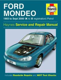
Руководство на английском языке по техническому обслуживанию и ремонту Ford Mondeo 1993-2000 года выпуска с бензиновыми двигателями.
- Автор: J. Churchill, A.K. Legg
- Издательство: Haynes Publishing
- Год издания: 1996
- Страниц: 279
- Формат: PDF
- Размер: 12,5 Mb

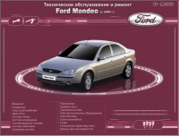
Руководство по эксплуатации и ремонту Ford Mondeo с 2007 года выпуска с бензиновыми и дизельными двигателями.
- Автор: коллектив авторов
- Издательство: ИДТР
- Год издания: 2010
- Страниц: 353
- Формат: PDF
- Размер: 264,7 Mb
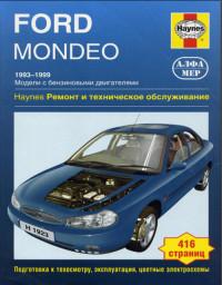
Руководство по техническому обслуживанию и ремонту Ford Mondeo 1993-1999 годов выпуска с бензиновыми двигателями.
- Автор: —
- Издательство: Алфамер
- Год издания: —
- Страниц: 393
- Формат: PDF
- Размер: 89,7Мб
Руководство по техническому обслуживанию и ремонту Ford Mondeo 2000-2003 годов выпуска с бензиновыми и дизельными двигателями.
- Автор: —
- Издательство: Алфамер
- Год издания: —
- Страниц: 472
- Формат: —
- Размер: —
Руководство для станций технического обслуживания по ремонту и обслуживанию Ford Mondeo 2002 года выпуска.
- Автор: —
- Издательство: Ford Motor Company
- Год издания: 2001
- Страниц: 2479
- Формат: PDF
- Размер: 67,4 Mb

Руководство по эксплуатации, техническому обслуживанию и ремонту + каталог расходных запчастей автомобиля Ford Mondeo 2003-2007 годов выпуска с бензиновыми и дизельными двигателями.
- Автор: —
- Издательство: Легион-Автодата
- Год издания: —
- Страниц: 470
- Формат: —
- Размер: —
Руководство по эксплуатации и ремонту Ford Mondeo 1993-2000 годов выпуска с бензиновыми и дизельными двигателями.
- Автор: —
- Издательство: Чижовка
- Год издания: 1996
- Страниц: 296
- Формат: PDF
- Размер: —

Руководство по техническому обслуживанию и ремонту Ford Mondeo с 2000 года выпуска с бензиновыми и дизельными двигателями.
- Автор: Дитер Корп, Фридрих Шредер
- Издательство: АСТ
- Год издания: 2005
- Страниц: 306
- Формат: DjVu
- Размер: 47,1 Mb
Руководство по эксплуатации Ford Mondeo 1993 года выпуска.
- Автор: —
- Издательство: Ford Motor Company
- Год издания: —
- Страниц: 140
- Формат: PDF
- Размер: 31,7 Mb
Руководство по эксплуатации Ford Mondeo 2002 года выпуска.
- Автор: —
- Издательство: Ford Motor Company
- Год издания: 2002
- Страниц: 267
- Формат: PDF
- Размер: 3,9 Mb
Руководство по эксплуатации, техническому обслуживанию и ремонту Ford Mondeo 2000-2007 годов выпуска с бензиновыми и дизельными двигателями.
- Автор: —
- Издательство: Арго-Авто
- Год издания: —
- Страниц: 504
- Формат: —
- Размер: —
Руководство по эксплуатации, техническому обслуживанию и ремонту Ford Mondeo с 2007 года выпуска с бензиновыми и дизельными двигателями.
- Автор: —
- Издательство: Арго-Авто
- Год издания: —
- Страниц: 552
- Формат: —
- Размер: —
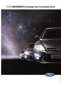
Подборка руководств по эксплуатации Ford Mondeo 2007-2014 годов выпуска.
- Автор: —
- Издательство: Ford Motor Company
- Год издания: 2007-2014
- Страниц: —
- Формат: PDF
- Размер: 133,9 Mb
Мультимедийное руководство по техническому обслуживанию и ремонту Ford Mondeo с 2000 года выпуска.
- Автор: —
- Издательство: —
- Год издания: —
- Страниц: —
- Формат: ISO
- Размер: 76,7 Mb
Руководство по эксплуатации, техническому обслуживанию и ремонту автомобиля Ford Mondeo с 2007 года выпуска с бензиновыми и дизельными двигателями.
- Автор: —
- Издательство: Третий Рим
- Год издания: —
- Страниц: 352
- Формат: —
- Размер: —

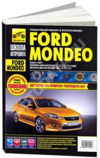
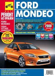 Справочно-информационное руководство для Ford Mondeo IV (с 2007 года, типы кузова – седан, универсал, пятидверный хэтчбек), с иллюстрациями. Рассматриваются вопросы технического обслуживания, ремонта и эксплуатации модели. Ниже представлены все устанавливавшиеся на автомобиль типы двигателей.
Бензиновые силовые агрегаты:
- DURATEC TI-VCT объемом 1,6 литра (110 и 125 л.с.);
- DURATEC-НЕ объемом 2 литра (145 лошадиных сил) и 2,3 литра (161 л.с.);
- DURATEC-VI5 объемом 2,5 литра (220 лошадиных сил).
- 2,5 turbo (220 л.с.)
- ECOBOOST 2,0 и (200 и 240 л.с.)
Моторы на дизельном топливе:
- Duratorq-TDCi объемом 1,8 (100 и 125 лошадиных сил)
- Duratorq-TDCi 2 (140 л.с.)
- Duratorq-TDCi 2,2 (170 л.с.).
Скачать мануал Форд Мондео 4 PDF
Описание руководства
В мануале для модели Ford Mondeo 4 (выпускаемой с 2007 года) представлено 2,8 тысяч цветных фото, на которых во всех подробностях представлен пошаговый ремонт четвертого поколения данного авто. Описываются нюансы ремонта силовых агрегатов, приведены все технические параметры транспортного средства, указаны типовые неисправности и порядок действий при необходимости ремонта.
По всем техническим операциям, связанным с разборкой, сборкой и регулированием узлов (а также с другими типами ремонта) приведена сложность работы, рекомендуемое количество исполнителей, места ремонта, требуемое время на устранение поломок.
В каждом подразделе книжки по эксплуатации, описывающем вопросы ремонта и обслуживания систем и силовых агрегатов авто указаны списки вероятных поломок и советы по восстановлению работоспособности оборудования, например указано строение и вид рулевой рейки мондео 4. Даны указания, касающиеся разборки, сборки, ремонта и регулирования узлов и систем транспортного средства в гаражных условиях, с использованием стандартного комплекта инструментов.
Технология обслуживания автомобиля разработана специально для проведения всех операций в гараже, с обычными инструментами. Только для некоторых сложных случаев даются рекомендации по применению специальных ремонтных приспособлений (находящихся в свободной продаже).
В этом электронном руководстве вашему вниманию представлено справочное издание с тысячами высококачественных цветных фото, детально отображающие ремонтные операции для автомобиля Форд Мондео IV. Описаны действия по восстановлению работоспособности всех агрегатов и функциональных элементов авто. Во всех подробностях приведено устройство четвертого поколения Ford Mondeo (с 2007 года), детализированное руководство по эксплуатации. Разделы по ремонту, представленные в руководстве.
- Manuals
- Brands
- Ford Manuals
- Automobile
- 2006 Mondeo
- Owner’s handbook manual
-
Contents
-
Table of Contents
-
Bookmarks
Quick Links
Owner’s handbook
FordMondeo
100% Ford. 100% Enjoyment.
Related Manuals for Ford 2006 Mondeo
Summary of Contents for Ford 2006 Mondeo
-
Page 1
Owner’s handbook FordMondeo 100% Ford. 100% Enjoyment. -
Page 2
This publication, or part thereof, may not be reproduced nor translated without our approval. Errors and omissions excepted. © Ford Motor Company 2006 All rights reserved. Order Code: 6S7J-19A321-ADA (CG3369en) 12/2005 20060110211039… -
Page 3: Table Of Contents
Table of Contents Introduction….5 Engine immobiliser..41 About this handbook……5 Principle of operation……41 Symbols glossary……5 Coded keys……..41 Parts and accessories……5 Arming the engine immobiliser..43 Disarming the engine immobiliser……..43 Quick start….7 Alarm……44 Child safety….18 Arming the alarm……44 Child seats……..18 Disarming the alarm……44 Child seat positioning……19 Booster cushions……21 Steering wheel…46…
-
Page 4
Table of Contents Hazard warning flashers….56 Head restraints……..92 Direction indicators……56 Rear seats……..93 Interior lamps……..57 Heated seats……..95 Changing a bulb……57 Ventilated seats…….95 Approach lamps……66 Convenience features….97 Windows and mirrors…..67 Sun visors………97 Electric windows……67 Instrument lighting dimmer….97 Exterior mirrors……..69 Clock……….97 Electric exterior mirrors….70 Cigar lighter……..97 Interior mirror……..70 Ashtray……….98… -
Page 5
Table of Contents Brakes…….118 Driving hints….133 Principle of operation…..118 Running-in……..133 Hints on driving with ABS….118 Emergency Parking brake……..119 equipment….134 Stability control..120 First aid kit……..134 Warning triangle……134 Principle of operation….120 Using stability control….120 Status after a collision….135 Traction control..121 Fuel cut-off switch……135 Principle of operation…..121 Inspecting safety system Using traction control….121… -
Page 6
Table of Contents Power steering fluid check..153 Washer fluid check……153 Technical specifications….154 Vehicle care….156 Cleaning the exterior….156 Cleaning the interior……156 Repairing minor paint damage..157 Vehicle battery..158 Battery care……..158 Using booster cables….158 Wheels and tyres..160 Changing a road wheel….160 Tyre care………166 Using winter tyres……166 Using snow chains……166 Technical specifications….167… -
Page 7: Introduction
ABOUT THIS HANDBOOK SYMBOLS GLOSSARY Warning symbols in this Congratulations on acquiring your handbook new Ford. Please take the time to get well acquainted with your vehicle by WARNING reading your owner literature. The more you know and understand How can you reduce the risk of…
-
Page 8
We would like to point out that other parts and accessories than mentioned above have not been examined and approved by Ford unless explicitly stated by Ford. In spite of continuous market product monitoring, we cannot certify the suitability of such products. Ford is not liable for any damage caused by the use of such products. -
Page 9: Quick Start
Quick start Instrument panel overview Left-hand drive E70431 Headlamp levelling control. See Headlamp levelling (page 55). Multi-function lever: direction indicators, main beam, trip computer controls. See Lighting (page 53). See Trip computer (page 78). Horn. See Horn (page 46). Instrument cluster. See Gauges (page 72). See Warning lamps and indicators (page 73).
-
Page 10
Quick start Gear selector buttons. See Automatic transmission (page 110). Hazard warning flasher switch. See Hazard warning flashers (page 56). Air vents. See Air vents (page 81). Analogue clock. See Clock (page 97). Heated windscreen switch. See Heated windows and mirrors (page 86). -
Page 11
Quick start Right-hand drive E70432 Climate controls. See Climate control (page 80). Heated windscreen switch. See Heated windows and mirrors (page 86). Heated rear window switch. See Heated windows and mirrors (page 86). Analogue clock. See Clock (page 97). Air vents. See Air vents (page 81). Hazard warning flasher switch. -
Page 12
Quick start Multi-function lever: direction indicators, main beam, trip computer controls. See Lighting (page 53). See Trip computer (page 78). Instrument cluster. See Gauges (page 72). See Warning lamps and indicators (page 73). Horn. See Horn (page 46). Wiper lever. See Windscreen wipers (page 48). Headlamp levelling control. -
Page 13
Quick start Engine warning lamp Low fuel level warning lamp Direction indicator lamp Airbag warning lamp Stability control (ESP) indicator lamp ABS warning lamp E70358 WARNING Headlamp indicator lamp Never adjust the steering wheel when the vehicle is moving. Main beam indicator lamp Manual climate control Adjusting the steering See Manual climate control (page… -
Page 14
Quick start Automatic climate control Rapid heating of the vehicle interior See Automatic climate control (page 84). E70451 Rapid cooling of the vehicle E72153 interior Recommended setting is AUTO and 22°C. Autolamps See Lighting control (page 53). E70452 Permanent comfort settings E72162 E70450… -
Page 15
Quick start Note: It is not possible to switch on the fog lamps when the lighting switch is set to AUTO. To switch on the fog lamps, switch off the autolamps feature. When the switch is set to AUTO, the dipped beam headlamps will switch on and off automatically depending on the ambient light. -
Page 16
Quick start Windscreen washers The rear wiper will follow the front wiper interval (at intermittent or normal speed). See Windscreen washers (page 49). Auto-dimming mirror See Interior mirror (page 70). E72174 E70418 Once the wash and wipe cycle is The auto-dimming mirror completed, the wipers will pause and automatically activates the dimming then perform one more wipe to clear… -
Page 17
Quick start Press twice within three seconds to Press once to unlock the vehicle. You activate double locking and arm the can change this setting (e.g. driver anti−theft alarm system. The direction door opening only). See Locking and indicators flash twice. unlocking (page 35). -
Page 18
Reverse gear — 6-speed transmission E73406 See Manual transmission (page 109). Swivel the Ford badge in the radiator grille to the side. Insert the key in the lock on the radiator grille. Turn the key first anticlockwise 1. Raise the bonnet slightly and turn the key fully clockwise 2 to open the bonnet. -
Page 19
Quick start Washer fluid reservoir See Maintenance (page 144). E73422 Front and rear washer systems are supplied from the same reservoir. The reservoir is located behind the right−hand headlamp. -
Page 20: Child Safety
Child safety Always have the rear row head CHILD SEATS restraint raised when a child restraint is being installed or occupying the seat, provided doing so does not move the child restraint away from the vehicle seat. Note: If the vehicle has been involved in an accident, have the child safety seat checked by an expert as it might be damaged.
-
Page 21: Child Seat Positioning
Child safety seat and government approved (depending on country). A choice of ECE approved child restraints is available at your Ford Dealer. Please ask for the recommended child seats. Together with the adult seat belt, these restraints help to provide maximum security for the children.
-
Page 22
U = Seat position suitable for universal category restraints approved for use in this mass/age group. = Seat position suitable for universal category restraints but Ford recommends that children should be secured in an appropriate child restraint in the rear seats. -
Page 23: Booster Cushions
Children weighing more than 15 kg BOOSTER CUSHIONS and under 150 cm should use a booster seat or booster cushion. Ford recommends using booster seats that combine a booster cushion and a back rest into one seat for children between 15 and 25 kg.
-
Page 24
Child safety E72365 E72363 Pull the unlocking lever. Push the The raised seating position makes it possible to position the seat belt cushion to the back of the seat. correctly: The shoulder strap should cross the centre of the shoulder; the lap strap should fit tightly across the hips, not the stomach. -
Page 25
Child safety Note: Before returning the booster cushion to its original position, make sure there are no objects hidden under it. Proceed in reverse order. Make sure that the locking mechanism engages properly. Vario child safety seat E72368 Note: Refer also to the instructions provided with the child safety seat. -
Page 26: Child Safety Locks
Child safety CHILD SAFETY LOCKS E72192 WARNING When the child safety lock is activated, the door can only be opened from outside. Turn the key in the rear door outwards to activate the lock. To deactivate the lock, turn the key inwards.
-
Page 27: Occupant Protection
Occupant protection PRINCIPLE OF OPERATION Airbags E72324 WARNING • crash sensors. Do not modify the front of the • a warning lamp in the instrument vehicle in any way, as this can panel. adversely affect the airbag • an electronic control and deployment.
-
Page 28
Occupant protection The seat and back must be set WARNINGS correctly for the airbags to be Repairs to either of the front optimally effective. See Sitting in the seat covers, the sensors correct position (page 90). attached to the seats as well as to the roof lining should only be carried This is the ideal seating position for out by properly trained technicians. -
Page 29
Occupant protection These areas should only be wiped with a damp cloth, never with a wet cloth. Dual-stage strategy A system of sensors in the vehicle monitors vehicle speed, the status of the seat belt and the position of the driver s seat. -
Page 30
Occupant protection A label on the seatback indicates that The curtain air bags are not activated side airbags are fitted. The side upon minor lateral collisions nor upon airbags are fitted on the side of the front or rear impacts. seatbacks of the front seats. -
Page 31: Seat Belt Reminder
Occupant protection Deactivating the seat belt The restraint system, with belt pretensioners in the front seat, helps reminder to reduce the risk of serious injury in To deactivate the seat belt reminder a head-on collision. During a serious for one ignition cycle, buckle and crash the seat belts are pretensioned unbuckle the seat belt within 3 to help reduce slack in the belt.
-
Page 32: Seat Belt Height Adjustment
Occupant protection SEAT BELT HEIGHT WARNING ADJUSTMENT Insert the tongue into the buckle until a distinct click is heard, otherwise the seat belt will not be locked correctly. Pull the belt out steadily. It may lock if pulled sharply or if the vehicle is on a slope.
-
Page 33: Using Seat Belts During Pregnancy
Occupant protection The lap strap should be fitted USING SEAT BELTS comfortably across the hips, low DURING PREGNANCY beneath the pregnant abdomen. The diagonal part of the seat belt should be placed between the breasts, and worn above and to the side of the pregnant abdomen.
-
Page 34: Keys And Remote Controls
Keys and remote controls GENERAL INFORMATION ON RADIO FREQUENCIES See Type approvals (page 183). WARNINGS The radio frequency used by the remote control can also be used by other short distance radio transmissions (e.g. amateur radios, E72191 medical equipment, wireless headphones, remote controls, alarm To programme a new remote systems etc.).
-
Page 35: Changing The Remote Control Battery
Keys and remote controls Re-programming the CHANGING THE REMOTE unlocking function CONTROL BATTERY You can change the unlocking If the range of the transmitter in the function so that pressing the unlock key decreases gradually, the battery button once deactivates the central (type 3V CR 2032) should be locking or double locking, disarms replaced.
-
Page 36
Keys and remote controls E68729 • Carefully prise out the battery with the flat object. Fit the new battery between the contacts with the + sign facing downwards. Reassemble the transmitter unit in reverse order. -
Page 37: Locks
Locks Locking and unlocking from LOCKING AND the inside UNLOCKING Doors Locking and unlocking from the outside E72194 When inside the vehicle, all doors can be locked with the locking button A on the driver s door and unlocked using the door handle B. To lock the E72193 passenger s door and the rear doors individually, depress the locking…
-
Page 38
Locks Central and double locking • using the remote control. • using the tailgate release switch in the handle. • using the key (4-door saloon). Closing the tailgate E72196 E72197 WARNING WARNING Double locking should not be Close the tailgate properly to activated when people are prevent it opening while you are inside the vehicle. -
Page 39
Locks Right-hand drive E72198 Double locking is an additional theft protection feature which prevents the vehicle s doors from being opened from inside the vehicle. Double locking is possible only if all doors are closed. E72200 With the key: Turn the key in the Unlocking the vehicle driver s door to position A. -
Page 40
Locks With the remote control: Press Locking the vehicle the unlock button once. Left-hand drive One flash of the direction indicators confirms that all doors have been unlocked, that the double locking system is deactivated and that the anti-theft alarm system is disarmed. Automatic relocking To prevent the vehicle being left unlocked inadvertently, central… -
Page 41
Locks Right-hand drive E72207 With the remote control: Press the lock button once. It is not possible to lock the front E72209 doors by remote control when the With the key: Turn the key in the tailgate is open. driver s door to position A and then On vehicles without double locking, to position B within two seconds. -
Page 42: Global Opening And Closing
Locks Global closing GLOBAL OPENING AND CLOSING Global opening E72210 E72203 E72207 WARNING Take care when using global closing. In an emergency, press a button immediately to stop. E72201 To close all the windows and the To open all the windows and the sunroof, press and hold the lock sunroof, press and hold the unlock button for at least two seconds.
-
Page 43: Engine Immobiliser
Engine immobiliser PRINCIPLE OF OPERATION The engine immobilisation system is a theft protection feature which prevents the engine from being started with an incorrectly coded key. CODED KEYS E66505 E66506 Key coding Your vehicle is supplied with coded A maximum of eight keys (including keys.
-
Page 44
Engine immobiliser 3. Insert the second key in the ignition switch and turn to position 4. Turn the second key back to position 0 and remove from the ignition switch − the key coding mode is now activated. 5. If an uncoded key is now inserted E66508 in the ignition switch and turned to position II within 10 seconds,… -
Page 45: Arming The Engine Immobiliser
Engine immobiliser ARMING THE ENGINE IMMOBILISER E70359 The system is armed five seconds after switching off the ignition. The indicator lamp in the clock will flash. DISARMING THE ENGINE IMMOBILISER Switching on the ignition disarms the system if the correct code is recognised.
-
Page 46: Alarm
Alarm Automatic arming delay ARMING THE ALARM Up to 20 seconds after activating the Note: If the vehicle is locked with the anti-theft alarm system, it is still key, this does not activate the alarm possible to open the vehicle again system (vehicles with 3.0 l Duractec−…
-
Page 47
Alarm The anti-theft alarm system for the tailgate is deactivated when the luggage compartment is unlocked with a key (4-door models) or the remote control (all models). After closure, the alarm is once again armed. Vehicles with 3.0 l Duratec- VE/-ST or 2.5 l Duratec-VE engine Note: Unlocking a front door with a… -
Page 48: Steering Wheel
Steering wheel ADJUSTING THE HORN STEERING WHEEL E70360 The horn can also be operated when the ignition is off. E70358 AUDIO CONTROL WARNING Never adjust the steering wheel Select radio, CD or cassette mode when the vehicle is moving. on the audio unit. The following functions can be Release the locking lever to adjust operated with the remote control:…
-
Page 49: Voice Control
Steering wheel Volume down: Pull the VOL− switch Note: If the voice control system towards the steering wheel. and/or a mobile phone kit is equipped, the MODE function does Seek not control the audio system. Briefly press the button on the side: •…
-
Page 50: Wipers And Washers
Wipers and washers Autowipers WINDSCREEN WIPERS WARNINGS In icy conditions, make sure that the windscreen has been fully defrosted before selecting autowipers. Switch off the autowipers feature before entering a car wash. Replace the wiper blades as soon as they begin to leave bands of water and smears or when they do not completely remove water from the windscreen.
-
Page 51: Windscreen Washers
Wipers and washers When autowipers is selected, the WINDSCREEN WASHERS wipers will cycle once regardless of whether the windscreen is wet or dry. Thereafter, or when the ignition is switched on with autowipers selected, the wipers will not cycle until water is detected on the windscreen.
-
Page 52: Rear Window Wiper And Washers
Wipers and washers Washer REAR WINDOW WIPER AND WASHERS Intermittent wiping E72176 E72175 WARNING Pull the lever towards the steering Do not operate the washer for wheel. more than 10 seconds at a time, Reverse gear wipe and never when the reservoir is empty.
-
Page 53: Adjusting The Windscreen Washer Jets
Wipers and washers ADJUSTING THE WARNING WINDSCREEN WASHER Do not operate the washer for more than 10 seconds at a time, JETS and never when the reservoir is empty. The headlamp washers operate when the exterior lights are switched on and the windscreen washer is used.
-
Page 54: Changing The Wiper Blades
Wipers and washers CHANGING THE WIPER BLADES E66645 Lift the wiper arm and position the wiper blade at a right angle to the wiper arm. To remove, press the retaining clip in the direction of the arrow, disengage the wiper blade and pull it off the arm in the opposite direction.
-
Page 55: Lighting
Lighting LIGHTING CONTROL WARNING The autolamps feature is an Lighting control positions auxiliary system which is not intended to relieve the driver of his responsibility for the vehicle s exterior lighting. When the switch is set to AUTO, the dipped beam headlamps will switch on and off automatically depending on the ambient light.
-
Page 56: Front Fog Lamps
Lighting Headlamp flasher The front fog lamps should be used only when visibility is considerably restricted by fog, snow or rain. REAR FOG LAMPS E72168 Pull the lever slightly towards the steering wheel. FRONT FOG LAMPS E72164 WARNING The rear fog lamps may only be used when visibility is restricted to less than 50 m and must not be used when it is raining or snowing.
-
Page 57: Adjusting The Headlamps
Lighting Vehicles with Xenon headlamps are ADJUSTING THE fitted with automatic headlamp HEADLAMPS levelling. The headlamps can be adjusted for Vehicles with Xenon driving on the left or right hand side headlamps of the road i.e. when travelling abroad. This adjustment should only be carried out by an expert.
-
Page 58: Hazard Warning Flashers
Lighting Recommended headlamp levelling control positions Load Control position Persons Load in Saloon Estate luggage Front seats Rear seats without with self- compart- self-level. level. susp. ment susp. max. max. See Technical specifications (page 173). Control position must be increased by 0.5 on vehicles with 2.0 l Duratorq-TDCi or 2.5 l Duratec-VE engines and automatic transmission.
-
Page 59: Interior Lamps
Lighting Reading lamps Briefly tap the lever up or down and the direction indicators will flash three times. INTERIOR LAMPS E72171 CHANGING A BULB WARNINGS E72170 On vehicles fitted with Xenon headlamps, have the headlamp Door contact bulbs changed by an expert. There is a risk of injury due to high voltage.
-
Page 60
Lighting Headlamps, side lamps, Grasp one of the tabs and pull out direction indicators the retaining pin. Repeat with the other tab. Note: It is necessary to remove the Carefully pull out the headlamp headlamp assembly to remove any assembly and disconnect the wiring of the bulbs. -
Page 61
Lighting When installing in the reverse order, make sure the clips engage properly. Headlamps – dipped beam H7, 55 watt halogen bulb E72539 • Turn the cover anticlockwise, and remove. • Using a flat-bladed screwdriver, carefully prise out the socket. •… -
Page 62
Lighting • Slide the lamp assembly downwards and pull it out. • Grasp the bulb holder, turn the lamp housing anticlockwise and remove it. • Pull the bulb out. Install in the reverse order. Approach lamps E72542 • Disconnect the wiring connector. •… -
Page 63
Lighting • Loosen the screw in the fog lamp bezel. Prise out the fog lamp bezel. • Loosen the screws, and pull out the lamp assembly. • Disconnect the wiring connector. • Pull the bulb out and replace it. Install in the reverse order. Fog lamps (ST variants) H7, 55 watt E72546… -
Page 64
Lighting From inside the luggage Turn the bulb anticlockwise under compartment, release the rotary clips slight pressure, and remove it. of the rear light assembly cover. Replace the bulb. Remove the cover. Install in the reverse order. After installation, check that the lights operate correctly. -
Page 65
Lighting E72553 Pull the cover off. E72551 Turn the bulb anticlockwise under slight pressure, and remove it. E72555 • Disconnect the wiring connector, and take out the lamp assembly. • Press the catches and pull off the cover. • Pull the bulb out and replace it. E72552 Install in the reverse order. -
Page 66
Lighting Front interior lamp Remove the two screws, and take off the cover. 10 watt festoon bulb E72555 • Disconnect the wiring connector, and take out the lamp assembly. E72557 • Press the catches and pull off the cover. • Switch off the interior lights •… -
Page 67
Lighting • Switch off the interior lights (left-hand switch position). • Prise out the lamp assembly in the recess at the side opposite the switch with a flat-bladed screw driver. • Remove the reflector, and replace the bulb. Install in the reverse order. E72560 Sun visor lamps The bulbs can be replaced after the… -
Page 68: Approach Lamps
Lighting Carefully prise out the lamp assembly from the holder with a flat-bladed screwdriver, and remove the bulb. Install in the reverse order. APPROACH LAMPS E72169 The approach lamps will switch on automatically when the doors are unlocked or opened. When closing the doors, the approach lamps will switch off automatically after a short period of time or when the ignition is…
-
Page 69: Windows And Mirrors
Windows and mirrors Opening and closing a ELECTRIC WINDOWS window automatically WARNING Before operating the electric windows you should verify they are free of obstructions and ensure that children and/or pets are not in the proximity of window openings. Failure to do so could result in serious personal injury.
-
Page 70
Windows and mirrors Window anti-trap Resetting the electric protection window memory WARNINGS Anti-trap protection is not active while the electric window memory is being reset. Make sure that there are no obstacles in the way of the closing window. Careless closing of the electric windows can override the anti-trap protection and cause injuries. -
Page 71: Exterior Mirrors
Windows and mirrors EXTERIOR MIRRORS WARNING Objects seen in these mirrors Manual exterior mirrors will look smaller and appear further away than they actually are. Be careful not to over estimate the distance of the objects seen in the mirrors. In both mirrors the rearward field of vision is increased to minimise the so-called blind spot at the rear…
-
Page 72: Electric Exterior Mirrors
Windows and mirrors Electric folding mirrors ELECTRIC EXTERIOR MIRRORS E72184 In the centre position push the control unit down. To return the door E66485 mirror to its original position, push the Left-hand mirror control unit down again. Right-hand mirror INTERIOR MIRROR The mirrors are heated when the heated rear window is switched on.
-
Page 73
Windows and mirrors Auto-dimming mirror E70418 The auto-dimming mirror automatically activates the dimming function when hit by glaring light from behind. The function is automatically deactivated when reverse gear is selected. -
Page 74: Instruments
Instruments GAUGES E70433 Engine coolant temperature gauge Tachometer Speedometer Fuel gauge Tripmeter reset button Odometer and tripmeter Information display Trip computer reset button If the needle enters the red section, Engine coolant temperature the engine is overheating. Switch off gauge the ignition and determine the source of the problem once the engine has At normal operating temperature, the…
-
Page 75: Warning Lamps And Indicators
Instruments Tachometer Information display On vehicles with a diesel engine, the tachometer goes to 5 000 revolutions per minute. Fuel gauge The arrow adjacent to the fuel pump symbol indicates on which side of the vehicle the fuel filler cap is located. Odometer and tripmeter E70434 Cruise control indicator…
-
Page 76
Instruments Brake system and ABS • Engine warning lamps • Stability control (ESP) • Ignition WARNING • Low washer fluid Reduce vehicle speed gradually. • Oil pressure Use the brake with great care. Do not step on the brake pedal •… -
Page 77
Instruments Engine warning lamp Headlamp indicator lamp The engine warning lamp Illuminates when the should extinguish as soon headlamps are on dipped as the engine starts. If it beam or when the side and illuminates with the engine running, it tail lamps are on. -
Page 78: Audible Warnings And Indicators
Instruments Oil pressure warning lamp Stability control (ESP) indicator lamp If the lamp stays on after starting or illuminates during Note: If the it does not illuminate a journey, stop immediately, when the ignition is switched on or if switch off the engine and check the it stays illuminated whilst driving, it engine oil level.
-
Page 79
Instruments Overspeed A warning tone will sound if the vehicle speed exceeds 120 km/h (70 mph). Seat belt reminder A warning tone will sound if the driver’s seat belt is unbuckled. -
Page 80: Information Displays
Information displays TRIP COMPUTER WARNING For road safety reasons, set and reset the functions only whilst the vehicle is stationary. Press to change between functions. You will hear an audible signal every time you press the button. Reset button E70435 The following functions are available when the ignition is on: •…
-
Page 81
Information displays Instantaneous fuel Shows the outside air temperature. At temperatures of +4 ºC or lower consumption the frost warning lamp will illuminate. See Warning lamps and indicators (page 73). Remaining fuel range E70441 The instantaneous fuel consumption is indicated when the vehicle speed is above 6,5 km/h (4 mph). -
Page 82: Climate Control
Climate control Heating PRINCIPLE OF OPERATION The heating depends upon the coolant temperature and is therefore Outside air only effective when the engine is warm. Always keep the air intakes forward of the front windscreen free of snow, Air conditioning leaves etc., to allow the system to function effectively.
-
Page 83: Air Vents
Climate control Blower AIR VENTS E70444 Press the left−hand button to reduce the blower speed and thus the amount of air. E70416 Open Press the right−hand button to increase the blower speed and thus Closed the amount of air. The blower setting is indicated in the MANUAL CLIMATE display.
-
Page 84
Climate control Rapid window To switch on/off the cooling effect, defrosting/demisting press the A/C button. A/C is indicated in the display when the cooling effect is switched on. Recirculated air E70446 As long as the button is selected, recirculated air cannot be selected and the air conditioning cannot be E70448 switched off. -
Page 85
Climate control Rapid heating of the vehicle Press the OFF button to switch off the entire system. The climate control interior system is switched off and recirculated air is selected. If the ON button is pressed, the system returns to the previous settings. -
Page 86: Automatic Climate Control
Climate control E70453 E72153 In very humid weather and to Pressing the AUTO button once maximize the cooling effect, also switches on the AUTO mode. switch on the recirculated air and set Setting the temperature the blower to high speed. AUTOMATIC CLIMATE CONTROL Note: Note: The automatic climate…
-
Page 87
Climate control To toggle between °Celsius and Press the A/C button to switch the °Fahrenheit, press both blower air conditioning on and off. ECO buttons and the recirculated air appears in the display when the air button simultaneously for at least two conditioning is switched off. -
Page 88: Heated Windows And Mirrors
Climate control Heated rear window HEATED WINDOWS AND MIRRORS Heated windows Use for quick defrosting or demisting of the windscreen or rear window. It should be switched on only if necessary. E72159 Vehicles with a diesel engine The heated windscreen and heated rear window will be switched on and then off automatically at low ambient temperatures and low engine…
-
Page 89: Auxiliary Heater
Climate control AUXILIARY HEATER WARNING Before operating the electric The auxiliary heater aids in warming sunroof you should verify it is the engine and the interior free of obstructions and ensure that compartment. It is integrated into the children and/or pets are not in the cooling system and is automatically proximity of the sunroof opening.
-
Page 90
Climate control Opening and closing the sunroof E72185 Press to open Press to close E72188 Opening and closing the sunroof automatically Momentarily press the open or close button to open or close the sunroof automatically. Press the button a second time to stop the sunroof opening or closing. -
Page 91
Climate control The electric sunroof is equipped with • Tilt the rear of the sunroof as far anti-trap protection. The sunroof will as possible. Release the button. stop automatically while closing and • Press and hold the same button reverse some distance if there is an again for 30 seconds until you see obstacle in the way. -
Page 92: Seats
Seats SITTING IN THE MANUAL SEATS CORRECT POSITION WARNING Do not adjust the seats while the vehicle is moving. Moving the seats forwards or backwards E66528 • Sit in an upright position with the base of your spine as far back as possible and with the backrest E72312 reclined no more than 30…
-
Page 93: Electric Seats
Seats Adjusting the lumbar ELECTRIC SEATS support 2-way electric seat E72313 E72315 Turn the handwheel located on the side of the seatback. 8-way electric seat Adjusting the angle of the seatback E72316 E72314 When the seats are slid fully forward the seatbacks can be fully reclined.
-
Page 94: Head Restraints
Seats The front head restraints are equipped with an additional safety feature. In case of a rear impact, they will move forward, thereby cushioning the occupants heads. This reduces the risk of whiplash injuries. To raise: Pull the head restraint up. To lower: Press the locking button and push the head restraint down.
-
Page 95: Rear Seats
Seats REAR SEATS WARNING Always have the rear head Folding the rear seatback restraint raised when the rear forwards seat is occupied by a passenger or a child restraint. 5-door and Estate To raise: Pull the head restraint up. To lower the outer head restraints: Press both locking buttons and push the head restraint down.
-
Page 96
Seats Pull one or both unlocking knobs in the luggage compartment and fold the seatback forwards. Returning the seatback to its upright position The seatback must engage in the latches on both sides. The seat belts must be forward of the seatback. Folding rear seat cushions and seatback forwards E72323… -
Page 97: Heated Seats
Seats Recommended settings HEATED SEATS Use step 1 or 2 for heating of the seat with a comfortable temperature for longer periods. The steps 4 and 5 are only recommended for short periods with a high difference in temperature. VENTILATED SEATS E72311 WARNING Heating with the engine off will…
-
Page 98
Seats Press the + button repeatedly to raise the temperature. Pressing the – button repeatedly will lower the temperature. The number of illuminated lights beside the button indicates the selected step. The heater setting is indicated in red, the cooler setting in blue. When no light is illuminated, the ventilation of the seat is switched off. -
Page 99: Convenience Features
Convenience features SUN VISORS CLOCK E70421 The time is adjusted by pressing the button. To advance the minutes, E70419 press the button briefly. To advance The sun visors can be released from rapidly, hold the button pressed. the retention clips and swivelled towards the side window.
-
Page 100: Ashtray
However, if the engine is not running, this will cause the battery to discharge. When connecting appliances, use only specified connectors from the Ford Accessory range or connectors for use with SAE standard sockets. ASHTRAY E70424 To empty, take out the insert.
-
Page 101: Auxiliary Power Sockets
10 amperes. However, if the engine is not running, this will cause the battery to discharge. When connecting appliances, use only specified connectors from the Ford Accessory range or connectors for use with SAE standard sockets. CUP HOLDERS E70420 Press to open.
-
Page 102: Starting The Engine
Starting the engine Position I GENERAL INFORMATION Steering unlocked. Ignition and all General points on starting main electrical circuits are disabled. The ignition key should not be left in If the battery has been disconnected this position for too long to avoid the vehicle may exhibit some unusual discharging the battery.
-
Page 103: Starting A Diesel Engine
Starting the engine Do not operate the starter for longer STARTING A DIESEL than 30 seconds at a time. Release ENGINE the ignition key as soon as the engine has started. If the engine has not General points on starting started, return the ignition key to position 0 and repeat the starting procedure.
-
Page 104: Switching Off The Engine
Starting the engine Wait until the lamp extinguishes If the engine is switched off at high before starting and continue cranking speed, the turbocharger will continue without pausing until the engine running after the engine oil pressure starts. has dropped to zero. This will lead to premature turbocharger bearing If the engine stalls, repeat the full wear.
-
Page 105: Fuel And Refuelling
Fuel and refuelling Prolonged use of supplemental SAFETY PRECAUTIONS additives to prevent fuel waxing is not recommended. Do not add WARNINGS kerosene, paraffin or petrol to diesel To avoid fuel spillage that could fuels. be hazardous to other road users, always stop refuelling after the CATALYTIC CONVERTER fuel nozzle stops the second time.
-
Page 106: Fuel Filler Flap
Fuel and refuelling When the filler cap is removed, a FUEL FILLER FLAP hissing noise may be heard. This is normal and should be disregarded. To refit the cap, turn clockwise until it clicks. REFUELLING WARNING If you fill your vehicle with incorrect fuel or additives, do E72501 not attempt to start the engine.
-
Page 107
Fuel and refuelling Urban Extra-urban Combined emissions Variant l/100 km l/100 km l/100 km g/km (mpg) (mpg) (mpg) 1.8 l Duratec-HE 92 kW (125 PS), Stage IV 11.3 (25.0) 5.6 (50.4) 7.7 (36.7) emissions 1.8 l Duratec-SCi 96 kW 9.9 (28.5) 5.7 (49.6) 7.2 (39.2) (130 PS) -
Page 108
Fuel and refuelling Urban Extra-urban Combined emissions Variant l/100 km l/100 km l/100 km g/km (mpg) (mpg) (mpg) 2.0 l Duratorq-TDCi 85 kW (115 PS), Stage IV 8.1 (34.9) 4.8 (58.9) 6.0 (47.1) emission, 6-speed manual 2.0 l Duratorq-TDCi 85 kW 10.2 (27.7) 5.8 (48.7) 7.4 (38.2) -
Page 109
Fuel and refuelling Urban Extra-urban Combined emissions Variant l/100 km l/100 km l/100 km g/km (mpg) (mpg) (mpg) 1.8 l Duratec-SCi 96 kW (130 PS), Stage IV 10.1 (28.0) 5.9 (47.9) 7.4 (38.2) emissions 2.0 l Duratec-HE, Stage III 11.3 (25.0) 6.0 (47.1) 8.0 (35.3) emissions, Manual… -
Page 110
Fuel and refuelling Urban Extra-urban Combined emissions Variant l/100 km l/100 km l/100 km g/km (mpg) (mpg) (mpg) 2.0 l Duratorq-TDCi 85 kW (115 PS), Stage IV 8.3 (34.0) 5.0 (56.5) 6.2 (45.6) emission, 6-speed manual 2.0 l Duratorq-TDCi 85 kW 10.2 (27.7) 5.9 (47.9) 7.5 (37.7) -
Page 111: Transmission
Transmission To select the reverse gear, shift the MANUAL TRANSMISSION lever into the neutral position and then press the lever fully to the right WARNINGS against a spring pressure, before Engage reverse gear only when pulling rearwards. the vehicle is stationary. Reverse gear −…
-
Page 112: Automatic Transmission
Transmission Gear selection AUTOMATIC TRANSMISSION E72457 E72458 4-speed transmission 5-speed transmission WARNING (Durashift 5-tronic) When the vehicle is stationary, apply the parking brake or Depending on the model variant, the depress the footbrake before transmission in your vehicle is a 4- or selecting a gear.
-
Page 113
Transmission P = Park Depress the brake pedal when selecting R. WARNINGS N = Neutral This position should be selected only when the vehicle is WARNING stationary. In this position, you have to Always apply the parking brake depress the brake pedal or and make sure that the selector apply the parking brake to prevent lever is securely latched in P. -
Page 114
Transmission 1 = Gear 1 (4-speed transmission) The transmission remains in the first gear. For extreme downhill gradients. Manual shifting (5-speed transmission) E72461 To shift down, gently push the gearshift lever forwards (−) or press a − button on the steering wheel spokes. -
Page 115
Transmission The multifunction display shows the Overdrive (4-speed current selector lever position PRN transmission) or D and AUTO when the selector lever is in the left gate (automatic shifting) or 1234 or 5 and MAN when the selector lever is in the right gate (manual shifting). -
Page 116
Transmission Depress the overdrive button again Moving off in sand, mud and to reactivate. When the engine is snow switched on, the overdrive function is automatically selected. If the indicator flashes a problem has been detected in the automatic transmission. Have your vehicle checked by an expert as soon as possible. -
Page 117
Transmission The automatic transmission can provide increased torque for steep gradients or for overtaking. To achieve this kickdown effect, depress and hold the accelerator pedal fully in the selector lever position D. The same effect can be achieved in manual mode at low or moderate vehicle speed (5-speed transmission only). -
Page 118
Transmission Emergency park position Note: If position P is selected again, release lever this procedure must be repeated. It enables the selector lever to be moved out of the park position P in the event of a discharged battery or electrical failure. -
Page 119
Transmission Downhill mode Neutral idle control (2.0 l Duratorq-TDCi) The transmission recognizes downhill driving conditions and supports your To increase your comfort, engine braking manoeuvre by downshifting noise and vibration characteristics will to increase engine braking. be optimised if the vehicle stands still with the engine sunning, the selector Uphill mode lever in D and the footbrake is… -
Page 120: Brakes
Brakes After leaving a carwash or driving the PRINCIPLE OF vehicle through water, dab the brake OPERATION pedal while driving to remove the film of water. Dual circuit braking system Emergency brake assist WARNING WARNING If a brake circuit fails, you will at first experience a softer feel to Emergency brake assist is an the brake pedal.
-
Page 121: Parking Brake
Brakes • If your vehicle is parked on a hill and facing uphill, select first gear and turn the steering wheel away from the kerb. • If your vehicle is parked on a hill and facing downhill, select reverse E66566 gear and turn the steering wheel The ABS operates only when the towards the kerb.
-
Page 122: Stability Control
Stability control ESP provides an enhanced traction PRINCIPLE OF control function by reducing wheel OPERATION spin at the driven wheels when accelerating. This improves the ability Electronic stability program to pull away on slippery roads or (ESP) loose surfaces. The system also supports stability by counteracting the tendency of the vehicle to swerve away from the intended path.
-
Page 123: Traction Control
Traction control When the ignition is switched on PRINCIPLE OF (position II), the system is OPERATION automatically enabled and the lamp in the switch illuminates briefly to WARNING confirm that the system is Drivers should never take operational. unnecessary risks even though When the traction control system is the system offers inherently safer activated, as indicated by the flashing…
-
Page 124: Self-Levelling Suspension
Self-levelling suspension PRINCIPLE OF OPERATION E72517 When self-levelling rear suspension is fitted, the vehicle will ride at approximately the same height irrespective of the load. When driving, the system maintains the correct ride height automatically, whether weight is added or removed. If a headlight levelling system is fitted, pay attention that the appropriate switch position is used.
-
Page 125: Parking Aid
Parking aid Note: If the vehicle is fitted with an PRINCIPLE OF original Ford fixed tow bar, particular OPERATION care must be taken when reversing. The system is activated automatically WARNING after the reverse gear is selected with The parking aid is an auxiliary the ignition switched on.
-
Page 126: Cruise Control
Cruise control PRINCIPLE OF USING CRUISE CONTROL OPERATION Switching cruise control on and off WARNING Don not use cruise control in heavy traffic, on twisty roads or when the road surface is slippery. The cruise control system automatically adjusts the power E72177 output of the engine to maintain the stored speed.
-
Page 127
Cruise control Changing the stored vehicle speed Press SET+ to accelerate. Press the — to decelerate. Vehicle speed will change without the need to depress the accelerator pedal. The speed at which the switch is released becomes the new stored speed. -
Page 128: Load Carrying
Load carrying Driving with the tailgate/rear GENERAL INFORMATION door open is potentially dangerous as exhaust fumes may be drawn into the vehicle s interior. CARGO NETS E72508 E72510 E72509 WARNINGS If objects have to be placed in the vehicle, secure them from moving.
-
Page 129: Luggage Covers
Load carrying Estate A luggage net can be attached to the four retaining points on the load area floor. It can prevent objects sliding around. LUGGAGE COVERS WARNING Do not place objects on the luggage cover. 5-door Removal E72513 Pull out the roller cover and secure in the retaining points.
-
Page 130
Roof rails (Estate) The side mounting rails are designed so that racks (for bicycles, skis etc.) from the Ford accessories range can E72516 be fitted. Loads should be evenly distributed on the cross rails and/or Note: Take care not to install the the side rails. -
Page 131: Towing
Towing TOWING A TRAILER ESSENTIAL TOWING CHECKS Note: Mondeo ST vehicles are not approved for trailer towing. WARNING The maximum vehicle and trailer If any of the following conditions payloads represent technically cannot be met, do not use the binding values for gradients up to 12 tow bar and have it inspected by an % and at an altitude of 1 000 metres expert.
-
Page 132: Detachable Tow Ball
Towing Removing the tow ball DETACHABLE TOW BALL WARNINGS Remove and reinstall the tow ball regularly to keep the locking mechanism working smoothly. Do not use any tools for mounting/dismounting the tow ball. Do not modify the trailer coupling. Do not disassemble/repair the tow ball.
-
Page 133
Towing • Insert the plug. • Remove the cover (depending on model variant) from the rear bumper. Grab the cover from underneath with both hands and carefully pull it off downwards. E72522 • Pull out the plug. E72527 • Insert the cover from underneath until it engages. -
Page 134
Towing • Insert the tow ball horizontally and push forward until the locking mechanism engages. (Do not hold your hand near the locking mechanism.) • The tow ball locks automatically. Lever 1 must be in its original position (right-hand side). •… -
Page 135: Driving Hints
500 km (1 000 miles) on motorways. From 1 500 km (1 000 miles) onwards you can gradually increase the performance of your vehicle up to the permitted maximum speeds. We wish you safe and pleasurable driving with your Ford vehicle.
-
Page 136: Emergency Equipment
Emergency equipment Estate FIRST AID KIT Storage for a warning triangle is 4-door and 5-door located on the left-hand side of the luggage compartment. Vehicles with a temporary spare wheel Storage for a first aid kit is located on either side of the luggage compartment.
-
Page 137: Status After A Collision
Status after a collision Resetting the switch FUEL CUT-OFF SWITCH WARNING Vehicles with a Duratec Do not reset the fuel cut-off engine switch if you see or smell leaking fuel. • Turn the ignition switch to position • Check fuel system for leaks. •…
-
Page 138: Fuses
Fuses Auxiliary fuse box FUSE BOX LOCATIONS WARNING Any improper alterations to the electrical or fuel system can endanger the safety of the vehicle as they could constitute a fire hazard or cause engine damage. Have any work involving these systems or the replacement of relays or high current carrying fuses carried out by an expert.
-
Page 139: Changing A Fuse
Fuses The central fuse box is located The central fuse box is located behind the storage compartment behind the glove compartment. To underneath the instrument panel. To remove the glove compartment, remove the storage compartment, open it and push the lever at the open it and pull it outwards.
-
Page 140
Fuses Auxiliary fuse box Fuse Circuits protected 16/18 Conventional headlamps: 7.5 A; Xenon headlamps: 20 A Automatic transmission: 10 A Auxiliary heater (Diesel): 20 A; Battery Backed−up Sounder (ST): 7.5 A Diode electronic module Diode air conditioning Diode engine cooling fan HO2S sensor Engine Control Valves/Vehicle Speed Sensor Engine management Duratec engines: 10 A;… -
Page 141
Fuses Front fog lamps Electric front windows Rear fog lamps Sunroof Reversing lamp Electric seats Dipped beam or parking Heated and ventilated seats lamp switch Parking lamps Heated seats Interior lamps Heater blower motor Headlamp washers Air conditioning, heater blower motor Windscreen wipers, Air conditioning windscreen wiper switch… -
Page 142
Fuses Ignition, ignition switch Fuel pump Auxiliary or fuel fired heater, glow plugs (diesel), fuel injection pump relay (diesel) Battery sensing Engine cooling fan Automatic transmission Auxiliary power sockets Battery positive feed Diode… -
Page 143: Vehicle Recovery
Vehicle recovery TOWING POINTS WARNING The towing eye has a left-hand thread. Install it by turning anticlockwise. Tighten by hand. Prise off the cover in the bumper with a flat-bladed screwdriver and install the towing eye. E73302 The screw-in towing eye is stored with the jack in the luggage compartment.
-
Page 144: Transporting The Vehicle
Vehicle recovery TRANSPORTING THE VEHICLE Vehicles with an automatic transmission E73304 WARNING Never tow a vehicle with an automatic transmission faster than 50 km/h (30 mph) or further than 50 kilometres (30 miles). If it is necessary to tow the vehicle a greater distance, the drive wheels must be lifted clear off the ground.
-
Page 145: Towing The Vehicle On Four Wheels
Vehicle recovery Never tow a vehicle backwards TOWING THE VEHICLE with the drive wheels turning. If ON FOUR WHEELS this instruction is not adhered to, it could cause damage to the All vehicles automatic transmission. WARNING When a vehicle with an automatic The ignition key must be set to transmission is towed, the selector position II when the vehicle is…
-
Page 146: Maintenance
Maintenance Every day check GENERAL INFORMATION • Operation of all exterior and WARNINGS interior lamps and make sure that The electronic ignition system all lenses are clean. works with high voltage. Never When filling up check touch these components with the engine running or the ignition •…
-
Page 147: Engine Compartment Overview
Maintenance ENGINE COMPARTMENT OVERVIEW Duratec-HE/SCi E73408 Engine coolant reservoir Power steering fluid reservoir Engine oil filler cap* Brake/clutch fluid reservoir Air cleaner Auxiliary fuse box Battery Engine oil dipstick* Washer fluid reservoir * For easy identification, filler caps and the engine oil dipstick are marked in colour.
-
Page 148
Maintenance Duratec-VE E73409 Engine coolant reservoir Power steering fluid reservoir Engine oil filler cap* Brake/clutch fluid reservoir Air cleaner Auxiliary fuse box Battery Engine oil dipstick* Washer fluid reservoir * For easy identification, filler caps and the engine oil dipstick are marked in colour. -
Page 149
Maintenance Duratec-VE/ST V6 E73410 Engine coolant reservoir Power steering fluid reservoir Engine oil filler cap* Brake/clutch fluid reservoir Air cleaner Auxiliary fuse box Battery Engine oil dipstick* Washer fluid reservoir * For easy identification, filler caps and the engine oil dipstick are marked in colour. -
Page 150
Maintenance Duratorq-TDDi/-TDCi Turbodiesel E73411 Engine coolant reservoir Power steering fluid reservoir Engine oil filler cap* Brake/clutch fluid reservoir Air cleaner Auxiliary fuse box Battery Engine oil dipstick* Washer fluid reservoir * For easy identification, filler caps and the engine oil dipstick are marked in colour. -
Page 151: Opening And Closing The Bonnet
ENGINE OIL CHECK The bonnet must be opened from the outside. WARNING Swivel the Ford badge in the radiator Do not use oil additives or other grille to the side. Insert the key in the engine treatments. They are lock on the radiator grille.
-
Page 152
If the level is at the MIN mark, refill using only engine oil meeting the Ford specification. Approximately 0.5-1.5 litres (depending on engine) of engine oil will raise the level of the oil film on the dipstick from the MIN to the MAX mark. -
Page 153: Engine Coolant Check
Do not open the cap while the engine is running. To close, turn the cap clockwise until it clicks. Engine oil change Use Ford/Motorcraft Formula E SAE 5W-30 engine oil. Alternative engine oils with the viscosity SAE 5W-30 meeting the requirements of Ford Specification WSS-M2C913-B may also be used.
-
Page 154: Automatic Transmission Fluid Check
When the vehicle is new, the cooling between the MIN and MAX marks system is filled with coolant which on the side of the reservoir. offers anti−freeze protection down to approximately –25 ºC. Add coolant that meets the Ford Specification.
-
Page 155: Power Steering Fluid Check
Maintenance POWER STEERING FLUID WASHER FLUID CHECK CHECK E73422 Front and rear washer systems are E73416 supplied from the same reservoir. The fluid level should come up to the The reservoir is located behind the MAX mark when the engine is cold. right-hand headlamp.
-
Page 156: Technical Specifications
Maintenance TECHNICAL SPECIFICATIONS Vehicle fluids Part Recommended fluid Specification Power assisted steering Ford Power Steering Fluid WSS-M2C204-A Coolant Motorcraft SuperPlus WSS-M97B44-D Antifreeze Capacities Vehicles with a petrol engine Capacities Capacity in Variant Item litres (gallons) Power assisted steering fluid Max-mark Fuel tank 58.5 litres…
-
Page 157
Maintenance Capacity in Variant Item litres (gallons) Windscreen washer system — 2.0 l Duratec-HE 2.6 litres without headlamp washer 2.5 l Duratec-VE Engine oil — with filter 5.7 litres 2.5 l Duratec-VE Engine oil — without filter 5.2 litres 2.5 l Duratec-VE Cooling system including heating 9.5 litres Windscreen washer system — with… -
Page 158: Vehicle Care
Vehicle care Body paintwork CLEANING THE preservation EXTERIOR WARNING WARNINGS When polishing your vehicle In installations operating with ensure that polish does not high water pressure, water come into contact with the plastic might be forced into the vehicle s surfaces as it may prove difficult to interior or parts may get damaged.
-
Page 159: Repairing Minor Paint Damage
Paint damage from road chippings or minor scratches can be dealt with using aerosol paint spray or touch-up paint. Observe the application instruction on each product. The Ford Accessory range is recommended.
-
Page 160: Vehicle Battery
Vehicle battery To connect the booster BATTERY CARE cables The battery requires very little maintenance. The fluid level is checked regularly during the routine service inspections. USING BOOSTER CABLES Connect batteries with only the same nominal voltage (12 volts). Use booster cables with insulated clamps and adequate size cable.
-
Page 161
Vehicle battery • Connect the positive (+) terminal of the flat battery A to the positive (+) terminal of the booster battery • Connect the negative (−) terminal of the booster battery B as far away from the battery as possible to the engine block or the engine mount of the engine to be started. -
Page 162: Wheels And Tyres
Wheels and tyres 4-door and 5-door CHANGING A ROAD WHEEL Spare wheel All vehicles WARNING Use only approved wheel and tyre sizes. Using other sizes could damage the vehicle and will make the National Type Approval E72563 invalid. The spare wheel is located under the floor cover in the luggage Vehicles with a temporary compartment.
-
Page 163
Wheels and tyres Vehicle jack Estate E72567 E72565 Note: When reinstalling, use the right The spare wheel is located under the hole in the jack for the jack retaining floor cover in the luggage device and the left hole for the spare compartment. -
Page 164
Wheels and tyres To remove pull the lower edge of the WARNING cover and rotate upwards, then pull The jack must only be used on it off. the jacking points specified below. Additional jacking points The front jacking point 1 is located approximately 27 cm from the front end of the sill. -
Page 165
Wheels and tyres Removing a wheel WARNINGS Park your vehicle in such a All vehicles position that neither the traffic nor you are hindered or endangered when changing a wheel. Set up a warning triangle. Ensure that the vehicle is on firm, level ground. -
Page 166
Wheels and tyres The vehicle jack must only be Vehicles with locking wheel used to carry out wheel nuts changes. Do not work underneath the vehicle when it is supported only by the jack. E72571 • Insert the flat end of the wheelbrace between the rim and the hub cover and twist carefully to remove the cover. -
Page 167
Wheels and tyres • Jack up the vehicle until the wheel All vehicles is clear of the ground. • Unscrew and remove the wheel nuts and take off the wheel. Fitting a wheel Vehicles with alloy wheels WARNING Alloy wheels must never be secured using wheel nuts for steel wheels. -
Page 168: Tyre Care
Wheels and tyres TYRE CARE E70415 E70414 To make sure the front and rear tyres A tyre pressure decal is located on wear evenly and last longer, it is the inside of the fuel filler flap. recommended that you swap the tyres from front to rear and vice versa USING WINTER TYRES at regular intervals of 5 000 to 10 000…
-
Page 169: Technical Specifications
Wheels and tyres Vehicles with stability In order to avoid damaging full-diameter wheel covers, they control (ESP) should be removed while driving with Vehicles with stability control (ESP) snow chains. may exhibit some unusual driving characteristics which can be avoided by switching the system off.
-
Page 170
Wheels and tyres Normal load Full load Front Rear Front Rear Variant Tyre size (lbf/in²) (lbf/in²) (lbf/in²) (lbf/in²) 2.0 l Duratec-HE, 225/40 R 18 Saloon 2.0 l Duratec-HE, Estate 225/40 R 18 2.5 l Duratec-VE 205/50 R 16 2.5 l Duratec-VE 205/55 R 16 2.5 l Duratec-VE 205/50 R 17… -
Page 171
Wheels and tyres Normal load Full load Front Rear Front Rear Variant Tyre size (lbf/in²) (lbf/in²) (lbf/in²) (lbf/in²) 2.0 l Duratorq-TDCi, 205/50 R 16 Automatic 2.0 l Duratorq-TDCi, 205/55 R 16 Automatic 2.0 l Duratorq-TDCi, 205/50 R 17 Automatic 2.0 l Duratorq-TDCi, 225/40 R 18 Automatic 2.0 l Duratorq-TDCi,… -
Page 172
Wheels and tyres Normal load Full load Front Rear Front Rear Variant Tyre size (lbf/in²) (lbf/in²) (lbf/in²) (lbf/in²) 1.8 l Duratec-SCi 205/55 R 16 1.8 l Duratec-SCi 205/50 R 17 1.8 l Duratec-SCi 225/40 R 18 2.0 l Duratec-HE 205/50 R 16 2.0 l Duratec-HE 205/55 R 16 2.0 l Duratec-HE… -
Page 173
Wheels and tyres Normal load Full load Front Rear Front Rear Variant Tyre size (lbf/in²) (lbf/in²) (lbf/in²) (lbf/in²) 2.0 l Duratorq-TDCi, 225/40 R 18 Automatic 2.2 l Duratorq-TDCi 205/50 R 16 2.2 l Duratorq-TDCi 205/55 R 16 2.2 l Duratorq-TDCi 205/50 R 17 2.2 l Duratorq-TDCi 225/40 R 18… -
Page 174: Vehicle Identification
Vehicle identification VEHICLE IDENTIFICATION ENGINE NUMBER PLATE Depending on the engine type the engine number is stamped on the engine block (viewed from the driver s seat): Duratec-HE/SCi Sticker on timing belt cover. Duratec-VE/ST Front of engine compartment, left-hand camshaft cover. Duratorq-TDDi/TDCi Turbodiesel Right-hand side, adjacent to the…
-
Page 175: Technical Specifications
Technical specifications TECHNICAL SPECIFICATIONS Vehicle dimensions — Saloon E73444…
-
Page 176
Technical specifications Item Dimension description Dimension in mm (inches) Maximum length — without body styling kit 4731 mm Maximum length — with body styling kit 4753 mm Maximum length — ST models 4756 mm Overall width — incl. exterior mirrors 1958 mm Overall height — EC kerb weight 1415 — 1459 mm… -
Page 177
Technical specifications Item Dimension description Dimension in mm (inches) Maximum length — without body styling kit 4804 mm Maximum length — with body styling kit 4831 mm Maximum length — ST models 4833 mm Overall width — incl. exterior mirrors 1958 mm Overall height — EC kerb weight 1427 — 1514 mm… -
Page 178
Technical specifications Item Dimension description Dimension in mm (inches) Bumper – centre of towball 91 mm Attachment point – centre of towball 13 mm Ground surface – centre of towball — EC kerb 440 — 468 mm weight Wheel centre – centre of towball 1102 mm Centre of towball –… -
Page 179
Technical specifications Towing equipment dimensions — Estate E73447 Item Dimension description Dimension in mm (inches) Bumper – end of towball 105 mm Attachment point – centre of towball 66 mm Ground surface – centre of towball 447 — 480 mm Wheel centre –… -
Page 180
Technical specifications Item Dimension description Dimension in mm (inches) Centre of towball – centre 2. attachment point 595 mm Centre of towball – centre 3. attachment point 740 mm Vehicle weight 1.8 l Duratec-HE 81 kW (110 PS) Weight (kg) Item 4-door 5-door… -
Page 181
Technical specifications 2.0 l Duratec-HE, Manual Weight (kg) Item 4-door 5-door Estate EC base kerb weight 1369 1383 1437 Maximum payload Permissible gross weight 1935 1950 2095 Permissible roof rack weight 2.0 l Duratec-HE, Automatic Weight (kg) Item 4-door 5-door Estate EC base kerb weight 1391… -
Page 182
Technical specifications 3.0 l Duratec-VE 150 kW (203 PS) Weight (kg) Item 4-door 5-door Estate EC base kerb weight 1464 1475 1552 Maximum payload Permissible gross weight 1985 1995 2170 Permissible roof rack weight 3.0 l Duratec-ST 166 kW (226 PS) Weight (kg) Item 4-door… -
Page 183
Technical specifications 2.0 l Duratorq-TDCi 85 kW (115 PS), 5-speed manual Weight (kg) Item 4-door 5-door Estate EC base kerb weight 1484 1496 1555 Maximum payload Permissible gross weight 2030 2035 2195 Permissible roof rack weight 2.0 l Duratorq-TDCi 85 kW (115 PS), 6-speed manual Weight (kg) Item 4-door… -
Page 184
Technical specifications 2.0 l Duratorq-TDCi 96 kW (130 PS), Manual Weight (kg) Item 4-door 5-door Estate EC base kerb weight 1500 /1493 1505 1571 /1564 /537 /631 Maximum payload Permissible gross weight 2030 2035 2195 Permissible roof rack weight With diesel particle filter Without diesel particle filter 2.0 l Duratorq-TDCi 96 kW (130 PS), Automatic Weight (kg) -
Page 185: Type Approvals
Type approvals Remote control If the type approval of your remote control is inspected, refer to the Note: We recommend that you use following table. the remote control only in the countries listed. E72068…
-
Page 186
Type approvals Engine immobiliser If the type approval of your engine immobiliser is inspected, refer to the following tables. -
Page 187
Type approvals E72212… -
Page 188
Type approvals E72213… -
Page 189
Index Automatic transmission….110 Drive modes (5-speed transmission)……..116 About this handbook……5 Driving with an automatic Adjusting the headlamps….55 transmission……..114 Vehicles with Xenon headlamps..55 Emergency park position release Adjusting the steering wheel..46 lever………..116 Adjusting the windscreen washer Gear selection……..110 jets…………51 Auxiliary heater……..87 Air vents……….81 Auxiliary power sockets….99 Airbag warning lamp…….31… -
Page 190
Index Changing a bulb……57 Cleaning the exterior….156 Approach lamps……..60 Body paintwork preservation…156 Central brake lamp (4-door)….63 Cleaning the headlamps….156 Central brake lamp (5-door and Cleaning the rear window….156 Cleaning the interior……156 Estate)……….63 Fog lamps (ST variants)…….61 Seat belts……….156 Climate control……..80 Fog lamps (vehicles with sport bumpers)………..60 Principle of operation……80… -
Page 191
Index Electric sunroof……..87 Opening and closing the sunroof..88 Opening and closing the sunroof Fastening the seat belts….29 automatically……..88 First aid kit……..134 Sunroof anti-trap protection….88 4-door and 5-door……134 Sunroof relearning…….89 Estate………..134 Sunroof safety mode……89 Front fog lamps…….54 Tilting the sunroof……..88 Fuel and refuelling……103 Electric windows……67 Technical specifications….104 Isolating the rear window… -
Page 192
Index Head restraints……..92 Load carrying………126 Front head restraints……92 General information……126 Locking and unlocking….35 Rear head restraints……92 Headlamp levelling……55 Central and double locking….36 Headlamp washers……51 Doors………….35 Heated seats……..95 Tailgate……….35 Locks……….35 Recommended settings….95 Heated windows and mirrors..86 Luggage covers……127 Heated exterior mirrors……86 5-door……….127 Heated windows………86 Estate………..127… -
Page 193
Index Manual transmission…..109 Rear window wiper and washers……….50 Reverse gear − 5-speed transmission……..109 Intermittent wiping…….50 Reverse gear − 6-speed Reverse gear wipe……50 transmission……..109 Washer……….50 Refuelling……..104 Repairing minor paint damage………157 Occupant protection……25 Roof racks and load carriers..127 Principle of operation……25 Roof rack……….127 Opening and closing the Roof rails (Estate)…….128 bonnet……….149… -
Page 194
Index Switching off the engine….102 Vehicles with a diesel engine…102 Symbols glossary……5 Using booster cables….158 Warning symbols in this To connect the booster cables..158 handbook……….5 To start the engine……159 Warning symbols on your vehicle..5 Using cruise control……124 Cancel and resume……125 Changing the stored vehicle speed……….125 Technical specifications….173… -
Page 195
Index Warning lamps and indicators..73 ABS warning lamp…….74 Airbag warning lamp……74 Brake system and ABS warning lamps……….74 Brake system warning lamp….74 Direction indicator lamp……74 Doors open warning lamp….74 Engine warning lamp……75 Frost warning lamp……75 Glow plug indicator lamp….75 Headlamp indicator lamp….75 Ignition warning lamp……75 Low fuel level warning lamp….75 Low washer fluid warning lamp..75…