О файле
В архиве несколько частей Руководства пользователя по FLUKE 9100
Изменения в версии 2 Просмотреть список изменений
Выпущена
В архив добавлен еще один файл
Руководство_по_эксплуатации_FLUKE_9100.zip
- 2
-
13.04.2012 04:56
- Manuals
- Brands
- Fluke Manuals
- Test Equipment
- 9100 Series
Manuals and User Guides for Fluke 9100 Series. We have 2 Fluke 9100 Series manuals available for free PDF download: User Handbook Manual, Service Manual
Fluke 9100 Series User Handbook Manual (274 pages)
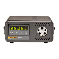
Universal Calibration System
Brand: Fluke
|
Category: Test Equipment
|
Size: 1.02 MB
Table of Contents
-
Table of Contents
4
-
Retrieval of Device Status Information
7
-
About Section 6
7
-
6.2 Index of IEEE-488.2 and SCPI Codes Used in the 9100
10
-
Introduction
10
-
Interface Capability
10
-
Interconnections
12
-
SCPI Programming Language
13
-
Using the 9100 in a System
14
-
Addressing the 9100
14
-
Final Width = 215Mm
15
-
Operation Via the IEEE-488 Interface
16
-
Message Exchange
18
-
Request Service (RQS)
20
-
-
Final Width = 215Mm
21
-
General
21
-
-
Retrieval of Device Status Information
21
-
Section 6: 9100 System Operation — Scpi Language
22
-
IEEE-488 and SCPI Standard-Defined Features
23
-
9100 Status Reporting — IEEE-488.2 Basics
24
-
9100 Status Reporting — SCPI Elements
29
-
9100 SCPI Language — Commands and Syntax
30
-
Introduction
30
-
Calibration Subsystem
32
-
Output Subsystem
34
-
Source Subsystem
36
-
Status Subsystem
56
-
System Subsystem
60
-
-
-
Appendix A: IEEE 488.2 Device Documentation Requirements
71
-
Section 6 Appendix A: IEEE 488.2 Device Documentation Requirements
71
-
Section 6 Appendix B: SCPI Conformance Information
77
-
Section 6 Appendix C: IEEE 488.2 Common Commands and Queries Implemented in the Model 9100
77
-
Section 6 Appendix D: Model 9100 — Device Settings after *RST
91
-
Section 6 Appendix E: Model 9100 — Device Settings at Power on
95
-
-
Section 7 Model 9100 Specifications
97
-
General
97
-
Options and Associated Products
98
-
DC Voltage Specifications
99
-
AC Voltage Specifications
102
-
DC Current Specifications
104
-
AC Current Specifications
106
-
Resistance Specifications
110
-
Conductance Specifications
111
-
Frequency Function Specifications
112
-
Mark/Period Function Specifications
113
-
7.11 % Duty Cycle Function Specifications
114
-
7.12 Auxiliary Functions — Specifications
115
-
7.13 Capacitance Specifications
116
-
7.14 Thermocouple Temperature Specifications
117
-
RTD Temperature Specifications
118
-
Logic-Pulses Function Specifications
119
-
7.17 Logic-Levels Function Specifications
120
-
7.18 Insulation/Continuity Specifications
121
-
7.19 Power Specifications
123
-
-
Section 8 Model 9100 — Routine Maintenance and Test
133
-
About Section 8
133
-
Routine Maintenance
134
-
Firmware Upgrade
136
-
Model 9100 Test and Selftest
142
-
Printing Selftest Results
158
-
Section 8 Appendix A Error Reporting Subsystem
161
-
About Section 9
167
-
The Need for Verification
167
-
Equipment Requirements
168
-
Interconnections
168
-
Verification Points
169
-
Calculating Absolute Specification Limits
170
-
About Section
173
-
The Model 9100 Calibration Mode
175
-
Introduction
175
-
Mode Selection
176
-
Selection of Calibration Mode
176
-
Final Width = 215Mm
176
-
Calibration Mode
178
-
Special Calibration
179
-
Cold Junction Calibration
182
-
Standard Calibration
186
-
Standard Calibration — Basic Sequences
191
-
Introduction
192
-
Selecting Hardware Configurations
194
-
Selecting Target Calibration Values
195
-
Calibrating the Model 9100 at Target Values
199
-
Front Panel Calibration by Functions
209
-
Introduction
209
-
Summary of Calibration Process
210
-
DC Voltage Calibration
214
-
AC Voltage Calibration
222
-
DC Current Calibration
228
-
AC Current Calibration
236
-
Resistance Calibration
244
-
Capacitance Calibration
253
-
Insulation Resistance Calibration
259
-
10.4.10 Continuity Calibration
265
-
-
Remote Calibration of the Model 9100 Via the IEEE 488 Interface
271
-
Advertisement
Fluke 9100 Series Service Manual (74 pages)
Vector Output I/O Module
Brand: Fluke
|
Category: I/O Systems
|
Size: 6.39 MB
Table of Contents
-
Table of Contents
3
-
1 Introduction and Specifications
9
-
Introduction1
9
-
Specifications
9
-
Theory of Operation
13
-
Vector Output I/O Module Overview
13
-
Input Section Functional Block Diagram
15
-
Output Section Functional Block Diagram
16
-
Input Section Theory of Operation
17
-
Mainframe Addressing of the Module
17
-
Mainframe to Bus Interface Functional Block
17
-
Custom Chip Selection
18
-
Input Section Address Decoding Summary
19
-
Address Decoding Example
20
-
Custom Chip Functional Block
20
-
Clock and Enable Mux Functional Block
21
-
Clock and Enable Mux Operation
21
-
Hot-Bit Decoding Examples
21
-
Bus Interface Timing Diagram
22
-
General Control Latch Functional Block
23
-
Control Register
24
-
Data Comparison Inputs
24
-
Fuse Detection
24
-
-
Clock and Enable Mux Truth Table
24
-
Data Compare Equal Output Pin
25
-
Data Comparison and General Interrupts
25
-
Operation of General Control Latch Block
25
-
I/O Module Control and Interrupt Registers
26
-
Custom Chip Voltage Level Detection
27
-
Connector Code Functional Block
28
-
Input Protection Functional Block
28
-
Output Section Theory of Operation
28
-
Main PCA to Top PCA Interface Functional Block
29
-
Addressing
30
-
Internal Oscillator Control Functional Block
32
-
Output Control Functional Block
32
-
-
U25 Drive Register 2 Bit Description (Write @ $D0X21)
32
-
RAM Select Functional Block
33
-
-
U5 Register Bit Description (Write @ $D0X01)
33
-
Chip Counter Operation
34
-
Signal Polarity/Control Register
34
-
SSLOGIC (Start/Stop Logic) Functional Block
34
-
Drive Clock Selection
35
-
-
U6 Register Bit Description (Write @ $D0X11)
35
-
Handshake Synchronization
36
-
Vector Drive Complete Logic
37
-
Vector Address Functional Block
38
-
Vector Control RAM Functional Block
38
-
Vector Pattern RAM Functional Block
38
-
Loop Control Functional Block
39
-
Capture Clock Functional Block
40
-
Drive Status Functional Block
40
-
Output Protection Functional Block
41
-
-
U25 ID/Status Register Bit Description (Read @ $D0X01)
41
-
-
-
3 Maintenance
45
-
Introduction
45
-
Changing the Vector Output I/O Module Fuse
45
-
Cleaning
46
-
Vector Output I/O Module Self Test
46
-
Disassembly
46
-
Troubleshooting
47
-
General Information
47
-
-
-
4 List of Replaceable Parts
49
-
A1 Main PCA
49
-
A2 Top PCA
49
-
Introduction
51
-
How to Obtain Parts
51
-
Additional Information
52
-
9100A-017 Final Assembly
54
-
-
-
5 Schematic Diagrams
65
-
Figure Title Page
65
-
A1 Main PCA
67
-
A2 Top PCA
69
-
Advertisement
Related Products
-
Fluke 9103
-
Fluke 9102S
-
Fluke 9100S
-
Fluke 9170
-
Fluke 9172
-
Fluke 9173
-
Fluke 9171
-
Fluke 9132
-
Fluke 9132A
-
Fluke Hart Scientific 9101
Fluke Categories
Measuring Instruments
Test Equipment
Multimeter
Thermometer
Laboratory Equipment
More Fluke Manuals
File Specifications:260/260364-9100.pdf file (15 Jun 2023) |
Accompanying Data:
Fluke 9100 I/O Systems, Measuring Instruments PDF User Handbook Manual (Updated: Thursday 15th of June 2023 09:25:30 PM)
Rating: 4.4 (rated by 14 users)
Compatible devices: 975CK, 5700A Series, 373, TS 100, i200, 336, 87V Ex, 820-2.
Recommended Documentation:
User Handbook Manual (Text Version):
(Ocr-Read Summary of Contents of some pages of the Fluke 9100 Document (Main Content), UPD: 15 June 2023)
-
242, 10.4-34 Section 10: Calibrating the Model 9100: AC Current Function Final Width = 215mm Amplitude Frequency Table 10.4.6.3: Auxiliary AC Current Calibration Points Output span Calibration Targets covered by hardware configuration Default Minimum Maximum Default Minimum Maximum 0.000mA to 320.0mA 300.000mA 180.000mA 320.000A 40Hz 35Hz 45Hz (one range) 300.000mA 180.000mA 320.000A 150Hz 140Hz 160Hz 300.000mA 180.000mA 320.000A 1000Hz 900Hz 1100Hz 300.000mA 180.000mA 320.…
-
198, 10.3-8 Section 10: Calibrating the Model 9100: Standard Calibration — Basic Sequences Final Width = 215mm When you have finished calibrating one target value you will be returned to the function screen, from which you can: either calibrate the remaining target values for the selected hardware configuration; or select a new hardware configuration by changing the displayed output value. Before deciding to change from ‘Saved’ calibration target values back to the ‘Def…
-
238, 10.4-30 Section 10: Calibrating the Model 9100: AC Current Function Final Width = 215mm Output span Output Calibration Targets Factor covered by to select Number hardware hardware configuration config. Default Minimum Maximum Default Minimum Maximum 000.000µA 100µA 300.000µA 180.000µA 320.000µA 110.00Hz 10.00Hz 320.00Hz 1 to 300.000µA 180.000µA 320.000µA 3.0000kHz 1.0000kHz 5.000kHz 2 320.000µA 300.000µA 180.000µA 320.000µA 30.000kHz 20.000kHz 30.000kHz 3 …
-
234, 10.4-26 Section 10: Calibrating the Model 9100: DC Current Function Final Width = 215mm Table 10.4.5.3: Auxiliary DC Current Calibration Points Hardware Spans Calibration Targets Default Minimum Maximum 0.000mA to ±320.0mA -300.000mA -320.000mA -180.00mA (one range) +300.000mA +180.000mA +320.000mA ±0.321A to ±3.200A -3.00000A -3.20000A -1.80000A +3.00000A +1.80000A +3.20000A ±3.21 to ±32.00A -10.0000A -10.5000A -7.0000…
-
20, 6-14 Section 6: 9100 System Operation — SCPI Language Final Width = 215mm 6.4.3.5 Outgoing Responses The Response Formatter derives its information from Response Data (being supplied by the Functions and Facilities block) and valid Query Requests. From these it builds Response Message Elements, which are placed as a Response Message into the Output Queue. The Output Queue acts as a store for outgoing messages until they are read over the system b…
-
56, 6-50 Section 6: 9100 System Operation — SCPI Language Final Width = 215mm 6.6.5 STATus Subsystem This subsystem is used to enable bits in the Operation and Questionable Event registers. The Operation and Questionable: Event, Enable and Condition registers can be interrogated to determine their state. For further information regarding the Status structure, refer to Sub-Section 6.5.4. 6.6.5.1 STATus Subsystem Table Keyword Parameter Form Notes STATus :OPERation [:EVENt]? [Q…
-
240, 10.4-32 Section 10: Calibrating the Model 9100: AC Current Function Final Width = 215mm 10.4.6.6 Calibration of Auxiliary AC Current (for Power Option) Calibration Setup 1. Connections For the 320mA range connect the 9100 to the Standards DMM as shown in Fig. 10.4.6.3 opposite. If the DMM has a Remote/Local Guard facility, switch it to Local Guard. For all other ranges connect the 9100 to the Standards DMM as shown in Fig. 10.4.6.4 opposite. If the DMM has a Remot…
-
162, Fluke 9100 8-A2 Appendix A to Section 8: 9100 Maintenance — Error Reporting Subsystem Final Width = 215mm 8.A.2.2 Recoverable Errors 8.A.2.2.1 Type of Errors These consist of Command Errors, Execution Errors, Query Errors and Device-Dependent Errors. Command, Query and Execution Errors are generated due to incorrect remote programming. Device-Dependent Errors can be generated by manual as well as remote operation. Each of the reportable errors is identified by a code number…
-
188, 10.2-14 Section 10: Calibrating the Model 9100: Calibration Mode Final Width = 215mm 10.2.7 Overview of Calibration Operations In general, calibration of each of the 9100’s ‘hardware configurations’ can be broken down into three distinct stages as follows:- 1) Selection of the required ‘hardware configuration’ 2) Selection of two or more ‘target’ values at which this hardware configuration will be calibrated. 3) Determination of the 9100’s ou…
-
206, 10.3-16 Section 10: Calibrating the Model 9100: Standard Calibration — Basic Sequences Final Width = 215mm TODAYS DATE TIME 10.3.6 Exit from Calibration — Cal Date and Cal Due Date Once all calibration has been completed, you will wish to return to normal operation, which requires a short ‘exit’ process. The normal means of exit from Calibration mode is to press the Mode key on the right of the front panel. When you do this, the 9100 will present a …
-
93, Appendix D to Section 6: 9100 System Operation — Device Settings after ∗ RST 6-D3 Final Width = 215mm 6.D.3 ∗RST Settings Related to SCPI Commands Keyword Condition CALibration …………………. Disabled :SECure :PASSword required to enter Calibration mode OUTPut [:STATe] …………………. OFF :COMPensation(?) …………… OFF :ISELection(?) …………….. HIGHi [SOURce] :FUNCtion [:SHAPe](?) …………….. DC…
-
68, 6-62 Section 6: 9100 System Operation — SCPI Language Final Width = 215mm 6.7.5.1 [SOURce]:FREQuency[:CW|FIXed(?) <dnpd> This command sets the frequency of the currently selected waveform. The units of this command are assumed to be Hertz. The CW and FIXed optional parameters are included to keep with the SCPI definition of the frequency command: «The Continuous Wave or FIXed node is used to select a frequency of a non-swept signal…
-
270, 10.4-62 Section 10: Calibrating the Model 9100: Continuity Function Final Width = 215mm 10.4.10.4 Verification of Output Current Display 1. Connect a 1271/1281 or similar long-scale meter between the 9100 and the continuity meter 2. Select the 1A range on the 1271 3. Set the 9100 output to zero ohms 4. Turn the 9100 output ON 5. Press the TEST button on the continuity meter and confirm that the current reading displayed by the 9100 is within 1.5% of the current displayed on the referen…
-
149, Fluke 9100 Section 8: Model 9100 — Routine Maintenance and Test 8-17 Final Width = 215mm TODAYS DATE TIMETODAYS DATE TIME TODAYS DATE TIME 8.3.4.2 Display Memory Checks Pressing the DISPLAY MEMORY key on the ‘Select test’ menu screen transfers to the ‘Memory test.’ screen, and the sequence of tests begins. The test in progress is reported on the screen: The other tests reported are: Performing WALKING ONES test…
-
230, Fluke 9100 10.4-22 Section 10: Calibrating the Model 9100: DC Current Function Final Width = 215mm Output span covered Suitable output to Calibration Targets Factor by hardware configuration select hardware Number configuration Default Minimum Maximum 000.000µAto±320.000µA 100µA 000.000µA -0.080µA 32.000µA1 +190.000µA 180.000µA 320.000µA2 ±0.32001mA to ±3.20000mA 1mA -1.90000mA -3.20000mA -1.80000mA 1 +1.90000mA +1.80000mA +3.20000mA…
-
Fluke 9100 User Manual
-
Fluke 9100 User Guide
-
Fluke 9100 PDF Manual
-
Fluke 9100 Owner’s Manuals
Recommended: Electronic Tennis, 900 Treadmill, VP-W61, AFE504W
Links & Tools
Operating Impressions, Questions and Answers:
Types of Manuals:
The main types of Fluke 9100 instructions:
- User guide — rules of useing and characteristics
- Service manual — repair, diagnostics, maintenance
- Operation manual — description of the main functions of equipment
I/O Systems, Measuring Instruments, Test Equipment Instructions by Fluke:
-
Electronic Control Concepts 890
INSTRUCTION MANUAL MODEL 890 X-RAY DOSE METER / EXPOSURE TIME METER Electronic Control ConceptsPO Box 182, 1160 US Route 50Milford, Ohio 45150-9705 USAPhone: 800-VIP-XRAYFax: 845-247-9028 [email protected] | www.eccxray.comA Division of US Nuclear Corpwww.usnuclearcorp.com …
890 Measuring Instruments, 13
-
Macherey-Nagel NANOCOLOR VIS II
Smart photometryNANOCOLOR® VIS II NANOCOLOR® UV/VIS II Quickstart guideMACHEREY-NAGEL GmbH & Co. KG · Neumann-Neander-Str. 6–8 · 52355 Düren · GermanyFrance:MACHEREY-NAGEL EURLTel.: +33 388 68 22 68Fax: +33 388 51 76 88E-mail: [email protected]:MACHEREY-NAGEL AGTel.: +41 62 388 55 00Fax: +4 …
NANOCOLOR VIS II Laboratory Equipment, 33
-
HEINE GAMMA G5
InstructionsRead these instructions carefully before using the HEINESphygmomanometer and keep them in a safe place for futurereference.Safety InformationRange of applications: HEINE GAMMA G® aneroid sphygmomanometers areexclusively designed for measuring blood pressure at the upper arm or thigh on healthy skin.General …
GAMMA G5 Measuring Instruments, 2
-
LLG pH meter 7
LLG-pH METER 7 Art.No. 6.263 600Thank you very much for purchasing this LLG-pH METER 7. Please read the following instructions carefully and always keep this manual within easy reach.L ABWARE®INSTRUCTION MANUALINSTRUCTION MANUALUK …
pH meter 7 Measuring Instruments, 16
-
Omron H7E
CSM_H7E_-N_DS_E_9_31Self-powered TotalizerNew H7ECompact Economical Totalizer with High VisibilityAvailable with Backlit LCD Display• Large display with 8.6-mm character height.• Includes new models with backlight for improved visibility in dimly lit places. (Requires 24-VDC power supply.)• Black and light-gray c …
H7E Measuring Instruments, 33
-
Enttec S-PLAY
S-PLAY (70092) Visit the ENTTEC website for the latest version. .. USER MANUAL 1 | ID: 4686708 Document Updated: April 2021 S-PLAY – User Manual Record, Edit and Playback up to 32 Universes using Art-Net/sACN or 2 Universes using the two built in DMX ports with an all-in-one show recorder. ENTTEC� …
S-PLAY Measuring Instruments, 57
-
Page 1
ANDBOOK Model 9100 Universal Calibration System Volume 2 — Performance Final Width = 215mm… -
Page 2
(for Introduction, Installation, Controls (with Tutorial), Manual Mode and Procedure Mode refer to Volume 1 — Operation) (for Options 250 and 600 refer to Volume 3 — Operation and Performance) ISO 9002 © 2007 Fluke Corporation. All rights reserved. All product names are trademarks of their respective companies. -
Page 3
However, noisy or intense electromagnetic fields in the vicinity of the equipment can disturb the measurement circuit. Users should exercise caution and use appropriate connection and cabling configurations to avoid misleading results when making precision measurements in the presence of electromagnetic interference. © 2007 Fluke Corporation P/N 850301 Issue 11.0 (July 2007) -
Page 4: Table Of Contents
Implemented in the Model 9100 ……….. 6-C1 Section 6 Appendix D: Model 9100 — Device Settings after *RST ……6-D1 Section 6 Appendix E: Model 9100 — Device Settings at Power On ……. 6-E1 Section 7 Model 9100 Specifications General ………………….7-1 Options and Associated Products …………..
-
Page 5
10.4.9 Insulation Resistance Calibration …………10.4-51 10.4.10 Continuity Calibration ……………. 10.4-57 10.5 Remote Calibration of the Model 9100 via the IEEE 488 Interface ….10.5-1 10.5.1 The Model 4950 MTS System …………10.5-1 Model 9100 User’s Handbook — Contents List… -
Page 6
Maximum Output Voltages and Currents. sure safe Unless that it is to do so, DO NOT TOUCH ANY of the following: Model 9100: I+ I- Hi Lo sHi SLo leads terminals Model 9105: H sH sL L +20 leads DANGER… -
Page 7: About Section 6
IEEE-488.1 remote interface. In Section 6 we shall show how the 9100 adopts the IEEE-488.2 message-exchange model and reporting structure, and define the SCPI commands and syntax used to control the 9100. Section 6 is divided into the following sub-sections: page: Index of IEEE-488.2 and SCPI Codes used in the 9100 …….
-
Page 8
Index of IEEE 488.2 and SCPI Codes used in the 9100 6.2.1 Common IEEE 488.2 Commands and Queries Program Coding Description Appendix C, Page: Clears event registers and queues (not O/P queue) 6-C1 ESE Nrf Enables standard-defined event bits 6-C2… -
Page 9
6.2.2 9100 SCPI Subsystems CALibration Used to calibrate the functions and hardware ranges of the 9100, correcting for system errors which have accumulated due to drift and ageing effects: ……………………6-25 SECure :PASSword. Gains access to Calibration operations, using ‘Cal Enable’ switch and Password. -
Page 10: Introduction
Introduction This first part of Section 5 gives the information necessary to put the 9100 into operation on the IEEE 488 bus. For more detailed information, refer to the standard specification in the publications ANSI/IEEE Std. 488.1-1987 and IEEE Std. 488.2-1988.
-
Page 11
9100, is given in Sub-Section 6.4.1. The 9100 has a single primary address, which can be set by the user to any value within the range from 0 to 30 inclusive. It cannot be made to respond to any address outside this range. -
Page 12: Interconnections
Not Ready For Data NDAC Not Data Accepted Interface Clear Service Request Attention SHIELD Screening on cable (connected to 9100 safety ground) DIO 5 Data Input/Output Line 5 DIO 6 Data Input/Output Line 6 DIO 7 Data Input/Output Line 7…
-
Page 13: Scpi Programming Language
SCPI commands are easy to learn, self-explanatory and account for a wide variety of usage skills. A summary of the 9100 commands is given on pages 6-2 and 6-3. The full range of 9100 commands, with their actions and meanings in the 9100, is detailed in alphabetical order in Sub-Section 6-6.
-
Page 14: Using The 9100 In A System
The bus address is one of the ‘MORE’ parameters. By trying to select ‘MORE’, the ‘Configuration’ password will be required. Press the MORE screen key on the right of the bottom row. The 9100 will transfer to the ‘Password Entry’ screen.
-
Page 15: Final Width = 215Mm
Bus address = in the controller program to activate The 9100 IEEE-488 bus address can be set the 9100. The 9100 is always aware of to any number within the range 0 to 30.
-
Page 16: Operation Via The Ieee-488 Interface
6.4.2.2 Operating Conditions When the 9100 is operating under the direction of the application program, there are two main conditions, depending on whether the application program has set the ‘REN’ management line ‘true’ or ‘false’: 1.
-
Page 17
Bus initialization; DCL Message exchange initialization; Final Width = 215mm RST Device initialization. The effects of the RST command are described in Appendix C to this section. Section 6: 9100 System Operation — SCPI Language 6-11… -
Page 18: Message Exchange
However, because each of the types of errors flagged in the Event Status Register is related to a particular stage in the process, a simplified 9100 interface model can provide helpful background. This is shown below in Fig.
-
Page 19
6.4.3.2 9100 STATUS Subsystem Input/Output Control transfers messages from the 9100 output queue to the system bus; and conversely from the bus to either the input buffer, or other predetermined destinations within the device interface. It receives the Status Byte from the status reporting system, as well as the state of the Request Service bit which it imposes on bit 6 of the Status Byte response. -
Page 20: Request Service (Rqs)
Interrupted, Unterminated or Deadlocked condition: Refer to ‘Bit 2’ in paras 6.5.3.5. The Standard document defines the 9100’s response, part of which is to set true bit 2 (QYE) of the Standard-defined Event Status register.
-
Page 21: Retrieval Of Device Status Information
So any assistance which can be given in closing the information loop must benefit both program compilation and subsequent use. Such information is given in the following pages. Final Width = 215mm Section 6: 9100 System Operation — SCPI Language 6-15…
-
Page 22: Section 6: 9100 System Operation — Scpi Language
Output Operation Complete bit 0 Queue the Output Queue) QUEStionable: ESR? ESE? ENABle ? QUEStionable: QUEStionable: EVENt ? ENABle <DNPD> ESE phs Nrf Fig. 6.2 9100 Status Reporting Structure 6-16 Section 6: 9100 System Operation — SCPI Language…
-
Page 23: Ieee-488 And Scpi Standard-Defined Features
Byte also to be set true. If this bit is enabled, then the Status RQS false again, MSS remaining true), and which of the Byte bit 6 (MSS/RQS) will be set true, and the 9100 will set summary bits is true. The STB? command is an equivalent the IEEE-488 bus SRQ line true.
-
Page 24: 9100 Status Reporting — Ieee-488.2 Basics
(QSR), whose bits represent SCPI-defined and device-dependent conditions in the 9100. The QSS bit is true when the data in the QSR contains one or more enabled bits which are true; or false when all the enabled bits in the byte are false. The QSR and its data are defined by the SCPI Standard;…
-
Page 25
Bit 6 (DIO7) is the Master Status Summary Message (MSS bit), and is set true if one of the bits 0 to 5 or bit 7 is true (bits 0, 1 and 2 are always false in the 9100). Bit 7 (DIO4) SCPI-defined Operation Status Summary Bit (QSS) Summarizes the state of the ‘Operation Status data’, held in the ‘Operation Status register’… -
Page 26
This bit is true only if OPC has been programmed and all selected pending operations ERRor? will read successive Device- are complete. As the 9100 operates in serial mode, its usefulness is limited to registering Dependent, Command and Execution the completion of long operations, such as self-test. -
Page 27
This bit is not used in the 9100. It is always set false. Bit 7 9100 Power Supply On (PON) This bit is set true only when the Line Power has just been switched on to the 9100, the subsequent Power-up Selftest has been completed successfully, and the 9100 defaults into Manual mode at Power-on. -
Page 28
6.5.3.7 The Error Queue As errors in the 9100 are detected, they are placed in a ‘first in, first out’ queue, called the ‘Error Queue’. This queue conforms to the format described in the SCPI Command Reference (Volume 2) Chapter 19, para 19.7, although errors only are detected. Three… -
Page 29: 9100 Status Reporting — Scpi Elements
9100 Status Reporting — SCPI Elements 6.5.4.1 General In addition to IEEE 488.2 status reporting the 9100 implements the Operation and Questionable Status registers with associated ‘Condition’, ‘Event’ and ‘Enable’ commands. The extra status deals with current operation of the instrument and the quality of operations.
-
Page 30: 9100 Scpi Language — Commands And Syntax
Square brackets ( [ ] ) are used to enclose a keyword that is optional when programming the command; that is, the 9100 will process the command to have the same effect whether the optional node is omitted by the programmer or not.
-
Page 31
Before any calibration can take place, two security levels must be set. First, there is a switch on the 9100 itself that must be set to CAL ENABLE. Having done this, the calibration password command must be sent. -
Page 32: Calibration Subsystem
1 is required, at a voltage of 29.001V and a frequency of 1.05kHz. Once a target has been set, the 9100 adjustment is restricted to values within the selected hardware voltage span and frequency band.
-
Page 33
This is the remote equivalent of the manual calibration of the pod detailed in Section 10, paras 10.2.5. Identification of the association of the pod with a particular host 9100 unit should be recorded as for the manual case (paras 10.2.5.7) Response If the calibration operation is a success then the command returns a ‘0’. -
Page 34: Output Subsystem
6.6.3 OUTPut Subsystem This subsystem is used to select the output connections of the 9100, switch the output on and off, and switch the lead compensation on and off. 6.6.3.1 OUTPut Subsystem Table Keyword Parameter Form Notes OUTPut [:STATe](?) <CPD>{ON|OFF|0|1} :COMPensation(?) <CPD>{ON|OFF|0|1}…
-
Page 35
(3.2A to 200A) into the 10-turn current coil. switches current outputs via J109 pin 8. OUTP:ISEL LOW Response to Query Version The 9100 will return HIGH/HI50/HI10/LOW to match the active programming parameter. Final Width = 215mm Section 6: 9100 System Operation — SCPI Language 6-29… -
Page 36: Source Subsystem
6.6.4 SOURce Subsystem This subsystem is used to select the sources of 9100 output . 6.6.4.1 SOURce Subsystem Table Keyword Parameter Form Notes [SOURce] :FUNCtion [:SHAPe](?) <CPD>{DC|SINusoid|PULSe|SQUare|IMPulse|TRIangle|TRAPezoid|SYMSquare} :VOLTage [:LEVEl] [:IMMediate] [:AMPLitude](?) <DNPD> :HIGH(?) <DNPD> :LOW(?) <DNPD> :CURRent [:LEVEl] [:IMMediate] [:AMPLitude](?) <DNPD>…
-
Page 37
;: separator. This does not mean that valid short-cut ‘program message unit’ separators cannot be used, but merely that we are defining the commands in full, to avoid confusion. Section 6: 9100 System Operation — SCPI Language 6-31… -
Page 38
Purpose Defines the waveshape of the required output. In certain cases this also steers the 9100 towards the required source. This is necessary to select a 9100 source in a particular group, if the present 9100 source lies outside that group. -
Page 39
Response to Query Version The 9100 will return the appropriate <CPD> from the selection {DC|SIN|PULS|SQU|IMP|TRI|TRAP|SYMS} which represents the present source ‘shape’. If the 9100 is programmed in one of the impedance functions (Group 1 in the table), then it will return NONE. -
Page 40
The ‘decimal numeric program data’ is a number which sets the required output voltage, expressed in units of DC or RMS AC Volts. It will automatically choose the ‘best’ hardware range for the defined voltage output. The 9100 will accept signed or unsigned positive values for DC Voltage. -
Page 41
The value of <DNPD> cannot be equal to or more positive than that sent as the <DNPD> with the corresponding VOLT:HIGH command for the same waveshape. The 9100 will accept signed or unsigned positive values. For details of local operation and parameter limitations, refer to Volume 1, Section 4, Sub-Sections 4.9 (Frequency), 4.10 (Mark/ Period), 4.11 (% Duty Cycle) or 4.16 (Logic Pulses). -
Page 42
The ‘decimal numeric program data’ is a number which sets the required output current, expressed in units of DC or RMS AC Amps. It will automatically choose the ‘best’ hardware range for the defined current output. The 9100 will accept signed or unsigned positive values for DC Current. -
Page 43
Purpose In the synthesized resistance technology used in the 9100, the current sourced from the UUT must fall within certain spans of values for each commanded resistance value. For UUTs producing source currents which are larger than the values in the ‘Low’ (default) Final Width = 215mm span, the greater current can be accommodated by selecting ‘HIGH’ or ‘SUPER’. -
Page 44
Purpose In the synthesized conductance technology used in the 9100, the current sourced from the UUT must fall within certain spans of values for each commanded conductance value. For UUTs producing source currents which are larger than the values in the ‘Low’ Final Width = 215mm (default) span, the greater current can be accommodated by selecting ‘HIGH’ or ‘SUPER’. -
Page 45
Purpose In the synthesized capacitance technology used in the 9100, the current sourced from the UUT must fall within certain spans of values for each commanded capacitance value. For UUTs producing source currents which are larger than the values in the ‘Low’ Final Width = 215mm (default) span, the greater current can be accommodated by selecting ‘SUPER’. -
Page 46
If in AC Voltage or AC Current Function, a sinewave frequency is returned by the query: FREQ? If in ‘Hz’ (Frequency) Function, the squarewave frequency is returned by the query: FREQ? 6-40 Section 6: 9100 System Operation — SCPI Language… -
Page 47
6.6.4.14 [SOUR]:PHAS[:ADJust](?) <DNPD> Purpose This command is used to set the phase angle of the 9100 output, with respect to ‘Phase Lock In’, when operating in either ‘AC Voltage’ or ‘AC Current’ function. <DNPD> The ‘decimal numeric program data’ is a number which sets the required phase angle of the selected operation, expressed in units of Degrees. -
Page 48
[SOUR]:PHAS:OUTP[:STATe](?) <CPD>{OFF|ON|0|1} Purpose The 9100 AC Voltage or AC Current output phase can be used as a reference-phase output via the ‘PHASE LOCK OUT’ plug on the rear panel. This command switches the reference phase on or off. <CPD> The ‘character program data’ switches the 9100: either to output the reference phase (ON or 1); or not (OFF or 0). -
Page 49
If in ‘Mark/Period’ or ‘Logic Pulses’ Function, the squarewave pulsewidth is returned by the query: PULS:WID? If in ‘% Duty Cycle’ Function, the squarewave duty cycle percentage is returned by the query: PULS:DCYC? Section 6: 9100 System Operation — SCPI Language 6-43… -
Page 50
This command affects the values of subsequently programmed temperature. This is clearly demonstrated by the following examples: 1. A 9100 unit is already programmed to simulate a thermocouple at 200 C (Celsius). To simulate 300 C, it is necessary only to send the value command: TEMP:THER 300. -
Page 51
6.6.4.19 [SOUR]:TEMP:SCAL(?) <CPD>{TS68|TS90} Purpose The 9100 supports two types of temperature scale: IPTS-68 (default) and ITS-90. This command determines which of the two temperature scales will be used for subsequently programmed temperature. <CPD> The ‘character program data’ selects the type of scale: TS68 For subsequent commands TEMP:THER <DNPD>… -
Page 52
The ‘decimal numeric program data’ is a number which sets the required temperature value. It must be expressed as a value relating to the units (degrees Celsius, Degrees Fahrenheit, or Kelvin), already set into the 9100 by the most-recent TEMP:UNIT <CPD>… -
Page 53
The ‘decimal numeric program data’ is a number which sets the required temperature value. It must be expressed as a value relating to the units (degrees Celsius, Degrees Fahrenheit, or Kelvin), already set into the 9100 by the most-recent TEMP:UNIT <CPD>… -
Page 54
Purpose In the synthesized resistance technology used for RTD simulation in the 9100, the current sourced from the UUT must fall within certain spans of values for each commanded temperature value. For UUTs producing source currents which are larger than the values in the ‘Low’ (default) span, the greater current can be accommodated by selecting ‘HIGH’ or ‘SUPER’. -
Page 55
Note 1 : If the commands :CONT:TCUR? , :INS:TVOL? or :INS:TCUR? are executed when the output is OFF, or the Model 9100 is not in the relevant function, the value returned will be 2.0E+35 . Section 6: 9100 System Operation — SCPI Language… -
Page 56: Status Subsystem
For example (refer to Fig. 6.2): If the 9100 had just performed a selftest, the ‘TESTING’ bit 8 of the register would be set, and if no other Operation Event bits were enabled, the number 256 would be returned. Bit 8 (indeed, all bits in the register) would be reset by this query.
-
Page 57
Operation Condition register bits to determine their current status. For example (refer to Fig. 6.2): If the 9100 was in the process of performing a selftest, only the ‘TESTING’ bit 8 of the register would be temporarily set, and the number 256 would be returned. -
Page 58
Questionable Enable mask. For example (refer to Fig. 6.2): If the ‘INV OHM CURR1’ bit 9 of the register is the only enabled bit, the number 512 would be returned. 6-52 Section 6: 9100 System Operation — SCPI Language… -
Page 59
SRQ; providing only that bits 3 and 7 in the IEEE-488.2 Status Byte Register are also enabled. The use of PRES in the 9100 allows the status-reporting structure to be set to a known state, not only for the intention of the SCPI mandate, but also to provide a known starting point for application programmers. -
Page 60: System Subsystem
The Error Queue As errors in the 9100 are detected, they are placed in a ‘first in, first out’ queue, called the ‘Error Queue’. This queue conforms to the format described in the SCPI Command Reference (Volume 2), although errors only are detected. Three kinds of errors are…
-
Page 61
N.B. A password is required for access to change the date format. Refer to Volume 1 of this User’s Handbook; Section 3, Subsection 3.3.2, paras 3.3.2.2 and 3.3.2.10. Purpose This command is not used to change the date format. It only changes the present date, as recognized by the 9100, within the current date format, as defined locally. <SPD>… -
Page 62
SYST:TIME(?) <SPD> Purpose This command changes the present time as recorded by the 9100 software. Any new time will be updated from a non-volatile real- time internal 24-hour clock. <SPD> This string defines the present time, consisting of two 2-digit numbers, separated by a hyphen. The numbers represent hour and minute, in that order. -
Page 63
This command sets the voltage value of the threshold of operation for the High Voltage Warning as employed in DC Voltage and AC Voltage functions. The 9100 need not be currently set in either of these functions to program the voltage. -
Page 64
OUTPut[:STATe](?)<cpd>{OFF|ON|0|1} This command will connect the output signal to the Main (hi/lo) and Auxiliary (I+/I-) channels. • This command behaves in the same manner as described in the 9100 manual. It is included in this document for completeness only. 6.7.2.2 OUTPut:ISELection(?) <cpd>{HIGHi|HI50turn|HI10turn|LOWi}… -
Page 65
Selecting any of the other waveshapes will select AC power and default the other channel waveshape to SIN. • If a waveform is selected for whom the present amplitude is to large, then a settings conflict will be reported. Section 6: 9100 System Operation — SCPI Language 6-59… -
Page 66
This command determines the scale factor applied to the auxiliary channel, when in ‘auxiliary voltage’ mode, to calculate the effective voltage on the auxiliary channel: VOUT aux =I aux *Scale • This is equivalent to the scale value set in the manual configuration screen. 6-60 Section 6: 9100 System Operation — SCPI Language… -
Page 67
• If the instrument is not in harmonics, then a settings conflict error will be generated. • The range of the PANGle<dnpd> is +180.0 to -180.0. Values outside this will generate a Data out of range error. Section 6: 9100 System Operation — SCPI Language 6-61… -
Page 68
[SOURce]:PHASe[:ADJust(?) <dnpd> This command is used to set the phase angle of the 9100 output, with respect to ‘Phase Lock In’, when operation in either AC Voltage, Current or Power functions. • The range of the <dnpd> is +180.0 to -180.0. Values outside this will generate a Data out of range error. -
Page 69
600 (600 MHz scope option). where x4 indicates option 135 (High voltage resistance option). where x5 indicates option PWR (Power option). where x6 is reserved for future use. Section 6: 9100 System Operation — SCPI Language 6-63… -
Page 71: Section 6 Appendix A: Ieee 488.2 Device Documentation Requirements
PRT and UNIT and TYPE the 9100 recognizes a user-initiated address change. Appendix E to Section 6 describes the active and non- active settings at power-on. Appendix A to Section 6: 9100 System Operation — IEEE 488.2 Device Documentation Requirements 6-A1…
-
Page 72
They are also described in Section 6, Appendix C completed. 24. No representations are used for ‘Infinity’ and ‘Not-a- CAL? is not implemented. Number’. DDT is not implemented. 6-A2 Appendix A to Section 6: 9100 System Operation — IEEE 488.2 Device Documentation Requirements… -
Page 73
The instrument complies with the version 1994. The Confirmed Query: SYSTem:VERSion? will return this version number. Syntax of All SCPI Commands and Queries Implemented in the Model 9100 All the Commands and Queries are present, each annotated with the state of its SCPI approval. -
Page 74
…………….Not SCPI Approved [:AMPLitude](?) <DNPD> …………….Not SCPI Approved :TYPE(?) <CPD>{PT385|PT392} …………….Not SCPI Approved :NRESistance(?) <DNPD> …………….Not SCPI Approved :UUT_I(?) <CPD>{LOW|HIGH|SUPer} …………….Not SCPI Approved 6-B2 Appendix B to Section 6: 9100 System Operation — SCPI Documentation Requirements… -
Page 75
:TIME(?)<SPD> …………….Not SCPI Approved :SVOLtage(?) <DNPD> …………….Not SCPI Approved :VERSion? [Query Only] …………Confirmed :FORmat? [Query Only] …………Not SCPI Approved Final Width = 215mm Appendix B to Section 6: 9100 System Operation — SCPI Documentation Requirements 6-B3… -
Page 77: Section 6 Appendix C: Ieee 488.2 Common Commands And Queries Implemented In The Model 9100
Power On and Reset Conditions immediately follows a ‘Program Message Terminator’; refer to the IEEE 488.2 standard document. Not applicable. Final Width = 215mm Appendix C to Section 6: 9100 System Operation — IEEE 488.2 Common Commands and Queries 6-C1…
-
Page 78
Reset has no effect. service request byte, for this data structure. The detailed definition is contained in the IEEE 488.2 document. 6-C2 Appendix C to Section 6: 9100 System Operation — IEEE 488.2 Common Commands and Queries… -
Page 79
The value returned, when converted to base 2 (binary), identifies Refer to Section 6; Subsection 6.5. the bits as defined in the IEEE 488.2 standard. Execution Errors: None Final Width = 215mm Appendix C to Section 6: 9100 System Operation — IEEE 488.2 Common Commands and Queries 6-C3… -
Page 80
The final response in the string will be followed by the terminator: nl = newline with EOI 6-C4 Appendix C to Section 6: 9100 System Operation — IEEE 488.2 Common Commands and Queries… -
Page 81
Final Width = 215mm OPC? Response Decode: The value returned is always 1, which is placed in the output queue when all pending operations are complete. Appendix C to Section 6: 9100 System Operation — IEEE 488.2 Common Commands and Queries 6-C5… -
Page 82
Execution Errors: The data element type is Nr1 as defined in the IEEE 488.2 None. standard specification. Power On and Reset Conditions Not applicable. 6-C6 Appendix C to Section 6: 9100 System Operation — IEEE 488.2 Common Commands and Queries… -
Page 83
SRQ on power up. Appendix C to Section 6: 9100 System Operation — IEEE 488.2 Common Commands and Queries 6-C7… -
Page 84
= newline with EOI Power On and Reset Conditions No Change. This data is saved in non-volatile memory at Power Off, for use at Power On. 6-C8 Appendix C to Section 6: 9100 System Operation — IEEE 488.2 Common Commands and Queries… -
Page 85
The data can be recalled using the PUD? query. Power On and Reset Conditions Data area remains unchanged. Appendix C to Section 6: 9100 System Operation — IEEE 488.2 Common Commands and Queries 6-C9… -
Page 86
The final response in the string will be followed by the terminator: nl = newline with EOI 6-C10 Appendix C to Section 6: 9100 System Operation — IEEE 488.2 Common Commands and Queries… -
Page 87
IEEE 488.2 document. Power On and Reset Conditions Note that numbers will be rounded to an integer. Not applicable. Appendix C to Section 6: 9100 System Operation — IEEE 488.2 Common Commands and Queries 6-C11… -
Page 88
For the detail definition see the IEEE 488.2 standard document. There is no method of clearing this byte directly. Its condition relies on the clearing of the overlying status data structure. 6-C12 Appendix C to Section 6: 9100 System Operation — IEEE 488.2 Common Commands and Queries… -
Page 89
Final Width = 215mm detected. indicates operational selftest has failed. The errors can be found only by re-running the self test manually. Refer to Section 8. Appendix C to Section 6: 9100 System Operation — IEEE 488.2 Common Commands and Queries 6-C13… -
Page 90
Power On and Reset Conditions to this instrument as there are no parallel processes requiring Not applicable. Pending Operation Flags. Final Width = 215mm 6-C14 Appendix C to Section 6: 9100 System Operation — IEEE 488.2 Common Commands and Queries… -
Page 91: Section 6 Appendix D: Model 9100 — Device Settings After *Rst
The ‘Enable Macro Command’ ( EMC) is not used in the 9100. The ‘Define Device Trigger Command’ ( DDT) is not used in the 9100. Parallel Poll is not implemented in the 9100. Appendix D to Section 6: 9100 System Operation — Device Settings after RST 6-D1…
-
Page 92
Data area remains unchanged *SRE Nrf Not applicable *SRE? Previous state preserved *STB? Previous state preserved *TST? Not applicable *WAI Not applicable Final Width = 215mm 6-D2 Appendix D to Section 6: 9100 System Operation — Device Settings after RST… -
Page 93
:TEMPerature ….Inactive :UNITs(?) ….C :SCALe(?) ….TS68 :THERmocouple ….Inactive :TYPE(?) ….K :PRT …… Inactive :TYPE(?) ….PT385 :NRESistance(?) ..100 :UUT_I(?) ….LOW Appendix D to Section 6: 9100 System Operation — Device Settings after RST 6-D3… -
Page 95: Section 6 Appendix E: Model 9100 — Device Settings At Power On
Questionable Status Event Register Depends on state of PSC Questionable Status Enable Register Depends on state of PSC Error Queue Empty until first error is detected Appendix E to Section 6: 9100 System Operation — Device Settings at Power On 6-E1…
-
Page 96
:TEMPerature ….Inactive :UNITs(?) ….C :SCALe(?) ….TS68 :THERmocouple ….Inactive :TYPE(?) ….K :PRT …… Inactive :TYPE(?) ….PT385 :NRESistance(?) ..100 :UUT_I(?) ….LOW 6-E2 Appendix E to Section 6: 9100 System Operation — Device Settings at Power On… -
Page 97: Section 7 Model 9100 Specifications
Test Uncertainty Ratio over the instrument ——— under test. 90mA N.B. These specifications apply to both the Model 9100 output terminals and at the remote end of the Model 9105 ——— lead kit unless otherwise stated.
-
Page 98: Options And Associated Products
Option 250 250MHz Oscilloscope Calibrator Module. Option 600 600MHz Oscilloscope Calibrator Module. Line Voltage: The 9100 is configured for use at the correct voltage at the shipment point. 7.2.2 Products Associated with the Model 9100 Final Width = 215mm PLC-XXX Procedure Library Cards (User’s Handbook Section 1, Sub-section 1.4) .
-
Page 99: Dc Voltage Specifications
10% of accuracy: 0.08s Load Regulation: For loads <1M : add (200/R ) % of output LOAD Final Width = 215mm Maximum Capacitance: 1000pF. NOTES: [1] Tcal = temperature at calibration. Factory calibration temperature = 23 C Section 7: Model 9100: Specifications…
-
Page 100
= For loads < |1M |: add load regulation error. † = Availability of voltage and frequency combinations is subject to the Volt-Hertz limit (see V-Hz profile). = 20mA if the Power Option (Option PWR) is fitted. Section 7: Model 9100: Specifications… -
Page 101
1kHz. = If two or more 9100 units are being used in a ‘Master and Slave’ configuration, this specification applies only when both Master and Slave are set to the same frequency. Mark/Space ratio of the input must not be less than 1:4. -
Page 102: Ac Voltage Specifications
452.5V — 866V 0.18 + 120mV = For loads < |1M |: add load regulation error. NOTES: [1] Tcal = temperature at calibration. Factory calibration temperature = 23 C. Frequency Accuracy: 25ppm of output frequency. Section 7: Model 9100: Specifications…
-
Page 103
* • 3E7)] % of output LOAD LOAD LOAD * = To calculate C limit from Current compliance specification, while using 9105 lead set, allow 30pF for lead set. LOAD Maximum Capacitance: 1000pF; subject to Output Current Limitations at HF. Section 7: Model 9100: Specifications… -
Page 104: Dc Current Specifications
Continuous output >0.525FS will automatically reduce to <0.525FS after 2 Minutes. † = Refers to accuracy at 9100 output terminals. With Option 200 coils connected, then at the output from the coils, add 0.2% of output from coils for uncertainty of coils.
-
Page 105
Above 0.5V, add appropriate compliance error, except for Outputs marked = Refers to accuracy at 9100 output terminals. With Option 200 10 turn coil connected, then at the output from the coil, add 0.2% of output from coil for uncertainty of coil. -
Page 106: Ac Current Specifications
1kHz. = If two or more 9100 units are being used in a ‘Master and Slave’ configuration, this specification applies only when both Master and Slave are set to the same frequency. Mark/Space ratio of the input must not be less than 1:4.
-
Page 107
Above 0.5V, add appropriate compliance error, except for Outputs marked = Refers to accuracy at 9100 output terminals. With Option 200 10 turn coil connected, then at the output from the coil, add 0.2% of output from coil for uncertainty of coil. -
Page 108
Above 0.5V, add appropriate compliance error, except for Outputs marked = Refers to accuracy at 9100 output terminals. With Option 200 10 turn coil connected, then at the output from the coil, add 0.2% of output from coil for uncertainty of coil. -
Page 109
2.5 H (With 10 turn or 50 turn output selected): 3.2A — 1000A : 700 H NOTES: [1] Tcal = temperature at calibration. Factory calibration temperature = 23 C. Frequency Accuracy: 25ppm of output frequency. Section 7: Model 9100: Specifications 7-13… -
Page 110: Resistance Specifications
<0.08s — 4M <0.3s — 400M : <1s 4-wire Lead Compensation: Max total lead resistance : Nominal lead resistance rejection: 10000:1 NOTES: [1] Tcal = temperature at calibration. Factory calibration temperature = 23 C 7-14 Section 7: Model 9100: Specifications…
-
Page 111: Conductance Specifications
250nS — 25 S <0.3s 25 S — 2.5mS : <0.08s 4-wire Lead Compensation: Max total lead resistance : Nominal lead resistance rejection: 10000:1 NOTES: [1] Tcal = temperature at calibration. Factory calibration temperature = 23 C Section 7: Model 9100: Specifications 7-15…
-
Page 112: Frequency Function Specifications
(Specified into loads R > 100k in parallel with C 100pF) For signals 6Vpk: <40ns. For signals > 6Vpk: <1.5 s. NOTES: [1] Tcal = temperature at calibration. Factory calibration temperature = 23 C 7-16 Section 7: Model 9100: Specifications…
-
Page 113: Mark/Period Function Specifications
(Specified into loads R > 100k in parallel with C 100pF) For signals 6Vpk: <40ns. For signals > 6Vpk: <1.5 s. NOTES: [1] Tcal = temperature at calibration. Factory calibration temperature = 23 C Section 7: Model 9100: Specifications 7-17…
-
Page 114: 7.11 % Duty Cycle Function Specifications
Duty Cycle is a derived (relative) quantity which describes the Pulse Width / Repetition Period ratio of a pulsed waveform. In the 9100, it is expressed as a percentage. The values of Pulse Width and Repetition Period will change with frequency, while maintaining the same percentage ratio.
-
Page 115: 7.12 Auxiliary Functions — Specifications
Their specifications appear in the following sub-sections: 7.13 ..Capacitance Function Specifications 7.14 ..Thermocouple Temperature Function Specifications 7.15 ..RTD Temperature Function Specifications 7.16 ..Logic Pulses Function Specifications 7.17 ..Logic Levels Function Specifications Section 7: Model 9100: Specifications 7-19…
-
Page 116: 7.13 Capacitance Specifications
2.0 + 120 F 1.0 + 60 F 2.0 + 120 F * = Accuracy specifications apply both at the 9100 output terminals, and at the output leads of the Model 9105 leadset. 7.13.2 Measurement and Discharge Current Final Width = 215mm…
-
Page 117: 7.14 Thermocouple Temperature Specifications
7.14 Thermocouple Temperature Specifications 7.14.1 Temperature Accuracy (Temperature scales selectable between IPTS-68 and ITS-90) NOTE: To calculate the Model 9100’s accuracy in F (Fahrenheit) Thermo- Temperature Output Accuracy * † ‡ or K (Kelvin) proceed as folows:- Couple (Screen Resolution…
-
Page 118: Rtd Temperature Specifications
Settling Time: to within 10% of accuracy : <0.08s 4-wire Lead Compensation: Max total lead resistance : Nominal lead resistance rejection: 10000:1 NOTES: [1] Tcal = temperature at calibration. Factory calibration temperature = 23 C. 7-22 Section 7: Model 9100: Specifications…
-
Page 119: Logic-Pulses Function Specifications
2000.00 ms = Maximum Pulse Width interval must be at least 0.3 s less than that of the set Repetition Period. NOTES: [1] Tcal = temperature at calibration. Factory calibration temperature = 23 C. Section 7: Model 9100: Specifications 7-23…
-
Page 120: 7.17 Logic-Levels Function Specifications
< LOW LVL 0.00V V 1.5V 0.00V Final Width = 215mm High HIGH LVL -0.9V V -1.11V 0.00V Intermediate — — — — — -1.48V -1.11V < < LOW LVL -1.75V V -1.48V -5.20V 7-24 Section 7: Model 9100: Specifications…
-
Page 121: 7.18 Insulation/Continuity Specifications
Maximum Measurement Voltage: 1350VDC: I x R < 1350V Voltage Measurement: Range: 0V to 1350V Final Width = 215mm Accuracy: (0.6% of Output + 1V) Current Measurement: Range: 1 A to 2.3mA Accuracy: 1.5% Section 7: Model 9100: Specifications 7-25…
-
Page 122
400.000 5mA to 70mA 0.40001 k to 4.00000 k 500 A to 7mA Final Width = 215mm 7.18.5 Other Continuity Resistance Specifications Maximum Measurement Voltage: Current Measurement: Range: 100 A to 350mA Accuracy: 7-26 Section 7: Model 9100: Specifications… -
Page 123: 7.19 Power Specifications
The following specifications refer to the Voltage and Current outputs available from the Auxiliary channel — i.e. the I+ and I- outputs of the Model 9100 when the Power function is active. They should not be confused with the normal Voltage and Current output specifications.
-
Page 124
Also directly available as a voltage harmonic output. When used as a harmonic with n>1, add 0.04% to percentage of output specifications. 7.19.5 Other Voltage Waveshapes All subject to 65Hz/1kHz maximum as defined in main Model 9100 specification tables. Note that all waveshapes are specified to 4.525 pk only (4 ranges; equivalent to the 3.2V sinewave range peak). -
Page 125
Performance above 1kHz not specified to user; nominally Gain is as 9100 and Floors as above. All other specifications as 9100 except that the 0.2% adder for the Option 200 coils has been included in the table above. Also directly available as a voltage harmonic output. When used as a harmonic with n>1, add 0.04% to percentage of output specifications. -
Page 126
To obtain the Output Phase Uncertainty with respect to PHASE LOCK OUT or PHASE LOCK IN when operating in POWER mode, add 0.07 . With the 10-turn or 50-turn coil output selected (Option 200). 7-30 Section 7: Model 9100: Specifications… -
Page 127
0.016% = 0.096% 3. Amplitude Uncertainty due to Phase Error (From Section 7.19.9) Specifications: Voltage Channel Phase Uncertainty 0.07 Current Channel Phase Uncertainty 0.08 Combined Phase Uncertainty Ø = 0.07 0.08 ERROR = 0.15 Section 7: Model 9100: Specifications 7-31… -
Page 128
= 0.04% (6.3mV/100V) x 100 = 0.04% 0.0063% = 0.0463% 2. Current Amplitude Uncertainty (From Section 7.19.7) 3A Specification : = 0.08%Rdg 480 A(Floor) = 0.08% (480 A/3A) x 100 = 0.08% 0.016% = 0.096% 7-32 Section 7: Model 9100: Specifications… -
Page 129
= 100 x 1 – Cos (60 + 0.753) Cos 60 = 100 x 1 – 0.488575 = 2.285% The Total Power Uncertainty is therefore the rss of the individual contributions : (0.0463) (0.096) (2.285) = 2.287% Section 7: Model 9100: Specifications 7-33… -
Page 130
0.2037% 0.86 30.00 0.1515% 0.2427% 0.80 36.87 0.1967% 0.3150% 0.70 45.57 0.2674% 0.4282% 0.60 53.13 0.3494% 0.5594% 0.50 60.00 0.4538% 0.7264% 0.25 75.52 1.0141% 1.6229% Final Width = 215mm * For Calibrator output <65Hz 7-34 Section 7: Model 9100: Specifications… -
Page 131
Final Width = 215mm Section 7: Model 9100: Specifications 7-35… -
Page 133: Section 8 Model 9100 — Routine Maintenance And Test
Model 9100 — Routine Maintenance and Test About Section 8 Section 8 gives first-level procedures for maintaining a Model 9100, performing the Selftest operations and dealing with their results. We shall recommend maintenance intervals, methods and parts, and detail the routine maintenance procedures. Section 8 is divided into the following sub-sections: 8.2 Routine Maintenance and Repair.
-
Page 134: Routine Maintenance
2. Release the two screws securing the top cover to the rear panel. 3. Pull the top cover to the rear to clear the front bezel, then lift off to the rear. Section 8: Model 9100 — Routine Maintenance and Test…
-
Page 135
Refit and secure the corner blocks. 8.2.2.7 Replacement Parts Should the filter or snap rivets become damaged by removal or refitting, the following parts can be ordered through your Fluke Sales and Service Center: Part No. Description Manufacturer Type… -
Page 136: Firmware Upgrade
Interface Adaptor’ (PCMCIA). To do this, the Model 9100 has been fitted with FLASH memory chips to provide the update capability. If an upgrade is required for your Model 9100 unit(s), your Service Center will inform you and provide the appropriate PCMCIA card.
-
Page 137
Note any differences between the self tests at items 1 and 6. c. Report the results of the upgrade procedure back to the Service Center. The Model 9100 firmware upgrade is now complete. Please return your PCMCIA to the Service Center. -
Page 138
The I+ and I- Terminal lines are protected by three fuses which protrude through the top guard shield under the top cover. The following paragraphs deal with diagnosing blown output fuses, access and procedures for replacement. 8.2.4.2 Replacement Fuses The following fuses can be ordered through your Fluke Sales and Service Center: Function Part No. Description… -
Page 139
Switch 9100 Power and disconnect the line power lead. b. Lift the left side of the 9100 to stand on its right side. Rotate the instrument to give good access to the small panel (Fig. 8.2.1) on the underside:… -
Page 140
Release the two screws securing the top cover to the Final Width = 215mm and a full recalibration of the 9100 will be required. rear panel. iii. Pull the top cover to the rear to clear the front bezel, d. -
Page 141
Locate the three bayonet fuse holders (Fig. 8.2.3): i. Fit each correct fuse by inserting it into the holder, and carefully push the fuse home. ii. Secure the relevant fuse cap(s) by pushing down and turning clockwise. Section 8: Model 9100 — Routine Maintenance and Test… -
Page 142: Model 9100 Test And Selftest
Test mode is selected from the Mode Selection menu, which is displayed by pressing the front panel ‘Mode’ key, highlighted in Fig 8.3.1, below: Final Width = 215mm OUTPUT — Mode Fig. 8.3.1 ‘Mode’ Key 8-10 Section 8: Model 9100 — Routine Maintenance and Test…
-
Page 143
FULL selftest. INTERFACE allows checks of the display and display memory, the front panel keyboard, the (Procedure mode) memory card slots, the mouse, and the printer interfaces. Continued Overleaf Section 8: Model 9100 — Routine Maintenance and Test 8-11… -
Page 144
Both Fast and Full selftests follow the same format. By pressing the FAST FULL screen key on the ‘ ‘ menu screen, the 9100 runs the selected selftest. Select required test The first screen shows the pathway under test and the number of tests remaining, for the selected selftest: Selftest Selftest. -
Page 145
Test completed with no failures. TODAYS DATE TIME E X I T P R I N T If failures were encountered during the test, the 9100 will display the following screen: Final Width = 215mm Selftest. Selected test has FAILED. Number of failures: XX Use the softkeys to view the results. -
Page 146
N.B. If the cause of failure is not immediately obvious, and it is intended to consult your Fluke Service Center, please ensure that you either: copy the details from the screen for all the reported failures, or: print out the results. No second viewing of the same failure is allowed, although all the test results remain available for printing. -
Page 147
Service Center. The first normal action at power on is to show the Fluke logo, and then the 9100 will run a fast selftest. The user is requested to wait until the selftest is finished: Please wait approx. -
Page 148
8.3.4 Interface Test The interface test selectively checks the 9100 front panel operations, covering display memory integrity, keyboard operation, the display itself, integrity and formatting of static RAM memory cards for Procedure mode, the correct operation of a connected mouse, and the correct operation of a connected printer. -
Page 149
E X I T E X I T If a failure is reported, rectification will require access to the internal circuitry, so no further user action is recommended, except to report the result to your Fluke Service Center. EXIT returns to the Interface ‘ Select test ‘ menu screen. -
Page 150
Rectification will require access to the internal circuitry, so no further user action is recommended, except to report the result to your Fluke Service Center. EXIT returns to the Interface ‘ Select test ‘ menu screen. 8-18 Section 8: Model 9100 — Routine Maintenance and Test… -
Page 151
Rectification will require access to the internal circuitry, so no further user action is recommended, except to report the result to your Fluke Service Center. The ‘… -
Page 152
Results card. It is not possible to format a Procedure card using this test, as procedures are written onto cards by a different process (Fluke Model 9010). 8-20 Section 8: Model 9100 — Routine Maintenance and Test… -
Page 153
The 9100 first checks for the presence of the correct SRAM card. If there is no card in the slot, if the card in the slot is not a SRAM card, or if it is a SRAM card but not write- enabled, then the following screen is displayed: Card slot test. -
Page 154
8.3.4.5 Memory Card Checks (Contd.) The next test is to check the size of the card memory. While the 9100 is checking, it will place the following message on the screen: Card slot test. Checking card size. TODAYS DATE TIME Once the size check is completed, the 9100 starts on a ‘read/write’ check;… -
Page 155
This should narrow the fault down to one slot or one card. If it is suspected that the 9100 is at fault, it is wise to report the result to your Fluke Service Center. -
Page 156
9100, or the same mouse on a different 9100. Rectification may require access to the internal circuitry of the 9100 or mouse, so no further user action is recommended, except to report the result to your Fluke Service Center. -
Page 157
It is possible to diagnose the defect source by checking a second printer unit on the same 9100, or the same printer unit on a different 9100. Rectification may require access to the internal circuitry of the 9100 or printer unit, so no further user action is recommended, except for obvious setup errors. -
Page 158: Printing Selftest Results
Printer is in online state, or connected. AUTO_FEED_L Output Paper is automatically fed 1 line after printing. This line is fixed _H (high) by the 9100 to disable autofeed. ERROR_L Input Printer is in ‘Paper End’, ‘Offline’ or ‘Error’ state.
-
Page 159
-6.553864 -6.553912 gives the achieved percentage of full tolerance for that test. ERROR % In this column a failure is shown by the figure ‘1’ against the relevant test. FAILURES Section 8: Model 9100 — Routine Maintenance and Test 8-27… -
Page 161: Section 8 Appendix A Error Reporting Subsystem
9506 — UNEXPECTED over temperature flag UNDEFINED FATAL ERROR ) An error number will be 9507 — UNEXPECTED HV power supply flag OPERATING SYSTEM ERROR) allocated at run time Appendix A to Section 8: 9100 Maintenance — Error Reporting Subsystem 8-A1…
-
Page 162
-110,»Command header error» -160,»Block data error» -111,»Header separator error» -161,»Invalid block data» -178,»Expression data not allowed» ALWAYS: record the total message content for possible use by the Service Center. 8-A2 Appendix A to Section 8: 9100 Maintenance — Error Reporting Subsystem… -
Page 163
The device is interrupted by a new Program Message before it finishes sending a Response Message. ALWAYS: record the total message content for possible use by the Service Center. Appendix A to Section 8: 9100 Maintenance — Error Reporting Subsystem 8-A3… -
Page 164
-9027,»Down range required» -9058,»Time marker period too small» -9028,»No more ranges» -9059,»Invalid no. of divisions» ALWAYS: record the total message content for possible use by the Service Center. 8-A4 Appendix A to Section 8: 9100 Maintenance — Error Reporting Subsystem… -
Page 165
4058,»Corrupt res. ref. factor» 4006,»Correction block:- invalid» 4059,»Corrupt cold junc diff factor» 4007,»Amplitude outside limits» Continued Overleaf ALWAYS: record the total message content for possible use by the Service Center. Appendix A to Section 8: 9100 Maintenance — Error Reporting Subsystem 8-A5… -
Page 166
-7031,»The transducer scaling factor must 4528,»Limits: PWR DAC linearity» be between 45 uV and 10 mV ALWAYS: record the total message content for possible use by the Service Center. 8-A6 Appendix A to Section 8: 9100 Maintenance — Error Reporting Subsystem… -
Page 167: About Section 9
For users who wish to carry out verification or recalibration of a 9100 on-site, without having to ship the 9100 to a calibration laboratory, the Fluke Model 4950 Multifunction Transfer Standard can be used automatically to calibrate and/or verify the 9100’s accuracy using the PC-based Model 4950 MTS Control Software.
-
Page 168: Equipment Requirements
(the ratio between the accuracy of the 9100 at a verification point and the absolute accuracy of the standard used to verify it at that point) is 3:1, which must apply at all points being used to verify the 9100’s accuracy.
-
Page 169: Verification Points
9100’s outputs, it is beyond the scope of this handbook to define a precise set of verification points for each of the 9100’s functions. However, when selecting verification points the following guidelines should…
-
Page 170: Calculating Absolute Specification Limits
For each chosen verification point it will be necessary to calculate absolute measurement limits which can be used to judge whether or not the 9100 is performing within its specification. As mentioned earlier, the accuracy specifications detailed in Section 7 of this handbook are absolute accuracies which incorporate all the uncertainties involved in calibrating the 9100 up to and including those of National Standards.
-
Page 171
For example, if the 9100’s 2V DC Voltage output was actually 2.0001616V, it would still be within its accuracy specification. However, a voltmeter with a traceable accuracy of 10ppm at 2V could measure this value as 2.0001816V, leading you to believe that the… -
Page 173: About Section
Calibrating the Model 9100 10.1 About Section 10 Section 10 outlines general procedures for calibrating the Model 9100. In it you will find the recommended calibration methods, details of the parameters that require calibration and the procedures needed to calibrate them.
-
Page 175: The Model 9100 Calibration Mode
10.2 The Model 9100 Calibration Mode 10.2.1 Introduction This section is a guide to the use of the Model 9100’s Calibration Mode. The following topics are covered: 10.2.2 Mode Selection 10.2.2.1 ‘Mode’ Key 10.2.2.2 ‘Mode Selection’ Screen 10.2.3 Selection of Calibration Mode 10.2.3.1 Calibration Enable Switch…
-
Page 176: Mode Selection
10.2.2 Mode Selection 10.2.2.1 ‘Mode’ Key Selection of any one of the Model 9100’s five operating ‘Modes’ is enabled by pressing ‘Mode’ key at the bottom right of the ‘CALIBRATION SYSTEM’ key panel. This results in display of the mode selection screen shown below.
-
Page 177
Model 9100’s alphanumeric keyboard. For information about the initial ‘shipment’ password, and about the method of changing this to a custom password, refer to Section 3.3.2.23 of the Model 9100 Universal Calibration System User’s Handbook — Volume 1 — Operation. -
Page 178: Calibration Mode
CALIB automatically by the 9100. This facility permits the monitor circuitry to be calibrated, while in use. The calibration is performed by measuring the temperature of the reference junctions externally, then entering the measured value via the front panel, or remotely via the IEEE-488 bus.
-
Page 179: Special Calibration
Final Width = 215mm Chse—DAC also checks and calibrates the linearity of the Model 9100’s 20-bit D/A converter which is used to set the amplitude of its analog output functions. These adjustments are only required immediately prior to routine Standard Calibration of the Model 9100 as detailed in subsequent sub-sections of this handbook.
-
Page 180
The displayed number ‘n’ represents the current test number. When all Characterise DAC operations are complete (note that the entire process takes around 20 minutes), you will be returned to the Model 9100’s Mode Selection screen. 10.2-6 Section 10: Calibrating the Model 9100: Calibration Mode… -
Page 181
10.2.4.3 ‘Characterise DAC’ Errors If for any reason the Model 9100 is unable to complete one or more of the Characterise DAC operations, error messages similar to that shown below will be displayed and default correction factors will be written to the Model 9100’s non-volatile calibration memory. -
Page 182: Cold Junction Calibration
(‘CJC Pod’), whose internal temperature is monitored automatically by the host 9100. A CJC pod is calibrated for use with a particular host 9100 unit, and is not interchangeable between 9100s unless a recalibration is carried out. The…
-
Page 183
To encourage user organisations to register the association of each pod with a particular 9100, the label affixed to each pod has the serial number of the pod, plus a blank space for recording the serial number of the 9100 with which it is calibrated. -
Page 184
Calibration Mode screen. EXIT 9. CJC Pod Ensure that the correct 9100 serial number is written on the pod identification label. If not, erase the old number and write in the correct number. Also ensure that any other relevant records reflect the 9100/pod association. -
Page 185
4-wire connection. Do not use 2-wire into the Hole in the connection as errors end of the Pod will be excessive. Fig. 10.2.5.1 Setup for Cold Junction Calibration Final Width = 215mm Section 10: Calibrating the Model 9100: Calibration Mode 10.2-11… -
Page 186: Standard Calibration
(they are either derived directly from functions that can be calibrated or are calibrated ‘for life’ during manufacture). Attempting to select these functions while the Model 9100 is in CAL mode will result in an error message being displayed:- No calibration for this function 10.2-12…
-
Page 187
CAL mode, labelled TARGET. In CAL mode, the purpose of the function screens is simply to allow you to set the 9100 into the various ‘hardware configurations’ required during calibration. -
Page 188
10.2.7 Overview of Calibration Operations In general, calibration of each of the 9100’s ‘hardware configurations’ can be broken down into three distinct stages as follows:- 1) Selection of the required ‘hardware configuration’ 2) Selection of two or more ‘target’ values at which this hardware configuration will be calibrated. -
Page 189
DC Voltage AC Voltage Auxiliary Functions Capacitance Functions shaded thus cannot be selected when the Temperature Model 9100 is in CAL mode Logic Fig. 10.2.2 Access to Functions in Calibration Mode Section 10: Calibrating the Model 9100: Calibration Mode 10.2-15… -
Page 191: Standard Calibration — Basic Sequences
10.3 Standard Calibration — Basic Sequences This sub-section describes in more detail the main processes involved when calibrating each of the Model 9100’s ‘hardware configurations’ from the instrument’s front panel. The following topics are covered: 10.3.1 Introduction 10.3.1.1 Aim of Calibration 10.3.1.2 General Calibration Process…
-
Page 192: Introduction
1) Select the required ‘hardware configuration’. 2) Select ‘target’ values at which this hardware configuration will be calibrated. 3) Determine the 9100’s output error at each of these target values, and generate a suitable compensating correction factor. This sub-section 10.3 describes the general process of calibrating the 9100 using front- panel controls.
-
Page 193
C A L Z E R O TODAYS DATE TIME Final Width = 215mm TARGET Section 10: Calibrating the Model 9100: Standard Calibration — Basic Sequences 10.3-3… -
Page 194: Selecting Hardware Configurations
Output control in the ‘Cal’ mode of the function screens is exactly the same as in normal operation of the 9100, being performed either by the digit edit method (cursor controls/ spinwheel), the direct edit method (numeric keypad), or by use of the x10, 10, ZERO softkeys.
-
Page 195: Selecting Target Calibration Values
10.3.3.1 The Target Selection Screen Once the correct hardware configuration has been established by setting the 9100 output control display to a suitable output value, pressing the TARGET softkey will present a ‘target selection’ screen similar to that shown below. This screen shows those target values at which the selected hardware configuration was last calibrated, indicated by the «SAVED CALIBRATION TARGETS»…
-
Page 196
2) use default target points which are pre-programmed into the Model 9100’s firmware — see Section 10.3.3.3. Note that the 9100 also provides you with a third option, which is to change the existing calibration targets to new values. However, this option only becomes available when you move on to the Calibration screen —… -
Page 197
10.3.3.3 Using the Default Calibration Targets As mentioned earlier, the Model 9100’s firmware contains a complete set of recommended target calibration values, for every hardware configuration of every function that can be directly calibrated. If you wish to use these ‘default’ values, rather than the values at which… -
Page 198
3.00000V for the 0.32001V to 3.20000V DC Voltage hardware configuration). Changing the default target values back to 3.00000V may reduce the usefulness of historical calibration records for this 9100 unit, if it normally uses 3.05426V as the target value. -
Page 199: Calibrating The Model 9100 At Target Values
9100 output OFF. If you accidentally press the CALIB key, or attempt a calibration without first turning the 9100 output on, the following error message will be…
-
Page 200
With the cursor on the displayed target value, you can now alter the target value using digit or direct edit employed in normal operation — (Model 9100 Universal Calibration System User’s Handbook, Volume 1, Operation, Section 3, sub-section 3.4). -
Page 201
9100 screen. 3. Press the CALIB (Calibrate) screen key. The 9100 reverts to show a function screen with the displayed output value equal to the Final Width = 215mm target value, and both equal to the externally-measured output value (to within normal measurement errors;… -
Page 202
10.3.4.4 Calibration Errors In stage (2) of the calibration procedure, the output of the 9100 is incremented or decremented by the necessary amount to obtain a measured output equal to the target value. In the process, a condition may arise which prevents generation of a suitable correction factor, due to predefined internal limits for that ‘Factor’ being exceeded. -
Page 203
10.3.5 Standard Calibration of AC Functions Standard calibration of the AC Voltage and AC Current functions in the 9100 uses the same procedure as that described in Sections 10.3.1 to 10.3.4 of this section except that the frequency of the target calibration points must also be set. -
Page 204
You can now alter the frequency setting using the same digit edit (cursor controls/spinwheel) method or direct edit (numeric keypad) method used to change frequency values in normal operation of the Model 9100 — see Section 3.4 of the Model 9100 Universal Calibration System User’s Handbook — Volume 1 — Operation. -
Page 205
You can now continue with the calibration as detailed in Section 10.3.4.3.-stage 2. Final Width = 215mm Section 10: Calibrating the Model 9100: Standard Calibration — Basic Sequences 10.3-15… -
Page 206
Mode key on the right of the front panel. When you do this, the 9100 will present a Warning screen to indicate that the 9100 calibration may have changed, and to offer you the following options: •… -
Page 207
Final Width = 215mm Advance Warning Period In order to inform a user that the future due date for calibration is approaching, the 9100 will place a warning on the screen, starting at a period of time before the due date. During… -
Page 209: Front Panel Calibration By Functions
10.4 Front Panel Calibration by Functions 10.4.1 Introduction Sub-section 10.4 is a guide to the process of calibrating the Model 9100’s functions from the front panel. The following topics are covered: 10.4.2 Summary of Calibration Process 10.4.2.1 General Procedure 10.4.2.2 Sequencing Calibrations 10.4.3…
-
Page 210: Summary Of Calibration Process
10.4.2.1 General Procedure Subsections 10.2 and 10.3 introduced the general calibration process for the Model 9100, described how to select and perform the ‘Characterise DAC’ special calibration operation, and how to calibrate the CJC Pod temperature monitor for the Reference Junction. They also outlined the methods used to select functions, hardware configurations and target calibration points, and how to calibrate the 9100 at these target points.
-
Page 211
Now use any of the 9100’s normal editing modes to change this value. (Note that the new value must lie within the limits specified in the detailed procedures provided later in this section.) -
Page 212
24. Repeat steps (14) to (23) for each of the hardware configurations associated with the 9100 function that is being calibrated (see note * below). 25. Repeat steps (13) to (24) for each function of the 9100 which is being calibrated (see note * below). -
Page 213
10.4.2.2 Sequencing Calibrations The table below indicates the order in which the various Model 9100 functions should be calibrated. Although it is not essential to calibrate all the functions indicated below at any one time, functions higher in the list should be calibrated before those lower in the list. -
Page 214: Dc Voltage Calibration
10.4.3 DC Voltage Calibration 10.4.3.1 Introduction This section is a guide to calibrating the Model 9100’s DC Voltage Function using its front panel controls. The following topics are covered: 10.4.3.2 Calibration Equipment Requirements 10.4.3.3 Interconnections 10.4.3.4 Calibration Setup 10.4.3.5 Calibration Procedure 10.4.3.2…
-
Page 215
10.4.3.3 Interconnections HIGH VOLTAGE DANGER 15Vpk 1500Vpk 15Vpk Final Width = 215mm Coaxial Cable e.g. 1513 Standards DMM Guard Guard Reset Fig 10.4.3.1 DC Voltage Calibration — Interconnections Section 10: Calibrating the Model 9100: DC Voltage Function 10.4-7… -
Page 216
10.4.3.4 Calibration Setup 1. Connections Ensure that the 9100 is connected to the Standards DMM as shown in Fig. 10.4.3.1, and that both instruments are powered on and warmed up. 2. 9100 Ensure that the 9100 is in STANDARD CAL mode and then select the DC Voltage function by pressing the ‘ key on the right of the front panel. -
Page 217
Now use any of the 9100’s normal editing modes to change this value. (Note that the new value must lie within the minimum and maximum limits specified in the tables opposite) 6. -
Page 218
Ensure that the 9100 is connected to the Standards DMM as shown in Fig. 10.4.3.2, and that both instruments are powered on and warmed up. 2. 9100 Ensure that the 9100 is in STANDARD CAL mode and then select Power and DC Volts by pressing the front- panel AUX key followed by the softkey sequence POWER , VOLTAGE. -
Page 219
DANGER HIGH VOLTAGE 15Vpk 1500Vpk 15Vpk Final Width = 215mm Coaxial Cable e.g. 1513 Standards DMM Guard Guard Reset Fig 10.4.3.2 Auxiliary DC Voltage Calibration — Interconnections Section 10: Calibrating the Model 9100: DC Voltage Function 10.4-11… -
Page 220
32.1mV to 320.0mV -300.000mV -320.000mV -180.000mV +300.000mV +180.000mV +320.000mV 0.321V to 3.200V -3.00000V -3.20000V -1.80000V +3.00000V +1.80000V +3.20000V 3.201V to 7.500V -6.00000V -6.50000V -4.00000V +6.00000V +4.00000V +6.50000V Final Width = 215mm 10.4-12 Section 10: Calibrating the Model 9100: DC Voltage Function… -
Page 221
Now use any of the 9100’s normal editing modes to change this value. (Note that the new value must lie within the minimum and maximum limits specified in the tables opposite) 6. -
Page 222: Ac Voltage Calibration
10.4.4 AC Voltage Calibration 10.4.4.1 Introduction This section is a guide to calibrating the Model 9100 AC Voltage Function using its front panel controls. The following topics are covered: 10.4.4.2 Calibration Equipment Requirements 10.4.4.3 Interconnections 10.4.4.4 Calibration Setup 10.4.4.5 Calibration Procedure 10.4.4.2…
-
Page 223
10.4.4.3 Interconnections DANGER HIGH VOLTAGE 15Vpk 1500Vpk 15Vpk Coaxial Cable e.g. 1513 Standards DMM Guard Guard Reset Fig 10.4.4.1 AC Voltage Calibration — Interconnections Section 10: Calibrating the Model 9100: AC Voltage Function 10.4-15… -
Page 224
10.4.4.4 Calibration Setup 1. Connections Ensure that the 9100 is connected to the Standards DMM as shown in Fig. 10.4.4.1, and that both instruments are powered on and warmed up. 2. 9100 a. Ensure that the 9100 is in STANDARD CAL mode and then select the AC Voltage function by pressing the ‘V’ key on the right of the front panel, followed by pressing the ‘ V’ screen key adjacent to the display. -
Page 225
Now use any of the 9100’s normal editing modes to change this value. (Note that the new value must lie within the minimum and maximum limits specified in the tables opposite.) 6. -
Page 226
Ensure that the 9100 is connected to the Standards DMM as shown in Fig. 10.4.3.2, and that both instruments are powered on and warmed up. 2. 9100 Ensure that the 9100 is in STANDARD CAL mode and then select Power and AC Volts by pressing the front- panel AUX key followed by the softkey sequence POWER , VOLTAGE. -
Page 227
Now use any of the 9100’s normal editing modes to change this value. (Note that the new value must lie within the minimum and maximum limits specified in the tables opposite.) 6. -
Page 228: Dc Current Calibration
10.4.5 DC Current Calibration 10.4.5.1 Introduction This section is a guide to calibrating the Model 9100’s DC Current Function using its front panel controls. The following topics are covered: 10.4.5.2 Calibration Equipment Requirements 10.4.5.3 Interconnections 10.4.5.4 Calibration Setup 10.4.5.5 Calibration Procedure 10.4.5.2…
-
Page 229
Keep Coaxials Close Standards DMM Together Standards DMM Guard Guard Guard Guard Reset Reset Fig. 10.4.5.2 DC High Current Calibration — Fig. 10.4.5.1 DC Low Current Calibration — Interconnections Interconnections Section 10: Calibrating the Model 9100: DC Current Function 10.4-21… -
Page 230
Calibration Setup 1. Connections Ensure that the 9100 is connected to the Standards DMM as shown in Fig. 10.4.5.1 or Fig. 10.4.5.2 (depending on the magnitude of current being calibrated), and that both instruments are powered on and warmed up. If the measuring instrument has a switchable signal guarding facility it should be switched to remote guard. -
Page 231
Now use any of the 9100’s normal editing modes to change this value. (Note that the new value must lie within the minimum and maximum limits specified in the tables opposite.) 6. -
Page 232
DMM has a Remote/Local Guard facility, switch it to Local Guard. For all other ranges connect the 9100 to the Standards DMM as shown in Fig. 10.4.5.4 opposite. If the DMM has a Remote/Local Guard facility, it should be switched to Remote Guard when a connection to the shunt’s case can be made. -
Page 233
Coaxial Cable e.g. 1513 Standards DMM Standards DMM Guard Guard Guard Guard Reset Reset Interconnections for calibration points Interconnections for calibration points Fig. 10.4.5.3 Fig. 10.4.5.4 below 1.9A above 1.9A Section 10: Calibrating the Model 9100: DC Current Function 10.4-25… -
Page 234
-300.000mA -320.000mA -180.00mA (one range) +300.000mA +180.000mA +320.000mA 0.321A to 3.200A -3.00000A -3.20000A -1.80000A +3.00000A +1.80000A +3.20000A 3.21 to 32.00A -10.0000A -10.5000A -7.00000A +10.0000A +7.00000A +10.5000A Final Width = 215mm 10.4-26 Section 10: Calibrating the Model 9100: DC Current Function… -
Page 235
Now use any of the 9100’s normal editing modes to change this value. (Note that the new value must lie within the minimum and maximum limits specified in the tables opposite.) 6. -
Page 236: Ac Current Calibration
10.4.6 AC Current Calibration 10.4.6.1 Introduction This section is a guide to calibrating the Model 9100’s AC Current Function using its front panel controls. The following topics are covered: 10.4.6.2 Calibration Equipment Requirements 10.4.6.3 Interconnections 10.4.6.4 Calibration Setup 10.4.6.5 Calibration Procedure 10.4.6.2…
-
Page 237
Keep Coaxials Close Together Standards DMM Standards DMM Guard Guard Guard Guard Reset Reset Interconnections for Low Current Interconnections for High Current Fig. 10.4.6.1 Fig. 10.4.6.2 Outputs (>1A) Outputs ( 1A) Section 10: Calibrating the Model 9100: AC Current Function 10.4-29… -
Page 238
2. 9100 a. Ensure that the 9100 is in STANDARD CAL mode and then select the AC Current function by pressing the ‘A’ key on the right of the front panel, followed by pressing the ‘ A’ screen key adjacent to the display. -
Page 239
Now use any of the 9100’s normal editing modes to change this value. (Note that the new value must lie within the minimum and maximum limits specified in the tables opposite.) 6. -
Page 240
DMM has a Remote/Local Guard facility, switch it to Local Guard. For all other ranges connect the 9100 to the Standards DMM as shown in Fig. 10.4.6.4 opposite. If the DMM has a Remote/Local Guard facility, it should be switched to Remote Guard when a connection to the shunt’s case can be made. -
Page 241
Coaxial Cable e.g. 1513 Standards DMM Standards DMM Guard Guard Guard Guard Reset Reset Fig. 10.4.6.3 320mA Range Calibration — Fig. 10.4.6.4 1A range and Higher Calibration — Interconnections Interconnections Section 10: Calibrating the Model 9100: AC Current Function 10.4-33… -
Page 242
3.21 to 20.00A 10.0000A 7.00000A 10.5000A 40Hz 35Hz 45Hz 10.0000A 7.00000A 10.5000A 150Hz 140Hz 160Hz 10.0000A 7.00000A 10.5000A 1000Hz 900Hz 1100Hz 10.0000A 7.00000A 10.5000A 3000Hz 2700Hz 3000Hz Final Width = 215mm 10.4-34 Section 10: Calibrating the Model 9100: AC Current Function… -
Page 243
Now use any of the 9100’s normal editing modes to change this value. (Note that the new value must lie within the minimum and maximum limits specified in the tables opposite.) 6. -
Page 244: Resistance Calibration
10.4.7 Resistance Calibration 10.4.7.1 Introduction This section is a guide to calibrating the Model 9100’s Resistance Function using its front panel controls. The following topics are covered: 10.4.7.2 Source Currents 10.4.7.3 Target Calibration Points 10.4.7.4 Calibration Equipment Requirements 10.4.7.5 Interconnections 10.4.7.6 Calibration Setup…
-
Page 245
‘UUTi Low’ ‘UUTi High’ and ‘UUTi Super’ source current operating modes. These hardware configurations, and their corresponding ranges of UUTi source currents used during normal operation of the 9100 are shown in Table 10.4.7.1. The 9100 is switched between UUTi source currents by pressing the CHANGE CURRENT screen key. -
Page 246
9100 selected hardware configuration b. allows measurement of the 9100 output to be made at as high a percentage of the calibration equipment’s range as possible. For example, suppose your calibration equipment is a standards laboratory DMM which generates a source current of 10 A on its 1M range and 1 A on its 10 M range. -
Page 247
10.4.7.5 Interconnections Final Width = 215mm Fig. 10.4.7.1 Resistance Calibration — Interconnections Section 10: Calibrating the Model 9100: Resistance Function 10.4-39… -
Page 248
10.4.7.6 Calibration Setup 1. Connections Ensure that the 9100 is connected to the Standards DMM as shown in Fig. 10.4.7.1, and that both instruments are powered on and warmed up. 2. 9100 Select the Resistance Function by pressing the ‘ ‘ key on the right of the front panel. -
Page 249
Now use any of the 9100’s normal editing modes to change this value. (Note that the new value must lie within the minimum and maximum limits specified in the table opposite.) 6. -
Page 250
UUTi High source current hardware configurations have been calibrated. Otherwise the calibration correction factors produced will be overwritten by those generated automatically by the UUTi High source current calibrations. 10.4-42 Section 10: Calibrating the Model 9100: Resistance Function… -
Page 251
5. To change the amplitude of the target calibration point, press the TAB key to position the cursor on the target value amplitude. Now use any of the 9100’s normal editing modes to change this value. (Note that the new value must lie within the minimum Final Width = 215mm and maximum limits specified in the tables opposite.) -
Page 252
The chosen points should be measured using a Fluke 1281, 1271, or 4950. A 1281 (or 1271 within 24 hours of self cal) will usually be preferred by the user for reasons of availability and speed. If it is desired to verify the 10A range, the use of a Fluke 4953 shunt is recommended. -
Page 253: Capacitance Calibration
Capacitance must be calibrated after Resistance to prevent overwriting of the Capacitance function’s calibration correction factors. Due to the cost of maintaining a suitable set of standard capacitors, (2 per 9100 capacitance span), it is not really practicable to use this technique for values above about 400 F.
-
Page 254
15Vpk Set to 4-wire. 1500Vpk Pin 7 15Vpk Final Width = 215mm Safety Bananas Terminated with Probe Adaptors. Capacitance Meter used as transfer K-type device Fig 10.4.8.1 Capacitance Calibration — Interconnections 10.4-46 Section 10: Calibrating the Model 9100: Capacitance Function… -
Page 255
10.4.8.4 Calibration Setup 1. Connections Ensure that the 9100 is connected to the capacitance meter as shown in Fig. 10.4.8.1, and that both instruments are powered on and warmed up. 2. 9100 Ensure that the 9100 is in STANDARD CAL mode and then select the Capacitance function by pressing the ‘ key on the right of the front panel followed by the ‘ ‘ screen key adjacent to the display. -
Page 256
5. If the displayed target value is not the same as the value of your standard capacitor for this calibration point, press the TAB key to position the cursor on the target value and use any of the 9100’s normal editing modes to change the target value to that of the standard capacitor. -
Page 257
80.000 F 190.000 F 250.000 F 390.000 F 0.40001mF to 4.00000mF 0.60000mF 0.41000mF 0.80000mF 1.90000mF 2.50000mF 3.90000mF 4.0001mF to 40.0000mF 10mF 6.0000mF 4.1000mF 8.0000mF 19.0000mF 25.0000mF 39.0000mF Final Width = 215mm Section 10: Calibrating the Model 9100: Capacitance Function 10.4-49… -
Page 258
5. If the displayed target value is not the same as the value of your standard capacitor for this calibration point, press the TAB key to position the cursor on the target value and use any of the 9100’s normal editing modes to change the target value to that of the standard capacitor. -
Page 259: Insulation Resistance Calibration
Due to the high voltages and high resistance values required, it is not practical to calibrate the Option 135 Insulation Resistance function using a standard resistance meter. Special equipment is used at manufacture to calibrate this function of the Model 9100 before shipment.
-
Page 260
(or better) insulation test meter (for example, a Yokogawa 2426). This is used to make transfer measurements between the standard resistors and the Model 9100. Final Width = 215mm 10.4-52 Section 10: Calibrating the Model 9100: Insulation Resistance Function… -
Page 261
10.4.9.3 Interconnections Connect the positive output terminal of the insulation meter to the HI terminal of the 9100 and the negative output terminal of the insulation meter to the LO terminal of the 9100 as shown in Fig. 10.4.9.1 below. -
Page 262
10.4.9.4 Calibration Setup 1. Connections Ensure that the 9100 is connected to the insulation tester as shown in Fig. 10.4.9.1 and that both instruments are powered on and warmed up. 2. 9100 Ensure that the 9100 is in STANDARD CAL mode and then select… -
Page 263
(allow for the settling time of the insulation test meter). 8. Release the TEST button and reconnect the insulation tester to the 9100. 9. Press the ON key to turn the 9100 output on. Press the TEST button on the insulation Final Width = 215mm tester and note the reading. -
Page 264
10.4.9.6 Verification of Output Voltage Display It is not possible to adjust the factors which scale the display of output voltage in the 9100’s Insulation Resistance mode. However, a suitable method of verification is as follows: 1. Connect the insulation tester across the HI and LO terminals of the 9100 as shown in Fig. -
Page 265: 10.4.10 Continuity Calibration
10.4.10 Continuity Calibration 10.4.10.1 Introduction This sub-section is a guide to calibrating the Model 9100’s Continuity function (part of Option 135) using the front panel controls. The following topics are covered in this sub-section: 10.4.10.2 Calibration Equipment Required 10.4.10.3 Interconnections 10.4.10.4 Calibration Setup…
-
Page 266
350mA • digit (or better) continuity test meter (for example a Yokogawa 2426). This is used to make transfer measurements between the standard resistors and the 9100. Final Width = 215mm 10.4-58 Section 10: Calibrating the Model 9100: Continuity Function… -
Page 267
10.4.10.3 Interconnections Connect the positive output terminal of the insulation meter to the HI terminal of the 9100 and the negative output terminal of the insulation meter to the LO terminal of the 9100 as shown in Fig. 10.4.9.1 below. -
Page 268
10.4.9.4 Calibration Setup 1. Connections Ensure that the 9100 is connected to the continuity tester as shown in Fig. 10.4.10.1 and that both instruments are powered on and warmed up. 2. 9100 Ensure that the 9100 is in STANDARD CAL mode and then select the Continuity function by pressing the AUX key on the right of the front panel followed by the softkey. -
Page 269
8. Release the TEST button and reconnect the continuity tester to the 9100 using the same test leads. 9. Press the ON key to turn the 9100 output on. Press the TEST button on the continuity Final Width = 215mm tester and note the reading. -
Page 270
4. Turn the 9100 output ON 5. Press the TEST button on the continuity meter and confirm that the current reading displayed by the 9100 is within 1.5% of the current displayed on the reference meter. Final Width = 215mm 10.4-62… -
Page 271: Remote Calibration Of The Model 9100 Via The Ieee 488 Interface
• High Confidence Levels — utilizes a closed-loop calibration process. Calibration procedures for the Model 9100 are included in the Model 4950 Support Software. For further details of the Model 4950, please contact your local Fluke Sales/ Service center.