- Manuals
- Brands
- Fluke Manuals
- Multimeter
- 867B
- Service manual
-
Contents
-
Table of Contents
-
Bookmarks
Quick Links
®
867B,863
Graphical Multimeters
Service Manual
PN 689312
December 1997
© 1997 Fluke Corporation, All rights reserved. Printed in U.S.A.
All product names are trademarks of their respective companies.
Related Manuals for Fluke 867B
Summary of Contents for Fluke 867B
-
Page 1: Service Manual
® 867B,863 Graphical Multimeters Service Manual PN 689312 December 1997 © 1997 Fluke Corporation, All rights reserved. Printed in U.S.A. All product names are trademarks of their respective companies.
-
Page 2
Fluke authorized resellers shall extend this warranty on new and unused products to end-user customers only but have no authority to extend a greater or different warranty on behalf of Fluke. Warranty support is available if product is purchased through a Fluke authorized sales outlet or Buyer has paid the applicable international price. -
Page 3: Table Of Contents
Table of Contents Chapter Title Page Introduction and Specifications ………………1-1 1-1 .. Introduction ………………….1-3 1-2. Description ………………….1-3 1-3. Power Requirements ………………..1-3 1-4. Options, Accessories and Related Equipment …………1-4 1-5. Operating Instructions ……………….. 1-4 1-6. Obtaining Service ………………..1-4 1-7.
-
Page 4
Perfomance Testing and Calibration …………….. 4-1 4-1. Introduction ………………….4-3 4-2. Required Test Equipment ………………4-3 4-3. Alternative Test Equipment (Fluke 5500A) …………4-3 4-4. Performance Tests ………………..4-4 4-5. mV DC Test ………………….4-4 4-6. DC Volts Test ………………….4-6 4-7. -
Page 5
Contents (continued) 4-14. Amps Tests ………………….4-16 4-15. Peak Hold Test ………………….4-19 4-16. Component Test (867B Only) …………….4-19 4-17. Rel Test/Touch Hold Test ………………4-20 4-18. Glitch Capture Test ………………..4-21 4-19. External Trigger Test ………………..4-21 4-20. -
Page 6
List of Tables Table Title Page 1-1. Power Sources ………………….1-4 1-2. Accessories Included with Each GMM …………..1-4 2-1. Power Supply Inputs………………..2-4 2-3. Power Supply Signals………………..2-7 2-4. Power Source Detection ………………2-9 2-5. Average Converter………………..2-15 2-6. RMS Converter (U3) ……………….. -
Page 7
List of Figures Figure Title Page 1-1. Temperature and Humidity………………1-7 2-1. Block Diagram………………….2-5 2-2. Power Supply Blocks ………………..2-11 2-3. Keypad Connections………………..2-25 3-1. Disassembly………………….3-5 3-2. Reassembly………………….3-8 3-3. Replacing the 400 mA Fuse………………3-9 4-1. Configuration 1 (mV DC) ………………4-5 4-2. -
Page 8
Chapter 1 Introduction and Specifications Title Page 1-1. Introduction………………… 1-3 1-2. Description ………………..1-3 1-3. Power Requirements …………….1-3 1-4. Options, Accessories and Related Equipment……… 1-4 1-5. Operating Instructions…………….1-4 1-6. Obtaining Service………………1-4 1-7. Conventions Used in This Manual …………1-5 1-8. -
Page 9: Introduction And Specifications
• List of Replaceable Parts (Chapter 5): • Schematic Diagrams and component locators (Chapter 6): The information in this manual is applicable to both the 867B and 863 models unless otherwise indicated. Description 1-2. The Fluke 867B and 863 Graphical Multimeters (GMMs) provide full digital multimeter (DMM) capabilities along with graphical waveform displays and trend plotting.
-
Page 10: Options, Accessories And Related Equipment
GMM will be repaired and returned for a fixed fee. Contact the nearest Service Center for information and prices. A list of U.S. and International Service Centers is available on the World Wide Web at www.fluke.com. Refer to Chapter 3 for a list of Fluke telephone numbers.
-
Page 11: Conventions Used In This Manual
• “GMM” refers to all Graphical Multimeter models in the 860 Series. • “863” and “867B” are specifically mentioned where a description does not apply to all models in the 860 Series. • A “pca” is a printed circuit board and its attached parts.
-
Page 12: Specifications
Service Manual Specifications 1-9. General Display: LCD — Dot Matrix, 240 X 200 pixels Fluke 867B: Transmissive, Backlit Fluke 863: Reflective Temperature Operating: 0°C to 50°C (See Figure 1-1.) Storage: -20°C to 60°C (Batteries Removed) Charging: 0 to 45°C Temperature Coefficient: (0.1 X % Accuracy) per °C (0°C to 18°C and 28°C to 59°C) Relative Humidity: 0% to 90% non-condensing Altitude Operating/Non-operating: 6,562 ft.
-
Page 13: Introduction And Specifications
= Storage (-20 C — 60 C) ° ° = Normal Operation (0 C — 50 C) os1f.eps Figure 1-1. Temperature and Humidity Power Fluke 867B Fluke 863 Battery Eliminator/Charger Optional Eliminator only Optional BP7217 Battery NiCd Battery Pack Pack Optional BC7210 Ext. Charger…
-
Page 14
867B,863 Service Manual Resolution and Accuracy The following specifications apply within 1 year of calibration when operating in a temperature range of 18°C (64°F) to 28°C (82°F). AC Volts (True RMS, AC-Coupled) [±(percent of reading + counts)] Frequency Range Res. -
Page 15
Reference: 2, 4, 8, 16, 50, 75, 93, 110, 125, 135, 150, 300, 600, 900, 1000, and 1200Ω Overload Protection: 1000V rms DC Volts [±(percent of reading + counts)] Function Range Res. Fluke 867B Fluke 863 300.00 mV 0.01 mV 0.025% + 2 0.04% + 2 mV DC 3000.0 mV… -
Page 16
0.2% + 15 1 mA 0.2% + 2 1. Ranges available on the Fluke 867B only. 2. Fluke 863 30 mA DC range accuracy 0.1% + 15. AC Current Accuracy [±(percent of reading + counts)] Range Resolution True RMS AC Current Accuracy (Average AC counts) True RMS Avg. -
Page 17
Introduction and Specifications Specifications Conductance [±(percent of reading + counts)] Open Circuit Range Resolution Accuracy Voltage 300.00 nS 0.01 nS 0.5% + 20 3.2V 3000.0 nS 0.1 nS 0.5% + 20 3.2V Overload Protection: 1000V rms Capacitance [±(percent of reading + counts)] Range Resolution Accuracy… -
Page 18
867B,863 Service Manual Frequency AC Sensitivity AC Volts AC Current Frequency Sine Wave Frequency Ranges Sine Wave Level Level 300 µA — 300 mA 2 Hz — 500 kHz 60 mV rms 5 Hz — 30 kHz 20% of range… -
Page 19: Frequency Measurements
Introduction and Specifications Specifications Logic (Fluke 867B Only) Trigger Levels Logic Family High 3V CMOS 1.4V 1.7V 5V CMOS 2.6V 2.8V 1.7V 1.9V 1. Frequency measurements will trigger on the logic family high levels. All measurements are made using the Logic/Ext. Trig. input jack.
-
Page 20
867B,863 Service Manual Component Test Frequency Capacitance 0.72 µF to 72 µF 2 Hz 20 Hz 0.072 µF to 7.2 µF 200 Hz 7200 pF to 0.72 µF 2 kHz 720 pF to 0.072 µF 18.75 kHz 77 pF to 7700 pF Peak Hold Captures peak minimums and maximums of signals ≥10 µs. -
Page 21: Theory Of Operation
Chapter 2 Theory of Operation Title Page 2-1. Introduction………………… 2-3 2-2. Start-Up Sequence …………….2-3 2-3. Function Selection …………….2-3 2-4. Power Supply ………………2-4 2-5. Power Supply Input Voltages …………. 2-4 2-6. Power Supply Output Voltages and Currents……..2-6 2-7.
-
Page 22
867B,863 Service Manual 2-37. Waveform Triggering…………….2-20 2-38. Overview………………… 2-20 2-39. Dual Trigger………………2-20 2-40. Single Trigger ………………2-21 2-41. External Trigger……………… 2-21 2-42. Glitch Capture………………2-22 2-43. Single Shot………………2-22 2-44. Frequency Trigger …………….2-22 2-45. Logic Activity Trigger ……………. 2-22 2-46. -
Page 23: Introduction
Theory of Operation Introduction Introduction 2-1. This chapter describes the functional blocks shown in Figure 2-1. Overall descriptions are broken down into Power Supply, Analog Circuitry, and Digital Circuitry. For all measurements, inputs (e.g., Ë and â) are applied through overvoltage (and overcurrent) protection circuits, switched to an appropriate range, and branched into two signal paths.
-
Page 24: Power Supply
The NiCd battery pack recharges in a minimum of 16 hours when the GMM is not operating or at a trickle rate while the GMM is operating. Only cells in the Fluke BP7217 battery pack can be charged internally. Internal charging is not available with Model 863.
-
Page 25: Block Diagram
Theory of Operation Power Supply os2f..eps Figure 2-1. Block Diagram…
-
Page 26: Power Supply Output Voltages And Currents
867B,863 Service Manual Power Supply Output Voltages and Currents 2-6. Refer to Table 2-2. Table 2-2. Power Supply Outputs Ripple Name Voltage Tol ± ± ± ± V Tol ± ± ± ± % Power Notes (peak to peak) 5.2V 0.26…
-
Page 27: Power Supply Signals
Table 2-3. Power Supply Signals Signal Name Description BACKLIGHT_ON* Control signal generated by U25. In Model 867B, this signal toggles the backlight power levels. BATT_LVL Monitors an attenuated (0 to 5V) version of the raw battery voltage. This signal is monitored by the U25 microprocessor A/D Converter.
-
Page 28: Power On/Off Requirements
NiCd Charging Requirements 2-9. Models 867B use an internal two-state charger. The initial charge state is at approximately 170 mA (±30 mA) to allow for full overnight charging (16 hours minimum). The second charge state is at approximately 40 mA (±15 mA) to allow for battery charge maintenance without full charging from a discharged condition.
-
Page 29: Power Source Detection
Theory of Operation Power Supply Functional Blocks Table 2-4. Power Source Detection LOW BATTERY SOFT POWER- SCALE POWER TYPE DETECTION FACTOR Battery Eliminator connected BATT_ELIM 0.0951 ≥ 1.0 Volts NiCd Battery Pack installed BATT_TYPE 6.2V 5.7V 0.0909 5 ≤ V ≤10.5 Volts Alkaline (AA) Batteries installed BATT_TYPE 6.2V…
-
Page 30: Boost Preregulator (B)
This prevents excessive power dissipation in Q22 with a dead battery or shorted cells. Note The Fluke battery pack (BP7217) uses an extra wire to allow charging current to flow. If individual batteries are installed, no connection is made, and no charging current can flow.
-
Page 31: Power Supply Blocks
Theory of Operation Power Supply Functional Blocks os3f.eps Figure 2-2. Power Supply Blocks 2-11…
-
Page 32: Dc-Dc Converter (D)
867B,863 Service Manual DC-DC Converter (D) 2-15. The DC-DC converter is a conventional push-pull transformer couple type. The center tap of T1 is fed from the +15 from the boost preregulator. Q16 drives one side or the other of the primary to ground at the rate of approximately 100 kHz, determined by the oscillator (U34, R10, and C22) and a divide-by-2 flip-flop (U33).
-
Page 33: Linear Post Regulators (I)
Theory of Operation Input Overload Protection a 3 volt minimum value for VCC. C19 delays this trip for at least 100 ms after power is applied to the GMM. CR5 assures that the cycle is completely repeated by discharging C19 at power down. Linear Post Regulators (I) 2-20.
-
Page 34: External Trigger And Logic Activity Input Protection
867B,863 Service Manual • The Millivolt Sense Path is used for DC measurements in the 3V and 300 mV dc ranges, and for all Ohms, Diode Test, and Component Test measurements. This path uses two 100-kΩ resistors (R99 and R20), two metal-oxide varistors (RV2 and RV3), and internal clamp diodes (U30).
-
Page 35: Average Converter
Theory of Operation Input Signal Conditioning resistor of Z1, which is connected to a virtual ground created by U6. C31 blocks DC voltages. CR3 clamps any over voltages to a safe level for U18. The signal is returned through Ground 3, to TP6, Ground 5, U26, L8, the low leg of R109, and then to the â…
-
Page 36: Dc Volts
867B,863 Service Manual precharging the Slow A/D Converter through U30-67 (the analog processor). The output also goes to an RC filter (R30 and C26) and then on to the Slow A/D Converter at U30- 66 (TP17). See Table 2-6. Table 2-6. RMS Converter (U3)
-
Page 37: Ohms
Theory of Operation Input Signal Conditioning Ohms 2-29. Ohms measurements are connected at the Ë and â inputs. A ratiometric measurement method is used: the same current is sourced through the unknown resistor and a reference resistor. The Slow A/D Converter first integrates the voltage across the unknown resistor, then deintegrates using the voltage across the reference resistor.
-
Page 38: Ma/Μa
867B,863 Service Manual mA/µA 2-32. Milliamp and microamp measurements are connected at the = and â inputs. For the 300 mA and 30 mA ranges, input current flows through L9, F2, K1-4, K1-5, K1- 6, R42, and R109 to â. The voltage developed across R42 and R109 is sensed through R151 by U16.
-
Page 39: Waveform Processing
Theory of Operation Waveform Processing Waveform Processing 2-34. Overview 2-35. An input signal takes AC and DC paths. With AC voltage or AC current functions, the signal is sent directly to the Fast A/D Converter for digitizing. With DC voltage or DC current functions, signals from the AC path and the DC path are recombined to form an AC + DC signal.
-
Page 40: Waveform Triggering
867B,863 Service Manual The sum amplifier in U30 adds the reconstructed AC + DC input and the midpoint bias signal from the second divider. When the GMM is displaying waveforms, R145 and C99 form a filter that is selected by the analog switch (U14-3, U14-4, U14-5, and U14-9.) The output of this filter is…
-
Page 41: Single Trigger
Theory of Operation Waveform Triggering • The upper comparator, controlled by DAC2, recognizes signals crossing the more positive of two thresholds. The DAC2 output passes through filter R67 and C79; the filtered DAC2 output can be observed at TP16. • The lower comparator, controlled by DAC1, recognizes signals crossing the more negative threshold.
-
Page 42: Glitch Capture
867B,863 Service Manual Glitch Capture 2-42. A brief spike (glitch) on the input signal can be used to trigger the GMM for a single waveform acquisition. Glitch capture thresholds are fixed at ±10% of the full scale value of the waveform display. For example, in the 3V range the full scale value of the waveform display is approximately ±5V.
-
Page 43: Component Test
Theory of Operation Component Test Test the auto diode circuit by placing a diode across the input terminals and viewing the input waveform to the Fast A/D Converter (TP19.) A rectified waveform indicates that the analog circuit is working properly. Component Test 2-48.
-
Page 44: Digital Circuitry
867B,863 Service Manual Digital Circuitry 2-49. The H8 microprocessor (U25) provides the core of the digital circuitry. The processor fetches instructions from two 128k x8 ROMs (U11 and U19) in 16-bit words. A single 32k x8 RAM (U20) provides system Read/Write memory. A serial 16k-bit EEPROM (U23) provides nonvolatile data storage (setup information, calibration constants, and saved waveforms).
-
Page 45: Keypad Connections
Theory of Operation RS-232 Serial Port SOFTKEY1 SOFTKEY2 SOFTKEY3 SOFTKEY4 SOFTKEY5 DISPLAY TOUCHHOLD SAVE/PRINT MIN/MAX RANGE HERTZ BACK_WAKE KEYPADINT* WAKEUP* S12A os4.eps Figure 2-3. Keypad Connections 2-25…
-
Page 46: Maintenance
Chapter 3 Maintenance Title Page 3-1. Introduction………………… 3-3 3-2. Warranty Repairs and Shipping Information ………. 3-3 3-3. Static-Safe Handling …………….3-3 3-4. Cleaning ………………..3-4 3-5. Disassembly ……………….. 3-4 3-6. Reasssembly……………….. 3-7 3-7. Replacing the 440 mA Fuse …………..3-9 3-8.
-
Page 47: Introduction
Warranty Repairs and Shipping Information 3-2. If your GMM is still under warranty, see the warranty information at the front of this manual for instructions on returning the unit. To contact Fluke, call one of the following telephone numbers: USA and Canada: 1-800-44-FLUKE…
-
Page 48: Cleaning
867B,863 Service Manual Note Modern electronic components are sensitive to static voltages under 100V. You can develop a charge of 2,000V by walking across a vinyl tile floor or a charge of 5,000 to 15,000V when polyester clothing moves on your body.
-
Page 49
Maintenance Disassembly 6 Places os5f.eps Figure 3-1. Disassembly… -
Page 50
867B,863 Service Manual os6f.eps Figure 3-1. Disassembly (cont) -
Page 51: Reasssembly
Maintenance Reasssembly Reasssembly 3-6. Generally, reassembly reverses the disassembly procedure. Specifically, do the following: 1. Verify that the selector switch still points to “OFF”. 2. Place the case top face down on a non-marring surface. Note At all times, avoid stressing the ribbon cable. 3.
-
Page 52
867B,863 Service Manual os30f.eps Figure 3-2. Reassembly… -
Page 53: Replacing The 440 Ma Fuse
Maintenance Replacing the 440 mA Fuse Replacing the 440 mA Fuse 3-7. Refer to Figure 3-3 when replacing the 440 mA fuse. Fuse Spare Fuse Spare Fuse os7f.eps Figure 3-3. Replacing the 400 mA Fuse Replacing the 11A (High Energy) Fuse 3-8.
-
Page 54: Perfomance Testing And Calibration
Perfomance Testing and Calibration Title Page 4-1. Introduction………………… 4-3 4-2. Required Test Equipment …………..4-3 4-3. Alternative Test Equipment (Fluke 5500A) ……..4-3 4-4. Performance Tests………………. 4-4 4-5. mV DC Test………………4-4 4-6. DC Volts Test ………………4-6 4-7. Diode Test………………. 4-7 4-8.
-
Page 55: Introduction
Alternative Test Equipment (Fluke 5500A) 4-3. The Fluke 5500A can also be used as the source where a calibrator is called for in performance testing and calibration. Some performance test points change when a 5500A is used; these changes are noted in the following tables: •…
-
Page 56: Performance Tests
• Fluke 85 DMM Component Test Alternative Test Equipment • • Fluke 5500A Multi Product Calibrator ACV, DCV, ACA, DCA, Ohms, Capacitance Performance Tests 4-4. The following procedures ensure that the 860 Series GMM meets or exceeds all customer specifications. To successfully perform these tests, it is important that you have read the User Manual and know how to make the measurements each specific test calls for.
-
Page 57: Configuration 1 (Mv Dc)
Perfomance Testing and Calibration Performance Tests 5700A Calibrator FREEZE DISPLAY SAVE RANGE OUTPUT SENSE MODE PRINT Ω Ω TOUCH HOLD WIDEBAND WAKE UP GUARD GROUND CURRENT mA/ A EXT TRIG os12f.eps Figure 4-1. Configuration 1 (mV DC)
-
Page 58: Dc Volts Performance Test
Connect the GMM and 5700A in Configuration 2 (Figure 4-2). Then perform the three steps called for in Table 4-3. Before proceeding to the next test, place the 5700A in Standby. Table 4-3. DC Volts Performance Test Model 867B Model 863 Lower Upper…
-
Page 59: Diode Test
Perfomance Testing and Calibration Performance Tests Diode Test 4-7. ä Rotate the GMM selector to Diode Test ( ). Connect the GMM and 5700A in ä Configuration 2 (Figure 4-2, selected). Then perform the three steps called for in Table 4-4. Before proceeding to the next test, place the 5700A in Standby.
-
Page 60: Ac Volts Test
276.40 303.60 1000.0V 1000.0V, 50 Hz 5725A 984.0 1016.0 * Use 10.00V, 100 kHz with the Fluke 5500A. Use 290V, 20 kHz with the Fluke 5500A. Table 4-6. AC Volts Average Performance Test Step Range Input Input Source Lower Limit Upper Limit 300.0 mV…
-
Page 61: Configuration 6 (Ac Volts)
Perfomance Testing and Calibration Performance Tests 5700A Calibrator FREEZE SAVE DISPLAY RANGE OUTPUT SENSE MODE PRINT Ω Ω TOUCH HOLD WIDEBAND WAKE UP GUARD GROUND CURRENT mA/ A EXT TRIG os17f.eps Figure 4-3. Configuration 6 (AC Volts)
-
Page 62: Ohms And Conductance Tests
867B,863 Service Manual Ohms and Conductance Tests 4-9. ò Rotate the GMM selector to Ohms ( ). Connect the GMM and the 5700A in Configuration 5 (Figure 4-4). Then perform the test steps in Table 4-7 (for ohms) and Table 4-8 (for conductance).
-
Page 63: Capacitance Performance Test
Perfomance Testing and Calibration Performance Tests 5700A Calibrator FREEZE SAVE DISPLAY RANGE OUTPUT SENSE MODE PRINT Ω Ω TOUCH HOLD WIDEBAND WAKE UP GUARD GROUND CURRENT mA/ A EXT TRIG os16f.eps Figure 4-4. Configuration 5 (Ohms) Capacitance Test 4-10. ä ).
-
Page 64: Frequency Test
PM 5139 1.4991 1.5009 (Model 867B only.) If necessary, press x to select Next, rotate the selector to AC. Connect the 5700A to the a and â GMM inputs. If necessary, presscw to select µA-100e. Perform step 1 in Table 4-11. Press wagain to select mA-1e, then perform step 2.
-
Page 65: Configuration 7 (Pm5139)
Perfomance Testing and Calibration Performance Tests FREEZE SAVE DISPLAY RANGE MODE PRINT TOUCH HOLD WAKE UP PM 5139 function generator 0.1 mHz 10MHz RANGE LOCAL ADDR OUTPUT RESET Ω Zo 50 mA/ A EXT TRIG os18f.eps Figure 4-5. Configuration 7 (PM5139) 4-13…
-
Page 66: Duty Cycle Performance Test
867B,863 Service Manual Duty Cycle Test 4-12. Rotate the GMM selector to AC Volts ( ). Check that ‘Full Auto’ is selected in the display above x. Select Hz and Duty Cycle. Connect the GMM and the PM5139 in Configuration 10 (Figure 4-6) and perform the test shown in Table 4-12.
-
Page 67: Logic Performance Test
Perfomance Testing and Calibration Performance Tests Logic Test (867B Only) 4-13. Rotate the GMM selector to LOGIC. If necessary, press t so that ‘TTL’ is selected (highlighted). Connect the GMM and the 5139 in Configuration 9 (Figure 4-7.) Then perform the test shown in Table 4-13.
-
Page 68: Amps Tests
30.00 µA, 10 kHz 5700A 29.20 30.80 (863 na) 30.000 mA 21.000 mA, 10 kHz 5700A 20.560 21.440 3.0000A 2.9000A, 3 kHz * 5725A 2.8773 2.9228 10.000A 1.00A, 3 kHz 5725A 0.983 1.018 * Use 2.90A, 1 kHz with the Fluke 5500A. 4-16…
-
Page 69: Ac Amps Average Performance Test
214.6 (863 na) 3.000A 2.90A, 3 kHz * 5725A 2.874 2.926 * Use 2.90A, 1 kHz with Fluke 5500A. ** When using the battery eliminator the upper limit for this test is 2.0. 5700A Calibrator FREEZE DISPLAY SAVE RANGE OUTPUT…
-
Page 70: Configuration 4 (Amps, Dc And Ac)
867B,863 Service Manual 5700A Calibrator (Rear Panel) 5725A 5725A Calibrator (Rear Panel) FREEZE SAVE DISPLAY RANGE MODE PRINT TOUCH 5700A HOLD WAKE UP 5725A Amplifier (Front Panel) CURRENT OUTPUT mA/ A EXT TRIG os15f.eps Figure 4-9. Configuration 4 (Amps, DC and AC)
-
Page 71: Peak Hold Test
Component Test (867B Only) 4-16. Use the Fluke 85 in the tests detailed in Table 4-18 to measure the expected limits at the GMM input jacks (V, e, G, and â). Rotate the GMM selector to Component Test and measure the appropriate signal. See Figure 4-10.
-
Page 72: Rel Test/Touch Hold Test
867B,863 Service Manual Rel Test/Touch Hold Test 4-17. 1. Turn on the GMM to VDC, and apply 1000V dc. 2. Press t [Rel]. 3. Check for a Rel reading between the limits shown in Table 4-19. Table 4-19. Rel Performance Test…
-
Page 73: Glitch Capture Test
Perfomance Testing and Calibration Calibration Glitch Capture Test 4-18. 1. Turn on the GMM to mV. 2. Press d, vc[View], w [Glitch Capture], t [Arm]. 3. Apply a .070V p-p Pulse 10 kHz Pulse wave. 4. Check for the Glitch Capture PASS/FAIL indications shown in Table 4-21. Table 4-21.
-
Page 74: Calibration
867B,863 Service Manual Calibration 4-20. The calibration procedure involves 40 steps, all of which must be completed for calibration to take effect. Each step, as identified on the GMM screen, is also shown in bold in this manual. For example, “Step 1” as seen on the screen appears as Step 1 in text.
-
Page 75: Mv Dc Calibration
Perfomance Testing and Calibration Calibration message disappears and will only appear again if the calibration procedure is started over. On the GMM, softkeys (t, u, v, w, x) select menu items shown in the boxes displayed at the bottom of the LCD. For example, press t to “Proceed” in the following set of softkeys: Abort Proceed…
-
Page 76: Dc Volts Calibration
867B,863 Service Manual DC Volts Calibration 4-24. ã 1. Rotate the selector knob to (VDC). 2. Step 5: Apply 1000.0V dc. Allow for settling; then press t [Proceed]. 3. Step 6: Apply 290.00V dc. Allow for settling; then press t [Proceed].
-
Page 77: Ohms/Ns Calibration
Perfomance Testing and Calibration Ohms/nS Calibration Ohms/nS Calibration 4-27. Modifying the Displayed Value 4-28. You must modify the calibration constants to compensate for the measured lead resistance. See Figure 4-13. Change the selected digit of the displayed nominal value by pressing u [Modify value], u [[], or v []].
-
Page 78: Ohms Calibration
867B,863 Service Manual Ohms Calibration 4-29. Refer to Figure 4-14 for an example of the display during ohms calibration. 1. Verify that the 5700A is in Standby. ò (Ohms), and remove the á connection. 2. On the GMM, rotate the selector to 3.
-
Page 79: Ac Volts Calibration
Perfomance Testing and Calibration Ohms/nS Calibration AC Volts Calibration 4-30. 1. Rotate the selector knob to v (VAC). Remove the ohms connection and connect the 5700A to the Ë and â inputs on the GMM. 2. Step 24: Apply 1000.0V, 1 kHz. Allow for settling; then press t [Proceed]. 3.
-
Page 80: Internal Constants Calibration
867B,863 Service Manual Internal Constants Calibration 4-33. 1. Place the 5700A in Standby. 2. Rotate the selector to e (mV DC). 3. Remove the á (Amps) connection and connect the 5700A directly to the Ë and â inputs. 4. Step 40: Apply 29.00 mV dc. Allow for settling; then press t [Proceed].
-
Page 81: List Of Replaceable Parts
Chapter 5 List of Replaceable Parts Title Page 5-1. Introduction………………… 5-3 5-2. How To Obtain Parts …………….5-3 5-3. Manual Status Information…………..5-3 5-4. Newer Instruments ……………… 5-3 5-5. Service Centers ………………5-4 5-6. Parts………………….5-4…
-
Page 82: Introduction
Introduction Introduction 5-1. This chapter contains an illustrated list of replaceable parts for the 867B and 863 Graphical Multimeters. Parts are listed by assembly; alphabetized by reference designator. Each assembly is accompanied by an illustration showing the location of each part and its reference designator. The parts lists give the following information: •…
-
Page 83: Service Centers
867B,863 Service Manual Service Centers 5-5. A list of service centers is located on the Fluke website (www.fluke.com) or you can reach Fluke at: USA and Canada: 1-800-44-FLUKE (1-800-443-5853) Europe: +31 402-678-200 Japan: +81-3-3434-0181 Singapore: +65- -276-6196 Anywhere in the world: +1-425-356-5500 Parts 5-6.
-
Page 84: Series Final Assembly
List of Replaceable Parts Parts Table 5-1. 860 Series Final Assembly Reference Fluke Stock Description Tot Qty Notes Designator 863 MAIN PCA 103629 867B MAIN PCA 616570 BATTERY PACK ASSY 938170 BT2-7 BATTERY,1.5,AA,ALKALINE 376756 CONTACT,PTF 822676 FUSE, .406×1.375, 0.440A, 1000V FAST 943121 SCREW,PH,P,THD FORM,STL,2-14,.375…
-
Page 85: Series Final Assembly
Table 5-1. 860 Series Final Assembly (cont) Reference Fluke Stock Description Tot Qty Notes Designator 863 KEYPAD MODULE 948799 867B KEYPAD MODULE 948641 86X USER MANUAL,GRP E (ENG,FR,SP,DUTCH) 944178 86X USER MANUAL,GRP G (GER,ITAL,SWE,NORW) 944181 86X USER MANUAL,GRP J (ENG,JAPAN) 944710 860 USER MANUAL 688192 1.
-
Page 86
H6 (6 Places) BT2-7 (6 Places) MP23 (2 Places) MP14 MP40 MP41 (2 Places) A1, U11, U19 H3 (3 Places) MP11 Tab Edge MP13 MP12 H12 (2 Places) MP20 MP21 Fluke 860 T&B os20f.eps Figure 5-1. 860 Series Final Assembly… -
Page 87: A1 Main Pca
867B,863 Service Manual Table 5-2. A1 Main PCA Reference Fluke Stock Description Tot Qty Notes Designator C1,C89 CAP,TA,1UF,+-20%,35V,3528 866970 C2,C12,C61, CAP,TA,1UF,+-20%,20V,3216 942552 C65,C88 942552 C3,C90 CAP,AL,220UF,+-20%,25V,SOLV PROOF 944686 C4,C6 CAP,TA,2.2UF,+-20%,6V,3216 930248 C5,C11,C14- CAP,CER,0.1UF,+-10%,25V,X7R,0805 942529 16,C18,C28, 942529 C29,C32,C33, 942529 C39,C44,C58, 942529…
-
Page 88
List of Replaceable Parts Parts Table 5-2. A1 Main PCA (cont) Reference Description Fluke Stock Tot Qty Notes Designator CAP,POLYPR,6800PF,+-5%,50V 706564 C68,C69 CAP,TA,68UF,+-10%,10V,7343 930250 C70,C73 CAP,TA,100UF,+-20%,10V,7343 929877 C71,C94, CAP,TA,1UF,+-20%,35V,3528 866970 C110 866970 CAP,CER,0.01UF,+-10%,50V,X7R,0805 106146 CAP,AL,10UF,+-20%,16V,NP,SOLV PROOF 697177 CAP,POLYES,2200PF,+-10%,50V 832683 CAP,CER,150PF,+-5%,50V,C0G,0805… -
Page 89
867B,863 Service Manual Table 5-2. A1 Main PCA (cont) Reference Fluke Stock Description Tot Qty Notes Designator SHIELD,FENCE 948729 SHIELD,ANALOG,RIGHT 948737 SHIELD,ANALOG,LEFT 948682 CONN,FLAT FLEX,1MM CTR,RT ANG,16 POS 945001 HEADER,1 ROW,2MM CTR,3 PIN 944579 Q1-3, Q5, Q6, TRANSISTOR,SI,NPN,BIASED,SC-59 930052 Q11-13,Q32-… -
Page 90
List of Replaceable Parts Parts Table 5-2. A1 Main PCA (cont) Reference Fluke Stock Description Tot Qty Notes Designator R14,R53,R56, RES,CERM,1M,+-1%,0.1W,200PPM,0805 928945 R68,R126, 928945 R139 928945 R15,R18,R27- RES,CERM,100K,+-1%,0.1W,100PPM,0805 928866 29,R57,R63, 928866 R78,R130, 928866 R13,R138, 928866 R141-143 928866 RES,CERM,0.2,+-5%,0.1W,100PPM,0805 944439 R20,R99… -
Page 91
867B,863 Service Manual Table 5-2. A1 Main PCA (cont) Reference Fluke Stock Description Tot Qty Notes Designator RES,CERM,4.75M,+-1%,0.1W,400PPM,0805 928994 RES,CERM,100,+-1%,0.1W,100PPM,0805 928937 RES,CERM,31.6K,+-1%,0.1W,100PPM,0805 928841 RES,CERM,20K,+-1%,0.1W,100PPM,0805 928820 RES,CERM,133K,+-1%,0.1W,100PPM,0805 928874 RES,CERM,0,+.05 MAX,.125W,1206 810747 RES,CERM,10.7K,+-1%,0.1W,100PPM,0805 930037 RES,CERM,1.5M,+-1%,2W,100PPM 944280 R92,R121, RES,CERM,100K,+-1%,0.1W,100PPM,0805 928866 R134 928866 RES,CERM,16.9K,+-1%,0.1W,100PPM.0805… -
Page 92
List of Replaceable Parts Parts Table 5-2. A1 Main PCA (cont) Reference Fluke Stock Description Tot Qty Notes Designator R171 RES,CERM,274K,+-1%,0.1W,100PPM,0805 930193 R172 RES,CERM,7.68K,+-1%,0.1W,100PPM,0805 930123 THERMISTOR,POS,1.1K,+-20%,25 C 867192 RV1-3 VARISTOR,910,+-10%,1.0MA 876193 SWITCH,ROTARY 948646 TRANSORMER,SWITCHING 948658 JUMPER,WIRE,NONINSUL,0.200CTR 816090 IC,CMOS,10 BIT DAC,CUR OUT,SOIC… -
Page 93
RES,MF,SOIC,16 PIN,6 RES,CUSTOM 943477 1. 863 Qty = 4 (C7,C10, C21, C119) 2. 867B only. 3. 863 Qty = 10 (CR2-7, CR16, CR17, CR26) 4. 863 Qty = 6 (Q5, Q12, Q13, Q32-34) 5. 863 Qty = 5 (R14, R53, R56, R126, R139) 6. -
Page 94: A1 Main Pca
List of Replaceable Parts Parts FLUKE 86X-4001 (Sheet 1 of 2) os31_1f.eps Figure 5-2. A1 Main PCA 5-15…
-
Page 95
867B,863 Service Manual FLUKE 86X-4001 (Sheet 2 of 2) os31_2f.eps Figure 5-2. A1 Main PCA (cont) 5-16… -
Page 96: Schematic Diagrams
Chapter 6 Schematic Diagrams Title Page 6-1. A1 Main PCA Assembly……………..6-3…
-
Page 97
Schematic Diagrams Top (Ckt 1) Assembly FLUKE 867-1001 (Sheet 1 of 5) FLUKE 86X-4001 Bottom (Ckt 1) Assembly Figure 6-1. A1 Main PCA… -
Page 98
867B,863 Service Manual FLUKE 867-1001 (Sheet 2 of 5) Figure 6-1. A1 Main PCA (cont) -
Page 99
Schematic Diagrams FLUKE 867-1001 (Sheet 3 of 5) Figure 6-1. A1 Main PCA (cont) -
Page 100
867B,863 Service Manual FLUKE 867-1001 (Sheet 4 of 5) Figure 6-1. A1 Main PCA (cont) -
Page 101
Schematic Diagrams FLUKE 867 -1001 (Sheet 5 of 5) Figure 6-1. A1 Main PCA (cont)
This manual is also suitable for:
863
-
Contents
-
Table of Contents
-
Bookmarks
Quick Links
®
867B/863
Graphical Multimeter
Users Manual
4822 872 00894
November 1997 , Rev. 3, 10/98
© 1997, 1998 Fluke Corporation. All rights reserved. Printed in the Netherlands.
All product names are trademarks of their respective companies.
Related Manuals for Fluke 867B
Summary of Contents for Fluke 867B
-
Page 1
® 867B/863 Graphical Multimeter Users Manual 4822 872 00894 November 1997 , Rev. 3, 10/98 © 1997, 1998 Fluke Corporation. All rights reserved. Printed in the Netherlands. All product names are trademarks of their respective companies. -
Page 2: Table Of Contents
Table of Contents Chapter Title Page A Quick Tour ………………..1-1 Your Graphical Multimeter…………….. 1-1 About This Manual………………… 1-8 Combo Mode ………………… 1-9 Meter Mode …………………. 1-9 View Mode ………………….1-9 Trend Mode ………………….. 1-9 Auto Diode Test Mode………………1-10 Logic Test Mode ………………..
-
Page 3
Some General Descriptions …………….3-1 Introduction ………………….3-1 Battery Considerations………………3-1 Display Blanking (Sleep Mode) …………….3-1 Using the ………………….3-2 Backlight (Model 867B) ………………3-2 Adjusting Contrast………………..3-2 General Features ………………..3-2 Understanding Display Features……………. 3-7 Measurement Connections …………….3-10 Using the Hardkeys……………… -
Page 4
Contents (continued) Min Max Softkeys ………………..4-4 Range Softkeys ………………..4-5 Touch Hold ………………….4-6 Using View and Trend Display Modes…………5-1 Introduction………………….5-1 View Display Mode Basics …………….5-1 Using View Mode Softkeys…………….5-2 Setting Up the Time Base……………… 5-3 Setting Up the Trigger ……………… -
Page 5
867B/863 Users Manual Cleaning ………………….7-1 Testing the Fuses………………..7-1 Replacing the Batteries ………………7-2 Replacing the 440 mA Fuses …………….7-2 Replacing the 11A (High Energy) Fuse………….. 7-2 Reassembly ………………….. 7-3 Operational Test………………..7-5 Self Test ………………….7-5 If Your GMM Does Not Work …………….7-8 Specifications……………….. -
Page 6
List of Tables Table Title Page 1-1. Introducing Your Graphical Multimeter …………..1-2 1-2. A Practice Session………………..1-6 1-3. Functions and Display Modes…………….1-11 2-1. Common Combo/Meter Mode Softkeys…………..2-2 2-2. Component Testing (Capacitance) ……………. 2-18 3-1. General Features ………………..3-4 3-2. -
Page 7
867B/863 Users Manual… -
Page 8
List of Figures Figure Title Page 1-1. Graphical Multimeter Features…………….1-1 1-2. RS232 and AC Power Connections…………… 1-1 1-3. Test Leads and Measurement Connections …………1-4 1-4. Using the Battery Eliminator ……………… 1-5 1-5. Volts and Amps Measurement Map…………… 1-12 1-6. -
Page 9
867B/863 Users Manual 2-7. Milliamp and Microamp Measurements…………..2-15 2-8. Component Testing ………………..2-17 2-9. Component Test Patterns………………2-19 2-10. LOGIC Testing………………….2-20 2-11. Frequency Measurements………………2-22 3-1. General Features………………..3-3 3-2. Input Connections Screen ………………3-7 3-3. Display Features………………… 3-8 3-4. -
Page 10: User Maintenance
• Use caution when working above 60V dc or 30V Safety ac rms. Such voltages pose a shock hazard. In this manual, the word “WARNING” identifies • When using the probes, keep your fingers away conditions and actions that pose hazard(s) to the from probe contacts.
-
Page 11
867B/863 Users Manual WARNING risk of electric shock. WARNING Hazardous voltages are present on CAUTION see explanation in manual. the External Trigger input terminal and any attached probe when the GMM is measuring voltages greater Equipment protected throughout by DOUBLE than 30V rms or 60V dc. -
Page 12: A Quick Tour
Chapter 1 A Quick Tour Note The NiCd battery pack must be fully charged before using the 867B. See Chapter 3. Your Graphical Multimeter FREEZE SAVE DISPLAY RANGE MODE PRINT TOUCH SET UP HOLD WAKE UP COMPONENT TEST LOGIC Hi Z…
-
Page 13
You can toggle the backlight power level (Model 867B only) by pressing W. Also note that the screen goes dark if you do not change any controls for about 20 minutes and the GMM is on battery power; pressing W wakes up the screen (all models.) -
Page 14
Pressing W wakes up the screen from Sleep Mode (all models) and toggles the backlight power level on Model 867B. Although hardkeys can generally be pressed at any time, certain feature combinations are not allowed. The GMM test tool rejects any hardkey press that is not allowed;… -
Page 15
867B/863 Users Manual TL70A Test Leads rita0740.eps Figure 1-3. Test Leads and Measurement Connections… -
Page 16
A Quick Tour Your Graphical Multimeter Europe PN 942602 AU NZ UK PN 942607 US PN 942599 PN 944595 JP PN 942610 rita0770.eps Figure 1-4. Using the Battery Eliminator… -
Page 17
867B/863 Users Manual Table 1-2. A Practice Session STEP ACTION DESCRIPTION CHANGE THE DISPLAY MODE With the GMM still in AC Volts, press first d, then 3 to change the display mode. The screen changes to the View Mode, where the entire screen is used for displaying a waveform. -
Page 18
A Quick Tour Your Graphical Multimeter Table 1-2. A Practice Session (cont) STEP ACTION DESCRIPTION CHANGE THE MEASUREMENT RANGE Press r to access the Range Softkeys, then press 2 to select a higher range (and activate “Manual” ranging.) Press 1 to switch back to “Auto” ranging, then press r to return to the DC Volts Softkeys. -
Page 19: About This Manual
867B/863 Users Manual Table 1-2. A Practice Session (cont) STEP ACTION DESCRIPTION LOOK AT THE SAVE/PRINT SOFTKEYS Press P to access the Save/Print Softkeys. You can now use the softkeys to exercise various save, recall, and print features. Refer to Chapter 6 for more information. (Waveform save/recall is not available on Model 863.)
-
Page 20: Combo Mode
A Quick Tour Combo Mode Combo Mode View Mode Combo Meter View Trend Exit Combo Meter View Trend Exit View Mode displays a full-screen Combo Mode presents both waveform. It is available in VAC, digital and graphical views of the VDC, mV DC, Amps, and mAµA measurement and can be used functions.
-
Page 21: Auto Diode Test Mode
867B/863 Users Manual Component Test Mode Auto Diode Test Mode Comp. Meter Exit Test Exit Auto Diode Test presents a DC Component Test displays a voltage reading and a symbol unique pattern representing the representing the state of the characteristics of the in-circuit diode (forward, reverse, open, component being tested.
-
Page 22
A Quick Tour Sleep Mode Table 1-3. Functions and Display Modes FUNCTION D I i Combo • • • • • Meter • • • • • • • View • • • • • Trend • • • • •… -
Page 23
867B/863 Users Manual DISPLAY Combo Meter View Trend Exit MODE Enable Time Time Restart RS232 Longer Shorter Trend Peak Full Hold Average 150Ω Auto High Average Sampled Exit Peak Full DC & Hold 150Ω Auto AC rms Full Auto Peak DC &… -
Page 24: Sleep Mode
A Quick Tour Sleep Mode DISPLAY Meter Trend Exit MODE Enable Time Time Restart RS232 Longer Shorter Trend Auto High Normal Diode Average Sample Glitch Exit Auto Diode rita0340.eps Figure 1-6. Ohms, Conductance, Diode Test, Capacitance Map 1-13…
-
Page 25
867B/863 Users Manual Duty Pulse Period Exit Cycle Width CMOS CMOS Min Max 18.75 Restart Exit Pause Auto Wave Self Exit Set Up Test Exit Manual Scale rita0360.eps Figure 1-8. Hz Min Max, and Range Map Next Restore Save Item Set Up rita0350.eps… -
Page 26: Making Measurements
Chapter 2 Making Measurements Note Recharge the NiCd battery pack before using the 867B. See Battery Considerations in Chapter 3. of the display. These labels define the present uses Introduction for the five blue keys that are positioned immediately This chapter shows overall procedures for making below the display.
-
Page 27
867B/863 Users Manual Table 2-1. Common Combo/Meter Mode Softkeys FUNCTION DESCRIPTION Start relative readings in the primary display (REL is displayed). The relative reference (stored when “Rel” is selected) appears with the softkey. Peak Hold displays the highest and lowest peak values encountered in the present measurement Peak function. -
Page 28
Making Measurements Introduction Table 2-1. Common Combo/Meter Mode Softkeys (cont) FUNCTION DESCRIPTION Full The GMM automatically selects range, trigger level, and time base (in VAC and VDC for an Auto optimum display. If “Manual” is selected for Range in the SET UP screen, “Full Auto” does not come on. -
Page 29: Measuring Ac Volts
867B/863 Users Manual Measuring AC Volts Turn the Selector to Volts AC. Display mode softkeys appear momentarily; press a softkey to select a new mode, or wait briefly to accept the presently highlighted selection. Connect the test leads as shown.
-
Page 30
Making Measurements Measuring AC Volts Using the AC Volts Softkeys Combo or Meter Mode: refer to Table 2-1. Peak Full Hold Average 600Ω Auto View Mode: refer to Chapter 5. Time > > Single > Glitch > Full Base Trigger Shot Capture Auto… -
Page 31: Measuring Dc Volts
867B/863 Users Manual Measuring DC Volts Turn the Selector to Volts DC. Display mode softkeys appear momentarily; press a softkey to select a new mode, or wait briefly to accept the presently highlighted selection. Connect the test leads as shown.
-
Page 32
Making Measurements Measuring DC Volts Using the DC Volts or mV DC Softkeys Combo or Meter Mode: refer to Table 2-1. Peak DC & Full 600 Ω Hold AC rms Auto View Mode: refer to Chapter 5. Time > > Single >… -
Page 33: Measuring Dc Millivolts
867B/863 Users Manual Measuring DC Millivolts Turn the Selector to mV DC. Display mode softkeys appear momentarily; press a softkey to select a new mode, or wait briefly to accept the presently highlighted selection. Connect the test leads as shown.
-
Page 34: Measuring Ohms, Continuity, And Conductance
Making Measurements Measuring Ohms, Continuity, and Conductance Measuring Ohms, Continuity, and Conductance Turn the Selector to Ohms. Softkeys for Meter and Trend Modes appear momentarily. Wait briefly to accept Meter Mode, or press 4 to select Trend Mode. Connect the test leads as shown. FREEZE DISPLAY SAVE…
-
Page 35
867B/863 Users Manual Using the Ohms Meter Mode Softkeys ) enables the Continuity beeper. The GMM beeps each time a low resistance continuity measurement is encountered. For example, beginning in the 300Ω range, the beeper goes on when the resistance passes below 32Ω and off when the resistance rises above 132Ω. -
Page 36: Testing Diodes And Measuring Capacitance
Making Measurements Testing Diodes and Measuring Capacitance Testing Diodes and Measuring Capacitance Turn the Selector to Diode/Capacitance. The GMM assumes Meter Mode. Connect the test leads as shown. Use the Diode/Capacitance Softkeys as FREEZE discussed below. “Rel” and “/” (Continuity) SAVE DISPLAY RANGE…
-
Page 37
867B/863 Users Manual Using the Auto Diode Softkeys Using the Manual Diode Softkeys Auto Auto & & Diode Diode 4 toggles between AutoDiode and Manual Diode. 4 selects Manual Diode testing (Auto Diode not When selected, Auto Diode is highlighted and one of highlighted). -
Page 38: Measuring Ac And Dc Amps
Making Measurements Measuring AC and DC Amps Using the Capacitance Softkeys & 5 (|&) toggles between Capacitance Measurement and Diode Testing. Measuring AC and DC Amps FREEZE Turn the Selector to Amps. Display mode DISPLAY SAVE Circuit RANGE MODE PRINT softkeys appear momentarily;…
-
Page 39
867B/863 Users Manual Using the Amps Softkeys AC Amps (Combo/Meter Mode): refer to Table 2-1. Peak 600 Ω Hold Average DC Amps (Combo/Meter Mode): refer to Table 2-1. Peak DC & 600 Ω Hold AC rms View Mode (AC or DC Amps): refer to Chapter 5. -
Page 40: Measuring Ac And Dc Milliamps And Microamps
Making Measurements Measuring AC and DC Milliamps and Microamps Measuring AC and DC Milliamps and Microamps Turn the Selector to mAµA. Display mode softkeys appear momentarily; press a softkey to select a new mode, or wait briefly to accept the presently highlighted selection. Connect the test leads as shown.
-
Page 41
867B/863 Users Manual 4 (mA 1Ω; µA 100Ω) In Combo or Meter Mode, Using the mAµA Softkeys this softkey toggles between “mA” and “µA” AC mAµA (Combo/Meter Mode): refer to Table 2-1. measurements. (“mA” is the standard configuration.) Each toggle cancels Min Max, Touch Hold, “Peak Peak mA 1Ω… -
Page 42: Using Component Test
Making Measurements Using Component Test Using Component Test Turn the Selector to COMPONENT TEST. Connect the test leads as shown. Use the COMPONENT TEST Softkeys as discussed below. Since COMPONENT TEST uses its own FREEZE display mode, only W, P, and H DISPLAY SAVE RANGE…
-
Page 43
867B/863 Users Manual and circuit diagnosis. Some sample signature Using COMPONENT TEST Softkeys patterns are shown on the following page. 18.75 Press one of the softkeys to select the frequency of the stimulus signal. For components that do not Use COMPONENT TEST to measure the… -
Page 44
Making Measurements Using Component Test rita0800.eps Figure 2-9. Component Test Patterns 2-19… -
Page 45: Testing For Logic Activity
867B/863 Users Manual Testing for Logic Activity (not available on Model 863) Turn the Selector to LOGIC. Connect the test leads as shown. Use the LOGIC Testing Softkeys as shown. Circuit The following hardkeys can be used FREEZE DISPLAY SAVE…
-
Page 46
Making Measurements Testing for Logic Activity Using the Logic Test Softkeys CMOS CMOS 1, 2, and 3 select the trigger point for the logic activity indicator and frequency reading. “5V CMOS” is the standard configuration. A new selection cancels the old selection. See Chapter 8 for threshold values. -
Page 47: Measuring Frequency
867B/863 Users Manual Measuring Frequency You can measure low frequency signals (2 Hz to 2 MHz) with the procedure shown below. For higher frequency signals (to 10 MHz and above), use the Logic Test function. Turn the Selector to any of the indicated positions.
-
Page 48
Making Measurements Measuring Frequency Either press the Full Auto softkey or manually adjust Frequency Operation the trigger levels in view mode to obtain a stable The frequency measurement type (Hz, duty cycle, frequency reading. pulse width, or period) normally appears in the secondary display. -
Page 49
867B/863 Users Manual Frequency Considerations The frequency measurement type (Hz, duty cycle, pulse width, period) does not change when you F interacts with other features in several ways. change display mode; the type remains in the Generally, features that are active in the selector primary or secondary display as last selected. -
Page 50: Some General Descriptions
8 hours operation. Connect the battery If the battery eliminator is connected, these battery saving eliminator to recharge the NiCd battery pack for the 867B. features are not used. If a time-dependent measurement Fully charge the battery pack before using the 867B.
-
Page 51: Using The
867B/863 Users Manual With “LCD Contrast” highlighted, press 2 or 3 Using the Backlight (Model 867B) to change the contrast. This setting becomes If the display is already on, pressing W toggles the effective immediately. backlight power level. If you want to make this setting part of the power-up defaults, press 5.
-
Page 52
Some General Descriptions General Features FREEZE SAVE DISPLAY RANGE MODE PRINT TOUCH SET UP HOLD WAKE UP COMPONENT TEST LOGIC Hi Z ALL INPUTS 1000V MAX COMPONENT TEST 10A MAX FUSED 1000V MAX 320mA MAX FUSED LOGIC 1000V MAX mA / A EXT TRIG SEE WARNINGS ON BACK Figure 3-1. -
Page 53
867B/863 Users Manual Table 3-1. General Features Number Example Name Description Combo, Meter, View, and Trend are the standard measurement display modes Combo Display for most functions. Auto Diode Test, LOGIC Test, and COMPONENT Test use Meter unique display modes. Refer to Figure 3-3 for descriptions of display features. -
Page 54
Freeze the present reading (reverse contrast). You can then save or recall Save/Print measurement values and configurations or print measurement information. In Model 867B, you can also save or recall waveforms and configurations. Refer to Chapter 6. Press to restore a blanked display; the display blanks after 20 minutes if no Wake Up controls are changed. -
Page 55
PC or printer. Battery Connect the battery eliminator for ac operation. A NiCd battery pack Eliminator installed in Model 867B charges whenever the battery eliminator is Connection connected. Calibration Do not open this protective seal. Refer to the Service Manual. -
Page 56: Understanding Display Features
Some General Descriptions Understanding Display Features Understanding Display Features Figure 3-3 illustrates typical display features. You will encounter Primary and Secondary Displays and the Graphical Window in Combo, Meter, and Trend Display Modes. Other display features will appear in all display modes.
-
Page 57
867B/863 Users Manual Softkey Labels Overload Indication (OL) The present uses for the five softkeys appear immediately “OL” or “-OL” appears in the primary and secondary below the display. displays when an input has exceeded the present range (in Manual) or has exceeded the highest range available Upper Status Line in this function (in Auto). -
Page 58
The serial interface port is enabled. Hi-Z Hi input impedance selected. Battery is low. Line power operation. Uncal GMM not calibrated. Contact a Fluke Service Center. Internal Internal trigger (or External.) Dangerous voltage is present at the input terminals when the actual reading… -
Page 59: Measurement Connections
867B/863 Users Manual Amps and mAµA Measurement Connections Measurement Connections Amps DC and AC and mAµA connections are illustrated in Warning Figures 3-5 and 3-6. Never attempt a voltage measurement if a test lead is in the amp (A) or milliamp microamp (mAµA) input terminal.
-
Page 60
Some General Descriptions Measurement Connections Circuit Circuit mA/ A EXT TRIG mA/ A EXT TRIG rita0381.eps Figure 3-6. Milliamp and Microamp Connections. rita0383.eps Figure 3-7. LOGIC Testing Connections Logic Test Connections Frequency Measurement Connections LOGIC Test connections are illustrated in Figure 3-7. You can measure frequency from 2 Hz to 2 MHz in AC Volts, DC Volts, mV DC, Amps, and mAµA functions. -
Page 61
867B/863 Users Manual 3-12… -
Page 62: Using The Hardkeys
Chapter 4 Using the Hardkeys Introduction The GMM test tool now highlights the present selection and allows you to do the following: Hardkeys can be used in many function and display • Change display mode. Softkeys for the new mode combinations. Although hardkeys are mentioned throughout this manual, this chapter display mode now appear.
-
Page 63: Using Frequency Softkeys
867B/863 Users Manual 4 (Period) selects period measurements of the choices for Ohms and Conductance. LOGIC TEST, COMPONENT TEST, and SET UP each use a full signal (negative going or positive going). single, unique mode. 5 (Exit) returns to the Display Mode Softkeys.
-
Page 64: Save/Print Softkeys
“Enable RS232” in TrendGraph™ Mode is canceled. to a memory location. (Model 867B only.) Touch Hold, Min Max, Trend, and “Peak Hold” 2 (Recall) accesses the Recall softkeys, which continue to update in the background (beeps allow you to display the contents of a memory continue).
-
Page 65: Min Max Softkeys
867B/863 Users Manual 3 (Run Pause) toggles between the normal “Run” Min Max Softkeys state and a temporary “Pause” condition. Changing Softkeys accessed by pressing M are: display modes when Min Max is active does not change the “Run” or “Pause” state.
-
Page 66: Range Softkeys
Using the Hardkeys Range Softkeys You can use Min Max with LOGIC to keep track of Range Softkeys the range of logic levels being encountered. Use the Softkeys accessed by pressing r are: following procedure: Auto Wave 1. With the selector turned to LOGIC, select logic Manual Scale Exit…
-
Page 67: Touch Hold
867B/863 Users Manual 4 (Wave Scale — active in the View Display 2. Apply measurement connections until you hear a Mode) enters manual ranging and cycles through beep. This sound signifies that a stable reading “units/Div” scaling factors of 1, 2, and 4 for the has been made.
-
Page 68: Using View And Trend Display Modes
Chapter 5 Using View and Trend Display Modes influences the proportions and legibility of the Introduction triggered waveform. This chapter describes how to display a waveform in The type of waveform acquisition may also be View Display Mode and how to plot and interpret important.
-
Page 69: Using View Mode Softkeys
867B/863 Users Manual “Full Auto” (5) is enabled (highlighted) initially Using View Mode Softkeys when View Display Mode is activated if “Auto” is Time > > Single > Glitch > Full selected in the SET UP screen and no manual…
-
Page 70: Setting Up The Time Base
Using View and Trend Display Modes Setting Up the Time Base 5 (Full Auto) selects the range, trigger level, and time base automatically to produce an optimum display of the waveform. 4.2 µs 8.3 µs Setting Up the Time Base 20 µs Time >…
-
Page 71: Setting Up The Trigger
867B/863 Users Manual trigger occurs, e.g., if the rising slope selection is left Setting Up the Trigger highlighted, the input signal must pass through the Time > > Single > Glitch > Full falling slope first and then through the rising slope to…
-
Page 72
Using View and Trend Display Modes Setting Up the Trigger Changing the Trigger Level K Slope Internal t Slope External Exit 2 and 3 ([ and ]) change the trigger level the waveform must pass through to trigger the GMM. For Internal triggering, the waveform trigger icon identifies the level and moves as you make the level adjustment. -
Page 73
867B/863 Users Manual screen. When using external triggering, only one Selecting the Trigger Source trigger level may be set regardless of the set up K Slope Internal selection. t Slope External Exit 4 (Internal External) selects Internal or External trigger source. When “Internal” is selected, the trigger circuit uses the measured input signal for triggering. -
Page 74: Choosing The Acquisition Type
Using View and Trend Display Modes Choosing the Acquisition Type Single triggering establishes a fixed trigger point for Choosing the Acquisition Type the waveform display. The input signal only needs to Time > > Single > Glitch > Full cross the trigger amplitude set by the trigger level Base Trigger Shot…
-
Page 75
867B/863 Users Manual 2 and 3 (< and >) move the waveform left Using Single Shot and Glitch Capture or right for viewing (available once the waveform is Softkeys completely captured). If you press 1 again, the < > arm cycle starts over, < and > disappear, and the Exit arm-to-trigger time begins at 00:00. -
Page 76
Using View and Trend Display Modes Choosing the Acquisition Type rita0780.eps Figure 5-4. Viewable Time Divisions (Single Shot and Glitch Capture) -
Page 77: Trend Display Mode Basics
867B/863 Users Manual points are plotted on the trend graph. (Seconds: 1, 2, Trend Display Mode Basics 5, 10, 15, 30, 45; Minutes: 1, 2, 5, 10, 15) Trend can be used in VAC, VDC, mV DC, Ohms, For “Sampled” and “Average” Trend Type selections, Amps, and mAµA functions.
-
Page 78
Using View and Trend Display Modes Using Trend Mode Softkeys unipolar arrangement (0 to full scale) is used for Selecting the Trend Type VAC, AAC, and frequency. Bipolar readings High Normal (negative to zero to positive) are used for VDC and Average Sampled Glitch… -
Page 79
867B/863 Users Manual ranging and sets the range to 300Ω. It may by necessary to manually change the range for an on- scale reading. 5 (Exit) returns to the Trend Softkeys. 5-12… -
Page 80: Using Save, Recall, Print, And Set Up
If on, the “Enable RS232” feature (used in Trend Mode) is canceled. Otherwise, active Touch Hold, For Model 867B, refer to Figure 6-2 for instructions Min Max, Trend, and “Peak Hold” features continue on connecting a printer or PC to the GMM test tool.
-
Page 81
867B/863 Users Manual Print Exit Save Clear Exit Save Clear Exit Load Screen Exit Stop Print Load Print Config. Exit Stop Print rita0370.eps Figure 6-1. Freeze (Print/Save) Softkey Map… -
Page 82: Saving Screen And Configuration
Clear Exit softkeys, which allow you to save the present display to a memory location. (Model 867B only.) 2 (Recall) accesses the Recall softkeys, which 1 and 2 ([ and ]) select the Memory allow display of a memory location.
-
Page 83: Recalling Screen Or Configuration
1 and 2 scroll through memory locations for (seven configuration memories for all models and previewing (reverse video). three display memories on Model 867B only). 3 (Print) begins printing the display. “Printing …” 3 (View Memory) previews the selected memory appears on the display and “Stop Print”…
-
Page 84: Saving The Present Configuration
Using Save, Recall, Print, and Set Up Saving the Present Configuration Saving the Present Configuration “Load Screen” appears when you select one of the three screens. Press 4 to display the stored Save > waveform along with the active waveform. The GMM Config.
-
Page 85: Printing
867B/863 Users Manual three items on the SET UP screen (selector Printing turned to SET UP.) 2. Connect the GMM to a printer as shown in Stop Figure 6-2. Or, download the screen to Print Print FlukeView 860 Application Software running on a PC.
-
Page 86
Using Save, Recall, Print, and Set Up Printing Correct Incorrect PAC91 PM9080 rita0270.eps Figure 6-2. PC and Printer Connections… -
Page 87: Changing The Configuration
867B/863 Users Manual display. Continue pressing to wrap back to the Changing the Configuration top line. At each configuration line, press 2 or 3 to make your selection. Then press 1 to move to the next line. 2. Press 4 to restore all lines on this configuration display to their standard settings.
-
Page 88
Using Save, Recall, Print, and Set Up Changing the Configuration Table 6-1. Configuration Selections (SET UP) SET UP ITEM SELECTIONS AVAILABLE DEFAULT Press < or > to adjust display contrast. LCD Contrast (mid-range) AC Converter “rms” or “Average”. This setting controls “rms” or “Average” softkey selection True rms in ac volts or amps functions. -
Page 89
867B/863 Users Manual 6-10… -
Page 90: User Maintenance
For complete 1. Turn the selector to Ohms ( service, disassembly, repair, and calibration information, refer to the 867B/863 Service Manual 2. Connect a test lead between the V and (PN 689312). mAµA input terminals. Check that the display reads less than 5Ω.
-
Page 91: Replacing The Batteries
The GMM test tool uses 6 AA alkaline batteries (included with Model 863) or a nickel-cadmium Replacing the 440 mA Fuses battery pack (BP 7217 — included with Model 867B). Internal charging for the battery pack is provided with Warning Model 867B.
-
Page 92: Reassembly
User Maintenance Reassembly 2. Remove the six screws attaching the case Reassembly halves. Detach the case halves. Generally, reassembly reverses the disassembly 3. Remove the two screws securing the shield as procedure. Specifically, do the following: shown in Figure 7-1. Then pry the shield loose from two stanchions at the top of the circuit 1.
-
Page 93
867B/863 Users Manual f7-1.eps Figure 7-1. Replacing the 11A (High Energy) Fuse… -
Page 94: Operational Test
5. Short the test lead tips and observe a display of approximately 0.250 ohms. 6. Press 2 (/), short the test leads again, and listen for a beep. For a complete performance test of GMM test tool functions and specifications, refer to the 863/867B Service Manual (PN 689312).
-
Page 95
867B/863 Users Manual – Batteries Battery Pack Closed – Open rita0535.eps Figure 7-2. Replacing the Batteries… -
Page 96
User Maintenance Self Test Supplied Fuse Spare Fuse Supplied Spare Fuse rita0674.eps Figure 7-3. Replacing the 440 mA Fuse… -
Page 97: If Your Gmm Does Not Work
A GMM under warranty will be repaired or replaced contrast to mid-scale with the following (at Fluke’s option) and returned at no charge. See shortcut: set the selector to SET UP and the registration card for warranty terms. If the…
-
Page 98: Specifications
Chapter 8 Specifications General Specifications Display: LCD — Dot Matrix, 240 X 200 pixels Fluke 867B: Transmissive, Backlit Fluke 863: Reflective Temperature Operating: 0°C to 50°C (See Chart) Storage: -20°C to 60°C (Batteries Removed) Charging: 0 to 45°C Temperature Coefficient: (0.1 X % Accuracy) per °C (0°C to 18°C and 28°C to 59°C)
-
Page 99
VFG 243-1991 FCC Part 15 Class B, Drip Proof Case: per IEC 529; IP 52, Drip Proof RF Susceptibility: EN 50082-1 Industrial Limits Power: Fluke 867B Fluke 863 Battery Eliminator/Charger Optional Eliminator only Optional BP7217 Battery Pack NiCd Battery Pack Optional BC7210 Ext. -
Page 100
Specifications General Specifications Specifications: The following specifications apply within 1 year of calibration when operating in a temperature range of 18°C (64°F) to 28°C (82°F). AC Volts (True RMS, AC-Coupled) [±(percent of reading + counts)] Frequency Range 20-50 Hz 50-100 Hz 1 kHz-30 kHz 30 kHz-100 kHz 100kHz-200kHz… -
Page 101
867B/863 Users Manual AC Volts — Average Responding AC Coupled [±(percent of reading + counts)] Frequency Range 20 — 50 Hz 50 — 100 Hz 1 kHz — 30 kHz 30 kH — 50 kHz 300.0 mV 1.5% + 4 0.5% + 4… -
Page 102
Specifications General Specifications DC Volts [±(percent of reading + counts)] Function Range Fluke 867B Fluke 863 300.00 mV 0.025% + 2 0.04% + 2 mV DC 3000.0 mV 0.025% + 2 0.04% + 2 30.000V 0.025% + 2 0.04% + 2 V DC 300.00V… -
Page 103
0.75% + 10 (4) 1. Ranges available on the Fluke 867B only. 2. Fluke 863 30 mA DC range accuracy 0.1% + 15. 3. Replace counts with Average AC counts for Average Responding AC measurements. In 300 µA range, floor count… -
Page 104
Specifications General Specifications Continuity Beeper Values Conductance [±(percent of reading + counts)] Range Beeper On Beeper Off Open Circuit 300Ω 32Ω 136Ω Range Accuracy Voltage 3 kΩ 212Ω 725Ω 3000.0 nS 0.5% + 20 3.2V 30 kΩ 1586Ω 4799Ω 300 k Ω 300.00 nS 0.5% + 20 3.2V… -
Page 105
867B/863 Users Manual Frequency AC Sensitivity AC Volts AC Current Frequency Sine Wave Level Frequency Ranges Sine Wave Level 300 µA — 300 mA 2 Hz — 500 kHz 60 mV rms 5 Hz — 30 kHz 20% of range… -
Page 106: Duty Cycle
Specifications General Specifications Logic (Fluke 867B Only) Duty Cycle Trigger Levels Range: 0.1% to 99.9% Accuracy: ±(5.2% divided by the pulse width in Logic Family High microseconds + 2 counts) (1 ms = 1000 3V CMOS 1.4V 1.7V microseconds). 5V CMOS 2.6V…
-
Page 107
867B/863 Users Manual Peak Hold Trigger Captures peak minimums and maximums of signals Types: Internal and External ≥10 µs. Coupling: AC, DC and Glitch Capture External Trigger Impedance: 1 MΩ in parallel Accuracy: ±(5% of reading + 30 counts) with ≤75 pF… -
Page 108
Index Avg, 1-7 —A— , ix, x —B— AC Converter, 6-9 l, 2-21, 3-8, 3-9 ac line power, 1-3, 3-9 background, 3-9, 4-3, 4-5, 6-1 B, 1-3, 3-6, 3-9 AC Volts Softkeys, 2-4 backlight, 3-2 amplitude, 3-4, 5-2, 6-5 battery, 1-10, 3-1, 3-9 &, 2-12 Amps Softkeys, 2-13 Battery Charger BC-7210, 3-1… -
Page 109
867B/863 Users Manual Diode/Capacitance Softkeys, 2- Frequency Softkeys, 1-7, 2-22, —C— Combo Mode, 1-9 display memories, 6-4 Full Auto, 2-3, 4-5, 5-1, 5-3, 5-5 Capacitance, ix, 2-11, 2-12, 2- Display Mode, 4-1, 6-9 Fuses, 7-2 13, 2-18, 3-10 Display Mode Softkeys, 3-6… -
Page 110
Index (continued) —L— —N— —R— LCD Contrast, 6-8, 6-9 nanosiemens nS, 2-10 range, 2-3, 3-4, 5-1, 5-2, 6-9 Load Config, 6-4 NiCd Battery Pack BP7217, 1- Range Softkeys, 1-7, 2-3 Load Screen, 6-4 3, 3-1, 7-2 recall, 1-8, 3-5, 4-3, 6-1, 6-3 LOGIC Test, 3-11 Normal, 5-11 Rel, 1-6, 2-2, 3-4, 3-7, 3-9… -
Page 111
867B/863 Users Manual secondary display, 1-2, 1-7 —T— —U— selector, 1-2, 2-1, 3-5 Text, 6-9 Uncal, 3-9, 7-8 serial interface, 1-3, 3-9 time base, 2-3, 5-2, 5-3, 6-5 unipolar, 5-11 Set Up, 3-6, 4-5, 5-2, 6-1, 6-6, Time Longer, 5-10… -
Page 112: Instrument Security Procedures
Instrument Description: High performance 5-1/2 digit multimeter. Memory Description: Fluke 860 Series have six devices that contain memory: 1) U23, Serial EEPROM, Microchip 93CL86, 1k by 16 bits, non-volatile memory used to store meter configurations and screens and calibration constants, 2 &…
This manual is also suitable for:
863
Fluke 867B Цифровой универсальный измерительный прибор
Производитель:
Модель:
867B
Дата:
1997
Категория:
Группа:
Описание:
Информация
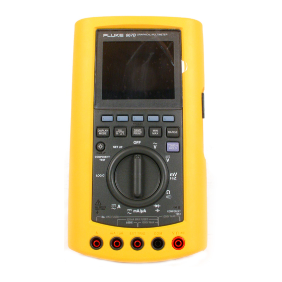
The Graphical» Multimeter combines the industry’s most
advanced multimeter capabilities with the visual power of
trend graphing and waveform display, component testing, and
logic checking together in one easy-to-use, handheld instrument.
The Fluke 867B Graphical Multimeter features:
• Extraordinary 0.025% dc accuracy for critical measurements
• Familiar Fluke multimeter functions like True-rms ac volts
and resistance, joined by capacitance, conductance,
frequency, duty-cycle, pulse-width, period and dB measurements
• Big, bold GMM display, shows multiple numeric readings and
waveforms simultaneously. For example, high- accuracy
True-ims readings combined with waveforms to give a complete
picture of dynamic signals. Waveform display, with dc to 1
MHz bandwidth, provides a clear view of noise, waveform
distortion, and glitches
• Optically isolated, RS-232 Interface for printing and
transferring measurement data, FlukeView* 860 Software
provides a communication link with PCs, for documentation,
analysis and storage. The Fluke SC860 accessory, combines
FlukeView* and cable, making an easy-to-buy interfacing solution
• TrendGraph» works like an electronic chart recorder,
plotting high resolution meter readings for up to 30 hours,
in intervals from 1 second to 15 minutes
• Component test for checking component signatures on
resistors, capacitors, semiconductors and more
показать больше
Руководство по техническому обслуживанию
Hасто́льная кни́га тип:
Руководство по техническому обслуживанию

Страницы:
101
Размер:
3.98 Mbytes (4174330 Bytes)
Язык:
english
Пересмотр:
Hасто́льная кни́га ID:
PN 689312
Дата:
Качество:
Электронный документ, ни сканирование, очень хорошо читается.
Дата загрузки:
2013 11 05
MD5:
348520d13c336c6e4e7e8b3357e29a84
Загрузки:
2115
Информация
This manual includes the following information:
• Specifications (Chapter 1):
• Theory of Operation (Chapter 2):
• General Maintenance (Chapter 3):
• Performance Testing and Calibration procedures (Chapter 4):
• List of Replaceable Parts (Chapter 5):
• Schematic Diagrams and component locators (Chapter 6):
The information in this manual is applicable to both the 867B and 863 models unless
otherwise indicated.
показать больше
Руководство пользователя
Hасто́льная кни́га тип:
Руководство пользователя

Страницы:
112
Размер:
966.23 Kbytes (989417 Bytes)
Язык:
english
Пересмотр:
3
Hасто́льная кни́га ID:
4822 872 00894
Дата:
Качество:
Электронный документ, ни сканирование, очень хорошо читается.
Дата загрузки:
2014 11 30
MD5:
62ea2ba2368868f6f0b157f338fbdfd6
Загрузки:
1256
Информация
1 A Quick Tour
…
1-1
Your Graphical
Multimeter …
1-1
About This
Manual …
1-8
Combo Mode
…
1-9
Meter Mode
…
1-9
View
Mode …
1-9
Trend Mode
…
1-9
Auto Diode Test
Mode …
1-10
Logic Test Mode
…
1-10
Component Test Mode
…
1-10
Sleep
Mode …
1-10
2 Making
Measurements …
2-1
Introduction …
2-1
Measuring AC
Volts …
2-4
Measuring DC Volts
…
2-6
Measuring DC
Millivolts …
2-8
Measuring Ohms, Continuity, and
Conductance … 2-9
Testing Diodes and Measuring Capacitance
… 2-11
Measuring AC and DC Amps
…
2-13
Measuring AC and DC Milliamps and
Microamps … 2-15
Using Component Test
…
2-17
Testing for Logic Activity
…
2-20
Measuring Frequency
…
2-22
3 Some General Descriptions
…
3-1
Introduction
…
3-1
Battery
Considerations …
3-1
Display Blanking (Sleep Mode)
…
3-1
Using the
…
3-2
Backlight (Model(867B)
…
3-2
Adjusting
Contrast …
3-2
General Features
…
3-2
Understanding Display
Features …
3-7
Measurement Connections
…
3-10
4 Using the
Hardkeys …
4-1
Introduction
…
4-1
Using Display Mode Softkeys
…
4-1
Using Frequency Softkeys
…
4-2
Save/Print
Softkeys …
4-3
Min Max Softkeys
…
4-4
Range Softkeys
…
4-5
Touch Hold
…
4-6
5 Using View and Trend Display
Modes …
5-1
Introduction …
5-1
View Display Mode Basics
…
5-1
Using View Mode
Softkeys …
5-2
Setting Up the Time
Base …
5-3
Setting Up the Trigger
…
5-4
Choosing the Acquisition Type
…
5-7
Trend Display Mode
Basics …
5-10
Using Trend Mode Softkeys
…
5-10
6 Using Save, Recall, Print, and Set
Up …
6-1
Introduction …
6-1
Using the Save/Print Softkeys
…
6-1
Saving Screen and
Configuration …
6-3
Recalling Screen or
Configuration …
6-4
Previewing Screen or
Configuration …
6-4
Saving the Present
Configuration …
6-5
Printing …
6-6
Changing the
Configuration …
6-8
7 User
Maintenance …
7-1
Introduction …
7-1
Cleaning
…
7-1
Testing the
Fuses …
7-1
Replacing the Batteries
…
7-2
Replacing the 440 mA Fuses
…
7-2
Replacing the 11A (High Energy)
Fuse …
7-2
Reassembly
…
7-3
Operational
Test …
7-5
Self Test
…
7-5
If Your GMM Does Not Work
…
7-8
8
Specifications …
8-1
General Specifications
…
8-1
показать больше
Технический паспорт
Hасто́льная кни́га тип:
Технический паспорт

Страницы:
1
Размер:
141.62 Kbytes (145020 Bytes)
Язык:
english
Пересмотр:
Hасто́льная кни́га ID:
Дата:
Качество:
Отсканированы документу, все читается.
Дата загрузки:
2016 01 28
MD5:
c1370d72032447c74abc847afea191bd
Загрузки:
618
Добавить комментарий

805 Vibration Meter Быстрый старт
2.26 МБ
805 Vibration Meter Руководство по эксплуатации
2.15 МБ
810 Vibration Tester Users Manual
4.87 МБ
922 Airflow Meter Users Manual
0.44 МБ
971 Temperature Humidity Meter Users Manual
0.17 МБ
975 AirMeterTM Test Tool Users Manual
1.1 МБ
985 Airborne Particle Counter Начало работы
0.64 МБ
985 Airborne Particle Counter Руководство пользователя
0.87 МБ
CO-220 Carbon Monoxide Meter Instruction Sheet
0.12 МБ
VT02 Руководство пользователя
1.04 МБ
Краткое руководство: начало работы с Fluke 8808A
0.8 МБ
Руководство по калибровке Fluke 1750
1.14 МБ
Руководство пользователя Fluke 1507/1503
0.79 МБ
Руководство пользователя Fluke 1523 и 1524
3.87 МБ
Руководство пользователя Fluke 1550B
1.09 МБ
Руководство пользователя Fluke 1551A
0.57 МБ
Руководство пользователя Fluke 1555/1550C
1.22 МБ
Руководство пользователя Fluke 1587/1577
2.49 МБ
Руководство пользователя Fluke 1621
0.37 МБ
Руководство пользователя Fluke 1623
2.43 МБ
Руководство пользователя Fluke 1625
2.19 МБ
Руководство пользователя Fluke 1630
0.39 МБ
Руководство пользователя Fluke 1650B
3.71 МБ
Руководство пользователя Fluke 1710
0.49 МБ
Руководство пользователя Fluke 1735
1.4 МБ
Руководство пользователя Fluke 1744/1743
4.65 МБ
Руководство пользователя Fluke 1745
2.69 МБ
Руководство пользователя Fluke 1760
3.13 МБ
Руководство пользователя Fluke 2042
1.08 МБ
Руководство пользователя Fluke 321/322
1.07 МБ
Руководство пользователя Fluke 333
1.06 МБ
Руководство пользователя Fluke 336
0.46 МБ
Руководство пользователя Fluke 345
1.77 МБ
Руководство пользователя Fluke 353/355
0.94 МБ
Руководство пользователя Fluke 360
0.19 МБ
Руководство пользователя Fluke 373
1.22 МБ
Руководство пользователя Fluke 374/375/376
1.7 МБ
Руководство пользователя Fluke 381
1.15 МБ
Руководство пользователя Fluke 411
0.21 МБ
Руководство пользователя Fluke 416
0.76 МБ
Руководство пользователя Fluke 4180
1.38 МБ
Руководство пользователя Fluke 421
2.15 МБ
Руководство пользователя Fluke 434/435
2.23 МБ
Руководство пользователя Fluke 43B
1.6 МБ
Руководство пользователя Fluke 51/ 52 Series II
0.16 МБ
Руководство пользователя Fluke 53/54 Series II
0.22 МБ
Руководство пользователя Fluke 561
0.9 МБ
Руководство пользователя Fluke 566/568
1.22 МБ
Руководство пользователя Fluke 572
1.69 МБ
Руководство пользователя Fluke 574
3.83 МБ
Руководство пользователя Fluke 576
3.24 МБ
Руководство пользователя Fluke 59 MAX/59 MAX +
1.46 МБ
Руководство пользователя Fluke 61
5.96 МБ
Руководство пользователя Fluke 63, 66, 68
0.77 МБ
Руководство пользователя Fluke 65
0.13 МБ
Руководство пользователя Fluke 705
0.27 МБ
Руководство пользователя Fluke 707
0.48 МБ
Руководство пользователя Fluke 707ex
1.28 МБ
Руководство пользователя Fluke 712
0.32 МБ
Руководство пользователя Fluke 714
0.28 МБ
Руководство пользователя Fluke 715
0.39 МБ
Руководство пользователя Fluke 717
0.5 МБ
Руководство пользователя Fluke 718
1.72 МБ
Руководство пользователя Fluke 718ex
1.16 МБ
Руководство пользователя Fluke 719
1.28 МБ
Руководство пользователя Fluke 724
0.98 МБ
Руководство пользователя Fluke 725
1.31 МБ
Руководство пользователя Fluke 725Ex
2.74 МБ
Руководство пользователя Fluke 726
1.44 МБ
Руководство пользователя Fluke 741B/743B
4.26 МБ
Руководство пользователя Fluke 744
1.96 МБ
Руководство пользователя Fluke 771
0.63 МБ
Руководство пользователя Fluke 772/773
1.46 МБ
Руководство пользователя Fluke 787
0.55 МБ
Руководство пользователя Fluke 789
0.87 МБ
Руководство пользователя Fluke 810
4.87 МБ
Руководство пользователя Fluke 8808A
2.38 МБ
Руководство пользователя Fluke 8845A/8846A
2.39 МБ
Руководство пользователя Fluke 902
0.7 МБ
Руководство пользователя Fluke 9040
0.22 МБ
Руководство пользователя Fluke 9062
0.23 МБ
Руководство пользователя Fluke 9140
3.86 МБ
Руководство пользователя Fluke 922
0.44 МБ
Руководство пользователя Fluke 971
0.17 МБ
Руководство пользователя Fluke 975
0.68 МБ
Руководство пользователя Fluke 983
0.56 МБ
Руководство пользователя Fluke CO-210
0.06 МБ
Руководство пользователя Fluke CO-220
0.12 МБ
Руководство пользователя Fluke FoodPro Plus
0.71 МБ
Руководство пользователя Fluke Norma 4000/5000
1.44 МБ
Руководство пользователя Fluke Power Log
1.18 МБ
Руководство пользователя Fluke T100
0.14 МБ
Руководство пользователя Fluke T5
1.07 МБ
Руководство пользователя Fluke T50
0.16 МБ
����������� �������� FLUKE-867B —> ������������ —> �������� � �������
| ����������� ������������ | |||
|---|---|---|---|
| max | ���������� | ����������� | |
| ���������� ���������� | 1�� | 0.1�� | ±(0.03% + 2) |
| ���������� ���������� | 1�� | 0.1�� | ±(0.1% + 2) |
| ���������� ��� | 10A | 0.1��� | ±(0.75% + 10) |
| ���������� ��� | 10A | 0.1��� | ±(0.75% + 10) |
| ������������� | 30��� | 0.1�� | ±(0.7% + 2) |
| ��������� �������: | �� | ||
| ��������� �������: | �� | ||
| ��������� �����������: | ��� | ||
| ����������� ������ ������: | |||
| ��������� ���������� p-n ���������: | �� | ||
| ��������� ���������: | ��� | ||
| ������������� ���������: | �� | ||
| ������� �����: | ��� | ||
| ��������� ������������������� �������� �������: | ��� ������ | ||
| ����������� ������� ��������: | ��� | ||
| ������ � ������: | ��� | ||
| ����� ��������������: | |||
| ����� � �����������: | ��������� ������������� ��������� RS-232 | ||
| �������� �����: | 5 �����, ������������ ������������ �����: 50000 | ||
| �������� �����: | ��� | ||
| �������� �������: | ������� 9 � | ||
| ���������� �������: | 246 x 137 x 69 ��. | ||
| ���: | 1 �. | ||
| �������������������: | EN61010-1 CAT III 1000V | ||
| �������� ��������: | C81Y �������� ����� ������� ����� � ����������, ������� TL75, ������ ���� «��������» AC72(2), ������� 9�, ����������� ������������. | ||
| �������������� ����������: | PV350 ������ ��� ��������� �������� TL28A ������ ���� «��������» 63″ BC7217 �������� ���������� PAC91 ������� ��� ����������� � �������� SC860 ����������� ����������� � ��������� ������������� ������ 80i-400 ������� ����� ��� ����������� ���� i410 AC/DC ������� ����� ��� ����������� � ����������� ���� i200 ������� ����� (������ ��� ����������� ����) i1010 ������� ����� ��� ����������� � ����������� ���� 80T-IR �������� (������������� ������������� �������) 80PK-2A ������������� ������� ��� ��������� � ����� (K-Type) 80PK-3A ������������� ������� ����������� ���� ��� ������� ������������ (K-Type) 80PK-4A ������������� ������� ��� ������� � �����, ����� ��������� � ��������� (K-Type) 80PK-5A ������������� ������� ��� ������� ��������������, ��������� � �����, ����� ��������� � ��������� (K-Type) 80PK-6A ������������� ������� ��� �� ������������ ���� (������� � �����, ����� ��������� � ���������) (K-Type) 80PK-7 ������������� ������� ����������� ���� ��� ������������ � ���������� ������������� (K-Type) 80PK-8 ������������� ������� ��� ���� ��������� �� 6.4 �� 34.9 �� 80T-150U ������������� ������������� ������� 80TK ������ ��������� AC220 SureGripTM ������ ���� «��������» AC280 SureGripTM ����� ������� TL 40 ����� ��������� TL74 �������� 4 �� TL930 �������������� ���� 61 �� TL930 �������������� ���� 61 �� TL932 �������������� ���� 91 �� TL935 ����� �������������� ������ TL940 ����� ��������� � ������� (����) TL950 ����� ��������� � ������� (����) TL960 ����� ��������� � ������� (�����) TL970 ����� ������� � ������ TP912 ������� ������� ��� ��������� TL910 TP920 ����� ��������� ��� ��������� |
- Дисплей позволяет просматривать форму сигнала (в виде осциллограммы) и измеренное значение на одном экране
- Максимальное индицируемое число 50000
- Улучшенная версия с повышенной яркостью подсветки экрана ( 867BE )
- Большой дисплей позволяет считывать цифровые и графические данные одновременно
- Функция TrendGrahp действует как электронный самописец и выдает показания измерителя в течение 30 часов с интервалом от 1 с до 15 мин
- Функции измерения напряжения переменного тока в децибеллах: dBm и dBV
- Возможность измерять эффективные (True RMS) значения переменного тока
- Функция регистрации минимального, максимального и среднего значений (Min/Max/Average recording) с соответствующей временной отметкой, пик минимума и максимума за интервал от 250 мкс
- Сертифицирован в соответствии с IEC 1010-1, UL 3111, TŰV EN 61010-1, CSA CAN/CSA C 22.2 No.1010-1
- Проверка активности логических цепей
- Оптически изолированный интерфейс RS-232
- Габариты 246 × 137 × 70 мм
- Вес 1.4 кг
- Адаптер питания аккумуляторов/сетевого питания
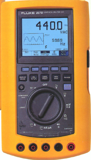
Подробное описание
Технические характеристики Fluke 867B
|
Функция |
Диапазон |
Наилучшее |
Точность |
|
Постоянное напряжение |
0.3 / 3 / 30 / 300 / 1000 В |
0.1 мВ |
±(0.025%+2) |
|
Переменное напряжение |
0.3 / 3 / 30 / 300 / 1000 В |
0.1 мВ |
±(0.4%+40) |
|
Постоянный ток |
0.3 / 3 / 30 / 300 мА / 3 / 10 А |
0.1 мкА |
±(0.1%+2) |
|
Переменный ток |
0.3 / 3 / 30 / 300 мА / 3 / 10 А |
0.1 мкА |
±(0.75%+10) |
|
Диапазон частот 300 кГц |
|||
|
Сопротивление |
0.3 / 3 / 30 / 300 кOм / 3 / 30 МОм |
0.1Ом |
±(0.7%+2) |
|
Емкость |
0.01 / 0.1 / 1 / 10 / 100 / 1000 / 10000 мкФ |
0.001 пФ |
+(1.9%+2) |
|
Частота |
1 / 10 / 100 кГц / 1 / 2 / 10 МГц |
0.1 Гц |
±(0.05%+1) |
|
Измерения в dBm и dB |
Относительно сопротивлений 2…1200 Ом |
±0.5 dB |
|
|
Измерение параметров p-n переходов |
Да |
Варианты написания:
867B 867BE, 867B 867BE
Fluke 867B Цифровой универсальный измерительный прибор
Производитель:
Модель:
867B
Дата:
1997
Категория:
Группа:
Описание:
Информация
The Graphical» Multimeter combines the industry’s most
advanced multimeter capabilities with the visual power of
trend graphing and waveform display, component testing, and
logic checking together in one easy-to-use, handheld instrument.
The Fluke 867B Graphical Multimeter features:
• Extraordinary 0.025% dc accuracy for critical measurements
• Familiar Fluke multimeter functions like True-rms ac volts
and resistance, joined by capacitance, conductance,
frequency, duty-cycle, pulse-width, period and dB measurements
• Big, bold GMM display, shows multiple numeric readings and
waveforms simultaneously. For example, high- accuracy
True-ims readings combined with waveforms to give a complete
picture of dynamic signals. Waveform display, with dc to 1
MHz bandwidth, provides a clear view of noise, waveform
distortion, and glitches
• Optically isolated, RS-232 Interface for printing and
transferring measurement data, FlukeView* 860 Software
provides a communication link with PCs, for documentation,
analysis and storage. The Fluke SC860 accessory, combines
FlukeView* and cable, making an easy-to-buy interfacing solution
• TrendGraph» works like an electronic chart recorder,
plotting high resolution meter readings for up to 30 hours,
in intervals from 1 second to 15 minutes
• Component test for checking component signatures on
resistors, capacitors, semiconductors and more
показать больше
Руководство по техническому обслуживанию
Hасто́льная кни́га тип:
Руководство по техническому обслуживанию
Страницы:
101
Размер:
3.98 Mbytes (4174330 Bytes)
Язык:
english
Пересмотр:
Hасто́льная кни́га ID:
PN 689312
Дата:
Качество:
Электронный документ, ни сканирование, очень хорошо читается.
Дата загрузки:
2013 11 05
MD5:
348520d13c336c6e4e7e8b3357e29a84
Загрузки:
2304
Информация
This manual includes the following information:
• Specifications (Chapter 1):
• Theory of Operation (Chapter 2):
• General Maintenance (Chapter 3):
• Performance Testing and Calibration procedures (Chapter 4):
• List of Replaceable Parts (Chapter 5):
• Schematic Diagrams and component locators (Chapter 6):
The information in this manual is applicable to both the 867B and 863 models unless
otherwise indicated.
показать больше
Руководство пользователя
Hасто́льная кни́га тип:
Руководство пользователя
Страницы:
112
Размер:
966.23 Kbytes (989417 Bytes)
Язык:
english
Пересмотр:
3
Hасто́льная кни́га ID:
4822 872 00894
Дата:
Качество:
Электронный документ, ни сканирование, очень хорошо читается.
Дата загрузки:
2014 11 30
MD5:
62ea2ba2368868f6f0b157f338fbdfd6
Загрузки:
1359
Информация
1 A Quick Tour
…
1-1
Your Graphical
Multimeter …
1-1
About This
Manual …
1-8
Combo Mode
…
1-9
Meter Mode
…
1-9
View
Mode …
1-9
Trend Mode
…
1-9
Auto Diode Test
Mode …
1-10
Logic Test Mode
…
1-10
Component Test Mode
…
1-10
Sleep
Mode …
1-10
2 Making
Measurements …
2-1
Introduction …
2-1
Measuring AC
Volts …
2-4
Measuring DC Volts
…
2-6
Measuring DC
Millivolts …
2-8
Measuring Ohms, Continuity, and
Conductance … 2-9
Testing Diodes and Measuring Capacitance
… 2-11
Measuring AC and DC Amps
…
2-13
Measuring AC and DC Milliamps and
Microamps … 2-15
Using Component Test
…
2-17
Testing for Logic Activity
…
2-20
Measuring Frequency
…
2-22
3 Some General Descriptions
…
3-1
Introduction
…
3-1
Battery
Considerations …
3-1
Display Blanking (Sleep Mode)
…
3-1
Using the
…
3-2
Backlight (Model(867B)
…
3-2
Adjusting
Contrast …
3-2
General Features
…
3-2
Understanding Display
Features …
3-7
Measurement Connections
…
3-10
4 Using the
Hardkeys …
4-1
Introduction
…
4-1
Using Display Mode Softkeys
…
4-1
Using Frequency Softkeys
…
4-2
Save/Print
Softkeys …
4-3
Min Max Softkeys
…
4-4
Range Softkeys
…
4-5
Touch Hold
…
4-6
5 Using View and Trend Display
Modes …
5-1
Introduction …
5-1
View Display Mode Basics
…
5-1
Using View Mode
Softkeys …
5-2
Setting Up the Time
Base …
5-3
Setting Up the Trigger
…
5-4
Choosing the Acquisition Type
…
5-7
Trend Display Mode
Basics …
5-10
Using Trend Mode Softkeys
…
5-10
6 Using Save, Recall, Print, and Set
Up …
6-1
Introduction …
6-1
Using the Save/Print Softkeys
…
6-1
Saving Screen and
Configuration …
6-3
Recalling Screen or
Configuration …
6-4
Previewing Screen or
Configuration …
6-4
Saving the Present
Configuration …
6-5
Printing …
6-6
Changing the
Configuration …
6-8
7 User
Maintenance …
7-1
Introduction …
7-1
Cleaning
…
7-1
Testing the
Fuses …
7-1
Replacing the Batteries
…
7-2
Replacing the 440 mA Fuses
…
7-2
Replacing the 11A (High Energy)
Fuse …
7-2
Reassembly
…
7-3
Operational
Test …
7-5
Self Test
…
7-5
If Your GMM Does Not Work
…
7-8
8
Specifications …
8-1
General Specifications
…
8-1
показать больше
Технический паспорт
Hасто́льная кни́га тип:
Технический паспорт
Страницы:
1
Размер:
141.62 Kbytes (145020 Bytes)
Язык:
english
Пересмотр:
Hасто́льная кни́га ID:
Дата:
Качество:
Отсканированы документу, все читается.
Дата загрузки:
2016 01 28
MD5:
c1370d72032447c74abc847afea191bd
Загрузки:
697
Добавить комментарий
Руководства Fluke 867B Размер файлов: 8733 KB, Язык: English, Формат: pdf, Платформа: Windows/Linux, Дата: 2015-09-17
На данной странице вы можете скачать руководства Fluke 867B. Мы предлагаем вам ознакомиться с руководством пользователя, инструкцией по сервисному обслуживанию и ремонту.
Также здесь вы найдете список заказных номеров на комплектующие Fluke 867B.
Все файлы предоставляются исключительно в ознакомительных целях. И не являютя руководством по ремонту, а направлены лишь на то чтобы помочь вам более детально ознакомиться с принципом построения устройства.
Содержимое представленных здесь руководств требуют от вас знания технического английского языка.
Если вы собираетесь скачать руководство по сервисному обслуживанию Fluke 867B, иными словами сервис мануал, вы дожны обладать хотя бы минимальными познаниями в области электроники и пониманием базовых принципов работы электромеханических устройств.
Для просмотра руководств вам понадобится Adobe Acrobat Reader версии 9 и выше либо другая программа для просмотра pdf файлов.
В связи с популярностью информации представленной на сайте и ее бесплатного предоставления конечному пользователю, убедительная просьба использовать специальные программные продукты для многопотокового скачивания файлов.
Руководства для Fluke 867B
- Руководство пользователя (User manual)
- Руководство по сервисному обслуживанию (Service manual)
- Руководство по ремонту (Repair manual)
- Перечень комплектующих (PartList)
����������� �������� FLUKE-867B —> ������������ —> �������� � �������
| ����������� ������������ | |||
|---|---|---|---|
| max | ���������� | ����������� | |
| ���������� ���������� | 1�� | 0.1�� | ±(0.03% + 2) |
| ���������� ���������� | 1�� | 0.1�� | ±(0.1% + 2) |
| ���������� ��� | 10A | 0.1��� | ±(0.75% + 10) |
| ���������� ��� | 10A | 0.1��� | ±(0.75% + 10) |
| ������������� | 30��� | 0.1�� | ±(0.7% + 2) |
| ��������� �������: | �� | ||
| ��������� �������: | �� | ||
| ��������� �����������: | ��� | ||
| ����������� ������ ������: | |||
| ��������� ���������� p-n ���������: | �� | ||
| ��������� ���������: | ��� | ||
| ������������� ���������: | �� | ||
| ������� �����: | ��� | ||
| ��������� ������������������� �������� �������: | ��� ������ | ||
| ����������� ������� ��������: | ��� | ||
| ������ � ������: | ��� | ||
| ����� ��������������: | |||
| ����� � �����������: | ��������� ������������� ��������� RS-232 | ||
| �������� �����: | 5 �����, ������������ ������������ �����: 50000 | ||
| �������� �����: | ��� | ||
| �������� �������: | ������� 9 � | ||
| ���������� �������: | 246 x 137 x 69 ��. | ||
| ���: | 1 �. | ||
| �������������������: | EN61010-1 CAT III 1000V | ||
| �������� ��������: | C81Y �������� ����� ������� ����� � ����������, ������� TL75, ������ ���� «��������» AC72(2), ������� 9�, ����������� ������������. | ||
| �������������� ����������: | PV350 ������ ��� ��������� �������� TL28A ������ ���� «��������» 63″ BC7217 �������� ���������� PAC91 ������� ��� ����������� � �������� SC860 ����������� ����������� � ��������� ������������� ������ 80i-400 ������� ����� ��� ����������� ���� i410 AC/DC ������� ����� ��� ����������� � ����������� ���� i200 ������� ����� (������ ��� ����������� ����) i1010 ������� ����� ��� ����������� � ����������� ���� 80T-IR �������� (������������� ������������� �������) 80PK-2A ������������� ������� ��� ��������� � ����� (K-Type) 80PK-3A ������������� ������� ����������� ���� ��� ������� ������������ (K-Type) 80PK-4A ������������� ������� ��� ������� � �����, ����� ��������� � ��������� (K-Type) 80PK-5A ������������� ������� ��� ������� ��������������, ��������� � �����, ����� ��������� � ��������� (K-Type) 80PK-6A ������������� ������� ��� �� ������������ ���� (������� � �����, ����� ��������� � ���������) (K-Type) 80PK-7 ������������� ������� ����������� ���� ��� ������������ � ���������� ������������� (K-Type) 80PK-8 ������������� ������� ��� ���� ��������� �� 6.4 �� 34.9 �� 80T-150U ������������� ������������� ������� 80TK ������ ��������� AC220 SureGripTM ������ ���� «��������» AC280 SureGripTM ����� ������� TL 40 ����� ��������� TL74 �������� 4 �� TL930 �������������� ���� 61 �� TL930 �������������� ���� 61 �� TL932 �������������� ���� 91 �� TL935 ����� �������������� ������ TL940 ����� ��������� � ������� (����) TL950 ����� ��������� � ������� (����) TL960 ����� ��������� � ������� (�����) TL970 ����� ������� � ������ TP912 ������� ������� ��� ��������� TL910 TP920 ����� ��������� ��� ��������� |