-
Contents
-
Table of Contents
-
Troubleshooting
-
Bookmarks
Quick Links
®
Fluke 125
Industrial ScopeMeter
Users Manual
GB
Dec 2006, Rev. 3, 09/2009
© 2006, 2007, 2008, 2009 Fluke Corporation. All rights reserved.
All product names are trademarks of their respective companies.
Related Manuals for Fluke 125
Summary of Contents for Fluke 125
-
Page 1
® Fluke 125 Industrial ScopeMeter Users Manual Dec 2006, Rev. 3, 09/2009 © 2006, 2007, 2008, 2009 Fluke Corporation. All rights reserved. All product names are trademarks of their respective companies. -
Page 3
Fluke’s warranty obligation is limited, at Fluke’s option, to refund of the purchase price, free of charge repair, or replacement of a defective product which is returned to a Fluke authorized service center within the warranty period. -
Page 4: Service Centers
SERVICE CENTERS To locate an authorized service center, visit us on the World Wide Web: http://www.fluke.com or call Fluke using any of the phone numbers listed below: +1-888-993-5853 in U.S.A. and Canada +31-402-675-200 in Europe +1-425-446-5500 from other countries…
-
Page 5: Table Of Contents
Table of Contents Chapter Title Page Declaration of Conformity………………..0-1 Unpacking the Test Tool Kit………………. 0-2 Safely Using the Test Tool………………… 0-4 General Operating Instructions ………………..1-1 Introduction ……………………1-1 Preparations for Use …………………. 1-1 Powering the Test Tool ………………..1-1 Resetting the Test Tool………………..
-
Page 6
Fluke 125 Users Manual Input B ……………………1-5 COM ……………………. 1-5 Measurement Probes & Settings ………………. 1-6 Scope/Meter Mode……………………2-1 Introduction ……………………2-1 Selecting the Scope/Meter Mode………………. 2-1 Reading the Screen ………………….. 2-2 Displaying an Unknown Signal with Connect-and-View™ (Auto Set) ……2-3 Making Measurements ……………….. -
Page 7
Contents (continued) Reversing the Polarity of the Displayed Waveform…………2-16 Triggering on a Waveform ………………… 2-17 Setting Trigger Level and Slope …………….2-17 Selecting the Trigger Parameters…………….2-18 Isolated Triggering ………………..2-19 Triggering on Video Signals ………………2-20 Triggering on a Specific Video Line…………….2-21 Making Cursor Measurements ……………… -
Page 8
Fluke 125 Users Manual Plotting Measurements over Time (TrendPlot )…………..5-1 Introduction ……………………5-1 Starting/Stopping a TrendPlot ………………5-1 Changing the TrendPlot Reading………………. 5-3 Making TrendPlot Cursor Measurements …………..5-3 Saving and Recalling Data Sets ………………… 6-1 Introduction ……………………6-1 Saving Data Sets …………………. -
Page 9
Setting the Power Down Timer……………… 9-4 Changing the Auto Set Options………………9-5 Using Proper Grounding ………………..9-6 Solving Printing and Other Communication Errors…………9-7 Battery Testing of Fluke Accessories…………….9-7 Specifications …………………….. 10-1 Introduction ……………………10-1 Dual Input Oscilloscope ………………..10-2 Dual Input Meter …………………. -
Page 10
Fluke 125 Users Manual Appendices…………………. 0-1 Bushealth Measurements ………………….. A-1 Introduction ……………………A-1 General…………………….. A-1 Use of Probes and Accessories………………A-2 Tips and Hints per Bustype……………….. A-3 AS-i Bus ……………………A-3 CAN Bus/DeviceNet………………..A-4 Interbus S ……………………. A-5 ControlNet……………………. A-5 Modbus IEA-232/RS-232. -
Page 11: Declaration Of Conformity
Safety Requirements for Electrical Equipment for ® ScopeMeter test tool Measurement, Control, and Laboratory Use Manufacturer EN61326-1: 2006 Fluke Industrial B.V. Electrical equipment for Lelyweg 14 measurements and laboratory 7602 EA Almelo use -EMC requirements- The Netherlands The tests have been performed in a…
-
Page 12: Unpacking The Test Tool Kit
When new, the rechargeable battery pack is not The following items are included in your test tool kit. (see fully charged. See Chapter 2. Figure 1.): Description Fluke 125 Fluke 125/S Fluke Test Tool Model 125 Model 125 • • Rechargeable NiMH Battery Pack •…
-
Page 13
Unpacking the Test Tool Kit S-Version (2x) (3x) Figure 1. ScopeMeter Test Tool Kit… -
Page 14: Safely Using The Test Tool
Do no dispose of this product as unsorted municipal A Warning identifies conditions and actions that pose waste. Go to Fluke’s website for recycling information. hazard(s) to the user. Warning Symbols used on the test tool and in this manual are explained in the next table.
-
Page 15
• Before use check that the selected/indicated and adapters supplied with the Test Tool, or voltage range on the PM8907 matches the indicated as suitable for the Fluke 125 Test local line power voltage and frequency. Tool. • For the PM8907/808 universal Battery •… -
Page 16
Fluke 125 Users Manual If Safety Features are Impaired Max. Input Voltages Input A and B directly……..600 V CAT III Use of the Test Tool in a manner not specified may impair the protection provided by the equipment. Input A and B via BB120……300 V CAT III Input A and B via STL120 ……600 V CAT III… -
Page 17: General Operating Instructions
Chapter 1 General Operating Instructions Introduction This Chapter provides a step-by-step introduction to the general test tool functions. Preparations for Use At delivery, the batteries may be empty and must be charged for at last 7 hours. Deeply discharged batteries may even cause the test tool not to start up when it is Figure 1-1.
-
Page 18: Resetting The Test Tool
Fluke 125 Users Manual Resetting the Test Tool If you want to restore the test tool settings as delivered from the factory, do the following: Turn the test tool off. Press and hold. Press and release. The test tool turns on, and you should hear a double beep, indicating the Reset was successful.
-
Page 19: Changing Backlight
General Operating Instructions Changing Backlight Changing Backlight Changing Contrast After power-up, the screen has a high bright display. To change the screen contrast, do the following: To save battery power, the screen has an economic Invoke the LIGHT-CONTRAST brightness display when operated on the battery pack (no button bar.
-
Page 20: Making Selections In A Menu
Fluke 125 Users Manual Notes Making Selections in a Menu − Pressing a second time closes this How to use the menus is illustrated in the example below on how to adjust the test tool for use with a certain printer menu and resumes normal measurement.
-
Page 21: Looking At The Measurement Connections
General Operating Instructions Looking at the Measurement Connections Warning Looking at the Measurement Connections To avoid electrical shock or fire, use only one (common) connection, or ensure that Look at the top of the test tool. The test tool provides two all connections to COM are at the same 4-mm safety shielded banana jack inputs (red input A and…
-
Page 22: Measurement Probes & Settings
Fluke 125 Users Manual Measurement Probes & Settings For the SCOPE/METER mode and the HARMONICS mode various probes can be used for the test tool measurement functions, for example a 10:1 voltage probe, a 1mV/°C Temperature probe, or a 10 mV/A current clamp.
-
Page 23: Scope/Meter Mode
Chapter 2 Scope/Meter Mode Introduction Selecting the Scope/Meter Mode The Scope/Meter mode offers you To select the Scope/Meter mode do the following: • a dual-input 40 MHz digital oscilloscope Open the application mode menu. • two 5,000 counts true-RMS digital multimeters This Chapter provides a step-by-step introduction to the Scope and Meter measurements.
-
Page 24: Reading The Screen
Fluke 125 Users Manual Reading the Screen The screen is divided into three areas: Reading area, Waveform area, and Menu area. Refer to Figure 2-1 during the following. Displays the numeric readings. If Reading area only input A is on, you will see the input A readings only.
-
Page 25: Displaying An Unknown Signal With Connect-And-View™ (Auto Set)
Scope/Meter Mode Displaying an Unknown Signal with Connect-and-View™ (Auto Set) Displaying an Unknown Signal with Connect-and-View™ (Auto Set) The Connect-and-View™ function enables hands-off operation to display complex unknown signals. This function optimizes the position, range, time base, and triggering and assures a stable display on nearly all waveforms.
-
Page 26: Making Measurements
Fluke 125 Users Manual Making Measurements Temperature measurements See figure 2-6. Use a 1 mV/°C temperature transmitter The reading area displays the numeric readings of the (not available in all countries) to get the correct chosen measurements on the waveform that is applied to temperature reading.
-
Page 27
Scope/Meter Mode Making Measurements Figure 2-4. Ohms, Continuity, Diode, Capacitance Measurement Setup Figure 2-6. Temperature Measurement Setup BB120 BB120 10 mV/A — 1 mV/A 10 mV/A — 1 mV/A Figure 2-5. Current Measurement Setup Figure 2-7. Power Measurement Setup… -
Page 28: Selecting A Measurement Function
Fluke 125 Users Manual Selecting a measurement function. Highlight Hz. To choose a frequency measurement for Input A, do the following: Open the A MEASUREMENTS Accept the Hz measurement. menu. Observe that Hz is now the main reading. The former main reading has now moved to the smaller secondary reading position.
-
Page 29
Scope/Meter Mode Making Measurements Highlight PEAK… Open the PEAK submenu. Highlight PEAK-PEAK. Accept the pk-pk measurement. Figure 2-8. Hz and Vpp as Main Readings Now, you will see a screen like Figure 2-8. -
Page 30: Freezing The Screen
Fluke 125 Users Manual Freezing the Screen Holding a Stable Reading ® You can freeze the screen (all readings and waveforms) at The Touch Hold mode captures a stable main (large) any time. reading on the display. When a new stable reading is detected, the test tool beeps and displays the new Freeze the screen.
-
Page 31: Making Relative Measurements
Scope/Meter Mode Making Relative Measurements Making Relative Measurements Zero Reference displays the present measurement result with respect to the defined value. This feature is useful when you need to monitor the measured value in relation to a known good value. Open the A MEASUREMENTS menu.
-
Page 32: Selecting Auto/Manual Ranges
Fluke 125 Users Manual Selecting Auto/Manual Ranges Changing the Graphic Representation on the Screen Press to automatically adjust the position, range, time base, and triggering (Connect-and-View). This From Auto range, you can use the light-gray rocker keys to assures a stable display on nearly all waveforms. The…
-
Page 33: Positioning The Waveform On The Screen
Scope/Meter Mode Changing the Graphic Representation on the Screen Positioning the Waveform on the Screen Considerable flexibility is offered in moving the waveform(s) around the screen. Press until you have left any open menu. Observe that the following main menu appears on bottom of the screen.
-
Page 34: Smoothing Waveforms And Readings
Fluke 125 Users Manual WAVEFORM SMOOTH suppresses noise without loss of Smoothing Waveforms and Readings bandwidth. Waveform samples with and without smoothing To smooth the waveform, do the following: are shown in Figure 2-11. Open the application menu. READING SMOOTH: long averaging, stable reading READING FAST: short averaging, fast response Open the SMOOTH..
-
Page 35: Displaying The Envelope Of A Waveform
Scope/Meter Mode Changing the Graphic Representation on the Screen Displaying the Envelope of a Waveform The test tool records the envelope (minimum and maximum) of the live waveforms A and B. Repeat the first two actions of ‘Smoothing the Waveform’, and then do the following: Highlight ENVELOPE.
-
Page 36: Acquiring The Waveform
Fluke 125 Users Manual The test tool will now have a screen like Figure 2-13. Acquiring the Waveform Wait: appears on bottom of the screen to indicate that the Making a Single Acquisition test tool is waiting for a trigger.
-
Page 37: Recording Slow Signals Over A Long Period Of Time
Scope/Meter Mode Acquiring the Waveform Recording Slow Signals over a Long Period of Time The roll mode function supplies a visual log of waveform activity and is especially useful when you measure lower frequency waveforms. Open the application menu.. Open the TRIGGER… submenu. Highlight A.
-
Page 38: Selecting Ac-Coupling
Fluke 125 Users Manual Selecting AC-Coupling Reversing the Polarity of the Displayed Waveform Use AC-coupling when you wish to observe a small AC To invert the input A waveform, do the following: signal that rides on a DC signal. Open the A MEASUREMENTS To select AC-coupling on input A, do the following: menu.
-
Page 39: Triggering On A Waveform
Scope/Meter Mode Triggering on a Waveform Setting Trigger Level and Slope Triggering on a Waveform For quick operation, use the AUTO SET key to Triggering tells the test tool when to begin displaying the automatically trigger on nearly all signals. waveform.
-
Page 40: Selecting The Trigger Parameters
Fluke 125 Users Manual Selecting the Trigger Parameters To trigger on the input A waveform, with automatic screen update, and to configure the auto range triggering for waveforms down to 1 Hz, do the following: Open the applications menu. Open the TRIGGER submenu Figure 2-15.
-
Page 41: Isolated Triggering
Scope/Meter Mode Triggering on a Waveform Isolated Triggering Accept all trigger selections and return to normal measurement. Use the optically isolated trigger probe (ITP120, optional) to trigger on an external source, and to isolate the test tool Note from a trigger waveform. See Figure 2-16. Setting the automatic triggering to >1Hz will slow To choose the isolated trigger probe, select ‘EXT’…
-
Page 42: Triggering On Video Signals
Fluke 125 Users Manual Triggering on Video Signals Highlight POSITIVE. • Apply an interlaced video signal to the red input A. Accept the video trigger To trigger on a random video line, continue from point selections . of the previous example as follows: Trigger level and slope are now fixed.
-
Page 43: Triggering On A Specific Video Line
Scope/Meter Mode Triggering on a Waveform To choose line 135, do the following: Triggering on a Specific Video Line To view a specific video line in more detail you can select Enable video line selection. the line number. To measure on a selected video line, continue from point of the previous example as follows: Select number 135.
-
Page 44: Making Cursor Measurements
Fluke 125 Users Manual Note Making Cursor Measurements Even when the key labels are not displayed at the Cursors allow you to make precise digital measurements bottom of the screen, you can still use the arrow on waveforms. For 3 phase power measurements cursors keys.
-
Page 45: Using Vertical Cursors On A Waveform
Scope/Meter Mode Making Cursor Measurements Using Vertical Cursors on a Waveform To use the cursors for a time measurement, do the following: From Scope mode, display the Cursor Key functions. Press to highlight . Observe that two vertical cursors are displayed.
-
Page 46
Fluke 125 Users Manual Making Rise Time Measurements To measure rise time, do the following: From Scope mode, display the Cursor Key functions. Press to highlight (rise time). Observe that two horizontal cursors are displayed. If only one trace is displayed, select MANUAL or AUTO. -
Page 47: Using The 10:1 Probe For High Frequency Measurements
Scope/Meter Mode Using the 10:1 Probe for High Frequency Measurements. Using the 10:1 Probe for High Frequency Open the PROBE on A menu Measurements. Highlight 10:1 V The test tool is supplied with a model VP40 10:1 Probe. Use of this Probe is recommended when you measure high frequency signals in circuits with a high impedance.
-
Page 48
Fluke 125 Users Manual 2-26… -
Page 49: Harmonics
Chapter 3 Harmonics Introduction Measuring Harmonics In the Harmonics function the test tool measures You can display harmonics of: harmonics to the 33 (for 400 Hz up to 25 ). Related data • Voltage measurements on Input A such as DC components., THD (Total Harmonic •…
-
Page 50: Performing Harmonics Measurements
Fluke 125 Users Manual Performing Harmonics Measurements Open the application mode menu. To perform harmonics measurements do the following: Connect the inputs as indicated in figure 3-1 Connect input A for VOLT and for WATT, connect input B for AMP and for WATT.
-
Page 51
Harmonics Measuring Harmonics Select %f to display harmonics bars as a percentage of the fundamental signal. Select %r to display harmonics bars as a percentage of the total rms signal Show the waveform screen. Show the bars screen. For the waveform screen use the F1 key to display the voltage (input A), the current (input B), or both waveforms. -
Page 52: Zooming Harmonics
Fluke 125 Users Manual Zooming Harmonics Using Cursors If the harmonics bars screen is displayed you can zoom Cursors allow you to make precise digital measurements vertically for a more detailed view. on harmonics bars. Press to vertically zoom in or out.
-
Page 53: Reading The Harmonics Screen
Harmonics Measuring Harmonics Reading the Harmonics Screen Depending on the test tool settings the readings show different measurement units. Table 3-1 shows the readings for VOLT/AMP/WATT and CURSOR OFF . Table 3-2 shows the readings for VOLT/AMP/WATT and CURSOR ON . Table 3-1.
-
Page 54
Fluke 125 Users Manual… -
Page 55: Field Bus Measurements
Chapter 4 Field Bus Measurements Introduction For supported bus types and protocols see Chapter 10, section Fieldbus Measurements. Fieldbuses are bi-directional, digital, serial control For extended information on Fieldbuses and fieldbus networks used in process control and industrial measurement please consult Appendix A of this manual. automation.
-
Page 56: Performing Fieldbus Measurements
Fluke 125 Users Manual Performing Fieldbus Measurements Select the bus type. To perform fieldbus measurements do the following: Select User 1 or User 2 if you want to create a customized set Open the application mode menu. of limits to test other (non standard) bus systems.
-
Page 57
Field Bus Measurements Performing Fieldbus Measurements Table 4-1. Bus Measurement Inputs Subtype Input Advised Probe AS-i STL120 STL120 Interbus S RS-422 VP40 ControlNet Coax-BB120 Modbus RS-232 STL120 Figure 4-1. Fieldbus Measurement Input Connections RS-485 STL120 Foundation STL120 Note fieldbus Use the BB120 Banana-to-BNC Adapter to Profibus DP/RS-485 STL120… -
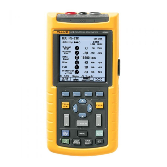
Page 58: Reading The Screen
Fluke 125 Users Manual Reading the Screen The bus test screen (see the example in figure 4-2) shows the status of the various signal properties. Information is represented in four columns: signal property that is being tested, for example VHigh. Rows 1 to 6 show each signal property and corresponding data.
-
Page 59
Field Bus Measurements Reading the Screen Property Explanation : bus activity indicators. VBias Bias voltage Bus activity indicator 1: CAN-Rec. H-L CAN-recessive high to low level voltage (filled) voltage measured CAN-Rec. H CAN-recessive high level voltage (open) no voltage measured CAN-Rec. -
Page 60
Fluke 125 Users Manual Figure 4-3 shows the bust health indicator boundaries. Table 4-4. F1…F4 Key Functions Example: Select the Limit Setup function, see page 4-8. the high level voltage of a bus must be between +3.0 V (MIN) and +15.0 V (MAX). Depending on the… -
Page 61: Viewing The Bus Waveform Screen
Field Bus Measurements Viewing the Bus Waveform Screen Viewing the Bus Waveform Screen To view the waveform eye pattern of the bus voltage, do the following: In the main screen select eye pattern mode. You will see a screen like figure 4-4. The screen shows the waveforms of one bit time triggered on a positive as well as on a negative edge in persistence mode.
-
Page 62: Setting The Test Limits
Fluke 125 Users Manual Setting the Test Limits Change the limits. You can change the test limits used to generate the A * in the SETUP LIMITS screen messages OK , WARNING , and NOT OK indicates that a signal property has limits that differ from the The test limits apply to the selected bus type.
-
Page 63: Saving And Recalling Test Limits
Field Bus Measurements Saving and Recalling Test Limits Saving and Recalling Test Limits You can save a screen, plus the test setup with (adjusted) test limits, plus the most recent eye pattern trace as a new dataset. By recalling this dataset you can do a bus test according to your own pre-defined test limits.
-
Page 64
Fluke 125 Users Manual 4-10… -
Page 65: Plotting Measurements Over Time (Trendplot Tm )
Chapter 5 Plotting Measurements over Time (TrendPlot Introduction Starting/Stopping a TrendPlot The TrendPlot™ function plots a graph derived from the To start a TrendPlot™ do the following: MAIN (large) readings in the SCOPE/METER mode or in Open the application mode menu. the HARMONICS mode as a function of time.
-
Page 66
Fluke 125 Users Manual The test tool continuously logs all readings to memory and Start the TrendPlot. You will see a displays these as graphs. If input A and input B are on, the screen like figure 5-1. upper graph belongs to input A. -
Page 67: Changing The Trendplot Reading
Plotting Measurements over Time (TrendPlotTM) Changing the TrendPlot Reading Changing the TrendPlot Reading Making TrendPlot Cursor Measurements To toggle the secondary TrendPlot reading between MIN Cursors allow you to make precise digital measurements (minimum), MAX (maximum), and AVERAGE, do the on the plotted graph(s).
-
Page 68
Fluke 125 Users Manual… -
Page 69: Saving And Recalling Data Sets
Chapter 6 Saving and Recalling Data Sets Introduction Saving Data Sets This Chapter explains how to save data sets into the test To save a data set do the following: tool’s Flash EEPROM memory and how to view, rename Open the SAVE/RECALL mode. and delete them.
-
Page 70
Fluke 125 Users Manual If no free memory locations are available message pops Open the SAVE … submenu. up that proposes to you to overwrite the oldest data set. Do one of the following: Reject the proposal to overwrite the oldest data set, then delete one or more memory locations, and save again. -
Page 71: Recalling, Renaming, Deleting Data Sets
Saving and Recalling Data Sets Recalling, Renaming, Deleting Data Sets Recalling, Renaming, Deleting Data Sets Press F1 to delete the data set To recall a data set, do the following: Press F2 to rename the data set; Open the SAVE/RECALL mode. do steps 3…5 of the ‘Saving Data Sets procedure.
-
Page 72
Fluke 125 Users Manual… -
Page 73: Using A Printer And Flukeview
Chapter 7 Using a Printer and FlukeView Introduction Using a Printer This Chapter explains how to setup the test tool for To print a (graphic) hard copy of the present screen, you communication with : need to use one of the following: a printer to make a hardcopy of the test tool screen The Optically Isolated RS-232 Adapter/Cable (PM9080, optional) to connect a serial printer to the…
-
Page 74
Fluke 125 Users Manual This example covers how to set up the test tool to print on a HP Deskjet printer with a baud rate of 9600 baud: Open the USER OPTIONS menu. Highlight PRINTER SETUP… Figure 7-1. Connecting a Serial Printer Open the PRINTER SETUP submenu. -
Page 75: Using Flukeview Software
Using a Printer and FlukeView Using FlukeView® Software To print a screen, do the following: ® Using FlukeView Software Open the SAVE&PRINT menu. To connect the test tool to a computer for using the Observe that the screen is frozen. ®…
-
Page 76
Fluke 125 Users Manual… -
Page 77: Maintaining The Test Tool
Chapter 8 Maintaining the Test Tool Introduction Cleaning the Test Tool This chapter covers basic maintenance procedures that Clean the test tool with a damp cloth and a mild soap to can be performed by the user. For complete service, avoid abrasion of text on the test tool.
-
Page 78: Charging The Rechargeable Battery Pack
Fluke 125 Users Manual Charging the Rechargeable Battery Pack At delivery, the batteries may be empty and must be charged to fill them completely. Charging time is 7 hours (test tool is off). When fully charged, the batteries typically provide 6 hours of use at full brightness. Operating time is extended at normal brightness.
-
Page 79: Keeping Batteries In Optimal Condition
Maintaining the Test Tool Keeping Batteries in Optimal Condition Keeping Batteries in Optimal Condition To refresh the battery pack, do the following: • Be sure that the test tool is line powered. Always operate the test tool on batteries until an -icon appears on the bottom line of the screen.
-
Page 80: Replacing And Disposing Of The Rechargeable Battery Pack
Used batteries should be disposed of by a qualified recycler or hazardous materials handler. Contact your authorized FLUKE Service Center for recycling information. To replace the battery pack, do the following: (See Figure 8-2.)
-
Page 81: Using And Adjusting 10:1 Scope Probes
Using and Adjusting 10:1 Scope Probes Note The 10:1 voltage probe VPS40 that is supplied BB120 with Fluke 125 is always adjusted correctly to the Test Tool and needs no further adjustment. You need to adjust other 10:1 scope probes for optimal response.
-
Page 82
Fluke 125 Users Manual Open the application mode menu. A square wave appears on the screen. Highlight SCOPE/METER Adjust the trimmer screw in the probe housing to give an optimum Enter the SCOPE/METER mode. square wave. Open the Input A or the Input B MEASUREMENTS menu. -
Page 83: Specifications
Parts and Accessories Open the VERSION&CALIBRATION Service Manual submenu. A service manual can downloaded from Fluke’s website www.fluke.com Standard Accessories The next tables list the user-replaceable parts for the various test tool models. To order replacement parts, contact your nearest service center.
-
Page 84
National Requirements must be used. Set of two Shielded Test Leads (Red and Gray), designed for use only STL120 with the Fluke ScopeMeter 120 series test tool. Set contains the following replaceable part: Ground Lead with Alligator Clip (Black) -
Page 85
Standard Accessories (cont) Item Ordering Code Test Lead for Grounding (Black) TL75 (red + black lead) Set of three Alligator Clips (Red, Gray, and Black) AC120 Banana-to-BNC Adapter (Black). BB120 (set of two) Note: manuals can be downloaded from Fluke’s website www.fluke.com… -
Page 86: Optional Accessories
Fluke 125 Users Manual Optional Accessories Item Ordering Code Software & Cable Carrying Case Kit (Supplied with Fluke 125/S) SCC 120 Set contains the following parts: Optically Isolated RS-232/USB Adapter/Cable OC4USB Hard Carrying Case. Supplied with Fluke 125/S C120 ®…
-
Page 87: Tips And Troubleshooting
Chapter 9 Tips and Troubleshooting Introduction This Chapter gives you information and tips on how you can make the best use of the test tool. Using the Tilt Stand The test tool is equipped with a tilt stand, allowing viewing from an angle.
-
Page 88: Changing The Information Language
Fluke 125 User Manual Changing the Information Language Setting the Grid Display When you operate the test tool, messages appear on the To choose a dotted grid, do the following: screen. These messages are always displayed in a box, Open the USER OPTIONS menu.
-
Page 89: Changing Date And Time
Tips and Troubleshooting Changing Date and Time Changing Date and Time Jump to DAY. The test tool has a date and time clock. To change the Choose 20. date to (e.g.) 20 June, 2007, do the following: Jump to FORMAT. Open USER OPTIONS menu.
-
Page 90: Saving Battery Life
Fluke 125 User Manual Saving Battery Life Open the submenu. When operated on the battery pack (no Power Adapter connected), the test tool conserves power by shutting itself down. If you have not pressed a key for at least 30 minutes, the test tool turns itself off automatically.
-
Page 91: Changing The Auto Set Options
Tips and Troubleshooting Changing the Auto Set Options Changing the Auto Set Options Highlight SIGNAL > 1 Hz. On delivery or after a reset , the Auto Set function Accept the new Auto Set captures waveforms from 15 Hz and faster and sets the configuration.
-
Page 92: Using Proper Grounding
Fluke 125 User Manual Using Proper Grounding Incorrect grounding can cause various problems. This Section gives you guidelines for proper grounding. Use the short ground lead(s) when measuring DC or AC signals on input A and input B. (See Figure 9-2.)
-
Page 93: Solving Printing And Other Communication Errors
Solving Printing and Other Communication Errors Solving Printing and Other Battery Testing of Fluke Accessories Communication Errors When using battery operated Fluke accessories, always check the battery condition of the accessory first on a RS-232 communication may cause problems. When Fluke multimeter.
-
Page 94
Fluke 125 User Manual… -
Page 95: Specifications
Safety Characteristics The test tool has been designed and tested in accordance Performance Characteristics with Standards ANSI/ISA-82.02.01, EN 61010-1: 2001, FLUKE guarantees the properties expressed in numerical CAN/CSA-C22.2 No.61010-1-04 and UL no. 61010-1-04 values with the stated tolerance. Specified non-tolerance (including…
-
Page 96: Dual Input Oscilloscope
Fluke 125 Users Manual Dual Input Oscilloscope Input Impedance excluding probes and test leads ….1 MΩ//12 pF Vertical with BB120 ……….1 MΩ//20 pF with STL120 ……….1 MΩ//225 pF Frequency Response with VP40 10:1 Probe……5 MΩ//15.5 pF DC Coupled: Sensitivity ……….. 5 mV to 500 V/div excluding probes and test leads (via BB120): ….
-
Page 97
Specifications Dual Input Oscilloscope Horizontal Trigger Scope Modes……..Normal, Single, Roll Screen Update …….Free Run, On Trigger Ranges Source …………..A, B, EXT Normal: EXTernal via optically isolated trigger probe ITP120 equivalent sampling ……10 ns to 500 ns/div (optional accessory) real time sampling ……..1 μs to 5 s/div Sensitivity A and B Single (real time) ……..1 μs to 5 s/div… -
Page 98: Dual Input Meter
Fluke 125 Users Manual Advanced Scope Functions Dual Input Meter Display Modes The accuracy of all measurements is within ± (% of Normal ..Captures up to 40 ns glitches and displays reading + number of counts) from 18 °C to 28 °C.
-
Page 99
Specifications Dual Input Meter AC or DC coupled: Frequency Range in Continuous Autoset …… 60 Hz to 20 kHz……±(2.5% +15 counts) 15 Hz (1 Hz) to 50 MHz 20 kHz to 1 MHz……±(5% +20 counts) Accuracy: 1 MHz to 5 MHz……±(10% +25 counts) @1 Hz to 1 MHz …… -
Page 100
Fluke 125 Users Manual Amperes (AMP) ……..with current clamp Power Ranges ..same as VDC, VAC, VAC+DC, or PEAK Configurations ………..1 phase Scale Factors ..0.1 mV/A, 1 mV/A, 10 mV/A, 100 mV/A, ……3 phase 3 conductor balanced loads 400 mV/A, 1 V/A, 10 mV/mA (3 phase: fundamental component only, Accuracy .. -
Page 101
Specifications Dual Input Meter Input A Diode Measurement Voltage: Ohm (Ω) @0.5 mA …………>2.8V Ranges……50Ω, 500Ω, 5 kΩ, 50 kΩ, 500 kΩ, @open circuit…………<4V …………. 5 MΩ, 30 MΩ Accuracy……….±(2% +5 counts) Accuracy: ……… ±(0.6% +5 counts) Measurement Current………0.5 mA ………50 Ω… -
Page 102: Cursor Readout
Fluke 125 Users Manual Advanced Meter Functions Cursor readout Sources: Zero Set A, B Set actual value to reference Single Vertical Line: Fast/Normal/Smooth Average, Min and Max Readout Meter settling time Fast: 1s @ 1 μs to 10 ms/div. Average, Min, Max and Time from Start of Readout (in Meter settling time Normal: 2s @ 1 μs to 10 ms/div.
-
Page 103: Harmonics Measurements
Specifications Harmonics Measurements Harmonics Measurements Field Bus Measurements Number of Harmonics Type Subtype Protocol …………DC..33 (< 60 Hz) AS-i NEN-EN50295 …………DC..24 (400 Hz) ISO-11898 Readings / Cursor readings (fundamental 40…70 Hz) V rms / A rms ……fund. ±(3 % + 2 counts) Interbus S RS-422 EIA-422…
-
Page 104: Miscellaneous
Fluke 125 Users Manual Miscellaneous Memory Number of Data set Memories ……..20 Display Mechanical Size……..72 x 72 mm (2.83 x 2.83 in) Size …….232 x 115 x 50 mm (9.1 x 4.5 x 2 in) Resolution ……….240 x 240 pixels Weight …………
-
Page 105: Environmental
Specifications Environmental Environmental Electromagnetic Compatibility (EMC) Emission and Immunity ….EN/IEC61326-1: 2006 Environmental ……. MIL-PRF-28800F, Class 2 Temperature Operating …….. 0 to 50 °C (32 to 122 °F) Enclosure Protection ….IP51, ref: EN/IEC60529 Storage ………-20 to 60 °C (-4 to 140 °F) Safety Humidity Operating:…
-
Page 106
Fluke 125 Users Manual Figure 10-1. Max. Input Voltage v.s. Frequency for Figure 10-2. Max. Input Voltage v.s. Frequency for BB120 and STL120 VP40 10:1 Voltage Probe 10-12… -
Page 107
Specifications Safety The Fluke 125, including standard accessories, conforms with the EEC directive 2004/108/EC for EMC immunity, as defined by EN61326-1: 2006, with the addition of the following tables. Trace disturbance with STL120 Table 1 No visible disturbance E= 3 V/m… -
Page 108
Fluke 125 Users Manual Multimeter disturbance: • VDC, VAC, and VAC+DC with STL120 and short ground lead. • OHM, CONT, DIODE, and CAP with STL120, and black test lead to COM. Table 3 Disturbance less than 1% of full scale… -
Page 109: Appendices
Appendices Appendix Title Page Bushealth Measurements ………………… A-1…
-
Page 111: Bushealth Measurements
This Appendix contains information to extend the The Bushealth measurement is based upon the information presented in the Fluke 125 Users Manual. instrument’s Scope mode. In Scope mode the instrument displays the waveforms of the bus signals. Once a signal This concerns Chapter 4 –…
-
Page 112: Use Of Probes And Accessories
Use of Probes: refer to page 0-2 and 0-3 of this Manual system under test. for an overview of accessories as suplied with Fluke 125. You can use the optional BHT190 Bushealth Test adapter For most measurements the Shielded Test Leads to connect the probe tip in an easy way to busses that STL120 (1:1) are used.
-
Page 113: Tips And Hints Per Bustype
Appendices Bushealth Measurements For Bus measurements that use input A and B (CAN, Connection between controller and devices is made using Modbus RS-485, Profibus DP, RS-485) it is important that a dedicated yellow flat cable as shown in the figure below the Common Mode component at the inputs is as small (cross section).
-
Page 114: Can Bus/Devicenet
Fluke 125 Users Manual 3.5 V 1: Ch. A (+) CAN_H Connect to Ch. A 2.5 V CAN_L 3: COM (-) Connect M12 CONNECTOR (FEMALE) to Ch. B CAN Bus/DeviceNet 1.5 V Ground The Controller Area Network (CAN) is used on board of Connect automobiles and also in industrial applications.
-
Page 115: Interbus S
Appendices Bushealth Measurements automobile manufacturers leave bus signals at the connector default on, other manufacturers require bus signals to be enabled via an external controller. DEVICE 1 CONTROLLER DEVICE N DB-9 (FEMALE) 1 OBD2 (FEMALE) 8 To check Interbus S, ScopeMeter Channel A is on and DC coupled.
-
Page 116: Modbus Iea-232/Rs-232
Fluke 125 Users Manual below shows a typical system layout. Data traffic is continuous. DEVICE 1 DEVICE 2 COAX COAX COAX PASSIVE PASSIVE PM9083 BB120 To check ControlNet, ScopeMeter Channel A is on and DC coupled. The recommended Banana to BNC Adapter BB120 (1:1) allows Channel A to connect with BNC Modbus IEA-232/RS-232.
-
Page 117: Modbus Iea-485/Rs-485
Appendices Bushealth Measurements they can be measured as well as far as V-Levels are Foundation Fieldbus H1 31.25 kBits/s concerned. Is used to control ‘field equipment’ such as sensors, actuators, valves, and I/O devices via a two-wire Tx: Connect to Ch. A connection.
-
Page 118: Profibus Dp
Fluke 125 Users Manual below. Please note that cables often incorporate termination resistors at the end of the network chain. CHANNEL A GREEN Profibus DP/RS-485 CHANNEL B Profibus DP (Decentralized Periphery) is an open Fieldbus standard used in Process Industry and Factory Automation.
-
Page 119: Profibus Pa/31.25 Kbits/S
Appendices Bushealth Measurements A: Data+ and Pwr B: Data- and Pwr C: Optional Pwr+ D: Optional Pwr- Profibus PA/31.25 kBits/s Caution When planning tests on this bustype, make Profibus PA (Process Automation) is optimized for sure the proper safety rules are adhered to! process control with focus on explosion safety.
-
Page 120: Ethernet Twisted Pair/10Baset
Fluke 125 Users Manual DEVICE 1 DEVICE 2 CABLE COAX COAX COAX PASSIVE PASSIVE PM9083 BB120 The wires can be reached with Back Probe Pins TP88 (optional) at screw terminals at a device’s wire entry point: for instance at a Junction Box. The right-hand figure shows pinning and wire colors of a RJ-45 connector.
-
Page 121: Rs-232 Bus
Appendices Bushealth Measurements RS-232 Bus RS-232 allows two-way communication between a controller and a device such as modem, printer, or sensor. Per device a dedicated link is needed. Initially the RS-232 definition offered an extensive handshake protocol with separate handshake lines (hardware handshake);…
-
Page 122: Overview Of Female Db-Connectors
Fluke 125 Users Manual CONTROLLER DEVICE 1 DEVICE 2 Gnd. Connect to Ch. A Connect to Ch. B Connect to COM Overview of Female DB-connectors A-12…
-
Page 123
Index Amperes Measurement, 10-6 Battery Power, 10-10 Amplitude, 2-10 battery refresh, 8-3 —1— Auto Set, 2-3, 10-4 Battery Refresh Date, 8-7 Auto Set Configuration, 9-5 Battery Replacing, 8-4 Auto/Manual, 2-10 BB120 Adapters, 8-9 1 Probe, 2-25 Automatic Power Shutdown, 9-4 Blue Function Keys, 2-2 Avoid Electrical Shock, 1-5 BP120MH Battery Pack, 8-8… -
Page 124
Fluke 125 Users Manual Caution, 0-4 Declaration of Conformity, 0-1 FREE RUN, 2-19 Changing the Amplitude, 2-10 Deleting Data Sets, 6-3 Freeze Recording, 2-15 Changing the Time Base, 2-10 Dimmed Display, 1-3 Freezing the Screen, 2-8 Charge Time, 10-10 Diode, 9-6, 10-7… -
Page 125
Index (continued) —M— —O— Horizontal Move, 10-3 Humidity, 10-11 Maintenance, 8-1 OC4USB, 3, 8-10 Hz, 10-5 Making Measurements, 2-4 Ohm (Ω), 9-6, 10-7 Manual, 8-9 Operating Time, 10-10 —I— Manual Override, 10-4 Optical Interface, 1, 3, 10-10 Manual Ranges, 2-10 Information Language, 9-2 Max. -
Page 126
Fluke 125 Users Manual Probe 10 RPM, 10-5 Specifications, 10-1 1, 2-25 RS-232 Adapter/Cable, 1, 8-10 Stable Reading, 2-8 Probe Adjustment, 2-25 RS-232 Communication Errors, 9-7 Stand, 9-1 Probe Attenuation, 2-25 RS-232/USB Adapter/Cable, 3 STL120 Test Leads, 8-8 Probe Settings, 1-6… -
Page 127
Index (continued) —Z— Trigger Parameters, 2-18 Trigger Sensitivity, 10-3 Zero Reference, 2-9 Triggering, 2-17 True RMS Voltages, 10-4 —U— Unpacking, 0-2 USB Adapter/Cable, 8-10 User Manual, 8-9 Using a Printer, 1 Using FlukeView Software, 3 —V— Vertical Accuracy, 10-2 Vertical Cursors, 2-23 Vibration, 10-11 Video Line, 2-21 Video on A, 10-3… -
Page 128
Fluke 125 Users Manual…
Руководства Fluke FLUKE 125 007 Размер файлов: 1314 KB, Язык: English, Формат: pdf, Платформа: Windows/Linux, Дата: 2016-11-07
На данной странице вы можете скачать руководства Fluke FLUKE 125 007. Мы предлагаем вам ознакомиться с руководством пользователя, инструкцией по сервисному обслуживанию и ремонту.
Также здесь вы найдете список заказных номеров на комплектующие Fluke FLUKE 125 007.
Все файлы предоставляются исключительно в ознакомительных целях. И не являютя руководством по ремонту, а направлены лишь на то чтобы помочь вам более детально ознакомиться с принципом построения устройства.
Содержимое представленных здесь руководств требуют от вас знания технического английского языка.
Если вы собираетесь скачать руководство по сервисному обслуживанию Fluke FLUKE 125 007, иными словами сервис мануал, вы дожны обладать хотя бы минимальными познаниями в области электроники и пониманием базовых принципов работы электромеханических устройств.
Для просмотра руководств вам понадобится Adobe Acrobat Reader версии 9 и выше либо другая программа для просмотра pdf файлов.
В связи с популярностью информации представленной на сайте и ее бесплатного предоставления конечному пользователю, убедительная просьба использовать специальные программные продукты для многопотокового скачивания файлов.
Руководства для Fluke FLUKE 125 007
- Руководство пользователя (User manual)
- Руководство по сервисному обслуживанию (Service manual)
- Руководство по ремонту (Repair manual)
- Перечень комплектующих (PartList)
Fluke 125 Область метр
Производитель:
Модель:
125
Дата:
2007
Категория:
Группа:
Описание:
Industrial ScopeMeter
Руководство по техническому обслуживанию
Hасто́льная кни́га тип:
Руководство по техническому обслуживанию

Страницы:
96
Размер:
1.99 Mbytes (2082892 Bytes)
Язык:
english
Пересмотр:
Hасто́льная кни́га ID:
4822 872 05398
Дата:
Качество:
Электронный документ, ни сканирование, очень хорошо читается.
Дата загрузки:
2014 11 29
MD5:
c87ad484e83e45f4a08037ec9a5bb2fb
Загрузки:
1914
Информация
Limited Warranty & Limitation of
Liability …
ii
Introduction and Safety
Instructions … 1-1
1.1 Introduction to Service Manual
…
1-3
1.2 Safety
…
1-3
1.2.1
Introduction …
1-3
1.2.2 Safety
Precautions …
1-3
1.2.3 Caution and Warning
Statements …
1-3
1.2.4 Symbols used in this Manual and on Instrument
… 1-4
1.2.5 Impaired
Safety …
1-4
1.2.6 General Safety
Information …
1-4
Characteristics
… 2-1
2.1
Introduction …
2-3
2.2 Dual Input
Oscilloscope …
2-3
2.2.1
Vertical …
2-3
2.2.2 Horizontal
…
2-4
2.2.3 Trigger
…
2-4
2.2.4 Advanced Scope
Functions …
2-5
2.3 Dual Input
Meter …
2-5
2.3.1 Input A and Input B
…
2-5
2.3.2 Input A
…
2-8
2.3.3 Advanced Meter Functions
…
2-9
2.4 Cursor Readout (Fluke 124,
125) …
2-10
2.5 Harmonics Measurements (Fluke
125) …
2-10
2.6 Field Bus Measurements (Fluke 125)
…
2-11
2.7 Miscellaneous
…
2-11
2.8
Environmental …
2-12
2.9 Service and Maintenance
…
2-13
2.10 Safety
…
2-13
2.11 EMC Immunity
…
2-15
Performance
Verification … 3-1
3.1
Introduction …
3-3
3.2 Equipment Required For Verification
… 3-3
3.3 How To
Verify …
3-4
3.4 Display and Backlight
Test …
3-4
3.5 Input A and Input B
Tests …
3-5
3.5.1 Input A and B Base Line Jump Test
… 3-6
3.5.2 Input A Trigger Sensitivity Test
…
3-8
3.5.3 Input A Frequency Response Upper Transition Point Test
… 3-9
3.5.4 Input A Frequency Measurement Accuracy Test
… 3-9
3.5.5 Input B Frequency Measurement Accuracy
Test … 3-10
3.5.6 Input B Frequency Response Upper Transition Point
Test … 3-11
3.5.7 Input B Trigger Sensitivity Test
…
3-12
3.5.8 Input A and B Trigger Level and Trigger Slope Test
… 3-13
3.5.9 Input A and B DC Voltage Accuracy Test
… 3-16
3.5.10 Input A and B AC Voltage Accuracy Test
… 3-18
3.5.11 Input A and B AC Input Coupling Test
… 3-19
3.5.12 Input A and B Volts Peak Measurements Test
… 3-20
3.5.13 Input A and B Phase Measurements Test
… 3-21
3.5.14 Harmonics (Fluke 125)
…
3-21
3.5.15 Input A and B High Voltage AC/DC Accuracy
Test … 3-22
3.5.16 Resistance Measurements Test
…
3-24
3.5.17 Continuity Function Test
…
3-25
3.5.18 Diode Test Function
Test …
3-26
3.5.19 Capacitance Measurements
Test …
3-26
3.5.20 Video Trigger
Test …
3-27
Calibration
Adjustment … 4-1
4.1
General …
4-3
4.1.1
Introduction …
4-3
4.1.2 Calibration number and
date …
4-3
4.1.3 General
Instructions …
4-3
4.2 Equipment Required For
Calibration …
4-4
4.3 Starting Calibration Adjustment
…
4-4
4.4 Contrast Calibration Adjustment
…
4-6
4.5 Warming Up &
Pre-Calibration …
4-7
4.6 Final Calibration
…
4-7
4.6.1 HF Gain Input A&B
…
4-7
4.6.2 Delta T Gain, Trigger Delay Time & Pulse Adjust Input
A … 4-9
4.6.3 Pulse Adjust Input B
…
4-10
4.6.4 Gain DMM (Gain Volt)
…
4-10
4.6.5 Volt
Zero …
4-12
4.6.6 Zero
Ohm …
4-12
4.6.7 Gain
Ohm …
4-13
4.6.8 Capacitance Gain Low and High
…
4-14
4.6.9 Capacitance Clamp &
Zero …
4-14
4.6.10 Capacitance Gain
…
4-15
4.7 Save Calibration Data and
Exit …
4-15
Disassembling the Test Tool
… 5-1
5.1.
Introduction …
5-3
5.2. Disassembling Procedures
…
5-3
5.1.1 Required
Tools …
5-3
5.2.2 Removing the Battery Pack
…
5-3
5.2.3 Removing the Bail
…
5-3
5.2.4 Opening the Test Tool
…
5-3
5.2.5 Removing the Main PCA
Unit …
5-5
5.2.6 Removing the Display
Assembly …
5-6
5.2.7 Removing the Keypad and Keypad Foil
… 5-6
5.3 Disassembling the Main PCA
Unit …
5-6
5.4 Reassembling the Main PCA
Unit …
5-8
5.5 Reassembling the Test
Tool …
5-8
List of Replaceable Parts
… 6-1
6.1
Introduction …
6-3
6.2 How to Obtain
Parts …
6-3
6.3 Service Centers
…
6-3
6.4 Final Assembly Parts
…
6-4
6.5 Main PCA Unit Parts
…
6-6
6.6 Service Tools
…
6-7
показать больше