-
Contents
-
Table of Contents
-
Troubleshooting
-
Bookmarks
Quick Links
Title
FLOWSIC600
Ultrasonic Gas Flow Meter
Ultrasonic Gas Flow Meter
for Custody Transfer
and Process Applications
MEPAFLOW600 CBM and Firmware V3.4.xx
O P E R A T I N G I N S T R U C T I O N S
Applifoto
74 x 45 mm
(150 dpi: 437 x 266 pixel)
x = 136 mm y = 58 mm
Related Manuals for SICK FLOWSIC600
Summary of Contents for SICK FLOWSIC600
-
Page 1
O P E R A T I N G I N S T R U C T I O N S Applifoto 74 x 45 mm (150 dpi: 437 x 266 pixel) FLOWSIC600 Ultrasonic Gas Flow Meter x = 136 mm y = 58 mm Ultrasonic Gas Flow Meter… -
Page 2
Physikalisch Technische Bundesanstalt (~ Federal Metrology Office in Germany) Remote Terminal Unit Signal Processing Unit Verband der Elektrotechnik Elektronik Infor- mationstechnik (~ Association of German Electrical Engineers) FLOWSIC600 · Operating Instructions · 8010458 V 2.0 · © SICK MAIHAK GmbH… -
Page 3
Information about the use in potentially explosive atmospheres Important technical information for this product Important information on electric or electronic func- tions Supplementary information Link to information at another place FLOWSIC600 · Operating Instructions · 8010458 V 2.0 · © SICK MAIHAK GmbH… -
Page 4: Table Of Contents
Operating the FLOWSIC600 in safe areas ……..
-
Page 5
Connecting the FLOWSIC600 to a PC or Laptop……. . . -
Page 6
Sealing Plan …………. . . 94 FLOWSIC600 · Operating Instructions · 8010458 V 2.0 · © SICK MAIHAK GmbH… -
Page 7: Important Information
General Safety Instructions and Protective Measures Dangers Due to Hot, Corrosive and Explosive Gases and High Pressure Dangers Due to Heavy Loads Environmental Information and Instructions for Disposal FLOWSIC600 · Operating Instructions · 8010458 V 2.0 · © SICK MAIHAK GmbH…
-
Page 8: About This Document
About this Document 1. 1 This manual describes the FLOWSIC600 measuring system, which is used to determine the volumetric flow rate, volume and the speed of sound in gases transported in pipelines. It provides general information on the measuring method employed, design and function of the entire system and its components, and on planning, assembly, installation, calibration commissioning, maintenance and troubleshooting.
-
Page 9: Safety Instructions
Do not expose the equipment to mechanical stress, such as pigging. ● The flooding of the FLOWSIC600 with any liquid (e.g. for pressure or leakage tests) is an ● improper use. The consequences of such activities can not be foreseen or estimated.
-
Page 10: General Safety Instructions And Protective Measures
European Pressure Equipment Directive 97/23/EC. All relevant information for the particular application (as specified in the technical information questionnaire filled out by the customer) has been taken into account before commencing order processing. FLOWSIC600 · Operating Instructions · 8010458 V 2.0 · © SICK MAIHAK GmbH…
-
Page 11: Dangers Due To Heavy Loads
Only the printed-circuit boards must be disposed of as electronic scrap. FLOWSIC600 · Operating Instructions · 8010458 V 2.0 · © SICK MAIHAK GmbH…
-
Page 12
Important Information FLOWSIC600 · Operating Instructions · 8010458 V 2.0 · © SICK MAIHAK GmbH… -
Page 13: Product Description
Product Description FLOWSIC600 Product Description System Components Operating States and Signal Output MEPAFLOW600 CBM FLOWSIC600 · Operating Instructions · 8010458 V 2.0 · © SICK MAIHAK GmbH…
-
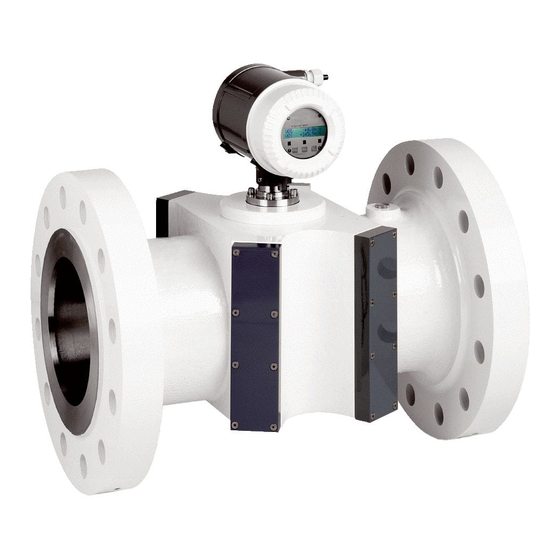
Page 14: System Components
Standard meter bodies are available in carbon steel, Low Temperature Carbon Steel and stainless steel. The meter bodies can be delivered in several nominal sizes (see → pg. 82, 7.1.3). FLOWSIC600 · Operating Instructions · 8010458 V 2.0 · © SICK MAIHAK GmbH…
-
Page 15: Ultrasonic Transducers
The electronics are mounted in the SPU enclosure certified to EN 60079-1 or IEC 60079-1 with protection type “d“ (flameproof enclosure). The transducer circuits are of an intrinsically safe design (category “ia“). FLOWSIC600 · Operating Instructions · 8010458 V 2.0 · © SICK MAIHAK GmbH…
-
Page 16: Operating Modes, Meter States And Signal Output
(transducer simulator). This function can only be activated if the system is in the “Configuration” mode. It is used to test a path-specific electronic module. Test cycles are automatically cancelled when leaving the “Configuration” mode. FLOWSIC600 · Operating Instructions · 8010458 V 2.0 · © SICK MAIHAK GmbH…
-
Page 17: Meter States
However, the SPU will cyclically try to re-establish valid measurements. As soon as the signal quality and number of valid measurements meet the required criteria, the SPU will automatically change back to the “Measurement valid” or “Check request” status. FLOWSIC600 · Operating Instructions · 8010458 V 2.0 · © SICK MAIHAK GmbH…
-
Page 18: Pulse Output And Status Information
Reg.#3034 “ErrorFreq“ (0-6 kHz). ** Default setting on delivery. *** Optional setting on customer request. The default setting for “Check request”, “Configuration” and “Measurement invalid” is “normally closed”. FLOWSIC600 · Operating Instructions · 8010458 V 2.0 · © SICK MAIHAK GmbH…
-
Page 19
Depending on the type of entry this will be: “I” for Information ● “W” for Warning ● “E” for Error ● After acknowledging all new entries, the flashing letter disappears. For details see → pg. 68, 5.4.1. FLOWSIC600 · Operating Instructions · 8010458 V 2.0 · © SICK MAIHAK GmbH… -
Page 20: Mepaflow600 Cbm
Installation A product CD containing the MEPAFLOW600 CBM software is included with the FLOWSIC600 when it is delivered. Insert the product CD into your CD-ROM drive to install the software. Start the file ‘FLOWSIC600_R_CD.exe‘ to install the software. Download from www.flowsic600.com MEPAFLOW600 CBM can be downloaded free of charge from the www.flowsic600.com…
-
Page 21: Overview
2.3.2 The MEPAFLOW600 CBM software supplies a menu-based user interface with many features for the diagnosis of the FLOWSIC600 system. It allows the access of all system parameters, displays diagnostic information in charts and graphs, generates reports (i.e. Maintenance reports) and data files (records, logs) which can be exported and can be used for data analysis.
-
Page 22
Product Description FLOWSIC600 · Operating Instructions · 8010458 V 2.0 · © SICK MAIHAK GmbH… -
Page 23: Installation
Installation FLOWSIC600 Installation General Notes Installation Mechanical Installation Electrical Installation FLOWSIC600 · Operating Instructions · 8010458 V 2.0 · © SICK MAIHAK GmbH…
-
Page 24: General Notes
Delivery 3.1.1 The FLOWSIC600 is delivered in a pre-assembled condition in a sturdy package. When unpacking the device, check for possible damage in transit. Pay particular attention to the interior of the meter body, any visible transducer components and the sealing surfaces on the flanges.
-
Page 25: Transport And Storage
Max. load information can be found on the type plate of the lifting gear. It is strongly recommended to use only the eye bolts when lifting the meter by itself. To lift the FLOWSIC600 please pay attention to Fig. 5.2.
-
Page 26: Installation
Measuring location 3.2.1 General requirements: The FLOWSIC600 can be installed in customary straight inlet and outlet pipes. The ● adjacent pipes must have the same nominal size as the meter body. The max. variation of the internal diameter of the inlet pipe from that of the meter body is 1%. Any welding beads and burs on the flanges of the inlet pipe shall be removed.
-
Page 27: Installation Configurations
1.5 .. 5 DN Configuration 1 ≥ 5 DN ≥ 3 DN min. 2 DN min. 2 DN 1.5 .. 5 DN Configuration 2 Flow conditioner Temperature measuring point FLOWSIC600 · Operating Instructions · 8010458 V 2.0 · © SICK MAIHAK GmbH…
-
Page 28
Two straight pipes shall be installed in the inlet and outlet sections if the meter is to be used bidirectionally. The temperature measuring point shall be disposed downstream the FLOWSIC600, seen in the direction of predominant use (position 1 or 2 in → Figure 7). Figure 7 FLOWSIC600 installation in the pipeline for bidirectional use ≥… -
Page 29: Mechanical Installation
Pressure Equipment Directive 97/23/EC. Installation staff must be familiar with the directives and standards ● applicable for pipeline construction. FLOWSIC600 · Operating Instructions · 8010458 V 2.0 · © SICK MAIHAK GmbH…
-
Page 30: Mounting The Flowsic600 In The Piping
An arrow on the meter body indicates the main direction of flow. It is recommended to install the FLOWSIC600 as indicated by this arrow if the meter is to be used for unidirectional flow applications. If the meter is to be used in the bidirectional mode, the arrow indicates the positive direction of flow.
-
Page 31: Spu Alignment
Loosen the hexagon Position the SPUTighten the hexagon socket head screw socket head screw NOTICE: Do not forget to tighten the hexagon socket head screw after positioning the SPU. FLOWSIC600 · Operating Instructions · 8010458 V 2.0 · © SICK MAIHAK GmbH…
-
Page 32: Electrical Installation
Pre-requisites Wiring work (routing and connecting the power supply and signal cables), which is necessary when installing the FLOWSIC600, is not included in the scope of delivery. The mechanical installation described in Section → 3.3 must be completed first. Comply with the minimum cable specification requirements set out in Section → 3.4.2.
-
Page 33
Service PC / higher- (Ex i isolating transformer only level control system required for intrinsically safe 12 … 24 V DC installation) Safe area Hazardous area FLOWSIC600 FLOWSIC600 · Operating Instructions · 8010458 V 2.0 · © SICK MAIHAK GmbH… -
Page 34: Cable Specifications
1000 m at 0,75 mm² (1500 ft for 20 pairs and prevent them from AWG) accidental short-circuit. Cable diameter 6 … 12 mm (1/4 to 1/2 inch) Fixing range of the cable glands FLOWSIC600 · Operating Instructions · 8010458 V 2.0 · © SICK MAIHAK GmbH…
-
Page 35: Checking The Cable Loops
Incorrect cabling may cause failure of the FLOWSIC600. This will invalidate ● warranty claims. The manufacturer assumes no liability for consequential damage. FLOWSIC600 · Operating Instructions · 8010458 V 2.0 · © SICK MAIHAK GmbH…
-
Page 36: Terminal Enclosure On The Spu
4 x 2 x 0.5 mm core cable (Li2YCY [TP] or equivalent) 10-pole terminal block MODBUS for signal inputs and outputs 4 x 2 x 0.5 mm (Li2YCY [TP] or equivalent) FLOWSIC600 · Operating Instructions · 8010458 V 2.0 · © SICK MAIHAK GmbH…
-
Page 37
Terminal assignment for use in safe areas Terminals 2 and PE are bridged internally, i.e. there is no insulation between PE and negative potential (see → Figure 11). FLOWSIC600 · Operating Instructions · 8010458 V 2.0 · © SICK MAIHAK GmbH… -
Page 38: Operating The Flowsic600 In Safe Areas
“Direction of flow” (default) (alternative “Warning”) Alternative assignment with second 9600 Baud, 8 data bits, no parity, 1 stop bit Baud rate to be set serial port (RS485) through software FLOWSIC600 · Operating Instructions · 8010458 V 2.0 · © SICK MAIHAK GmbH…
-
Page 39: Operation In Hazardous Areas (Directive 94/9/Ec (Atex)
The power supply and field connections are designed with the increased type of protection (“e“). The transducer connections are of an intrinsically safe design (“ia“). All screw-type terminals as well as air gaps and creepage distances of the FLOWSIC600 comply with EN 60079-7.
-
Page 40
After deinstallation and before every reinstallation the sealings must be renewed according to the original assembly. Sealings can be ordered from SICK (provide article number and serial number from type plate). -
Page 41
Aux. power Power supply Signal processing unit Digital output (SPU) RS485 Pressure-resistant Digital output space “d” Field connections Digital output Digital output Meter body Ultrasonic transducers “ia” FLOWSIC600 · Operating Instructions · 8010458 V 2.0 · © SICK MAIHAK GmbH… -
Page 42
= ±59 mA only) = 1399 mW = 556 mW = 556 mW Internal capacity: negligible negligible negligible Internal inductance: = 20.6 mH = 15.5 mH = 6.7 mH FLOWSIC600 · Operating Instructions · 8010458 V 2.0 · © SICK MAIHAK GmbH… -
Page 43: Commissioning
General Notes Connecting the FLOWSIC600 to a PC or Laptop Connecting to the FLOWSIC600 with MEPAFLOW600 CBM Identification Field Setup Function Test Activation of Path Compensation Sealing FLOWSIC600 · Operating Instructions · 8010458 V 2.0 · © SICK MAIHAK GmbH…
-
Page 44: General Notes
Parameter write lock has to be agreed to by the applicable national authorities. In all other cases the output parameters of the FLOWSIC600 can be adapted on site by trained staff. Commissioning the FLOWSIC600 involves the following steps, no matter whether the device is installed at a test facility or at the final measuring location: Connecting the FLOWSIC600 to a PC or Laptop (→ pg. 45, 4.2)
-
Page 45: Connecting The Flowsic600 To A Pc Or Laptop
Connecting the FLOWSIC600 via RS485 / RS232 cable 4.2.1 Interface sets for the connection of the FLOWSIC600 with a PC via serial- or USB-interface can be ordered from SICK. See → pg. 46, Table 3. The FLOWSIC600 serial interface conforms with the RS485 standard. An RS485 /RS232 cable and a 1:1 interface cable (pin 2 –…
-
Page 46: Connecting The Flowsic600 Via Rs485/Usb Converter
USB converter is necessary to transform the signal for the RS485 device interface. The USB converter available through SICK contains a CD-ROM with a software driver which must be installed before an online connection between the FLOWSIC600 and the MEPAFLOW600 CBM software can be established.
-
Page 47: Connecting To The Flowsic600 With Mepaflow600 Cbm
4.3.1 The MEPAFLOW600 CBM software is provided on the product CD shipped with the meter. It can also be downloaded from www.flowsic600.com. See → pg. 20, 2.3.1 for more details on the installation. After successful installation, start the MEPAFLOW600 CBM by selecting the “MEPAFLOW600 CBM”…
-
Page 48: Choosing An User Access Level
Create a new meter entry in the meter database by clicking the “New” button. Then follow the instructions on screen. FLOWSIC600 · Operating Instructions · 8010458 V 2.0 · © SICK MAIHAK GmbH…
-
Page 49: Online Connection: Direct Serial
COM port which has to be individually configured. After the connection has been established, MEPAFLOW600 CBM displays the start page (can be specified in the Program settings) and the current readings from the meter. FLOWSIC600 · Operating Instructions · 8010458 V 2.0 · © SICK MAIHAK GmbH…
-
Page 50: Online Connection: Ethernet
Commissioning Online Connection: Ethernet 4.3.5 The FLOWSIC600 can be connected to a network via Ethernet with an according adapter. This adapter translates the meter MODBUS communication (ASCII or RTU) to MODBUS TCP. MEPAFLOW600 CBM supports the MODBUS TCP protocol. Requirements The Ethernet connection requires firmware V3.3.05 or higher installed on…
-
Page 51
“MODBUS TCP to MODBUS ASCII/RTU Converter“, Model MES1b by B&B Electronics. This adapter is shipped with a software, which searches the network for connectable devices and supplies the user with the according IP addresses. FLOWSIC600 · Operating Instructions · 8010458 V 2.0 · © SICK MAIHAK GmbH… -
Page 52: Identification
NOTICE: Type Approval If the FLOWSIC600 is used for fiscal metering, the approved firmware versions and the associated check sums are documented in the national pattern approval certificates. FLOWSIC600 · Operating Instructions · 8010458 V 2.0 · © SICK MAIHAK GmbH…
-
Page 53: Field Setup
NAMUR (8,2V / 0,8…6,6mA) Painting Grey white (RAL9002)/grey (RAL7012) sta Switching state normally open Pressure tapping 1/4″ NPTF DO3 Clamp 81/82(RS485) SICK_MODBUS_ASCII TRANSDUCER Transcucer material (wetted) Titanium FLOWSIC600 · Operating Instructions · 8010458 V 2.0 · © SICK MAIHAK GmbH…
-
Page 54: Disconnecting From The Meter And Closing The Session
Click the “Disconnect“ button. The “Session description“ window opens. Describe the activies you carried out during the session (e.g. “Field Setup“). Click the “OK“ button. FLOWSIC600 · Operating Instructions · 8010458 V 2.0 · © SICK MAIHAK GmbH…
-
Page 55: Function Test
30 seconds after the power supply is switched on. If the yellow LED flashes, the FLOWSIC600 works in the operation state ’’Check request’’ with an insignificantly reduced accuracy (e.g. if one path fails). If the yellow LED lights up permanently, the measurement is invalid. In this case, you must diagnose the error (see Chapter 8 of this Manual).
-
Page 56: Function Test With Mepaflow600 Cbm
Figure 22 “Path Diagnosis” wizard in MEPAFLOW600 CBM Main system FLOWSIC600 · Operating Instructions · 8010458 V 2.0 · © SICK MAIHAK GmbH…
-
Page 57
Figure 25). If a lamp for “Time plausibility” is on, it indicates an incorrect zero phase. Figure 23 Signal window displaying ultrasonic signal in the “Path Diagnosis” page FLOWSIC600 · Operating Instructions · 8010458 V 2.0 · © SICK MAIHAK GmbH… -
Page 58
Commissioning Go to the “Meter values” page to check that the measured SOS values are almost the same at all paths of the FLOWSIC600, and that they differ by less then 0.1% (→ Figure 24). Switch between display of absolute and difference SOS by clicking the right mouse button on the SOS graph and using the context-menu. -
Page 59: Activation Of Path Compensation
Activation of Path Compensation 4 . 7 If the status bit “Path compensation valid” is “active”, then the FLOWSIC600 is able to compensate a path failure. The meter automatically sets this bit to “active” after operating for about 20 minutes with error free measurement at all paths at a gas velocity between 1 to 8m/s (3 to 25ft/s) and also about 20 minutes at a gas velocity higher than 8m/s (25ft/s).
-
Page 60: Sealing
Commissioning Sealing 4. 8 After having completed the commissioning, seal the signal processing unit (if required) in accordance with the sealing plan (see Section → pg. 94, 7.5). FLOWSIC600 · Operating Instructions · 8010458 V 2.0 · © SICK MAIHAK GmbH…
-
Page 61: Maintenance
Maintenance FLOWSIC600 Maintenance General Routine Checks Maintenance Report Optional Data Download FLOWSIC600 · Operating Instructions · 8010458 V 2.0 · © SICK MAIHAK GmbH…
-
Page 62: General
→ »Comparing theoretical and measured Speed of Sound (SOS)« (pg. 63) → »Checking the Meter Health« (pg. 64) → »Time Synchronization« (pg. 65) → »Battery Lifetime / Capacity« (pg. 66) Documentation: → »Maintenance Report« (pg. 67) FLOWSIC600 · Operating Instructions · 8010458 V 2.0 · © SICK MAIHAK GmbH…
-
Page 63: Routine Checks
Routine Checks 5 . 2 The information displayed on the front panel LCD display of the FLOWSIC600 meter can be checked to ensure that the system is functioning properly. The MEPAFLOW600 CBM software provides a more user friendly way for doing routine checks.
-
Page 64: Checking The Meter Health
Checking the Meter Health 5.2.2 The FLOWSIC600 monitors its own meter health with User Warnings and system alarms. If the outputs are configured to indicate alarms and / or User Warnings, it is not necessary to manually check the meter health.
-
Page 65: Time Synchronization
Synchronization via MODBUS The date and the time of the FLOWSIC600 can be set separately by an external write. Each operation for date and time causes a separate entry in the Custody logbook [1]. Alternatively the synchronization function can be used. To use this method, the date register (#5007) and the time register (#5008) have to be written sequentially within 2 seconds.
-
Page 66: Battery Lifetime / Capacity
Battery Lifetime / Capacity 5.2.4 The Real Time Clock (RTC) of the FLOWSIC600 is buffered by a battery with a guaranteed life span of 10 years. The remaining battery capacity can be viewed on the LCD in the first menu level (see Technical Information).
-
Page 67: Maintenance Report
“Meter explorer” and the “Report manager”. The Maintenance report can also be exported to Excel using the direct link provided when the Maintenance report is displayed. FLOWSIC600 · Operating Instructions · 8010458 V 2.0 · © SICK MAIHAK GmbH…
-
Page 68: Optional Data Download
The logbook entries are now downloaded to your MEPAFLOW600 CBM database. You can view them offline without connection to the meter or share them with others (export the device or the session). FLOWSIC600 · Operating Instructions · 8010458 V 2.0 · © SICK MAIHAK GmbH…
-
Page 69
If the Parameter write lock was unlocked prior to clearing the meter logbook, follow all necessary procedures to bring the meter to back to its original state. FLOWSIC600 · Operating Instructions · 8010458 V 2.0 · © SICK MAIHAK GmbH… -
Page 70
Maintenance FLOWSIC600 · Operating Instructions · 8010458 V 2.0 · © SICK MAIHAK GmbH… -
Page 71: Troubleshooting
Troubleshooting FLOWSIC600 Troubleshooting General Troubleshooting Indication of Meter States, System Alarms and Warnings Generation of Diagnosis Session Meter Connection Troubleshooting FLOWSIC600 · Operating Instructions · 8010458 V 2.0 · © SICK MAIHAK GmbH…
-
Page 72: General Troubleshooting
If the cause of the problem cannot be localized, it is recommended to use the MEPAFLOW600 CBM software to record the current parameter set and diagnosis values in a diagnosis session file (→ pg. 77, 6.3) and send this to a local SICK representative. General Troubleshooting 6.
-
Page 73: Checking The Meter Status» Window
Contact trained staff or your SICK representative. force the user to change Trained staff: Change the battery according to the procedure described in the the battery. Service Manual FLOWSIC600 · Operating Instructions · 8010458 V 2.0 · © SICK MAIHAK GmbH…
-
Page 74
Main system bar with “System” button and opened “Meter Status” window Opens the “Meter Status” window Main system General “Meter Status” section Indication if logbook(s) contains unacknowledged entries “Logbooks“ Battery Lifespan section “DataLogs“ section FLOWSIC600 · Operating Instructions · 8010458 V 2.0 · © SICK MAIHAK GmbH… -
Page 75: Checking The User Warnings
Check the window for yellow lights and proceed according to the “Technical Information“.. Figure 33 Main system bar with button “User” and opened “User Warnings” window Opens the “User Warnings” window FLOWSIC600 · Operating Instructions · 8010458 V 2.0 · © SICK MAIHAK GmbH…
-
Page 76: Battery Lifetime / Capacity
Battery Lifetime / Capacity 6.2.3 Because the FLOWSIC600 has no regular maintenance cycle, after 8.5 years, a message will be generated automatically, which forces the operator to change the battery (→ Figure 34 and → Figure 35). The procedure to change the battery is decribed in the Service Manual.
-
Page 77: Generation Of A Diagnosis Session
Diagnosis session with all relevant data. The entire process usually takes about three minutes. If the logbooks contain a lot of entries, the process may take longer. Email the Diagnosis session file to your SICK representative for support. FLOWSIC600 · Operating Instructions · 8010458 V 2.0 · © SICK MAIHAK GmbH…
-
Page 78: Meter Connection Troubleshooting
Use the options in the displayed window to make MEPAFLOW600 CBM search with wider options (see → Figure 37), especially If parameters (e.g. the baudrate) may have changed. FLOWSIC600 · Operating Instructions · 8010458 V 2.0 · © SICK MAIHAK GmbH…
-
Page 79: Appendix
Appendix FLOWSIC600 Appendix Conformities and Technical Data Logbooks Sealing Plan FLOWSIC600 · Operating Instructions · 8010458 V 2.0 · © SICK MAIHAK GmbH…
-
Page 80: Conformities And Technical Data
PED and ASME B31.5 “Process piping”. The FLOWSIC600 meets or exceeds the new proposed audit logging requirements of API 21.1 (draft). Specifically the API 21.1 (draft) requires the ultrasonic meter to provide an internal record of any configuration change, including the original and new parameter, and date and time the change occurred.
-
Page 81
HART-Protocol (By selection of hardware variant 2 and 8 only) Front panel LED SICK LCD SICK Custody Transfer design Rev. 1.8 ** The Instrument Data Sheet is included in the Manufacturer Data Report (MDR). FLOWSIC600 · Operating Instructions · 8010458 V 2.0 · © SICK MAIHAK GmbH… -
Page 82: Technical Data
(NPS 48) 1,600 100,000 56,500 3,531,000 *When a configuration with flow conditioner is used, the velocity of gas must not exceed 40 m/s (131 ft/s) in the pipe. FLOWSIC600 · Operating Instructions · 8010458 V 2.0 · © SICK MAIHAK GmbH…
-
Page 83
(-20 °C ≤ T ≤ +60 °C; 0.8 bar(a) ≤ p ≤ 1.1 bar(a))(-4 °F ≤ T ≤ 140°F; 11.6 psi(a) ≤ p ≤ 16 psi(a)) medium medium medium medium FLOWSIC600 · Operating Instructions · 8010458 V 2.0 · © SICK MAIHAK GmbH… -
Page 84
DN 400 G2500 4000 1800 (16“) G4000 6500 1110 G6500 10000 G6500 E 12000 DN 450 G2500 4000 1800 (18“) G4000 6500 1110 G6500 10000 G6500 E 12000 FLOWSIC600 · Operating Instructions · 8010458 V 2.0 · © SICK MAIHAK GmbH… -
Page 85
— for a flow range of 1:20 Qt=0.20 Q — for a flow range of 1:30 Qt=0.15 Q ≥ — for a flow range of 1:50 Qt=0.10 Q FLOWSIC600 · Operating Instructions · 8010458 V 2.0 · © SICK MAIHAK GmbH… -
Page 86: Logbooks
3007 Failure during storage of path compensation Storage error parameter E-PathComp. 0001 Storage error E+System 0001 3008 Meter clock time invalid ClockTime inval. E-System 0001 ClockTime inval. FLOWSIC600 · Operating Instructions · 8010458 V 2.0 · © SICK MAIHAK GmbH…
-
Page 87
EVC module error W-EVC 0001 EVC module error I Power ON 0001 1001 Flow meter power ON dd/mm/yy mm:ss I Set Time 0001 1002 Meter clock adjusted dd/mm/yy mm:ss FLOWSIC600 · Operating Instructions · 8010458 V 2.0 · © SICK MAIHAK GmbH… -
Page 88
DataLog 3 cleared Reset I+DataLog 1 0001 1021 DataLog 1 overflow Overflow I-DataLog 1 0001 Overflow I+DataLog 2 0001 1022 DataLog 2 overflow Overflow I-DataLog 2 0001 Overflow FLOWSIC600 · Operating Instructions · 8010458 V 2.0 · © SICK MAIHAK GmbH… -
Page 89
I Logbook 3 0001 1009 Parameter logbook [3] erased and initialized Reset and Init I+Logbook 3 0001 1011 Parameter logbook [3] overflow Overflow I-Logbook 3 0001 Overflow FLOWSIC600 · Operating Instructions · 8010458 V 2.0 · © SICK MAIHAK GmbH… -
Page 90: Connection Diagrams For Operating The Flowsic 600 In Hazardous Areas In Accordance With North American Guidelines (Csa)
Connection Diagrams for Operating the FLOWSIC 600 in Hazardous 7. 3 Areas in Accordance with North American Guidelines (CSA) Figure 39 Control drawing CSA 781.00.02 (page 1) FLOWSIC600 · Operating Instructions · 8010458 V 2.0 · © SICK MAIHAK GmbH…
-
Page 91
Appendix Figure 40 Control drawing CSA 781.00.02 (page 2) FLOWSIC600 · Operating Instructions · 8010458 V 2.0 · © SICK MAIHAK GmbH… -
Page 92: Wiring Examples
Appendix Wiring Examples 7. 4 Intrinsically safe installation 7.4.1 Figure 41 FLOWSIC600 intrinsically safe installation FLOWSIC600 · Operating Instructions · 8010458 V 2.0 · © SICK MAIHAK GmbH…
-
Page 93: Non-Intrinsically Safe Installation
Appendix Non-intrinsically safe installation 7.4.2 Figure 42 FLOWSIC600 non-intrinsically safe installation FLOWSIC600 · Operating Instructions · 8010458 V 2.0 · © SICK MAIHAK GmbH…
-
Page 94: Sealing Plan
Appendix Sealing Plan 7. 5 Figure 43 Sealing plan, part 1 FLOWSIC600 · Operating Instructions · 8010458 V 2.0 · © SICK MAIHAK GmbH…
-
Page 95
Appendix Figure 44 Sealing plan, part 2 FLOWSIC600 · Operating Instructions · 8010458 V 2.0 · © SICK MAIHAK GmbH… -
Page 96
Appendix Figure 45 Sealing plan, part 3 FLOWSIC600 · Operating Instructions · 8010458 V 2.0 · © SICK MAIHAK GmbH… -
Page 97
Appendix Figure 46 Sealing plan, part 4 alternatively FLOWSIC600 · Operating Instructions · 8010458 V 2.0 · © SICK MAIHAK GmbH… -
Page 98
Appendix Figure 47 Examples: Main type plates at the signal processing unit Figure 48 Example: Type plate at the meter body FLOWSIC600 · Operating Instructions · 8010458 V 2.0 · © SICK MAIHAK GmbH… -
Page 99
Appendix FLOWSIC600 · Operating Instructions · 8010458 V 2.0 · © SICK MAIHAK GmbH… -
Page 100
You will find our local subsidiary or agency at: www.sick.com Your local sales and service partner SICK MAIHAK GmbH | Germany Nimburger Str. 11 | 79276 Reute | www.sick.com Phone +49 7641 469-0 | Fax +49 7641 469-11 49 | info.pa@sick.de…
(Ocr-Read Summary of Contents of some pages of the SICK FLOWSIC600 Document (Main Content), UPD: 17 July 2023)
-
43, FLOWSIC600 · Operating Instructions · 8010458 V 2.0 · © SICK MAIHAK GmbH 43 Commissioning FLOWSIC600 4 Commissioning General Notes Connecting the FLOWSIC600 to a PC or Laptop Connecting to the FLOWSIC600 with MEPAFLOW600 CBM Identification Field Setup Function Test Activation of Path Compensation Sealing
… -
38, Installation 38 FLOWSIC600 · Operating Instructions · 8010458 V2.0 · © SICK MAIHAK GmbH 3.4.5 Operating the FLOWSIC600 in safe areas Assign the terminals in the SPU terminal box (see → Figure 12) in accordance with the following table. No. Connection for Function Terminal Value Notes 1 Power supply 1+, 2- 12 … 24 (+20 %) V DC 2 Digital output DO 0 (HF 2) Passive 31, 32 f max = 6 kHz, pulse dura…
-
44, Commissioning 44 FLOWSIC600 · Operating Instructions · 8010458 V2.0 · © SICK MAIHAK GmbH 4.1 General Notes Before commissioning, all activities described in the chapter → »Installation« must be completed. It is recommended to use a laptop/PC with installed MEPAFLOW600 CBM software for the commissioning ( → pg.47, 4.3). The FLOWSIC600 is ’wet’ or ’dry’ calibrated when delivered to the end user. The ’dry’ calibration contains the 3-D measurement of the meter …
-
87, FLOWSIC600 · Operating Instructions · 8010458 V 2.0 · © SICK MAIHAK GmbH 87 Appendix 3009 Custody logbook [1] overflow 1 E+Logbook 1 0001 Overflow E-Logbook 1 0001 Overflow 3011 CRC volume counter (a.c) invalid 1 E+Count.ac 0001 CRC invalid E-Count.ac 0001 CRC invalid 3012 CRC volume counter (n.c) invalid 1 E+Count.sc 0001 CRC invalid E-Count.sc 0001 CRC invalid 3013 Transit time mode activated 1 E+System 0001 TransitTimeMode E-Sy…
-
49, FLOWSIC600 · Operating Instructions · 8010458 V 2.0 · © SICK MAIHAK GmbH 49 Commissioning 4.3.4 Online Connection: Direct Serial b Choose a meter and click the “Direct serial” to establish a serial connection to a meter which is connected to the PC. b Specify the appropriate connection settings in the Connection settings window ( → Figure 18) and click the “Connect” button to establish an online connection to the meter. If the connect…
-
61, FLOWSIC600 · Operating Instructions · 8010458 V 2.0 · © SICK MAIHAK GmbH 61 Maintenance FLOWSIC600 5 Maintenance General Routine Checks Maintenance Report Optional Data Download
… -
7, FLOWSIC600 · Operating Instructions · 8010458 V 2.0 · © SICK MAIHAK GmbH 7 Important Information FLOWSIC600 1 Important Information About this Document Safety Instructions Authorized staff General Safety Instructions and Protective Measures Dangers Due to Hot, Corrosive and Explosive Gases and High Pressure Dangers Due to Heavy Loads Environmental Information and Instructions for Disposal
… -
16, SICK FLOWSIC600 Product Description 16 FLOWSIC600 · Operating Instructions · 8010458 V2.0 · © SICK MAIHAK GmbH 2.2 Operating Modes, Meter States and Signal Output The FLOWSIC600 has two operating modes ( → 2.2.1): ● Operation Mode ● Configuration Mode In the Operation Mode the meter can have the following Meter states ( → 2.2.2): ● Measurement valid ● Check request ● Measurement invalid 2.2.1 Operation Mode a…
-
97, FLOWSIC600 · Operating Instructions · 8010458 V 2.0 · © SICK MAIHAK GmbH 97 Appendix Figure 46 Sealing plan, part 4 alternatively
… -
72, SICK FLOWSIC600 Troubleshooting 72 FLOWSIC600 · Operating Instructions · 8010458 V2.0 · © SICK MAIHAK GmbH If the routine tests during maintenance ( → pg.63, 5.2) or the function tests after commissioning ( → pg.55, 4.6) indicate that there may be a measurement problem, this chapter helps to determine the cause of the problem. If the cause of the problem cannot be localized, it is recommended to use the MEPAFLOW600 CBM software to record the current parameter s…
-
39, SICK FLOWSIC600 FLOWSIC600 · Operating Instructions · 8010458 V 2.0 · © SICK MAIHAK GmbH 39 Installation 3.4.6 Operation in hazardous areas (Directive 94/9/EC (ATEX) 1 ) The power supply and field connections are designed with the increased type of protection (“e“). The transducer connections are of an intrinsically safe design (“ia“). All screw-type terminals as well as air gaps and creepage distances of the FLOWSIC600 comply with EN 60079-7. Connectio…
-
15, FLOWSIC600 · Operating Instructions · 8010458 V 2.0 · © SICK MAIHAK GmbH 15 Product Description 2.1.2 Ultrasonic transducers The FLOWSIC600 ultrasonic transducers are optimized to suit the application requirements. The high quality of the transducer design provides the basis for accurate and highly stable propagation time measurements with nanosecond precision. These transducers are of an intrinsically safe design (category “ia“). 2.1.3 Signal processing unit The SPU contains all the ele…
-
55, FLOWSIC600 · Operating Instructions · 8010458 V 2.0 · © SICK MAIHAK GmbH 55 Commissioning 4.6 Function Test The major system parameters are configured at the factory. The default settings should allow error free operation of the FLOWSIC600. Nevertheless, correct meter operation should be verified on site when the meter is installed and is subject to actual operating conditions. 4.6.1 Function test on FLOWSIC600 with LCD front panel The FLOWSIC600 is functioning correctly, if the st…
-
94, Appendix 94 FLOWSIC600 · Operating Instructions · 8010458 V2.0 · © SICK MAIHAK GmbH 7.5 Sealing Plan Figure 43 Sealing plan, part 1
… -
48, Commissioning 48 FLOWSIC600 · Operating Instructions · 8010458 V2.0 · © SICK MAIHAK GmbH 4.3.2 Choosing an User Access Level b After starting MEPAFLOW600 CBM, the “Connect / Disconnect” page appears with the Password dialog window. ( → Figure 17) b Choose a User access level, activate the corresponding radio button, enter the password and click the “OK” button. Figure 17 MEPAFLOW600 CBM “Connect / Disconnect” …
-
6, Contents 6 FLOWSIC600 · Operating Instructions · 8010458 V2.0 · © SICK MAIHAK GmbH 7 Appendix . . . . . . . . . . . . . . . . . . . . . . . . . . . . . . . . . . . . . . . . . . . . . . . . . . . . . . . . . . . . . . . 79 7.1 Conformities and Technical Data . . . . . . . . . . . . . . . . . . . . . . . . . . . . . . . . . . . . . . . . . . . . . 80 7.1.1 CE certificate . . . . . . . . . . . . . . . . . . . . . . . . . . . . .…
-
4, Contents 4 FLOWSIC600 · Operating Instructions · 8010458 V2.0 · © SICK MAIHAK GmbH 1 Important Information . . . . . . . . . . . . . . . . . . . . . . . . . . . . . . . . . . . . . . . . . . . . . . . 7 1.1 About this Document . . . . . . . . . . . . . . . . . . . . . . . . . . . . . . . . . . . . . . . . . . . . . . . . . . . . . . . . . 8 1.2 Safety Instructions . . . . . . . . . . . . . . . . . . . . . . . . . . . . . . . . . . . . . . . . . . . . . . . . . . . . . . . . . . . …
-
34, SICK FLOWSIC600 Installation 34 FLOWSIC600 · Operating Instructions · 8010458 V2.0 · © SICK MAIHAK GmbH 3.4.2 Cable specifications Power supply 12 … 28.8 V DC Digital output / current output Serial port (RS485) WARNING: The cables must fulfill the requirements for use in hazardous areas (e.g set forth in EN 60079-14 or other relevant standards). Specification Notes Type of cable Two conductors Connect shielding (if …
-
9, FLOWSIC600 · Operating Instructions · 8010458 V 2.0 · © SICK MAIHAK GmbH 9 Important Information 1.2 Safety Instructions 1.2.1 Intended Use of the Equipment The FLOWSIC600 measuring system is used for measuring the actual volumetric flow rate of gases transported in pipelines. It can be used for measuring the actual corrected volume and the velocity of sound in gases. The measuring system shall only be use…
-
Contents
-
Table of Contents
-
Bookmarks
Quick Links
Main
FLOWSIC600
Ultrasonic Gas Flow Meter
FLOWSIC600 DRU
Ultrasonic gas flow meter
for upstream applications
A D D E N D U M T O O P E R A T I N G I N S T R U C T I O N S
Related Manuals for SICK FLOWSIC600
Summary of Contents for SICK FLOWSIC600
-
Page 1
A D D E N D U M T O O P E R A T I N G I N S T R U C T I O N S FLOWSIC600 Ultrasonic Gas Flow Meter FLOWSIC600 DRU Ultrasonic gas flow meter for upstream applications… -
Page 2
SICK Engineering GmbH assumes no liability for the correctness of an unauthorized translation. Please contact the publisher in case of doubt. Legal information Subject to change without notice. © SICK Engineering GmbH. All rights reserved. FLOWSIC600 · Addendum to Operating Instructions · 8017812/ZYM6/V 1-6/2018-05 · © SICK Engineering GmbH… -
Page 3
NOTICE Hazard which could result in property damage. Information Symbols Important technical information for this product Important information on electric or electronic func- tions Supplementary information FLOWSIC600 · Addendum to Operating Instructions · 8017812/ZYM6/V 1-6/2018-05 · © SICK Engineering GmbH… -
Page 4: Table Of Contents
FLOWSIC600 DRU 3″ and 4″ ……..
-
Page 5: Important Information
Important Information FLOWSIC600 Important Information About this document For your safety FLOWSIC600 · Addendum to Operating Instructions · 8017812/ZYM6/V 1-6/2018-05 · © SICK Engineering GmbH…
-
Page 6: About This Document
Read the corresponding Operating Instructions carefully before using the FLOWSIC600 DRU. Special attention must be paid to all safety instructions and warnings for assembly, installation and operation! FLOWSIC600 · Addendum to Operating Instructions · 8017812/ZYM6/V 1-6/2018-05 · © SICK Engineering GmbH…
-
Page 7: Flowsic600 Dru
FLOWSIC600 DRU FLOWSIC600 FLOWSIC600 DRU Product description Technical data Installation instructions FLOWSIC600 · Addendum to Operating Instructions · 8017812/ZYM6/V 1-6/2018-05 · © SICK Engineering GmbH…
-
Page 8: Product Description
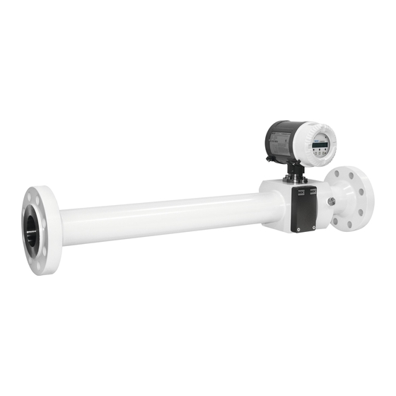
FLOWSIC600 DRU is an innovative ultrasonic dual-path gas meter for upstream applications based on FLOWSIC600. The meter has a full-bore design and includes a 10D inlet piping for piping diameters ≤ 4“. For larger diameters an additional specially for DRU manufactured 10D inlet piping is included in the scope of delivery.
-
Page 9: Application Range
Application range 2.1.2 Maximum volume flow rate Qmax is limited for gas pressures above 450 psig / 31 barg. The application range for different diameters of FLOWSIC600 DRU is shown in Fig. 2. Figure 2 Application range FLOWSIC600 · Addendum to Operating Instructions · 8017812/ZYM6/V 1-6/2018-05 · © SICK Engineering GmbH…
-
Page 10: Liquid Indication Diagnosis
The liquid indication diagnosis uses real-time monitoring of multiple diagnostic parameters of the FLOWSIC600 DRU in order to identify wet gas conditions (liquids in the gas stream such as liquid hydrocarbons, water and oil). Liquids in the gas stream are usually undesired in the gas production process and may require appropriate actions such as process optimization or consideration for meter readings.
-
Page 11: Installation
Make sure that the meter is mounted in the correct orientation ( Fig. 3).The flow direc- tion is marked on the meter body. FLOWSIC600 DRU must be installed as shown in Fig. 3 with upstream flow condi- tioner type CPA 55E. Installation without upstream flow conditioner or with another type of flow conditioner will cause higher uncertainty of measurement.
-
Page 12: Electrical Installation
FLOWSIC600 DRU Electrical Installation 2.3.2 The output configuration of FLOWSIC600 DRU can be taken from the instrument data- sheet in the manufacturer data record (MDR) and from the wiring diagram inside the rear housing cover. For instructions on the electrical installation please refer to OI FLOWSIC600, chapter 3.4.
-
Page 13: Technical Data
2 DO and 1 FO: 30 V, 10 mA Passive, galvanically isolated, open collector, fmax = 6 kHz (scalable) Interfaces RS-485 (2x, for configuration data output and diagnosis) FLOWSIC600 · Addendum to Operating Instructions · 8017812/ZYM6/V 1-6/2018-05 · © SICK Engineering GmbH…
-
Page 14
Weight 3 inch: 48 kg; 4 inch: 85 kg; 6 inch: 250 kg Electrical connection Voltage 12 … 28.8 V DC Power consumption ≤ 1 W FLOWSIC600 · Addendum to Operating Instructions · 8017812/ZYM6/V 1-6/2018-05 · © SICK Engineering GmbH… -
Page 15: Dimensional Drawings
All dimensions in mm (in). 3″ 1040 76,66 250.5 355.5 226.3 (40.94) (2.90) (9.86) (14.00) (8.27) (8.91) 4″ 1300 97.18 258.8 51.18 (3.83) (10.20) (15.60) (10.83) (10.19) FLOWSIC600 · Addendum to Operating Instructions · 8017812/ZYM6/V 1-6/2018-05 · © SICK Engineering GmbH…
-
Page 16: Flowsic600 Dru 6
FLOWSIC600 DRU FLOWSIC600 DRU 6″ 2.5.2 All dimensions in mm (in) 6″ 1950 146.4 355.6 (76.77) (5.76) (11.22) (18.20) (14.00) FLOWSIC600 · Addendum to Operating Instructions · 8017812/ZYM6/V 1-6/2018-05 · © SICK Engineering GmbH…
-
Page 17
FLOWSIC600 DRU FLOWSIC600 · Addendum to Operating Instructions · 8017812/ZYM6/V 1-6/2018-05 · © SICK Engineering GmbH… -
Page 18
E-Mail sales@sick.co.nz United Arab Emirates China Norway E-Mail sick@sick.no United Kingdom Denmark Poland E-Mail sick@sick.dk Finland Romania Vietnam France Russia Germany Singapore Hong Kong Slovakia E-Mail mail@sick-sk.sk Hungary Slovenia India South Africa www.sick.com SICK AG | Waldkirch | Germany | www.sick.com…
-
Page 1
O P E R A T I N G I N S T R U C T I O N S Applifoto 74 x 45 mm (150 dpi: 437 x 266 pixel) FLOWSIC600 Ultrasonic Gas Flow Meter x = 136 mm y = 58 mm Ultrasonic Gas Flow Meter… -
Page 2
Physikalisch Technische Bundesanstalt (~ Federal Metrology Office in Germany) Remote Terminal Unit Signal Processing Unit Verband der Elektrotechnik Elektronik Infor- mationstechnik (~ Association of German Electrical Engineers) FLOWSIC600 · Operating Instructions · 8010458 V 2.0 · © SICK MAIHAK GmbH… -
Page 3
Information about the use in potentially explosive atmospheres Important technical information for this product Important information on electric or electronic func- tions Supplementary information Link to information at another place FLOWSIC600 · Operating Instructions · 8010458 V 2.0 · © SICK MAIHAK GmbH… -
Page 4: Table Of Contents
Operating the FLOWSIC600 in safe areas ……..
-
Page 5
Connecting the FLOWSIC600 to a PC or Laptop……. . . -
Page 6
Sealing Plan …………. . . 94 FLOWSIC600 · Operating Instructions · 8010458 V 2.0 · © SICK MAIHAK GmbH… -
Page 7: Important Information
General Safety Instructions and Protective Measures Dangers Due to Hot, Corrosive and Explosive Gases and High Pressure Dangers Due to Heavy Loads Environmental Information and Instructions for Disposal FLOWSIC600 · Operating Instructions · 8010458 V 2.0 · © SICK MAIHAK GmbH…
-
Page 8: About This Document
About this Document 1. 1 This manual describes the FLOWSIC600 measuring system, which is used to determine the volumetric flow rate, volume and the speed of sound in gases transported in pipelines. It provides general information on the measuring method employed, design and function of the entire system and its components, and on planning, assembly, installation, calibration commissioning, maintenance and troubleshooting.
-
Page 9: Safety Instructions
Do not expose the equipment to mechanical stress, such as pigging. ● The flooding of the FLOWSIC600 with any liquid (e.g. for pressure or leakage tests) is an ● improper use. The consequences of such activities can not be foreseen or estimated.
-
Page 10: General Safety Instructions And Protective Measures
European Pressure Equipment Directive 97/23/EC. All relevant information for the particular application (as specified in the technical information questionnaire filled out by the customer) has been taken into account before commencing order processing. FLOWSIC600 · Operating Instructions · 8010458 V 2.0 · © SICK MAIHAK GmbH…
-
Page 11: Dangers Due To Heavy Loads
Only the printed-circuit boards must be disposed of as electronic scrap. FLOWSIC600 · Operating Instructions · 8010458 V 2.0 · © SICK MAIHAK GmbH…
-
Page 12
Important Information FLOWSIC600 · Operating Instructions · 8010458 V 2.0 · © SICK MAIHAK GmbH… -
Page 13: Product Description
Product Description FLOWSIC600 Product Description System Components Operating States and Signal Output MEPAFLOW600 CBM FLOWSIC600 · Operating Instructions · 8010458 V 2.0 · © SICK MAIHAK GmbH…
-
Page 14: System Components
Standard meter bodies are available in carbon steel, Low Temperature Carbon Steel and stainless steel. The meter bodies can be delivered in several nominal sizes (see → pg. 82, 7.1.3). FLOWSIC600 · Operating Instructions · 8010458 V 2.0 · © SICK MAIHAK GmbH…
-
Page 15: Ultrasonic Transducers
The electronics are mounted in the SPU enclosure certified to EN 60079-1 or IEC 60079-1 with protection type “d“ (flameproof enclosure). The transducer circuits are of an intrinsically safe design (category “ia“). FLOWSIC600 · Operating Instructions · 8010458 V 2.0 · © SICK MAIHAK GmbH…
-
Page 16: Operating Modes, Meter States And Signal Output
(transducer simulator). This function can only be activated if the system is in the “Configuration” mode. It is used to test a path-specific electronic module. Test cycles are automatically cancelled when leaving the “Configuration” mode. FLOWSIC600 · Operating Instructions · 8010458 V 2.0 · © SICK MAIHAK GmbH…
-
Page 17: Meter States
However, the SPU will cyclically try to re-establish valid measurements. As soon as the signal quality and number of valid measurements meet the required criteria, the SPU will automatically change back to the “Measurement valid” or “Check request” status. FLOWSIC600 · Operating Instructions · 8010458 V 2.0 · © SICK MAIHAK GmbH…
-
Page 18: Pulse Output And Status Information
Reg.#3034 “ErrorFreq“ (0-6 kHz). ** Default setting on delivery. *** Optional setting on customer request. The default setting for “Check request”, “Configuration” and “Measurement invalid” is “normally closed”. FLOWSIC600 · Operating Instructions · 8010458 V 2.0 · © SICK MAIHAK GmbH…
-
Page 19
Depending on the type of entry this will be: “I” for Information ● “W” for Warning ● “E” for Error ● After acknowledging all new entries, the flashing letter disappears. For details see → pg. 68, 5.4.1. FLOWSIC600 · Operating Instructions · 8010458 V 2.0 · © SICK MAIHAK GmbH… -
Page 20: Mepaflow600 Cbm
Installation A product CD containing the MEPAFLOW600 CBM software is included with the FLOWSIC600 when it is delivered. Insert the product CD into your CD-ROM drive to install the software. Start the file ‘FLOWSIC600_R_CD.exe‘ to install the software. Download from www.flowsic600.com MEPAFLOW600 CBM can be downloaded free of charge from the www.flowsic600.com…
-
Page 21: Overview
2.3.2 The MEPAFLOW600 CBM software supplies a menu-based user interface with many features for the diagnosis of the FLOWSIC600 system. It allows the access of all system parameters, displays diagnostic information in charts and graphs, generates reports (i.e. Maintenance reports) and data files (records, logs) which can be exported and can be used for data analysis.
-
Page 22
Product Description FLOWSIC600 · Operating Instructions · 8010458 V 2.0 · © SICK MAIHAK GmbH… -
Page 23: Installation
Installation FLOWSIC600 Installation General Notes Installation Mechanical Installation Electrical Installation FLOWSIC600 · Operating Instructions · 8010458 V 2.0 · © SICK MAIHAK GmbH…
-
Page 24: General Notes
Delivery 3.1.1 The FLOWSIC600 is delivered in a pre-assembled condition in a sturdy package. When unpacking the device, check for possible damage in transit. Pay particular attention to the interior of the meter body, any visible transducer components and the sealing surfaces on the flanges.
-
Page 25: Transport And Storage
Max. load information can be found on the type plate of the lifting gear. It is strongly recommended to use only the eye bolts when lifting the meter by itself. To lift the FLOWSIC600 please pay attention to Fig. 5.2.
-
Page 26: Installation
Measuring location 3.2.1 General requirements: The FLOWSIC600 can be installed in customary straight inlet and outlet pipes. The ● adjacent pipes must have the same nominal size as the meter body. The max. variation of the internal diameter of the inlet pipe from that of the meter body is 1%. Any welding beads and burs on the flanges of the inlet pipe shall be removed.
-
Page 27: Installation Configurations
1.5 .. 5 DN Configuration 1 ≥ 5 DN ≥ 3 DN min. 2 DN min. 2 DN 1.5 .. 5 DN Configuration 2 Flow conditioner Temperature measuring point FLOWSIC600 · Operating Instructions · 8010458 V 2.0 · © SICK MAIHAK GmbH…
-
Page 28
Two straight pipes shall be installed in the inlet and outlet sections if the meter is to be used bidirectionally. The temperature measuring point shall be disposed downstream the FLOWSIC600, seen in the direction of predominant use (position 1 or 2 in → Figure 7). Figure 7 FLOWSIC600 installation in the pipeline for bidirectional use ≥… -
Page 29: Mechanical Installation
Pressure Equipment Directive 97/23/EC. Installation staff must be familiar with the directives and standards ● applicable for pipeline construction. FLOWSIC600 · Operating Instructions · 8010458 V 2.0 · © SICK MAIHAK GmbH…
-
Page 30: Mounting The Flowsic600 In The Piping
An arrow on the meter body indicates the main direction of flow. It is recommended to install the FLOWSIC600 as indicated by this arrow if the meter is to be used for unidirectional flow applications. If the meter is to be used in the bidirectional mode, the arrow indicates the positive direction of flow.
-
Page 31: Spu Alignment
Loosen the hexagon Position the SPUTighten the hexagon socket head screw socket head screw NOTICE: Do not forget to tighten the hexagon socket head screw after positioning the SPU. FLOWSIC600 · Operating Instructions · 8010458 V 2.0 · © SICK MAIHAK GmbH…
-
Page 32: Electrical Installation
Pre-requisites Wiring work (routing and connecting the power supply and signal cables), which is necessary when installing the FLOWSIC600, is not included in the scope of delivery. The mechanical installation described in Section → 3.3 must be completed first. Comply with the minimum cable specification requirements set out in Section → 3.4.2.
-
Page 33
Service PC / higher- (Ex i isolating transformer only level control system required for intrinsically safe 12 … 24 V DC installation) Safe area Hazardous area FLOWSIC600 FLOWSIC600 · Operating Instructions · 8010458 V 2.0 · © SICK MAIHAK GmbH… -
Page 34: Cable Specifications
1000 m at 0,75 mm² (1500 ft for 20 pairs and prevent them from AWG) accidental short-circuit. Cable diameter 6 … 12 mm (1/4 to 1/2 inch) Fixing range of the cable glands FLOWSIC600 · Operating Instructions · 8010458 V 2.0 · © SICK MAIHAK GmbH…
-
Page 35: Checking The Cable Loops
Incorrect cabling may cause failure of the FLOWSIC600. This will invalidate ● warranty claims. The manufacturer assumes no liability for consequential damage. FLOWSIC600 · Operating Instructions · 8010458 V 2.0 · © SICK MAIHAK GmbH…
-
Page 36: Terminal Enclosure On The Spu
4 x 2 x 0.5 mm core cable (Li2YCY [TP] or equivalent) 10-pole terminal block MODBUS for signal inputs and outputs 4 x 2 x 0.5 mm (Li2YCY [TP] or equivalent) FLOWSIC600 · Operating Instructions · 8010458 V 2.0 · © SICK MAIHAK GmbH…
-
Page 37
Terminal assignment for use in safe areas Terminals 2 and PE are bridged internally, i.e. there is no insulation between PE and negative potential (see → Figure 11). FLOWSIC600 · Operating Instructions · 8010458 V 2.0 · © SICK MAIHAK GmbH… -
Page 38: Operating The Flowsic600 In Safe Areas
“Direction of flow” (default) (alternative “Warning”) Alternative assignment with second 9600 Baud, 8 data bits, no parity, 1 stop bit Baud rate to be set serial port (RS485) through software FLOWSIC600 · Operating Instructions · 8010458 V 2.0 · © SICK MAIHAK GmbH…
-
Page 39: Operation In Hazardous Areas (Directive 94/9/Ec (Atex)
The power supply and field connections are designed with the increased type of protection (“e“). The transducer connections are of an intrinsically safe design (“ia“). All screw-type terminals as well as air gaps and creepage distances of the FLOWSIC600 comply with EN 60079-7.
-
Page 40
After deinstallation and before every reinstallation the sealings must be renewed according to the original assembly. Sealings can be ordered from SICK (provide article number and serial number from type plate). -
Page 41
Aux. power Power supply Signal processing unit Digital output (SPU) RS485 Pressure-resistant Digital output space “d” Field connections Digital output Digital output Meter body Ultrasonic transducers “ia” FLOWSIC600 · Operating Instructions · 8010458 V 2.0 · © SICK MAIHAK GmbH… -
Page 42
= ±59 mA only) = 1399 mW = 556 mW = 556 mW Internal capacity: negligible negligible negligible Internal inductance: = 20.6 mH = 15.5 mH = 6.7 mH FLOWSIC600 · Operating Instructions · 8010458 V 2.0 · © SICK MAIHAK GmbH… -
Page 43: Commissioning
General Notes Connecting the FLOWSIC600 to a PC or Laptop Connecting to the FLOWSIC600 with MEPAFLOW600 CBM Identification Field Setup Function Test Activation of Path Compensation Sealing FLOWSIC600 · Operating Instructions · 8010458 V 2.0 · © SICK MAIHAK GmbH…
-
Page 44: General Notes
Parameter write lock has to be agreed to by the applicable national authorities. In all other cases the output parameters of the FLOWSIC600 can be adapted on site by trained staff. Commissioning the FLOWSIC600 involves the following steps, no matter whether the device is installed at a test facility or at the final measuring location: Connecting the FLOWSIC600 to a PC or Laptop (→ pg. 45, 4.2)
-
Page 45: Connecting The Flowsic600 To A Pc Or Laptop
Connecting the FLOWSIC600 via RS485 / RS232 cable 4.2.1 Interface sets for the connection of the FLOWSIC600 with a PC via serial- or USB-interface can be ordered from SICK. See → pg. 46, Table 3. The FLOWSIC600 serial interface conforms with the RS485 standard. An RS485 /RS232 cable and a 1:1 interface cable (pin 2 –…
-
Page 46: Connecting The Flowsic600 Via Rs485/Usb Converter
USB converter is necessary to transform the signal for the RS485 device interface. The USB converter available through SICK contains a CD-ROM with a software driver which must be installed before an online connection between the FLOWSIC600 and the MEPAFLOW600 CBM software can be established.
-
Page 47: Connecting To The Flowsic600 With Mepaflow600 Cbm
4.3.1 The MEPAFLOW600 CBM software is provided on the product CD shipped with the meter. It can also be downloaded from www.flowsic600.com. See → pg. 20, 2.3.1 for more details on the installation. After successful installation, start the MEPAFLOW600 CBM by selecting the “MEPAFLOW600 CBM”…
-
Page 48: Choosing An User Access Level
Create a new meter entry in the meter database by clicking the “New” button. Then follow the instructions on screen. FLOWSIC600 · Operating Instructions · 8010458 V 2.0 · © SICK MAIHAK GmbH…
-
Page 49: Online Connection: Direct Serial
COM port which has to be individually configured. After the connection has been established, MEPAFLOW600 CBM displays the start page (can be specified in the Program settings) and the current readings from the meter. FLOWSIC600 · Operating Instructions · 8010458 V 2.0 · © SICK MAIHAK GmbH…
-
Page 50: Online Connection: Ethernet
Commissioning Online Connection: Ethernet 4.3.5 The FLOWSIC600 can be connected to a network via Ethernet with an according adapter. This adapter translates the meter MODBUS communication (ASCII or RTU) to MODBUS TCP. MEPAFLOW600 CBM supports the MODBUS TCP protocol. Requirements The Ethernet connection requires firmware V3.3.05 or higher installed on…
-
Page 51
“MODBUS TCP to MODBUS ASCII/RTU Converter“, Model MES1b by B&B Electronics. This adapter is shipped with a software, which searches the network for connectable devices and supplies the user with the according IP addresses. FLOWSIC600 · Operating Instructions · 8010458 V 2.0 · © SICK MAIHAK GmbH… -
Page 52: Identification
NOTICE: Type Approval If the FLOWSIC600 is used for fiscal metering, the approved firmware versions and the associated check sums are documented in the national pattern approval certificates. FLOWSIC600 · Operating Instructions · 8010458 V 2.0 · © SICK MAIHAK GmbH…
-
Page 53: Field Setup
NAMUR (8,2V / 0,8…6,6mA) Painting Grey white (RAL9002)/grey (RAL7012) sta Switching state normally open Pressure tapping 1/4″ NPTF DO3 Clamp 81/82(RS485) SICK_MODBUS_ASCII TRANSDUCER Transcucer material (wetted) Titanium FLOWSIC600 · Operating Instructions · 8010458 V 2.0 · © SICK MAIHAK GmbH…
-
Page 54: Disconnecting From The Meter And Closing The Session
Click the “Disconnect“ button. The “Session description“ window opens. Describe the activies you carried out during the session (e.g. “Field Setup“). Click the “OK“ button. FLOWSIC600 · Operating Instructions · 8010458 V 2.0 · © SICK MAIHAK GmbH…
-
Page 55: Function Test
30 seconds after the power supply is switched on. If the yellow LED flashes, the FLOWSIC600 works in the operation state ’’Check request’’ with an insignificantly reduced accuracy (e.g. if one path fails). If the yellow LED lights up permanently, the measurement is invalid. In this case, you must diagnose the error (see Chapter 8 of this Manual).
-
Page 56: Function Test With Mepaflow600 Cbm
Figure 22 “Path Diagnosis” wizard in MEPAFLOW600 CBM Main system FLOWSIC600 · Operating Instructions · 8010458 V 2.0 · © SICK MAIHAK GmbH…
-
Page 57
Figure 25). If a lamp for “Time plausibility” is on, it indicates an incorrect zero phase. Figure 23 Signal window displaying ultrasonic signal in the “Path Diagnosis” page FLOWSIC600 · Operating Instructions · 8010458 V 2.0 · © SICK MAIHAK GmbH… -
Page 58
Commissioning Go to the “Meter values” page to check that the measured SOS values are almost the same at all paths of the FLOWSIC600, and that they differ by less then 0.1% (→ Figure 24). Switch between display of absolute and difference SOS by clicking the right mouse button on the SOS graph and using the context-menu. -
Page 59: Activation Of Path Compensation
Activation of Path Compensation 4 . 7 If the status bit “Path compensation valid” is “active”, then the FLOWSIC600 is able to compensate a path failure. The meter automatically sets this bit to “active” after operating for about 20 minutes with error free measurement at all paths at a gas velocity between 1 to 8m/s (3 to 25ft/s) and also about 20 minutes at a gas velocity higher than 8m/s (25ft/s).
-
Page 60: Sealing
Commissioning Sealing 4. 8 After having completed the commissioning, seal the signal processing unit (if required) in accordance with the sealing plan (see Section → pg. 94, 7.5). FLOWSIC600 · Operating Instructions · 8010458 V 2.0 · © SICK MAIHAK GmbH…
-
Page 61: Maintenance
Maintenance FLOWSIC600 Maintenance General Routine Checks Maintenance Report Optional Data Download FLOWSIC600 · Operating Instructions · 8010458 V 2.0 · © SICK MAIHAK GmbH…
-
Page 62: General
→ »Comparing theoretical and measured Speed of Sound (SOS)« (pg. 63) → »Checking the Meter Health« (pg. 64) → »Time Synchronization« (pg. 65) → »Battery Lifetime / Capacity« (pg. 66) Documentation: → »Maintenance Report« (pg. 67) FLOWSIC600 · Operating Instructions · 8010458 V 2.0 · © SICK MAIHAK GmbH…
-
Page 63: Routine Checks
Routine Checks 5 . 2 The information displayed on the front panel LCD display of the FLOWSIC600 meter can be checked to ensure that the system is functioning properly. The MEPAFLOW600 CBM software provides a more user friendly way for doing routine checks.
-
Page 64: Checking The Meter Health
Checking the Meter Health 5.2.2 The FLOWSIC600 monitors its own meter health with User Warnings and system alarms. If the outputs are configured to indicate alarms and / or User Warnings, it is not necessary to manually check the meter health.
-
Page 65: Time Synchronization
Synchronization via MODBUS The date and the time of the FLOWSIC600 can be set separately by an external write. Each operation for date and time causes a separate entry in the Custody logbook [1]. Alternatively the synchronization function can be used. To use this method, the date register (#5007) and the time register (#5008) have to be written sequentially within 2 seconds.
-
Page 66: Battery Lifetime / Capacity
Battery Lifetime / Capacity 5.2.4 The Real Time Clock (RTC) of the FLOWSIC600 is buffered by a battery with a guaranteed life span of 10 years. The remaining battery capacity can be viewed on the LCD in the first menu level (see Technical Information).
-
Page 67: Maintenance Report
“Meter explorer” and the “Report manager”. The Maintenance report can also be exported to Excel using the direct link provided when the Maintenance report is displayed. FLOWSIC600 · Operating Instructions · 8010458 V 2.0 · © SICK MAIHAK GmbH…
-
Page 68: Optional Data Download
The logbook entries are now downloaded to your MEPAFLOW600 CBM database. You can view them offline without connection to the meter or share them with others (export the device or the session). FLOWSIC600 · Operating Instructions · 8010458 V 2.0 · © SICK MAIHAK GmbH…
-
Page 69
If the Parameter write lock was unlocked prior to clearing the meter logbook, follow all necessary procedures to bring the meter to back to its original state. FLOWSIC600 · Operating Instructions · 8010458 V 2.0 · © SICK MAIHAK GmbH… -
Page 70
Maintenance FLOWSIC600 · Operating Instructions · 8010458 V 2.0 · © SICK MAIHAK GmbH… -
Page 71: Troubleshooting
Troubleshooting FLOWSIC600 Troubleshooting General Troubleshooting Indication of Meter States, System Alarms and Warnings Generation of Diagnosis Session Meter Connection Troubleshooting FLOWSIC600 · Operating Instructions · 8010458 V 2.0 · © SICK MAIHAK GmbH…
-
Page 72: General Troubleshooting
If the cause of the problem cannot be localized, it is recommended to use the MEPAFLOW600 CBM software to record the current parameter set and diagnosis values in a diagnosis session file (→ pg. 77, 6.3) and send this to a local SICK representative. General Troubleshooting 6.
-
Page 73: Checking The Meter Status» Window
Contact trained staff or your SICK representative. force the user to change Trained staff: Change the battery according to the procedure described in the the battery. Service Manual FLOWSIC600 · Operating Instructions · 8010458 V 2.0 · © SICK MAIHAK GmbH…
-
Page 74
Main system bar with “System” button and opened “Meter Status” window Opens the “Meter Status” window Main system General “Meter Status” section Indication if logbook(s) contains unacknowledged entries “Logbooks“ Battery Lifespan section “DataLogs“ section FLOWSIC600 · Operating Instructions · 8010458 V 2.0 · © SICK MAIHAK GmbH… -
Page 75: Checking The User Warnings
Check the window for yellow lights and proceed according to the “Technical Information“.. Figure 33 Main system bar with button “User” and opened “User Warnings” window Opens the “User Warnings” window FLOWSIC600 · Operating Instructions · 8010458 V 2.0 · © SICK MAIHAK GmbH…
-
Page 76: Battery Lifetime / Capacity
Battery Lifetime / Capacity 6.2.3 Because the FLOWSIC600 has no regular maintenance cycle, after 8.5 years, a message will be generated automatically, which forces the operator to change the battery (→ Figure 34 and → Figure 35). The procedure to change the battery is decribed in the Service Manual.
-
Page 77: Generation Of A Diagnosis Session
Diagnosis session with all relevant data. The entire process usually takes about three minutes. If the logbooks contain a lot of entries, the process may take longer. Email the Diagnosis session file to your SICK representative for support. FLOWSIC600 · Operating Instructions · 8010458 V 2.0 · © SICK MAIHAK GmbH…
-
Page 78: Meter Connection Troubleshooting
Use the options in the displayed window to make MEPAFLOW600 CBM search with wider options (see → Figure 37), especially If parameters (e.g. the baudrate) may have changed. FLOWSIC600 · Operating Instructions · 8010458 V 2.0 · © SICK MAIHAK GmbH…
-
Page 79: Appendix
Appendix FLOWSIC600 Appendix Conformities and Technical Data Logbooks Sealing Plan FLOWSIC600 · Operating Instructions · 8010458 V 2.0 · © SICK MAIHAK GmbH…
-
Page 80: Conformities And Technical Data
PED and ASME B31.5 “Process piping”. The FLOWSIC600 meets or exceeds the new proposed audit logging requirements of API 21.1 (draft). Specifically the API 21.1 (draft) requires the ultrasonic meter to provide an internal record of any configuration change, including the original and new parameter, and date and time the change occurred.
-
Page 81
HART-Protocol (By selection of hardware variant 2 and 8 only) Front panel LED SICK LCD SICK Custody Transfer design Rev. 1.8 ** The Instrument Data Sheet is included in the Manufacturer Data Report (MDR). FLOWSIC600 · Operating Instructions · 8010458 V 2.0 · © SICK MAIHAK GmbH… -
Page 82: Technical Data
(NPS 48) 1,600 100,000 56,500 3,531,000 *When a configuration with flow conditioner is used, the velocity of gas must not exceed 40 m/s (131 ft/s) in the pipe. FLOWSIC600 · Operating Instructions · 8010458 V 2.0 · © SICK MAIHAK GmbH…
-
Page 83
(-20 °C ≤ T ≤ +60 °C; 0.8 bar(a) ≤ p ≤ 1.1 bar(a))(-4 °F ≤ T ≤ 140°F; 11.6 psi(a) ≤ p ≤ 16 psi(a)) medium medium medium medium FLOWSIC600 · Operating Instructions · 8010458 V 2.0 · © SICK MAIHAK GmbH… -
Page 84
DN 400 G2500 4000 1800 (16“) G4000 6500 1110 G6500 10000 G6500 E 12000 DN 450 G2500 4000 1800 (18“) G4000 6500 1110 G6500 10000 G6500 E 12000 FLOWSIC600 · Operating Instructions · 8010458 V 2.0 · © SICK MAIHAK GmbH… -
Page 85
— for a flow range of 1:20 Qt=0.20 Q — for a flow range of 1:30 Qt=0.15 Q ≥ — for a flow range of 1:50 Qt=0.10 Q FLOWSIC600 · Operating Instructions · 8010458 V 2.0 · © SICK MAIHAK GmbH… -
Page 86: Logbooks
3007 Failure during storage of path compensation Storage error parameter E-PathComp. 0001 Storage error E+System 0001 3008 Meter clock time invalid ClockTime inval. E-System 0001 ClockTime inval. FLOWSIC600 · Operating Instructions · 8010458 V 2.0 · © SICK MAIHAK GmbH…
-
Page 87
EVC module error W-EVC 0001 EVC module error I Power ON 0001 1001 Flow meter power ON dd/mm/yy mm:ss I Set Time 0001 1002 Meter clock adjusted dd/mm/yy mm:ss FLOWSIC600 · Operating Instructions · 8010458 V 2.0 · © SICK MAIHAK GmbH… -
Page 88
DataLog 3 cleared Reset I+DataLog 1 0001 1021 DataLog 1 overflow Overflow I-DataLog 1 0001 Overflow I+DataLog 2 0001 1022 DataLog 2 overflow Overflow I-DataLog 2 0001 Overflow FLOWSIC600 · Operating Instructions · 8010458 V 2.0 · © SICK MAIHAK GmbH… -
Page 89
I Logbook 3 0001 1009 Parameter logbook [3] erased and initialized Reset and Init I+Logbook 3 0001 1011 Parameter logbook [3] overflow Overflow I-Logbook 3 0001 Overflow FLOWSIC600 · Operating Instructions · 8010458 V 2.0 · © SICK MAIHAK GmbH… -
Page 90: Connection Diagrams For Operating The Flowsic 600 In Hazardous Areas In Accordance With North American Guidelines (Csa)
Connection Diagrams for Operating the FLOWSIC 600 in Hazardous 7. 3 Areas in Accordance with North American Guidelines (CSA) Figure 39 Control drawing CSA 781.00.02 (page 1) FLOWSIC600 · Operating Instructions · 8010458 V 2.0 · © SICK MAIHAK GmbH…
-
Page 91
Appendix Figure 40 Control drawing CSA 781.00.02 (page 2) FLOWSIC600 · Operating Instructions · 8010458 V 2.0 · © SICK MAIHAK GmbH… -
Page 92: Wiring Examples
Appendix Wiring Examples 7. 4 Intrinsically safe installation 7.4.1 Figure 41 FLOWSIC600 intrinsically safe installation FLOWSIC600 · Operating Instructions · 8010458 V 2.0 · © SICK MAIHAK GmbH…
-
Page 93: Non-Intrinsically Safe Installation
Appendix Non-intrinsically safe installation 7.4.2 Figure 42 FLOWSIC600 non-intrinsically safe installation FLOWSIC600 · Operating Instructions · 8010458 V 2.0 · © SICK MAIHAK GmbH…
-
Page 94: Sealing Plan
Appendix Sealing Plan 7. 5 Figure 43 Sealing plan, part 1 FLOWSIC600 · Operating Instructions · 8010458 V 2.0 · © SICK MAIHAK GmbH…
-
Page 95
Appendix Figure 44 Sealing plan, part 2 FLOWSIC600 · Operating Instructions · 8010458 V 2.0 · © SICK MAIHAK GmbH… -
Page 96
Appendix Figure 45 Sealing plan, part 3 FLOWSIC600 · Operating Instructions · 8010458 V 2.0 · © SICK MAIHAK GmbH… -
Page 97
Appendix Figure 46 Sealing plan, part 4 alternatively FLOWSIC600 · Operating Instructions · 8010458 V 2.0 · © SICK MAIHAK GmbH… -
Page 98
Appendix Figure 47 Examples: Main type plates at the signal processing unit Figure 48 Example: Type plate at the meter body FLOWSIC600 · Operating Instructions · 8010458 V 2.0 · © SICK MAIHAK GmbH… -
Page 99
Appendix FLOWSIC600 · Operating Instructions · 8010458 V 2.0 · © SICK MAIHAK GmbH… -
Page 100
You will find our local subsidiary or agency at: www.sick.com Your local sales and service partner SICK MAIHAK GmbH | Germany Nimburger Str. 11 | 79276 Reute | www.sick.com Phone +49 7641 469-0 | Fax +49 7641 469-11 49 | info.pa@sick.de…
-
Trimble GL622N
GL400 Serieswww.trimble.comTrimble Construction Division5475 Kellenburger RoadDayton, Ohio 45424USA+1-937-245-5600 Phonewww.trimble.com User GuideBedienungsanleitungManuel de l´utilisateurGuida per l´usoGúia del usuarioGebruikershandleidingOperatörshandbokBrugermanualGuia do UsuárioBruksanvisningKäyttäjän opas� …
GL622N Measuring Instruments, 22
-
Laserworld RTI PIKO Series
Manual / Bedienungsanleitung /Mode d´emploiRTI PIKO SeriesPlease spend a few minutes to read this manual fullybefore operating this laser!Bitte lesen Sie diese Bedienungsanleitung sorgfältig vor Inbetriebnahme dieses Showlasersystems!Avant d’utiliser cet appareil pour la première fois nous vous recommandonsde lire …
RTI PIKO Series Kitchen Appliances, 57
-
Bosch GLM 7000
Robert Bosch GmbHPower Tools Division70745 Leinfelden-EchterdingenGermanywww.bosch-pt.com2 609 141 034 (2013.03) O / 46 ASIA GLM 7000 Professionalen Original instructionscn 正本使用说明书tw 原始使用說明書ko 原始使用說明書th หนังสือคู่มือการใช้งานฉบ� …
GLM 7000 Measuring Instruments, 45
-
Bosch GLL 150 E
IMPORTANT: IMPORTANT : IMPORTANTE: Read Before Using Lire avant usage Leer antes de usarOperating/Safety InstructionsConsignes de fonctionnement/sécuritéInstrucciones de funcionamiento y seguridad For English Version Version française Versión en español See page 6 Voir page 17 Ver la página 311-877-BOS …
GLL 150 E Measuring Instruments, 44
-
Falcon G350 series
Falcon G350/G450 Series Exerciser/Analyzer Quick Start Guide Contents What’s in the box ………………………………………………………………………………………………………………………… 1 How to set up your system ……………………………………………………. …
G350 series Measuring Instruments, 5
-
Landis & Gyr Ultrasonic UH50
UH50 Ultrasound Heat Meter Subject to change without prior notice UH 106-101c Page 1 / 13 Heat Meter Ultrasonic® UH50Configuration Instructions UH 106-101c Version: June 2007Safety information: ) Do not pick up by the electronic unit ) Be careful of sharp edges (thread, flange, measuring tube) ) Installation an …
Ultrasonic UH50 Measuring Instruments, 13