-
Contents
-
Table of Contents
-
Troubleshooting
-
Bookmarks
Quick Links
Form Number A6115
Part Number D301150X412
January 2007
™
FloBoss
S600 Flow Manager
Instruction Manual
Remote Automation Solutions
Related Manuals for Emerson FloBoss S600
Summary of Contents for Emerson FloBoss S600
-
Page 1
Form Number A6115 Part Number D301150X412 January 2007 ™ FloBoss S600 Flow Manager Instruction Manual Remote Automation Solutions… -
Page 2: January 2007
ROCLINK is a trademark of one of the Emerson Process Management companies. The Emerson logo is a trademark and service mark of Emerson Electric Co. All other marks are the property of their respective owners. © 2001-2007 Remote Automation Solutions, division of Emerson Process Management. All rights reserved.
-
Page 3: Table Of Contents
Contents Chapter 1 – General Information Scope of Manual…………………..1-1 FloBoss S600 Flow Manager ……………….1-2 Config600 Configuration Software ……………….1-5 1.3.1 Config600 Lite ………………..1-5 1.3.2 Config600 Lite+ ………………..1-5 1.3.3 Config600 Pro ………………..1-6 Related Specification Sheets………………..1-6 Chapter 2 – Installation Preparing for Installation………………..2-1 Environmental Considerations………………2-2…
-
Page 4: Startup
4.2.3 Turbine Pulse Inputs ………………4-21 4.2.4 Pulse Outputs (PULSEOUT) …………….4-22 4.2.5 Frequency Inputs………………..4-22 4.2.6 P154 Prover Bit Links (Jumpers) …………..4-24 P188 HART Board………………….4-25 Chapter 5 – Front Panel Description……………………5-1 Front Panel Port……………………5-2 Keypad……………………..5-2 5.3.1 F Keys ……………………5-2 5.3.2 Direction and Menu Keys ……………….5-3 5.3.3 Numeric Keys …………………5-3 5.3.4…
-
Page 5: Front Panel
8.3.6 Upgrading the BIOS ……………….8-8 Appendix A – Glossary Appendix B – Front Panel Navigation Main Menu ……………………B-1 Flow Rates Menu………………….B-2 Totals Menu ……………………B-2 Operator Menu……………………. B-3 Plant I/O Menu……………………. B-4 System Settings Menu………………… B-4 Tech/Engineer Menu ………………….. B-5 Calculations Menu ………………….
-
Page 6
Revised Jan-07… -
Page 7: Chapter 1 — General Information
This chapter details the structure of this manual and provides an overview of the S600 and its components. In This Chapter Scope of Manual…………….. 1-1 FloBoss S600 Flow Manager …………. 1-2 Config600 Configuration Software…………1-5 1.3.1 Config600 Lite……………. 1-5 1.3.2 Config600 Lite+ …………..
-
Page 8: Floboss S600 Flow Manager
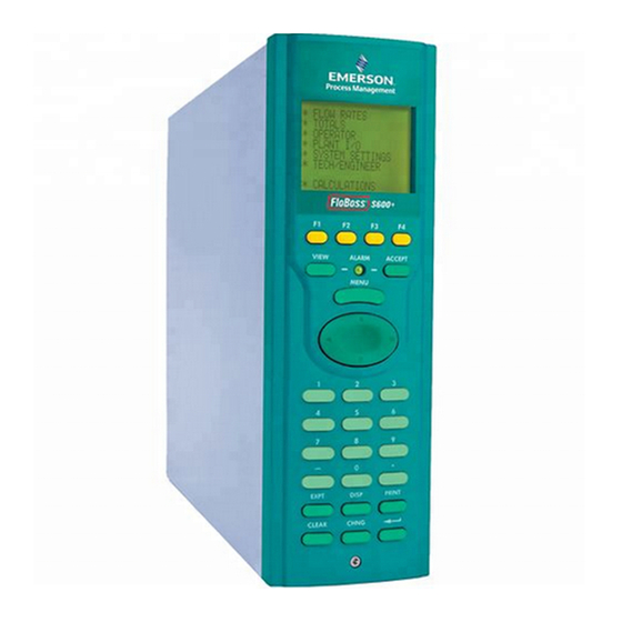
FloBoss S600 Flow Manager Figure 1-1. The FloBoss S600 Flow Manager The FloBoss S600 Flow Manager is a panel-mount flow computer designed specifically to measure hydrocarbon liquid and gas where versatility and accuracy matter. The S600’s standard features make it ideal for fiscal measurement, custody transfer, batch loading, and meter proving applications.
-
Page 9: Cpu Board
S600 Instruction Manual protection with a detailed event log for audit purposes (supports ® ® Windows Internet Explorer Version 6 or greater). Two configurable EIA-232 (RS-232) serial ports. Three EIA-422/485 (RS-422/RS-485) serial ports (up to 38400 bps baud) for connection to intelligent meters, Modbus SCADA data networks, DCS Supervisory Systems, and so on.
-
Page 10
S600 Instruction Manual Figure 1-3. Intelligent I/O Board You can manage a configuration through the front panel interface or create a configuration through configuration software (Config600) running on a personal computer (PC). The front panel interface consists of a backlit LCD display, a 29-button keypad, and an alarm status LED. -
Page 11: Config600 Configuration Software
S600 Instruction Manual Config600 Configuration Software The Config600 configuration software is a suite of editors that enable you to monitor, configure, and calibrate the S600. The software has three versions: Config600 Lite, Config600 Lite+, and Config600 Pro. : The S600 will not operate until you send a configuration to it Note from the host PC.
-
Page 12: Config600 Pro
S600 Instruction Manual With Config600 Lite+ you can: Create a new application from base templates for gas, liquid, and prover applications. Edit initialization process data, including orifice size, analog input scaling, alarm limits, and keypad values. Build and customize Modbus slave maps, Modbus master polling sequences, front panel displays, and period report formats.
-
Page 13: Chapter 2 — Installation
S600 Instruction Manual Chapter 2 – Installation This chapter provides instructions on installing the FloBoss S600, including installation preparation, procedures for mounting the panels, and the installation and removal of plug-in boards. In This Chapter Preparing for Installation…………..2-1 Environmental Considerations…………2-2 Required Tools for Installation…………
-
Page 14: Environmental Considerations
S600 Instruction Manual Figure 2-1. FloBoss S600 System Components Environmental Considerations The S600 panel mount is designed for use within the control room. Place it in a position that provides ease of use, comfort, and safety for operators and maintenance personnel. The optimum height for viewing and using the display and keypad is at operator eye level.
-
Page 15: Installing The S600
S600 Instruction Manual Installing the S600 Refer to the following procedures for installing the various S600 components, including the front panel, panel-mounted unit, and plug-in board. 2.4.1 Unpacking the S600 Unpack the S600 carefully and inspect parts for visual damage. : Do not discard packaging material until after you have identified Note all pieces of the shipment and you are confident that all parts are…
-
Page 16
S600 Instruction Manual Figure 2-3. Lifted Front Panel Disconnect the ribbon cable from the back of the front panel at the blue connector (refer to Figure 2-4). Observe the orientation of the connector with its mating keyway. You must correctly re-insert the ribbon cable at the end of the installation process. -
Page 17: Installing The Panel-Mounted Unit
S600 Instruction Manual Table 2-1. Mounting Dimensions Part Dimensions Display Keypad Molding 85 mm (3.35″) width x 269 mm (10.59″) height x 28 mm (1.10″) deep Case 84.5 mm (3.327″) width x 270 mm (10.63″) height x 303.8 mm (11.94″) deep Panel Cutout 66 mm (2.6″) width x 150 mm (5.9″) height…
-
Page 18
S600 Instruction Manual Figure 2-6. Panel Cutout Dimensions : The S600 fits into existing S500, 869 flow computer panel Note cutouts. Ensure a panel thickness of at least 3 mm (0.12 in) to prevent distortion. If you use a thinner panel, support the rear of the case (refer to Figure 2-7). -
Page 19: Reinstalling The Front Panel
S600 Instruction Manual Place the front of the case against the rear of the prepared cutout. Re-install the top and bottom bosses and tighten with a 5.5 mm (5 BA) hex wrench. Once you have fitted the rear support, use a self-tapping screw to secure the case to the rear support.
-
Page 20
S600 Instruction Manual Ejectors Figure 2-8. Unscrewing the Retention Screws Unlatch the ejectors for the appropriate board and pull the board clear of the case. You may need to rock the board slightly to release the connectors (refer to Figures 2-9 and 2-10). Figure 2-9. -
Page 21: Board Ready For Removal Or Insertion
S600 Instruction Manual Figure 2-10. Board Ready for Removal or Insertion To install a plug-in board: Carefully align the boards with the guides (located at the top and bottom of the case). Gently slide the board into the case until it mates fully with the appropriate connector on the backplane.
-
Page 22
S600 Instruction Manual 2-10 Installation Revised Jan-07… -
Page 23: Chapter 3 — Cpu
S600 Instruction Manual Chapter 3 – CPU This chapter provides information on plug-in connector blocks and bit link (jumper) settings for the P152 CPU board. In This Chapter P152 CPU Board …………….3-1 Power Supply………………3-3 3.2.1 Watchdog Relay …………..3-4 3.2.2 On-Board Battery Backup…………
-
Page 24: P152 Cpu Board
S600 Instruction Manual TB-1 Power COM 4 COM 3 COM 1-2 Remote I/O TB-2 COM 5, 6, 7 RS-232/RS-485 Network Figure 3-1. P152 CPU Backplate Figure 3-2. P152 CPU Board Revised Jan-07…
-
Page 25: Power Supply
S600 Instruction Manual P152 CPU NETWORK SERVICE SERVICE RJ45 TB — 1 + VE 24V DC SUPPLY + 24v ETHERNET + 15v COMPUTER ALARM COMM — 4 SERVICE RJ45 SIG GND REMOTE I/O SERVICE ‘9’ D FEMALE TX + RESET RS232 10.SEL(1) RS485…
-
Page 26: Watchdog Relay
S600 Instruction Manual The startup in-rush current may draw 6 Amps for approximately 100 milliseconds. This in-rush becomes significant when multiple flow computers are connected to the same power supply. An on-board anti-surge fuse (2.5 Amp rating) protects the supply line should a fault occur within the unit.
-
Page 27: Communication Ports
S600 Instruction Manual Table 3-3. Battery Specifications Charging Time (20%-80%) 48 hours Hold-up Time (without recharge) 3 months at 20° C (68° F), 1 month at 40° C (104° F) Battery Life (Typical) 5-7 years Battery Backup Holdup Time (after battery has failed its 2 weeks at 20°…
-
Page 28: Rs-422)/Eia-485 (Rs-485) Multi-Drop Port
S600 Instruction Manual Table 3-5. COM3 and COM4 Pin Connections Function Figure 3-4. Pin Connections The maximum cable length is a function of the baud rate and quality of cable used. For example, a maximum length of 15 m (50 ft) should be used at 19200 bps when using unscreened cable.
-
Page 29: Ethernet Lan Port
S600 Instruction Manual Table 3-6. COM5, COM6, and COM7 Pin Connections Channel Function COM5 COM6 COM7 Signal Common 3.3.3 Ethernet LAN Port The standard Ethernet port on the CPU card’s backplate is for high- speed communications using an Ethernet Local Area Network (LAN) architecture.
-
Page 30: Link Cable
S600 Instruction Manual Table 3-7. COM1-2 Pin Connections Function TX to R. Display SPEAKER OUT TX to PC RTS to PC RX from R. Display CTS to R. Display RX from PC CTS to PC A special serial cable is required to connect the host PC to the FloBoss Connecting to the S600 unit.
-
Page 31: Cpu On-Board Connectors
S600 Instruction Manual CPU On-Board Connectors Table 3-8 shows the miscellaneous device connectors provided on the P152 CPU module. This information is for identification purposes only. Do not modify these connections unless told to do so by the factory. Table 3-8. Miscellaneous Device Connectors for the P152 CPU Module Socket Description DIN Backplane Connector…
-
Page 32: Dual Ethernet Lan Port
S600 Instruction Manual Jumper (Link) Position Description Flash LK15 1-2/2-3 Block 0 — 1M — Write Prohibited (1-2) or Write Enabled (2-3) LK16 1-2/2-3 Block 1 — 2M — Write Prohibited (1-2) or Write Enabled (2-3) LK17 1-2/2-3 Block 2 — 3M — Write Prohibited (1-2) or Write Enabled (2-3) LK18 1-2/2-3…
-
Page 33
S600 Instruction Manual Figure 3-6. Dual Ethernet Communications Card The second Ethernet port is usually shipped from the factory pre- installed. If pre-installed, no hardware configuration or wiring is required. For field installation, the second Ethernet board is provided with a specialized backplate. -
Page 34
S600 Instruction Manual 3-12 Revised Jan-07… -
Page 35: Chapter 4 — Input/Output (I/O)
S600 Instruction Manual Chapter 4 – Input/Output (I/O) This chapter provides information on plug-in connector blocks and field wiring (ANIN, PRT, and DPR signals). In This Chapter P144 I/O Board ………………. 4-1 4.1.1 Analogue Inputs (ANIN)…………4-3 4.1.2 Analogue Outputs (DAC)…………4-5 4.1.3 Digital Inputs (DIGIN)………….
-
Page 36: Digout
S600 Instruction Manual SKT-A ANIN 1-10 ANOUT 1-4 SKT-B ANIN 11-12 DIGIN 1-6 DIGOUT 1-2 Freq Inputs Pulse Outputs SKT-C DIGIN 7-16 DIGOUT 3-12 Turbine Inputs Figure 4-1. Backplate with P144 I/O Board Figure 4-2. P144 I/O Board Revised Jan-07…
-
Page 37: Analogue Inputs (Anin)
S600 Instruction Manual P144 IIO 1 SERVICE SERVICE SKT A SKT A +15V ADC 1+ SUPPLY ADC 2+ DAC 1 OUTPUT ADC 3+ GROUND +15V 1 — 5 V ADC 4+ SUPPLY ADC 5+ DAC 2 OUTPUT LK16-20 GROUND +15V ADC 6+ SUPPLY ADC 7+…
-
Page 38: Bit Links
S600 Instruction Manual to current using a bit link (jumper) on the board to place a high accuracy calibrated shunt resistor in parallel with the input. Refer to Figures 4-4 and 4-5. Set the channels for each A/D converter to the same value to guarantee Caution accuracy.
-
Page 39: Analogue Outputs (Dac)
S600 Instruction Manual Table 4-1. ANIN Pin Connections for SKT-A Function ANIN-CH1 ANIN-CH2 ANIN-CH3 ANIN-CH4 ANIN-CH5 RETURN CH1-5 ANIN-CH6 ANIN-CH7 ANIN-CH8 ANIN-CH9 ANIN-CH10 RETURN CH6-10 Table 4- 2. ANIN Pin Connections for SKT-B Function ANIN-CH11 (current) ANIN-CH12 (current) 4.1.2 Analogue Outputs (DAC) The S600 supports four analogue outputs (D/A Converter).
-
Page 40: Digital Inputs (Digin)
S600 Instruction Manual Figure 4-7. Analogue Output Schematic (Externally Powered Device) Figure 4-8. Analogue Output Schematic (Externally Powered through S600) Table 4-3. D/A Converter Output Pin Connections for SKT-A Function DAC-CH1 +15 V SOURCE DAC-CH1 SINK DAC-CH1 0 VDC DAC-CH2 +15 V SOURCE DAC-CH2 SINK DAC-CH2 0 VDC DAC-CH3 +15 V SOURCE…
-
Page 41: Digital Input Schematic (Open Collector Device)
S600 Instruction Manual Figure 4-9. Digital Input Schematic (Open Collector Device) Figure 4-10. Digital Input Schematic (Relay) Table 4-4. DIGIN Pin Connections for SKT-B Function DIGIN-CH1 DIGIN-CH2 DIGIN-CH3 DIGIN-CH4 RETURN CH1-4 DIGIN-CH5 DIGIN-CH6 Table 4-5. DIGIN Pin Connections for SKT-C Function DIGIN-CH7 DIGIN-CH8…
-
Page 42: Digital Outputs (Digout)
S600 Instruction Manual 4.1.4 Digital Outputs (DIGOUT) The S600 supports 12 digital output (DIGOUT) channels, which are open collector type outputs. The maximum current rating is 100 mAmps at 24 Volts dc. Output frequencies up to 0.5 Hz are possible. Carefully check the DC polarity using an external DC supply in series with the load.
-
Page 43: Turbine Pulse Inputs
S600 Instruction Manual Table 4-7. DIGOUT Pin Connections for SKT-C Function DIGOUT-CH3 DIGOUT-CH4 RETURN CH1-4 DIGOUT-CH5 DIGOUT-CH6 DIGOUT-CH7 DIGOUT-CH8 RETURN CH5-8 DIGOUT-CH9 DIGOUT-CH10 DIGOUT-CH11 DIGOUT-CH12 RETURN CH9-12 4.1.5 Turbine Pulse Inputs With the optional mezzanine card for pulse inputs (P148) installed, the P144 I/O board supports four pulse inputs either independently or as two pairs (“dual pulse mode”).
-
Page 44: Pulse Outputs (Pulseout)
S600 Instruction Manual Figure 4-14. Pulse Input Schematic (with US 24 V P148 Mezzanine Card) Table 4-8. Dual Pulse Input Pin Connections for SKT-C Function SINGLE/DUAL PULSE-CH1+ SINGLE/DUAL PULSE-CH1- SINGLE/DUAL PULSE-CH2+ SINGLE/DUAL PULSE-CH2- SINGLE/DUAL PULSE-CH3+ SINGLE/DUAL PULSE-CH3- SINGLE/DUAL PULSE-CH4+ SINGLE/DUAL PULSE-CH4- 4.1.6 Pulse Outputs (PULSEOUT) The system supports five programmable pulse output channels (PULSEOUT), which are typically used for electronic counters or…
-
Page 45: Raw Pulse Output (Rawout)
S600 Instruction Manual Table 4-9. PULSEOUT Pin Connections for SKT-B Function PULSEOUT-CH1 PULSEOUT-CH2 PULSEOUT-CH3 PULSEOUT-CH4 RETURN CH1-4 PULSEOUT-CH5 RETURN CH5 4.1.7 Raw Pulse Output (RAWOUT) The S600 supports a single raw pulse output, typically used in prover applications to mimic the turbine signals and send them to the prover mezzanine card.
-
Page 46: Frequency Inputs
S600 Instruction Manual Table 4-10. Raw Pulse Output Pin Connections for SKT-C Function Raw Output Return 4.1.8 Frequency Inputs The S600 typically uses the three supported frequency inputs for density transducer signals. Each input has an input range of 0 to 10 KHz.
-
Page 47: Prt/Rtd Inputs
S600 Instruction Manual Table 4-11. Frequency Input Pin Connections for SKT-B Function FREQUENCY-CH1+ FREQUENCY-CH1- FREQUENCY-CH2+ FREQUENCY-CH2- FREQUENCY-CH3+ FREQUENCY-CH3- 4.1.9 PRT/RTD Inputs The S600 supports three Platinum Resistance Thermometer (PRT)/Resistance Temperature Detector (RTD) inputs. These inputs are suitable for Class A, 4-wire PRT devices that conform to the BS EN 60751:1996 standard.
-
Page 48: P144 I/O Bit Links (Jumpers)
S600 Instruction Manual Table 4-12. PRT/PRD Input Pin Connections for SKT-B Function PRT-CH1 I+ PRT-CH1 V+ PRT-CH1 V- PRT-CH1 I- PRT-CH2 I+ PRT-CH2 V+ PRT-CH2 V- PRT-CH2 I- PRT-CH3 I+ PRT-CH3 V+ PRT-CH3 V- PRT-CH3 I- 4.1.10 P144 I/O Bit Links (Jumpers) The boldface entries in the Position column on Table 4-13 are the default configuration settings.
-
Page 49: P144 I/O Bit Links (Jumpers)
S600 Instruction Manual Table 4-13. P144 I/O Bit Links (Jumpers) Link Position Descriptions Flash Flash Write Enable Flash Write Protected Node Address (see Table 4-14) Point to Point mode enabled Point to Point mode disabled LK3 – LK10 Multiplex (MUX) Addresses – see Table 4-14 LK11 ON/OFF Communications Mode –…
-
Page 50: P154 Prover Board
S600 Instruction Manual Table 4-14. Multiplex Mode Addressing Address LK10 Comment Not a valid address First or only board Second board Not a valid address P154 Prover Board The P154 dedicated prover interface card has been designed to work with compact or small-volume provers; unidirectional provers; bi- directional provers;…
-
Page 51: Backplate With P154 Prover Board
S600 Instruction Manual SKT -D RA W IN 1-3 DENSITY 1-2 SPHERE SWITCH 1-4 PLLIN RA W OUT SKT -E DIGIN 1-6 AND 17-32 DIGOUT 1-2 Pulse Outputs 1-4 SKT -F DIGIN 7-16 DIGOUT 3-12 DUAL PULSE 1-4 PLLOUT Figure 4-20. Backplate with P154 Prover Board Figure 4-21.
-
Page 52: Digital Inputs (Digin)
S600 Instruction Manual P154 IIO 2 SERVICE SERVICE SKT D SKT D SWITCH 1 — RAW PULSE + SWITCH 2 — INPUT 1 — RAW PULSE + SWITCH 3 — INPUT 2 — SWITCH 4 — +24V RAW PULSE + COMMON + VE INPUT 3 — + RAW PULSE…
-
Page 53: Digital Input Schematic (Open Collector Device)
S600 Instruction Manual : The return lines (such as pin 17 on SKT-E) must be connected to Note a 24 Volts dc source. The DIGIN lines (such as pin 13 on SKT-E) expect typical “open collector” (referenced to GND) connections. Refer to Figures 4-23 and 4-24 for field wiring schematics.
-
Page 54: Digital Outputs (Digout)
S600 Instruction Manual Function DIGIN CH-30 DIGIN CH-31 DIGIN CH-32 RETURN CH 29-32 Table 4-16. DIGIN Pin Connections for SKT-F Function DIGIN-CH7 DIGIN-CH8 RETURN CH5-8 DIGIN-CH9 DIGIN-CH10 DIGIN-CH11 DIGIN-CH12 RETURN CH9-12 DIGIN-CH13 DIGIN-CH14 DIGIN-CH15 DIGIN-CH16 RETURN CH13-16 4.2.2 Digital Outputs (DIGOUT) Each board provides 12 digital output (DIGOUT) high current, open collector type channels.
-
Page 55: Turbine Pulse Inputs
S600 Instruction Manual Figure 4-26. Digital Output Schematic (24 V Switched Indicator) Table 4-17. DIGOUT Pin Connections for SKT-E Function DIGOUT-CH1 DIGOUT-CH2 Table 4-18. DIGOUT Pin Connections for SKT-F Function DIGOUT-CH3 DIGOUT-CH4 RETURN CH1-4 DIGOUT-CH5 DIGOUT-CH6 DIGOUT-CH7 DIGOUT-CH8 RETURN CH5-8 DIGOUT-CH9 DIGOUT-CH10 DIGOUT-CH11…
-
Page 56: Pulse Outputs (Pulseout)
S600 Instruction Manual Figure 4-27. Pulse Input Schematic (with US 24 V P148 Mezzanine Card) Table 4-19. Dual-Pulse Input Pin Connections for SKT-F Function DUAL PULSE-CH1+ DUAL PULSE-CH1- DUAL PULSE-CH2+ DUAL PULSE-CH2- DUAL PULSE-CH3+ DUAL PULSE-CH3- DUAL PULSE-CH4+ DUAL PULSE-CH4- 4.2.4 Pulse Outputs (PULSEOUT) The S600 provides four programmable pulse outputs, typically used for electronic counters.
-
Page 57: Frequency Input Schematic (Without Is Barrier And Dc-Coupled)
S600 Instruction Manual Table 4-21 shows the frequency input pin connections. Refer to Figures 4-29 and 4-30 for field wiring schematics. Figure 4-29. Frequency Input Schematic (with IS Barrier and AC- Coupled) Figure 4-30. Frequency Input Schematic (without IS Barrier and DC- Coupled) Table 4-21.
-
Page 58: P154 Prover Bit Links (Jumpers)
S600 Instruction Manual 4.2.6 P154 Prover Bit Links (Jumpers) The boldface entries in the Position column on Table 4-22 are the default configuration settings. They may not apply to your specific configuration. Table 4-22. P154 Prover Bit Links (Jumpers) Link Position Descriptions Flash…
-
Page 59: P188 Hart Board
S600 Instruction Manual P188 HART Board A 12-channel I/O board provides Highway Addressable Remote ® Transducer (HART ) communications. Each digital input channel is capable of handling up to 8 devices (up to a total of 50 transmitters). The S600 supports point-to-point, multi-drop, and dual master architectures.
-
Page 60: Hart Device
S600 Instruction Manual Figure 4-31. HART Device Beyond the IS Barrier Figure 4-32. HART Device and Hand-Held Communicator Beyond the IS Barrier Figure 4-33. HART Device without Hand-Held Communicator 4-26 Revised Jan-07…
-
Page 61: Chapter 5 — Front Panel
S600 Instruction Manual Chapter 5 – Front Panel This chapter discusses the S600’s front panel, including the keypad, LCD display screen, communications port, and LED. The chapter also discusses how to navigate through the display screens. In This Chapter Description………………5-1 Front Panel Port………………
-
Page 62: Front Panel Port
S600 Instruction Manual Front Panel Port The front panel port, located on the bottom of the front panel, is an alternative connection for the Config600 software program to use when transferring configuration files. The port requires a six-pin RJ-12 connector for EIA-232 (RS-232D) communications (see Figure 5-2). Table 5-1 shows the pinout connections for a six-pin connector.
-
Page 63: Direction And Menu Keys
S600 Instruction Manual 5.3.2 Direction and Menu Keys The large, oval, four-direction arrow key is located just below the MENU key (see Figure 5-1). Note the directional arrows ( , ) in the surface of the four-direction key. Pressing these arrows allows you to navigate the display matrix and select parameters or data items to view or change.
-
Page 64: Alarm Led And Alarm Keys
S600 Instruction Manual have entered the data correctly and completed an operational sequence. Alarm LED and Alarm Keys Located between the F keys and the MENU key on the keypad is the Alarm LED and two alarm-related keys, VIEW and ACCEPT. During normal operations (with no alarms activated), the Alarm LED is constantly green.
-
Page 65: Lcd Display
S600 Instruction Manual LCD Display The LCD display provides up to eight lines of information displayed as alpha-numeric characters. Refer to Figure 5-3 for an example of a typical display. 1. UVOL FR 2. CVOL FR 3. MASS FR 4. ENERGY Figure 5-3.
-
Page 66
S600 Instruction Manual The value displayed on the right-hand side of the Status/ID line indicates the S600 mode: Code S600 Status Prover mode Maintenance mode Standby (peer-to-peer communication link) Duty (peer-to-peer communication link) Webserver (locks out front panel access) Front Panel Revised Jan-07… -
Page 67: Navigating The Display
S600 Instruction Manual Navigating the Display The S600’s main menu (shown in Figure 5-5) provides up to eight options. You press a numeric key on the keypad to select an option. Remember that an asterisk (*) before a menu option indicates that you can select further sub-menus, while a decimal point ( .
-
Page 68: Entering Data
S600 Instruction Manual : If you have pressed CHNG and are therefore in an edit Note sequence, the MENU key does not respond until you press either CLEAR (to abort the change) or Enter (to complete the change). Refer to Appendix B for information on the menus and sub-menus in Menu Hierarchy the S600, as well as more information on navigating the front panel display screens.
-
Page 69: Changing A Calculation Mode
S600 Instruction Manual Locate the data page containing the data you want to change (as described in Section 5.6). : If the data page you select has only one changeable data item, Note S600 skips steps 2 and 3 and resumes at step 4. Also, if the data page has only one changeable data item, S600 automatically exits the edit sequence when you either accept or reject the value change.
-
Page 70: Assigning A Default Page
S600 Instruction Manual : While in Change mode, you can use ◄ to delete digits or Note characters by backspacing over the displayed data. You can also press Clear at any time to abort the current operation or task. If the data page has multiple parameters, select the required parameter using ▲…
-
Page 71: Using The Exponential (Expt) Key
S600 Instruction Manual : Once you assign an F key to a display page, you cannot undo the Note assignment unless you clear the SRAM or cold-start the S600. However, you can always re-assign the F key to a different display page.
-
Page 72: Using The Print Key
Lists all the acknowledged and un-acknowledged Current Alarms alarms currently set in the flow computer in separate chronological lists. Lists the Modbus maps stored in the FloBoss S600 Modbus Maps that are assigned to a telemetry link. Lists history of all alarms and events.
-
Page 73: Alarm Log
S600 Instruction Manual Option Sub Reports 1 Current Report Reports 2 Config Report 3 Archived Reports 1 Modbus Maps Communications No sub-options; prints a list of current alarms to the Current Alarms designated terminal or serial printer. 1 Alarm Log Logs 2 Event Log No sub-options;…
-
Page 74
S600 Instruction Manual 5-14 Front Panel Revised Jan-07… -
Page 75: Chapter 6 — Webserver Access
S600 Instruction Manual Chapter 6 – Webserver Access This chapter describes the S600’s capabilities for providing webserver access. Webserver access enables you to view reports, displays, and diagnostics. The number of items available for viewing or modification depends on your defined security access level. Since this access can provide the ability to change critical S600 Caution settings, reserve webserver access for a corporate TCP/IP rather than…
-
Page 76: Defining Webserver Access
S600 Instruction Manual Defining Webserver Access Using the Config600 software, you must first define the specific content each security level can view. Figure 6-1. PCSetup Webserver Access For further information on using this screen, refer to Chapter 7, Advanced Setup Configuration, in the Config600 Pro Software User Manual (Form A6169).
-
Page 77
S600 Instruction Manual : To obtain the IP address for the S600’s Ethernet port, use the Note S600’s front panel display. From the main menu, select TECH/ENGINEER > COMMUNICATIONS > ASSIGNMENT > TCP/IP 1. S600 displays a dialog box asking for your user name and password (security code). -
Page 78: Navigating The Webserver Interface
S600 Instruction Manual Navigating the Webserver Interface The web browser interface allows you to view reports and data from the front panel display screens. You navigate through the interface using two navigation bars. Elements of the database display in a menu bar at the top of the screen.
-
Page 79: Operator Menu
S600 Instruction Manual Navigational Arrows Figure 6-4. Operator Menu (on Density Source Screen) Figure 6-5. Prover Data Menu (on Prover I/O Screen) Some of the screens allow you to interact with the S600. If the text appears in bold, you can change the data. If the text appears in red, the object is in an alarm state.
-
Page 80: Alarms Menu
S600 Instruction Manual Log Off Figure 6-6. Alarms Menu To close a screen, select another element from the menu bar or another screen from the hierarchy menu. To close the webserver access link, select the Log Off option in the menu bar and close the browser. The caching mechanism on many Internet browser applications may Caution present a security challenge.
-
Page 81: Chapter 7 — Startup
S600 Instruction Manual Chapter 7 – Startup This chapter describes procedures for starting and restarting the S600. In This Chapter Starting the S600 …………….7-1 Warm Start………………7-1 Cold Start……………….. 7-1 7.3.1 Initiating a Cold Start …………. 7-2 Startup Menu ………………7-3 7.4.1 Network Setup ……………
-
Page 82: Initiating A Cold Start
S600 Instruction Manual start builds a new metering database, using the configuration data stored in the S600’s Flash memory. : You must perform a cold start if you update or otherwise change Note the firmware. 7.3.1 Initiating a Cold Start You initiate a cold start using either of two methods: Unpowered.
-
Page 83: Startup Menu
S600 Instruction Manual : If the display has not changed after 30 seconds, power down Note the S600, wait at least five seconds, and then re-apply power. Follow steps 1 through 3 in the Unpowered Cold Start description. The S600 builds a new database using the configuration files held in Flash memory.
-
Page 84: Network Setup
S600 Instruction Manual 7.4.1 Network Setup This option on the Startup menu enables you to define the TCP/IP Ethernet, Gateway, and Modbus network addresses. : Define the necessary network settings before you initiate any Note network communications. You can only view or modify these settings physically through the Startup menu.
-
Page 85: Messages
S600 Instruction Manual If you specify a zero address for a Modbus slave configuration, the Modbus S600 configures the Modbus port using the address you enter here. This is helpful when you load the same configuration file into multiple S600s on the same Modbus address: each S600 then has a unique node address.
-
Page 86
S600 Instruction Manual Message Meaning S600 is attempting a cold or warm start. CONFIGURING PLEASE WAIT. Cannot complete a cold start due to INSUFFICIENT insufficient S600 memory. MEMORY To resolve: Reduce the report/alarm/event history. This S600 supports only a single stream. HARDWARE DOES NOT SUPPORT To resolve: Contact your support centre… -
Page 87: Chapter 8 — Troubleshooting
S600 Instruction Manual Chapter 8 – Troubleshooting This chapter provides instructions for maintaining and troubleshooting the S600. If you still experience difficulties after using the troubleshooting procedures in this section, please contact your local sales representative or technical support personnel. In This Chapter Guidelines ……………….
-
Page 88: Checklists
S600 Instruction Manual Checklists This section provides a series of checkpoints for frequent issues. 8.2.1 Power Issues If you are experiencing trouble with powering up the S600: Check the wiring connections at terminal block TB1 on the P152 CPU backplate and the wiring at the power source. Check the power supply voltage.
-
Page 89: I/O Led
S600 Instruction Manual If the LED is orange, power down the S600, remove and reseat the boards, and then re-apply power to the S600. : The LED is orange while at the Startup menu. If it is still orange Note when the configuration is running, contact your local sales representative or technical support.
-
Page 90: Reflash Firmware
S600 Instruction Manual 8.3.1 Reflash Firmware Using this procedure, you can reprogram the S600’s Flash memory with new values for the operating system components and the application firmware. Under no circumstances should you turn off the S600 while it is erasing or Caution reprogramming the Flash memory.
-
Page 91: Clear Sram
Select the required configuration file and the sections you want to transfer to the S600. Click Send Now to download the file to the FloBoss S600. Once the download completes, the S600 restarts and displays the Startup menu.
-
Page 92: Changing The Fuse
S600 Instruction Manual 8.3.4 Changing the Fuse The fuse is located in a clip-in type holder on the P144 CPU module (see Figure 8-1): Fuse Figure 8-1. Fuse Location To change a fuse: Switch off the power supply. Unscrew and remove the CPU module from the S600 case. Remove the fuse using only light pressure.
-
Page 93: Reflashing An S600
S600 Instruction Manual 8.3.5 Reflashing an S600 If the VxWorks.bin file is not currently working, it may be necessary to reflash the S600. Disconnect the power supply. Unscrew and remove the P152 processor board from the S600 case. Make a note of the current settings. Fit jumpers (bit links) onto LK13 and LK14.
-
Page 94: Upgrading The Bios
S600 Instruction Manual 8.3.6 Upgrading the BIOS To upgrade the BIOS chip on the S600: Switch off the power supply. Unscrew and remove the P152 processor board from the S600 case. Remove the EEPROM in IC33 (PLR120). This is a version lower than 3.
-
Page 95: Appendix A — Glossary
One or more conductors used as a path over which information transmits. Block of 8 bits, which can define 256 states (0 through 255). Byte A process of starting the FloBoss S600 which copies the configuration file from Flash Cold Start memory.
-
Page 96
S600 Instruction Manual Digital to Analog converter, also known as the D/A converter. A group of bi-directional lines capable of transferring data to and from the CPU storage Databus and peripheral devices. Data Concentrator Unit. Digital input, as known as DIGIN. A signal with only two states, such as on/off, input/output, or 5V/0V. -
Page 97
S600 Instruction Manual Numerically significant part of a floating point number. Mantissa A device communications protocol developed by Gould-Modicon and used on the Modbus station supervisory computer data link. Modulator Demodulator. Modem Superimposing one signal upon another. Modulate Multiple Input Selector. Multiplexor Random electrical interference. -
Page 98
S600 Instruction Manual An operating system concept that refers to the combination of a program’s execution Task and the operating system’s bookkeeping information. Whenever a program executes, the operating system creates a new task for it. Transmission Control Protocol/Internet Protocol. TCP/IP Area of RAM for integrating totals. -
Page 99: Appendix B — Front Panel Navigation
S600 Instruction Manual Appendix B – Front Panel Navigation This appendix describes the default menu options of the S600 front panel display. Refer to Chapter 5, Front Panel, for a discussion of the layout and navigation basics of the S600 front panel. The S600 software system is organized as a structured database of parameters, such as Totals, I/O, and Calculations.
-
Page 100: Flow Rates Menu
S600 Instruction Manual B.2 Flow Rates Menu The system uses all the parameters in this group to calculate the various flow rates. If one of the streams is a prover, that stream does appear on this menu. : In this menu structure, “FR” refers to Flow Rate. Note B.3 Totals Menu The system uses all parameters in this group in calculating the various totals.
-
Page 101: Operator Menu
S600 Instruction Manual B.4 Operator Menu The parameters in this group are values and statuses you typically want to view when monitoring the operation of the S600. : AVE T&P refers to the average temperature and pressure parameters. STAT&CTRL refers to Note status and control parameters.
-
Page 102: Plant I/O Menu
S600 Instruction Manual B.5 Plant I/O Menu The parameters in this group are the values, limits, and status of the field I/O. 1* ANALOG INPUTS 2* PRT/RTD INPUTS 4* FREQUENCY INPUTS 5* PULSE INPUTS 6* DIGITAL I/OS 8 Next 1 Previous 2* DIGITAL I/OS 5* PROVER SWITCHES 1.
-
Page 103: Tech/Engineer Menu
S600 Instruction Manual B.7 Tech/Engineer Menu The parameters in this group are for advanced users or factory personnel. The Date & Time menu option sets the format for reporting the date and time. The Security menu option sets the security parameters.
-
Page 104: Calculations Menu
S600 Instruction Manual B.8 Calculations Menu The parameters in this group are all used in and result from system calculations and are further subgrouped as parameters relating to the values going into the calculations (as input) and results of the calculations (as output). Front Panel Navigation Revised Aug-06…
-
Page 105
Exponential Format………. 5-11 Archived Reports ……….5-12 Arrow key…………5-3 F Keys…………..5-2 Figures Backup 1-1. The FloBoss S600 Flow Manager..1-2 Battery …………3-4 1-2. CPU Board ……….1-3 Battery Backup ……….3-4 1-3. Intelligent I/O Board ……. 1-4 BIOS 2- 1. -
Page 106
S600 Instruction Manual 4-15. Pulse Output Schematic ….4-10 Frequency Inputs……… 4-12 4-16. Raw Pulse Output Schematic …. 4-11 Jumpers…………4-14 4-17. Frequency Input Schematic (with IS PRT/RTD …………. 4-13 Barrier and AC-Coupled)……4-12 PULSEIN …………4-9 4-18. Frequency Input Schematic (without IS PULSEOUT ………. -
Page 107
S600 Instruction Manual P154 Prover Bit Links) ……..4-24 3-8. Device Connectors for the P152 CPU P154 Prover Board ………. 4-16 Module…………3-9 P188 HART Board ……….. 4-25 3-9. CPU Bit Links ……… 3-9 Page Reference Number……..5-5 4- 1. ANIN Pin Connections (SKT-A) …. 4-5 Pages, data………… -
Page 108: Index
S600 Instruction Manual If you have comments or questions regarding this manual, please direct them to your local sales representative or contact: Emerson Process Management Remote Automation Solutions Marshalltown, IA 50158 U.S.A. Houston, TX 77065 U.S.A. Pickering, North Yorkshire UK Y018 7JA Website: www.EmersonProcess.com/flow…
Контроллер измерительный FloBoss S600+. Руководство по эксплуатации.


S600+
: 2011 1-1
CHAPTER 1 –
FloBoss ™ S600+ («S600+»). S600+,
Config600 Pro ( A6169).
. . FloBoss S600+ (S600)
.
S600+ .
1.1 1-1 1.2 ( ) FloBoss™ S600+ 1-2 1.3 Config600 1-5
1.3.1 Config600 Lite 1-6 1.3.2 Config600 Lite+ 1-6 1.3.3 Config600 Pro 1-7
1.4 1-8 1.4.1 1-8
1.1 :
1
S600+ ( )
(Config600). 2
S600+,
. .
3
,
, .
4
/
/ ,
, / .
5
, , .
6 —
— .
7
, « » « » .

S600+
1-2 : 2011
8
,
. A
. B
;
.
, .
1.2 ( ) FloBoss™ S600+
1-1. FloBoss S600+
FloBoss S600+
, .
S600+ , ,
. S600+
. S600+ ,
, .
/ , . ,
, .
/ — 3. ( )- 10.
,

S600+
: 2011 1-3
. — 2. . S600+
– , , , Annubar V-
Cone®, ; : ,
— — . S600+
: ( )
Ethernet 10Base-T 100Base-T ( Modbus TCP,
Ethernet).
. Ethernet (P190), Ethernet
S600, S600+.
HART® 12- HART,
— (point-to-point), (multidrop) 50 HART- ( ).
— .
, , (
Windows® Internet Explorer®, 5 ). EIA 232
(RS-232). EIA 422/485 (RS-422/RS-
485) ( 57 600 / ) 2- EIA 485 (RS-485) ( 57 600 / )
, ( , SCADA-
), (DCS), .
( )
.
: • Q.Sonic® • • ModbusTCP
Daniel,

S600+
1-4 : 2011
• « »
• Modbus EFM, Modbus RTU, ASCII Modbus, Modbus Ethernet Modbus-TCP
, Modbus- TCP.
Daniel Daniel Sick Daniel
. .
1-2.
1-3. /

S600+
: 2011 1-5
1-4.
1.3 Config600™
. . — 3 . . . . K- — . / . . . .
, , .
. . . .
. S600+ ,

S600+
1-6 : 2011
IPL600 IPL 600 (“Interactive Program Loader”) .
IPL600 , /
( , Modbus, , LogiCalc). IPL 600
, , Config600.
Config Transfer/IPL600
Config600 (A6169).
1.3.1 Config600 Lite Config600 Lite
, / , ,
.
. Config600 Lite S600+/
Config600 Lite .
, , , , .
Modbus,
Modbus, .
( ), , .
, ,
.
. —
.
1.3.2 Config600 Lite + Config600 Lite +
Config600 Lite, .
Config600 Lite+ .

S600+
: 2011 1-7
.
, , , ,
. Modbus,
Modbus,
( ), , .
, ,
. .
—
1.3.3 .Config600 Pro Config600 Pro
, , ,
. Config600 Pro
.
. , ,
, , .
Modbus, Modbus,
( ),
, . ,
, . .
—
—
. .
LogiCalc.
. Config600 Pro .

S600+
1-8 : 2011
1.4 ,
: www. EmersonProcess.com/Remote, 1-1. :
FloBoss ™ S600+ S600 D301151X412
Config600 ™ Config600 D301164X012
Config600™ A6169 D301220X412
1.4.1 FloBoss S600+ ,
GPL, GPL2, GPL3, LGPL, OpenSSL, SSLeay, zlib, libzip2,
Apache. : U-Boot, Linux, glibc, — Apache,
mod_sll, mod_alias, mod_rewrite, OpenSSL, BusyBox, ntpclient, tar32, JFFS2.
— S600+ ( S600SRCOPEN).
. ,
Remote Automation Solutions SupportNet.
, OpenSSL OpenSSL Toolkit
(http://www.openssl.org). ,
(Eric Young) ([email protected]).

S600+
: 2011 2-1
CHAPTER 2 –
S600+, , ,
,
2.1 2-1 2.2 2-2 2.3 , 2-2 2.4 S600+ 2-3 2.5 2-7
!
(
) , /
, .
2.1
S600+ .
.
, , ,
S600+
. , ,
S600+.
S600+ , .
:
,
(
/ ).
, .
.
/ ( )
2-1 S600+.

S600+
2-2 : 2011
2-1. S600+
. , / S600+, :
« », 4 , , 4 , , 22
2,5 .
2.2 . S600+
( ) , ,
.
– .
!
, .
,
.
2.3 , S600+
:
(4- 6 ), ,
.
5.5 (5 BA)
.

S600+
: 2011 2-3
2.5 , ,
2.4 S600+
FloBoss S600+, , .
2.4.1 S600+ S600+
, .
. ,
, .
2.4.2 , ,
S600+.
1. , S600+ .
2. 2.5 ,
. 2-2
2-2.
. .
3. S600+ 4 ,
, .
2-3.

S600+
2-4 : 2011
2-3.
4.
. 2-4.
.
.
. S600+.
.

S600+
: 2011 2-5
2-4. 5.
5.5 (5
BA).
2-1.
85 (3,35 ) x 269 (10,59 ) x 28 (1,10 )
84,5 (3,327 ) x 270 (10,63 ) x 303,8 (11,94 )
66 (2,6 ) x 150 (5,9 )
110 (4,33 ), 25 (0,98 )
10 (0,39 )
300 (11,81 )

S600+
2-6 : 2011
2-5.
2.4.3 ,
, :
1. .
. 483 (19 ) 311 (12.25 )
S600+, .
2. 2-6 2-1, , 7 (0.276 )
. S600+.
±3 (0.12 ).

S600+
: 2011 2-7
2-6.
. S600+
S500 869.
3. , 3 (0.12 ).
, .
2-7.
!
,
.
2-7.

S600+
2-8 : 2011
4. .
5.
5.5 (5 BA).
6. , — . ,
, 3 (0.12 ).
2.4.4
S600+:
1. ( ) .
!
. . —
. 2. ,
, .
3.
.
4. 2.5 . 180 .
!
. .
2.5 S600+
. ,
.
. / ,
.
!
.
, .
, , ,
.

S600+
: 2011 2-9
, , :
1. , , , S600+ .
2. , , , . 2-8.
2-8.
3. .
. 2-9 2-10.
2-9.

S600+
2-10 : 2011
2-10. ,
( )
( ) S600+
( S600+), : 1 (
), 1 25- — — EMISTOP
( 25- A / ),
1 37- — — EMISTOP ( 37- B
/ ), 3 — (
13 ) 3 — (
10 ) 1 — (
6,5 ) 2 M3 x 6 (
S600+) 5 ( ) TY523 Ty-Rap
( , ).

S600+
: 2011 2-11
. .
S600+ ( , ),
.
.
:
1. « » / ( . 2-11).
2-11. /
2. , S600+,
/ , , 1 ( . 2-12).

S600+
2-12 : 2011
2-12.
. S600+,
2-12, , .
3. S600+ 2 M3 x 6 .
4. 25- 37- EMISTOP ( . 2-13) A B,
, / ( . 2-14).
2-13. EMISTOP 5.
. 6. —
A / . —
B C ( . 2-14).

S600+
: 2011 2-13
2-14. —
/ 7. —
— COM3 COM 4 ( . 2-15).
2-15. — COM
—
—
—
—
25- EMISTOP
37- EMISTOP

S600+
2-14 : 2011
8. — COM 5, 6, 7 —
– Ethernet ( . 2-16).
2-16. — , COM Ethernet
S600+
.
—
—

S600+
: 2011. 3-1
CHAPTER 3 –
.
3.1 (P152) 3-1 3.2 3-4
3.2.1 3-4 3.2.2 3-4
3.3 3-5 3.3.1 EIA-232 (RS-232) 3-6 3.3.2 EIA-422 (RS-422)/EIA-485 (RS-485)
3-7 3.3.3 Ethernet LAN 3-7 3.3.4
3-7 3.4 3-8 3.5 USB 3-9 3.6 3-9
!
,
( ) , /
, .
3.1 (P152) P152
. .
CPU , 3-1. 3-2
P152, 3-3 3-4- P152.
; . 3.5,
« ». , , 1,5 .
(0,0023 . ). 1,75 1,65 . (0,0027-
0,0025 . ). 1,5 . (0,0023 . ).
.
!
, « »
S600+ .

S600+
3-2 : 2011.
3-1.
3-2.
TB-1
Ethernet
COM 3
COM 4
RS-485 ( COM 9
COM 12)
USB
Ethernet
COM 5
COM 6
COM 7.
A (-) COM 12

S600+
: 2011. 3-3
SERVICE
SERVICE
SERVICE
SERVICE
N/C
N/C
N/C
N/C
ETHERNET
RS422/485
0V
RS232
0V
RS232
SERVICE
12
3
4
5
6
7
8
1
2
3
4
5
6
7
8
1
2
3
4
5
6
7
8
1
2
3
4
5
67
8
1
2
3
4
5
6
7
8
9
10
11
12
13
RS422/485
RS422/485
N/C
N/C
N/C
N/C
ETHERNET
1
2
3
4
5
67
8
14
15
16
17
18
19
20
RS485
RS485
RS485
RS485
SERVICE
SERVICE
USB
1
2
3
4
CPU MODULE (P152)
3-3.
LCD
& S
ETU
P
3-4.

S600+
3-4 : 2011.
3.2 P152 CPU
5 .
TB-1. TB-1 3-1. S600+
30 , 2 . S600+
20 32 . 6 100
. , .
152 ( 2.5 ),
.
15 24 . ,
. .
3-1. TB-1 ( )
1 +24 , , 2 0 ( ) 3 +24 , , (500 ) 4 +15 , , (100 ) 5 0 ( )
3.2.1
, 6, 7 8
TB-1. TB-1 3-
2. 5 .
.
. 2.5
. 1 , – 30 , – 30 ,
«C».
3-2. TB-1 ( )
6 7 8

S600+
: 2011. 3-5
3.2.2 ,
P152, BIOS CMOS ( ) .
3,0 , 1500 — ,
.
(S600+). ,
S600+ . :
. , , S600+
1. S600+. 2. .
. , S600+.
3. . 4. ( . 3-2),
. 5.
, ( 3-2).
6. .
. , 3-5 ,
.
7. ( , 3 , 1500 — ,
S600+BATTERY). 8.
S600+, .
9. .
. , .
10. S600+.

S600+
3-6 : 2011.
3.3
( , Ethernet- USB- ).
.
COM 1-7 1-7, , , S600.
S600+ COM 1- 7 ,
. 3 4 . COM 1
( ) Config Transfer.
COM 9-12 S600+ RS-485 ( COM 9 COM12),
( . 3-1).
3-3.
Network 1 NTWK1 Ethernet Network 2 NTWK2 Ethernet Comm 4 COM4 EIA 232 (RS-232) Comm 3 COM3 EIA 232 (RS-232)
Comm 5, 6 7 TB2, TB3, TB4 EIA 422 (RS-422) EIA 485 (RS-485) Comm 9 TB6 Comm 10 TB6 Comm 11 TB6 Comm 12 TB6
USB
,
Comm 2, 5, « ».
3.3.1 EIA 232 (RS-232) P152
EIA-232 (RS-232D). RJ-45 FCC-68
COM3 COM4. COM3 COM4 3-4. 3-5
.
9- D- 25- D- . –
2400 57600 .

S600+
: 2011. 3-7
3-4. COM3 COM4
1 2 DTR 3 RTS 4 TX 5 RX 6 CTS 7 DSR 8 DCD
3-5.
. , 19200 ,
15 (50 ).
.
, .
3.3.2 EIA 422 (RS-422)/EIA 485 (RS-485) (multi-drop)
P152 EIA-422 (RS-422)
EIA-485 (RS-485). 38400 1200 (4000 ).
, TB-2, COM5, COM6 COM7. COM5, COM6 COM7 3-5 .
. RS-
485, .
( ), .

S600+
3-8 : 2011.
3-5. COM5, COM6 COM7
1 B 2 A 3 Z
COM5
4 Y 5 B 6 A 7 Z
COM6
8 Y 9 B 10 A 11 Z
COM7
12 Y
3.3.3 Ethernet Ethernet NTWK1 NTWK2
(Local Area Network, LAN) Ethernet. 100
100BaseT. RJ-45
FCC-68.
.
3.3.4 COM3 4
FloBoss S600 (COM2).
COM3-4 .
, , ,
.
S600+
S600+ .
( : 3080017) 9- .
, , 3-6.
. S600+,
5 (15 ).

S600+
: 2011. 3-9
3-6.
3.4 3-6 .
. .
. , ,
, .
3-6. / /
P1
P2 « »
P3 ( — 1 )
P4 ( )
P5 ( )
P6 ( )
P7 COM5 ( 1-2: )
P8 COM6 ( 1-2: )
P9 COM7 ( 1-2: )
P10
RS-422/RS-485 COM5. 1-2, 4-5, 7-8, 10-11 RS-422
14-15
P11 RS-422/RS-485 COM5. 1-2, 4-5, 7-8, 10-11 RS-422
14-15

S600+
3-10 : 2011.
/
P12
RS-422/RS-485 COM5. 1-2, 4-5, 7-8, 10-11 RS-422
14-15
P13 COM10 (1-2: ) P14 COM9 (1-2: ) P15 COM12 (1-2: ) P16
P17
TB6
1-2 3-4 – 2-3 5-6 –
P18 COM11 (1-2: )
P20 , 2-3 —
P26 —
P27 — (NAND/NOR)
3.5 USB USB 2.0
, , USB- — .
S600+, — . » / » (Tech/Engineer) > USB.
. 5, « ».
3.6 ,
: www. EmersonProcess.com/Remote,
3-7.
:
FloBoss ™ S600+ S600 D301151X412

S600+
: 2011. / 4-1
CHAPTER 4 – /
( PRT ) / ,
( ) HART- .
( ) 148, / .
!
, (
) , / ,
.
4.1 / (P144) 4-1 4.1.1 (ANIN) 4-3 4.1.2 (DAC) 4-5 4.1.3 (DIGIN) 4-6 4.1.4 (DIGOUT) 4-8 4.1.5 (PULSEIN) 4-9 4.1.6 (PULSEOUT) 4-10 4.1.7 « » (RAWOUT) 4-11 4.1.8 4-12 4.1.9 PRT/RTD 4-13 4.1.10 4-14
4.2 ( ) (P154) 4-16 4.2.1 (DIGIN) 4-18 4.2.2 (DIGOUT) 4-20 4.2.3 4-21 4.2.4 (PULSEOUT) 4-22 4.2.5 4-22 4.2.6 4-24
4.3 HART (P188) 4-25 4.4 (P148) 4-27
2 . (0,003 . ). —
.
!
, « »
S600+ .
4.1 / (P144) / (P144)
, . 12
(ANIN), 4 (DAC), 16 (DIGIN), 12 (DIGOUT), 4 (PULSEIN), 5 (PULSEOUT), 3
( , FREQUENCYIN) 3
( , PRT/RTD). D- «

S600+
4-2 / : 2011.
» . SKT-A, SKT-B SKT-C ( . 4-1).
4-1. / (P144)
4-2. / ( )
SKT-A ANIN 1-10 DAC 1-4
SKT-C DIGIN 7-16 DIGOUT 3-12 PULSEIN
SKT-B AININ 11-12 DIGIN 1-6 DIGOUT 1-2 FREQUENCYIN PULSEOUT
(P148)

S600+
: 2011. / 4-3
4-3. /
4.1.1 (ANIN) /
— ,
(Analog Input, ANIN). (ANIN 1-10) 0 5.25
0 22 . ,

S600+
4-4 / : 2011.
(ANIN 11 12). , 12 .
ANIN 1-10 ,
.
, . 4-4 4-5.
!
.
ANIN 1-5 – .
ANIN 6-10 – .
4.1.10.
4-4. (
)
4-5. (
)
ANIN , SKT-A SKT-B,
P144. CH1 CH10 SKT-A, CH11 CH12 – SKT-B.
4-1 4-2.

S600+
: 2011. / 4-5
4-1. SKT-A
8 . — 1 21 . — 2 9 . — 3 22 . — 4 10 . — 5 20 1-5 11 . — 6 24 . — 7 12 . — 8 25 . — 9 13 . — 10 23 6-10
4-2. SKT-B
8 . — 11 ( ) 7 . — 12 ( ) 20
4.1.2 (DAC) /
( — , ).
. 650
. ,
4-6 4-8. ,
SKT-A, P144. — ,
/ , 4-3.
4-6. ( S600+)

S600+
4-6 / : 2011.
4-7. ( )
4-8. ( S600+)
4-3. — SKT-A
1 — 1 +15 14 — 1
2 — 1 = 0 15 — 2 +15 3 — 2
16 — 2 = 0 4 — 3 +15 17 — 3
5 — 3 = 0 18 — 4 +15 6 — 4
19 — 4 = 0
4.1.3 (DIGIN) / 16
(Digital Inputs, DIGIN) . 4
. 4-9 4-10. – 1 .
DIGIN , SKT-B SKT-C,
P144. DIGIN 4-4 4-5.

S600+
: 2011. / 4-7
. ( , 17 SKT-B)
24 . . DIGIN ( ., 13 SKT-B)
« » ( ).
4-9. ( )
4-10. ( )
4-4. SKT-B
13 . — 1 14 . — 2 15 . — 3 16 . — 4 17
( ) 1-4
18 . — 5 19 . — 6

S600+
4-8 / : 2011.
4-5. SKT-C
19 . — 7 18 . — 8 17 ( ) 5-8 16 . — 9 15 . — 10 14 . — 11 13 . — 12 12 ( ) 9-12 11 . — 13 10 . — 14 9 . — 15 8 . — 16 7 ( ) 13-16
4.1.4 (DIGOUT) / 12
. (Digital Output, DIGOUT) .
100 24 . . 0.5 . .
, . , , ,
. 4-11 4-12.
DIGOUT , SKT-B SKT-C,
P144. DIGOUT 4-6 4-7.
4-11. ( )
4-12. ( 24 )

S600+
: 2011. / 4-9
4-6. SKT-B
36 . — 1 37 . — 2
4-7. SKT-C
37 . — 3 36 . — 4 35 ( ) 1-4 34 . — 5 33 . — 6 32 . — 7 31 . — 8 30 ( ) 5-8 29 . — 9 28 . — 10 27 . — 11 26 . — 12 25 ( ) 9-12
4.1.5 /
( ) (P148), .
, .
, , .
A B.
1 10 .
.
.
,
/ ..
3,5 24 . 4-13 4-14. NAMUR , ,
..
, Mercury ( Spectra-Tek) F 106
ST106, Instromet MK15, Faure Herman FH71 2- , Faure Herman FH71 3- , ITT Barton 818U, Daniel 1838.
4-8.

S600+
4-10 / : 2011.
4-13. ( P148, 12 )
4-14. ( P148, 24 )
4-8. SKT-C
4 ./ . .- 1 + 23 ./ . .- 1- 3 ./ . .- 2 + 22 ./ . .- 2- 2 ./ . .- 3 + 21 ./ . .- 3- 1 ./ . .- 4 + 20 ./ . .- 4-
4.1.6 /
(PULSEOUT),
. 4-15. PULSEOUT
4-9.
4-15.

S600+
: 2011. / 4-11
4-9. PULSEOUT SKT-B
30 . — 1 31 . — 2 32 . — 3 33 . — 4 35 1-4 34 . — 5 12 5
4.1.7 « » (RAWOUT) /
« » ,
. 4-15. 1 ,
« » 1 , « » ,
20 . 4-10 « »
SKT-C
4-16. « »

S600+
4-12 / : 2011.
4-10. SKT-C
24 « » 5
4.1.8 / , — .
0 10 . /
, . 4-17 4-18.
P144, SKT-B.
4-11.
4-17. ( )
4-18. ( )
. Micro Motion Solartron
, .

S600+
: 2011. / 4-13
4-11. SKT-B
9 . — 1 + 27 . — H1- 10 . — 2 + 28 . — H2- 11 . — 3 + 29 . — H3-
4.1.9 ( , PRT/RTD)
/ (Platinum Resistance Thermometer,
PRT) (Resistance Temperature Detector, RTD).
PRT/RTD 4- A,
BS EN 60751:1996. – –100 +200°C ( –148 +392°F). S600+
PRT/RTD,
DIN ( 0,00385 / ).
( 0,003926 / ).
— (
A, B, C, R0). DIN 43760 c , ,
. C AMERICAN ( )
, , .
PRT/RTD Config 600.
4-19 . PRT/RTD
4-12.
4-19. (PRT)
(RTD)

S600+
4-14 / : 2011.
4-12. PRT SKT-B
4 PRT — 1 I + 1 PRT — 1 U + 21 PRT — 1 U — 24 PRT — 1 I — 5 PRT — 2 I + 2 PRT — 2 U + 22 PRT — 2 U — 25 PRT — 2 I — 6 PRT — 3 I + 3 PRT — 3 U + 23 PRT — 3 U — 26 PRT — 3 I —
4.1.10 4-13
. .
, .
. — / P144
Link 2 (ON). (MUX)
Link 2 (OFF).

S600+
: 2011. / 4-15
4-13. /
— LK1 — —
( . 4-14) LK2 — — LK3 — LK10 (MUX) – . 4-14 LK11 / – LK12 / LK13, LK14, LK15 .
— LK161 1 — 1 — LK171 2 — 2 — LK181 3 — 3 — LK191 4 — 4 — LK201 5 — 5 — LK211 6 — 6 — LK221 7 — 7 — LK231 8 — 8 — LK241 9 — 9 — LK251 10 — 10 — LK26, LK27, LK28 . LK29, LK30 1-2/2-3 (2-3). 2-3.
LK31 . 01 — .. 01 — LK32 .. 02 — .. 02 — LK33 .. 03 — .. 03 —
1 1 .
LK16 LK19 . LK21 LK25 .

S600+
4-16 / : 2011.
4-14.
LK3 LK4 LK5 LK6 LK7 LK8 LK9 LK10 0 1-2
1 1-2
2 1-2 3 1-2 4 1-2 5 1-2 6 1-2 7 1-2 8 2-3
9 2-3
10 2-3 11 2-3 12 2-3 13 2-3 14 2-3 15 2-3
4.2 ( ) (P154) (
) P154 -, ,
, . ,
,
. , . 32 , 12
, 2 ( ) 4 . 4-22
.
. .
D- .
SKT-D, SKT-E SKT-F. 4-20.

S600+
: 2011. / 4-17
4-20. (P154)
4-21.

S600+
4-18 / : 2011.
1142
153
168
209
211022
20212223242526272829
3132333435
3637
37363534333231302928272625245
0V
SKT D
SKT E
SKT F
DIG OUT 1+
DIG OUT 4+
COMMON GND
DIG OUT 5+
DIG OUT 6+
DIG OUT 7+
DIG OUT 8+
COMMON GND
DIG OUT 9+
DIG OUT 10+
DIG OUT 11+
DIG OUT 12+
COMMON GND
175
1864
11231213192425
123456789
10
13141516171819
191817161514131211109874
233
222
211
20HITHIT
SKT D
SKT E
SKT F
SWITCH 1 —
SWITCH 2 —
SWITCH 3 —
SWITCH 4 —
COMMON + VE
— OUTPUT
GND
GND
GND
GND
GND
DIG IN 17 —
DIG IN 18 —
DIG IN 19 —
DIG IN 20 —
COMMON + VE
DIG IN 5 —
DIG IN 6 —
DIG IN 7 —
DIG IN 8 —
COMMON + VE
DIG IN 9 —
DIG IN 10 —
DIG IN 11 —
DIG IN 12 —
COMMON + VE
DIG IN 13 —
DIG IN 14 —
DIG IN 15 —
DIG IN 16 —
COMMON + VE
+ DUAL PULSE- CHANNEL 1
+ DUAL PULSE- CHANNEL 2
+ DUAL PULSE- CHANNEL 3
+ DUAL PULSE- CHANNEL 4
+DENSITY 1
—
RAW PULSE +
INPUT 1 —
DIG OUT 2+
DIG OUT 3+
3K3
3K3
3K3
0V
LINKS
RAW PULSE +
INPUT 2 —
RAW PULSE +
INPUT 3 —
PIM LOOP +
INPUT —
+DENSITY 2
—
DIG IN 25 —
DIG IN 26 —
DIG IN 27 —
DIG IN 28 —
COMMON + VE
DIG IN 29 —
DIG IN 30 —
DIG IN 31 —
DIG IN 32 —
COMMON + VE
PULSE OUT 1+
PULSE OUT 2+
PULSE OUT 3+
PULSE OUT 4+
COMMON GND
DIG IN 1 —
DIG IN 2 —
DIG IN 3 —
DIG IN 4 —
COMMON + VE
DIG IN 21 —
DIG IN 22 —
DIG IN 23 —
DIG IN 24 —
COMMON + VE
OV
OV
OV
+24V
+24V
PULSE OUT 2+
+24V
+24V
+24V
+24V
+24V
+24V
+24V
4-22.
4.2.1 (DIGIN) 32 (Digital
Inputs, DIGIN) .
4 . – 1 .
DIGIN , SKT-E SKT-F,
P154. DIGIN 4-15 4-16.

S600+
: 2011. / 4-19
. ( ., 17 SKT-E)
24 . . DIGIN ( ., 13 SKT-E)
« » ( ).
4-23 4-24.
4-23. (
)
4-24. ( )
4-15. SKT-E
13 . — 1 14 . — 2 15 . — 3 16 . — 4 17 ( ) 1-4 18 . — 5 19 . — 6 1 . -17 2 . -18 3 . -19 4 . -20 5 ( ) -17-20 6 . -21 7 . -22 8 . -23 9 . -24 10 ( ) 21-24 20 . -25 21 . -26 22 . -27 23 . -28 24 ( ) 25-28

S600+
4-20 / : 2011.
25 . -29 26 . -30 27 . -31 28 . -32 29 ( ) 29-32
4-16. SKT-F
19 . — 7 18 . — 8 17 ( )
5-8 16 . — 9 15 . — 10 14 . — 11 13 . — 12 12 ( )
9-12 11 . — 13 10 . — 14 9 . — 15 8 . — 16 7 ( )
13-16
4.2.2 (DIGOUT) 12
. (Digital Output, DIGOUT) .
100 24 . . 0.5 . .
, . , , ,
. DIGOUT 1 2
SKT-E, 3 12 – SKT-F. DIGOUT 4-17 4-18.
4-25 4-26.
4-25. ( )

S600+
: 2011. / 4-21
4-26. ( 24 )
4-17. SKT-E
36 . — 1 37 . — 2
4-18. SKT-F
37 . — 3 36 . — 4 35 ( ) 1-4 34 . — 5 33 . — 6 32 . — 7 31 . — 8 30 ( ) 5-8 29 . — 9 28 . — 10 27 . — 11 26 . — 12 25 ( ) 9-12
4.2.3
, . , ,
. A B.
1 10 . .
. 4-19.
4-27.
4-27. ( P148, 24 )

S600+
4-22 / : 2011.
4-19. SKT-F
4 . .- 1 + 23 . .- 1 — 3 . .- 2 + 22 . .- 2 — 2 . .- 3 + 21 . .- 3 — 1 . .- 4 + 20 . .- 4 —
4.2.4
(PULSEOUT), .
PULSEOUT 4-20.
4-28.
4-28.
4-20. PULSEOUT SKT-E
31 . — 1 32 . — 2 33 . — 3 34 . — 4 35 1-4
4.2.5 ,
. 0 10 .
SKT-D 4-21. 4-29 4-30.
. Micro Motion, 4-29 4-30,
Solartron, ,
.

S600+
: 2011. / 4-23
4-29. (
).
4-30. (
).
. Micro Motion Solartron
, .
4-21. SKT-D
9 . — 1 + 21 . -H1- 10 . — 2 + 22 . -H2-

S600+
4-24 / : 2011.
4.2.6
. .
4-22 P154
— LK1
( . 4-23), LK2 (MUX) LK11 (MUX)
: 1 2 3 4 5 6 7 8 9 10 11 12 13 14 15 LK3 LK4 LK5 LK6 LK7 LK8 LK9 LK10 1-2 2-3
LK12 1-2 3,465 2-3 5 – Vcc
( ) LK13/14 1-2 — RS-422 2-3
3 — LK15/16 : +ve Vcc -ve
0
4-23. :
2
11
3-10
—
(MULTIDROP)
(MUX)

S600+
: 2011. / 4-25
4.3 HART- (P188) HART 12- HART- .
8 ( 50 ).
— (MULTIDROP) .
D, P188. A
25- , B – 25- ,
4-31. 4-24 4-25
(SKT-A SKT-B, ). 4-32 4-34
.
4-31. HART- (P188)
4-24. P188 ( A) A
A
1 + 1 1- 14 2 + 2 2- 15 3 + 3 3- 16

S600+
4-26 / : 2011.
A
A
4 + 4 4- 17 5 + 5 5- 18 6 + 6 6- 19 7 + 7 7- 20 8 + 8 8- 21
4-25. P188 ( )
B
B
9 + 13 9- 25 10 + 12 10- 24 11 + 11 11- 23 12 + 10 12- 22
! HART 270 .
4-32. HART

S600+
: 2011. / 4-27
4-33. HART
4-34. HART
4.4 (P148) (P148)
/ , .
1 4 / , 2 5 .
/ — , ,
, , .
,
( — ).

S600+
4-28 / : 2011.
[ .]

S600+
: 2011. 5-1
CHAPTER 5 –
S600+, , ,
. .
5.1 5-1 5.2 5-2 5.3 5-2
5.3.1 (F1 — F4) 5-3 5.3.2 5-3 5.3.3 5-3 5.3.4 5-3 5.3.5 5-4
5.4 5-5 5.5 5-7
5.5.1 DISP 5-9 5.5.2 5-9 5.5.3 5-9 5.5.4 5-9
5.6 5-10 5.7 5-11 5.8 5-12 5.9 5-12 5.10 . 5-13 5.11 (EXPT) 5-13 5.12 Print 5-13 5.13 , (USB) 5-15 5.14 5-16 5.15 5-17
5.1 S600+ , —
. FloBoss S600 5-1.
5-1.
—
F1-F4

S600+
5-2 : 2011.
5.2
(Comm 2) CONFIG 600 .
. EIA-232 (RS-232D) RJ-12
.
5-1. 15-
D- 3-7 3.3.4.
5-1.
1 (RTS) 2 (TX) 3 4 5 (RX) 6 (CTS)
5-2.
5.3
, ,
. : : . — : . — : . — :
5.3.1 (F1 — F4)
: F1 – F4.
. 5.9.

S600+
: 2011. 5-3
5.3.2
« » (MENU) ( . 5-1).
( , , ), .
,
. « » (MENU),
. « » (MENU)
. .
5.3.3
. (0-9), « » (–),
(.).
, 0 9: .
: , S600+ .
« », .
5.9 .
5.3.4
:
. (EXPT): « » (EXPT) .
, , , ( 20 ),
. (CLEAR): « »
(CLEAR) , .
« » (CLEAR), ( ).
(DISP): « » (DISP), .
/ (Status/ID) .
(CHNG): « » (CHNG),
.
. , (*).

S600+
5-4 : 2011.
(PRINT): « » (PRINT), ,
,
, . (Enter, ):
« » (CHNG)
.
5.3.5
F (MENU)
– (View) (Accept). (
) . ,
( ).
.
S600+ , , , .
, ,
(View)
(Accept). , .
, .
, (Accept), . , .
, , . ,
.
« » Accept, S600+,
.
. ,
. ,
.
. , . 8, « ».

S600+
: 2011. 5-5
5.4 — — S600+
— . ( ) .
5-3 S600+:
1* « » (FLOW RATES) 2* « » (TOTALS) 3* « » (OPERATOR) 4* « / » (PLANT I/O) 5* « » (SYSTEM SETTINGS) 6* « » (TECH/ENGINEER) 8* « » (CALCULATIONS)
5-3. S600+
, .
1 8 . (*),
( , 1* « » (FLOW RATES)) ,
. (.) ( , 1. STR01 UVOL FR), ,
, .
S600+ , , .
, . —
(*) . .
..
STR01 COR PRESS «
» (In Use Value): 0.000000 barq » » (Mode Status): « » (CALCULATED) *
P20.1 <of 4>——-W
5-4.
,
» / «; (20.1)
—
.

S600+
5-6 : 2011.
» / «
» / » ( 5-4) .
/ ( 20.1),
(<of 4>), .
S600+ . , ,
. – « » .
20.1
20- . « » (DISP)
( 5.5.1. ).
S600+
» / » ( . 5-4),
( ) .
P M S « » (STANDBY) ( «
») D « » (DUTY) ( «
») W web- (
)
5.5. . , ,
, , ,
. ,
, .
5-5 S600+ , .
3.4 (, )

S600+
: 2011. 5-7
1* « » (FLOW RATES) 2* « » (TOTALS) 3* « » (OPERATOR) 4* « / » (PLANT I/O) 5* « » (SYSTEM SETTINGS) 6* « » (TECH/ENGINEER) 8* « » (CALCULATIONS)
1. STR01 «
» UVOL FR 2. STR01 « »
VOL FR 3. STR01 « » MASS FR 4. STR01 « .
» ENERGY FR
« » (FLOW RATE) STR01 CVOL FR 9,45 « . . » Sm3/h
P2.1 <of 2>———
5-5. S600+ S600+ ( 5-6)
, (*), :
1* « » (FLOW RATES) 2* « » (TOTALS) 3* « » (OPERATOR) 4* « / » (PLANT I/O) 5* « » (SYSTEM SETTINGS) 6* « » (TECH/ENGINEER) 8* « » (CALCULATIONS)
5-6. S600+ ( 5-7),
, . .
1. STR01 « » UVOL FR 2. STR01 « » VOL FR 3. STR01 « » MASS FR 4. STR01 « . » ENERGY FR
5-7. 5-8 ,
. ( –
1). , .
, .
« » (FLOW RATE)
STR01 CVOL FR 9,45 « . . » Sm3/h
P2.1 <of 2>———
5-8.
.

S600+
5-8 : 2011.
, .
5-5, 1, 2 , 5-8.
,
. , , 5-8, ,
.
5-9 ,
. , .
« » (FLOW RATE) STR01 CVOL FR 9,45 « . . » Sm3/h
P2.1 <of 2>———
« » (FLOW RATE)
STR01 MASS FR 12.01 « / » t/h
P3.1 <of 2>———
5-9. ,
, , « » :
5.4.1 « » (DISP) « » (DISP) (
) :
1. « » (DISP) ( , 25.6).
. , ( , «25»),
.
2. » » (Enter). .

S600+
: 2011. 5-9
5.4.2 , « »
(MENU). « » (MENU) .
, (
) « » (MENU), .
. , « » (CHNG),
, « » (MENU) ,
« » (CLEAR) ( ) « » (Enter)
( ). 5.4.3
B , S600+, ,
.
5.4.4 ,
, , .
, . : 0 ( )
9 ( ). , . 0
.
— Config 600.
S600+ 7,
« » Config600 ( A6169).
5.5
, . ,
(
5-10): STR01 «
1» DENS SELECT » » (Status): » » (CORIOLIS) * _
P19.1 <of 11>——-
STR01 « 1»
DENS SELECT » » (Status): » » (Enter Code): _
P19.1 <of 11>——-
1.» «(CORIOLIS) 2. » » (I/O)

S600+
5-10 : 2011.
5-10. :
« » (CHNG). ,
5-10. , . ,
. ,
5-11. .
, .
.
1. . , ,
5-10. 2. ,
. , 5-11.
3. , . , 5-11
. , /
«W», web- .
5.6 ,
, S600+.
: 1. (
5-12) « » (CHNG).
, 5-12. 2. .
, , 5-12.
« » (CONFIRM) « » (SET TO): » / » (I/O) 1. » » (YES) 2. » » (NO)
STR01 DENS SELECT » » (Status): » / » (I/O) *
P19.1 <of 11>——-

S600+
: 2011. 5-11
« 2» ADCO2 I/O01 ADC 02 » , » (Keypad Value): 100.000 !* » » (Measured Value): -24.998 !
P2.1 <of 2>———
« 2» ADCO2 I/O01 ADC 02 » , » (Keypad Value): » » (Enter Code):——— » » (Measured Value): -24.998 ! P2.1 <of 2>———
« » (CURRENT VALUE): 100.000 ! « » (NO ENTRY LIMITS): « » (ENTER NEW VALUE):
5-12. 3. ( – 99.999).
, 5-13.
. « » (Change) ,
, .
« » (CLEAR) , .
4. » » (Enter). ,
5-13. « » (CURRENT VALUE): 100.000 ! « » (NO ENTRY LIMITS): « » (ENTER NEW VALUE): 99.999
« 2» ADCO2 I/O01 ADC 02 » , » (Keypad Value): 99.999 !* » » (Measured Value): -24.998 !
P27.2 <of 4>———
5-13.
5.7. ( . 5.6).
. , .
1. . 2. « » (CHNG), ,
. .
, .
..

S600+
5-12 : 2011.
3. « » (CHNG). .
4. . 5.
. 6. ,
« » ( Enter).
7. « » (Confirm), . 1, , 2,
. .
. ,
, ,
, .
5.7
, , ,
S600+. :
. «–» ( ). :
1. . 2. . 3. .
, 2 3. , « »
(CLEAR). . « » (CLEAR)
. 5.8. (F)
— ,
(F1 – F4).
1. .. 2. (.). 3. (F1, F2, F3 F4),
.
. (F) , ,
» » S600+.
F .

S600+
: 2011. 5-13
5.8 (EXPT) (« .»
(EXPT)) .
, . Config 600
.
Config 600 ( A6169) (F1 Help) Config 600 ..
, :
1. . 2. « » (EXPT) (
«E»), . 3. » » (Enter).
, 0,00000009 , 9.0 9,
« .» (EXPT), -8 ( ) «Enter» ( ) .
5.9 S600+
, . S600+
web- ( . 6, « web- »).
« » (PRINT) « » (Print Options):
» » (PRINT OPTIONS)—- 1. » » (HELP) 2* » » (CONFIGURATION) 3* » » (REPORTS) 4* » » (COMMUNICATIONS) 5. » » (CURRENT ALARMS) 6* » » (LOGS) 7. » » (ABORT PRINTING)
5-14.
« » (PRINT) ,
. :
,
. ( 8).
. (.txt)
(CSV- ).

S600+
5-14 : 2011.
.
,
.
,
.
,
.
,
.
, .
,
.
, . Modbus Modbus,
( ) S600+.
.
:
1. , TXT 2. , CSV 3. 4. 5.
1. 2. 3.
1. Modbus
;
.
1. 2.
; .
5.10 , (USB) S600+ USB- , . USB-
,

S600+
: 2011. 5-15
, — .
. web- .
: 1. USB- ( — ) USB- . 2. « » (Tech/Engineer). 3. USB « » (Tech/Engineer).
« » (USB Report Control) ( 5-15).
1* « » (FLOW RATES) 2* « » (TOTALS) 3* « » (OPERATOR) 4* « / » (PLANT I/O) 5* « » (SYSTEM SETTINGS) 6* « » (TECH/ENGINEER)
8* « » (CALCULATIONS)
1. « » (DISPLAY SETUP) 2. » » (CONTRAST) 3. «
«(DATE & TIME): 4. « » (DISPLAY TEST) 5. » » (SECURITY) 6* « » (COMMUNICATIONS) 7. USB
« » (USB REPORT CTL)
» » (Status): » » (IDLE) * P204.1 <of 4>
5-15. « » (USB Report Control) 3 4 ( . 5-16)
, ( ) , ( ASCII,
CSV), ( , ).
« » (USB REPORT PROGRESS) » » (Value): 0 % P204.1 <of 4>
« » (USB REPORT FORMAT) » » (Status): » » (TEXT) P204.3 <of 4>
« » (USB
REPORT COMBINE) » » (Status): » » (NO) P204.4 <of 4>
5-16.
.
.
4. ,
(« » (USB Report Control)).
. ,
USB- ( -), .

S600+
5-16 : 2011.
5. « » (CHNG). 6. ,
.
7. , , .
« » (USB REPORT PROGRESS) » » (Value): 0 % P204.1 <of 4>
1. » «(ABORT) 2. « » (DUMP REPORTS) 3. «
» (DUMP ALARMS) 4. « » (DUMP EVENTS)
« » (CONFIRM)
« » (SET TO): « » (DUMP REPORTS) 1. » » (YES) 2. » » (NO)
5-17. 8. «1», .
« » (USB Report Progress)
.
!
USB- . USB-
, « » (USB Report Control) « »
(IDLE). .
« » (USB REPORT PROGRESS) » » (Value): 0 % P204.1 <of 4>
« » (USB REPORT CTL)
» » (Status): » » (IDLE) * P204.1 <of 4>
5-18. 9. ,
« » (USB Report Control) « » (IDLE).
« » (Menu), « » (Tech/Engineer).
5.11 S600+ 20
. , S600+ , .
, .
. web— .

S600+
: 2011. 5-17
1. « » (Cold Start) « » (Config Selector).
, ( 5-19).
1* « » » (WARM START) 2* « » » (COLD START) 3* «
» (NETWORK SETUP) 4. «
» (REFLASH
FIRMWARE) 5. «
» (CONFIG SELECTOR) 8*. « » (FACTORY SETUP)
1. (1) » -1″ (Serial-1) 2. (2) compact_prvr 3. (3) aga8 4. (4) aga3 5. (5) ISO-5167_2003 6. (7) dual_prover 7. (8) bidi-prover 8. » » (Next)..
1. » » (Previous).. 2. (9) compact_prvr 3. (10) aga8 4. (11) aga3 5. (12) » » (empty) 6. (13) » » (empty) 7. (14) » » (empty) 8. » » (Next)..
5-19. 2. ,
. « » (Cold Start). « »
, .
. , ,
« » (Cold Start).
5.12 web-
« » (Cold Start).
1. « » (Cold Start) « » (Network Setup).
« » (Network Setup). « web-
» (Webserver Setup). « SSL» (SSL Mode Setup) ( 5-20). 2. « Secure Socket Layer (SSL)-
» (SSL MODE SETUP) S600+.
. , 5-20 ,
. « SSL» (SSL Mode Setup)
5-22.

S600+
5-18 : 2011.
1* « » (WARM START) 2* « » (COLD START) 3* «
» (NETWORK SETUP) 4. «
» (REFLASH
FIRMWARE) 5. « » (CONFIG SELECTOR) 8*. « » (FACTORY SETUP)
1* « I/F 1» (NETWORK I/F 1) 2* « I/F 2» (NETWORK I/F 1) 4. « MODBUS» (MODBUS ADDRESS). 5. « » (PC SETUP COMMS) 6. « —
» (WEBSERVER SETUP) 7. « » GO BACK
« SSL» (SSL MODE SETUP) 1. «SSL » (SSL ENABLED) 2. «SSL » (SSL DISABLED)
5-20. 3. , «1».
web- , , «
» (Network Setup) ( . 5-21),
FloBoss S600+——— » , —
» (PLEASE WAIT WEBSERVER IS RESTARTING)
FloBoss S600+——— « SSL » (SSL MODE IS ENABLED)
1* « I/F 1» (NETWORK I/F 1) 2* « I/F 2» (NETWORK I/F 1) 4. « MODBUS» (MODBUS ADDRESS). 5. PC Setup» (PC SETUP COMMS) 6. « — » (WEBSERVER SETUP)7. « » GO BACK
5-21. 4. ,
6. : FloBoss S600+———
« SSL» (SSL MODE SETUP) « » (CURRENT ENABLED) 1. «SSL » (SSL ENABLED) 2. «SSL » (SSL DISABLED)
5-22.
, 2.

S600+
: 2011 — 6-1
CHAPTER 6 – WEB-
S600+ web- . web- , , ,
. , / ,
( . 6.1).
S600+ , 56- .
, .
!
web- / S600+.
web- S600+ TCP/IP,
. S600+ web-
, , —
(Windows® Internet Explorer® 6.0 ). S600+ 04.01 ,
Config 600 1.4 .
Windows® Internet Explorer®
6.0 , web- .
6.1 Web- 6-1 6.2 S600+ 6-2 6.3 . Web- 6-4
6.1 web- Config600 ,
, , .
6-1. web- PCSetup

S600+
6-2 — : 2011
web- 7, «
», Config600 ( A6169).
web- S600+
TCP/IP.
. S600+ 06.05 web –
NTWK1 . S600+ 06.05
, web — – NTWK1, NTWK2.
6.2 S600+
Web — S600+
web — , web — .
S600+ ( , , )
, – S600+,
TCP/IP. , ,
S600+ ( ), .
, ,
. web — S600+,
.
!
« » (Log Off) web- ,
.
. S600+:
1. S600+ .
2. , , Windows® Internet Explorer® 6.0
. 3. IP-
S600+ ( http://nnn.nnn.nnn.nnn) Enter ( ).
. S600+
web — ( . 5, 5.15, « »), IP- https://nnn.nnn.nnn.nnn ( https , ).
— , S600+,

S600+
: 2011 — 6-3
,
. S600+,
.
IP- S600+
S600+. « » (Tech/Engineer) > « »
(Communications) > « » (Assignment) > TCP/IP. 4.
( ).
5. ,
PCSetup. , .
/ , ,
. . ,
, , / web — .
. 6-1. 6. OK. ,
, S600+.
6-2. —
.

S600+
6-4 — : 2011
, ( . 6-1).
.
. 6-1. web-
« » (Reports) ,
. «
» (Alarms)
. « »
(Current)
. « »
(Flow Rates) ,
.. « »
(Totals) ,
.
« » (Operator)
, .
« / » (Plant I/O)
, / .
« » (System Settings)
, .
« » (Tech/Engineer)
, ..
« » (Calculations)
, .
« » (Diags)
. :
« » (Watch list): .
, « » (Debug) ( « » (Factory Settings) « » (Cold Start)).
« » (Debug messages):
. .
. « » (Debug) ; « »
(Debug), S600+ . « »
(Log Off) web- S600+
S600+.
6.3 web- Web-
. ,
. .
. web- :
, , , S600+ ( .
6-3 6-4).

S600+
: 2011 — 6-5
6-3.
6-4.
, ( ).
, .
.
CSV Web- S600+ (
6-5). , PRINT ( )
( ).
– , CSV- (
), .

S600+
6-6 — : 2011
6-5.
S600+.
, , . ,
. , web- ,
S600+, .
6-6.
, « » (Log Off) .
!
web- .
web- , web- S600+.
. CSV
« »Log Off

S600+
: 2011. 7-1
CHAPTER 7 –
S600+.
7.1 S600+ 7-1 7.2 « » 7-1 7.3 « » 7-2
7.3.1 « » 7-2 7.4 « » 7-3
7.4.1 7-4 7.5 7-7
7.1 S600+ , S600+
, , 24
. , ,
. RESETTING ( ). .
7.2 « » (SRAM).
S600+ , ,
. , .
« » « » (RESTARTING).
« » ,
. ( 7-1;
5, « ). ,
« » . « » (Startup). (
7-1 7.3, « » , ).
1* « » (FLOW RATES) 2* « » (TOTALS) 3* « » (OPERATOR) 4* « / » (PLANT I/O) 5* « » (SYSTEM SETTINGS) 6* « » (TECH/ENGINEER) 8* « » (CALCULATIONS)
1* « » (WARM START) 2* « » (COLD START) 3* « » (OPERATOR) « » (NETWORK SETUP) 5. « » (CONFIG SELECTION) 8*. « » (FACTORY SETUP)
7-1. « » (Startup)

S600+
7-2 : 2011.
7.3 « » , — ,
,
.
.
, . « »
, , .
« » , , — S600+. . « »
, S600+
« » « »
: .
« »
S600+ , 2 P152 ( )
. « » .
!
. ,
, S600+ — , , . ,
, , — .
1. « » » (COLD START) « » (Startup) ( 7-1).
2. «1» ( ), «2» ( ) .
3. «1», . « ,
»(CONFIGURING — PLEASE WAIT).
, , ,
— . S600+.
« »
S600+ , , « » .
. , «

S600+
: 2011. 7-3
» (SYSTEM STATUS) ,
. 1. S600+
» » (SYSTEM SETTINGS). 2. « » (SYSTEM STATUS). 3. « » (CHNG). 4. Enter Code: ( :),
. 5. «1», « »
(COLD ST), «1» , .
« , » (SYSTEM RESTARTING — PLEASE WAIT).
, , « » (Startup).
. 30 , S600+, ,
. 6. « » (Startup) «
» (COLD START). 7. «1» ( ), «2»
( ) . 8. «1», .
« , »(CONFIGURING — PLEASE WAIT).
, , , —
. S600+.
7.4 « » S600+ ,
« » , « » (Startup) ( 7-1).
. —
S600+.
1* « » (WARM START) 2* « » (COLD START) 3* « » (NETWORK SETUP) 4. «
» (REFLASH FIRMWARE) 5. « » (CONFIG SELECTION) 8*. « » (FACTORY SETUP)
7-2. « » (Startup)

S600+
7-4 : 2011.
« » :
« » « »
.
« » « » . S600+,
, — .
TCP/IP, Modbus (
7.4.1, « »).
S600+, —
( 8, « »).
— ,
. .
.
7.4.1 « » (Startup)
TCP/IP , , Ethernet- Modbus.
. ,
.
« » (Startup). ( Config600).
, S600+.
Ethernet , Ethernet ( , ,
— ), TCP/IP.
. « » (Startup)
Modbus:
1. « » (Startup) « » (NETWORK SETUP).
« » (Network Setup):

S600+
: 2011. 7-5
1* « 1 I/F» (NETWORK 1 I/F) 2* « 2 I/F» (NETWORK 1 I/F) 4. « MODBUS» (MODBUS ADDRESS). 5. « » (PC SETUP COMMS) 6. « — » (WEBSERVER SETUP) 7. « » GO BACK
7-3. « » (Network S tup)
!
NTWK1 NTWK2 TCP/IP
, .
2. – « I/F 1» (NETWORK I/F 1) « I/F 2» (NETWORK I/F 2). ,
:
1. « TCP/IP 1» (TCP/IP ADDRESS 1) 2. « 1» (GATEWAY ADDRESS 1) 3. 1 (SUBNET MASK 1) 4. » TCP/IP» (TCP/IP MODE) 5. « » (GO BACK)
7-4. « 1» (Network Definition)
3. « TCP/IP 1» (TCP/IP ADDRESS 1). TCP/IP.
4. TCP/IP «Enter» ( ).
. TCP/IP, , / ,
« » (CLEAR), «
» (Network Definition).
5. « 1» (GATEWAY ADDRESS 1). .
6. «Enter» ( ).
7. 1 (SUBNET MASK 1). .
8. «Enter» ( ).
9. «4», «6», « » (Startup).
Modbus Modbus , Modbus
, . ,
S600+ Modbus: S600+ .

S600+
7-6 : 2011.
Modbus:
1. « » (Startup) « » (NETWORK SETUP).
2. « MODBUS» (MODBUS ADDRESS). Modbus:
S600 « MODBUS» (ENTER NEW MODBUS ADDRESS) (1..247) CURRENT 00001 _
7-5. Modbus 3. Modbus ( 1 247).
Modbus, S600+ , .
, .
. , .
Modbus:
1. « » (PC SETUP MODE) 2. « ALM/ACC» (PC ALM/ACC MODE) 3. « » (PC BAUD) 4. « » (PC DATA) 5. « . » (PC STOP) 6. « » (PC PARITY) 7. « » (GO BACK)
7-6. Modbus :
«
» (PC Setup Mode)
, . : 8-
16- . « ALM/ACC» (PC ALM/ACC Mode)
. : .
» » (PC Baud)
. 2400 / 57600 / .
» » (PC Data) . — 7 8.
« . » (PC STOP) . — 1 2. « » (PC Parity) . 0 ( ), 1
( ) 2 ( ). « » (Go Back) « » (Network
Definition).

S600+
: 2011. 7-7
7.5 « » « »
:
«
» (REFLASH DISABLED)
.
« » (Startup), «
» (FACTORY SETUP) > «
» (FIRMWARELOCK).
.
« »
(INCOMPATIBLE PC SETUP VERSION)
,
Config600,
S600+.
, S600+,
Config600.
. «
» (NUMBER OF TOTALS DOES NOT MATCH)
« »
.
« » S600+ «
» (RESET TOTALS). «
» (CONFIGURATION CHECKSUM ERROR!)
« » .
.
,
. « –
— »
(WARNING – FLASH FILE SYSTEM CORRUPT).
— .
« » S600+.
« , »
(CONFIGURING — PLEASE WAIT).
« » « » .

S600+
7-8 : 2011.
» » (INSUFFICIENT MEMORY)
« »
S600+.
/
/ . «
»(HARDWARE DOES NOT SUPPORT MULTI-STREAM APPLICATIONS)
S600+
.
.
« ,
« » » (REPORT CONFIG HAS CHANGED COLD START REQUIRED)
,
.
« » S600+
( ).
« »
(ERROR LOADING REPORT TEMPLATES)
.
. ,
. « ,
»
(SYSTEM IS BEING CONFIGURED EXTERNALLY PLEASE WAIT).
S600+.
« , »
(SYSTEM RESTARTING PLEASE WAIT).
.

S600+
: 2011. 8-1
CHAPTER 8 –
S600+.
, , ,
.
8.1 8-1 8.2 8-2
8.2.1 8-2 8.2.2 « » 8-2 8.2.3 8-2 8.2.4 8-2 8.2.5 8-3 8.2.6 / 8-3 8.2.7 8-3
8.3 8-3 8.3.1 8-4 8.3.2 8-4 8.3.3 (SRAM) 8-5 8.3.4 8-6
8.1
S600+ :
; , ; ,
; ,
, ,
: ♦ . ♦ . ♦
« » « » ( . 7, « »).
S600+,
, .

S600+
8-2 : 2011.
8.2 ,
.
8.2.1 S600+
:
1 , .
. .
8.3.4, « ».
8.2.2 « » (RESETTING), « »
(RESTARTING) « » (Startup) :
. .
8.3.4, « ».
, « » (Startup) , « »
(Warm Start). « » : J2 .
(« » »),
(« » ), « » . « » (Startup) .
. , 8.3.2, «
». , « »
(Clear SRAM).
8.2.3 :
(J2), .
.. ,
, .
8.2.4
: ,
.

S600+
: 2011. 8-3
, . 5.4, « —
» — .
, — S600+, ,
S600+. .
. ,
.
8.2.5 S600+
: .
, , .
. , ,
. ,
S600+, , .
BAD TX BAD RX.
» » (TECH/ENGINEER)> « » (COMMUNICATIONS)> « » (SERIAL PORTS)> » 08″ (PORT 08).
8.2.6 / «
/ » (I/O Fail): / .
/ . / .
8.2.7
(EIA-232, EIA-422, EIA-485), : S600+.
. 3, « ».
. Modbus. .

S600+
8-4 : 2011.
8.3 « »
S600+ , , ,
. « » ,
, — S600+. . « »
.
8.3.1 ,
— S600+
.
!
S600+
— . S600+ .
, . — :
1. « » (Startup) S600+ ( 7.3.1).
2. « » (REFLASH FIRMWARE)
« » (Startup). 3. 1, .
: « CONFIG 600 » (PERFORM Config 600 FLASH COMMAND NOW)
4. Config Transfer Config600, «.bin» ,
« » (Send Now), S600+.
. —
, . 5.
: « » (RECEIVING BINARY FILE) S600+ , — : « » (RECEIVED OK)
. , FLASH FAILED (
— ). S600+ 5 , .
S600+ « ». 6. S600+
— :
« , »(RESETTING-PLEASE WAIT)

S600+
: 2011. 8-5
7. S600+ . S600+ 30 ,
, 5 . « ».
8.3.2 ,
S600+. S600+:
1. Config600 «Transfer Data». 2. ,
S600+ . : — 38400
/ , — 8 , 1 .
. ,
, .
3. , S600+.
4. « » (Send Now), S600+.
, S600+
« » (Startup). 8.3.3 (SRAM).
Factory Setup Clear SRAM ( )
Format Flash ( — ).
( ) .
Clear SRAM ( ) FloBoss S600
. ,
, , ,
. « » (Clear SRAM)
S600+ « » (Startup). S600+
, Config 600.
: 1. « » (Startup) «
» (FACTORY SETUP). 2. « » (CLEAR
SRAM). 3. «1», .
: « » (COMMUNICATIONS LINK FAILURE)

S600+
8-6 : 2011.
4. 30 . 30 , S600+
( , , ).
« » (Startup).
8.3.4
( 8-1):
8-1.
: 1. S600+. . 2.
S600+. 3. ,
. 4. . ,
2,5 , 20 x 5 .
.
S600+.
5. , .
6. S600+ .
7. . 8. S600+.

S600+
: 2011. -1
A
–
Annubar
( )
— . , ,
. , .
ANSI
(ANSI).
, , .
, , ANSI ( , ANSI C – C,
ANSI). ANSI ISO. . http://www.ansi.org. ASCII
ASCII (American Standard Code for Information Interchange) —
, , ..
AGA
( merican Gas
Association). , , , .
AGA3 ( ), AGA5 ( ), AGA7 ( ), AGA8 ( ), AGA11
( ). . http://www.aga.org. ANIN —
(4-20 , 1-5 .).
DAC , 4-20 .
, .
— . ,
.
—
.
, 256 (28) .
( ) —
. 8.417-2002 . .
( ). , 10
10 , 1 .

S600+
-2 : 2011.
, , . . ,
, ;.
V-Cone®
,
McCrometer. ( ) 8 ( ,
0 8).
— CTS
(Clear to Send) — ( “0”, ) ,
, . (RTS) (CTS) ,
.
.
DIN Deutsches Institut fur Normung. .
( ) 2 ( , , 0 1) .
.
( . ). , S600. ,
. RTS
(Request to Send)- . ( “0”, )
. , , ,
.
CTS « ».
IP
(Institute of Petroleum) , , .
IP2
S600+,
(53 54), .
IPL 600 Interactive Program Loader-
S600+.
ISO
,
, . — , , 89
, ANSI ( ). . http://www.iso.org.

S600+
: 2011. -3
ISO 5167
, ( ,
, ) .
ISO 6976
, , ,
.
—
Config600 , , , S600.
CTL-CPL
, AGA, IP.
, . ( 23, 24, 53, 54).
, —
. Modbus
,
Gould-Modicon « — ».
.
— ; , ( )
( ). ( )
.
,
.
NX-19 . .
, . .
.
(Random Access Memory, ) —
, , ,
. .

S600+
-4 : 2011.
« ( ) ». , “ ” S600 , ,
.
:
15°C ( , , 60°F) ,
. , ( ,
15/15°C) [ : API 1994]. : , ,
. . . .
. 15°C 999,058 / . . 160°F 999,012 / . . [ : API
2540, X] 15°C 1,2255 / . .
.
PTZ
,
, Solartron 7915. ROM (Read-Only Memory)
( ) — , (
, — ).
3 , , —
, — . .
— , / .
TX .
RX .
. ( , )
, ,
PRT
(Platinum resistance thermometer) . . RTD.

S600+
: 2011. -5
— RS-232
RS-232 ( . Recommended Standard 232) — ,
( . Data Terminal Equipment, DTE)
( . Data Communications Equipment, DCE) (EIA-232).
,
.
, ,
. .
, «1»,
— «0».
RTD Resistance thermometer device
( .
). , ;
.
(Watchdog) – — ,
. ,
.
.
—
TCP/IP
( . Transmission Control Protocol/Internet Protocol —
)
. ( ).
( ) – ,
, , , ,
; , , , ,
( : ISO6976, 1995). AGA
5. ( ).

S600+
-6 : 2011.
( ), Gi,
.
, ( ). [ : AGA3 1992]. .
( ). .
, .
. — ,
( ) .
—
—
. S600+
— . —
.
HART® , ( Bell
202). , . HART-
,
.
Hex ( ) 16 ( 0 9 A F).
— ,
, .
; S600+
(P152).
—
,
, .
.

S600+
: 2011. -7
Ethernet . Ethernet
, . Ethernet
10 100- ( 10 100 / ),
CMSA/CD..
exp(x) = ex, e —
(e = 2.7182818284590452…). . .
,
10 .

S600+
-8 : 2011.
[ .]

S600+
: 11 B-1
APPENDIX B –
S600+.
S600+ 5,
« ». S600+
, TOTALS ( ), I/O ( / )
CALCULATIONS ( ). . , ,
, . .
. ,
.
, ,
(Gas EU – Liquid EU –
) (Gas DP – , Liquid Coriolis –
). Gas DP 1, Liquid Coriolis –
2. , ,
. ,
, ,
. , ,
, .
B.1
:
1* FLOW RATES2* TOTALS3* OPERATOR4* PLANT I/O5* SYSTEM SETTINGS6* TECH/ENGINEER
8* CALCULATIONS
Main Menu

S600+
B-2 : 11
B.2 « » , ,
.
. FR « ».
1* STATION 12* STATION 23* STREAM 14* STREAM 25* STREAM 3
1. STN01 UVOL FR2. STN01 CVOL FR3. STN01 MASS FR4. STN01 ENERGY FR
1. STN02 GUVOL FR2. STN02 GSVOL FR3. STN02 MASS FR4. STN02 IVOL FR
1. STR01 UVOL FR2. STR01 CVOL FR3. STR01 MASS FR4. STR01 ENERGY FR
1. STR02 UVOL FR2. STR02 CVOL FR3. STR02 MASS FR4. STR02 ENERGY FR
1. STR03 UVOL FR2. STR03 CVOL FR3. STR03 MASS FR4. STR03 ENERGY FR
B.3 « » (Totals)
.
1* STATION 12* STATION 23* STREAM 14* STREAM 25* STREAM 3
1. STN01 NRM UVOL2. STN01 NRM CVOL3. STN01 NRM MASS4. STN01 NRM ENERGY5. STN01 FLT UVOL6. STN01 FLT CVOL 7. STN01 FLT MASS8. Next1. Previous2. STN01 FLT CVOL3. STN01 FLT MASS4. STN01 FLT ENERGY5. STN01 NRM PREM6. STN01 FLT PREM
1. STN02 GUVOL2. STN02 GSVOL3. STN02 MASS4. STN02 IVOL
1. STR01 NRM UVOL2. STR01 NRM CVOL3. STR01 NRM MASS4. STR01 NRM ENERGY5. STR01 FLT UVOL6. STR01 FLT CVOL 7. STR01 FLT MASS8. Next1. Previous2. STR01 FLT CVOL3. STR01 FLT MASS4. STR01 FLT ENERGY5. STR01 NRM PREM6. STR01 FLT PREM
1. STR02 FWD UVOL2. STR02 FWD CVOL3. STR02 FWD MASS4. STR02 FWD ENERGY5. STR02 REV UVOL6. STR02 REV CVOL 7. STR02 REV MASS8. Next1. Previous2. STR02 REV CVOL3. STR02 REV MASS4. STR02 REV ENERGY5. STR02 FWD PREM6. STR02 REV PREM
1. STR03 GUVOL2. STR03 GSVOL3. STR03 MASS4. STR03 IVOL
8. STR03 PULSE

S600+
: 11 B-3
B.4 « » (Operator) ,
, , S600+.
. AVE T&P – . STAT&CTRL – .
1* STATION 12* STATION 23* STREAM 14* STREAM 25* STREAM 36* STREAM 4
1. AVE T&P2. STAT&CTRL
1. AVE T&P2. STAT&CTRL3. SEQUENCE CTL4. FBAL CTL5. PROVER IO6. RUN CTL7. RUN STATUS8. Next1. Previous2. CONSTANTS3. STREAM DATA4. HALF RUN5. FULL RUN6. FINAL RUN7* VALVES
1. KF/MF LIN2. STREAM SETUP3. STREAM STATUS 4. METER SETUP5. METERING IO6. CALCULATED DATA 7. FWD AVG DATA8. Next1. Previous2. CALCULATED DATA3. FWD AVG DATA 4. REV AVG DATA 5. COMPOSITION6. FLOW SWITCHING
1. STREAM SETUP2. STREAM STATUS3. METER SETUP4. METERING IO5. CALCULATED DATA6. FWD AVG DATA 7. REV AVG DATA8. Next1. Previous2. FWD AVG DATA3. REV AVG DATA4. COMPOSITION 5. PIPE CORRECTION6. FLOW SWITCHING
1. KF/MF LIN2. PROVED DATA 3. SETUP4. STATUS5. METER SETUP
7. CALCULATIONS8. Next1. Previous
3. CALCULATIONS4. BASE TO MTR5. SEL TO BASE6. COR IO7. FLOW SWITCHING

S600+
B-4 : 11
B.5 « / » (Plant I/O) – ,
/ / .
1* ANALOG INPUTS2* PRT/RTD INPUTS3* HART INPUTS4* FREQUENCY INPUTS5* PULSE INPUTS6* DIGITAL I/OS
8 Next1 Previous2* DIGITAL I/OS
5* PROVER SWITCHES
1. ADC 01 – ADC012. ADC 01 – ADC023. ADC 01 – ADC034. ADC 01 – ADC045. ADC 01 – ADC056. ADC 01 – ADC067. ADC 01 – ADC078. Next1. Previous2. ADC 06 – ADC063. ADC 07 – ADC074. ADC 08 – ADC085. ADC 09 – ADC096. ADC 10 – ADC107. ADC 11 – ADC118. Next1. Previous2. ADC 12 – ADC123. ADC 13 – ADC134. ADC 14 – ADC145. ADC 15 – ADC156. ADC 16 – ADC16
1. PRT 01 – PRT012. PRT 02 – PRT023. PRT 03 – PRT034. PRT 04 – PRT04
1. FREQ 01 – FRQ01 2. FREQ 02 – FRQ023. FREQ 03 – FRQ03 4. FREQ 04 – FRQ015. FREQ 05 – FRQ02
1. PIP 01 – PIP01 2. PIP 02 – PIP023. PIP 03 – PIP034. PIP 04 – PIP045. PIP 05 – PIP056. PIP 06 – PIP06 7. PIP 07 – PIP078. Next1. Previous2. PIP 06 – PIP063. PIP 07 – PIP074. PIP 08 – PIP085. PIP 09 – PIP096. PIP 10 – PIP10
1. PRV 01
1. DIGITAL IO 012. DIGITAL IO 023. DIGITAL IO 034. DIGITAL IO 04
1. HART 012. HART 023. HART 034. HART 045. HART 056. HART 067. HART 078. Next1. Previous2. HART 083. HART 094. HART 105. HART 116. HART 12

S600+
: 11 B-5
B.6 « » (System Settings)
FloBoss S600 . (Unit Setup)
, .
1* UNIT SETUP2. REPORT SETUP3. ALARM SETUP4. MAINTENANCE MODE5. TOTALS RESET6. SYSTEM STATUS7. SOFTWARE VERSION
1. CONVERSIONS2. SETUP
B.7 « » (Tech/Engineer) , ,
.
Date & Time ( ) .
Security ( ) .
1. DISPLAY SETUP2. CONTRAST3. DATE & TIME4. DISPLAY TEST5. SECURITY6* COMMUNICATIONS7. USB
1* SERIAL PORTS
3* ASSIGNMENT
1. PORT 01 2. PORT 023. PORT 034. PORT 045. PORT 056. PORT 067. PORT 078. Next1. Previous2. PORT 083. PORT 094. PORT 105. PORT 116. PORT 12
1. MODBUS ADDRESS2. CORIOLIS LINK 13. CORIOLIS LINK 24. PRINTER5. NTP6. EFM SLAVE LINK7. CHROMAT LINK8, Next 1. Previous2. PROVER SLAVE LIN3. TCP/IP 1 4. TCP/IP 2

S600+
B-6 : 11
B.8 « » (Calculations)
( – inputs) ( – outputs), ,
.
3* STREAM 14* STREAM 25* STREAM 3
(Empty screen) (Empty screen)1* AGA 72* KF/MF LIN3* ISO69764* AGA 8
1* DOWN/UP CORR T/P2* UPSTREAM EXP3* ISO51674* PIPE CORRECTION5* ISO69766* AGA 87* ISOTR9464
1* KF/MF LIN2* BASE TO MTR3* SEL TO BASE
1. INPUTS2. OUTPUTS
1. INPUTS2. OUTPUTS
1. INPUTS2. OUTPUTS
1. INPUTS2. OUTPUTS
1. INPUTS2. OUTPUTS
1. INPUTS2. OUTPUTS
1. INPUTS2. OUTPUTS
1. INPUTS2. OUTPUTS
1. INPUTS2. OUTPUTS
1. INPUTS2. OUTPUTS
1. INPUTS2. OUTPUTS
1. INPUTS2. OUTPUTS
1. INPUTS2. OUTPUTS
1. INPUTS2. OUTPUTS


www.EmersonProcess.com/flow
(Ocr-Read Summary of Contents of some pages of the Emerson FloBoss S600 Document (Main Content), UPD: 26 July 2023)
-
20, FloBoss S600 Instruction Manual Rev Sep/04 Installation 2-9 Figure 2-10. Board Ready for Removal or Final Insertion To install the plug-in boards: 1. Install the plug-in boards with care by aligning them in the guides (located at top and bottom of the case). Gently slide the board until it mates fully with the appropriate connector on the backplane. 2. Each plug-in board has two “pull tabs” on the back…
-
42, FloBoss S600 Instruction Manual Rev Sep/04 I/O 4-12 Table 4-10. Raw Pulse Output Pin Connections for SKT-C Pin Function 24 Raw Output 5 Return 4.1.8 Frequency Inputs The three Frequency Inputs are typically used for density transducer signals. Each input has an input range of 0 to 10 KHz. Bit links are provided to allow the inputs to be AC or DC coupled. Refer to Figure 4-16 and Figure 4-17. The frequency input channels use the connector l…
-
63, FloBoss S600 Instruction Manual Rev Sep/04 Front Panel 5-7 5. At the prompt ENTER NEW VALUE: key in the new value in integer, numeric, or scientific notation as appropriate (the current value and any entry limits associated with this parameter are also shown). 6. Press Enter to confirm. The edit sequence is automatically exited on accepting or rejecting the value change if only one data item …
-
43, FloBoss S600 Instruction Manual Rev Sep/04 I/O 4-13 Table 4-11. Frequency Input Pin Connections for SKT-B Pin Function 9 FREQUENCY-CH1+ 27 FREQUENCY-CH1- 10 FREQUENCY-CH2+ 28 FREQUENCY-CH2- 11 FREQUENCY-CH3+ 29 FREQUENCY-CH3- 4.1.9 PRT/RTD Inputs There are three Platinum Resistance Thermometer (PRT)/Resistance Temperature Detector (RTD) inputs. The PRT/RTD inputs are suitable for Class A, 4-wire PRT devices that conform to the BS EN 60751:1996 standard. The temperat…
-
54, FloBoss S600 Instruction Manual Rev Sep/04 I/O 4-24 4.3 P188 HART Board HART communication is facilitated by way of a 12 channel I/O board. Each digital input channel is capable of handling up to 8 devices (up to 50 Transmitters in total). Point to point and multi-drop architectures are supported. The connections are made through two 25 pin D connectors located on the backplate of the P188 module. Socket A connects to a 25 pin Ma…
-
36, Emerson FloBoss S600 FloBoss S600 Instruction Manual Rev Sep/04 I/O 4-6 4.1.3 Digital Inputs There are 16 optically-isolated Digital Inputs (DIGIN) per plug-in board. The digital inputs have been grouped into four banks of 4-off single ended inputs with one common feed. Refer to Figure 4-8 and Figure 4-9. The sample period is 500 milliseconds. The DIGIN channels use the connectors labeled SKT-B and SKT-C, which are located on the backplate of the P144 boa…
-
70, Emerson FloBoss S600 FloBoss S600 Instruction Manual Rev Sep/04 Startup 7-1 SECTION 7 – STARTUP This section describes the various procedures for starting and restarting the FloBoss S600 unit. Section Page Number 7.1 Starting the FloBoss S600 7-1 7.2 Warm Start 7-1 7.3 Cold Start 7-1 7.4 Startup Menu 7-3 7.5 Network Setup 7-3 7.1 Starting the FloBoss S600 After the FloBoss S600 has been wired for power and connected to external devices, it may b…
-
6, Emerson FloBoss S600 FloBoss S600 Instruction Manual Rev Sep/04 Information 1-2 Figure 1-1. The FloBoss S600 Flow Manager 1.2 FloBoss S600 Flow Computer The FloBoss S600 Flow Manager is a panel-mount flow computer designed specifically for hydrocarbon liquid and gas measurement where versatility and accuracy matter. The standard features of the unit make it ideal for fiscal measurement, custody transfer, batch …
-
78, FloBoss S600 Instruction Manual Rev Sep/04 Troubleshooting 8-5 8.3.4 Changing the Fuse The fuse is located in a clip-in type holder on the P144 CPU module. Figure 8-1. Fuse Location To change a suspect fuse, proceed as follows: 1. Switch off power. 2. Unscrew and remove the CPU module. 3. Use only light pressure to extract the fuse. 4. Check the fuse and, if necessary, replace it with a 20 mm x 5 mm 2.5 Amp a…
-
58, FloBoss S600 Instruction Manual Rev Sep/04 Front Panel 5-2 5.2 Front Panel Port This is an alternative connection for PC communications (Comm 2) and is used with the CONFIG 600 program to transfer configuration files. The port is located on the underside (bottom) of the front panel. It requires a six pin RJ-12 connector for EIA-232 (RS-232D) communications. The pinouts when using a six pin connector are shown in Table 5-1. The pinouts when using the …
-
18, FloBoss S600 Instruction Manual Rev Sep/04 Installation 2-7 4. Place the front of the case against the rear of the prepared cutout. 5. Re-install the top and bottom bosses, and tighten with a 5.5 mm (5 BA) hex wrench. 6. When the rear support is fitted, you should use a self-tapping screw to secure the case to the rear support. The maximum depth of the screw inside the case should be 3 mm (0.12 in.). 2.4.4 Re-installing the Front Panel The final stage of the installation proc…
-
91, FloBoss S600 Instruction Manual Rev Sep/04 Glossary G-3 Intelligent I/O – P144 Intelligent Input Output module, also known as IIO. I/O – Input and Output. IP – Institute of Petroleum or Ingress protection standard, refer to British standard 5420 or International Electro-Technical commission standard 144. IPL 600 – Interactive program loader tool for transferring application programs from the PC to the FloBoss S6…
-
5, FloBoss S600 Instruction Manual Rev Sep/04 Information 1-1 1 SECTION 1 – GENERAL INFORMATION This section includes the following information: Section Page Number 1.1 Scope of Manual 1-1 1.2 FloBoss S600 Flow Computer 1-2 1.3 Config 600 Software 1-5 1.4 FloBoss S600 Specifications 1-7 1.1 Scope of Manual This manual describes the FloBoss™ S600 Flow Computer. This manual …
-
33, FloBoss S600 Instruction Manual Rev Sep/04 I/O 4-3 4.1.1 Analog Inputs There are two fully floating A/D converters per I/O board, each measuring five single-ended Analog Input (ANIN) channels. Each channel (ANIN 1-10) is configurable as a 0 to 5.25 volt or 0 to 22 mAmp input range. There are also two current-only inputs (ANIN 11 and 12). This provides a total of 12 Analog Inputs. The primary measurement for ANIN 1-10 is…
-
25, Emerson FloBoss S600 FloBoss S600 Instruction Manual Rev Sep/04 CPU 3-5 3.3.1 EIA-232 (RS-232) Serial Port Two EIA-232 (RS-232D) communications ports are provided on the backplate of the P152 CPU board. The ports use FCC-68 RJ-45 connectors and are labeled COM3 and COM4. The COM3 and COM4 pin connections are shown in Table 3-5. Converters are commercially available to configure either 9-way D type or 25-way D type connection. The ports support ba…
-
81, FloBoss S600 Instruction Manual Rev Sep/04 Front Panel Navigation A-3 A.3 Totals Menu The parameters in this group are all used in calculating the various totals. If one of the streams is a prover, the stream will not appear on this menu. Main > Totals Menu 1* Station 1 2* Station 2 3* Stream 1 4* Stream 2 5* Stream 3 6* Stream 4 Totals Submenus (Options 1-3) Station 1 (Gas EU) Station 2 (Liquid EU) Stream 1 (Gas Turbine) 1. STN01 UVOL 2. STN01 CVOL 3. …
-
74, FloBoss S600 Instruction Manual Rev Sep/04 Troubleshooting 8-1 SECTION 8 – TROUBLESHOOTING This section provides instructions for maintaining and troubleshooting the FloBoss S600. If you are still experiencing difficulties after using the troubleshooting procedures in this section, please contact your local sales representative or Flow Computer Division technical support. Section Page Number 8.1 Troubleshooting Guidelines 8-1 8.2 Troubleshooting Checklists 8-1…
-
3, FloBoss S600 Instruction Manual Rev Sep/04 Table of Contents iii TABLE OF CONTENTS SECTION 1 – GENERAL INFORMATION…………………………………………………………………………1-1 1.1 Scope of Manual…………………………………………………………………………………………………………1-1 1.2 FloBoss S600 Flow Computer…………………………………………………………….…
Во время работы пришлось столкнуться с вычислителем расхода Floboss S600. Мне нужно было сменить пароли по умолчанию, но всё оказалось не совсем очевидным.
Проблема началась с того, с открытия файлов проекта, что нам предоставила компания подрядчик во время установки. Установленная версия программы S600 PC Setup (v2.7) при открытии ругалась на несоответствие версии конфига (у нас был format 8, а текущая версия читала 7ую). Спасибо поддержке Emerson в России — хоть и не сразу, но нам нашли новую версию ПО (Config600 3.3.2.0), которая без проблема открыла наш проект.
Русское руководство на CONFIG 600 Lite и его английский вариант посвежее. Плюс ссылка на скачивание пакетов — https://github.com/OlegBezverhii/Config600.
А теперь сама инструкция
Если в PC Setup сделать пустой проект, то пользователи по умолчанию: eng-1/9, для всех пароль: password.

Процесс снятия backup’апа:
Переходим в 6 TECH/ENGINEER -> 6 COMMUNICATIONS -> 3 ASSIGMENT и смотрим все два пункта. В Modbus смотрим номер устройства, в пятой вкладке IP адрес.


Перед проведением бэкапа делаем фото коэффициентов:
Переходим из главного меню в 3 OPERATOR -> 1 STATION 1 -> 4 DENSITOMETERS -> 1 DENSITOMETER A и ищем параметры SOLK0 по SOLK21B (их вводят метрологи из свидетельства о поверки).


Аналогично можно посмотреть эти параметры через Web-интерфейс (по ip и логину/паролю, что узнали выше). Путь такой же, как в меню Floboss’а.

Далее мы через тот же веб интерфейс в табе System Settings пункте System Status переводим вычислитель из Normal (щелкаем прям по надписи Normal) в Backup:


Открываем на компьютере приложение Config Transfer, в вкладке Transfer указываем адрес устройства и IP адрес, переходим на вкладку Receive, выбираем <new> и жмем Receive. Задаем имя проекта – лучше как в flobosse:
Выйдет окно – жмем да. Дожидаемся прогресса — данные сохранены.


Возможна следующая ошибка:

Такая ошибка возможна при моменте, когда Floboss у нас просто в работе и не в холодном/горячем режиме. Это связанно с неправильно выбранным режимом – нужно выставить 16 bit mode. Битность можно узнать только, когда переведем в холодный резерв (3 Network Setup -> 5 PC Setup Comms -> 1 PC Setup Mode)


Работаем с проектом.
Теперь этот проект можно открыть в PCSetup. Появилась новая конфигурация с нашим именем, можно сравнить данные опять либо по веб интерфейсу, либо на самом Floboss’e.


Обязательно стоит открыть проект перед остальными действиями, потому что может проект побиться:
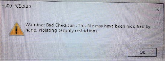
Не получилось – делай бэкап ещё раз. Полученный бэкап хранится по пути в Windows 10: C:\Users(имя_пользователя)\Config600 3.3\Configs. Делаем копию папки, не забывая поменять имя.
Переходим в вкладку Advanced Setup -> Security:
Далее либо через веб-интерфейс, либо через сам Floboss:
- Подходим к вычислителю Floboss и в главном меню выбираем пункт 5 SYSTEM SETTINGS

- Выбираем подменю SYSTEM STATUS

- Нажимаем кнопку Chng.
- Когда появится подсказка Enter Code: (Введите код:), вводим свой код доступа (коды по умолчанию можно посмотреть там же в PCSetup)

- Нажимаем 1, чтобы выбрать холодный старт (COLD START), а затем еще раз 1 для подтверждения.
- Вычислитель FloBoss S600 выполнит перезапуск.
- Эта операция приведет к появлению стартового меню:

Не забываем проверить битность.
Открываем Config Transfer, в вкладке Transfer должны быть те же значения, что и при снятии бэкапа конфигурации.
Открываем вкладку Send, выбираем нужную правленную конфигурацию:

Нажимаем кнопку SEND, после чего начнется загрузка проекта. После успешной загрузки появится окно на английском языке, что проект удачно загружен.
Нажимаем OK и подходим к вычислителю Floboss.
Вычислитель Floboss во время загрузки проекта.

После вычислитель перезагружается:

Ждем пока не появится стартовое меню, такое же как перед началом загрузки:

После того как появится это меню нажимаем 2- COLD START, далее соглашаемся с обнулением и перезагрузкой (2 Reset totals)


и ждем когда произойдет перезагрузка и появится главное меню.
Заходим и проверяем коэффициенты — в случае различий правки значений можно сделать через веб-интерфейс, либо напрямую с панели Floboss.
Готово.
Видео с процессом заливки проекта:
- Home
- Documents
- Floboss S600 RUS
ɇɨɦɟɪ ɮɨɪɦɵ $ ‘; əɧɜɚɪɶ Ʉɨɧɬɪɨɥɥɟɪ ɢɡɦɟɪɢɬɟɥɶɧɵɣ )OR%RVV 6 Ɋɭɤɨɜɨɞɫɬɜɨ ɩɨ ɷɤɫɩɥɭɚɬɚɰɢɢ 5HPRWH $XWRPDWLRQ 6ROXWLRQV
Upload: alvapi
Post on 18-Apr-2015
673 views
- Download
Embed Size (px)
DESCRIPTION
Контроллер измерительный FloBoss S600+. Руководство по эксплуатации.
TRANSCRIPT


S600+
: 2011 1-1
CHAPTER 1 –
FloBoss ™ S600+ («S600+»). S600+,
Config600 Pro ( A6169).
. . FloBoss S600+ (S600)
.
S600+ .
1.1 1-1 1.2 ( ) FloBoss™ S600+ 1-2 1.3 Config600 1-5
1.3.1 Config600 Lite 1-6 1.3.2 Config600 Lite+ 1-6 1.3.3 Config600 Pro 1-7
1.4 1-8 1.4.1 1-8
1.1 :
1
S600+ ( )
(Config600). 2
S600+,
. .
3
,
, .
4
/
/ ,
, / .
5
, , .
6 —
— .
7
, « » « » .

S600+
1-2 : 2011
8
,
. A
. B
;
.
, .
1.2 ( ) FloBoss™ S600+
1-1. FloBoss S600+
FloBoss S600+
, .
S600+ , ,
. S600+
. S600+ ,
, .
/ , . ,
, .
/ — 3. ( )- 10.
,

S600+
: 2011 1-3
. — 2. . S600+
– , , , Annubar V-
Cone®, ; : ,
— — . S600+
: ( )
Ethernet 10Base-T 100Base-T ( Modbus TCP,
Ethernet).
. Ethernet (P190), Ethernet
S600, S600+.
HART® 12- HART,
— (point-to-point), (multidrop) 50 HART- ( ).
— .
, , (
Windows® Internet Explorer®, 5 ). EIA 232
(RS-232). EIA 422/485 (RS-422/RS-
485) ( 57 600 / ) 2- EIA 485 (RS-485) ( 57 600 / )
, ( , SCADA-
), (DCS), .
( )
.
: • Q.Sonic® • • ModbusTCP
Daniel,

S600+
1-4 : 2011
• « »
• Modbus EFM, Modbus RTU, ASCII Modbus, Modbus Ethernet Modbus-TCP
, Modbus- TCP.
Daniel Daniel Sick Daniel
. .
1-2.
1-3. /

S600+
: 2011 1-5
1-4.
1.3 Config600™
. . — 3 . . . . K- — . / . . . .
, , .
. . . .
. S600+ ,

S600+
1-6 : 2011
IPL600 IPL 600 (“Interactive Program Loader”) .
IPL600 , /
( , Modbus, , LogiCalc). IPL 600
, , Config600.
Config Transfer/IPL600
Config600 (A6169).
1.3.1 Config600 Lite Config600 Lite
, / , ,
.
. Config600 Lite S600+/
Config600 Lite .
, , , , .
Modbus,
Modbus, .
( ), , .
, ,
.
. —
.
1.3.2 Config600 Lite + Config600 Lite +
Config600 Lite, .
Config600 Lite+ .

S600+
: 2011 1-7
.
, , , ,
. Modbus,
Modbus,
( ), , .
, ,
. .
—
1.3.3 .Config600 Pro Config600 Pro
, , ,
. Config600 Pro
.
. , ,
, , .
Modbus, Modbus,
( ),
, . ,
, . .
—
—
. .
LogiCalc.
. Config600 Pro .

S600+
1-8 : 2011
1.4 ,
: www. EmersonProcess.com/Remote, 1-1. :
FloBoss ™ S600+ S600 D301151X412
Config600 ™ Config600 D301164X012
Config600™ A6169 D301220X412
1.4.1 FloBoss S600+ ,
GPL, GPL2, GPL3, LGPL, OpenSSL, SSLeay, zlib, libzip2,
Apache. : U-Boot, Linux, glibc, — Apache,
mod_sll, mod_alias, mod_rewrite, OpenSSL, BusyBox, ntpclient, tar32, JFFS2.
— S600+ ( S600SRCOPEN).
. ,
Remote Automation Solutions SupportNet.
, OpenSSL OpenSSL Toolkit
(http://www.openssl.org). ,
(Eric Young) ([email protected]).

S600+
: 2011 2-1
CHAPTER 2 –
S600+, , ,
,
2.1 2-1 2.2 2-2 2.3 , 2-2 2.4 S600+ 2-3 2.5 2-7
!
(
) , /
, .
2.1
S600+ .
.
, , ,
S600+
. , ,
S600+.
S600+ , .
:
,
(
/ ).
, .
.
/ ( )
2-1 S600+.

S600+
2-2 : 2011
2-1. S600+
. , / S600+, :
« », 4 , , 4 , , 22
2,5 .
2.2 . S600+
( ) , ,
.
– .
!
, .
,
.
2.3 , S600+
:
(4- 6 ), ,
.
5.5 (5 BA)
.

S600+
: 2011 2-3
2.5 , ,
2.4 S600+
FloBoss S600+, , .
2.4.1 S600+ S600+
, .
. ,
, .
2.4.2 , ,
S600+.
1. , S600+ .
2. 2.5 ,
. 2-2
2-2.
. .
3. S600+ 4 ,
, .
2-3.

S600+
2-4 : 2011
2-3.
4.
. 2-4.
.
.
. S600+.
.

S600+
: 2011 2-5
2-4. 5.
5.5 (5
BA).
2-1.
85 (3,35 ) x 269 (10,59 ) x 28 (1,10 )
84,5 (3,327 ) x 270 (10,63 ) x 303,8 (11,94 )
66 (2,6 ) x 150 (5,9 )
110 (4,33 ), 25 (0,98 )
10 (0,39 )
300 (11,81 )

S600+
2-6 : 2011
2-5.
2.4.3 ,
, :
1. .
. 483 (19 ) 311 (12.25 )
S600+, .
2. 2-6 2-1, , 7 (0.276 )
. S600+.
±3 (0.12 ).

S600+
: 2011 2-7
2-6.
. S600+
S500 869.
3. , 3 (0.12 ).
, .
2-7.
!
,
.
2-7.

S600+
2-8 : 2011
4. .
5.
5.5 (5 BA).
6. , — . ,
, 3 (0.12 ).
2.4.4
S600+:
1. ( ) .
!
. . —
. 2. ,
, .
3.
.
4. 2.5 . 180 .
!
. .
2.5 S600+
. ,
.
. / ,
.
!
.
, .
, , ,
.

S600+
: 2011 2-9
, , :
1. , , , S600+ .
2. , , , . 2-8.
2-8.
3. .
. 2-9 2-10.
2-9.

S600+
2-10 : 2011
2-10. ,
( )
( ) S600+
( S600+), : 1 (
), 1 25- — — EMISTOP
( 25- A / ),
1 37- — — EMISTOP ( 37- B
/ ), 3 — (
13 ) 3 — (
10 ) 1 — (
6,5 ) 2 M3 x 6 (
S600+) 5 ( ) TY523 Ty-Rap
( , ).

S600+
: 2011 2-11
. .
S600+ ( , ),
.
.
:
1. « » / ( . 2-11).
2-11. /
2. , S600+,
/ , , 1 ( . 2-12).

S600+
2-12 : 2011
2-12.
. S600+,
2-12, , .
3. S600+ 2 M3 x 6 .
4. 25- 37- EMISTOP ( . 2-13) A B,
, / ( . 2-14).
2-13. EMISTOP 5.
. 6. —
A / . —
B C ( . 2-14).

S600+
: 2011 2-13
2-14. —
/ 7. —
— COM3 COM 4 ( . 2-15).
2-15. — COM
—
—
—
—
25- EMISTOP
37- EMISTOP

S600+
2-14 : 2011
8. — COM 5, 6, 7 —
– Ethernet ( . 2-16).
2-16. — , COM Ethernet
S600+
.
—
—

S600+
: 2011. 3-1
CHAPTER 3 –
.
3.1 (P152) 3-1 3.2 3-4
3.2.1 3-4 3.2.2 3-4
3.3 3-5 3.3.1 EIA-232 (RS-232) 3-6 3.3.2 EIA-422 (RS-422)/EIA-485 (RS-485)
3-7 3.3.3 Ethernet LAN 3-7 3.3.4
3-7 3.4 3-8 3.5 USB 3-9 3.6 3-9
!
,
( ) , /
, .
3.1 (P152) P152
. .
CPU , 3-1. 3-2
P152, 3-3 3-4- P152.
; . 3.5,
« ». , , 1,5 .
(0,0023 . ). 1,75 1,65 . (0,0027-
0,0025 . ). 1,5 . (0,0023 . ).
.
!
, « »
S600+ .

S600+
3-2 : 2011.
3-1.
3-2.
TB-1
Ethernet
COM 3
COM 4
RS-485 ( COM 9
COM 12)
USB
Ethernet
COM 5
COM 6
COM 7.
A (-) COM 12

S600+
: 2011. 3-3
SERVICE
SERVICE
SERVICE
SERVICE
N/C
N/C
N/C
N/C
ETHERNET
RS422/485
0V
RS232
0V
RS232
SERVICE
12
3
4
5
6
7
8
1
2
3
4
5
6
7
8
1
2
3
4
5
6
7
8
1
2
3
4
5
67
8
1
2
3
4
5
6
7
8
9
10
11
12
13
RS422/485
RS422/485
N/C
N/C
N/C
N/C
ETHERNET
1
2
3
4
5
67
8
14
15
16
17
18
19
20
RS485
RS485
RS485
RS485
SERVICE
SERVICE
USB
1
2
3
4
CPU MODULE (P152)
3-3.
LCD
& S
ETU
P
3-4.

S600+
3-4 : 2011.
3.2 P152 CPU
5 .
TB-1. TB-1 3-1. S600+
30 , 2 . S600+
20 32 . 6 100
. , .
152 ( 2.5 ),
.
15 24 . ,
. .
3-1. TB-1 ( )
1 +24 , , 2 0 ( ) 3 +24 , , (500 ) 4 +15 , , (100 ) 5 0 ( )
3.2.1
, 6, 7 8
TB-1. TB-1 3-
2. 5 .
.
. 2.5
. 1 , – 30 , – 30 ,
«C».
3-2. TB-1 ( )
6 7 8

S600+
: 2011. 3-5
3.2.2 ,
P152, BIOS CMOS ( ) .
3,0 , 1500 — ,
.
(S600+). ,
S600+ . :
. , , S600+
1. S600+. 2. .
. , S600+.
3. . 4. ( . 3-2),
. 5.
, ( 3-2).
6. .
. , 3-5 ,
.
7. ( , 3 , 1500 — ,
S600+BATTERY). 8.
S600+, .
9. .
. , .
10. S600+.

S600+
3-6 : 2011.
3.3
( , Ethernet- USB- ).
.
COM 1-7 1-7, , , S600.
S600+ COM 1- 7 ,
. 3 4 . COM 1
( ) Config Transfer.
COM 9-12 S600+ RS-485 ( COM 9 COM12),
( . 3-1).
3-3.
Network 1 NTWK1 Ethernet Network 2 NTWK2 Ethernet Comm 4 COM4 EIA 232 (RS-232) Comm 3 COM3 EIA 232 (RS-232)
Comm 5, 6 7 TB2, TB3, TB4 EIA 422 (RS-422) EIA 485 (RS-485) Comm 9 TB6 Comm 10 TB6 Comm 11 TB6 Comm 12 TB6
USB
,
Comm 2, 5, « ».
3.3.1 EIA 232 (RS-232) P152
EIA-232 (RS-232D). RJ-45 FCC-68
COM3 COM4. COM3 COM4 3-4. 3-5
.
9- D- 25- D- . –
2400 57600 .

S600+
: 2011. 3-7
3-4. COM3 COM4
1 2 DTR 3 RTS 4 TX 5 RX 6 CTS 7 DSR 8 DCD
3-5.
. , 19200 ,
15 (50 ).
.
, .
3.3.2 EIA 422 (RS-422)/EIA 485 (RS-485) (multi-drop)
P152 EIA-422 (RS-422)
EIA-485 (RS-485). 38400 1200 (4000 ).
, TB-2, COM5, COM6 COM7. COM5, COM6 COM7 3-5 .
. RS-
485, .
( ), .

S600+
3-8 : 2011.
3-5. COM5, COM6 COM7
1 B 2 A 3 Z
COM5
4 Y 5 B 6 A 7 Z
COM6
8 Y 9 B 10 A 11 Z
COM7
12 Y
3.3.3 Ethernet Ethernet NTWK1 NTWK2
(Local Area Network, LAN) Ethernet. 100
100BaseT. RJ-45
FCC-68.
.
3.3.4 COM3 4
FloBoss S600 (COM2).
COM3-4 .
, , ,
.
S600+
S600+ .
( : 3080017) 9- .
, , 3-6.
. S600+,
5 (15 ).

S600+
: 2011. 3-9
3-6.
3.4 3-6 .
. .
. , ,
, .
3-6. / /
P1
P2 « »
P3 ( — 1 )
P4 ( )
P5 ( )
P6 ( )
P7 COM5 ( 1-2: )
P8 COM6 ( 1-2: )
P9 COM7 ( 1-2: )
P10
RS-422/RS-485 COM5. 1-2, 4-5, 7-8, 10-11 RS-422
14-15
P11 RS-422/RS-485 COM5. 1-2, 4-5, 7-8, 10-11 RS-422
14-15

S600+
3-10 : 2011.
/
P12
RS-422/RS-485 COM5. 1-2, 4-5, 7-8, 10-11 RS-422
14-15
P13 COM10 (1-2: ) P14 COM9 (1-2: ) P15 COM12 (1-2: ) P16
P17
TB6
1-2 3-4 – 2-3 5-6 –
P18 COM11 (1-2: )
P20 , 2-3 —
P26 —
P27 — (NAND/NOR)
3.5 USB USB 2.0
, , USB- — .
S600+, — . » / » (Tech/Engineer) > USB.
. 5, « ».
3.6 ,
: www. EmersonProcess.com/Remote,
3-7.
:
FloBoss ™ S600+ S600 D301151X412

S600+
: 2011. / 4-1
CHAPTER 4 – /
( PRT ) / ,
( ) HART- .
( ) 148, / .
!
, (
) , / ,
.
4.1 / (P144) 4-1 4.1.1 (ANIN) 4-3 4.1.2 (DAC) 4-5 4.1.3 (DIGIN) 4-6 4.1.4 (DIGOUT) 4-8 4.1.5 (PULSEIN) 4-9 4.1.6 (PULSEOUT) 4-10 4.1.7 « » (RAWOUT) 4-11 4.1.8 4-12 4.1.9 PRT/RTD 4-13 4.1.10 4-14
4.2 ( ) (P154) 4-16 4.2.1 (DIGIN) 4-18 4.2.2 (DIGOUT) 4-20 4.2.3 4-21 4.2.4 (PULSEOUT) 4-22 4.2.5 4-22 4.2.6 4-24
4.3 HART (P188) 4-25 4.4 (P148) 4-27
2 . (0,003 . ). —
.
!
, « »
S600+ .
4.1 / (P144) / (P144)
, . 12
(ANIN), 4 (DAC), 16 (DIGIN), 12 (DIGOUT), 4 (PULSEIN), 5 (PULSEOUT), 3
( , FREQUENCYIN) 3
( , PRT/RTD). D- «

S600+
4-2 / : 2011.
» . SKT-A, SKT-B SKT-C ( . 4-1).
4-1. / (P144)
4-2. / ( )
SKT-A ANIN 1-10 DAC 1-4
SKT-C DIGIN 7-16 DIGOUT 3-12 PULSEIN
SKT-B AININ 11-12 DIGIN 1-6 DIGOUT 1-2 FREQUENCYIN PULSEOUT
(P148)

S600+
: 2011. / 4-3
4-3. /
4.1.1 (ANIN) /
— ,
(Analog Input, ANIN). (ANIN 1-10) 0 5.25
0 22 . ,

S600+
4-4 / : 2011.
(ANIN 11 12). , 12 .
ANIN 1-10 ,
.
, . 4-4 4-5.
!
.
ANIN 1-5 – .
ANIN 6-10 – .
4.1.10.
4-4. (
)
4-5. (
)
ANIN , SKT-A SKT-B,
P144. CH1 CH10 SKT-A, CH11 CH12 – SKT-B.
4-1 4-2.

S600+
: 2011. / 4-5
4-1. SKT-A
8 . — 1 21 . — 2 9 . — 3 22 . — 4 10 . — 5 20 1-5 11 . — 6 24 . — 7 12 . — 8 25 . — 9 13 . — 10 23 6-10
4-2. SKT-B
8 . — 11 ( ) 7 . — 12 ( ) 20
4.1.2 (DAC) /
( — , ).
. 650
. ,
4-6 4-8. ,
SKT-A, P144. — ,
/ , 4-3.
4-6. ( S600+)

S600+
4-6 / : 2011.
4-7. ( )
4-8. ( S600+)
4-3. — SKT-A
1 — 1 +15 14 — 1
2 — 1 = 0 15 — 2 +15 3 — 2
16 — 2 = 0 4 — 3 +15 17 — 3
5 — 3 = 0 18 — 4 +15 6 — 4
19 — 4 = 0
4.1.3 (DIGIN) / 16
(Digital Inputs, DIGIN) . 4
. 4-9 4-10. – 1 .
DIGIN , SKT-B SKT-C,
P144. DIGIN 4-4 4-5.

S600+
: 2011. / 4-7
. ( , 17 SKT-B)
24 . . DIGIN ( ., 13 SKT-B)
« » ( ).
4-9. ( )
4-10. ( )
4-4. SKT-B
13 . — 1 14 . — 2 15 . — 3 16 . — 4 17
( ) 1-4
18 . — 5 19 . — 6

S600+
4-8 / : 2011.
4-5. SKT-C
19 . — 7 18 . — 8 17 ( ) 5-8 16 . — 9 15 . — 10 14 . — 11 13 . — 12 12 ( ) 9-12 11 . — 13 10 . — 14 9 . — 15 8 . — 16 7 ( ) 13-16
4.1.4 (DIGOUT) / 12
. (Digital Output, DIGOUT) .
100 24 . . 0.5 . .
, . , , ,
. 4-11 4-12.
DIGOUT , SKT-B SKT-C,
P144. DIGOUT 4-6 4-7.
4-11. ( )
4-12. ( 24 )

S600+
: 2011. / 4-9
4-6. SKT-B
36 . — 1 37 . — 2
4-7. SKT-C
37 . — 3 36 . — 4 35 ( ) 1-4 34 . — 5 33 . — 6 32 . — 7 31 . — 8 30 ( ) 5-8 29 . — 9 28 . — 10 27 . — 11 26 . — 12 25 ( ) 9-12
4.1.5 /
( ) (P148), .
, .
, , .
A B.
1 10 .
.
.
,
/ ..
3,5 24 . 4-13 4-14. NAMUR , ,
..
, Mercury ( Spectra-Tek) F 106
ST106, Instromet MK15, Faure Herman FH71 2- , Faure Herman FH71 3- , ITT Barton 818U, Daniel 1838.
4-8.

S600+
4-10 / : 2011.
4-13. ( P148, 12 )
4-14. ( P148, 24 )
4-8. SKT-C
4 ./ . .- 1 + 23 ./ . .- 1- 3 ./ . .- 2 + 22 ./ . .- 2- 2 ./ . .- 3 + 21 ./ . .- 3- 1 ./ . .- 4 + 20 ./ . .- 4-
4.1.6 /
(PULSEOUT),
. 4-15. PULSEOUT
4-9.
4-15.

S600+
: 2011. / 4-11
4-9. PULSEOUT SKT-B
30 . — 1 31 . — 2 32 . — 3 33 . — 4 35 1-4 34 . — 5 12 5
4.1.7 « » (RAWOUT) /
« » ,
. 4-15. 1 ,
« » 1 , « » ,
20 . 4-10 « »
SKT-C
4-16. « »

S600+
4-12 / : 2011.
4-10. SKT-C
24 « » 5
4.1.8 / , — .
0 10 . /
, . 4-17 4-18.
P144, SKT-B.
4-11.
4-17. ( )
4-18. ( )
. Micro Motion Solartron
, .

S600+
: 2011. / 4-13
4-11. SKT-B
9 . — 1 + 27 . — H1- 10 . — 2 + 28 . — H2- 11 . — 3 + 29 . — H3-
4.1.9 ( , PRT/RTD)
/ (Platinum Resistance Thermometer,
PRT) (Resistance Temperature Detector, RTD).
PRT/RTD 4- A,
BS EN 60751:1996. – –100 +200°C ( –148 +392°F). S600+
PRT/RTD,
DIN ( 0,00385 / ).
( 0,003926 / ).
— (
A, B, C, R0). DIN 43760 c , ,
. C AMERICAN ( )
, , .
PRT/RTD Config 600.
4-19 . PRT/RTD
4-12.
4-19. (PRT)
(RTD)

S600+
4-14 / : 2011.
4-12. PRT SKT-B
4 PRT — 1 I + 1 PRT — 1 U + 21 PRT — 1 U — 24 PRT — 1 I — 5 PRT — 2 I + 2 PRT — 2 U + 22 PRT — 2 U — 25 PRT — 2 I — 6 PRT — 3 I + 3 PRT — 3 U + 23 PRT — 3 U — 26 PRT — 3 I —
4.1.10 4-13
. .
, .
. — / P144
Link 2 (ON). (MUX)
Link 2 (OFF).

S600+
: 2011. / 4-15
4-13. /
— LK1 — —
( . 4-14) LK2 — — LK3 — LK10 (MUX) – . 4-14 LK11 / – LK12 / LK13, LK14, LK15 .
— LK161 1 — 1 — LK171 2 — 2 — LK181 3 — 3 — LK191 4 — 4 — LK201 5 — 5 — LK211 6 — 6 — LK221 7 — 7 — LK231 8 — 8 — LK241 9 — 9 — LK251 10 — 10 — LK26, LK27, LK28 . LK29, LK30 1-2/2-3 (2-3). 2-3.
LK31 . 01 — .. 01 — LK32 .. 02 — .. 02 — LK33 .. 03 — .. 03 —
1 1 .
LK16 LK19 . LK21 LK25 .

S600+
4-16 / : 2011.
4-14.
LK3 LK4 LK5 LK6 LK7 LK8 LK9 LK10 0 1-2
1 1-2
2 1-2 3 1-2 4 1-2 5 1-2 6 1-2 7 1-2 8 2-3
9 2-3
10 2-3 11 2-3 12 2-3 13 2-3 14 2-3 15 2-3
4.2 ( ) (P154) (
) P154 -, ,
, . ,
,
. , . 32 , 12
, 2 ( ) 4 . 4-22
.
. .
D- .
SKT-D, SKT-E SKT-F. 4-20.

S600+
: 2011. / 4-17
4-20. (P154)
4-21.

S600+
4-18 / : 2011.
1142
153
168
209
211022
20212223242526272829
3132333435
3637
37363534333231302928272625245
0V
SKT D
SKT E
SKT F
DIG OUT 1+
DIG OUT 4+
COMMON GND
DIG OUT 5+
DIG OUT 6+
DIG OUT 7+
DIG OUT 8+
COMMON GND
DIG OUT 9+
DIG OUT 10+
DIG OUT 11+
DIG OUT 12+
COMMON GND
175
1864
11231213192425
123456789
10
13141516171819
191817161514131211109874
233
222
211
20HITHIT
SKT D
SKT E
SKT F
SWITCH 1 —
SWITCH 2 —
SWITCH 3 —
SWITCH 4 —
COMMON + VE
— OUTPUT
GND
GND
GND
GND
GND
DIG IN 17 —
DIG IN 18 —
DIG IN 19 —
DIG IN 20 —
COMMON + VE
DIG IN 5 —
DIG IN 6 —
DIG IN 7 —
DIG IN 8 —
COMMON + VE
DIG IN 9 —
DIG IN 10 —
DIG IN 11 —
DIG IN 12 —
COMMON + VE
DIG IN 13 —
DIG IN 14 —
DIG IN 15 —
DIG IN 16 —
COMMON + VE
+ DUAL PULSE- CHANNEL 1
+ DUAL PULSE- CHANNEL 2
+ DUAL PULSE- CHANNEL 3
+ DUAL PULSE- CHANNEL 4
+DENSITY 1
—
RAW PULSE +
INPUT 1 —
DIG OUT 2+
DIG OUT 3+
3K3
3K3
3K3
0V
LINKS
RAW PULSE +
INPUT 2 —
RAW PULSE +
INPUT 3 —
PIM LOOP +
INPUT —
+DENSITY 2
—
DIG IN 25 —
DIG IN 26 —
DIG IN 27 —
DIG IN 28 —
COMMON + VE
DIG IN 29 —
DIG IN 30 —
DIG IN 31 —
DIG IN 32 —
COMMON + VE
PULSE OUT 1+
PULSE OUT 2+
PULSE OUT 3+
PULSE OUT 4+
COMMON GND
DIG IN 1 —
DIG IN 2 —
DIG IN 3 —
DIG IN 4 —
COMMON + VE
DIG IN 21 —
DIG IN 22 —
DIG IN 23 —
DIG IN 24 —
COMMON + VE
OV
OV
OV
+24V
+24V
PULSE OUT 2+
+24V
+24V
+24V
+24V
+24V
+24V
+24V
4-22.
4.2.1 (DIGIN) 32 (Digital
Inputs, DIGIN) .
4 . – 1 .
DIGIN , SKT-E SKT-F,
P154. DIGIN 4-15 4-16.

S600+
: 2011. / 4-19
. ( ., 17 SKT-E)
24 . . DIGIN ( ., 13 SKT-E)
« » ( ).
4-23 4-24.
4-23. (
)
4-24. ( )
4-15. SKT-E
13 . — 1 14 . — 2 15 . — 3 16 . — 4 17 ( ) 1-4 18 . — 5 19 . — 6 1 . -17 2 . -18 3 . -19 4 . -20 5 ( ) -17-20 6 . -21 7 . -22 8 . -23 9 . -24 10 ( ) 21-24 20 . -25 21 . -26 22 . -27 23 . -28 24 ( ) 25-28

S600+
4-20 / : 2011.
25 . -29 26 . -30 27 . -31 28 . -32 29 ( ) 29-32
4-16. SKT-F
19 . — 7 18 . — 8 17 ( )
5-8 16 . — 9 15 . — 10 14 . — 11 13 . — 12 12 ( )
9-12 11 . — 13 10 . — 14 9 . — 15 8 . — 16 7 ( )
13-16
4.2.2 (DIGOUT) 12
. (Digital Output, DIGOUT) .
100 24 . . 0.5 . .
, . , , ,
. DIGOUT 1 2
SKT-E, 3 12 – SKT-F. DIGOUT 4-17 4-18.
4-25 4-26.
4-25. ( )

S600+
: 2011. / 4-21
4-26. ( 24 )
4-17. SKT-E
36 . — 1 37 . — 2
4-18. SKT-F
37 . — 3 36 . — 4 35 ( ) 1-4 34 . — 5 33 . — 6 32 . — 7 31 . — 8 30 ( ) 5-8 29 . — 9 28 . — 10 27 . — 11 26 . — 12 25 ( ) 9-12
4.2.3
, . , ,
. A B.
1 10 . .
. 4-19.
4-27.
4-27. ( P148, 24 )

S600+
4-22 / : 2011.
4-19. SKT-F
4 . .- 1 + 23 . .- 1 — 3 . .- 2 + 22 . .- 2 — 2 . .- 3 + 21 . .- 3 — 1 . .- 4 + 20 . .- 4 —
4.2.4
(PULSEOUT), .
PULSEOUT 4-20.
4-28.
4-28.
4-20. PULSEOUT SKT-E
31 . — 1 32 . — 2 33 . — 3 34 . — 4 35 1-4
4.2.5 ,
. 0 10 .
SKT-D 4-21. 4-29 4-30.
. Micro Motion, 4-29 4-30,
Solartron, ,
.

S600+
: 2011. / 4-23
4-29. (
).
4-30. (
).
. Micro Motion Solartron
, .
4-21. SKT-D
9 . — 1 + 21 . -H1- 10 . — 2 + 22 . -H2-

S600+
4-24 / : 2011.
4.2.6
. .
4-22 P154
— LK1
( . 4-23), LK2 (MUX) LK11 (MUX)
: 1 2 3 4 5 6 7 8 9 10 11 12 13 14 15 LK3 LK4 LK5 LK6 LK7 LK8 LK9 LK10 1-2 2-3
LK12 1-2 3,465 2-3 5 – Vcc
( ) LK13/14 1-2 — RS-422 2-3
3 — LK15/16 : +ve Vcc -ve
0
4-23. :
2
11
3-10
—
(MULTIDROP)
(MUX)

S600+
: 2011. / 4-25
4.3 HART- (P188) HART 12- HART- .
8 ( 50 ).
— (MULTIDROP) .
D, P188. A
25- , B – 25- ,
4-31. 4-24 4-25
(SKT-A SKT-B, ). 4-32 4-34
.
4-31. HART- (P188)
4-24. P188 ( A) A
A
1 + 1 1- 14 2 + 2 2- 15 3 + 3 3- 16

S600+
4-26 / : 2011.
A
A
4 + 4 4- 17 5 + 5 5- 18 6 + 6 6- 19 7 + 7 7- 20 8 + 8 8- 21
4-25. P188 ( )
B
B
9 + 13 9- 25 10 + 12 10- 24 11 + 11 11- 23 12 + 10 12- 22
! HART 270 .
4-32. HART

S600+
: 2011. / 4-27
4-33. HART
4-34. HART
4.4 (P148) (P148)
/ , .
1 4 / , 2 5 .
/ — , ,
, , .
,
( — ).

S600+
4-28 / : 2011.
[ .]

S600+
: 2011. 5-1
CHAPTER 5 –
S600+, , ,
. .
5.1 5-1 5.2 5-2 5.3 5-2
5.3.1 (F1 — F4) 5-3 5.3.2 5-3 5.3.3 5-3 5.3.4 5-3 5.3.5 5-4
5.4 5-5 5.5 5-7
5.5.1 DISP 5-9 5.5.2 5-9 5.5.3 5-9 5.5.4 5-9
5.6 5-10 5.7 5-11 5.8 5-12 5.9 5-12 5.10 . 5-13 5.11 (EXPT) 5-13 5.12 Print 5-13 5.13 , (USB) 5-15 5.14 5-16 5.15 5-17
5.1 S600+ , —
. FloBoss S600 5-1.
5-1.
—
F1-F4

S600+
5-2 : 2011.
5.2
(Comm 2) CONFIG 600 .
. EIA-232 (RS-232D) RJ-12
.
5-1. 15-
D- 3-7 3.3.4.
5-1.
1 (RTS) 2 (TX) 3 4 5 (RX) 6 (CTS)
5-2.
5.3
, ,
. : : . — : . — : . — :
5.3.1 (F1 — F4)
: F1 – F4.
. 5.9.

S600+
: 2011. 5-3
5.3.2
« » (MENU) ( . 5-1).
( , , ), .
,
. « » (MENU),
. « » (MENU)
. .
5.3.3
. (0-9), « » (–),
(.).
, 0 9: .
: , S600+ .
« », .
5.9 .
5.3.4
:
. (EXPT): « » (EXPT) .
, , , ( 20 ),
. (CLEAR): « »
(CLEAR) , .
« » (CLEAR), ( ).
(DISP): « » (DISP), .
/ (Status/ID) .
(CHNG): « » (CHNG),
.
. , (*).

S600+
5-4 : 2011.
(PRINT): « » (PRINT), ,
,
, . (Enter, ):
« » (CHNG)
.
5.3.5
F (MENU)
– (View) (Accept). (
) . ,
( ).
.
S600+ , , , .
, ,
(View)
(Accept). , .
, .
, (Accept), . , .
, , . ,
.
« » Accept, S600+,
.
. ,
. ,
.
. , . 8, « ».

S600+
: 2011. 5-5
5.4 — — S600+
— . ( ) .
5-3 S600+:
1* « » (FLOW RATES) 2* « » (TOTALS) 3* « » (OPERATOR) 4* « / » (PLANT I/O) 5* « » (SYSTEM SETTINGS) 6* « » (TECH/ENGINEER) 8* « » (CALCULATIONS)
5-3. S600+
, .
1 8 . (*),
( , 1* « » (FLOW RATES)) ,
. (.) ( , 1. STR01 UVOL FR), ,
, .
S600+ , , .
, . —
(*) . .
..
STR01 COR PRESS «
» (In Use Value): 0.000000 barq » » (Mode Status): « » (CALCULATED) *
P20.1 <of 4>——-W
5-4.
,
» / «; (20.1)
—
.

S600+
5-6 : 2011.
» / «
» / » ( 5-4) .
/ ( 20.1),
(<of 4>), .
S600+ . , ,
. – « » .
20.1
20- . « » (DISP)
( 5.5.1. ).
S600+
» / » ( . 5-4),
( ) .
P M S « » (STANDBY) ( «
») D « » (DUTY) ( «
») W web- (
)
5.5. . , ,
, , ,
. ,
, .
5-5 S600+ , .
3.4 (, )

S600+
: 2011. 5-7
1* « » (FLOW RATES) 2* « » (TOTALS) 3* « » (OPERATOR) 4* « / » (PLANT I/O) 5* « » (SYSTEM SETTINGS) 6* « » (TECH/ENGINEER) 8* « » (CALCULATIONS)
1. STR01 «
» UVOL FR 2. STR01 « »
VOL FR 3. STR01 « » MASS FR 4. STR01 « .
» ENERGY FR
« » (FLOW RATE) STR01 CVOL FR 9,45 « . . » Sm3/h
P2.1 <of 2>———
5-5. S600+ S600+ ( 5-6)
, (*), :
1* « » (FLOW RATES) 2* « » (TOTALS) 3* « » (OPERATOR) 4* « / » (PLANT I/O) 5* « » (SYSTEM SETTINGS) 6* « » (TECH/ENGINEER) 8* « » (CALCULATIONS)
5-6. S600+ ( 5-7),
, . .
1. STR01 « » UVOL FR 2. STR01 « » VOL FR 3. STR01 « » MASS FR 4. STR01 « . » ENERGY FR
5-7. 5-8 ,
. ( –
1). , .
, .
« » (FLOW RATE)
STR01 CVOL FR 9,45 « . . » Sm3/h
P2.1 <of 2>———
5-8.
.

S600+
5-8 : 2011.
, .
5-5, 1, 2 , 5-8.
,
. , , 5-8, ,
.
5-9 ,
. , .
« » (FLOW RATE) STR01 CVOL FR 9,45 « . . » Sm3/h
P2.1 <of 2>———
« » (FLOW RATE)
STR01 MASS FR 12.01 « / » t/h
P3.1 <of 2>———
5-9. ,
, , « » :
5.4.1 « » (DISP) « » (DISP) (
) :
1. « » (DISP) ( , 25.6).
. , ( , «25»),
.
2. » » (Enter). .

S600+
: 2011. 5-9
5.4.2 , « »
(MENU). « » (MENU) .
, (
) « » (MENU), .
. , « » (CHNG),
, « » (MENU) ,
« » (CLEAR) ( ) « » (Enter)
( ). 5.4.3
B , S600+, ,
.
5.4.4 ,
, , .
, . : 0 ( )
9 ( ). , . 0
.
— Config 600.
S600+ 7,
« » Config600 ( A6169).
5.5
, . ,
(
5-10): STR01 «
1» DENS SELECT » » (Status): » » (CORIOLIS) * _
P19.1 <of 11>——-
STR01 « 1»
DENS SELECT » » (Status): » » (Enter Code): _
P19.1 <of 11>——-
1.» «(CORIOLIS) 2. » » (I/O)

S600+
5-10 : 2011.
5-10. :
« » (CHNG). ,
5-10. , . ,
. ,
5-11. .
, .
.
1. . , ,
5-10. 2. ,
. , 5-11.
3. , . , 5-11
. , /
«W», web- .
5.6 ,
, S600+.
: 1. (
5-12) « » (CHNG).
, 5-12. 2. .
, , 5-12.
« » (CONFIRM) « » (SET TO): » / » (I/O) 1. » » (YES) 2. » » (NO)
STR01 DENS SELECT » » (Status): » / » (I/O) *
P19.1 <of 11>——-

S600+
: 2011. 5-11
« 2» ADCO2 I/O01 ADC 02 » , » (Keypad Value): 100.000 !* » » (Measured Value): -24.998 !
P2.1 <of 2>———
« 2» ADCO2 I/O01 ADC 02 » , » (Keypad Value): » » (Enter Code):——— » » (Measured Value): -24.998 ! P2.1 <of 2>———
« » (CURRENT VALUE): 100.000 ! « » (NO ENTRY LIMITS): « » (ENTER NEW VALUE):
5-12. 3. ( – 99.999).
, 5-13.
. « » (Change) ,
, .
« » (CLEAR) , .
4. » » (Enter). ,
5-13. « » (CURRENT VALUE): 100.000 ! « » (NO ENTRY LIMITS): « » (ENTER NEW VALUE): 99.999
« 2» ADCO2 I/O01 ADC 02 » , » (Keypad Value): 99.999 !* » » (Measured Value): -24.998 !
P27.2 <of 4>———
5-13.
5.7. ( . 5.6).
. , .
1. . 2. « » (CHNG), ,
. .
, .
..

S600+
5-12 : 2011.
3. « » (CHNG). .
4. . 5.
. 6. ,
« » ( Enter).
7. « » (Confirm), . 1, , 2,
. .
. ,
, ,
, .
5.7
, , ,
S600+. :
. «–» ( ). :
1. . 2. . 3. .
, 2 3. , « »
(CLEAR). . « » (CLEAR)
. 5.8. (F)
— ,
(F1 – F4).
1. .. 2. (.). 3. (F1, F2, F3 F4),
.
. (F) , ,
» » S600+.
F .

S600+
: 2011. 5-13
5.8 (EXPT) (« .»
(EXPT)) .
, . Config 600
.
Config 600 ( A6169) (F1 Help) Config 600 ..
, :
1. . 2. « » (EXPT) (
«E»), . 3. » » (Enter).
, 0,00000009 , 9.0 9,
« .» (EXPT), -8 ( ) «Enter» ( ) .
5.9 S600+
, . S600+
web- ( . 6, « web- »).
« » (PRINT) « » (Print Options):
» » (PRINT OPTIONS)—- 1. » » (HELP) 2* » » (CONFIGURATION) 3* » » (REPORTS) 4* » » (COMMUNICATIONS) 5. » » (CURRENT ALARMS) 6* » » (LOGS) 7. » » (ABORT PRINTING)
5-14.
« » (PRINT) ,
. :
,
. ( 8).
. (.txt)
(CSV- ).

S600+
5-14 : 2011.
.
,
.
,
.
,
.
,
.
, .
,
.
, . Modbus Modbus,
( ) S600+.
.
:
1. , TXT 2. , CSV 3. 4. 5.
1. 2. 3.
1. Modbus
;
.
1. 2.
; .
5.10 , (USB) S600+ USB- , . USB-
,

S600+
: 2011. 5-15
, — .
. web- .
: 1. USB- ( — ) USB- . 2. « » (Tech/Engineer). 3. USB « » (Tech/Engineer).
« » (USB Report Control) ( 5-15).
1* « » (FLOW RATES) 2* « » (TOTALS) 3* « » (OPERATOR) 4* « / » (PLANT I/O) 5* « » (SYSTEM SETTINGS) 6* « » (TECH/ENGINEER)
8* « » (CALCULATIONS)
1. « » (DISPLAY SETUP) 2. » » (CONTRAST) 3. «
«(DATE & TIME): 4. « » (DISPLAY TEST) 5. » » (SECURITY) 6* « » (COMMUNICATIONS) 7. USB
« » (USB REPORT CTL)
» » (Status): » » (IDLE) * P204.1 <of 4>
5-15. « » (USB Report Control) 3 4 ( . 5-16)
, ( ) , ( ASCII,
CSV), ( , ).
« » (USB REPORT PROGRESS) » » (Value): 0 % P204.1 <of 4>
« » (USB REPORT FORMAT) » » (Status): » » (TEXT) P204.3 <of 4>
« » (USB
REPORT COMBINE) » » (Status): » » (NO) P204.4 <of 4>
5-16.
.
.
4. ,
(« » (USB Report Control)).
. ,
USB- ( -), .

S600+
5-16 : 2011.
5. « » (CHNG). 6. ,
.
7. , , .
« » (USB REPORT PROGRESS) » » (Value): 0 % P204.1 <of 4>
1. » «(ABORT) 2. « » (DUMP REPORTS) 3. «
» (DUMP ALARMS) 4. « » (DUMP EVENTS)
« » (CONFIRM)
« » (SET TO): « » (DUMP REPORTS) 1. » » (YES) 2. » » (NO)
5-17. 8. «1», .
« » (USB Report Progress)
.
!
USB- . USB-
, « » (USB Report Control) « »
(IDLE). .
« » (USB REPORT PROGRESS) » » (Value): 0 % P204.1 <of 4>
« » (USB REPORT CTL)
» » (Status): » » (IDLE) * P204.1 <of 4>
5-18. 9. ,
« » (USB Report Control) « » (IDLE).
« » (Menu), « » (Tech/Engineer).
5.11 S600+ 20
. , S600+ , .
, .
. web— .

S600+
: 2011. 5-17
1. « » (Cold Start) « » (Config Selector).
, ( 5-19).
1* « » » (WARM START) 2* « » » (COLD START) 3* «
» (NETWORK SETUP) 4. «
» (REFLASH
FIRMWARE) 5. «
» (CONFIG SELECTOR) 8*. « » (FACTORY SETUP)
1. (1) » -1″ (Serial-1) 2. (2) compact_prvr 3. (3) aga8 4. (4) aga3 5. (5) ISO-5167_2003 6. (7) dual_prover 7. (8) bidi-prover 8. » » (Next)..
1. » » (Previous).. 2. (9) compact_prvr 3. (10) aga8 4. (11) aga3 5. (12) » » (empty) 6. (13) » » (empty) 7. (14) » » (empty) 8. » » (Next)..
5-19. 2. ,
. « » (Cold Start). « »
, .
. , ,
« » (Cold Start).
5.12 web-
« » (Cold Start).
1. « » (Cold Start) « » (Network Setup).
« » (Network Setup). « web-
» (Webserver Setup). « SSL» (SSL Mode Setup) ( 5-20). 2. « Secure Socket Layer (SSL)-
» (SSL MODE SETUP) S600+.
. , 5-20 ,
. « SSL» (SSL Mode Setup)
5-22.

S600+
5-18 : 2011.
1* « » (WARM START) 2* « » (COLD START) 3* «
» (NETWORK SETUP) 4. «
» (REFLASH
FIRMWARE) 5. « » (CONFIG SELECTOR) 8*. « » (FACTORY SETUP)
1* « I/F 1» (NETWORK I/F 1) 2* « I/F 2» (NETWORK I/F 1) 4. « MODBUS» (MODBUS ADDRESS). 5. « » (PC SETUP COMMS) 6. « —
» (WEBSERVER SETUP) 7. « » GO BACK
« SSL» (SSL MODE SETUP) 1. «SSL » (SSL ENABLED) 2. «SSL » (SSL DISABLED)
5-20. 3. , «1».
web- , , «
» (Network Setup) ( . 5-21),
FloBoss S600+——— » , —
» (PLEASE WAIT WEBSERVER IS RESTARTING)
FloBoss S600+——— « SSL » (SSL MODE IS ENABLED)
1* « I/F 1» (NETWORK I/F 1) 2* « I/F 2» (NETWORK I/F 1) 4. « MODBUS» (MODBUS ADDRESS). 5. PC Setup» (PC SETUP COMMS) 6. « — » (WEBSERVER SETUP)7. « » GO BACK
5-21. 4. ,
6. : FloBoss S600+———
« SSL» (SSL MODE SETUP) « » (CURRENT ENABLED) 1. «SSL » (SSL ENABLED) 2. «SSL » (SSL DISABLED)
5-22.
, 2.

S600+
: 2011 — 6-1
CHAPTER 6 – WEB-
S600+ web- . web- , , ,
. , / ,
( . 6.1).
S600+ , 56- .
, .
!
web- / S600+.
web- S600+ TCP/IP,
. S600+ web-
, , —
(Windows® Internet Explorer® 6.0 ). S600+ 04.01 ,
Config 600 1.4 .
Windows® Internet Explorer®
6.0 , web- .
6.1 Web- 6-1 6.2 S600+ 6-2 6.3 . Web- 6-4
6.1 web- Config600 ,
, , .
6-1. web- PCSetup

S600+
6-2 — : 2011
web- 7, «
», Config600 ( A6169).
web- S600+
TCP/IP.
. S600+ 06.05 web –
NTWK1 . S600+ 06.05
, web — – NTWK1, NTWK2.
6.2 S600+
Web — S600+
web — , web — .
S600+ ( , , )
, – S600+,
TCP/IP. , ,
S600+ ( ), .
, ,
. web — S600+,
.
!
« » (Log Off) web- ,
.
. S600+:
1. S600+ .
2. , , Windows® Internet Explorer® 6.0
. 3. IP-
S600+ ( http://nnn.nnn.nnn.nnn) Enter ( ).
. S600+
web — ( . 5, 5.15, « »), IP- https://nnn.nnn.nnn.nnn ( https , ).
— , S600+,

S600+
: 2011 — 6-3
,
. S600+,
.
IP- S600+
S600+. « » (Tech/Engineer) > « »
(Communications) > « » (Assignment) > TCP/IP. 4.
( ).
5. ,
PCSetup. , .
/ , ,
. . ,
, , / web — .
. 6-1. 6. OK. ,
, S600+.
6-2. —
.

S600+
6-4 — : 2011
, ( . 6-1).
.
. 6-1. web-
« » (Reports) ,
. «
» (Alarms)
. « »
(Current)
. « »
(Flow Rates) ,
.. « »
(Totals) ,
.
« » (Operator)
, .
« / » (Plant I/O)
, / .
« » (System Settings)
, .
« » (Tech/Engineer)
, ..
« » (Calculations)
, .
« » (Diags)
. :
« » (Watch list): .
, « » (Debug) ( « » (Factory Settings) « » (Cold Start)).
« » (Debug messages):
. .
. « » (Debug) ; « »
(Debug), S600+ . « »
(Log Off) web- S600+
S600+.
6.3 web- Web-
. ,
. .
. web- :
, , , S600+ ( .
6-3 6-4).

S600+
: 2011 — 6-5
6-3.
6-4.
, ( ).
, .
.
CSV Web- S600+ (
6-5). , PRINT ( )
( ).
– , CSV- (
), .

S600+
6-6 — : 2011
6-5.
S600+.
, , . ,
. , web- ,
S600+, .
6-6.
, « » (Log Off) .
!
web- .
web- , web- S600+.
. CSV
« »Log Off

S600+
: 2011. 7-1
CHAPTER 7 –
S600+.
7.1 S600+ 7-1 7.2 « » 7-1 7.3 « » 7-2
7.3.1 « » 7-2 7.4 « » 7-3
7.4.1 7-4 7.5 7-7
7.1 S600+ , S600+
, , 24
. , ,
. RESETTING ( ). .
7.2 « » (SRAM).
S600+ , ,
. , .
« » « » (RESTARTING).
« » ,
. ( 7-1;
5, « ). ,
« » . « » (Startup). (
7-1 7.3, « » , ).
1* « » (FLOW RATES) 2* « » (TOTALS) 3* « » (OPERATOR) 4* « / » (PLANT I/O) 5* « » (SYSTEM SETTINGS) 6* « » (TECH/ENGINEER) 8* « » (CALCULATIONS)
1* « » (WARM START) 2* « » (COLD START) 3* « » (OPERATOR) « » (NETWORK SETUP) 5. « » (CONFIG SELECTION) 8*. « » (FACTORY SETUP)
7-1. « » (Startup)

S600+
7-2 : 2011.
7.3 « » , — ,
,
.
.
, . « »
, , .
« » , , — S600+. . « »
, S600+
« » « »
: .
« »
S600+ , 2 P152 ( )
. « » .
!
. ,
, S600+ — , , . ,
, , — .
1. « » » (COLD START) « » (Startup) ( 7-1).
2. «1» ( ), «2» ( ) .
3. «1», . « ,
»(CONFIGURING — PLEASE WAIT).
, , ,
— . S600+.
« »
S600+ , , « » .
. , «

S600+
: 2011. 7-3
» (SYSTEM STATUS) ,
. 1. S600+
» » (SYSTEM SETTINGS). 2. « » (SYSTEM STATUS). 3. « » (CHNG). 4. Enter Code: ( :),
. 5. «1», « »
(COLD ST), «1» , .
« , » (SYSTEM RESTARTING — PLEASE WAIT).
, , « » (Startup).
. 30 , S600+, ,
. 6. « » (Startup) «
» (COLD START). 7. «1» ( ), «2»
( ) . 8. «1», .
« , »(CONFIGURING — PLEASE WAIT).
, , , —
. S600+.
7.4 « » S600+ ,
« » , « » (Startup) ( 7-1).
. —
S600+.
1* « » (WARM START) 2* « » (COLD START) 3* « » (NETWORK SETUP) 4. «
» (REFLASH FIRMWARE) 5. « » (CONFIG SELECTION) 8*. « » (FACTORY SETUP)
7-2. « » (Startup)

S600+
7-4 : 2011.
« » :
« » « »
.
« » « » . S600+,
, — .
TCP/IP, Modbus (
7.4.1, « »).
S600+, —
( 8, « »).
— ,
. .
.
7.4.1 « » (Startup)
TCP/IP , , Ethernet- Modbus.
. ,
.
« » (Startup). ( Config600).
, S600+.
Ethernet , Ethernet ( , ,
— ), TCP/IP.
. « » (Startup)
Modbus:
1. « » (Startup) « » (NETWORK SETUP).
« » (Network Setup):

S600+
: 2011. 7-5
1* « 1 I/F» (NETWORK 1 I/F) 2* « 2 I/F» (NETWORK 1 I/F) 4. « MODBUS» (MODBUS ADDRESS). 5. « » (PC SETUP COMMS) 6. « — » (WEBSERVER SETUP) 7. « » GO BACK
7-3. « » (Network S tup)
!
NTWK1 NTWK2 TCP/IP
, .
2. – « I/F 1» (NETWORK I/F 1) « I/F 2» (NETWORK I/F 2). ,
:
1. « TCP/IP 1» (TCP/IP ADDRESS 1) 2. « 1» (GATEWAY ADDRESS 1) 3. 1 (SUBNET MASK 1) 4. » TCP/IP» (TCP/IP MODE) 5. « » (GO BACK)
7-4. « 1» (Network Definition)
3. « TCP/IP 1» (TCP/IP ADDRESS 1). TCP/IP.
4. TCP/IP «Enter» ( ).
. TCP/IP, , / ,
« » (CLEAR), «
» (Network Definition).
5. « 1» (GATEWAY ADDRESS 1). .
6. «Enter» ( ).
7. 1 (SUBNET MASK 1). .
8. «Enter» ( ).
9. «4», «6», « » (Startup).
Modbus Modbus , Modbus
, . ,
S600+ Modbus: S600+ .

S600+
7-6 : 2011.
Modbus:
1. « » (Startup) « » (NETWORK SETUP).
2. « MODBUS» (MODBUS ADDRESS). Modbus:
S600 « MODBUS» (ENTER NEW MODBUS ADDRESS) (1..247) CURRENT 00001 _
7-5. Modbus 3. Modbus ( 1 247).
Modbus, S600+ , .
, .
. , .
Modbus:
1. « » (PC SETUP MODE) 2. « ALM/ACC» (PC ALM/ACC MODE) 3. « » (PC BAUD) 4. « » (PC DATA) 5. « . » (PC STOP) 6. « » (PC PARITY) 7. « » (GO BACK)
7-6. Modbus :
«
» (PC Setup Mode)
, . : 8-
16- . « ALM/ACC» (PC ALM/ACC Mode)
. : .
» » (PC Baud)
. 2400 / 57600 / .
» » (PC Data) . — 7 8.
« . » (PC STOP) . — 1 2. « » (PC Parity) . 0 ( ), 1
( ) 2 ( ). « » (Go Back) « » (Network
Definition).

S600+
: 2011. 7-7
7.5 « » « »
:
«
» (REFLASH DISABLED)
.
« » (Startup), «
» (FACTORY SETUP) > «
» (FIRMWARELOCK).
.
« »
(INCOMPATIBLE PC SETUP VERSION)
,
Config600,
S600+.
, S600+,
Config600.
. «
» (NUMBER OF TOTALS DOES NOT MATCH)
« »
.
« » S600+ «
» (RESET TOTALS). «
» (CONFIGURATION CHECKSUM ERROR!)
« » .
.
,
. « –
— »
(WARNING – FLASH FILE SYSTEM CORRUPT).
— .
« » S600+.
« , »
(CONFIGURING — PLEASE WAIT).
« » « » .

S600+
7-8 : 2011.
» » (INSUFFICIENT MEMORY)
« »
S600+.
/
/ . «
»(HARDWARE DOES NOT SUPPORT MULTI-STREAM APPLICATIONS)
S600+
.
.
« ,
« » » (REPORT CONFIG HAS CHANGED COLD START REQUIRED)
,
.
« » S600+
( ).
« »
(ERROR LOADING REPORT TEMPLATES)
.
. ,
. « ,
»
(SYSTEM IS BEING CONFIGURED EXTERNALLY PLEASE WAIT).
S600+.
« , »
(SYSTEM RESTARTING PLEASE WAIT).
.

S600+
: 2011. 8-1
CHAPTER 8 –
S600+.
, , ,
.
8.1 8-1 8.2 8-2
8.2.1 8-2 8.2.2 « » 8-2 8.2.3 8-2 8.2.4 8-2 8.2.5 8-3 8.2.6 / 8-3 8.2.7 8-3
8.3 8-3 8.3.1 8-4 8.3.2 8-4 8.3.3 (SRAM) 8-5 8.3.4 8-6
8.1
S600+ :
; , ; ,
; ,
, ,
: ♦ . ♦ . ♦
« » « » ( . 7, « »).
S600+,
, .

S600+
8-2 : 2011.
8.2 ,
.
8.2.1 S600+
:
1 , .
. .
8.3.4, « ».
8.2.2 « » (RESETTING), « »
(RESTARTING) « » (Startup) :
. .
8.3.4, « ».
, « » (Startup) , « »
(Warm Start). « » : J2 .
(« » »),
(« » ), « » . « » (Startup) .
. , 8.3.2, «
». , « »
(Clear SRAM).
8.2.3 :
(J2), .
.. ,
, .
8.2.4
: ,
.

S600+
: 2011. 8-3
, . 5.4, « —
» — .
, — S600+, ,
S600+. .
. ,
.
8.2.5 S600+
: .
, , .
. , ,
. ,
S600+, , .
BAD TX BAD RX.
» » (TECH/ENGINEER)> « » (COMMUNICATIONS)> « » (SERIAL PORTS)> » 08″ (PORT 08).
8.2.6 / «
/ » (I/O Fail): / .
/ . / .
8.2.7
(EIA-232, EIA-422, EIA-485), : S600+.
. 3, « ».
. Modbus. .

S600+
8-4 : 2011.
8.3 « »
S600+ , , ,
. « » ,
, — S600+. . « »
.
8.3.1 ,
— S600+
.
!
S600+
— . S600+ .
, . — :
1. « » (Startup) S600+ ( 7.3.1).
2. « » (REFLASH FIRMWARE)
« » (Startup). 3. 1, .
: « CONFIG 600 » (PERFORM Config 600 FLASH COMMAND NOW)
4. Config Transfer Config600, «.bin» ,
« » (Send Now), S600+.
. —
, . 5.
: « » (RECEIVING BINARY FILE) S600+ , — : « » (RECEIVED OK)
. , FLASH FAILED (
— ). S600+ 5 , .
S600+ « ». 6. S600+
— :
« , »(RESETTING-PLEASE WAIT)

S600+
: 2011. 8-5
7. S600+ . S600+ 30 ,
, 5 . « ».
8.3.2 ,
S600+. S600+:
1. Config600 «Transfer Data». 2. ,
S600+ . : — 38400
/ , — 8 , 1 .
. ,
, .
3. , S600+.
4. « » (Send Now), S600+.
, S600+
« » (Startup). 8.3.3 (SRAM).
Factory Setup Clear SRAM ( )
Format Flash ( — ).
( ) .
Clear SRAM ( ) FloBoss S600
. ,
, , ,
. « » (Clear SRAM)
S600+ « » (Startup). S600+
, Config 600.
: 1. « » (Startup) «
» (FACTORY SETUP). 2. « » (CLEAR
SRAM). 3. «1», .
: « » (COMMUNICATIONS LINK FAILURE)

S600+
8-6 : 2011.
4. 30 . 30 , S600+
( , , ).
« » (Startup).
8.3.4
( 8-1):
8-1.
: 1. S600+. . 2.
S600+. 3. ,
. 4. . ,
2,5 , 20 x 5 .
.
S600+.
5. , .
6. S600+ .
7. . 8. S600+.

S600+
: 2011. -1
A
–
Annubar
( )
— . , ,
. , .
ANSI
(ANSI).
, , .
, , ANSI ( , ANSI C – C,
ANSI). ANSI ISO. . http://www.ansi.org. ASCII
ASCII (American Standard Code for Information Interchange) —
, , ..
AGA
( merican Gas
Association). , , , .
AGA3 ( ), AGA5 ( ), AGA7 ( ), AGA8 ( ), AGA11
( ). . http://www.aga.org. ANIN —
(4-20 , 1-5 .).
DAC , 4-20 .
, .
— . ,
.
—
.
, 256 (28) .
( ) —
. 8.417-2002 . .
( ). , 10
10 , 1 .

S600+
-2 : 2011.
, , . . ,
, ;.
V-Cone®
,
McCrometer. ( ) 8 ( ,
0 8).
— CTS
(Clear to Send) — ( “0”, ) ,
, . (RTS) (CTS) ,
.
.
DIN Deutsches Institut fur Normung. .
( ) 2 ( , , 0 1) .
.
( . ). , S600. ,
. RTS
(Request to Send)- . ( “0”, )
. , , ,
.
CTS « ».
IP
(Institute of Petroleum) , , .
IP2
S600+,
(53 54), .
IPL 600 Interactive Program Loader-
S600+.
ISO
,
, . — , , 89
, ANSI ( ). . http://www.iso.org.

S600+
: 2011. -3
ISO 5167
, ( ,
, ) .
ISO 6976
, , ,
.
—
Config600 , , , S600.
CTL-CPL
, AGA, IP.
, . ( 23, 24, 53, 54).
, —
. Modbus
,
Gould-Modicon « — ».
.
— ; , ( )
( ). ( )
.
,
.
NX-19 . .
, . .
.
(Random Access Memory, ) —
, , ,
. .

S600+
-4 : 2011.
« ( ) ». , “ ” S600 , ,
.
:
15°C ( , , 60°F) ,
. , ( ,
15/15°C) [ : API 1994]. : , ,
. . . .
. 15°C 999,058 / . . 160°F 999,012 / . . [ : API
2540, X] 15°C 1,2255 / . .
.
PTZ
,
, Solartron 7915. ROM (Read-Only Memory)
( ) — , (
, — ).
3 , , —
, — . .
— , / .
TX .
RX .
. ( , )
, ,
PRT
(Platinum resistance thermometer) . . RTD.

S600+
: 2011. -5
— RS-232
RS-232 ( . Recommended Standard 232) — ,
( . Data Terminal Equipment, DTE)
( . Data Communications Equipment, DCE) (EIA-232).
,
.
, ,
. .
, «1»,
— «0».
RTD Resistance thermometer device
( .
). , ;
.
(Watchdog) – — ,
. ,
.
.
—
TCP/IP
( . Transmission Control Protocol/Internet Protocol —
)
. ( ).
( ) – ,
, , , ,
; , , , ,
( : ISO6976, 1995). AGA
5. ( ).

S600+
-6 : 2011.
( ), Gi,
.
, ( ). [ : AGA3 1992]. .
( ). .
, .
. — ,
( ) .
—
—
. S600+
— . —
.
HART® , ( Bell
202). , . HART-
,
.
Hex ( ) 16 ( 0 9 A F).
— ,
, .
; S600+
(P152).
—
,
, .
.

S600+
: 2011. -7
Ethernet . Ethernet
, . Ethernet
10 100- ( 10 100 / ),
CMSA/CD..
exp(x) = ex, e —
(e = 2.7182818284590452…). . .
,
10 .

S600+
-8 : 2011.
[ .]

S600+
: 11 B-1
APPENDIX B –
S600+.
S600+ 5,
« ». S600+
, TOTALS ( ), I/O ( / )
CALCULATIONS ( ). . , ,
, . .
. ,
.
, ,
(Gas EU – Liquid EU –
) (Gas DP – , Liquid Coriolis –
). Gas DP 1, Liquid Coriolis –
2. , ,
. ,
, ,
. , ,
, .
B.1
:
1* FLOW RATES2* TOTALS3* OPERATOR4* PLANT I/O5* SYSTEM SETTINGS6* TECH/ENGINEER
8* CALCULATIONS
Main Menu

S600+
B-2 : 11
B.2 « » , ,
.
. FR « ».
1* STATION 12* STATION 23* STREAM 14* STREAM 25* STREAM 3
1. STN01 UVOL FR2. STN01 CVOL FR3. STN01 MASS FR4. STN01 ENERGY FR
1. STN02 GUVOL FR2. STN02 GSVOL FR3. STN02 MASS FR4. STN02 IVOL FR
1. STR01 UVOL FR2. STR01 CVOL FR3. STR01 MASS FR4. STR01 ENERGY FR
1. STR02 UVOL FR2. STR02 CVOL FR3. STR02 MASS FR4. STR02 ENERGY FR
1. STR03 UVOL FR2. STR03 CVOL FR3. STR03 MASS FR4. STR03 ENERGY FR
B.3 « » (Totals)
.
1* STATION 12* STATION 23* STREAM 14* STREAM 25* STREAM 3
1. STN01 NRM UVOL2. STN01 NRM CVOL3. STN01 NRM MASS4. STN01 NRM ENERGY5. STN01 FLT UVOL6. STN01 FLT CVOL 7. STN01 FLT MASS8. Next1. Previous2. STN01 FLT CVOL3. STN01 FLT MASS4. STN01 FLT ENERGY5. STN01 NRM PREM6. STN01 FLT PREM
1. STN02 GUVOL2. STN02 GSVOL3. STN02 MASS4. STN02 IVOL
1. STR01 NRM UVOL2. STR01 NRM CVOL3. STR01 NRM MASS4. STR01 NRM ENERGY5. STR01 FLT UVOL6. STR01 FLT CVOL 7. STR01 FLT MASS8. Next1. Previous2. STR01 FLT CVOL3. STR01 FLT MASS4. STR01 FLT ENERGY5. STR01 NRM PREM6. STR01 FLT PREM
1. STR02 FWD UVOL2. STR02 FWD CVOL3. STR02 FWD MASS4. STR02 FWD ENERGY5. STR02 REV UVOL6. STR02 REV CVOL 7. STR02 REV MASS8. Next1. Previous2. STR02 REV CVOL3. STR02 REV MASS4. STR02 REV ENERGY5. STR02 FWD PREM6. STR02 REV PREM
1. STR03 GUVOL2. STR03 GSVOL3. STR03 MASS4. STR03 IVOL
8. STR03 PULSE

S600+
: 11 B-3
B.4 « » (Operator) ,
, , S600+.
. AVE T&P – . STAT&CTRL – .
1* STATION 12* STATION 23* STREAM 14* STREAM 25* STREAM 36* STREAM 4
1. AVE T&P2. STAT&CTRL
1. AVE T&P2. STAT&CTRL3. SEQUENCE CTL4. FBAL CTL5. PROVER IO6. RUN CTL7. RUN STATUS8. Next1. Previous2. CONSTANTS3. STREAM DATA4. HALF RUN5. FULL RUN6. FINAL RUN7* VALVES
1. KF/MF LIN2. STREAM SETUP3. STREAM STATUS 4. METER SETUP5. METERING IO6. CALCULATED DATA 7. FWD AVG DATA8. Next1. Previous2. CALCULATED DATA3. FWD AVG DATA 4. REV AVG DATA 5. COMPOSITION6. FLOW SWITCHING
1. STREAM SETUP2. STREAM STATUS3. METER SETUP4. METERING IO5. CALCULATED DATA6. FWD AVG DATA 7. REV AVG DATA8. Next1. Previous2. FWD AVG DATA3. REV AVG DATA4. COMPOSITION 5. PIPE CORRECTION6. FLOW SWITCHING
1. KF/MF LIN2. PROVED DATA 3. SETUP4. STATUS5. METER SETUP
7. CALCULATIONS8. Next1. Previous
3. CALCULATIONS4. BASE TO MTR5. SEL TO BASE6. COR IO7. FLOW SWITCHING

S600+
B-4 : 11
B.5 « / » (Plant I/O) – ,
/ / .
1* ANALOG INPUTS2* PRT/RTD INPUTS3* HART INPUTS4* FREQUENCY INPUTS5* PULSE INPUTS6* DIGITAL I/OS
8 Next1 Previous2* DIGITAL I/OS
5* PROVER SWITCHES
1. ADC 01 – ADC012. ADC 01 – ADC023. ADC 01 – ADC034. ADC 01 – ADC045. ADC 01 – ADC056. ADC 01 – ADC067. ADC 01 – ADC078. Next1. Previous2. ADC 06 – ADC063. ADC 07 – ADC074. ADC 08 – ADC085. ADC 09 – ADC096. ADC 10 – ADC107. ADC 11 – ADC118. Next1. Previous2. ADC 12 – ADC123. ADC 13 – ADC134. ADC 14 – ADC145. ADC 15 – ADC156. ADC 16 – ADC16
1. PRT 01 – PRT012. PRT 02 – PRT023. PRT 03 – PRT034. PRT 04 – PRT04
1. FREQ 01 – FRQ01 2. FREQ 02 – FRQ023. FREQ 03 – FRQ03 4. FREQ 04 – FRQ015. FREQ 05 – FRQ02
1. PIP 01 – PIP01 2. PIP 02 – PIP023. PIP 03 – PIP034. PIP 04 – PIP045. PIP 05 – PIP056. PIP 06 – PIP06 7. PIP 07 – PIP078. Next1. Previous2. PIP 06 – PIP063. PIP 07 – PIP074. PIP 08 – PIP085. PIP 09 – PIP096. PIP 10 – PIP10
1. PRV 01
1. DIGITAL IO 012. DIGITAL IO 023. DIGITAL IO 034. DIGITAL IO 04
1. HART 012. HART 023. HART 034. HART 045. HART 056. HART 067. HART 078. Next1. Previous2. HART 083. HART 094. HART 105. HART 116. HART 12

S600+
: 11 B-5
B.6 « » (System Settings)
FloBoss S600 . (Unit Setup)
, .
1* UNIT SETUP2. REPORT SETUP3. ALARM SETUP4. MAINTENANCE MODE5. TOTALS RESET6. SYSTEM STATUS7. SOFTWARE VERSION
1. CONVERSIONS2. SETUP
B.7 « » (Tech/Engineer) , ,
.
Date & Time ( ) .
Security ( ) .
1. DISPLAY SETUP2. CONTRAST3. DATE & TIME4. DISPLAY TEST5. SECURITY6* COMMUNICATIONS7. USB
1* SERIAL PORTS
3* ASSIGNMENT
1. PORT 01 2. PORT 023. PORT 034. PORT 045. PORT 056. PORT 067. PORT 078. Next1. Previous2. PORT 083. PORT 094. PORT 105. PORT 116. PORT 12
1. MODBUS ADDRESS2. CORIOLIS LINK 13. CORIOLIS LINK 24. PRINTER5. NTP6. EFM SLAVE LINK7. CHROMAT LINK8, Next 1. Previous2. PROVER SLAVE LIN3. TCP/IP 1 4. TCP/IP 2

S600+
B-6 : 11
B.8 « » (Calculations)
( – inputs) ( – outputs), ,
.
3* STREAM 14* STREAM 25* STREAM 3
(Empty screen) (Empty screen)1* AGA 72* KF/MF LIN3* ISO69764* AGA 8
1* DOWN/UP CORR T/P2* UPSTREAM EXP3* ISO51674* PIPE CORRECTION5* ISO69766* AGA 87* ISOTR9464
1* KF/MF LIN2* BASE TO MTR3* SEL TO BASE
1. INPUTS2. OUTPUTS
1. INPUTS2. OUTPUTS
1. INPUTS2. OUTPUTS
1. INPUTS2. OUTPUTS
1. INPUTS2. OUTPUTS
1. INPUTS2. OUTPUTS
1. INPUTS2. OUTPUTS
1. INPUTS2. OUTPUTS
1. INPUTS2. OUTPUTS
1. INPUTS2. OUTPUTS
1. INPUTS2. OUTPUTS
1. INPUTS2. OUTPUTS
1. INPUTS2. OUTPUTS
1. INPUTS2. OUTPUTS


www.EmersonProcess.com/flow