- Manuals
- Brands
- Emerson Manuals
- Measuring Instruments
- FloBoss 103
- Instruction manual
-
Contents
-
Table of Contents
-
Troubleshooting
-
Bookmarks
Quick Links
Part Number D301153X012
August 2017
™
FloBoss
103 and 104 Flow Manager
Instruction Manual
FloBoss 103
FloBoss 104
Remote Automation Solutions
Related Manuals for Emerson FloBoss 103
Summary of Contents for Emerson FloBoss 103
-
Page 1
Part Number D301153X012 August 2017 ™ FloBoss 103 and 104 Flow Manager Instruction Manual FloBoss 103 FloBoss 104 Remote Automation Solutions… -
Page 2
FloBoss 103/104 Instruction Manual Revision Tracking Sheet August 2017 This manual may be revised periodically to incorporate new or updated information. The revision date of each page appears at the bottom of the page opposite the page number. A change in revision date to any page also changes the date of the manual that appears on the front cover. -
Page 3: Table Of Contents
Compliance with Hazardous Area Standards …………..2-3 Mounting ……………………….2-4 2.3.1 General Guidelines ………………….2-4 2.3.2 Pipe Stand Mounting (FloBoss 103/FloBoss 104) …………. 2-7 2.3.3 Orifice Plate Mounting (FloBoss 103) …………….2-7 2.3.4 Meter Mounting (FloBoss 104) ………………. 2-8 Startup and Operation ……………………2-11 2.4.1…
-
Page 4: Power
FloBoss 103/104 Instruction Manual Configuration ……………………..2-13 Chapter 3 – Power Connections Power Installation Requirements ………………..3-1 Grounding Installation Requirements ………………..3-2 3.2.1 Grounding Guidelines ………………….3-2 3.2.2 Installing Grounding for the FB100 ………………3-3 Determining Power Requirements ………………..3-4 Solar Powered Installations………………….3-4 3.4.1…
-
Page 5: Troubleshooting
FloBoss 103/104 Instruction Manual Chapter 7 – Pulse Interface Module Pulse Interface Module ……………………7-1 7.1.1 Making Process Connections………………… 7-3 7.1.2 Configuring the Pulse Interface Module …………….7-3 Chapter 8 – Calibration Calibration (AI, RTD & Meter) ………………….8-1 Performing a Calibration …………………… 8-1 Adjusting for Zero Shift ……………………
-
Page 6
FloBoss 103/104 Instruction Manual [This page is intentionally left blank.] Revised August-2017… -
Page 7: Chapter 1 — General Information
FloBoss 103/104 Instruction Manual Chapter 1 – General Information In This Chapter Scope of Manual …………….1-1 Product Overview …………….1-2 1.2.1 Components and Features ……….. 1-3 1.2.2 Hardware …………….1-5 1.2.3 Firmware …………….1-8 1.2.4 Options and Accessories …………1-9 1.2.5 FCC Information …………..
-
Page 8: Product Overview
FloBoss 103/104 Instruction Manual Chapter 4 Provides information on the various I/O capabilities Input/Output of the FB100. Chapter 5 Provides information on the communications Communications capabilities of the FB100. Chapter 6 Provides information on the dual-variable sensor that Dual-Variable Sensor provides static and differential pressure inputs.
-
Page 9: Components And Features
FloBoss 103/104 Instruction Manual 1.2.1 Components and Features The FB100 provides the following components and features: ▪ Weather-tight enclosure ▪ Termination printed circuit board (“Termination module”) ▪ 32-bit processor print circuit board (“Processor module”) ▪ Battery charger printed circuit board. (“Battery Charger module”) ▪…
-
Page 10: Liquid Crystal Display
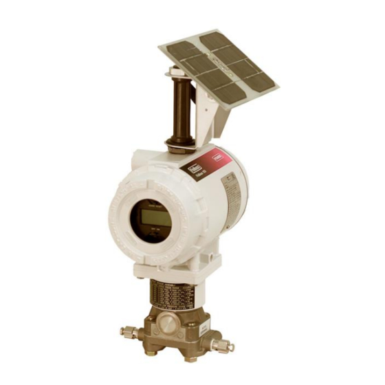
FloBoss 103/104 Instruction Manual Field conduit entry Optional solar panel mounts here Liquid crystal display (LCD) Dual variable sensor (DVS) Figure 1-1. FloBoss 103 Flow Manager with LCD Liquid crystal display (LCD) Pulse interface module Optional solar panel Pressure transducer Figure 1-2.
-
Page 11: Hardware
FloBoss 103/104 Instruction Manual The enclosure is fabricated from die-cast aluminum alloy with iridite plating and paint. The NEMA 4 enclosure protects the electronics from physical damage and harsh environments. The caps at either end of the enclosure unscrew to allow field maintenance. Two ¾-14 pipe-threaded holes permit field conduit wiring and communications.
-
Page 12
FloBoss 103/104 Instruction Manual Termination Located in the terminal side of the explosion-proof housing, the Module termination module provides connections to the field wiring. Refer to Figure 1-4. Local operator interface (LOI) COM2 Power supply I/O field wiring LOI (COM1) Figure 1-4. -
Page 13: Termination Board
FloBoss 103/104 Instruction Manual Display (LCD) drivers; and controls for the Dual-Variable Sensor (DVS), the Pulse Interface module, and the optional I/O termination points. The microprocessor has low-power operating modes, including inactivity and low battery condition. The FB100 comes standard with 512 KB of built-in, static random access memory (SRAM) for storing data and history.
-
Page 14: Firmware
FloBoss 103/104 Instruction Manual (DVS) or a Pulse Interface module. Three diagnostic analog inputs (AI) monitor the battery voltage, logical voltage, and enclosure/battery temperature. Refer to Chapter 4, Input/Output. Communications The Local Operator Interface (LOI) port provides a direct, local link between the FB100-Series and a PC through a Local Operator Interface cable using EIA-232 (RS-232) communications.
-
Page 15: Options And Accessories
FloBoss 103/104 Instruction Manual ▪ Alarm call-in to host for Spontaneous-Report-By-Exception (SRBX) ▪ User-level security. 1.2.4 Options and Accessories The FB100 supports the following options and accessories: ▪ Communication modules for either EIA-232 (RS-232), EIA-485 (RS-485), dial-up modem ▪ 6 Input/Output (I/O) termination points ▪…
-
Page 16: Fcc Information
FloBoss 103/104 Instruction Manual 1.2.5 FCC Information This equipment complies with Part 68 of the FCC rules. Etched on the modem assembly is, among other information, the FCC certification number and Ringer Equivalence Number (REN) for this equipment. If requested, this information must be provided to the telephone company.
-
Page 17: Flow Measurement
FloBoss 103/104 Instruction Manual 1.3.1 Flow Measurement The primary function of the FB100-Series is to measure the flow of natural gas through an orifice or turbine or rotary meter in accordance with the 1992 American Petroleum Institute (API) and American Gas Association (AGA) standards.
-
Page 18: History Points
FloBoss 103/104 Instruction Manual Accumulation energy over the calculation period. The flow and energy are then accumulated and stored at the top of every hour. At the configured contract hour, the flow and energy are then stored to the Daily Historical Log and zeroed for the start of a new day (contract hour).
-
Page 19: Hourly Historical Log
FloBoss 103/104 Instruction Manual IMV (Integral Multiplier Value) for AGA3 (Average) or BMV (Base Multiplier Value) for AGA7 (Average). Pressure Extension for AGA3 (Average) or Today’s Total for AGA7 (Totalize). Instantaneous Flow (Accumulate). Instantaneous Energy (Accumulate). History Point 2 (AGA3), History Point 3, History Point 4, and History…
-
Page 20
FloBoss 103/104 Instruction Manual Extended History The FB100 has configurable archive times (1 minute to 60 minutes) which, in turn, determine the number of entries. Alarm Log The Alarm Log contains the change in the state of any alarm signal that has been enabled for alarms. -
Page 21: Security
FloBoss 103/104 Instruction Manual temperature, pressure, Reynolds number, and warnings for orifice diameter, pipe diameter, and beta ratio. 1.3.3 Security The FB100 provides for security within the unit. A maximum of 16 log- on identifiers (IDs) may be stored. In order for the unit to communicate, the log-on ID supplied to ROCLINK 800 software must match one of the IDs stored in the FB100.
-
Page 22: Pass Through Communications
FloBoss 103/104 Instruction Manual 1.3.7 Pass Through Communications Pass Through Communications allow you to configure an FB100 unit to send Pass Through messages, when using a FB100. By using any of the FB100 communications ports, Pass Through Mode allows data to be received by one unit and then passed through to other devices connected on any other communications port.
-
Page 23: Processor And Memory
FloBoss 103/104 Instruction Manual ▪ EIA-485 (RS-485) communications (Comm 1) terminations ▪ RTD input terminations ▪ Optional I/O and terminations ▪ Remote charge terminations ▪ Optional Comm 2 terminations 1.4.2 Processor and Memory The FB100-Series derives processing power from a 32-bit microprocessor.
-
Page 24
FloBoss 103/104 Instruction Manual Local Operator Interface The Local Operator Interface (LOI) port provides direct (LOI) Port communications between the FB100 and the serial port of an operator interface device, such as personal computer using an EIA-232 (RS-232) link. The interface allows you to access the FB100 (using ROCLINK 800 software) for configuration and transfer of stored data. -
Page 25: Rtd Input
FloBoss 103/104 Instruction Manual The Comm 2 port is capable of initiating a message in support of Spontaneous-Report-by-Exception (SRBX) alarming. Refer to Chapter 3 for additional information. One of the following card types can be accommodated: ▪ EIA-232 (RS-232) for asynchronous serial communications (baud rate up to 19,200).
-
Page 26: Low Power Mode
If the battery voltage drops below 5.4 volts, the FB100 automatically shuts down. The FloBoss 103 monitors its orifice-metering Dual-Variable Sensor for accurate and continuous operation. The FloBoss 104 monitors its Pulse Interface Module.
-
Page 27: Additional Technical Information
FloBoss 103/104 Instruction Manual 1.5 Additional Technical Information Refer to Table 1-1 for additional and most-current technical documents (available at www.EmersonProcess.com/Remote). Table 1-1. Additional Technical Information Name Form Number Part Number FloBoss™ 103 Flow Manager FB103 D301152X012 FloBoss™ 104 Flow Manager…
-
Page 28
FloBoss 103/104 Instruction Manual [This page is intentionally left blank.] 1-22 General Information Revised August-2017… -
Page 29: Chapter 2 — Installation And Use
2.2.3 Compliance with Hazardous Area Standards …… 2-3 Mounting ………………2-4 2.3.1 General Guidelines …………… 2-4 2.3.2 Pipe Stand Mounting (FloBoss 103) ……..2-7 2.3.3 Orifice Plate Mounting (FloBoss 103) ……..2-7 2.3.4 Meter Mounting (FloBoss 104) ……….2-8 Startup and Operation …………..2-11 2.4.1 Starting the FB100 ………….
-
Page 30: Installation Requirements
FloBoss 103/104 Instruction Manual Place the meter run in service and monitor with ROCLINK 800 software for proper operation. 2.2 Installation Requirements Careful planning helps to ensure a smooth installation. Be sure to consider location, ground conditions, climate, and site accessibility, as well as the suitability of the FB100-Series application while planning an installation.
-
Page 31: Site Requirements
FloBoss 103/104 Instruction Manual 2.2.2 Site Requirements Careful consideration in locating the FB100 on the site can help prevent future operational problems. Consider the following when choosing a location: ▪ Local, state, and federal codes often place restrictions on monitoring locations and dictate site requirements.
-
Page 32: Mounting
You can mount the FB103 either of two ways: ▪ On a pipe stand: The FloBoss 103 can mount to a 2-inch pipe stand. Ensure that the pipe stand meets all weight requirements and installation conforms to local building codes.
-
Page 33: Processor Connections
FloBoss 103/104 Instruction Manual ▪ On an orifice plate: Directly mount to an orifice plate via a 3- or 5-valve manifold. With either mounting method, the pressure inputs must be piped to the process connections on the DVS. For more information on process connections, refer to Chapter 6.
-
Page 34
FloBoss 103/104 Instruction Manual Figure 2-2. Dimensions of FB104 Figure 2-3. Dimensions with 2-watt Solar Panel and LCD Installation and Use Revised August-2017… -
Page 35: Pipe Stand Mounting (Floboss 103/Floboss 104)
FloBoss 103/104 Instruction Manual 2.3.2 Pipe Stand Mounting (FloBoss 103/FloBoss 104) To install the FloBoss 103/ FloBoss 104 on a 2-inch pipe stand: Install the pipe stand per the directions included with the pipe stand. Remove the orifice/meter run from service.
-
Page 36: Meter Mounting (Floboss 104)
FloBoss 103/104 Instruction Manual Figure 2-5. FB104 Mounting Option for ATEX unit 2.3.4 Meter Mounting (FloBoss 104) The factory installs the Pulse Interface module to the base of the FB104. Do not remove the FB104 from the Pulse Interface module; you may damage cable connections between the interface and the FB100-Series backplane.
-
Page 37: Mounting Pulse Interface Module To Meter Housing
FloBoss 103/104 Instruction Manual Pulse Interface Module Meter Adapter Dowel pins extend 1.25 in min. Meter housing User-supplied 5/16-18 cap screws Shaft adapter 0.68 – 0.71 in Figure 2-6. Mounting Pulse Interface Module to Meter Housing on non-ATEX FB104 Rotary Meter…
-
Page 38: Magnet Installed On Long Shaft Adaptor
FloBoss 103/104 Instruction Manual Thread the magnet assembly on to the shaft adaptor until the top of the magnet is between 0.68–0.71 inches above the meter housing (refer to Figure 2-6). The magnet set-screw should be positioned over a flat in the hex shaft adaptor. Tighten the set-screw to lock the magnet assembly in place.
-
Page 39: Startup And Operation
FloBoss 103/104 Instruction Manual Remove the two dowel pins. In their place, install two 5/16-18 x 7/8 long bolts and lock washers. Securely tighten all cap screws attaching the FB104 to the meter. Once you install the Pulse Interface module to the meter, the pressure transducers are attached to the process.
-
Page 40: Operation
FloBoss 103/104 Instruction Manual – ON/OFF power jumper NORM RESET jumper Figure 2-9. On/Off Power Jumper (FB103 with Optional LCD) Reattach the top-end cap cover (LCD end). Screw the cover on until metal contacts metal. Do not over-tighten the cover.
-
Page 41: Configuration
FloBoss 103/104 Instruction Manual procedures in a hazardous area could result in personal injury or property damage. During operation, you can monitor the FB100 (to view or retrieve current and historical data) either locally or remotely. Accomplish local monitoring either by viewing the LCD panel or by using ROCLINK 800 software on a PC connected through the LOI port.
-
Page 42
FloBoss 103/104 Instruction Manual [This page is intentionally left blank.] 2-14 Installation and Use Revised August-2017… -
Page 43: Chapter 3 — Power Connections
The FB100 accepts input voltages from 8.0 volts to 28 volts at the charge (CHG+ / CHG-) terminals on the termination board. Note The maximum power usage for DC voltage sources is 130 mW for the FloBoss 103 and 300 mW for the FloBoss 104, excluding battery charging. Revised August-2017 Power Connections…
-
Page 44: Grounding Installation Requirements
FloBoss 103/104 Instruction Manual Do not allow the batteries to fully discharge. Either keep providing input Caution power or turn the device off. If the batteries fully discharge, the battery charger board may enter thermal limiting, which prevents the batteries from overheating but restricts input power.
-
Page 45: Installing Grounding For The Fb100
FloBoss 103/104 Instruction Manual 3.2.2 Installing Grounding for the FB100 The FB100 unit has two grounding screws inside the enclosure and one grounding screw outside the enclosure. For the grounding screw locations, refer to Figure 3-1. The grounding installation method for the FloBoss 100-Series depends on whether the pipeline has cathodic protection.
-
Page 46: Determining Power Requirements
(in mW) of any other devices used with the FB100 in the same power system. The maximum power for DC voltage sources is 130 mW for the FloBoss 103 and 300 mW for the FloBoss 104, not including the battery charging.
-
Page 47: Sizing The Solar Panel
FloBoss 103/104 Instruction Manual Solar arrays generate electrical power for the FB100 from solar radiation. The size of solar panels required for a particular installation depends on several factors, including the power consumption of all devices connected to the solar array and the geographic location of the installation.
-
Page 48: Batteries
FloBoss 103/104 Instruction Manual Notes: ▪ The “I panel” value varies depending on the type of solar panel installed. Refer to the vendor’s specifications for the solar panel being used. ▪ The FB100 can accept a maximum of about 1 Amp, limited by its charging circuit.
-
Page 49: Determining Battery Requirements
FloBoss 103/104 Instruction Manual In these circumstances, remove the battery charger module (part W38231X0032) and use the FB103 or FB104 without internal power batteries. Refer to Section 3.5.3, Replacing the Batteries, for instructions on removing the battery charger module or contact Remote Automation Solutions LifeCycle Services for assistance in removing the battery charger module.
-
Page 50: Wiring Connections
FloBoss 103/104 Instruction Manual 3.6 Wiring Connections The following paragraphs describe how to connect the FB100 to power, I/O devices, and communications devices. Use the recommendations and procedures described in the following paragraphs to avoid damage to equipment. : Check the input power polarity before turning on the power.
-
Page 51: Connecting Main Power Wiring
(CHG+ / CHG-) with no external current limiting (internal current limit is 200 mA). The maximum power for DC voltage sources is 130 mWatts for the FloBoss 103 and 300 mWatts for the FloBoss 104, not including battery charging.
-
Page 52: Backing Up Configuration And Log Data
FloBoss 103/104 Instruction Manual It is important to use good wiring practices when sizing, routing, and connecting power wiring. Ensure that all wiring conforms to state, local, and NEC codes. The CHG+ / CHG- terminal can accommodate up to 16 AWG wire.
-
Page 53: Chapter 4 — Input/Output
FloBoss 103/104 Instruction Manual Chapter 4 – Input/Output In This Chapter I/O Description …………….. 4-1 4.1.1 Selecting the Type of I/O …………4-2 I/O Wiring Requirements …………..4-3 Analog Input ………………4-3 4.3.1 Wiring the Analog Input …………4-3 Analog Output ……………… 4-4 4.4.1 Wiring the Analog Output (6-point I/O Board) ……
-
Page 54: Selecting The Type Of I/O
FloBoss 103/104 Instruction Manual 4.1.1 Selecting the Type of I/O To select the type of output for the Analog Output/Discrete Output #1 channel, flip the AO/DO switch on the termination board to the desired position. Refer to Figure 4-1 for the switch location. Then select the desired output type on the Configure >…
-
Page 55: I/O Wiring Requirements
FloBoss 103/104 Instruction Manual 4.2 I/O Wiring Requirements I/O wiring requirements are site and application dependent. Local, state, or NEC requirements determine the I/O wiring installation methods. Direct burial cable, conduit and cable, or overhead cables are options for I/O wiring installations.
-
Page 56: Analog Output
FloBoss 103/104 Instruction Manual Figure 4-2. Analog Input Wiring 4.4 Analog Output The Analog Output (AO) on the 6-point I/O termination board provides a 4–20 mA current source. The analog outputs use a 12-bit D/A converter with A/D values of 0 and 4095.
-
Page 57: Wiring The Analog Output (4-Point I/O Board)
FloBoss 103/104 Instruction Manual 4.4.2 Wiring the Analog Output (4-point I/O Board) Figure 4-4 shows the analog output wired as a current source, where AO+ Positive Current control Common Control 1-5V output 4-20mA current device – External power – Figure 4-4. 4–20 mA Analog Output Current Control…
-
Page 58: Wiring The Discrete Input
FloBoss 103/104 Instruction Manual : The selectable analog inputs/discrete input channels should have Note the 250-ohm resistor disabled when configured for use as discrete inputs. 4.5.1 Wiring the Discrete Input Figure 4-6 shows the terminals for connecting the DI wiring. The “+”…
-
Page 59: Wiring The Discrete Output
FloBoss 103/104 Instruction Manual ▪ Toggle mode. ▪ Latched mode. ▪ Timed discrete output (TDO) mode. : The switch for the selectable Analog Output/Discrete Output Note (DO-1) should be in the DO position, when configured for use as a Discrete Output.
-
Page 60: Rtd Input
FloBoss 103/104 Instruction Manual Figure 4-8. Pulse Input Wiring 4.8 RTD Input The temperature is input through the Resistance Temperature Detector (RTD) probe and circuitry. The RTD temperature probe mounts directly to the piping using a thermowell, outside the FloBoss enclosure. The RTD probe is then wired to the FloBoss RTD connections.
-
Page 61: Chapter 5 — Communications
FloBoss 103/104 Instruction Manual Chapter 5 – Communications In This Chapter Communications Overview ………….. 5-1 EIA-485 (RS-485) Communications Wiring ……..5-2 Local Operator Interface Port Wiring ……….5-2 Serial Communications Card …………5-3 Dial-up Modem Communications Card ……….5-4 This chapter describes the communications ports and cards available for FB100.
-
Page 62: Rs-485) Communications Wiring
FloBoss 103/104 Instruction Manual LOI port Comm 2 port Comm 1 port Figure 5-1. Communication Port Locations on Termination Board 5.2 EIA-485 (RS-485) Communications Wiring The EIA-485 communication accommodates RS-485 and EIA-485 signals on the Comm 1 port located on the termination board.
-
Page 63: Serial Communications Card
FloBoss 103/104 Instruction Manual ® Windows operating system. A prefabricated operator interface cable is available as an accessory. Refer to Figure 5-2. The LOI port is intended for use with a PC running ROCLINK 800 software. This LOI port is compatible with EIA-232 (RS-232) levels.
-
Page 64: Dial-Up Modem Communications Card
FloBoss 103/104 Instruction Manual Table 5-2. Communications Card Signals Signals Action The request to send signals that the modem is ready to transmit. The RXD receive data signals that data is being received at the communications card. The TXD transmit data signals that data is being transmitted from the communications card.
-
Page 65
FloBoss 103/104 Instruction Manual Delay, and 10 millisecond Key Off Delay. On power up, the modem must be set up for Auto Answer. Periodic checks are made to ensure that the modem is still in Auto Answer or that it is not left off the hook after a certain period of non-communication. -
Page 66
FloBoss 103/104 Instruction Manual [This page is intentionally left blank.] Communications Revised August-2017… -
Page 67: Chapter 6 — Dual-Variable Sensor (Dvs)
FloBoss 103/104 Instruction Manual Chapter 6 – Dual-Variable Sensor (DVS) In This Chapter Dual-Variable Sensor …………… 6-1 6.1.1 Making Process Connections ……….6-2 6.1.2 Configuring the DVS …………. 6-2 This chapter describes the Dual-Variable Sensor (DVS), which provides differential pressure and static pressure inputs to the FB103 for orifice flow calculation.
-
Page 68: Making Process Connections
FloBoss 103/104 Instruction Manual : Consult your local sales representative for special ranges. Note 6.1.1 Making Process Connections Piping from the meter run connects to the DVS. Both the static and differential pressure sensors connect to female ¼-18 NPT connections on the bottom of the DVS.
-
Page 69
FloBoss 103/104 Instruction Manual pressure, RTD, and enclosure/battery temperature, to the selected metric mode. : When you select metric mode, realize that the FB103 adjusts Note only the Units. You must manually change all values to the proper unit of measurement. -
Page 70
FloBoss 103/104 Instruction Manual [This page is intentionally left blank.] Dual-Variable Sensor Revised August-2017… -
Page 71: Chapter 7 — Pulse Interface Module
FloBoss 103/104 Instruction Manual Chapter 7 – Pulse Interface Module In This Chapter Pulse Interface Module …………..7-1 7.1.1 Making Process Connections ……….7-3 7.1.2 Configuring the Pulse Interface Module ……. 7-3 This chapter describes the Pulse Interface module, which provides pressure inputs and pulses counts to the FloBoss 104 for AGA7 flow calculation with AGA8 compressibility.
-
Page 72: Static Pressure
FloBoss 103/104 Instruction Manual • Static pressure is sampled once per second. • Temperature is sampled and linearized once per second. Pressure transducer Pulse Interface module Meter adaptor Figure 7-1. FloBoss 104 Assembly The FB104 implements standard PI and AI alarming along with sensor and flow alarms.
-
Page 73: Making Process Connections
FloBoss 103/104 Instruction Manual The pressure transducers provide the measurement of the line pressure (P1) and can optionally measure downstream pressure or station inlet pressure (aux P2). The Pulse Interface module is attached to the base of the FB104 at the factory.
-
Page 74
FloBoss 103/104 Instruction Manual [This page is intentionally left blank.] Pulse Interface Module Revised August-2017… -
Page 75: Chapter 8 — Calibration
FloBoss 103/104 Instruction Manual Chapter 8 – Calibration In This Chapter Calibration (AI, RTD & Meter) …………8-1 Performing a Calibration …………..8-1 Adjusting for Zero Shift …………..8-7 Verifying a Calibration …………..8-8 This chapter describes the processes for calibrating the AI, RTD, and Meter modules for the FB100-Series devices.
-
Page 76
Value. The FB100 uses these values in the flow calculations while calibrating the points. Click Freeze. Figure 8-1. Meter Calibration (FloBoss 103 Shown) If you are calibrating a pressure input, read the following Caution, and then isolate the pressure sensors from the process. -
Page 77: Pressure Calibration Open/Close Orientation
FloBoss 103/104 Instruction Manual Bleed Bleed High Pressure Open Remains Close Close Operating Shutdown Sequence Shutdn2 Figure 8-2. Removing the DVS from Service If you are calibrating a pressure input, set up the pressure calibrator and make the necessary connections to the DVS. Refer to Figure 8-3 for the line orientation during the calibration.
-
Page 78: Set Zero Calibration
FloBoss 103/104 Instruction Manual Figure 8-4. Set Zero Calibration Example Apply the low (zero) value. For a pressure input, this would typically be open to atmosphere. Enter the applied value in the Dead Weight / Tester Value field of the Set Zero dialog. Refer to Figure 8-4. For static pressure on an absolute-pressure device, remember to enter the actual current atmospheric pressure, such as 14.73 psi.
-
Page 79
FloBoss 103/104 Instruction Manual Figure 8-6. Set Midpoint 1 If you are performing a two-point calibration, click Done. Calibration for this input is complete. To calibrate midpoints, apply the desired pressure or temperature and enter the applied value in the Dead Weight / Tester Value field. -
Page 80
FloBoss 103/104 Instruction Manual If you are performing a four-point calibration, click Done. Calibration for this input is complete. To calibrate a third midpoint, apply the desired pressure or temperature and enter the applied value in the Dead Weight / Tester Value field. -
Page 81: Adjusting For Zero Shift
FloBoss 103/104 Instruction Manual 8.3 Adjusting for Zero Shift If desired, use the zero shift procedure after calibrating the differential pressure input for the FB103. The FB103 calibrates differential pressure without applying line pressure to the sensor. When you connect the sensor back to the process after calibration, a shift in the differential pressure can occur due to the influence of the line pressure.
-
Page 82: Verifying A Calibration
FloBoss 103/104 Instruction Manual 8.4 Verifying a Calibration ROCLINK 800 software can verify the calibration to check if the DVS requires re-calibration. To verify the calibration: Start ROCLINK 800 software and connect to the FB100. Select Meter > Calibration. Click Freeze. The Meter Calibration window displays. The current reading displays under each meter input as the Freeze Value.
-
Page 83
FloBoss 103/104 Instruction Manual Figure 8-12. Verify Calibration To log the Tester Value and the Live Reading to the Event Log as a record of the verification, click Log Verify. Click Done. The Meter Calibration screen displays. Continue to verify all required pressures/values. -
Page 84
FloBoss 103/104 Instruction Manual [This page is intentionally left blank.] 8-10 Calibration Revised August-2017… -
Page 85: Chapter 9 — Troubleshooting
FloBoss 103/104 Instruction Manual Chapter 9 – Troubleshooting In This Chapter Troubleshooting Guidelines …………. 9-1 Troubleshooting Checklists ………….. 9-2 9.2.1 Dial-up Modem …………..9-2 9.2.2 Serial Communications …………9-2 9.2.3 Optional I/O …………….9-2 9.2.4 Software Issues …………..9-3 9.2.5 Power Issues ……………. 9-3 9.2.6 Dual-Variable Sensor (FB103) ……….
-
Page 86: Troubleshooting Checklists
FloBoss 103/104 Instruction Manual Troubleshooting Checklists 9.2.1 Dial-up Modem If you are experiencing troubles with an internal dial-up modem: ▪ Check to make sure you’ve applied power to the FB100. Check the ON/OFF jumper, the wiring connections at CHG+ and CHG-, and the wiring at the power source.
-
Page 87: Software Issues
FloBoss 103/104 Instruction Manual : No field repair or replacement parts are associated with the Note I/O termination points. 9.2.4 Software Issues If you are experiencing problems with the FB100 that appear to be software-related, try resetting the FB100. ▪ Use a warm start to restart without losing configuration or log data.
-
Page 88: Pulse Interface Module (Fb104)
FloBoss 103/104 Instruction Manual If the input shows a Point Fail alarm, then the sensor is not communicating with the FB100. The DVS contains no user-serviceable or user-replaceable parts. Return the FB100 to your local sales representative for repair or replacement.
-
Page 89: Procedures
FloBoss 103/104 Instruction Manual 9.3 Procedures 9.3.1 Preserving Configuration and Log Data Perform this backup procedure before your remove power from the FB100 for repairs, troubleshooting, removing or adding components, or upgrades. This procedure preserves the current flow computer configuration and log data held in RAM.
-
Page 90: Restarting And Reconfiguring
FloBoss 103/104 Instruction Manual : This cold start does not include any of the clearing options Note available in a cold start you perform using ROCLINK 800. Unscrew the front end cap cover (LCD end). Place the reset jumper (located on the LCD, if installed, or on the Battery Charger board at J2) in the RST position.
-
Page 91: Connecting The Termination Board To The Backplane
Click Download to restore the configuration. 9.3.4 Connecting the Termination Board to the Backplane Older FloBoss 103 units were shipped with the termination board connected to the backplane through a 34-pin interface connector. Your FB103 may have a shrouded connector which ensures the correct polarity.
-
Page 92
FloBoss 103/104 Instruction Manual Attach this end to backplane first. Attach this end to termination board second Figure 9-2 . 34-Pin Interface Connector Troubleshooting Revised August-2017… -
Page 93: Appendix A — Glossary
FloBoss 103/104 Instruction Manual Appendix A – Glossary Note: This is a generalized glossary of terms. Not all the terms may necessarily correspond to the particular device or software described in this manual. For that reason, the term “ROC” is used to identify all varieties of Remote Operations Controllers (including ROC800-Series, ROC800L, DL8000, FloBoss™…
-
Page 94
FloBoss 103/104 Instruction Manual Communications port on a personal computer (PC). (continued) COMM Communications port on a ROC used for host communications. . Note: On FloBoss 500-Series and FloBoss 407s, COMM1 is built-in for RS-232 serial communications. Comm Module Module that plugs into a ROC to provide a channel for communications via a specified communications protocol, such as EIA-422 (RS-422) or HART. -
Page 95: Flash Rom
FloBoss 103/104 Instruction Manual Distributed RTU Network, in which two or more remotely distributed RTU devices (RRTUs) are wirelessly connected in a peer-to-peer network to share data. (continued) DRTU A primary component of the Distributed RTU Network, consisting of a FB107 chassis housing a focused functionality CPU and a Network Radio module (NRM).
-
Page 96: Integral Multiplier Value
(www.fieldbus.org). Compressibility Factor. (continued) Frequency Shift Keypad. Function Sequence Table, a type of user-written program in a high-level language designed by Emerson Process Management’s Flow Computer Division. Foot or feet. Ground Fault Analysis. Gigahertz, 10 cycles per second Electrical ground, such as used by the ROC’s power supply.
-
Page 97: Integral Value
FloBoss 103/104 Instruction Manual Integral Value. Kilobytes. KiloHertz. Liquid Crystal Display. Local Display Panel, a display-only device that plugs into ROC300-Series units (via a parallel interface cable) used to access information stored in the ROC. Light-Emitting Diode. Logical Number The point number the ROC and ROC Plus protocols use for I/O point types are based on a physical input or output with a terminal location;…
-
Page 98
FloBoss 103/104 Instruction Manual (continued) Node A basic structural component of the Distributed RTU Network. A node (usually a FB107 chassis housing a focused-functionality CPU and a Network Radio module) provides a data collection point that wirelessly transmits data throughout the designed network. -
Page 99: Built-In
FloBoss 103/104 Instruction Manual Protocol A set of standards that enables communication or file transfers between two computers. Protocol parameters include baud rate, parity, data bits, stop bit, and the type of duplex. PSTN Public Switched Telephone Network. Process Temperature.
-
Page 100: Static Random Access Memory
FloBoss 103/104 Instruction Manual (continued) Script An uncompiled text file (such as keystrokes for a macro) that a program interprets in order to perform certain functions. Typically, the end user can easily create or edit scripts to customize the software.
-
Page 101
Communication Ports ……..1-17 FCC Information ……….1-10 Communications Figures Wiring …………. 5-1 1-1. FloBoss 103 Flow Manager with LCD ..1-4 Communications Cards 1-2. FloBoss 104 Flow Manager ….1-4 Descriptions ………… 5-1 1-3. Inside the FB100-Series Enclosure ..1-5 Dial-Up Modem………. -
Page 102
FloBoss 103/104 Instruction Manual 2-1. FB103 Dimensions (without a Solar Panel) Flow Time …………1-11 …………..2-5 Flowing Minutes ……….1-12 2-2. FB104 Dimensions ……..2-6 Function Sequence Tables ……. 1-15 2-3. FloBoss Dimensions (with a 2-watt Functions …………1-10 Solar Panel and LCD) ……..2-6 2-4. -
Page 103
FloBoss 103/104 Instruction Manual RAM …………..1-7 RBX Function ………… 1-15 Memory …………. 1-17 Real-Time Clock ……….1-19 Metric …………..6-2 Related technical information ……1-21 Microprocessor ………. 1-7, 1-17 Removing power ……….9-6 Min / Max Historical Log ……..1-13 Repair ………….. -
Page 104
FloBoss 103/104 Instruction Manual Discrete Outputs ……….4-6 EIA-485 Communications Cards ….5-2 Vibration ……………2-2 General …………3-8 Voltage …………..3-4 Grounding …………3-8 Grounding Requirements ……. 3-2 I/O Card Pulse Inputs ……..4-7 I/O Wiring …………4-3 Watchdog LOI …………..5-3 Software and Hardware…….. -
Page 105
FloBoss 103/104 Instruction Manual [This page is intentionally left blank.] Revised August-2017… -
Page 106
Emerson Automation Solutions Remote Automation Solutions Emerson FZE P.O. Box 17033 © 2002–2017 Remote Automation Solutions, a business unit of Emerson Automation Jebel Ali Free Zone – South 2 Solutions. All rights reserved. Dubai U.A.E. This publication is for informational purposes only. While every effort has been made to ensure…
Table of Contents for Emerson FloBoss 103:
-
安全使用指南 – FloBoss 103 第 2 页 文档 A6150 规格 电源 外部电源充电输入:8-28 V dc,反接保护。 输入电流:5 mA 标称。100% 占空比时为 9.5 mA。 外包装 外壳和顶盖:带浸镀铬电镀和油漆的压铸铝合金。 提供熔模铸造不锈钢 (CF8M) 版本。 环境 工作环境温度:-40 至 75°C。 LCD 显示器:-20 至 75°C。 存储温度:-50 至 85°C。 工作湿度:5% 至 95%,非冷凝。 重量 6.58 kg(铝);12.1 kg (SST)。 DVS 传感器(可选) 差压输入
-
Инструкции по безопасной эксплуатации – FloBoss 103 Страница 4 Форма A6150 Рис 3. Задняя часть контроллера FloBoss 103 (с платой разъемов) Надлежащее заземление контроллера FloBoss 103 позволяет уменьшить влияние электрических помех на
-
Consignes de sécurité — FloBoss 103 Page 4 Formulaire A6150 Dénuder le moins possible les fils du débitmètre, pour éviter l’exposition de ces parties dénudées et éviter les courts-circuits. Lors des raccordements, prévoir une longueur suffisante pour prévenir toute tension du fil. Le FloBoss 103 accepte des tensions d’entrée de 8 à 28 volts au niveau des bornes de charge (CHG+ / CHG-), sans limitation de courant extern
-
Safe Use Instructions – FloBoss 103 Page 6 Emerson Process Management Remote Automation Solutions Marshalltown, IA 50158 U.S.A. Houston, TX 77065 U.S.A. Pickering, North Yorkshire UK Y018 7JA © 2003-2008 Remote Automation Solutions, division of Emerson Process Management. All Rights Reserved. Form A6150 Figure 8. FloBoss 103 Dimensions Figure 9. FloBoss 103 Mounting Styles Bristol, Inc., Bristol Babcock Ltd, Bristol Canada, BBI SA de CV and the Flow Com
-
Pokyny pro bezpečné použití – jednotka FloBoss 103 Stránka 5 Formulář A6150 Výchozí hodnoty všech parametrů jsou uloženy ve firmwaru jednotky FloBoss. Pokud je výchozí hodnota pro danou aplikaci přijatelná, lze ji ponechat beze změny. Nastavení jednotky FloBoss se provádí prostřednictvím konfiguračního softwaru. Pokyny jsou uvedeny v Uživatelské příručce konfiguračního softwaru ROCLINK 800 (Formulář A6121). 8. Postupy kalibrace podporují 5bodo
-
Safe Use Instructions — FloBoss 103 Page 3 Form A6150 Orifice Plate mounted to an orifice plate via a 3- or 5-valve manifold. See Figure 9. At the factory, the Dual-Variable Sensor’s connector is mounted to a coupler, which is mounted directly on a flat flange to the FloBoss enclosure with a 4- bolt pattern. The optional blank plate is available when the FloBoss 103 is ordered without a DVS sensor. At the factory, the blank plate is mounted directly on a flat flange to the FloBoss enclosure with a 4-bolt pattern. Th
-
Pokyny pro bezpečné použití – jednotka FloBoss 103 Stránka 6 Emerson Process Management Remote Automation Solutions Marshalltown, IA 50158 U.S.A. Houston, TX 77065 U.S.A. Pickering, North Yorkshire UK Y018 7JA © 2003-2008 Remote Automation Solutions, divize společnosti Emerson Process Management. Všechna práva vyhrazena. Formulář A6150 Obrázek 8. Rozměry jednotky FloBoss 103 Obrázek 9. Způsoby upevn�
-
Safe Use Instructions November 2008 Remote Automation Solutions www.EmersonProcess.com/Remote Form A6150 FloBoss TM 103 Flow Manager UK Safe Use Instructions ES Instrucciones de seguridad para de uso FR Consignes de sécurité NL Instructies voor veilig gebruiks PT Instruções para uso seguro CZ Pokyny pro bezpečné použití RU Инструкции по безопасной эксплуатации SC 安全使用指示
-
Instrucciones de seguridad para el uso de FloBoss 103 Página 5 Formulario A6150 Figura 7. Extremo frontal de FloBoss 103 (sin LCD) 7. La unidad FloBoss 103 debe configurarse antes de calibrarse y ponerse en funcionamiento. La configuración debe realizarse por medio del software ROCLINK 800 en una computadora personal compatible con IBM. La computadora personal por lo general se conecta al puerto de LOI de la computadora de fl
Questions, Opinions and Exploitation Impressions:
You can ask a question, express your opinion or share our experience of Emerson FloBoss 103 device using right now.
Инструкции по безопасной эксплуатации – FloBoss 103
7. Перед калибровкой и вводом в эксплуатацию
FloBoss 103 его необходимо сконфигурировать.
Конфигурирование должно быть выполнено с
помощью программного обеспечения ROCLINK
800, установленного на IBM-совместимом
персональном компьютере. Персональный
компьютер обычно подключается к порту LOI
контроллера расхода для передачи данных
конфигурации в контроллер FloBoss 103, хотя
можно выполнить конфигурирование в
автономном режиме и затем загрузить
конфигурацию в контроллер.
Значения по умолчанию всех параметров
находятся в микропрограммном обеспечении
контроллера FloBoss. Если значение по
умолчанию подходит для конкретного варианта
применения устройства, его можно не изменять.
Выполните необходимые настройки контроллера
FloBoss с помощью конфигурационного
программного обеспечения. См. Руководство
пользователя конфигурационного
программного обеспечения ROCLINK 800
(Форма A6121).
8. Процедуры калибровки поддерживают
5-точечную калибровку с калибровкой трех
средних точек в любом порядке. Сначала
выполните калибровку малых или нулевых,
а затем больших или предельных показаний.
После этого можно откалибровать три средних
точки, если требуется. Калибровка
диагностических аналоговых
входов — логическое напряжение (E1),
напряжение батареи (E2) и температура
платы/батареи (E5) — не предусмотрена.
Если установлены дополнительные точки
подключения входов/выходов (I/O), аналоговый
вход можно откалибровать с помощью
программного обеспечения ROCLINK 800.
Ниже перечислены встроенные входы, для
которых поддерживается 5-точечная калибровка:
вход перепада давления, расположенный в
точке аналогового входа A1;
вход статического давления, расположенный в
точке аналогового входа A2;
вход температуры RTD, расположенный в точке
аналогового входа A3.
Эти входы назначаются первым трем точкам
аналоговых входов. Процедура калибровки для
этих входов описана в Руководстве
пользователя конфигурационного
программного обеспечения (Форма A6121).
9. При поиске и устранении неполадок
контроллера FloBoss 103 следует определить, с
чем связана неполадка — с конфигурацией или с
аппаратными средствами. Проверьте
конфигурацию в программном обеспечении
ROCLINK 800, чтобы выявить любые
неправильные настройки. Проверьте аппаратные
средства на предмет повреждения. Проверьте
платы разъемов в отношении ошибок
расположения соединений.
При наличии неполадок в контроллере FloBoss
103, предположительно связанных с
программным обеспечением, попробуйте
перезапустить FloBoss путем «горячей»
перезагрузки, «холодной» перезагрузки или с
помощью перемычки.
При наличии неполадок, предположительно
связанных с аппаратными средствами,
проверьте проводку. Если неполадки
сохраняются, обратитесь в местное
представительство по продажам для получения
права на возврат.
Во время эксплуатации можно осуществлять
локальный или удаленный контроль работы
контроллера FloBoss 103 (просматривать или
получать текущие и архивные данные).
Локальный контроль выполняется либо путем
подробно описанного в разделе 2 наблюдения за
ЖК-панелью, либо с помощью программного
обеспечения ROCLINK 800, установленного на
ПК, подключенном к порту LOI. Удаленный
контроль осуществляется через порт Comm 1
или Comm 2 контроллера FloBoss с помощью
программного обеспечения ROCLINK 800 или
управляющей системы. В отношении соединений
связи обратитесь к Рис 4.
10. Для вывода FloBoss 103 из эксплуатации
выполните следующие действия. Отключите
питание блока и затем удалите все внешние
соединения. Удалите газопроводы. Наконец,
снимите корпус FloBoss с подставки
трубопровода или фильерной пластины.
Контроллер можно поместить в коробку для
транспортировки.
Форма A6150
Страница 6
Form A6114 Part Number D301153X012 October 2002 FLOBOSS™ 103 FLOW MANAGER Instruction Manual Flow Computer Division Website: www.EmersonProcess.com/flow FloBoss 103 Instruction Manual Revision Tracking Sheet October 2002 This manual is periodically to incorporate new or updated information. The date revision level of each page is indicated at the bottom of the page opposite the page number. A major change in the content of the manual also changes the date of the manual, which appears on the front cover. Listed below is the date revision level of each page. Page All Pages All Pages Revision 10/02 (applies to version 1.10) 04/02 (applies to version 1.0) FloBoss and ROCLINK are marks of one of the Emerson Process Management companies. The Emerson logo is a trademark and service mark of Emerson Electric Co. All other marks are the property of their respective owners. © Fisher Controls International, Inc. 2002. All rights reserved. Printed in the U.S.A. While this information is presented in good faith and believed to be accurate, Fisher Controls does not guarantee satisfactory results from reliance upon such information. Nothing contained herein is to be construed as a warranty or guarantee, express or implied, regarding the performance, merchantability, fitness or any other matter with respect to the products, nor as a recommendation to use any product or process in conflict with any patent. Fisher Controls reserves the right, without notice, to alter or improve the designs or specifications of the products described herein. ii Rev 10/02 FloBoss 103 Instruction Manual Table of Contents SECTION 1 – GENERAL INFORMATION............................................................ 1-1 1.1 1.2 1.3 1.4 1.5 1.6 1.7 Section Contents........................................................................................................................ 1-1 Manual Overview...................................................................................................................... 1-1 Additional Information.............................................................................................................. 1-1 Product Overview...................................................................................................................... 1-2 Product Functions...................................................................................................................... 1-8 Product Electronics ................................................................................................................. 1-13 FloBoss 103 Specifications ..................................................................................................... 1-18 SECTION 2 – USING THE FLOBOSS 103.............................................................. 2-1 2.1 2.2 2.3 2.4 2.5 2.6 2.7 2.8 2.9 Installation Requirements.......................................................................................................... 2-1 Mounting ................................................................................................................................... 2-5 Power Requirements ................................................................................................................. 2-8 Solar Powered Installations ....................................................................................................... 2-8 Connecting the FloBoss 103 to Wiring ................................................................................... 2-10 Startup and Operation.............................................................................................................. 2-14 Configuration .......................................................................................................................... 2-15 Calibration............................................................................................................................... 2-16 Troubleshooting and Repair .................................................................................................... 2-16 SECTION 3 – COMMUNICATION CARDS........................................................... 3-1 3.1 Serial Communications Card .................................................................................................... 3-1 3.2 Dial-up Modem Communications Card .................................................................................... 3-3 3.3 Communication Cards Specifications ....................................................................................... 3-4 SECTION 4 – DUAL-VARIABLE SENSOR............................................................ 4-1 4.1 4.2 4.3 4.4 4.5 4.6 Description ................................................................................................................................ 4-1 Process Connections.................................................................................................................. 4-2 Configuration ............................................................................................................................ 4-2 Calibration................................................................................................................................. 4-3 Troubleshooting ...................................................................................................................... 4-10 Specifications .......................................................................................................................... 4-11 SECTION 5 – INPUT/OUTPUT TERMINATION POINTS.................................. 5-1 5.1 5.2 5.3 5.4 5.5 5.6 Analog Input.............................................................................................................................. 5-1 Analog Output ........................................................................................................................... 5-3 Discrete Input ............................................................................................................................ 5-4 Discrete Output ......................................................................................................................... 5-5 Troubleshooting ........................................................................................................................ 5-5 I/O Termination Point Specifications........................................................................................ 5-6 Rev 10/02 Table of Contents iii FloBoss 103 Instruction Manual GLOSSARY OF TERMS ........................................................................................... G-1 INDEX ............................................................................................................................I-1 iv Table of Contents Rev 10/02 FloBoss 103 Instruction Manual SECTION 1 – GENERAL INFORMATION 1.1 Section Contents This section contains the following information: Section Page 1.2 Manual Overview 1-1 1.3 Additional Information 1-1 1.4 Product Overview 1-2 1.5 Product Functions 1-8 1.6 Product Electronics 1-13 1.7 FloBoss 103 Specifications 1-18 1.2 Manual Overview This manual describes the FloBoss™ 103 Flow Manager, part of the family of FloBoss flow computers manufactured by Emerson Process Management. This manual includes the following sections: Section 2 – Using the FloBoss 103 provides information concerning the use of the FloBoss including installation requirements, mounting the FloBoss 103, power requirements, the termination board, backplane board, battery charger board, Local Operating Interface (LOI), EIA-485 (RS-485) communications, wiring, processes, and troubleshooting. Section 3 – Communication Cards provide information and specifications for the optional EIA-232 (RS-232) and dial-up modem communication cards. Section 4 – Dual-Variable Sensor describes the Dual-Variable Sensor (DVS) included with the FloBoss 103 for sensing static pressure and differential pressure. Section 5 – I/O Termination Points describes the optional input/output termination points that provide additional inputs and outputs for implementing expanded monitoring and control applications. Glossary of Terms – defines terms used in documentation. Topical Index – alphabetically lists the items contained in this manual along with their page numbers. 1.3 Additional Information The following manuals include additional information not found in this manual: ROCLINK 800 Configuration Software User Manual – Form A6121 - Part Number D301159X12 Rev 10/02 General Information 1-1 FloBoss 103 Instruction Manual ROC/FloBoss Accessories Instruction Manual – Form A4637 - Part Number D301061X012 1.4 Product Overview The FloBoss 103 is a 32-bit microprocessor-based Electronic Flow Computer. The FloBoss 103 Flow Manager electronically measures, monitors, and manages gas flow for a single meter run using orifice plate (differential pressure) techniques. This economical flow computer reliably and accurately performs gas flow calculations, temperature measurements, data archival, and remote communications with an optional communications card installed. The FloBoss 103 performs minute, 10-minute, hourly (periodic), daily, and minimum / maximum historical data archrivals. The FloBoss 103 is the perfect solution to electronically replace traditional paper charting. The FloBoss records the corrected gas flow across an orifice plate, stores the data, and has the ability to send the data to a remote host. The FloBoss 103 computes gas flow for both volume and energy. The FloBoss provides on-site functionality and supports remote monitoring, measurement, data archival, communications, and control. The FloBoss design allows you to configure specific applications, including those requiring logic and sequencing control using a Function Sequence Table (FST). The FloBoss 103 provides the following components and features: i Weather-tight enclosure. i Termination Board. i 32-bit Processor Board. i Battery Charger Board. i Backplane Board. i 2 MB of flash ROM (Random Access Memory), which is field upgradeable. i 512K of battery backed-up RAM (Random Access Memory) storage. i Integral Dual-Variable Sensor (DVS) for static pressure and differential pressure measurement using orifice metering. i Support for a three-wire 100-ohm Resistance Thermal Detector (RTD) input. i Internal lead-acid batteries (optional). i Local Operator Interface (LOI) port – EIA-232 (RS-232). i EIA-485 (RS-485) Comm 1 port. i Communications card using EIA-232 (RS-232) or dial-up modem on Comm 2 port (optional). i Extensive applications firmware. Physically, the FloBoss 103 consists of a termination board with or without optional I/O points, RAM battery backup board, optional Comm 2 communications card, processor board, charger board, backplane board, and optional display housed in a compact, weather-tight case. The FloBoss is packaged in a NEMA 4 windowed enclosure that mounts on a pipestand or to an orifice plate via a three or five valve manifold. The aluminum enclosure protects the electronics from physical damage and harsh environments. Refer to Figure 1-1, Figure 1-2, and Figure 1-3. 1-2 General Information Rev 10/02 FloBoss 103 Instruction Manual The enclosure is fabricated from die-cast aluminum alloy with iridite plating and paint. The NEMA 4 enclosure protects the electronics from physical damage and harsh environments. The caps at either end of the enclosure can be unscrewed to allow field maintenance. The FloBoss has two ¾-inch pipe threaded holes for field conduit wiring, and communications. The DVS flange also has bracket holes that allow the enclosure and DVS to be mounted on a pipestand or mounting bracket. Optional Solar Panel mounts here Field Conduit Entry Liquid Crystal Display (LCD) Field Conduit Entry Dual-Variable Sensor (DVS) Figure 1-1. FloBoss 103 Flow Manager – LCD NOTE: Your FloBoss may be positioned in a different direction. Rev 10/02 General Information 1-3 FloBoss 103 Instruction Manual Battery Pack (If Ordered) Termination Board Connectors Processor Board Battery Charger Board Backplane Optional Communications Card Optional Liquid Crystal Display (LCD) RAM Backup Figure 1-2. Inside the FloBoss 103 Enclosure IC – TX/TIP RX/RING Figure 1-3. Wiring Terminals 1-4 General Information Rev 10/02 FloBoss 103 Instruction Manual 1.4.1 Hardware The backplane board provides the power regulation, the routing of the signals to the termination board, the processor board, the backup battery board, the optional communications board, the DualVariable Sensor (DVS), and the battery charger board. Refer to Figure 1-2. The termination board provides connections to the field wiring and is located in the terminal side of the explosion proof housing. Refer to Figure 1-3. Connections include the power supply, Local Operator Interface (LOI) communications, Comm 1 EIA-485 (RS-485) communications, optional Comm 2 EIA-232 (RS-232) or dial-up modem communications, RTD wiring, and the I/O field wiring. The termination board provides surge and static discharge protection for the field wiring. Electronics include the RTD circuits and the final I/O drivers/receivers. The termination board also serves as an interface to the backplane board in the electronics portion of the enclosure. The 32-bit processor board contains the processor, memory (static RAM, Flash EEPROM, and boot ROM), Local Operator Interface (LOI) EIA-232 (RS-232) communications driver, Comm 1 EIA-485 (RS-485) communications driver, the reset controller, and the real-time clock. The functions for the I/O of analog conversion originate on the processor board. The processor board, also called the central processor unit (CPU), provides the Serial Peripheral Interface (SPI) buss, Liquid Crystal Display (LCD) drivers, the Dual-Variable Sensor (DVS) control, and the optional I/O termination points control. The microprocessor has low-power operating modes, including inactivity and low battery condition. The FloBoss comes standard with 512K of built-in, static random access memory (SRAM) for storing data and history. The FloBoss also has 2 MB of programmable read-only memory (flash ROM) for storing operating system firmware, applications firmware, and configuration parameters. The charger board controls the charging of the internal batteries, if installed. The batteries are three D-size lead-acid batteries providing 2.5 Amp-hours of current at 6.2 volts nominal. The charger board also serves as the interface to the optional LCD assembly, as well as supporting the On/Off and Norm/Reset jumpers. A backup battery provides backup power for the static RAM and the Real-Time Clock. This battery is field replaceable. Under normal conditions, the battery has a functional life in the excess of five years. The orifice-metering Dual-Variable Sensor (DVS) measures static pressure and differential pressure by converting the applied pressure to electrical signals and making the readings available to the processor board. The DVS housing fastens to a flanged adapter, which in turn mounts with four bolts to the bottom of the enclosure. The DVS cable connects into the backplane board. Refer to Section 4, Dual-Variable Sensor. An RTD temperature probe typically mounts in a thermowell on the meter run. The RTD measures the flowing temperatures under a constant current drive. RTD wires should be protected either by a metal sheath or by conduit connected to a liquid-tight conduit fitting on the enclosure. The RTD wires connect directly to the RTD connector on the termination board inside the enclosure. Rev 10/02 General Information 1-5 FloBoss 103 Instruction Manual The built-in inputs and outputs (I/O) on the FloBoss consist of a port for a Dual-Variable Sensor (DVS) and a 2 or 3-wire 100-ohm Resistance Thermal Detector (RTD) input interface. Three diagnostic analog inputs (AI) monitor the battery voltage, logical voltage, and enclosure/battery temperature. Refer to Section 2 for more information. The Local Operator Interface (LOI) port provides for a direct, local link between the FloBoss and a personal computer (PC) through a Local Operator Interface Cable using EIA-232 (RS-232) communications. With the PC running ROCLINK software, you can configure the functionality of the FloBoss and monitor its operation. The Comm 1 allows for EIA-485 (RS-485) serial communication protocols. The optional EIA-232 (RS-232) or dial-up modem communication card activates Comm 2. Refer to Section 3, Communication Cards. The I/O parameters, DVS inputs, flow calculations, power control, security, and FST programmability are configured and accessed using ROCLINK 800 software. Refer to ROCLINK 800 User Manual (Form A6121) for details concerning software capabilities. 1.4.2 Firmware The firmware contained in flash ROM on the termination board, determines the functionality of the FloBoss and includes: i 1992 AGA-3 flow calculations (with user-selectable AGA8 compressibility Detail, Gross I, or Gross II) for a single meter run. i Memory logging of 240 alarms and 240 events. i Archival of minute data from the last 60 minutes for 15 points. i Archival of 60 days of 10-minute data for 4 points. i Archival of 35 days of hourly data for 15 points. i Archival of 35 days of daily data for 15 points. i Archival of Min / Max historical data for today and yesterday. i Power control (wake up on ring) on optional internal modem. i Logic and sequencing control using a user-defined Function Sequence Table (FST). i Closed-loop (PID) control capabilities (requires optional I/O termination points). i Communications based on the ROC protocol or Modbus slave, or optional host, (ASCII or RTU) protocol for use with EFM applications. i Alarm call-in to host for Spontaneous-Report-By-Exception (SRBX). i User level security. 1-6 General Information Rev 10/02 FloBoss 103 Instruction Manual 1.4.3 Options and Accessories The FloBoss 103 supports the following options and accessories: i Communication cards for either EIA-232 (RS-232) or dial-up modem communications. i 4 point Input/Output (I/O) termination points. i Local Operator Interface (LOI) cable. i Liquid Crystal Display (LCD) with two-line alphanumeric viewing. i Solar panel mast assembly. i Blank plate for use when no DVS is required. Plug-in communication cards allow you to customize the FloBoss installation for most communication requirements. Optional communication cards provide the ability to send and receive data. One of the following card types can be accommodated: i EIA-232 (RS-232) for asynchronous serial communications. i Dial-up modem for communications over a telephone network. Refer to Section 3, Communication Cards. The local operator interface (LOI) port provides for a direct, local link using a Local Operator Interface Cable between the FloBoss and a personal computer. With the personal computer running ROCLINK 800 software, you can configure the functionality of the FloBoss and monitor its operation. The optional Liquid Crystal Display (LCD) provides the ability to view data and configuration parameters while on site without using the local operator interface (LOI) and a PC. The LCD display plugs into the battery charger board and is visible through the window on the front of the FloBoss. The LCD can be rotated 90° in either direction. The LCD two-line display shows one line for a value and the other line for a five-character alphanumeric description of the value. The display operates from the internal 3.3-volt supply. Through this display, you can view predetermined information stored in the FloBoss. Up to 16 items can be defined for display. The display automatically cycles through the configured list of items displaying a new value approximately every three seconds. A solar panel can be installed to recharge the backup batteries; it connects to the CHG+ / CHGinputs on the termination board. Circuitry on the battery charger board monitors and regulates the charge based on battery voltage, charging voltage, and temperature. The FloBoss requires a minimum 8-volt 200 mA solar panel. Refer to Section 2, Using the FloBoss 103. The expansion input/output (I/O) termination points provide additional inputs and outputs for expanded monitoring and control applications. I/O includes an analog input (AI), an analog output (AO), discrete input (DI), and discrete output (DO). The DO circuitry is optically coupled to help isolate the processor board from the output device. I/O can be used to drive a sampler or odorizer, open a valve, or monitor an additional analog input. The AO permits current or voltage control. Refer to Section 5, Input/Output Termination Points. Rev 10/02 General Information 1-7 FloBoss 103 Instruction Manual 1.4.4 FCC Information This equipment complies with Part 68 of the FCC rules. On the modem assembly is a label that contains, among other information, the FCC certification number and Ringer Equivalence Number (REN) for this equipment. If requested, this information must be provided to the telephone company. The REN is used to determine the quantity of devices that may be connected to the telephone line. Excessive RENs on the telephone line may result in the devices not ringing in response to an incoming call. Typically, the sum of the RENs should not exceed five (5.0). To be certain of the number of devices that may be connected to a line (as determined by the total RENs), contact the local telephone company. If this equipment, dial-up modem, causes harm to the telephone network, the telephone company will notify you in advance that temporary discontinuance of service may be required. But if advance notice isn’t practical, the telephone company will notify the customer as soon as possible. Also, you will be advised of your right to file a complaint with the FCC if you believe it necessary. The telephone company may make changes to its facilities, equipment, operations or procedures that could affect the operation of the equipment. If this happens the telephone company will provide advance notice so you can make the necessary modifications to maintain uninterrupted service. If trouble is experienced with this equipment, dial-up modem, for repair or warranty information, please contact Emerson Process Management, Flow Computer Division (641) 754-3923. If the equipment is causing harm to the telephone network, the telephone company may request that you disconnect the equipment until the problem is resolved. 1.5 Product Functions This section describes the functions of the FloBoss 103, most of which is determined by firmware. The features and applications provided by the firmware, which must be configured by using ROCLINK 800 software, include: i Flow calculations for an orifice meter. i Extensive historical data archival. i Memory logging of 240 alarms and 240 events. i Security with local and remote password protection. i Logic and sequencing control using a user-defined FST program. i Spontaneous-Report-by-Exception (SRBX) capability. 1.5.1 Flow Measurement The primary function of the FloBoss 103 is to measure the flow of natural gas through an orifice in accordance with the 1992 American Petroleum Institute (API) and American Gas Association (AGA) standards. 1-8 General Information Rev 10/02 FloBoss 103 Instruction Manual The primary inputs used for the orifice metering flow measurement function are differential pressure, static pressure, and temperature. The differential and static pressure inputs, which are sampled once per second, come from the Dual-Variable Sensor. The temperature input, which is sampled and linearized once per second, comes from an RTD probe. 1.5.1.1 1992 Flow Calculations for Orifice Metering The 1992 flow calculation is in accordance with ANSI/API 2530-92 (AGA Report No. 3 1992), API Chapter 14.2 (AGA Report No. 8 1992 2nd printing 1994), and API Chapter 21.1. The 1992 flow calculation may be configured for either Metric or English units. Flow Time The differential pressure stored for each second is compared to the configured low flow cutoff. If the differential pressure is less than or equal to the low flow cutoff or the converted static pressure is less than or equal to zero, flow is considered to be zero for that second. Flow time for a recalculation period is defined to be the number of seconds for which the differential pressure exceeded the low flow cutoff. Input and Extension Calculation Each second the FloBoss 103 stores the measured input for differential pressure, static pressure, and temperature and calculates the IV (the square root of the absolute upstream static pressure times the differential pressure). Flow time averages of the inputs and the IV over the configured calculation period are calculated, unless there is no flow for an entire calculation period. Averages of the inputs are recorded to allow monitoring during no flow periods. Instantaneous Rate Calculations The instantaneous value of the IV is used with the previous calculation period’s Integral Multiplier Value (IMV) to compute the instantaneous flow rate. The IMV is defined as the value resulting from the calculation of all other factors of the flow rate equation not included in the Integral Value (IV). The instantaneous flow rate is used with the volumetric heating value to compute the instantaneous energy rate. Flow and Energy Accumulation The averages of the differential and static pressure, temperature, and sum of the IV are used with the flow time to compute the flow and energy over the calculation period. The flow and energy are then accumulated and stored at the top of every hour. At the configured contract hour, the flow and energy are then stored to the Daily Historical Log and zeroed for the start of a new day (contract hour). Rev 10/02 General Information 1-9 FloBoss 103 Instruction Manual 1.5.2 History Points A total of fifteen history points may be logged and accessed in the FloBoss 103. The first eight history points are pre-configured for flow metering history and cannot be changed. They are as follows: 1. Flowing Minutes Today (Accumulate archive type). 2. Differential Pressure (Average). 3. Static or Line Pressure (Average). 4. Flowing Temperature (Average). 5. IMV, Integral Multiplier Value, or C Prime (Average). 6. Pressure Extension or IV, Integral Value (Average). 7. Instantaneous Flow (Accumulate). 8. Instantaneous Energy (Accumulate). History Point 2, History Point 3, History Point 4, and History Point 6 are all set up as an Average Archive Type that employs one of the following techniques: i Flow dependent time-weighted linear averaging (default). i Flow dependent time-weighted formulaic averaging. i Flow-weighted linear averaging. i Flow-weighted formulaic averaging. The Averaging Technique is selected by using ROCLINK software. In the Meter menu Setup screen, click Inputs. In the Inputs screen that appears, select the desired Averaging Technique. The selected Averaging Technique is applied to the meter inputs. The seven user-configurable history points 9-15 may be configured using ROCLINK software. History point archival includes: i Archival of minute data from the last 60 minutes for 15 points. i Archival of 60 days of 10-minute data for 4 points. i Archival of 35 days of hourly data for 15 points. i Archival of 35 days of daily data for 15 points. i Archival of minimum / maximum historical data for today and yesterday. 1.5.2.1 Minute Historical Log The FloBoss has a 60-minute historical log for every history point. The Minute Historical Log stores the last 60 minutes of data from the current minute. Each history point has Minute Historical Log entries, unless the history point is configured for FST-controlled logging. 1-10 General Information Rev 10/02 FloBoss 103 Instruction Manual 1.5.2.2 10-Minute Historical Log The FloBoss has a 10-minute historical log for up to four (4) history points that stores 60 days of 10minute data. The four (4) 10-Minute history points include differential pressure, static pressure, flowing temperature, and an auxiliary Analog Input. 1.5.2.3 Hourly Historical Log The FloBoss has a total of 35 days of hourly historical logs available for every history point. The Hourly Historical Log is also called the Periodic database. Normally, the Hourly Log is recorded at the beginning of every hour. The exceptions are FST Minute and FST Second logging. The time stamp for periodic logging consists of the month, day, hour, and minute. The exception is for FST Second logging, in which the time stamp consists of the day, hour, minute, and second. 1.5.2.4 Daily Historical Log The FloBoss has a total of 35 daily historical logs for every history point. The Daily Log is recorded at the configured contract hour every day with a time stamp that is the same as the Hourly Log. Each history point has daily historical log entries, unless the history point is configured for FST-controlled logging. 1.5.2.5 Min / Max Historical Log The Min / Max database displays the minimum and the maximum values for the database points over a 24-hour period for today and yesterday. The Min / Max historical log can be viewed, but not saved to disk. 1.5.2.6 Alarm Log The Alarm Log contains the change in the state of any alarm signal that has been enabled for alarms. The system Alarm Log has the capacity to maintain and store up to 240 alarms in a “circular” log. The Alarm Log has information fields that include time and date stamp, alarm clear or set indicator, and either the Tag name of the point or a 14-byte detail string in ASCII format. In addition to providing functionality for appending new alarms to the log, the Alarm Log allows host packages to request the index of the most recently logged alarm entry. Alarm logging is available internally to the system, to external host packages, and to FSTs. Alarm Logs are not stored to the flash ROM during the Save Configuration function in ROCLINK 800 software. The Alarm Log operates in a circular fashion with new entries overwriting the oldest entry when the buffer is full. The Alarm Log provides an audit history trail of past alarms. The Alarm Log is stored separately to prevent recurring alarms from overwriting configuration audit data. Rev 10/02 General Information 1-11 FloBoss 103 Instruction Manual 1.5.2.7 Event Log The Event Log contains changes to any parameter within the FloBoss made through the protocol. This Event Log also contains other FloBoss events, such as power cycles, cold starts, and disk configuration downloads. The Event Log provides an audit history trail of past operation and changes. The system Event Log has the capacity to maintain and store up to 240 events in a circular log. The Event Log has information fields that includes point type, parameter number, time and date stamp, point number if applicable, the operator identification, and either the previous, current parameter values, and either the Tag name of the point or a 14-byte detail string in ASCII format. In addition to providing functionality for appending new events to the log, the Event Log allows host packages to request the index of the most recently logged event entry. Event logging is available internally to the system, to external host packages, and to the FST. Event Logs are not stored to flash ROM when Save Configuration is issued in ROCLINK software. The Event Log operates in a circular fashion with new entries overwriting the oldest entry when the buffer is full. The Event Log provides an audit trail history of past operation and changes. The Event Log is stored separately to prevent recurring alarms from overwriting configuration audit data. 1.5.3 Security The FloBoss provides for security within the unit. A maximum of 16 log-on identifiers (IDs) may be stored. In order for the unit to communicate, the log-on ID supplied to ROCLINK 800 software must match one of the IDs stored in the FloBoss. The Local Operator Interface port (Security on LOI) has security Enabled by default. The Comm 1 and Comm 2 can likewise be configured to have security protection, but is disabled by default. 1.5.4 Function Sequence Tables (FST) The FloBoss supports FST user programmability. One FST program can be developed with 300 lines of code, depending upon the requirements of the FST. The FST code resides in static RAM and is backed up to flash memory when the Save Configuration function is issued through ROCLINK 800 software. 1.5.5 PID Control PID Control is available when the optional I/O termination points are installed. PID (Proportional, Integral, and Derivative) functionality calculates both the Primary Control and Override Control change in output. PID Control then selects which Control is to be used, based upon whether the High Override Type Select or Low Override Type Select is chosen and adjusts the Output control as necessary. The Output of the PID functions can be implemented through an Analog Output (the FloBoss 103 does not have two Discrete Outputs). 1-12 General Information Rev 10/02 FloBoss 103 Instruction Manual 1.5.6 Spontaneous-Report-By-Exception (SRBX) Alarming The SRBX functionality allows a communications port to be set up to enable the FloBoss to contact the host computer when specified alarm conditions exist. To configure SRBX alarming, each comm port must have the SRBX parameter enabled, each point must have the alarming parameter enabled, and points must have the SRBX Set on Clear parameter set. 1.5.7 Pass Through Communications Pass Through communications allow the user to configure a FloBoss 103 to pass communications from one communication port to another port if the message is not intended for that ROC. For example, a FloBoss 103 can be configured to have a radio connected to the LOI port and pass communication to other field devices with addresses that are connected to the EIA-485 (RS-485) comm port. In another example, the communications would pass from a Dial-up modem in COM2 out the radio connected on LOI. Many combinations are possible of Pass Through communications utilizing the LOI, COM1, and COM2 ports. NOTE: COM2 may only use a Dial-up modem if it is receiving Pass Through messages. It cannot initiate phone calls to other field devices via Dial-up modem. 1.5.8 Protocol Automatic Switching The FloBoss 103 has the capability to communicate with ROC or Modbus protocol. With the standard version of FloBoss firmware, Modbus Slave is standard. If you require Modbus Host, contact your local sales representative. 1.5.9 User C Capability The FloBoss 103 has User C capability that allows special features to be written which can be loaded into the FloBoss 103 unit to enhance the function of the FloBoss 103. One example of User C program is Modbus Host program. If this user program is loaded into the FloBoss 103 unit, the FloBoss 103 can be configured to poll other Modbus slave devices. 1.6 Product Electronics This section describes the FloBoss 103 Termination Board. For Communication Cards, refer to Section 3. For the Dual-variable Sensor, refer to Section 4. For I/O Termination Points, refer to Section 5. 1.6.1 Termination Board Overview The Termination Board (Figure 1-3) components support the functionality of the FloBoss 103 and includes: i Local operator interface (LOI) EIA-232 (RS-232) terminations. i EIA-485 (RS-485) communications (Comm 1) terminations. Rev 10/02 General Information 1-13 FloBoss 103 Instruction Manual i i i i RTD input terminations. Optional I/O and terminations. Remote charge terminations. Optional Comm 2 terminations. 1.6.2 Processor and Memory The FloBoss derives processing power from a 32-bit microprocessor. The 32-bit CMOS microprocessor features dual 32-bit internal data buses and a single 8-bit external data bus. The unit can address up to four MB of memory including high-speed direct memory access. The FloBoss has 512 KB of static random access memory (SRAM) for storing interrupt vectors, Proportional, Integral, and Derivative alarms, events, and history data. The FloBoss also has a 2 MB flash memory chip for storing the operating system factory code, configuration parameters, and user C programs. 1.6.3 Liquid Crystal Display An optional two-line Liquid Crystal Display (LCD) panel mounts on the Battery Charger Board. The LCD allows you to view the current and past gas volumes on site without requiring a computer. The LCD provides you a visual indication of the status of the meter run by displaying the historical performance data to help ensure the health and integrity of your installation. The LCD panel remains on at all times when the power is applied in the valid operating range. The panel cycles its display through a configured list of up to 16 parameter values, with the first seven being pre-configured. The first three displays cannot be configured and show values for time, date, and battery condition. The next five displays are factory configured to show certain flow parameters, but you may change their configuration. Refer to Section 1.5.2, History Points, on page 1-10. To configure the list of values for the LCD panel: 1. Connect the FloBoss to a computer running ROCLINK software. 2. Select Configure > LCD User List Setup from the menu. 3. Select a Data Point and click the Point Definition button. 4. Select the Point Type, Logical Number, and Parameter for the value you desire to display on the LCD. Click OK. 5. Enter a 5-character alphanumeric Description. 6. Click Apply. 7. Continue adding values as necessary. When finished adding values, click OK. 1.6.4 Communications Ports The FloBoss provides two standard and one optional communication ports: 1-14 General Information Rev 10/02 FloBoss 103 Instruction Manual i Standard Operator interface port EIA-232 (RS-232) – LOI. i Standard EIA-485 (RS-485) Communications – Comm 1. i Optional EIA-232 (RS-232) or Dial-up Modem Communications – Comm 2. 1.6.4.1 Local Operator Interface Port – LOI The Local Operator Interface (LOI) port provides direct communications between the FloBoss 103 and the serial port of an operator interface device, such as an IBM compatible computer using an EIA232 (RS-232) link. The interface allows you to access the FloBoss 103 (using ROCLINK 800 software) for configuration and transfer of stored data. The LOI port is capable of initiating a message in support of Spontaneous-Report-by-Exception (SRBX) alarming. The LOI terminal on the Termination Board provides wiring access to a built-in EIA-232 (RS-232) serial interface, which is capable of up to 19,200 bps operation. The operator interface port supports ROC or Modbus protocol communications. The LOI also supports the log-on security feature of the FloBoss 103 if the Security on LOI is Enabled in ROCLINK software. 1.6.4.2 EIA-485 (RS-485) Serial Communications – Comm 1 Use Comm 1 to monitor or alter the FloBoss 103 from a remote site using a host or ROCLINK software. Comm 1 supports baud rates up to 19.2K bps. Comm 1 also supports the log-on security feature of the FloBoss 103 if the Security on Comm 1 is Enabled in ROCLINK software. Comm 1 sends and receives messages using the ROC or Modbus protocol. Comm 1 is capable of initiating a message in support of Spontaneous-Report-by-Exception (SRBX) alarming. Comm 1 permits EIA-485 (RS-485) serial communication protocols that meet EIA-485 (RS-485) specifications for differential, asynchronous transmission of data over distances of up to 1220 m (4000 feet). The EIA-485 (RS-485) drivers are designed for true multi-point applications with multiple devices on a single bus. The default values for the EIA-485 (RS-485) communications are: 9600 Baud Rate, 8 Data Bits, 1 Stop Bit, No Parity, 10 millisecond Key On Delay, and 10 millisecond Key Off Delay. The maximum baud rate is 19.2K. To enable or disable the Comm 1 port, select Configure > Radio Power Control and select the Enable/Disable radio button under Radio Power Control (enable is default). 1.6.4.3 Optional Communication Cards – Comm 2 Two plug-in communication cards allow you to customize the FloBoss 103 installation for most communication requirements. The communication cards provide an interface for the host communications Comm 2 port. These cards permit serial communication protocols and dial-up modem communications. The Comm 2 port is capable of initiating a message in support of Spontaneous-Report-by-Exception (SRBX) alarming. Refer to Section 3 for additional information. One of the following card types can be accommodated: i EIA-232 (RS-232) for asynchronous serial communications (baud rate up to 19.2K). i Dial-up modem for communications over a telephone network (default at 2400 baud). Rev 10/02 General Information 1-15 FloBoss 103 Instruction Manual 1.6.5 RTD Input The FloBoss 103 supports a direct input from a Resistance Thermal Detector (RTD) sensor to measure flowing temperature. The RTD has a measurement range of -40 to 100°C (-40 to 212°F). The terminals for the RTD wires are labeled “RTD.” During operation, the RTD is read once per second. The value from the RTD is linearized, and then it is sent to processing as Analog Input (AI) Point Number A3. The AI routine converts this value to engineering units, and checks alarming. To conserve power, the RTD power is switched on and off. During calibration, the RTD power will be on constantly. Once calibration is completed, the RTD will cycle power again. 1.6.6 Real-Time Clock The real-time clock provides the FloBoss 103 with the time of day, month, year, and day of the week. The real-time clock automatically switches to backup power when the FloBoss loses primary input power. Backup power for the real-time clock is adequate for a period in excess of five years with no power applied to the FloBoss. 1.6.7 Diagnostic Monitoring The electronics board has three diagnostic inputs incorporated into the circuitry for monitoring battery voltage, logical voltage, and board temperature. Access these analog inputs using the I/O function of ROCLINK software. The three values are available as the following Analog Input (AI) points: i E1 – logical voltage. i E2 – battery voltage. i E5 – board (battery) temperature. 1.6.8 Automatic Self Tests The FloBoss 103 performs the following self-tests on a periodic basis: i Battery low and battery high. i Software and hardware watchdog. i RTD automatic temperature compensation. i Sensor operation. i Memory validity. The FloBoss 103 will operate with its internal batteries down to 5.4 VDC. The LCD becomes active when input power with the proper polarity and startup voltage (typically set greater than 8.0 Volts) is applied to the CHG+ / CHG- connector (provided the power input fusing/protection is operational). The battery and logical voltage tests ensure that the FloBoss 103 is operating in the optimum mode. 1-16 General Information Rev 10/02 FloBoss 103 Instruction Manual The software watchdog is controlled by the central processor unit (CPU). The software will arm the watchdog timer every second. If the watchdog timer is not armed for a period of 6 seconds, then the watchdog timer forces the FloBoss 103 unit to reset. If necessary, the software automatically resets. The hardware watchdog is controlled by the CPU and monitors the power to the hardware. If the battery voltage drops below 5.4 volts, the FloBoss 103 automatically shuts down. The FloBoss 103 monitors its orifice-metering Dual-Variable Sensor for accurate and continuous operation. 1.6.9 Low Power Mode Sleep mode is used to place the CPU in a low power mode. The battery voltage is monitored by low voltage detection circuitry and the low voltage limit value is set at 5.4 volts. During Sleep mode, submodules are powered down. The FloBoss 103 enters Sleep mode after one minute of inactivity on the communication ports. Wake-up from Sleep occurs when the FloBoss 103 receives a: i Timed interrupt from the Real-Time Clock. i Signal from one of the communication ports. Rev 10/02 General Information 1-17 FloBoss 103 Instruction Manual 1.7 FloBoss 103 Specifications Main Specifications PROCESSOR INFORMATION 32 bit, running at 3.68 MHz. Program Memory: 2MB x 8 flash EPROM (programmable) for firmware and configuration. Data Memory: 512 KB SRAM. Boot Memory: 128 KB Flash EPROM. TIME FUNCTIONS Clock: Real Time. Year/Month/Day and Hour/Minute/ Second. Battery Backed. Automatically adjusts for Daylight Savings Time. DIAGNOSTICS These conditions are monitored and alarmed: sensor and RTD point fail, battery and internal voltages, internal temperature. COMMUNICATIONS Local Operator Interface: EIA-232 (RS-232C) format. Software configured, 1200 to 19200 bps baud rate selectable. RS-485: Software configured, 1200 to 19200 bps baud rate selectable. Host: RS-232 or Modem interface, when optional communications card is installed. Protocols: ROC or Modbus Slave or optional Host (ASCII or RTU). RTD INPUT Quantity/Type: Single input for a 2 or 3-wire RTD element. Terminals: “RTD+” current source, “RTD+” signal positive input, and “RTD RET” signal negative input. Sensing Range: -40 to 100°C (-40 to 212°F). Accuracy: ±0.56°C (1.0°F) over sensing range (includes linearity, hysteresis, repeatability). Ambient Temperature Effects per 28°C (50°F): ±0.50°C (0.90°F) for process temperatures from -40 to 100°C (-40 to 212°F). Filter: Band-pass hardware filter. Resolution: 10 bits. Sample Period: 1 sec minimum. ENVIRONMENTAL Operating Temperature: -40 to 75qC (-40 to 167qF). LCD Display: -20 to 75qC (-4 to 167qF). Storage Temperature: -50 to 85qC (-58 to 185qF). Operating Humidity: 5 to 95%, non-condensing. Vibration: Meets SAMA PMC 31.1. Radiated/Conducted Transmissions: Meets requirements of IEC 61326 Electrical Equipment for Measurement, Control and Laboratory Use. Radiated Emissions: Meets FCC Part 15, Class A. POWER Internal Batteries: Lead-acid. Rechargeable. Nominal 6.2 Vdc, 2.5 Amp-hour. Charging Input from optional Solar Panel: 8-10 Vdc (nominal). External Power Charging Input: 8-28 Vdc. Input Current: 5 mA nominal. 9.5 mA at 100% duty cycle (Battery charging not included). DIMENSIONS Enclosure: 160 mm H by 150 mm W by 135 mm D (6.3 in H by 5.9 in W by 5.3 in D) excludes mounting flange and sensor. Pipestand Mounting: Mounts on a 2-inch pipe with U-bolt mounting kit (optional). ENCLOSURE Housing and Cap: Die-cast aluminum alloy with iridite plating and paint. APPROVALS Meets CSA standards for hazardous locations as: Model W40106 (with enclosure plug) Type 4 enclosure Class I, Division 1, Groups C & D Class I, Division 2, Groups A, B, C & D Temp T3. SOLAR PANEL (OPTIONAL) Output: 2 Watts, 9 Volts nominal. Size: 114 mm by 159 mm (4.5 in. by 6.25 in.). WEIGHT 6.58 kg (14.5 lbs). Model W40112 (with optional solar panel mast assembly) Type 4 enclosure Class I, Division 2, Groups A, B, C & D Temp T3. 1-18 General Information Rev 10/02 FloBoss 103 Instruction Manual SECTION 2 – USING THE FLOBOSS 103 This section describes the FloBoss 103 Flow Manager, focusing on function and wiring. This section contains the following information: Section Page 2.1 Installation Requirements 2-1 2.2 Mounting 2-5 2.3 Power Requirements 2-8 2.4 Solar Powered Installations 2-8 2.5 Connecting the FloBoss 103 to Wiring 2-10 2.6 Startup and Operation 2-14 2.7 Configuration 2-15 2.8 Calibration 2-16 2.9 Troubleshooting and Repair 2-16 2.1 Installation Requirements This section provides generalized guidelines for successful installation and operation of the FloBoss. Planning helps to ensure a smooth installation. Be sure to consider location, ground conditions, climate, and site accessibility, as well as the suitability of the FloBoss application while planning an installation. The versatility of the FloBoss allows it to be used in many types of installations. For additional information concerning a specific installation, contact your local sales representative. NOTE: The FloBoss 103 has been tested and found to comply with the limits for a Class A digital device, pursuant to part 15 of the FCC Rules. These limits provide reasonable protection against harmful interference when the equipment operates in a commercial environment. This equipment generates, uses, and can radiate radio frequency energy. If not installed and used in accordance with this instruction manual, the FloBoss 103 may cause harmful interference to radio communications. Operation of the equipment in a residential area is likely to cause harmful interference, in which case you will be required to correct the interference at your own expense. Rev 10/02 Using the FloBoss 103 2-1 FloBoss 103 Instruction Manual 2.1.1 Environmental Requirements The FloBoss enclosure is classified as a NEMA 4 equivalent enclosure. This provides the level of protection required to keep the units operating under a variety of weather conditions. The FloBoss 103 is designed to operate over a wide range of temperatures. However, in extreme climates it may be necessary to moderate the temperature in which the unit must operate. The FloBoss 103 is designed to operate over a -40 to 75°C (-40 to 167°F) temperature range. The LCD temperature range is -25 to 70°C (-13 to 158°F). When mounting the unit, be aware of external devices that could have an effect on the operating temperature. Operation beyond the recommended temperature range could cause errors and erratic performance. Prolonged operation under extreme conditions could also result in failure of the unit. Check the installation for mechanical vibration. The FloBoss 103 should not be exposed to levels of vibration that exceed 2g for 15 to 150 Hz and 1g for 150 to 2000 Hz. 2.1.2 Site Requirements Careful consideration in locating the FloBoss 103 on the site can help prevent future operational problems. The following items should be considered when choosing a location: i Local, state, and federal codes often place restrictions on monitoring locations and dictate site requirements. Examples of these restrictions are fall distance from a meter run, distance from pipe flanges, and hazardous area classifications. i Locate the FloBoss 103 to minimize the length of signal and power wiring. i When using solar-powered FloBoss 103 units, orient solar panels to face due South (not magnetic South) in the Northern Hemisphere and due North (not magnetic North) in the Southern Hemisphere. Make sure nothing blocks the sunlight from 9:00 AM to 4:00 PM. i Antennas for radio and cellular communications must be located with an unobstructed signal path. If possible, locate antennas at the highest point on the site and avoid aiming antennas into storage tanks, buildings, or other tall structures. Allow sufficient overhead clearance to raise the antenna. i To minimize interference with radio or cellular communications, locate the FloBoss 103 away from electrical noise sources such as engines, large electric motors, and utility line transformers. i Locate the FloBoss 103 away from heavy traffic areas to reduce the risk of being damaged by vehicles. However, provide adequate vehicle access to aid in monitoring and maintenance. 2-2 Using the FloBoss 103 Rev 10/02 FloBoss 103 Instruction Manual 2.1.3 Compliance with Hazardous Area Standards The FloBoss 103, without optional mast kit, has hazardous location approval for Class I, Division 1, Groups C to D exposures. The FloBoss 103 unit also has a Class I Division 2 Groups A, B, C & D approval. The Class, Division, and Group terms are defined as follows: Class defines the general nature of the hazardous material in the surrounding atmosphere. Class I is for locations where flammable gases or vapors may be present in the air in quantities sufficient to produce explosive or ignitable mixtures. Division defines the probability of hazardous material being present in an ignitable concentration in the surrounding atmosphere. Division 1 locations are presumed to be hazardous. Division 2 locations are areas where gas, dust or vapors can exist under abnormal conditions. Group defines the hazardous material in the surrounding atmosphere. Groups A to D are defined as follows: Group A & B – Atmosphere containing hydrogen, gases or vapors of equivalent hazards. Group C – Atmosphere containing ethylene, gases, or vapors of equivalent hazards. Group D – Atmosphere containing propane, gases, or vapors of equivalent hazards. For the FloBoss 103 to be approved for hazardous locations, it must be installed according to the National Electrical Code (NEC) Article 501, and any local code requirements, if applicable. When installing units in a hazardous area, make sure all installation components selected are labeled for use in such areas. Installation and maintenance must be performed only when the area is known to be non-hazardous. Installation in a hazardous area could result in personal injury or property damage. 2.1.4 Power Installation Requirements Typical sources of primary power for FloBoss 103 installations are DC voltage sources and solar power. Care must be taken to route power away from hazardous areas, sensitive monitoring devices, and radio equipment. Local and company codes generally provide guidelines for power installations. Adhere rigorously to all local and National Electrical Code (NEC) requirements for power installations. The FloBoss 103 accepts input voltages from 8.0 volts to 28 volts at the charge (CHG+ / CHG-) terminals on the termination board. The maximum power for DC voltage sources is 130 mW, not including battery charging. NOTE: Do not allow the batteries to fully discharge. If the batteries are fully discharged, the battery charger board may enter thermal limiting. Rev 10/02 Using the FloBoss 103 2-3 FloBoss 103 Instruction Manual 2.1.5 Grounding Installation Requirements Grounding wiring requirements for DC voltage sources equipment are governed by the National Electrical Code (NEC). When the equipment uses DC voltage sources, the grounding system must terminate at the service disconnect. All equipment grounding conductors must provide an uninterrupted electrical path to the service disconnect. i The National Electrical Code Article 250-83 (1993), paragraph c, defines the material and installation requirements for grounding electrodes. i The National Electrical Code Article 250-91 (1993), paragraph a, defines the material requirements for grounding electrode conductors. i The National Electrical Code Article 250-92 (1993), paragraph a, provides installation requirements for grounding electrode conductors. i The National Electrical Code Article 250-95 (1993) defines the size requirements for equipment grounding conductors. The FloBoss 103 has two grounding screws inside the enclosure. Proper grounding of the FloBoss 103 helps to reduce the effects of electrical noise on the unit’s operation and protects against lightning. The FloBoss provides lightning protection for built-in field wiring inputs and outputs. Install a surge protection device at the service disconnect on DC voltage source systems to protect against lightning and power surges for the installed equipment. You may also consider a telephone surge protector for the optional dial-up modem communications card. All earth grounds must have an earth to ground rod or grid impedance of 25 ohms or less as measured with a ground system tester. The grounding conductor should have a resistance of 1 ohm or less between the FloBoss enclosure ground and the earth ground rod or grid. The grounding installation method for the FloBoss 103 depends on whether the pipeline has cathodic protection. On pipelines with cathodic protection, the FloBoss must be electrically isolated from the pipeline. Electrical isolation can be accomplished by using insulating flanges upstream and downstream on the meter run. In this case, the FloBoss 103 could be flange mounted or saddle-clamp mounted directly on the meter run and grounded with a ground rod or grid system. On pipelines without cathodic protection, the pipeline itself may provide an adequate earth ground and the FloBoss 103 could mount directly on the meter run using an orifice plate. Test with a ground system tester to make sure the pipeline to earth impedance is less than 2 ohms. If the pipeline provides an adequate ground, you may not need to install a separate ground rod or grid system. All grounding should terminate at a single point. If the pipeline to earth impedance is greater than 2 ohms, the FloBoss installation should be electrically isolated and a ground rod or grid grounding system installed. The recommended cable for I/O signal wiring is an insulated, shielded, twisted-pair. The twisted pair and the shielding minimize signal errors caused by EMI (electromagnetic interference), RFI (radio frequency interference), and transients. 2-4 Using the FloBoss 103 Rev 10/02 FloBoss 103 Instruction Manual 2.1.6 I/O Wiring Requirements I/O wiring requirements are site and application dependent. Local, state, or NEC requirements determine the I/O wiring installation methods. Direct burial cable, conduit and cable, or overhead cables are options for I/O wiring installations. 2.2 Mounting When choosing an installation site, be sure to check all clearances. Provide adequate clearance for wiring and service. The optional LCD should be visible and accessible for the on-site operator. When using a solar panel, allow adequate clearance, and view of the sun should not be obstructed. Allow adequate clearance and an obstructed location for antennas when using cellular phones or radios. The FloBoss enclosure assembly can mount directly to an orifice plate via a 3 or 5 valve manifold or by using the standard Rosemount 2" pipe mounting kit with impulse tubing connecting the FloBoss 103 to the meter run. The Dual-Variable Sensor factory-mounts directly on a flat flange to the FloBoss enclosure with a 4-bolt pattern. An adapter coupling provides the mounting interface between the enclosure and the DVS. See Section 4 for additional information. The optional Blank plate is available when the FloBoss 103 is ordered without a DVS. The Blank plate factory-mounts directly on a flat flange to the FloBoss enclosure with a 4-bolt pattern. The Blank plate mounts onto a pipestand, using the standard Rosemount 2-inch pipe mounting kit and 2 user-supplied bolts (5/16 X 1 3/8) and lock washers. 2.2.1 Mounting the FloBoss 103 Mounting of the FloBoss 103 can be accomplished using either of the following methods: Pipestand mounted – The FloBoss 103 can mount to a 2-inch pipestand. Ensure that the pipestand meets all weight requirements and installation conforms to local building codes. Orifice Plate – Directly mount to an orifice plate via a 3 or 5 valve manifold. With either mounting method, the pressure inputs must be piped to the process connections on the DVS. For more information on process connections, refer to Section 4, Dual-Variable Sensor. Refer to Figure 2-1 and Figure 2-2. Rev 10/02 Using the FloBoss 103 2-5 FloBoss 103 Instruction Manual 6.50 6.32 10.71 DOC0417A Figure 2-1. Outline and Mounting Dimensions without Solar Panel 8.50 Max 7.50 15.50 Max DOC0418A Figure 2-2. Outline and Mounting Dimensions with Solar Panel and LCD 2-6 Using the FloBoss 103 Rev 10/02 FloBoss 103 Instruction Manual 2.2.2 Installing the FloBoss 103 on a Pipestand The following steps must be taken to install the FloBoss 103 on a 2-inch pipestand: 1. Install the pipestand per the directions included with the pipestand. 2. Remove the orifice/meter run from service. 3. Install the FloBoss 103 on the pipestand using clamps or mounting brackets. 4. Connect the impulse lines. 5. Install the RTD and connect it to the termination board. 6. Connect the FloBoss 103 to the operator interface (ROCLINK 800 software). 7. Power the FloBoss 103 unit. If powered externally, wire the unit to the external power source. 8. Calibrate the Dual-Variable Sensor. 9. Calibrate the RTD. 10. Connect the FloBoss 103 unit to any other external communication devices or networks. 11. Place the meter run in service and monitor with ROCLINK software for proper operation. 2.2.3 Installing the FloBoss 103 on an Orifice Plate The following steps must be taken to install the FloBoss 103 on an orifice plate: 1. Remove the orifice/meter run from service. 2. Install the FloBoss 103 on the meter run using a manifold and hardware to secure the FloBoss 103 to the orifice flanges. 3. Connect the impulse lines. 4. Install the RTD and connect it to the termination board. 5. Connect the FloBoss 103 to the operator interface (ROCLINK 800 software). 6. Power the FloBoss 103 unit. If powered externally, wire the unit to the external power source. 7. Calibrate the Dual-Variable Sensor. 8. Calibrate the RTD. 9. Connect the FloBoss 103 unit to any other external communication devices or networks. 10. Place the meter run in service and monitor with ROCLINK software for proper operation. Rev 10/02 Using the FloBoss 103 2-7 FloBoss 103 Instruction Manual 2.3 Power Requirements To adequately meet the needs of the FloBoss system, it is important to determine the total power consumption and size of solar panel requirements accordingly. For total FloBoss power consumption, be sure to add the power consumption (in mW) of any other devices used with the FloBoss in the same power system. The maximum power for DC voltage sources is 130 mW not including the battery charging. Convert the total value (in mW) to Watts by dividing it by 1000. mW / 1000 = Watts For selecting an adequate power supply, use a safety factor (SF) of 1.25 to account for losses and other variables not factored into the power consumption calculations. To incorporate the safety factor, multiply the total power consumption (P) by 1.25. PSF = P x 1.25 = _____ Watts To convert PSF to current consumption in amps (ISF), divide PSF by the system voltage (V) of 12 volts. ISF = PSF / 12V = _____ Amps 2.4 Solar Powered Installations Solar power allows installation of the FloBoss 103 in locations where a DC voltage source is not available. Size solar panels properly for the application and geographic location to ensure continuous, reliable operation. A 8-volt solar panel can be ordered and installed to provide charging power for the backup batteries. An external solar panel typically mounts to the same 2-inch pipe that supports the FloBoss 103. The panel wiring terminates at the charge (CHG+ / CHG-) power terminals on the termination board. The panel must face due South (not magnetic South) in the Northern Hemisphere and due North (not magnetic North) in the Southern Hemisphere. The panel must also be tilted at an angle from horizontal dependent on latitude to maximize the energy output. The angles for different latitudes are normally included in the solar panel documentation. At most latitudes, the performance can be improved by less of an angle during the summer and more of an angle during the winter. As a site may have additional power requirements for repeaters, and other monitoring devices, power supply and converter accessories may be used to minimize the number of separate power sources required for an installation. Solar arrays generate electrical power for the FloBoss 103 from solar radiation. The size of solar panels required for a particular installation depends on several factors, including the power consumption of all devices connected to the solar array and the geographic location of the installation. Refer to Section 2.4.1.1. The optional solar panel is adequate for support of API Chapter 21.1 compliant measurement and the retrieval of the historical logs once a day using the internal communication methods. 2-8 Using the FloBoss 103 Rev 10/02 FloBoss 103 Instruction Manual 2.4.1.1 System Solar Panel Sizing To determine solar panel output requirements, first determine the solar insolation for your geographic area. The map in Figure 2-3 shows solar insolation (in hours) for the United States during winter months. Call your local sales representative for a map detailing your specific geographic area. Insolation (from map) = _____ hours Next, calculate the amount of current required from the solar array per day using the following equation. ISF is the system current requirement. Refer to Section 2.3 on page 2-8. Iarray = [ISF (amps) u 24 (hrs)]/Insolation (hrs) = _____ amps Figure 2-3. Solar Insolation in Hours for the United States NOTE: Refer to http://www.solar4power.com/solar-power-global-maps.html for global solar insolation maps. Finally, the number of solar panels can be determined using the following equation: Number of Panels = Iarray amps/(Ipanel amps/panel) = _____ panels NOTE: The “I panel” value varies depending on the type of solar panel installed. Refer to the vendor’s specifications for the solar panel being used. Rev 10/02 Using the FloBoss 103 2-9 FloBoss 103 Instruction Manual NOTE: The current accepted by the FloBoss 103 is limited by its charging circuit to around 1 Amp. Therefore, it is not practical to install a solar array that supplies significantly more than 1 Amp to the FloBoss. The maximum input is 28 volts. NOTE: Do not allow the batteries to fully discharge. If the batteries are fully discharged, the battery charger board may enter thermal limiting. 2.4.2 Batteries Batteries provide power for the FloBoss 103 when the solar panels are not generating sufficient output. The batteries are three D-size lead-acid batteries providing 2.5 Amp-hours of current at 6.2 volts. The batteries are connected in series by the Battery Charger Board to achieve the required capacity. The amount of battery capacity determines the number of days of reserve (autonomy) desired. When the FloBoss 103 is configured as an API compliant Electric Flow Management (EFM) and requires an internal communications card, a solar panel, and the internal batteries, the FloBoss should be able to communicate the API audit trail information once a day to a remote host using no additional battery source, no additional solar panel, and maintain a 13 day autonomy in the event that the solar panel is lost. To determine the system capacity requirements, multiply the system current load (ISF) on the batteries by the amount of reserve time required. Compute “ISF” as described in Section 2.3, Power Requirements. The equation is as follows: System Requirement = ISF amps u Reserve hrs = _____ amp-hrs 2.5 Connecting the FloBoss 103 to Wiring The following paragraphs describe how to connect the FloBoss 103 to power, I/O devices, and communications devices. Use the recommendations and procedures described in the following paragraphs to avoid damage to equipment. NOTE: It is important to check the input power polarity before turning on the power. The external connections or field terminals are all located on the termination board. The terminal block accepts wires up to 16 AWG in size. 2-10 Using the FloBoss 103 Rev 10/02 FloBoss 103 Instruction Manual Always turn off the power to the FloBoss unit before you attempt any type of wiring. Wiring of powered equipment could result in personal injury or property damage. To avoid circuit damage when working inside the unit, use appropriate electrostatic discharge precautions, such as wearing a grounded wrist strap. 2.5.1 Making Wiring Connections The FloBoss Termination Board connectors use compression terminals. The input power termination (CHG+ / CHG-) uses a removable connector and accommodates wiring up to 16 AWG in size. In all cases, make connections by baring the end (¼ inch maximum) of the wire, inserting the bared end into the clamp beneath the termination screw, and then tightening the screw to 0.25 N-m (2.2 lb-in.). NOTE: Take Caution. Do not over torque the connector screws. The inserted wires should have a minimum of bare wire exposed to prevent short circuits. Allow some slack when making connections to prevent strain. 2.5.2 Connecting Enclosure Ground Wiring The FloBoss 103 and related components use the National Electrical Code (NEC) that governs the ground wiring requirements. Two ground screws are located inside the back of the enclosure. It is recommended that a minimum of 14 AWG wire be used for the ground wiring. 2.5.3 Connecting Main Power Wiring The FloBoss 103 accepts input voltages from 8.0 volts to 28 volts at the charge terminals (CHG+ / CHG-) with no external current limiting (internal current limit is 200 mA). The maximum power for DC voltage sources is 130 mW, not including battery charging. NOTE: It is important to check the input power polarity before turning on the power. The terminals are labeled CHG+ for positive power connection and CHG- for negative power connection on a label on the termination board. Table 2-1. CHG+ and CHG- Rev 10/02 Pin Signal Description 1 CHG+ Battery 8.0 to 28 V Power 2 CHG- Battery Common Using the FloBoss 103 2-11 FloBoss 103 Instruction Manual It is important that good wiring practice be used when sizing, routing, and connecting power wiring. All wiring must conform to state, local, and NEC codes. The CHG+ / CHG- terminal can accommodate up to 16 AWG wire. Make sure the hook-up polarity is correct. NOTE: Keep in mind that a solar panel size may violate certain CSA Class I, Division 1 ratings. Be sure to use approved connectors on the FloBoss 103 enclosure for routing the power wiring. These connections provide the input voltage and power for the battery charging circuitry. The maximum voltage that can be applied to the CHG+ / CHG- terminals is 28 Volts dc. 2.5.4 RTD Wiring The temperature is input through the Resistance Temperature Detector (RTD) probe and circuitry. The RTD temperature probe mounts directly to the piping using a thermowell, outside the FloBoss enclosure. RTD wires should be protected either by a metal sheath or by conduit connected to a liquid-tight field conduit wiring fitting on the enclosure. The RTD wires connect to the three screw terminals designated “RTD” on the Termination Board. The FloBoss 103 provides terminations for a three-wire or two-wire 100-ohm platinum RTD with a DIN 43760 curve. The RTD has an alpha equal to 0.00385. Wiring between the RTD probe and the FloBoss 103 should be shielded wire, with the shield grounded only at one end to prevent ground loops. Ground loops cause RTD input signal errors. Table 2-2 displays the connections at the RTD terminals for the various RTD probes. Table 2-2. RTD Signal Routing Terminal Designation 3-Wire RTD 2-Wire RTD RTD + Signal positive input RTD + RTD + RTD + Signal positive input RTD + Jumper to RTD + RTD RET RTD RET RTD RET Return reference 2.5.5 Connecting Communications Wiring The FloBoss communicates to external devices through its operator interface port (LOI), the EIA-485 (RS-485) port (Comm 1), the optional EIA-232 (RS-232) Comm 2 port, or the optional dial-up modem Comm 2 port. 2-12 Using the FloBoss 103 Rev 10/02 FloBoss 103 Instruction Manual 2.5.5.1 EIA-485 (RS-485) Communications Wiring The EIA-485 communications provides for RS-485 signals on the Comm 1 port. Wiring should be twisted-pair cable. The terminals and their functions are as follows: Table 2-3. EIA-485 (RS-485) Communications Wiring 2.5.5.2 Pin Function Label 1 RS-485 B 2 RS-485 A Local Operator Interface Port Wiring The Local Operator Interface (LOI) port provides connections for a built-in EIA-232 (RS-232) communications interface to a local configuration and monitoring device. The configuration and monitoring device typically is an IBM-compatible personal computer. A prefabricated operator interface cable is available as an accessory. Refer to Figure 2-4. The LOI port is intended for use with a PC running ROCLINK software. This LOI port is compatible with EIA-232 (RS-232) levels. The Table 2-4 shows the signal routing of the Termination Board connections: Table 2-4. Local Operator Interface Port Wiring Signal Pin Label Common LOI Power1 Common Ready to Send Receive Transmit2 1 2 3 4 5 6 GND PWR GND RTS RX TX 1. Do not use the LOI to power external devices. 2. Transmit is the FloBoss 103 unit’s EIA-232 (RS-232) transmission that connects to the field device’s receive. 1 6 7 8 9 2 3 4 5 To screw terminals Connection at PC COM Port Figure 2-4. Operator Interface Wiring Rev 10/02 Using the FloBoss 103 2-13 FloBoss 103 Instruction Manual Table 2-5. PC Comm Port Wiring Signal Pin Label 2 3 5 TX RX GND 1 Transmit Receive Ground 1. Transmit (TX) connects to the FloBoss 103 unit’s receive. Receive (RX) connects to the FloBoss 103 unit’s transmit. 2.5.5.3 Optional Comm 2 Port Wiring The Comm 2 port provides communications access to the FloBoss 103 through an optional communications card. Section 3 details the types of communications cards available for the FloBoss and how to make wiring connections to each one. 2.6 Startup and Operation Before starting the FloBoss 103, perform the following checks to ensure the unit is properly installed. i Check the field wiring for proper installation. Refer to Section 2. i Make sure the input power has the correct polarity. NOTE: It is important to check the input power polarity before turning on the power. i Make sure the input power is fused at the power source. Plug the input power into the connector labeled CHG+ / CHG-. When installing equipment in a hazardous area, ensure that all components are approved for use in such areas. Check the product labels. Change components only in an area known to be non-hazardous. Performing these procedures in a hazardous area could result in personal injury or property damage. 2.6.1 Startup The FloBoss 103 ships with the reset jumper in the OFF positions to prevent unnecessary battery drainage. To apply power to the FloBoss 103: 1. Unscrew the front end cap cover (LCD end). 2. Place the power jumper (located on the LCD if installed or located at J1 on the Battery Charger Board) in the ON position. 3. Screw the top-end cap cover (LCD end). 2-14 Using the FloBoss 103 Rev 10/02 FloBoss 103 Instruction Manual After the FloBoss 103 completes start-up diagnostics (RAM and other internal checks), the optional LCD displays the date and time to indicate that the FloBoss completed a valid reset sequence. If the LCD does not come on, refer to the Troubleshooting and Repair on page 2-16 for possible causes. 2.6.2 Operation Once startup is successful, it is necessary to configure the FloBoss 103 to meet the requirements of the application. ROCLINK 800 Software User Manual (Form A6121) details the procedure for configuring the FloBoss and calibrating the I/O. Once the FloBoss is configured and calibrated, it can be placed into operation. When the enclosure end caps are unscrewed, local configuration or monitoring of the FloBoss 103 through its LOI port must be performed only in an area known to be non-hazardous. Performance of these procedures in a hazardous area could result in personal injury or property damage. During operation, the FloBoss 103 can be monitored (to view or retrieve current and historical data) either locally or remotely. Local monitoring is accomplished either by viewing the LCD panel detailed in Section 2, or by using ROCLINK software on a PC connected through the LOI port. Remote monitoring is performed through Comm 1 or Comm 2 of the FloBoss using ROCLINK software, or host system. 2.7 Configuration The FloBoss 103 Flow Manager has a number of software settings, called parameters, which must be configured before it is calibrated and placed into operation. Configuration must be performed using ROCLINK software, which runs on an IBM-compatible personal computer. The personal computer is normally connected to the LOI port of the flow computer to transfer configuration data into the FloBoss 103, although much of the configuration can be done off-line and later loaded into the unit. Default values for all parameters exist in the firmware of the flow computer. If the default is acceptable for your application, it can be left as it is. At a minimum, the following items should be checked and configured as required: i Meter Setup and Gas Quality – Quick Setup in ROCLINK File menu. i Clock – Quick Setup. i History points (check Averaging Technique on History Points 2, 3, 4, and 6). i Analog Input points 1 to 3 for Dual-Variable Sensor and RTD (High/Low Reading EU, Scanning Enabled, alarm setup, and such). i Communication (Comm) Ports. i Security. i SRBX (if alarm call-in is required). i LCD User List (for local display of additional values). Rev 10/02 Using the FloBoss 103 2-15 FloBoss 103 Instruction Manual 2.8 Calibration The calibration routines support 5-point calibration, with the three mid-points calibrated in any order. The low-end or zero reading is calibrated first, followed by the high-end or full-scale reading. The three mid-points can be calibrated next, if desired. The diagnostic analog inputs—logic voltage (E1), battery voltage (E2), and board/battery temperature (E5) — are not designed to be calibrated. With the optional I/O termination points installed, the Analog Input can be calibrated using ROCLINK software. The built-in inputs that are supported with the 5-point calibration are: i Differential pressure located at AI Point A1. i Static pressure located at AI Point A2. i RTD temperature located at AI Point A3. These inputs are assigned to the first three Analog Input points. The calibration procedure for these inputs is described in Section 4, Dual-Variable Sensor. 2.9 Troubleshooting and Repair Troubleshooting and repair procedures help you replace the batteries and reset the FloBoss 103 unit. Return faulty boards to your local sales representative for repair or replacement. To troubleshoot communications cards, refer to Section 3. The following tools are required for troubleshooting: i IBM-compatible personal computer. i ROCLINK 800 software. 2.9.1 Backup Procedure Before Removing Power Perform this backup procedure, before removing power to the FloBoss 103 for repairs, troubleshooting, removing or adding components, or upgrades. This procedure preserves the current flow computer configuration and log data held in RAM. When installing equipment in a hazardous area, ensure that all components are approved for use in such areas. Check the product labels. Change components only in an area known to be non-hazardous. Performing these procedures in a hazardous area could result in personal injury or property damage. To avoid circuit damage when working inside the unit, use appropriate electrostatic discharge precautions, such as wearing a grounded wrist strap. 1. Launch ROCLINK 800 software. 2-16 Using the FloBoss 103 Rev 10/02 FloBoss 103 Instruction Manual 2. Ensure that the configuration is saved in flash memory by performing a Write to Internal Config Memory (ROC > Flags). This saves all configuration settings, including the current states of the ROC Flags and calibration values. 3. Select ROC > Collect Data and select the All checkbox. Click OK. This action saves event logs (.evt), alarm logs (.alm), report data (.det), hourly logs (.pdb), and daily (.day) logs. You can specify your own file name and path if desired. 4. Backup the 10-minute history file. 5. Select File > Save. The Save As dialog box appears. 6. Type the desired File name for the backup file, or use the default. 7. Click Save. The file is saved in the default directory C:/Program Files/ROCLINK 800/Data unless you changed the directory. 2.9.2 Replacing the Batteries The battery pack contains three D-size lead-acid batteries providing 2.5 Amp-hours of current at 6.2 volts nominal. When installing equipment in a hazardous area, ensure that all components are approved for use in such areas. Check the product labels. Change components only in an area known to be non-hazardous. Performing these procedures in a hazardous area could result in personal injury or property damage. To avoid circuit damage when working inside the unit, use appropriate electrostatic discharge precautions, such as wearing a grounded wrist strap. To replace the battery pack. 1. Unscrew the front end cap cover. 2. Place the power jumper (located at J1 on the Battery Charger Board) in the OFF position. 3. Remove the four screws from the Battery Charger Board. 4. Remove the ribbon cable from the Battery Charger Board to the Backplane Board. 5. Remove the Battery Charger Board. 6. Replace the Battery Charger Board. 7. Replace the ribbon cable from the Backplane Board to the Battery Charger Board. 8. Replace the four screws from the Battery Charger Board. 10. Place the power jumper (located at J1 on the Battery Charger Board) in the ON position. 11. Replace the front end cap cover. Rev 10/02 Using the FloBoss 103 2-17 FloBoss 103 Instruction Manual 2.9.3 Resetting the FloBoss 103 If you are experiencing problems with the FloBoss 103 that appear to be software related, try resetting the FloBoss, with a Warm Start, Cold Start, or Jumper Reset. If these methods do not solve the problem, contact your local sales representative. 2.9.3.1 Warm Start This re-initialization is performed by setting a parameter in the ROC Flags. The re-initialization includes the Tasks, Database, Communication Ports, DVS, and I/O. This does not change the current configuration of any parameters. 1. Launch ROCLINK software. 2. Connect to the FloBoss 103. 3. Select ROC > Flags. 4. Select the Start Options Warm Start flag. 5. Apply to save the change. 2.9.3.2 Cold Start This re-initialization is performed by setting a parameter in the ROC Flags, called Cold Start Options. The re-initialization includes the Tasks, Database, Communication Ports, Sensor, I/O, and restoring the saved configuration, if there is one. It also includes other items, based upon the selection made in the Options screen. 1. Launch ROCLINK software. 2. Connect to the FloBoss 103. 3. Perform the Backup Procedure in Section 2.9.1. 4. Select ROC > Flags. 5. Select the Cold Start flag. 6. Click the Cold Start Options button. 7. Select a type of Cold Start. Select Restore Config and Clear All of above to reset all options. 8. Click OK. 9. Apply to save the change. 2.9.3.3 Jumper Reset The Reset jumper located on the LCD (if installed) or on the Battery Charger Board can be used to perform a special type of cold start. This jumper permits a power-up reset to re-establish a known operating point. This includes re-initializing the Communication Ports to the factory default configuration. 2-18 Using the FloBoss 103 Rev 10/02 FloBoss 103 Instruction Manual This cold start does not include any of the clearing options available in a Cold Start performed using ROCLINK software. Refer to Section 2.9.3.2. NOTE: This type of reset restores the communications ports to the factory configuration defaults. Some user-entered configuration parameters may be lost. Therefore, try to back up any required data before performing this reset. 1. Refer to Section 2.9.1 and perform the Backup Procedure. 2. Unscrew the front end cap cover (LCD end). 3. Place the reset jumper (located on the LCD if installed or on the Battery Charger Board at J2) in the RST position. 4. Cycle the power. 5. Remove the reset (RST) jumper and install it in the normal (NORM) position. 6. Replace the front end cap cover (LCD end). 7. Refer to Section 2.9.4 and perform the After Installing Components procedure. This reset action loads the factory default values into the communication ports. 2.9.4 After Installing Components After removing power to the FloBoss 103 and installing components as needed, perform the following steps to start your FloBoss 103 and reconfigure your data. The procedure assumes you are using ROCLINK software. Ensure all input devices, output devices, and processes remain in a safe state upon restoring power. An unsafe state could result in property damage. When installing equipment in a hazardous area, ensure that all components are approved for use in such areas. Check the product labels. Change components only in an area known to be non-hazardous. Performing these procedures in a hazardous area could result in personal injury or property damage. 1. Reconnect power to the FloBoss 103 by inserting the CHG+ / CHG- power terminal. 2. Launch ROCLINK software, log in, and connect to the FloBoss 103. 3. Verify that the configuration is correct. If it is not, continue by configuring the required items. If major portions or the entire configuration needs to be reloaded, perform the remaining steps. 4. Select File > Download. 5. From the Open dialog box, select the backup configuration file (has extension *.FCF). 6. Select the portions of the configuration you want to download (restore). 7. Click Download to restore the configuration. Rev 10/02 Using the FloBoss 103 2-19 FloBoss 103 Instruction Manual 2-20 Using the FloBoss 103 Rev 10/02 FloBoss 103 Instruction Manual SECTION 3 – COMMUNICATION CARDS The communications cards provide communications between the FloBoss and a host system or external devices. The communications cards install directly onto the backplane board and activate the host port (Comm 2) when installed. You may use either the EIA-232 (RS-232) Serial Communications Card or the Dial-up Modem Communications Card, but not both. This section contains the following information: Section Page 3.1 Serial Communications Card 3-1 3.2 Dial-up Modem Communications Card 3-3 3.3 Communication Cards Specifications 3-4 NOTE: To enable/disable the Comm 2 port, select Configure > Radio Power Control and select the Enabled/Disabled radio button under Radio Power Control. 3.1 Serial Communications Card The EIA-232 communications card meets all EIA-232 specifications for single-ended, RS-232 asynchronous data transmission over distances of up to 15 m (50 feet). The EIA-232 (RS-232) communications card provides transmit, receive, and modem control signals. The EIA-232 (RS-232) communication card activates Comm 2. The EIA-232 (RS-232) communications card defaults are: 9600 baud rate, 8 data bits, 1 stop bit, no parity, 10 millisecond Key On Delay, and 10 millisecond Key Off Delay. The maximum baud rate is 19200 bps. The EIA-232 (RS-232) communications card signals include RX, TX, and RTS signal/control lines. Refer to Table 3-1. Table 3-1. Communications Card Signals Signals RTS Action The request to send signals that the modem is ready to transmit. RX The RXD receive data signals that data is being received at the communications card. TX The TXD transmit data signals that data is being transmitted from the communications card. Rev 10/02 Communication Cards 3-1 FloBoss 103 Instruction Manual 3.1.1 EIA-232 (RS-232) Communications Card Wiring Signal wiring connections to the communications card are made through the terminal block located on the termination board. A nine-terminal removable connector is used for the wiring of external device communications. A EIA-232 (RS-232) communications card in the Comm 2 port provides a means to switch power to external communication devices, such as a radio, to conserve power. A label on the termination board denotes the usage of each pin on the connector. Table 3-2 displays connector signals and their functions: Table 3-2. EIA-232 (RS-232) Communications Card Wiring Pin Signal Label 1 Signal Common Negative GND1 2 Switched Power PWR2 3 Ground GND1 7 Request to Send RTS 8 Tip / Receive data RX 9 Ring / Transmit data TX3 1. GND at Pin 1 and GND at Pin 3 are identical. They are only separated for ease of wiring. 2. Switched power is for use with an internal radio or cell phone and not for power to external devices. 3. Transmit is the FloBoss 103 unit’s EIA-232 (RS-232) transmission that connects to the field device’s receive. 3-2 Communication Cards Rev 10/02 FloBoss 103 Instruction Manual 3.2 Dial-up Modem Communications Card The dial-up modem communications card supports V.22 bis/2400 baud communications with autoanswer/auto-dial features. The modem card is FCC part 68 approved for use with public-switched telephone networks (PSTNs). The FCC label on the card provides the FCC registration number and the ringer equivalent. This optional modem communications card for the host port activates Comm 2. The defaults for the dial-up modem communications card are: 2400 baud rate, 8 data bits, 1 stop bit, no parity, 10 millisecond Key On Delay, and 10 millisecond Key Off Delay. On power up, the modem must be set up for Auto Answer. Periodic checks are made to ensure that the modem is still in Auto Answer or that it is not left off the hook after a certain period of non-communication. The modem card interfaces to two-wire, full-duplex telephone lines using asynchronous operation at data baud rates of 1200 and 2400. The modem can be controlled using industry-standard AT command software. A 40-character command line provides AT command set, which is compatible with EIA document TR302.2/88-08006. The initialization Config Command modem strings are: i 1200 Dial-up Modem – ATSØØ=Ø1SØ7=Ø2 i 2400 Dial-up Modem – ATSØØ=Ø1 3.2.1 Dial-Up Modem Communications Card Wiring Signal wiring connections to the communications card are made through the terminal block located on the termination board. A nine-terminal removable connector is used for the wiring of external device communications. A label on the termination board denotes the usage of each pin on the connector. The dial-up modem card interfaces to a PSTN line through the screw terminals with two wires. The dial-up modem card provides for a telephone interface on the host port that is capable of both answering and originating phone calls. The dial-up modem card also provides electronics that conserve power when the phone line is not in use. The dial-up modem card provides some protection from transients on the phone lines; however, if the potential for lightning damage is high, additional surge protection for the phone lines should be installed outside the FloBoss enclosure. Table 3-3 displays the connector signals and their functions: Table 3-3. Dial-Up Modem Communications Card Wiring Pin Signal Label 8 Tip / Transmit data TX 9 Ring / Receive data RX NOTE: Tip and Ring are the telephone interface signals. Rev 10/02 Communication Cards 3-3 FloBoss 103 Instruction Manual 3.3 Communication Cards Specifications The following subsections list the specifications for each communications card. 3.3.1 Serial Card Specifications Serial Card Specifications EIA-232D CARD Meets EIA-232 standard for single-ended data transmission over distances of up to 50 feet (15 m). Data Rate: Selectable from 1200 to 19,200 bps. Format: Asynchronous, 7 or 8-bit (software selectable) with full handshaking. Parity: None, odd, or even (software selectable). DIMENSIONS 0.7 in. H by 2.0 in. W by 2.75 in. L (18 by 51 by 70 mm). POWER REQUIREMENTS 3.3 Vdc, 0.03 W maximum, supplied by processor board. When EIA-232D card is switching power, the requirement will be higher. 3-4 ENVIRONMENTAL Operating Temperature: -40 to 75°C (-40 to 167°F). Storage Temperature: -50 to 85°C (-58 to 185°F). Operating Humidity: To 95% relative, noncondensing. APPROVALS Meets CSA standards for hazardous locations as: Model W40106 (with enclosure plug) Type 4 enclosure Class I, Division 1, Groups C & D Class I, Division 2, Groups A, B, C & D Temp T3. Model W40112 (with optional solar panel mast assembly) Type 4 enclosure Class I, Division 1, Groups A, B, C & D Temp T3. Communication Cards Rev 10/02 FloBoss 103 Instruction Manual 3.3.2 Dial-up Modem Card Specifications Dial-up Modem Card Specifications OPERATION Mode: Full-duplex 2-wire for dial-up PSTN (Bell 212 compatible). Data Rate: 1200, or 2400 baud. asynchronous (software selectable). Parity: None, odd, or even (software selectable). Format: 8, 9, 10, or 11 bits, including start, stop, and parity (software selectable). Modulation: V2.1 and 103, binary phasecoherent FSK; V2.2 and 212A, 4 point DPSK at 600 baud; V2.2bis, 16 point QAM at 600 baud. Transmit Carrier Frequencies: Originate, 1200 Hz r 0.1%; Answer, 2400 Hz r 0.1%. Receive Carrier Frequencies: Originate, 2400 Hz r 7 Hz; Answer, 1200 Hz r 7 Hz. Telephone Line Impedance: 600 ohm typical. RTS to Transmission Delay: Configurable in 50 millisecond periods (software selectable). Receiver Sensitivity: Off to On threshold, 45 dBm. On to Off threshold, -48 dBm. DIMENSIONS See Serial Card Specifications. Rev 10/02 OPERATION (CONTINUED) Maximum Output Level: 0 dBm nominal into 600 ohms. Surge Protection: Conforms to FCC part 68 and DOC. Surge Isolation: 1000 V ac and 1500 volt peak. Certification: FCC Part 68 approved. ENVIRONMENTAL See Serial Card Specifications. POWER REQUIREMENTS 3.3 Vdc, 0.25 W maximum, supplied by processor board. APPROVALS Meets CSA standards for hazardous locations as: Model W40106 (with enclosure plug) Type 4 enclosure Class I, Division 1, Groups C & D Class I, Division 2, Groups A, B, C & D Temp T3. Model W40112 (with optional solar panel mast assembly) Type 4 enclosure Class I, Division 2, Groups A, B, C & D Temp T3. FCC registered modem chip. Registration Number US:FSTMT00BI00, REN 0.0B. Registration Holder: XECOM, INC. Communication Cards 3-5 FloBoss 103 Instruction Manual 3-6 Communication Cards Rev 10/02 FloBoss 103 Instruction Manual SECTION 4 – DUAL-VARIABLE SENSOR This section describes the orifice-metering sensor, called a Dual-Variable Sensor (DVS), which provides differential pressure and static pressure inputs to the FloBoss 103 for orifice flow calculation. Note that the DVS is not equipped to provide a temperature input to the FloBoss; this input comes directly into the FloBoss by means of the built-in RTD input. Refer to Section 2, Using the FloBoss. This section contains the following information: Section Page 4.1 Description 4-1 4.2 Process Connections 4-2 4.3 Configuration 4-2 4.4 Calibration 4-3 4.5 Troubleshooting 4-10 4.6 Specifications 4-11 4.1 Description The DVS, which uses Rosemount sensor technology, measures differential pressure and absolute or gauge (static) pressure by converting the applied pressure to electrical signals and making the readings available to the processor board. The sensor housing screws into an adapter, this in turn mounts with four bolts to the bottom of the FloBoss enclosure. The DVS cable plugs directly into the backplane board. The readings from the Dual-Variable Sensor are stored in analog inputs on the FloBoss. If the alarm for the AI point is enabled, and the DVS fails to communicate during either initialization or operation, an alarm is entered in the Alarm Log. The DVS uses an interrupt to inform the processor board that it is ready for an update. This must occur at least once per second. The FloBoss then converts this value and stores it in the proper analog input for access by other functions within the unit. If an update does not occur in the one-second interval, the sensor is re-initialized. A point fail alarm is set if the DVS does not respond to the initialization. The DVS pressure sensors mount to the base of the explosion proof housing and provide the measurement of the P1 pressure and the differential pressure for orifice plate flow measurement applications. Table 4-1 displays the DVS ranges. Rev 10/02 Dual-Variable Sensor 4-1 FloBoss 103 Instruction Manual Table 4-1. DVS Ranges Range Differential Pressure Rating P1 Pressure Rating (psia) Range 1 ±250 in H2O 800 psi Range 2 ±250 in H2O 3000 psi NOTE: Consult your local sales representative for special ranges. 4.2 Process Connections Piping from the meter run connects to the Dual-Variable Sensor (DVS) of the FloBoss. Both the static and differential pressures pipe to female ¼-18 NPT connections on the bottom of the DVS. The FloBoss is an upstream device, meaning that the static pressure line normally connects to the high pressure side (labeled “H” on the sensor body). NOTE: The FloBoss 103 is intended to be used as an upstream device. 4.3 Configuration Use ROCLINK configuration software to configure the DVS. i The differential pressure is configured at Analog Input Point Number A1. i The static pressure (gauge or absolute) is configured at Analog Input Point Number A2. The defaults contained within the DVS are the initial pressures read. The initial range of the differential pressure is 0 to 250 inches (0 to 6350 mm) of water and the static pressure is either 0 to 800 psi (55.15 bar) or 0 to 3626 psi (250 bar) depending upon the sensor installed. You can re-range each sensor through the calibration routines. The turndown on the range should not be greater than the values in the Specifications table on page 4-11. The DVS also supports the conversion of values to metric units. In metric mode, both the differential pressure and the static pressure are in kPa. To enter metric mode, use ROCLINK software: 1. Select ROC > Information. 2. On the ROC Information display under Units, enable the Metric radio button. 3. Click Apply. The FloBoss automatically adjusts the units of the differential pressure, static pressure, RTD, and enclosure/battery temperature, to the Metric mode. To return to US (imperial) units, enable the US field and save this change to the FloBoss. NOTE: The FloBoss adjusts the Units only. You must manually change all values to the proper unit of measurement. 4-2 Dual-Variable Sensor Rev 10/02 FloBoss 103 Instruction Manual 4.4 Calibration Use ROCLINK software to perform calibration. The procedure allows you to perform a 5-point (minimum, maximum, and up to three intermediate points) calibration of the DVS. The Resistance Thermal Detector (RTD) is configured at Analog Input Point Number A3. 4.4.1 Verifying Calibration ROCLINK software can verify the calibration to check if the DVS requires re-calibration. To verify, perform the following steps: 1. Launch ROCLINK software and connect to the FloBoss. 2. Select the File > Quick Setup > Meter Calibration tab or select Meter > Calibration. 3. Click Freeze. This opens the Meter Calibration window. Refer to Figure 4-1. The current reading displays under each meter input as the Freeze Value. The FloBoss uses these values in the flow calculations while verifying the points. NOTE: The Freeze Value function occurs automatically when using Quick Setup. Figure 4-1. Meter Calibration Window Rev 10/02 Dual-Variable Sensor 4-3 FloBoss 103 Instruction Manual Open the by-pass valve on the valve manifold prior to isolating the sensor from the process, to protect the differential cell of the Dual-Variable Sensor. This keeps one side of the differential sensor from being subjected to high pressure while the other side has no pressure applied. This is required when calibrating either differential or static pressure. Refer to Figure 4-5 on page 4-6 for the recommended sequence. 4. While observing the previous Caution, apply the desired pressure setting to the input. 5. Click Verify listed under the input you desire to calibrate. Figure 4-2. Verify Calibration 6. To log the Tester Value and the Live Reading to the Event Log as a record of the verification, click Log Verify. 7. Click Done. 8. Continue to verify all required pressures/values. 9. When the verification for a selected point is complete, you have the choice to verify or calibrate another input or to complete the verification or calibration. When complete, connect the Dual-Variable Sensor back to the process. Do NOT close the by-pass valve on the valve manifold until after process pressure has been reapplied, to protect the differential cell of the DualVariable Sensor. This keeps one side of the differential sensor from being subjected to high pressure while the other side has no pressure applied. Refer to Figure 4-10 on page 4-9. 10. Click Done to close the calibration window, to cancel the freeze values, and to begin using live readings for the flow calculations. 4-4 Dual-Variable Sensor Rev 10/02 FloBoss 103 Instruction Manual 4.4.2 Calibrating the FloBoss Use ROCLINK software to perform initial calibration or re-calibration, such as after a change in an orifice plate in the meter run handled by the FloBoss unit. Perform the following steps: 1. Launch ROCLINK software and connect to the FloBoss. 2. Select the Quick Setup > Meter Calibration tab or select Meter > Calibration. The current reading displays under each meter input as the Freeze Value. The FloBoss uses these values in the flow calculations while calibrating the points. NOTE: The Freeze Value function occurs automatically when using Quick Setup. 3. Click Freeze. Figure 4-3. Meter Calibration 4. If you are calibrating a pressure input, read the following Caution, and then isolate the Dual-Variable Sensor from the process. If you are calibrating a temperature input, proceed to Step 6. Open the by-pass valve on the valve manifold prior to isolating the sensor from the process, to protect the differential cell of the Dual-Variable Sensor. This keeps one side of the differential sensor from being subjected to high pressure while the other side has no pressure applied. This is required when calibrating either differential or static pressure. Refer to Figure 4-5 for the recommended sequence. 5. If you are calibrating a pressure input, set up the pressure calibrator and make the necessary connections to the DVS. Rev 10/02 Dual-Variable Sensor 4-5 FloBoss 103 Instruction Manual 6. If you are calibrating a temperature input, disconnect the RTD sensor and connect a decade box (or comparable equipment) to the RTD terminals of the FloBoss. 7. Click Calibrate under the desired input to calibrate Diff Press, Stat Press, or Temperature. This displays the Set Zero calibration window as in Figure 4-4. Figure 4-4. Set Zero Calibration Example L H L H L High Pressure Remains Bleed H L H Bleed 2 Open 3 Close 1 Close Operating Shutdown Sequence Shutdn2 Figure 4-5. Removing the DVS from Service 8. Apply the low (zero) value. For a pressure input, this would typically be open to atmosphere. 9. Enter the applied value in the Dead Weight / Tester Value field of the Set Zero dialog. Refer to Figure 4-4. For static pressure on an absolute-pressure device, remember to enter the actual current atmospheric pressure, such as 14.73 psi. 4-6 Dual-Variable Sensor Rev 10/02 FloBoss 103 Instruction Manual 10. When the displayed Live Reading is stable, click Set Zero to calibrate the zero reading. The Set Span window then appears, as in Figure 4-6. Figure 4-6. Set Span 11. Apply the desired high value to the input (the top end of the expected operating range). To maintain rated accuracy, be sure to observe the turndown limits listed in the Specifications table on page 4-11. 12. Enter the applied value in the Dead Weight / Tester Value field of the Set Span dialog. i For static pressure on an absolute-pressure device, add the actual atmospheric pressure, such as 300 + 14.73. 13. When the Live Reading is stable, click Set Span to calibrate the high reading. The window advances to the Set Midpoint 1 window, as in Figure 4-7. Figure 4-7. Set Midpoint 1 14. To perform a two-point calibration, click Done. Calibration for this input is complete. 15. To calibrate midpoints, apply the desired pressure or temperature and enter the applied value in the Dead Weight / Tester Value field. Note that you can calibrate the midpoints in any order. 16. When the Live Reading is stable, click Set Mid 1 to calibrate this reading. The display advances to the Set Midpoint 2 window, as in Figure 4-8. Rev 10/02 Dual-Variable Sensor 4-7 FloBoss 103 Instruction Manual Figure 4-8. Set Midpoint 2 17. To perform a three-point calibration, click Done. Calibration for this input is complete. 18. To calibrate additional midpoints, apply the desired pressure or temperature and enter the applied value in the Dead Weight / Tester Value field. 19. When the Live Reading is stable, click Set Mid 2 to calibrate this reading. The display advances to the Set Midpoint 3 window, as in Figure 4-9. Figure 4-9. Set Midpoint 3 20. To perform a four-point calibration, click Done. Calibration for this input is complete. 21. To calibrate a third midpoint, apply the desired pressure or temperature and enter the applied value in the Dead Weight / Tester Value field. 22. When the Live Reading is stable, click Set Mid 3 to calibrate this reading. The display returns to the Meter Calibration window. 23. When the calibration for a selected point is complete, you have the choice to calibrate another input or to complete the calibration. If calibration is complete, and you calibrated pressure inputs, then read the following Caution and return the Dual-Variable Sensor to service. 4-8 Dual-Variable Sensor Rev 10/02 FloBoss 103 Instruction Manual Do NOT close the by-pass valve on the valve manifold until after process pressure has been reapplied, to protect the differential cell of the Dual-Variable Sensor. This keeps one side of the differential sensor from being subjected to high pressure while the other side has no pressure applied. Refer to Figure 4-10. 1a Close L H 1b Close L H L H L H 4 3 Close Open 2 Open Pre-Startup Startup Sequence start3 Figure 4-10. Returning the DVS to Service NOTE: If you calibrated the Differential Pressure input, refer to Section 4.4.3, Zero Shift, before completing the last step. 24. Finally, click Done to cause the calibration window to close, cancel freeze values (unfrozen), and enable live readings for use in the flow calculations. The Event Log records all calibration settings that were changed. 4.4.3 Zero Shift If desired, use the Zero Shift procedure after calibrating the pressure inputs. The Differential Pressure is calibrated without line pressure being applied to the sensor. When the sensor is connected back to the process after calibration, a shift in the differential pressure can occur due to the influence of the line pressure. This effect can be canceled out with a Zero Shift adjustment. To check or adjust for Zero Shift, leave the sensor by-pass valve open (to simulate a no-flow condition), with either line pressure or a normal operating static pressure from the calibrator applied to the sensor. This applies the same pressure to both sides of the differential pressure diaphragm to give a zero differential pressure reading. Perform the following steps: 1. Ensure ROCLINK software is connected to the FloBoss and running the calibration procedure. 2. If the meter inputs were already released from the freeze condition, click Freeze. This returns the Meter Calibration window as shown in Figure 4-1. Rev 10/02 Dual-Variable Sensor 4-9 FloBoss 103 Instruction Manual 3. Under the Diff Press input, click Zero Shift to open the Set Zero Shift window shown in Figure 4-11. Figure 4-11. Set Zero Shift 4. Check the Reading to determine if you need to perform a Zero Shift correction. 5. If the reading is not zero, click Set Zero Shift to adjust the Zero Shift. If adjustment is zero, click Done or after you click, Set Zero Shift, click Done. 6. The Meter Calibration window displays. Refer to Figure 4-3. Click Done to close the calibration window, cancel the freeze values, and cause the FloBoss to begin using live readings for the flow calculations. 4.5 Troubleshooting No field repair or replacement parts are associated with the DVS. Return the FloBoss to your local sales representative for repair or replacement. NOTE: The DVS should only be installed and removed at the factory. If your DVS is not responding: 1. Launch ROCLINK software. 2. Select Configure >I/O > AI Points. 3. Select Analog Inputs 1 (Point Number A1). 4. Ensure that the DVS is not in manual mode by setting the Scanning field to Enabled. Refer to Figure 4-12. 4-10 Dual-Variable Sensor Rev 10/02 FloBoss 103 Instruction Manual Figure 4-12. Analog Input – Scanning Enabled 5. If the DVS is still not responding, reset the DVS to factory defaults to clear invalid calibration data. 4.6 Specifications Dual-Variable Sensor (DVS) Specifications DIFFERENTIAL PRESSURE INPUT PROCESS CONNECTIONS Range: 0 - 250 in. H2O (0 - 62.2 kPa). Reference Accuracy: r0.075% of span with 10:1 turndown (includes linearity, hysteresis, and repeatability effects). 1/4-18 NPT on 2-1/8 in. centers, located on bottom of Coplanar flange. CONSTRUCTION 316 SST*. Wetted O-rings are glass-filled TFE. Coupler is cast aluminum. STATIC PRESSURE INPUT Range*: Either Absolute or Gauge: 0 - 800 psia/psig (0 - 5516 kPa). 0 - 3626 psia/psig (0 - 25,000 kPa). ENVIRONMENTAL AND OTHER SPECS Reference Accuracy: r0.075% of span with 5:1 turndown (includes linearity, hysteresis, and repeatability effects). Meets specifications described in the Main Specifications table. Stability: r0.1% of upper range limit for 12 months. *Consult factory for special ranges and materials that may be available. Rev 10/02 Dual-Variable Sensor 4-11 FloBoss 103 Instruction Manual 4-12 Dual-Variable Sensor Rev 10/02 FloBoss 103 Instruction Manual SECTION 5 – INPUT/OUTPUT TERMINATION POINTS This section describes the optional Input/Output (I/O) termination points available on the termination board. The I/O termination points provide additional inputs and outputs for implementing expanded monitoring and control applications. The I/O uses the microprocessor for monitoring, control, and acquisition of data from external devices connected to the I/O channels. The I/O channels have removable plug-in terminal blocks for field wiring. I/O includes: i Analog Input – AI. i Analog Output – AO. i Discrete Input – DI. i Discrete Output – DO. This section contains the following information: Section Page 5.1 Analog Input 5-1 5.2 Analog Output 5-3 5.3 Discrete Input 5-4 5.4 Discrete Output 5-5 5.5 Troubleshooting 5-5 5.6 I/O Termination Point Specifications 5-6 5.1 Analog Input The Analog Input (AI) monitors current loop and voltage input devices. The A/D signal input range is 1 to 5 volts with 10-bit resolution. The AI is located at Point Number B1 in ROCLINK software. The terminals for connecting analog input wiring include: AI+ Positive Input AINegative Input (Common) The Analog Input has two field terminals per channel. A 250-ohm scaling resistor is required for use between the “+” and “-” analog input terminals when 4 to 20 mA is implemented. The “+” terminal is the positive signal input and the “-” terminal is the signal common. These terminals accept a voltage signal in the 1 to 5 volt range. Because the “-” terminal is internally connected to common, the analog input channels function as single-ended inputs only. Rev 10/02 Input/Output 5-1 FloBoss 103 Instruction Manual Current inputs of 4-20 mA can be used with the addition of a 250-ohm resistor across the input terminals. When wiring a 4-20 mA current signal, leave the 250-ohm resistor installed between the “+” and “-” terminals. Refer to Figure 5-1. AI 4-20mA transmitter External power + + – 250 OHM – + + – - +SIGNAL = 4 TO 20 mA Figure 5-1. Current Signal on Analog Input NOTE: When connecting the analog input channel to a voltage device, be sure to remove the 250-ohm resistor from the analog input terminal block. AI External powered device (Low-Power Voltage Output Sensor) + - + + - - +SIGNAL = 1 TO 5 VDC Figure 5-2. Voltage Signal on Analog Input 5-2 Input/Output Rev 10/02 FloBoss 103 Instruction Manual 5.2 Analog Output The Analog Output (AO) provides either a 1-5 volt signal or a 4-20 mA current control. The analog outputs use a 8-bit D/A converter with A/D values of 0 and 250. The AO is located at Point Number B2. The Analog Output provided on the I/O termination board connects as follows: AO+ Positive IC Current control AO- Common Figure 5-3 shows wiring for the Analog Output. AO 4-20mA current device External power + + 1-5V output – + Control IC – - Figure 5-3. 4-20 mA Analog Output Current Control AO Voltage Signal In + Externally powered device 1-5V output Common + Control IC – - Figure 5-4. 1-5 Volts Analog Output Voltage Control Rev 10/02 Input/Output 5-3 FloBoss 103 Instruction Manual 5.3 Discrete Input The Discrete Input (DI) monitors the status of relays, solid-state switches, or open collector devices. DI functions support discrete latched inputs and discrete status inputs. The discrete input provided on the I/O termination board is located at Point Number B3 and connects as follows: DI+ Positive DICommon The Discrete Input operates by providing a closed contact across terminals “+” and “-”. Refer to Figure 5-5. When a field device, such as a relay contact or open collector is connected across “+” and “-,” the closing of the contacts completes the circuit which causes a flow of current between Vs and ground at terminal “-.” This current flow activates and is sensed in the DI circuitry that, in turn, signals the FloBoss electronics indicating that the relay contacts have closed. When the contacts open, current flow is interrupted and the DI circuit signals to the FloBoss electronics that the relay contacts have opened. The Discrete Input is designed to operate only with non-powered discrete devices, such as “dry” relay contacts, open collector devices, or isolated solid state switches. Use of the DI channel with powered devices may cause improper operation or damage. DI + Vs + Discrete device - - Figure 5-5. Discrete Input Wiring 5-4 Input/Output Rev 10/02 FloBoss 103 Instruction Manual 5.4 Discrete Output The Discrete Output (DO) provides a solid-state switch to control relays and power small electrical loads. The DO circuitry is optically coupled to help isolate the processor board from the input signal. Refer to Figure 5-6. DO functions include: i Sustained discrete outputs. i Momentary discrete outputs. i Slow pulse-train outputs. The I/O termination board provides a Discrete Output channel located at Point Number B4. The Discrete Output channel is a normally-open, FET switch. The Discrete Output is a solid-state switch enabled by individual signals from the processor I/O lines and capable of handling 50 Vdc at 0.2 A maximum. The Discrete Output on the I/O termination board can be used in: i Toggle mode. i Latched mode. i Timed discrete output (TDO) mode. + Induction load (solenoid or relay) using a snuber diode is highly recommended External power DO Control + FET Switch Figure 5-6. Solid State Relays – Discrete Outputs 5.5 Troubleshooting To troubleshoot an I/O channel, first check to see how the channel is configured using ROCLINK software. If the configuration looks correct, then simulate an input (within the range of the input) or force an output to be produced using ROCLINK software. If an input channel is in question, you may be able to use one of the outputs (known to be in working order) to simulate the required input. Likewise, if an output channel is in question, you may able to connect it to a working input channel and check the results. No field repair or replacement parts are associated with the I/O. Rev 10/02 Input/Output 5-5 FloBoss 103 Instruction Manual 5.6 I/O Termination Point Specifications I/O Termination Point Specifications ANALOG INPUT Quantity/Type: Single-ended, voltage-sense analog inputs (current loop if scaling resistor is used). Signal: 1 to 5 Vdc, software configurable. 4 to 20 mA, with 250: resistor installed across “+” and “-” terminals. Accuracy: 0.5% over -40 to 65°C (-40 to 149°F) range. Isolation: None. Input Impedance: 1 M:. Filter: Single pole. Resolution: 10 bits. Conversion Time: 200 Ps. Sample Period: 1.0-second minimum. Quantity/Type: Contact-sense discrete input. Terminals: “+” positive input; “COM” negative input (common). Current Rating: 35 PA in the active (on) state, 0 PA in the inactive (off) state. Isolation: None. Frequency: 0.5 Hz maximum. Sample Period: 1.0 second minimum. DISCRETE OUTPUT Quantity/Type: Solid-state switch. Terminals: “+” normally-open contact; “-” common. Switch Rating: 50 Vdc, 0.2 A maximum. ANALOG OUTPUT Quantity/Type: 1-5 Vdc output, or 4-20 mA current control. Terminals: “+” positive voltage output and “-” common or “IC” positive current point and “-” common. Resolution: 8 bits. Isolation: 3000 volts. ENVIRONMENTAL Meets the Environmental specifications of the FloBoss units in which the board is installed, including Temperature and Voltage Surge specifications. CLASSIFICATION Accuracy: 0.1% of full-scale output. Reset Action: Output goes to last value (software configurable) on power-up (warm start) or on watchdog time-out. 5-6 DISCRETE INPUT FCC Class A and CISPR 22 computing device. Input/Output Rev 10/02 FloBoss 103 Instruction Manual GLOSSARY OF TERMS A AGA – American Gas Association. AI – Analog Input. AO – Analog Output. Analog – Analog data is represented by a continuous variable, such as an electrical current signal. AP – Absolute Pressure. ASCII – American (National) Standard Code for Information Interchange. B Built-in I/O – I/O channels that are fabricated into the FloBoss and do not require a separate option. Also called “on-board” I/O. C Configuration – Typically, the software setup of a device, such as a FloBoss, that can often be defined and changed by the user. Can also mean the hardware assembly scheme. CSA – Canadian Standards Association. CTS – Clear To Send modem communications signal. D DB – Database. dB – Decibel. A unit for expressing the ratio of the magnitudes of two electric signals on a logarithmic scale. DCD – Data Carrier Detect modem communications signal. DI – Discrete Input. Discrete – Input or output that is non-continuous, typically representing two levels such as on/off. DO – Discrete Output. DP – Differential Pressure. DSR – Data Set Ready modem communications signal. Rev 10/02 Glossary of Terms G-1 FloBoss 103 Instruction Manual DTR – Data Terminal Ready modem communications signal. Duty Cycle – Proportion of time during a cycle that a device is activated. A short duty cycle conserves power for I/O channels, radios, and such. DVM – Digital voltmeter. DVS – Dual-Variable Sensor. Provides static and differential pressure inputs to a FloBoss. E ESD – Electronic Static Discharge. EIA-232 – Serial Communications Protocol using three or more signal lines, intended for short distances. Also referred to as RS-232. EIA-485 – Serial Communications Protocol requiring only two signal lines. Can allow up to 32 devices to be connected together in a daisy-chained fashion. Also referred to as RS-485. EMI – Electro-magnetic interference. EU – Engineering Units. F Firmware – Internal software that is factory-loaded into a form of ROM. In the FloBoss, the firmware supplies the software used for gathering input data, converting raw input data calculated values, storing values, and providing control signals. Flash ROM – A type of read-only memory that can be electrically re-programmed. It is a form of permanent memory and requires no backup power. FSK – Frequency shift keyed. FST – Function Sequence Table, a type of program that can be written by the user in a high-level language designed by Emerson Process Management Flow Computer Division. G GFA – Ground fault analysis. GND – Electrical ground, such as used by the FloBoss power supply. GP – Gauge Pressure. H HistoryLink Utility – HistoryLink utility allows you to access and retrieve the 10-Minute History from the FloBoss 103. The HistoryLink utility supplements ROCLINK for Windows Software. G-2 Glossary of Terms Rev 10/02 FloBoss 103 Instruction Manual hw – Differential pressure. I, J I/O – Input/Output. IEC – Industrial Electrical Code. K KB – Kilobytes. kHz – Kilohertz. L LCD – Liquid Crystal Display. Display only device used for reading data. LOI – Local Operator Interface. Refers to the serial (RS-232) port on the FloBoss through which local communications are established, typically for configuration software running on a PC. M mA – Milliamp(s); one thousandth of an ampere. mW – Milliwatts, or 0.001 watt. mV – Millivolts, or 0.001 volt. N NEC – National Electrical Code. NEMA – National Electrical Manufacturer’s Association. O OH – Off-Hook modem communications signal. Off-line – Accomplished while the target device is not connected (by a communications link). For example, off-line configuration is configuring a FloBoss in an electronic file that is later loaded into the FloBoss. Ohms – Units of electrical resistance. On-line – Accomplished while connected (by a communications link) to the target device. For example, on-line configuration is configuring a ROC while connected to it, so that current parameter values are viewed and new values can be loaded immediately. Rev 10/02 Glossary of Terms G-3 FloBoss 103 Instruction Manual Opcode – Type of message protocol used by the FloBoss to communicate with ROCLINK software, as well as host computers with ROC driver software. P, Q Parameter – A property of a point that typically can be configured or set by the user. For example, the Point Tag ID is a parameter of an Analog Input point. Parameters are normally edited by using configuration software running on a PC. Pf – Flowing pressure. PC – Personal computer. Point – Software-oriented term for an I/O channel or some other function, such as a flow calculation. Points are defined by a collection of parameters. Point Number – The number of an I/O point as installed in the FloBoss system. PRI – Primary PID control loop. Protocol – A set of standards that enables communication or file transfers between two computers. Parameters include baud rate, parity, data bits, stop bit, and the type of duplex. PSTN – Public Switched Telephone Network. PT – Process Temperature. PTC – Positive Temperature Coefficient. PTT – Push-to-Talk signal. Pulse – Transient variation of a signal whose value is normally constant. R RAM – Random Access Memory. In a FloBoss, it is used to store history, data, most user programs, and additional configuration data. RFI – Radio frequency interference. RI – Ring Indicator modem communications signal. ROC – Remote Operations Controller is a microprocessor-based unit that provides remote monitoring and control. ROCLINK Software – Configuration software used to configure FloBoss units. ROM – Read-only memory. Typically used to store firmware. RTD – Resistance Temperature Detector. G-4 Glossary of Terms Rev 10/02 FloBoss 103 Instruction Manual RTS – Ready to Send modem communications signal. RXD – Received Data communications signal. S Script – An uncompiled text file (such as keystrokes for a macro) that is interpreted by a program to perform certain functions. Typically, scripts can be easily created or edited by the end-user to customize the software. SP – Setpoint, or Static Pressure. SPK – Speaker. SRAM – Static Random Access Memory. Stores data as long as power is applied; typically backed up by a lithium battery or supercapacitor. T-Z Tf – Flowing temperature. TLP – Type (of point), Logical (or point) number, and Parameter number. TXD – Transmitted Data communications signal. Rev 10/02 Glossary of Terms G-5 FloBoss 103 Instruction Manual G-6 Glossary of Terms Rev 10/02 FloBoss 103 Instruction Manual INDEX Comm 2 ......................................................1-6, 1-15, 3-1 Comm Port Operator Interface................................................ 1-15 Communication Ports ............................................... 1-14 Communications Wiring.................................................................. 2-13 Communications Cards ..................................... 1-7, 1-15 Descriptions ........................................................... 3-1 Dial-Up Modem..................................................... 3-3 EIA-232 ................................................................. 3-1 Specifications......................................................... 3-4 Wiring............................................................. 3-2, 3-3 Configuration............................................................ 2-16 Dual-Variable Sensor............................................. 4-2 1 10-Minute History Log............................................. 1-11 1992 AGA Flow Calculations .................................................. 1-9 3 32-bit CMOS Microprocessor .................................... 1-5 A Accessories................................................................. 1-7 After Installing Components .................................... 2-20 AGA ........................................................................... 1-8 Alarm Log ................................................................ 1-11 Analog Inputs Voltage Signal ....................................................... 5-2 Wiring I/O Termination Board .............................. 5-1 Analog Output ............................................................ 5-3 Antennas..................................................................... 2-2 API ............................................................................. 1-8 API Chapter 21.1........................................................ 2-8 Approvals ................................................................... 2-3 Archive Type............................................................ 1-10 AT Command ............................................................. 3-3 Automatic Self Tests ................................................ 1-16 D Daily Historical Logs ............................................... 1-11 Diagnostic................................................................... 1-6 Analog Inputs ...................................................... 2-16 Inputs ................................................................... 1-16 Dial-Up Modem Communications Cards ................... 3-3 Wiring.................................................................... 3-3 Differential Pressure............................................ 1-9, 4-2 Discrete Inputs............................................................ 5-4 Wiring.................................................................... 5-4 Discrete Outputs ......................................................... 1-6 Wiring.................................................................... 5-5 Division 2 ................................................................... 2-3 Doze Mode ............................................................... 1-17 Dual-Variable Sensor ................................................. 1-5 Configuration......................................................... 4-2 Description............................................................. 4-1 DVS ....................................................................... 4-1 Upstream Usage..................................................... 4-2 B Backplane Board ........................................................ 1-5 Backup Battery ........................................................... 1-5 Backup Procedures After Installing Components................................ 2-20 Battery ...................................................................... 2-10 Charging ................................................................ 1-7 E C E1, E2, and E5.......................................................... 1-16 EIA-232 Communications Cards................................ 3-1 Electrical Isolation........................................................2-4 Electromagnetic Interference...................................... 2-4 Electronics Board ................................................ 1-7, 2-1 EMI............................................................................. 2-4 Enclosure .................................................................... 1-2 Energy ...................................................................... 1-10 Energy Accumulation................................................. 1-9 Environmental Requirements ......................................................... 2-2 Event Log ................................................................. 1-12 Expansion I/O Points............................................................... 5-1 Extension Calculation................................................. 1-9 Calculations 1992 Flow .............................................................. 1-9 Input and Extension ............................................... 1-9 Instantaneous Rate ................................................. 1-9 Calibration ................................................................ 2-16 I/O Channels ........................................................ 2-15 Cathodic Protection .................................................... 2-4 Charger Board ..................................................................... 1-5 Class I......................................................................... 2-3 Clock Real-Time ............................................................ 1-16 Cold Start.................................................................. 2-19 Comm 1 ............................................................. 1-6, 1-15 Wiring.................................................................. 2-13 Rev 10/02 Index I-1 FloBoss 103 Instruction Manual F I Figure 1-1. FloBoss 103 Flow Manager – LCD ........ 1-3 Figure 1-3. Wiring Terminals .................................... 1-4 Figure 2-1. Outline and Mounting Dimensions without Solar Panel ................................................................ 2-6 Figure 2-2. Outline and Mounting Dimensions with Solar Panel and LCD ................................................ 2-6 Figure 2-3. Solar Insolation in Hours for the United States......................................................................... 2-9 Figure 2-4. Operator Interface Wiring ..................... 2-14 Figure 4-1. Meter Calibration Window ..................... 4-3 Figure 4-10. Returning the DVS to Service............... 4-9 Figure 4-11. Set Zero Shift ...................................... 4-10 Figure 4-12. Analog Input – Scanning Enabled....... 4-11 Figure 4-2. Verify Calibration ................................... 4-4 Figure 4-3. Meter Calibration .................................... 4-5 Figure 4-4. Set Zero Calibration ................................ 4-6 Figure 4-5. Removing the DVS from Service............ 4-6 Figure 4-6. Set Span .................................................. 4-7 Figure 4-7. Set Midpoint 1......................................... 4-7 Figure 4-8. Set Midpoint 2......................................... 4-8 Figure 4-9. Set Midpoint 3......................................... 4-8 Figure 5-1. Current Signal on Analog Input .............. 5-2 Figure 5-2. Voltage Signal on Analog Input.............. 5-2 Figure 5-3. 4-20 mA Analog Output.......................... 5-3 Figure 5-4. 1-5 Volts Analog Output Voltage Control 53 Figure 5-5. Discrete Input Wiring.............................. 5-4 Figure 5-6. Solid State Relays – Discrete Outputs..... 5-5 Firmware..............................................................1-6, 1-8 Flash Memory........................................................... 1-14 Flash ROM ................................................................. 1-5 FloBoss Flow Manager............................................... 1-1 Flow.......................................................................... 1-10 Flow and Energy Accumulation ................................. 1-9 Flow Measurement ..................................................... 1-8 Flow Time................................................................... 1-9 Flowing Minutes....................................................... 1-10 Function Sequence Tables ........................................ 1-12 Functions .................................................................... 1-8 I/O Built-in ................................................................... 1-6 I/O Wiring Requirements............................................ 2-5 Impedance Grid ........................................................................ 2-4 Input and Extension Calculation................................. 1-9 Input/Output Termination Points ................................ 5-1 Installation Guidelines .............................................................. 2-1 Startup.................................................................. 2-15 Wiring .................................................................. 2-10 Instantaneous Rate Calculations ................................. 1-9 Integral Multiplier Value IMV........................................................................ 1-9 Integral Value ........................................................... 1-10 IV ........................................................................... 1-9 Isolation....................................................................... 2-4 J Jumper Reset..................................................................... 2-19 L LCD .......................................................................... 1-14 Liquid Crystal Display................................................ 1-7 See LCD............................................................... 1-14 Local Operator Interface LOI........................................................ 1-6, 1-7, 1-15 LOI Wiring .......................................................... 2-13 M Memory .................................................................... 1-14 Metric.......................................................................... 4-2 Microprocessor ..................................................1-5, 1-14 Min / Max Historical Log ......................................... 1-11 Minute Historical Log............................................... 1-10 Monitoring ................................................................ 1-16 Mounting .................................................................... 2-5 G Grid Impedance ........................................................... 2-4 Ground Rod................................................................. 2-4 Grounding Earth Ground .......................................................... 2-4 Ground Wiring ..................................................... 2-11 Wiring Requirements ............................................. 2-4 N H Operation .................................................................. 2-15 Operator Interface Port ............................................. 1-15 LOI......................................................................... 1-7 Wiring .................................................................. 2-13 Options........................................................................ 1-7 Orifice......................................................................... 4-1 Overview .................................................................... 1-2 National Electrical Code NEC ..............................................................2-3, 2-11 NEMA ........................................................................ 2-2 O Hardware Watchdog ................................................. 1-17 Hazardous Locations .................................................. 2-3 History Log............................................................... 1-10 History Points ........................................................... 1-10 Hourly Historical Log............................................... 1-11 I-2 Index Rev 10/02 FloBoss 103 Instruction Manual Dual-Variable Sensor........................................... 4-12 I/O Termination Board .......................................... 5-6 Main..................................................................... 1-18 SRAM......................................................................... 1-5 SRBX ....................................................................... 1-13 Startup ...................................................................... 2-15 Startup and Operation............................................... 2-14 Static Pressure ............................................1-9, 1-10, 4-2 Static Random Access Memory SRAM.................................................................. 1-14 Surge Protection ...........................................................2-4 System Voltage........................................................... 2-8 P Periodic Log See Hourly Historical Log ................................... 1-11 PID Control .............................................................. 1-12 Piping .................................................................. 2-5, 4-2 Polarity ..................................................................... 1-16 Ports Comm 1 ............................................................... 2-13 Comm 2 ................................................................. 3-1 Power Before Removing................................................. 2-17 Operating ............................................................. 1-16 Requirements .................................................. 2-3, 2-8 Sleep Mode .......................................................... 1-17 Solar Power............................................................ 2-8 Surge Protection ......................................................2-4 Wiring.................................................................. 2-12 Pressure Connections.................................................. 4-2 Process Connections............................................ 2-5, 4-2 Processor .................................................................... 1-5 Processor Board.......................................................... 1-5 Product Overview....................................................... 1-2 Public Switched Telephone Networks PSTNs.................................................................... 3-3 T Table 2-1. CHG+ and CHG- ................................... 2-11 Table 2-2. RTD Signal Routing............................... 2-12 Table 2-3. EIA-485 (RS-485) Communications Wiring ................................................................................ 2-13 Table 2-4. Local Operator Interface Port Wiring .... 2-13 Table 2-5. PC Comm Port Wiring ........................... 2-14 Table 3-1. Communications Card.............................. 3-1 Table 3-2. EIA-232 (RS-232) Communications Card Wiring....................................................................... 3-2 Table 3-3. Dial-Up Modem Communications Card Wiring....................................................................... 3-3 Table 4-1. DVS Ranges............................................. 4-2 Temperature................................................1-9, 1-10, 2-2 Terminal Connections .............................................. 2-11 Termination Board ............................................ 1-5, 1-13 Input/Output Points................................................ 5-1 Tests Automatic ............................................................ 1-16 Troubleshooting........................................................ 2-17 Reset .................................................................... 2-18 Turbine Interface Module .................................... 4-10 R Radio Frequency Interference .................................... 2-4 RAM........................................................................... 1-5 RBX Function........................................................... 1-13 Real-Time Clock ...................................................... 1-16 Rebooting See Resetting the FloBoss ................................... 2-18 Repair ....................................................................... 2-17 Reset Jumper ............................................................ 2-19 Resetting the FloBoss ............................................... 2-18 RFI.............................................................................. 2-4 ROC/FloBoss Accessories Instruction Manual .......... 1-2 ROCLINK 800 Configuration Software User Manual 1-1 ROM Flash ...................................................................... 1-5 RS-232 Communication Card Wiring.................................................................... 3-2 RTD............................................. 1-5, 1-6, 1-9, 1-16, 4-3 Wiring.................................................................. 2-12 V Vibration..................................................................... 2-2 Voltage ....................................................................... 2-8 W Warm Start ............................................................... 2-19 Watchdog Software and Hardware ....................................... 1-17 Wiring......................................................................... 2-1 Analog Inputs ........................................................ 5-1 Analog Outputs...................................................... 5-3 Communications.................................................. 2-13 Communications Cards................................... 3-2, 3-3 Dial-Up Modem Communications Cards .............. 3-3 Discrete Inputs....................................................... 5-4 Discrete Outputs .................................................... 5-5 EIA-485 Communications Cards......................... 2-13 General ................................................................ 2-11 Grounding............................................................ 2-11 S Security.....................................................1-6, 1-12, 1-15 Site Requirements....................................................... 2-2 Sleep Mode............................................................... 1-17 Software Watchdog .................................................. 1-17 Solar Panels ......................................................... 1-7, 2-2 Power..................................................................... 2-8 Sizing..................................................................... 2-9 Specifications Communications Cards.......................................... 3-4 Rev 10/02 Index I-3 FloBoss 103 Instruction Manual Grounding Requirements ....................................... 2-4 I/O Wiring.............................................................. 2-5 LOI....................................................................... 2-13 Power ................................................................... 2-12 RS-232 Communications Card .............................. 3-2 RTD ..................................................................... 2-12 Wire Gauge .......................................................... 2-12 Z Zero Shift.................................................................... 4-9 If you have comments or questions regarding this manual, please direct them to your local sales representative or contact: Emerson Process Management Flow Computer Division Marshalltown, IA 50158 U.S.A. Houston, TX 77065 U.S.A. Pickering, North Yorkshire UK Y018 7JA Website: www.EmersonProcess.com/flow I-4 Index Rev 10/02
(Ocr-Read Summary of Contents of some pages of the Emerson FloBoss 103 Document (Main Content), UPD: 01 June 2023)
-
12, Instrucciones de seguridad para el uso de FloBoss 103 Página 4 Formulario A6150 NOTAS: Advertencia: no ajuste excesivamente los tornillos del conector. Verifique la polaridad de la energía de entrada antes de conectar la fuente de energía. Para evitar cortocircuitos, la parte descubierta de los cables introducidos debe ser mínima. Cuando realice conexiones, deje un poco de juego para evitar excesos de tensión. …
-
8, Emerson FloBoss 103 Safe Use Instructions – FloBoss 103 Page 6 Emerson Process Management Remote Automation Solutions Marshalltown, IA 50158 U.S.A. Houston, TX 77065 U.S.A. Pickering, North Yorkshire UK Y018 7JA © 2003-2008 Remote Automation Solutions, division of Emerson Process Management. All Rights Reserved. Form A6150 Figure 8. FloBoss 103 Dimensions Figure 9. FloBoss 103 Mounting Styles Bristol, Inc., Bristol Babcock Ltd, Bristol Canada, BBI SA de CV and the …
-
17, Consignes de sécurité — FloBoss 103 Page 3 Formulaire A6150 Remarque : le kit de montage Rosemount ne convient pas au boîtier en acier inoxydable. Dans ce cas particulier, les clients doivent fournir le dispositif de montage approprié. Plaque d’orifice montée sur une plaque d’orifice, via un collecteur à 3 ou 5 soupapes. Voir la Figure 9. En usine, le connecteur du capteur à double variable est monté sur un adaptate…
-
16, Consignes de sécurité — FloBoss 103 Page 2 Formulaire A6150 Ne pas ouvrir les capots, à moins que l’environnement ne soit considéré comme sans danger. SPÉCIFICATIONS ALIMENTATION Tension de charge externe en entrée : 8 à 28 Vcc, protection contre l’inversion de polarité. Intensité en entrée : 5 mA nominal. 9,5 mA pour un facteur d’utilisation de 100 %. ENVELOPPE Boîtier et cou…
-
3, Safe Use Instructions — FloBoss 103 November 2008 Remote Automation Solutions www.EmersonProcess.com/Remote Form A6150 FloBoss TM 103 Flow Manager Figure 1. FloBoss 103 Flow Manager Nameplate (ATEX Version shown) Figure 2. Dual-Variable Sensor Label Use this instructions sheet with the FloBoss 103 Flow Manager Instruction Manual (Form A6114). For full cautions and descriptions of installation and troubleshooting procedures, refer to the manual. The FloBoss 1…
-
38, Pokyny pro bezpečné použití – jednotka FloBoss 103 Stránka 6 Emerson Process Management Remote Automation Solutions Marshalltown, IA 50158 U.S.A. Houston, TX 77065 U.S.A. Pickering, North Yorkshire UK Y018 7JA © 2003-2008 Remote Automation Solutions, divize společnosti Emerson Process Management. Všechna práva vyhrazena. Formulář A6150 Obrázek 8. Rozměry jednotky FloBoss 103 …
-
6, Safe Use Instructions — FloBoss 103 Page 4 Form A6150 The terminals are labeled CHG+ for positive power connection and CHG- for negative power connection on a label on the termination board. See Figure 4. Figure 4. Termination Board 6. The FloBoss 103 ships with the NORM/RESET jumper in the NORM position, and the ON/OFF jumper in the OFF position. To apply power to the FloBoss 103: Unscrew the cover clamp …
-
27, Emerson FloBoss 103 Instruções para uso seguro — FloBoss 103 Novembro de 2008 Remote Automation Solutions www.EmersonProcess.com/Remote Formulário A6150 FloBoss TM 103 Flow Manager Figura 1. FloBoss 103 Flow Manager Nameplate (Versão ATEX) Figura 2. Etiqueta do Sensor Duplo-Variável Use esta planilha de instruções junto com o Manual de Instruções do FloBoss 103 Flow Manager (Formulário A6114). Para ver os cuidados e descrições completas de instalação e os procedime…
-
36, Pokyny pro bezpečné použití – jednotka FloBoss 103 Stránka 4 Formulář A6150 Vstupní napětí jednotky FloBoss 103 je od 8,0 V do 28 V na svorkách nabíjení (CHG+ a CHG-) bez omezení externího proudu (omezení vnitřního proudu je 200 mA). Svorky jsou na zakončovací desce označeny na štítcích CHG+ u kladných svorek a CHG- u záporných svorek. Viz Obrázek 4. Obrázek…
-
24, Emerson FloBoss 103 Instructies voor veilig gebruik — FloBoss 103 Pagina 4 Document A6150 OPMERKINGEN: Pas op: Draai de schroeven van de connector niet onnodig strak aan. Controleer de polariteit van de ingangsspanning alvorens de spanning in te schakelen. Zorg ervoor, om kortsluiting te voorkomen, dat de isolatie van de aders niet te ver wordt verwijderd. Laat de draden bij de aansluitingen iets…
-
44, Инструкции по безопасной эксплуатации – FloBoss 103 Страница 6 Форма A6150 7. Перед калибровкой и вводом в эксплуатацию FloBoss 103 его необходимо сконфигурировать. Конфигурирование должно быть выполнено с помощью программного обе…
-
20, Consignes de sécurité – FloBoss 103 Page 6 Emerson Process Management Remote Automation Solutions Marshalltown, IA 50158 U.S.A. Houston, TX 77065 U.S.A. Pickering, North Yorkshire UK Y018 7JA © 2003-2008 Remote Automation Solutions, division d’Emerson Process Management. Tous droits réservés. Formulaire A6150 Figure 8. Dimensions du FloBoss 103 Figure 9. Types de montage du FloBoss 103 Bristol, Inc., Bristol Babcock Ltd, Bristol Canada, BBI …
-
35, Pokyny pro bezpečné použití – jednotka FloBoss 103 Stránka 3 Formulář A6150 Poznámka: Montážní sada pro potrubí Rosemount není vhodná pro kryty z nerezové oceli. Správnou montáž musí zajistit zákazník. Deska s vývodem namontovaná prostřednictvím sběrného potrubí se 3 nebo 5 ventily. Viz Obrázek 9. Ve výrobě se konektor senzoru dvou proměnných montuje na vazební člen, který je namontován přímo na pl…
-
13, Instrucciones de seguridad para el uso de FloBoss 103 Página 5 Formulario A6150 Figura 7. Extremo frontal de FloBoss 103 (sin LCD) 7. La unidad FloBoss 103 debe configurarse antes de calibrarse y ponerse en funcionamiento. La configuración debe realizarse por medio del software ROCLINK 800 en una computadora personal compatible con IBM. La computadora personal por lo general se conecta al puerto de LOI de la computadora de flujo para tr…
-
37, Pokyny pro bezpečné použití – jednotka FloBoss 103 Stránka 5 Formulář A6150 Výchozí hodnoty všech parametrů jsou uloženy ve firmwaru jednotky FloBoss. Pokud je výchozí hodnota pro danou aplikaci přijatelná, lze ji ponechat beze změny. Nastavení jednotky FloBoss se provádí prostřednictvím konfiguračního softwaru. Pokyny jsou uvedeny v Uživatelské příručce ko…
-
22, Instructies voor veilig gebruik — FloBoss 103 Pagina 2 Document A6150 Open de deksels niet, tenzij u weet dat de ruimte geen gevaar bevat. SPECIFICATIES VOEDING Nominale externe voedingsspanning: 8-28 Vdc, tegen polariteitsomkering beveiligd. Ingangsstroom: nominaal 5 mA. 9,5 mA bij 100% belasting. BEHUIZING Huis en deksel: Gietaluminiumlegering (iridite) en gelakt. Roestvrijstalen (CF8M) versie in verloren- was-techniek verkrijg…
-
30, Instruções para uso seguro – FloBoss 103 Página 4 Formulário A6150 OBSERVAÇÕES: Cuidado: Não aperte demasiadamente os parafusos de conexão. Verifique a polaridade de entrada antes de ligar à energia. Os fios inseridos devem ter o mínimo possível de fio desencapado para impedir curto-circuitos. Ao fazer as conexões, deixe uma folga para evitar deformação. O FloBoss 103 aceita tensões de 8,0 volts a 2…