Посмотреть инструкция для Fibaro Home Center 3 бесплатно. Руководство относится к категории умный дом, 6 человек(а) дали ему среднюю оценку 7.9. Руководство доступно на следующих языках: русский. У вас есть вопрос о Fibaro Home Center 3 или вам нужна помощь? Задайте свой вопрос здесь
Не можете найти ответ на свой вопрос в руководстве? Вы можете найти ответ на свой вопрос ниже, в разделе часто задаваемых вопросов о Fibaro Home Center 3.
Инструкция Fibaro Home Center 3 доступно в русский?
Да, руководствоFibaro Home Center 3 доступно врусский .
Не нашли свой вопрос? Задайте свой вопрос здесь
Downloads
Quick Start Guide
Back To Top
Declarations
Declarations of conformity:
FGHC3-001.pdf
UKCA
FGHC3-101.pdf
Back To Top
Description and features
Description
FIBARO Home Center 3 is the core element of the FIBARO System.
It enables the integration of smart home devices into a single system to provide convenient control and a powerful automation platform. The gateway is now even more secure, reliable, and versatile.
Back To Top
Features
- Provides a reliable foundation for FIBARO System.
- Capable of controlling all FIBARO and other compatible devices using the following radio standards:
- Z-Wave (500 series)
- Wi-Fi – 2.4 GHz and 5 GHz (802.11 b/g/n/a/ac)
- Nice FLOR, OPERA and PLN2+
- Elero PLN2
- No Internet cable required, works also on Wi-Fi
- Modern interface designed for ease of use
- Enhanced and convenient scene editor
- Support for more advanced apps and drivers
- May be used with all devices certified with the Z-Wave Plus certificate and should be compatible with such devices produced by other manufacturers
Back To Top
Specifications
General information
| Model | FGHC3-001 |
| CPU | Quad-core Arm Cortex A53 (1.2GHz) |
| RAM | RAM 2GB LPDDR3 |
| Flash memory | 8GB eMMC |
| Power supply | 12V DC (adapter included) |
| Operating temperature | 0-40°C |
| Operating humidity | max. 75% relative humidity (non-condensing) |
| Network interface | 10/100 (Base-T) Ethernet via RJ45 connector |
| USB | 1 (2.0) |
| Power connector | barrel connector 5.5mm x 2.5mm (female) |
| Dimensions | 220x140x35 mm |
Radio Communication
| Protocol | Radio frequency band | Max. transmitting power | |
| Z-Wave
(500 series) |
EU | 868.0-868.6 MHz 869.7-870.0MHz |
+14dBm |
| AU, NZ, CL | 920-925Mhz | +5dBm | |
| BR | 920-925Mhz | -2dBm | |
| THA | 920-925Mhz | +7dBm | |
| Wi-Fi
(802.11 b/g/n/a/ac) |
2.4GHz | 2400-2483MHz | +20dBm |
| 5GHz | 5150-5250MHz | +14dBm | |
| 433Mhz | EU, THA | 433.05-434.04Mhz | +10dBm |
| AU, NZ, CL, BR | 433.05-434.04Mhz | +14dBm | |
| 868Mhz | EU | 868.0-869.65MHz | +10dBm |
Back To Top
Status indicators
Kompozycja 8 Power
Copper – powered
Kompozycja 7 Internet
Copper – connected to Internet
Red – disconnected from Internet
Kompozycja 6 LAN
Copper – connected to LAN
Fast pulsing copper – connecting to LAN
Kompozycja 5 Wi-Fi
Copper – connected to Wi-Fi
Fast pulsing copper – connecting to Wi-Fi
Red – incorrect Wi-Fi password / other error
Green – Wi-Fi in Access Point mode
Kompozycja 4 Installer
Copper – installer assigned
Green – remote support enabled
Red – installer not assigned
Kompozycja 3 Recovery
Red – in Recovery Mode
Fast pulsing green – creating backup
Slow pulsing copper – update available
Kompozycja 2 Smart Home
Slow pulsing copper – adding mode
Fast pulsing copper – removing mode
3 green blinks – adding successful
3 red blinks – adding not successful
Kompozycja 1 Security
Red – alarm armed
Green – alarm disarmed
Back To Top
Buttons
Kompozycja 8 Power
Click – Wake up
Hold for 5s – Sleep mode
Hold for 15s – Restart
Kompozycja 3 Recovery
Hold during startup – Put in Recovery mode
Hold for 10s, click when Kompozycja 6 and Kompozycja 5 are blinking green – Switch between Dynamic and Static IP:
- Kompozycja 6 and Kompozycja 5 blink yellow: IP set to Dynamic
- Kompozycja 6 and Kompozycja 5 blink green: IP set to Static
Hold for 20s, click when Kompozycja 6 and Kompozycja 5 are blinking red – Reset network settings:
- Kompozycja 6 and Kompozycja 5 blink red – settings reset
Back To Top
First installation
Installation using Ethernet cable
Back To Top
Installation using Wi-Fi only
- Plug the provided power adapter into an outlet and connect it to the gateway.

- The gateway will turn on and Kompozycja 8 indicator will turn copper.
- Connect your computer to Wi-Fi network created by the gateway.
You will find Wi-Fi SSID (name) and password on the bottom of the device.

Back To Top
First start of the device
First configuration
- Scan the QR code and download the Yubii Home Center app.
- Launch the application and follow the displayed instructions.
Alternative configuration
- Go to find.fibaro.com (use 10.42.0.1 if you connect to Wi-Fi network created by the gateway and go to step 4).
- List of all gateways in your home network will be displayed.
- Click Open next to gateway you want to configure.
- Choose your language.
- Login with default credentials:
- Login: admin
- Password: admin
- Configure the gateway step-by-step by following the consecutive windows in Configuration or skip it.
Adding controller to Remote Access
- Log in to your FIBARO ID account.
- Click More in the Remote Access section.
- Click Add New Home Center.
- Enter data of your Home Center (serial number, MAC address).
- Click Add Home Center.
- Your Home Center will be now visible on the list.
IMPORTANT!
Make sure to change the default credentials for your login account to improve security.
IMPORTANT!
It is recommended to disable HTTP access during configuration as it is considered unsafe protocol, unless you have specific reason no to.
Back To Top
Interfaces
Configuration Interface
Redesigned Configuration Interface is the new way to manage your FIBARO System. This new interface gives access to your all devices, history, and settings.
Opening Configuration Interface
Using FIND FIBARO web app
- In your Internet browser go to find.fibaro.com.
- List of all gateways in your home network will be displayed.
- Click Open next to the gateway you want to configure.
- Login with your local credentials (default login: admin, default password: admin).
Using Remote Access
- In your Internet browser go to home.fibaro.com.
- Login using FIBARO ID account.
- List of all gateways in your Remote Access will be displayed.
- Click Open next to the gateway you want to configure.
- Login with your local credentials (default login: admin, default password: admin).
Using IP address of the gateway
- In your Internet browser enter the gateway IP address.
- Login with your local credentials (default login: admin, default password: admin).
Using serial number of the gateway (mDNS)
- In your Internet browser enter gateway address in form: serial_number.local (e.g. http://hc3-00000001.local).
- Login with your local credentials (default login: admin, default password: admin).
Configuration Interface elements
The top navigation bar is always visible and accessible on all pages. Navigation bar consists of:
- User activity – shows the user who is currently logged in and Recent logged in users,
- Update – in this place you can find new updates for your gateway and devices,
- Weather – shows current Temperature, Humidity and Wind speed,
- Time – shows the current date and hour,
- Profile – in this place you can see which profile is active and change that,
- Account – in this place you can go to the Account Settings, do the Recovery, Reboot the gateway or Logout.
There are four main views accessible from the sidebar:
- Dashboard – a place where you can manage your all devices across all the rooms and sections. You can change their location, turn them on or off, and view their statuses,
- History – a register/record of events that occur in your whole FIBARO system,
- Scenes – a list of all scenes in your system that allows to start scenes and view their status,
- Climate – a list of all heating and cooling schedules in your system. It allows to view their status or quickly set them to manual/vacation mode,
Additionally, in the lower left-hand corner, there are four more views that you may find important if you want to configure your system, something does not work properly or you want better insight in the gateway operations.
- Settings – a list of settings grouped into over a dozen categories, in which you can adjust the operation of the FIBARO System to your needs.
- Console – a real-time log of operations happening at the gateway, e.g. adding Z-Wave devices, removing Z-Wave devices, changing parameters, setting associations,
- API documentation – access to interactive REST API documentation interface (Swagger) for the gateway,
- Support – direct access to the FIBARO Support page.
Back To Top
Interface color theme
The Configuration Interface allows to choose between two color themes: light or dark. The theme can be changed manually or automatically based on the sunrise/sunset hours for the location.
To change color theme manually:
- Open the Configuration Interface.
- In top right corner click .
- Choose Light/Dark Theme to change the theme.
To change color theme automatically (besed on sunrise/sunset hours):
- Open the Configuration Interface.
- In top right corner click .
- Choose Account Settings from the menu.
- Change Theme switching mode setting to Auto.
Back To Top
Console
The gateway has an all-new console that can provide detailed information about ongoing processes concerning the Z-Wave network, Quick Apps, and scenes. This means that the new console aggregates all messages pushed by “print”, “debug”, “trace”, “warning”, “error” methods, whether they originate from a scene, a Quick App, or Z-Wave, e.g. general notifications, adding, removing.
Console overview
The Console is accessible from the sidebar. Click
to unfold the console.
The console consists of 5 main elements:

1 – down arrow to hide the console,
2 – “Find” field to search for the phrase in the content of messages,
3 – “Tag” field to filter messages to show only those connected to the chosen, tag,
4 – “Type” field to filter messages according to their types: debug, trace, warning, error,
5 – reset button to clear the search and filter parameters.
Using tags for better console management
Console logs may be filled with different messages which may not interest us at the moment. To narrow down the messages to the interesting ones we may introduce tags in our scenes and Quick Apps to quickly find the right messages in the log.
Tags and Quick Apps
Quick Apps create tags automatically, e.g. QUICKAPP263, where 263 is the Quick App ID. However, it doesn’t mean you cannot create any new tags as you see fit.
Tags and Scenes
Scenes fallback to the default tag which is created on the basis of the scene ID, e.g. SCENE54.
That is why any output from that scene to the console will be tagged as SCENE + scene ID.
You can change the tag by specifying the first parameter in the fibaro.debug function, e.g. fibaro.debug(‘Your Tag’, ‘Content’).
Tags and Z-Wave
Filtering console logs may be useful while adding, removing, or reconfiguring Z-Wave devices. Setting tag to Z-Wave ensures that only Z-Wave related messages will be displayed in the console.
Beware!
Filtering with a tag is possible only after the first use of a given tag. That is why, if you want to catch some operations done by action with a given tag, you need to send a test message first so you will be able to choose the given tag.
Back To Top
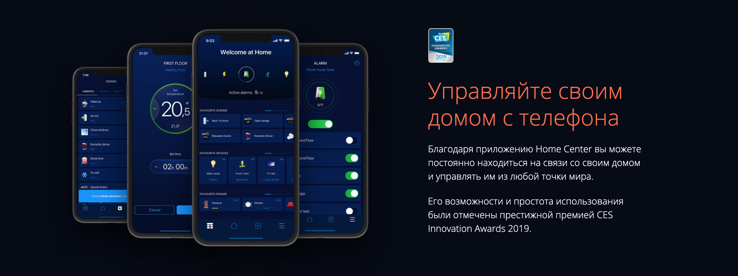
Mobile apps
To control the gateway with a mobile device, install the Home Center app.
You can download the Home Center mobile app here:
- Yubii Home Center for iOS (iPhone)
- Yubii Home Center for Android
You can also scan the codes on your mobile device directly:

Click HERE to keep up to date with the features of the mobile app.
Back To Top
Devices
Zigbee devices
Click HERE to learn more about operating Zigbee devices
Back To Top
Elero devices
The gateway enables control of Elero devices with support for the PLN2 bidirectional communication protocol.
Adding Elero devices
- Open the Configuration interface.
- Go to > Devices .
- Click on

- Select the Elero device.
- To complete the device pairing process, play the device state change at least 3 times using the keyboard buttons
 and
and  or buttons in the interface.
 - Click the Bind button to start.
- Follow the instructions shown on the screen.
- When the pairing process is complete, the devices will be visible in Devices > Elero.
Note: Synchronised pairing is possible. This allows multiple devices to be paired with the controller or remote at the same time. The number of paired devices will be displayed during pairing. Synchronised pairing of Elero devices is available in the Nice/Elero settings.
Back To Top
Z-Wave devices
Adding Z-Wave devices
- Open the Configuration Interface.
- Go to > Devices.
- Click .
- Select Z-Wave Device.
- Set learning mode duration and click Start adding.
- Follow instructions of the device.
There are a few adding options you can choose in the Add Device window:
Options you can choose:
- Device is located far from the gateway (disable it for more security),
- NWI – Network-Wide inclusion (useful for devices that are not near the gateway, but withing networks range),
- Add in security mode if device supports it.
You can also set Learning mode duration – how much time you will have to perform the adding procedure on the device.
Removing Z-Wave devices (If not added)
- Open the Configuration Interface.
- Go to > Devices.
- Click on the Z-Wave tab.
- Click
 .
. - Follow instructions of the device.
Removing Z-Wave devices (If added)
- Open the Configuration Interface.
- Go to > Devices.
- Click next to the device you want to remove from the system.
- Set learning mode duration and click Continue.
- Follow instructions of the device.
Force removing Z-Wave devices
- Open the Configuration Interface.
- Go to > Devices.
- Click next to the device you want to remove from the system.
- Set learning mode duration and click Continue.
- Click which appeared in place of .
- Confirm the action.
- The gateway will try to communicate with the device. If the device responds, the process will by canceled, otherwise it will be removed from the system.
Associations
Associations allow devices to control other devices directly within the Z-Wave network without the participation of the main gateway. Devices such as Dimmer, Switch, Roller Shutter, RGBW Controller can continue to work and operate selected devices even when the main gateway is damaged or turned off (in case of a fire, flood, or system malfunction). You can read more about associations here.
Setting associations
- Open the Configuration Interface.
- Go to > Devices.
- Click the device you want to associate.
- Open Associations tab.
- Select the source EndPoint and Group of the association appropriate for your needs.
- Select the device you want to associate with.
- Click
to set the association. - If the device is battery powered, wake it up manually or wait for next automatic wake up.
Parameters
FIBARO devices allows to customize their operation to user’s needs using configurable parameters. The settings can be adjusted via Z-Wave controller to which the device is added. In the FIBARO interface parameters are presented as simple options in Advanced Settings of the device.
Setting parameters for the device
- Open the Configuration Interface.
- Go to > Devices.
- Click the device you want to change its behavior.
- Open the Parameters tab.
- Find the parameters you’re interested in.
- Adjust the setting.
- Click Save when you finish.
- If the device is battery powered, wake it up manually or wait for next automatic wake up.
If the device changes configuration, you will be asked to refresh the screen.
Copying parameters from other device
Configuration of the device can be copied from another device with the same parameters list.
- Open the Configuration Interface.
- Go to > Devices.
- Click the device you want to copy the parameters to.
- Open the Parameters tab.
- In the Copy configuration from field choose device you want to copy the parameters from.
- Click COPY.
- Save parameters.
- If the device is battery powered, wake it up manually or wait for next automatic wake up.
If the device changes configuration, you will be asked to refresh the screen.
Back To Top
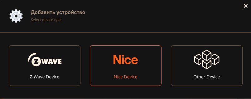
Nice devices
The gateway allows to control Nice doors, gates and screens control units using monodirectional (FLOR and OPERA) and bidirectional (PLN2+) communication protocols. You will find a list of verified devices here.
Adding Nice devices with already programmed transmitter:
If a transmitter is already memorized in the control unit, you can use it to bind the device actions to the gateway.
- Open the Configuration Interface.
- Go to > Devices.
- Click
- Select Nice Device.
- Select Device by using remote.
- Click AUTODETECTION, then on the transmitter press any key twice.
- If the autodetection did not succeed, you can select the protocol manually.
- Select Device type (selecting proper device types is important for correct operation).
- Click Next.
- You will see a list of all actions eligible for your device.
- For gates, doors and barriers: click Bind Mode for an action, then on the transmitter press key responsible for this action twice, repeat for each action.
- For screens: click Bind Mode for any action, then on the transmitter press key responsible for this action twice.
- For each bound action: click Test to check if the action was properly bound and the device responds properly to it.
Adding Nice devices without a programmed transmitter:
If there are no transmitters memorized in the control unit, you must perform action binding directly with the control unit.
- Open the Configuration Interface.
- Go to > Devices.
- Click .
- Select Nice Device.
- Select Device using no remote.
- Select the protocol.
- Select Device type (selecting proper device types is important for correct operation).
- Click Next.
- You will see a list of all actions eligible for your device.
- For gates, doors and barriers: click Bind Mode for an action, then put the Nice device into the transmitter memorization mode according to its manual, then confirm on the Home Center, repeat for each action
(if using Mode II, activate memorization for the specific action). - For screens: click Bind Mode for any action, put the Nice device into the transmitter memorization mode according to its manual, then confirm on the Home Center.
- For gates, doors and barriers: click Bind Mode for an action, then put the Nice device into the transmitter memorization mode according to its manual, then confirm on the Home Center, repeat for each action
- For each bound action: click Test to check if the action was properly bound and the device responds properly to it.
Adding Nice transmitters as scene controllers:
You can add a Nice transmitter to the system and you will be able to start scenes by clicking any remote key.
- Open the Configuration Interface.
- Go to > Devices.
- Click .
- Select Nice Device.
- Select Remote controller only.
- Select the number of keys on the transmitter.
- Click Bind Mode.
- Click any key on the transmitter twice slowly.
- When the status changes to Finished, click Finish.
- After finishing, a new remote will be added to the list of devices. You can use it in scenes as a trigger or create a new scene directly from its Advanced tab.
Back To Top
Linked devices
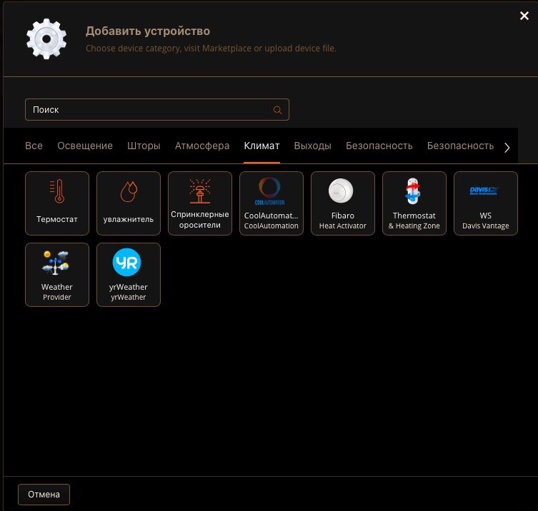
Linked Devices combine several devices into one device. Using this function results in controlling the group of related devices as if they were one single device. The group will be presented in the interfaces as a single device. The gateway offers different Linked Devices types: Thermostats, Humidifiers, Video Gates, Switches, Blinds and Sprinklers.
Thermostats
Heating systems present at our homes are quite complex and they often do not offer any smart home capabilities natively. That’s why you can create a Linked Device, which can act as the given Thermostat.
How does the linked device work?
When you choose the main device for the thermostat it means that the actions of the switches selected in the Linked Device will depend on the readings from the main device.
Depending on the selected devices, different operating modes will be available. If you select a device (Switch/Wall Plug) as a heating device only, the linked device will support modes only for heating. If you select devices for cooling as well, then the Linked Device supports more modes, i.e.: Heat, Cool, Auto, Off.
- Open the Configuration Interface.
- Go to > Devices.
- Click .
- Choose Other Device.
- Click Thermostat.
- Enter the name of the thermostat.
- Choose a Room.
- Choose the main device.
- Select heating and/or cooling devices.
- Save.
How to set schedules for this thermostat?
Heating schedule for this Linked Device is accessible in Climate panel.
You can read more about it in the Climate Schedules section.
Humidifiers/Dehumidifiers
There are many devices on the market which helps in humidifying or dehumidifying. However, these devices may not be smart, nor equipped with Z-Wave radio. Using Linked Devices enables us to create the Humidity Device which can still regulate the humidity at your home.
How does it work?
When you choose the main device for the Humidifier, it means that the actions of the switches selected in this Linked Device will depend on the readings from the main device:
If the humidity (%) drops below your desired humidity range , the devices selected as humidifiers will turn on.
If the humidity (%) rises above your desired humidity range, the devices selected as dehumidifiers will turn on.
If you have set both humidifier and dehumidifier, the Humidity Device will monitor and control the humidity within the given range. If you set only one device, only humidifier or dehumidifier, you won’t be able to set the full range, just the minimum or maximum threshold.
Creating Humidifiers
- Open the Configuration Interface.
- Go to > Devices.
- Click .
- Choose Other Device.
- Click Humidifier.
- Enter the name of the humidifier.
- Choose a Room.
- Choose the Humidity Sensor.
- Set desired humidity range.
- Select humidifiers and dehumidifiers.
- Save.
Video gates
Video gate is a combination of three devices which together can act as a video gate.
We set:
- device which provide us the preview (camera),
- sensor which invokes the bell (input for bell push),
- actor which can activate the door lock or gate (output to open the gate).
Creating Video Gates
- Open the Configuration Interface.
- Go to > Devices.
- Click .
- Choose Other Device.
- Click Video Gate.
- Enter the name of the video gate.
- Choose a Room.
- Choose the Camera.
- Select Input for bell push and Output to open the gate.
- Save.
Switches (a group of switches)
Advanced and complex smart homes often consist of many switches placed within close areas which we want to control at once. Instead of making a scene which will coordinate the operation of all switches, we can group switches into one Linked Device, so all selected device will follow the actions of the “Master Device”.
The Linked Device may act as a device of a few types:
RGBW Controller – linked devices follow parameters such as brightness, color, and power state.
Binary switch – linked devices follow the power state of the master device (appropriate for simple switches, smart plugs).
Color controller – linked devices follow color parameters of the master device.
Multilevel switch – linked devices follow the voltage output of the master device (appropriate for Dimmers).
Creating Switches (grouping)
- Open the Configuration Interface.
- Go to > Devices.
- Click .
- Choose Other Device.
- Choose Switches.
- Enter the name.
- Choose a room.
- Choose Devices, Master Devices and Device Type (RGBW Controller, Binary switch, Color controller, Multilevel switch).
- Save.
Blinds (a group of blinds)
If we have more blinds or awnings in the same area we usually control at once, it is a good idea to grup them in one device. All blinds in that group will follow the master device of our choice.
Usually, devices such as Roller Shutters support few devices of such type, so we need to select appropriate role for the main device:
- blind without positioning,
- blind with positioning,
- venetian blind,
- garage door without positioning,
- garage door with positioning.
Creating Blinds (grouping)
- Open the Configuration Interface.
- Go to > Devices.
- Click .
- Choose Other Device.
- Choose Blinds.
- Enter the name.
- Choose a room.
- Choose Devices (all that you want to group).
- Choose Master Device (the one that other devices will follow).
- Set the Device Role according to your devices:
- Blind without positioning,
- Blind with positioning,
- Venetian blind,
- Garage door without positioning,
- Garage door with positioning.
- Save.
Sprinklers
If you don’t have dedicated watering devices that support Z-Wave or other wireless technology, you can create Sprinklers using Linked Devices.
To create a Sprinkle you need a watering device, for example, a switch connected to a solenoid valve. Optionally, you can add a soil moisture sensor, which will stop watering whenever the set humidity level is reached.
Once you set your Linked Device, you have to configure the watering schedule in the Garden panel. You can read more about it in the Garden Care section.
Creating Sprinklers
- Open the Configuration Interface.
- Go to > Devices.
- Click .
- Choose Other Device.
- Choose Sprinklers.
- Enter the name.
- Choose a room.
- Choose watering devices.
- Select soil moisture sensor (optional).
- Set default watering time.
- Set humidity level to turn off watering.
- Save.
Binary sensors
You can combine multiple binary sensors of the same type to create one main sensor. It will calculate its value from the values of the linked devices using the logical operator you choose.
Available operators:
- AND
- OR
Creating Binary sensors
- Open the Configuration Interface.
- Go to > Devices.
- Click .
- Choose Other Device.
- Choose Binary Sensor.
- Enter the name.
- Choose a room.
- Choose Sensor Type.
- Choose sensors that should be linked.
- Choose which operator should be used to calculate the value.
- Save.
Multilevel sensors
You can combine multiple multilevel sensors of the same type to create one main sensor. It will calculate its value from the values of the linked devices using the mathematical function you choose.
Available functions:
- Average
- Median
- Maximum
- Minimum
Creating Multilevel sensors
- Open the Configuration Interface.
- Go to > Devices.
- Click .
- Choose Other Device.
- Choose Multilevel Sensor.
- Enter the name.
- Choose a room.
- Choose Sensor Type.
- Choose sensors that should be linked.
- Choose which function should be used to calculate the value.
- Save.
Back To Top
Cameras
Adding Cameras
Supported cameras: Your camera must use MJPEG video compression format. H.264, H.265, RTSP, and other streaming formats are not supported in the Configuration Interface.
- Open the Configuration Interface.
- Go to > Devices.
- Click .
- Click IP Camera.
- Choose Manufacturer and Model of your device (select Other if your camera is not on the list).
- Click Next.
- Go to the Advanced tab.
- Enter data for your camera.
- Click Save.
Back To Top
Quick Apps
The concept of Quick Apps is an evolution of plugins and virtual devices found in previous FIBARO gateways.
It is possible to use Quick Apps to prepare integrations with the devices which are not Z-Wave, but offer some API which can be implemented in our Quick App.
Advantages of the new Quick Apps approach:
- easier development,
- simple installation,
- quick configuration,
- usable in scenes.
Creating Quick Apps
- Open the Configuration Interface.
- Go to > Devices.
- Click .
- Choose Other Device.
- Choose Quick App.
- Enter the name of the Quick App.
- Choose a Room.
- Choose the device type .
- Click > next to the created Quick App.
- Go to Edit&Preview tab.
- Click Edit.
- Drag & drop items and enter the Lua code (learn more here).
- Click Save.
Learn more about programming Quick Apps
Downloading file
- Open the Configuration Interface.
- Go to > Devices.
- Click > next to the Quick App.
- Open the Advanced tab.
- Click Download.
Uploading file
- Open the Configuration Interface.
- Go to > Devices.
- Click .
- Choose Other Device.
- Choose Upload File.
- Choose file from your computer.
Types of Quick App devices
- Binary sensor,
- Binary switch,
- Color controller,
- Door lock,
- Door sensor,
- Energy meter,
- Generic device,
- Flood sensor,
- Humidity sensor,
- Multilevel sensor,
- Multilevel switch,
- Player,
- Power sensor,
- Remote controller,
- Roller shutter,
- Smoke detector,
- Temperature sensor,
- Thermostat (auto, cool, heat),
- Weather,
- Wind sensor,
- Window sensor.
Back To Top
Notifications
Setting notifications for the device
- Choose the states of the device you want to be informed about.
Available options depend on the device type. - Choose the interval for the notification:
- Once (will be done once when the event occurs),
- Once per minute (at the full minute),
- Once per hour (at the full hour),
- Once per day (every day at 12.00),
- Once per week (Monday at 12.00).
- Choose the channel of communication:
- E-mail,
- Push.
Back To Top
Settings
Changing Name
- Open the Configuration Interface.
- Go to > Devices.
- Click on the frame next to the device you want to rename.
- Enter new name.
Changing Room
- Open the Configuration Interface.
- Go to > Devices.
- Choose a room from the list.
Categories are used to filter devices in the History window and in the Home Center mobile app.
- Open the Configuration Interface.
- Go to > Devices.
- Click > next to the device.
- Choose one of the categories:
- Lights,
- Blinds,
- Ambience,
- Climate,
- Gates,
- Safety,
- Security,
- Multimedia,
- Remotes,
- Other.
Changing Icon
- Open the Configuration Interface.
- Go to > Devices.
- Click > next to the device.
- Choose one of the default icons or add new one.
Adding an icon
- Open the Configuration Interface.
- Go to > Devices.
- Click > next to the device.
- Click ADD ICON (Size of the icon must be 128px/128px).
Theoretical power consumption
For switches without a built-in power metering feature, you can define the theoretical power consumption.
Whenever the device is turned on, the meter will assume that it consumes power set by the user (in Watts).
- Open the Configuration Interface.
- Go to > Devices.
- Expand the device you want set the theoretical power for.
- Open the Advanced tab.
- Enabled the Theoretical power consumption and set the power.
- Save.
Back To Top
Migrating data
Migrating data from Home Center 2/Lite
If you have Home Center 2 or Home Center Lite you can migrate parts of the configuration to the new gateway.
Prerequisites
- The source and target gateways need to be added to the same FIBARO ID account.
- The source (HC2/HCL) gateway must have version 4.581 or higher.
- The target (HC3) gateway must have version 5.021 or higher.
What will be transferred
- sections, rooms, icons,
- Z-Wave devices assigned to the rooms and their icons,
- parameters of these devices,
- camera devices (but not ones created using plugins),
- associations.
Thermostats will get re-added to the gateway but they will be queued for reconfiguration. They will receive a new ID, default icon, and will be assigned to the default room.
What won’t be transferred
- scenes,
- plugins,
- energy consumption,
- virtual devices,
- camera plugins,
- schedules (watering, climate).
The migration process is irreversible!
Migration from Home Center 2 to Home Center 3
- Visit home.fibaro.com.
- Click Transfer Configuration.
- Choose Source Home Center.
- Choose Target Home Center.
- Click Start Process.
- Source Home Center 2 will reset Z-Wave chip, and all backups will be moved to Home Center 3.
- Log in to Home Center 3 (you can find it via find.fibaro.com).
- Click Finish Migration.
- Home Center 3 will now restore the latest backup.
- Wake up all battery devices.
Configuration on the source gateway (i.e. Home Center Lite or Home Center 2) will be left in read-only state.
You may find it useful for future reconstruction of your scenes and automations.
Migration from Home Center Lite to Home Center 3
- Contact FIBARO Support and ask for setting your Home Center Lite as the artificial donor.
- Visit home.fibaro.com.
- Click Transfer Configuration.
- Choose Source Home Center.
- Choose Target Home Center.
- Click Start Process.
- Home Center Lite will be used to source the data and all backups will be moved to Home Center 3.
- Log in to Home Center 3 (you can find it via find.fibaro.com).
- Click Finish Migration.
- Home Center 3 will now restore the latest backup.
- Wake up all battery devices.
Configuration on the source gateway (i.e. Home Center Lite or Home Center 2) will be left in read-only state.
You may find it useful for future reconstruction of your scenes and automations.
Back To Top
Configuration
Connecting gateways
By connecting gateways, you can greatly increase the range of your Z-Wave network. You can connect multiple Slave gateways to one Master gateways. All of the configuration (like scenes, panels, etc.) is done and stored on the Master gateway.
Requirements
- All of the connected gateways must have the same firmware version.
- Slave gateways must be empty and be restored to factory defaults.
- All of the gateways must be in the same subnetwork.
- You can connect the Home Center 3 gateway with another Home Center 3, Home Center 3 Lite and Yubii Home gateway.
Note: Only the Home Center 3 gateway can be used as a master!
Connecting Slave gateway to Master gateway
- Open the Configuration Interface of the Master gateway.
- Go to > Connect Gateways .
- Under List of gateways in your LAN you will see a list of all gateways detected in your network.
- Click Connect next to the gateway you want to connect it as Slave gateway.
If the gateway has Configure button instead of Connect button, it means it does not meet the requirements (prepare it using the instructions below).
Preparing a gateway for connecting it as a Slave gateway
- Open the Configuration Interface of the gateway you want to connect as a Slave gateway.
- Go to > Connect Gateways .
- Click Prepare Home Center to be Slave.
- Confirm.
- Wait for the gateway to reset to factory defaults.
Back To Top
Rooms and sections
Rooms and sections are used to organize devices to reflect their place in your house.
Sections
Sections represent areas in your house (e.g. floors) and rooms can be assigned to them.
Adding sections
- Open the Configuration Interface.
- Go to > Rooms.
- Click Manage sections.
- Type in a new name and click plus icon.
Deleting sections
- Open the Configuration Interface.
- Go to > Rooms.
- Click Manage sections.
- Click next to the section you want to delete.
Rooms
Rooms represent rooms and other places in your house (e.g. living room, corridor) and devices can be assigned to them.
Adding rooms
- Open the Configuration Interface.
- Go to > Rooms.
- Click Add room.
- Set room information:
- Category – categories are used for filtering rooms by type,
- Name – name of the room,
- Section – section of the house the new room will be assigned to,
- Icon – icon that will represent the room.
- Save.
Editing rooms
- Open the Configuration Interface.
- Go to > Rooms.
- Click
 in the top right corner of the room icon.
 - Click Edit.
- Edit room information:
- Category – categories are used for filtering rooms by type,
- Name – name of the room,
- Section – section of the house the new room will be assigned to,
- Icon – icon that will represent the room.
- Save.
Deleting rooms
- Open the Configuration Interface.
- Go to > Rooms.
- Click in the top right corner of the room icon.
- Click Delete.
- Confirm.
Default room
New devices will be automatically assigned to the default room.
To choose the default room:
- Open the Configuration Interface.
- Go to > General.
- Set Default room (under the section: Main Sensors).
Back To Top
Network settings
Checking network status
There are two ways to check network status of the gateway:
1) By checking the diodes on the Home Center housing:
Kompozycja 7 Internet diode
Copper – connected to Internet
Red – disconnected from Internet
Kompozycja 6 LAN diode
Copper – connected to LAN
Fast pulsing copper – connecting to LAN
Kompozycja 5 Wi-Fi diode
Copper – connected to Wi-Fi
Fast pulsing copper – connecting to Wi-Fi
Red – incorrect Wi-Fi password / other error
Green – Wi-Fi in Access Point mode
2) By checking the network status in the Configuration Interface:
> Network > Internet Status
LAN connection
Connecting to LAN network:
- Connect the gateway to your home’s Internet router using the provided Ethernet cable.
- Open the Configuration Interface.
- Go to > Network > LAN connection.
- Set connection type :
- DHCP – IP will be assigned dynamically by the router,
- Static – you must enter all settings manually, remember to reserve the IP address for the gateway in the router’s settings.
- Set remaining options.
How to set static IP Address:
Setting static IP address on a gateway consists of at least three steps:
1. Determine the IP of the gateway and decide whether is it the IP you want to leave permanently.
2. Configure the home router so that it also keeps the IP for this device.
3. Set the selected IP in the Configuration Interface:
- Open the Configuration Interface.
- Go to > Network > LAN connection.
- Set Network connection type to Static/Manual.
- Input the IP address you want to set for the gateway.
How to set dynamic IP Address:
- Open the Configuration Interface.
- Go to > Network > LAN connection.
- Set Network connection type to DHCP.
Wi-Fi connection
Connecting to a Wi-Fi network:
- Open the Configuration Interface.
- Go to > Network > Wi-Fi connection.
- Enable Wi-Fi.
- Click Search & Connect to Network
- If your network is on the list:
- Select the network from the list and click Next,
- Enter password if needed.
- If your network is not on the list:
- Select Different/Hidden and click Next,
- Enter the network name (SSID) and security details.
- If your network is on the list:
- Click Connect.
How to set static IP Address:
Setting static IP address on a gateway consists of at least three steps:
1. Determine the IP of the gateway and decide whether is it the IP you want to leave permanently.
2. Configure the home router so that it also keeps the IP for this device.
3. Set the selected IP in the Configuration Interface:
- Open the Configuration Interface.
- Go to > Network > Wi-Fi connection.
- Set Network connection type to Static/Manual.
- Input the IP address you want to set for the gateway.
How to set dynamic IP Address:
- Open the Configuration Interface.
- Go to > Network > Wi-Fi connection.
- Set Network connection type to DHCP.
Resetting network settings
Resetting network settings will restore Wi-Fi and LAN factory settings.
Using buttons on the cover:
- Hold the Kompozycja 3 button for 20 seconds.
- LAN and Wi-Fi indicators will blink red.
Using Recovery Interface:
- Open the Recovery Interface.
- In Network Settings section click Reset.
Secure connection
The gateway can use HTTP and HTTPS protocols for communication. Use HTTPS to ensure security by encrypting communication.
To set connection type:
- Open the Configuration Interface.
- Go to > Network > Secure Connection.
- Select connection type:
- HTTP – standard connection without additional encryption,
- HTTPS – secure encrypted connection,
- HTTP/HTTPS – the gateway will accept both types of connection.
- Save.
, in this case, do the following:
1) Download certificate from the Secure Connection section in Network settings and install it on your system (and browser),
2) Use the gateway’s serial number to connect locally, i.e. use serial_number.local, e.g. https://hc3-00000001.local
- Download the certificate.
- In the Windows Start menu search for mmc app and open it.
- In the MMC (Microsoft Management Console) app go to File > Add/Remove Snap-In.
- Add Certificate Snap-in:
- Certificates > Select “Computer account” > Next > Next > OK.
- Now go to Certificates > Trusted Root Certification Authorities and right-click on “Certificates”
- Import the certificate.
- Find the certificate downloaded from the FIBARO Home Center 3.
- Import it.
- Done.
- Your connection with the gateway is now secure.
Back To Top
Users and access
Users
User roles
- can switch devices on/off, see the state and history data of devices.
Adding users
- Open the Configuration Interface.
- Go to > Access > Users.
- Click Add user.
- Message with local password for the new account will be sent to entered e-mail address.
Sharing remote access via FIBARO ID
Only owner can share access to the gateway via FIBARO ID.
- Log into Remote Access with your FIBARO ID.
- Chose the gateway which you want to add the user to.
- Click > next to the Open button.
- Click Add user button.
- Enter FIBARO ID e-mail address of the user you want to give access to your gateway.
- Click Add.
- Open the Configuration Interface.
- Go to > Access > Users.
- Click Synchronize.
- User with access via FIBARO ID will have icon on the list.
- If the user didn’t already have an account, message with local password for the new account will be sent to entered e-mail address.
Giving permissions to user
For a new user to be able to use the gateway, admin must give it appropriate privileges.
- Open the Configuration Interface.
- Go to > Access > Users.
- Click Manage Access on the user list.
- Select sections and/or devices to give the user access to them.
- Click Save.
Managing user’s mobile devices
- Open the Configuration Interface.
- Go to > Access > Users.
- Click > next to the user.
- To add a mobile device to the gateway, log in to the mobile application on the given device.
- To remove a mobile device from the gateway, click the next to it and then confirm action by clicking DELETE.
- Select “Send notifications” checkbox if you want to receive notifications on mobile devices.
Setting PIN for the user
- Open the Configuration Interface.
- Go to > Access > Users.
- Click > next to the user
- Enter the PIN code. Remember it, you will need this to change it and to disarm the alarm.
- Select “Ask for PIN when arming” checkbox to increase safety and prevent unintentional arming.
Setting local password for the user
- Open the Configuration Interface.
- Go to > Access > Users.
- Click the > next to the user.
- Enter new local password.
- Click Save.
Transferring admin privileges
- Open the Configuration Interface.
- Go to > Access > Users.
- Choose the non-admin user to transfer the rights.
- Click > next to this user.
- Click TRANSFER ADMIN ROLE.
- Click Transfer to confirm.
- Message about transferring the admin role will be sent to the chosen user’s e-mail address.
- User has to log into the gateway. In the top right corner click its e-mail address and choose Account Settings.
- Click ACCEPT to accept the transfer.
Remote access
Remote Access allows you to connect and manage your control panel and devices from a remote area outside your home. The gateway must be connected to the Internet and powered on.
Enabling remote access
Remote access is enabled by default.
To enable/disable remote access:
- Open the Configuration Interface
- Go to > Access > Remote Access.
- Enable/disable Remote Access toggle.
Support Access
You should enable Support Access when you have an issue that you cannot resolve on your own. By granting access to your gateway, the support team may be able to find problems faster.
Enabling Support Access
To enable support access:
- Open the Configuration Interface.
- Go to > Access > Remote Access.
- Enable Support Access toggle.
The FIBARO System can be configured on your own or by a certified FIBARO Installer. In case your system has been configured by the FIBARO Installer, the Installer Access may facilitate his later work by allowing him to monitor and access to selected information of your system.
Enabling Installer Access
Enabling Installer Access enables FIBARO Installer to check up on your system and fix smaller issues remotely.
Setting Installer permissions
You can allow installer to:
- monitor your gateway (current status, active LEDs, status of services, backups etc.),
- give access for 24h to perform remote actions on your gateway.
Enter Installers FIBARO ID and click Add Installer to give him access to your gateway. Choose mobile devices that can receive push notifications from the installer.
Back To Top
Time and units
The gateway gives you possibility to set the time, time zone, units and even separators!
To adjust the settings:
- Open the Configuration Interface.
- Go to > General.
- Open the Time & Units tab.
Now you can change settings, such as:
Date and time:
- Time zone,
- Date and time (you can get it from the NTP server or set manually),
- NTP server,
- Date format,
- Hour format (12-hour, 24-hour),
- Date,
- Time.
Units and separators:
- Temperature unit (Celsius, Fahrenheit),
- Wind speed unit (km/h, mph),
- Decimal mark (comma, dot).
Back To Top
Location
Setting location in the gateway allows you to personalize your smart home experience.
Location is used for weather retrieving and can also be useful for automation purposes.
Once you set your home and/or work location, you can trigger certain scenes via entering or leaving the zone.
To set your home location:
- Go to > General > Location (tab).
- Drag the map so that you see your home address.
- Click the location of your home to update the pin.
- Set the radius accordingly to your house and property size, e.g. 100m.
- Save.
To add another location:
- Go to > General > Location (tab).
- Click Add Location.
- Enter the name of your new location, e.g. Work.
- Drag the map and click the place of your work.
- Set the radius of your work, e.g. 300 m.
- Save.
Back To Top
VoIP
Home Center VoIP server
Home Center can act as a VoIP server. Once configured, it can manage the VoIP connections between the clients. To use VoIP on end devices, you must use a compatible VoIP app on your mobile device. The Home Center gateway must be reachable via the given medium of transmission and configured first.
Adding clients
- Open the Configuration Interface.
- Go to > VoIP.
- Click Add VoIP client.
- Enter Display name, VoIP username, and VoIP password.
- Click Add to Save.
- The new VoIP user has been created and it is at the end of the list.
You can always temporary disable the user without removing him by changing his Active state.
VoIP in mobile apps
Each VoIP app may differ in configuration, but the most important is the IP of the Home Center gateway and user credentials.
When you configure VoIP on Home Center, you set up users and their passwords/pins.
During configuration on your mobile device you need to enter those things:
- The IP address of the gateway.
- User credentials for a specified earlier VoIP user.
Back To Top
Z-Wave
This screen is dedicated to Z-Wave configuration.
Z-Wave Settings allows to:
- Reconfigure all devices,
- Reconfigure mesh network (You can choose if you want to configure entire Z-Wave network or single devices),
- Broadcast “Node Information” frame,
- Add secondary controller,
- Transfer controller,
- Reset energy metering,
- Reset Z-Wave,
- Enable devices polling,
- Poll unavailable devices,
- Mark nodes as unavailable,
- Set devices polling time interval,
- See number of devices added to your gateway.
Back To Top
Automation
Scenarios
Click HERE to find out more about the Scenarios.
Back To Top
Scenes
They can integrate multiple devices included in your system and may be activated by weather conditions, a series of intuitive timers or various sensor/module states.
There are two types of scenes to create in the interface:
- Block Scenes are easy to build. Using number of available customizable blocks complex scenes can be visually created. It is not possible to implement all functionalities of the FIBARO System with Block Scenes, but are the best way for a basic user to enhance home automation.
- Lua Scenes are most advanced, but allow user to fully utilize all FIBARO System capabilities. Such scenes are based on the Lua programming language and require basic programming skills.
Creating scenes
- Open the Configuration Interface.
- Go to > Scenes.
- Click Add scene.
- Choose scene type.
- Set basic settings:
- Name – name of the scene.
- Run scene – choose if the scene will be run automatically (when conditions are met) or manually (ignore conditions).
- Allow to restart a running scene – if set toYes, every new activation of the scene restarts it, if set to No, scene can’t be activated again if it is already running.
- Category – categories are used for filtering scenes by type.
- Icon – icon that will represent the scene.
- Save.
Read further on creating scene using blocks here.
Editing scenes
- Open the Configuration Interface.
- Go to > Scenes.
- Click the to edit the scene.
- Edit scene.
- Save.
Deleting scenes
- Open the Configuration Interface.
- Go to > Scenes.
- Click the to delete the scene.
- Click Delete.
Duplicating scene
- Open the Configuration Interface.
- Go to > Scenes.
- Click next to the scene you want to duplicate.
- Click Copy to confirm.
Converting Block Scene to Lua Scene
- Open the Configuration Interface.
- Go to > Scenes.
- Click next to the scene you want to duplicate.
- Click Copy & Convert to confirm.
Managing scene settings
Changing name
- Open the Configuration Interface.
- Go to > Scenes.
- Click on the frame next to the scene you want to rename.
- Enter new name.
Disabling/enabling
- Open the Configuration Interface.
- Go to > Scenes.
- Click Disable/Enable button next to the scene you want to disable/enable.
Changing triggering mode (manual/auto)
In auto mode, the scenes runs automatically, when triggers and conditions are met, in manual mode the scene can be triggered only manually by the user.
- Open the Configuration Interface.
- Go to > Scenes
- Click toggle to change triggering mode.
Changing other settings
- Open the Configuration Interface.
- Go to > Scenes.
- Click > to expand the scene.
- Edit scene settings:
- Allow to restart a running scene – if set toYes, every new activation of the scene restarts it, if set to No, scene can’t be activated again if it is already running.
- Category – categories are used for filtering scenes by type.
- Scene hidden – check to hide scene from interfaces.
- Require PIN to run – check if you want to protect the scene by requiring PIN to run it.
- Icon – icon that will represent the scene.
- Save.
Running scenes
- Open the Configuration Interface.
- Go to > Scenes.
- Click Play button next to the scene which you want to run.
- Open the Configuration Interface
- Go to > General > Variables.
- Click Add Variable.
- Choose Standard or Enumerated variable.
- Enter the Name and Value/Values.
- Click Add.
Custom events may be used to expand the functionality of scenes. Similar to variables, they can be used to connect different scenes, but they do not store any additional information, only that something happened (specified by you). You can emit your custom event in scenes and QuickApps, then use it to trigger other scenes.
Creating an event
- Open the Configuration Interface
- Go to > General > Events.
- Click Add Event.
- Choose the name for the event.
The name cannot contain:- digits at the beginning of the name,
- special characters (only letters from English alphabet),
- spaces.
- Fill in the description.
- Click Add.
Back To Top
Block Scenes
Back To Top
Lua Scenes
Back To Top
Climate schedules
Temperature schedules allow for automatic control of heating and cooling for each area (zone) of the house.
Devices controlling temperature (e.g. thermostats) are required to a create the temperature zone. You can create your own thermostats by connecting a temperature sensor and actor that turns heating/cooling on/off.
Creating Thermostats
- Open the Configuration Interface.
- Go to > Devices.
- Click .
- Choose Other Device.
- Click Thermostat.
- Enter the name of the thermostat.
- Choose a Room.
- Choose the main device.
- Select heating and/or cooling devices.
- Save.
Adding zones
- Open the Configuration Interface.
- Go to > Climate.
- Click Add Zone.
- Select how zones should be created:
- Automatically – zones will be created automatically for all rooms with temperature devices.
- Manually – manually select devices to be included in the new zone.
Zone modes
- Schedule – zone works according to the set schedule.
- Manual – constant temperature is set for a specified time duration.
- Vacation – constant temperature is set until disabled.
Configuring zone schedule
- Open the Configuration Interface.
- Go to > Climate.
- Click > to expand the zone.
- Select operating mode:
- Heating: devices increase the temperature to reach the temperature setpoint,
- Coolin: devices decrease the temperature to reach the temperature setpoint,
- Auto: devices determine if they should cool or heat to reach the temperature setpoint,
- Off: devices are always off.
- Set start times for periods by moving the sliders or entering them below.
- Enter temperatures to be set on each period.
- Save.
If you want to use the same schedule on multiple days, you can set it once, then copy it to the remaining days.
Editing zone name and devices
- Open the Configuration Interface.
- Go to > Climate.
- Click the to edit the zone.
- Change name or devices in the zone.
- Save.
Back To Top
Garden care
Watering schedules allow for automatic control of your sprinklers.
You need to create sprinklers first in order to configure watering schedules.
Creating sprinklers
- Open the Configuration Interface.
- Go to > Devices.
- Click .
- Choose Other Device.
- Choose Sprinklers.
- Fill in new sprinkler settings:
- Enter the name.
- Choose a room.
- Choose watering devices.
- Choose watering default time.
- Select soil moisture sensor (optional).
- Set humidity level to turn off watering.
- Save.
Editing sprinklers
- Open the Configuration Interface.
- Go to > Devices.
- Find your sprinkler on the list.
- Click > next to the sprinkler you want to edit.
- Click EDIT DEVICE.
- Edit settings and Save.
Adding and configuring watering schedules
Adding watering schedule
- Open the Configuration Interface.
- Go to > Garden.
- Click Add Schedule.
- Insert name for watering schedule.
- Click > to expand the schedule.
- Choose days to apply the schedule for.
- Click Save.
Adding watering sequences to a schedule
- Click > to expand the schedule.
- Click ADD SEQUENCE to add new sequence to the schedule.
- Choose devices to use in this sequence.
- Click > next to the sequence to configure it.
- Set order of the sprinklers and modify duration if needed.
- Repeat steps 2-5 to add and configure more sequences.
- Click Save.
Back To Top
Profiles
At least one profile is required. There are four default profiles, but you can add more if you want to.
Creating profiles
- Open the Configuration Interface.
- Go to > Profiles.
- Click Add Profile.
- Name the new profile.
- If you want to copy settings from another profile, select it in Based on field.
- Select icon for the new profile.
- Click Add.
Configuring profiles
- Open the Configuration Interface.
- Go to > Profiles.
- Set how your scene, devices and zones should work in each profile.
Editing profile name and icon
- Open the Configuration Interface.
- Go to > Profiles.
- Next to profile name click .
- Click Edit.
- Change name or click new icon.
- Save.
Deleting profiles
- Open the Configuration Interface.
- Go to > Profiles.
- Next to profile name click .
- Click Delete.
- Confirm.
Activating profiles manually
- Open the Configuration Interface.
- On the top bar click the name of current profile.
- Click on the name of the profile you want to activate.
Back To Top
Alarms
Alarm feature allows to create alarm zones using sensors in your system. Breaching any sensor in an armed zone will trigger an alarm. The system will inform you about an alarm, you can also activates scenes when alarm triggers.
icon indicates the occurrence of an alarm. When alarm occurs, icon becomes red and clickable. Clicking
icon will direct you to Settings > Alarm so that you can see in which zone the alarm occurred.
Adding zones
- Open the Configuration Interface.
- Go to > Alarm.
- Click Add Zone.
- Name the new zone.
- Select rooms or devices to be included in the new zone.
Arming/disarming zones
Arming zone will arm all devices in this zone, and disarming the zone will disarm all devices in this zone.
- Open the Configuration Interface.
- Go to > Alarm.
- Under Arming column click the toggle to arm/disarm the zone.
- Enter PIN if required (default PIN is 1111).
Setting PIN
The default PIN is 1111, we strongly recommed changing it.
- Open the Configuration Interface.
- In top right corner click your user name.
- Choose Account Settings from the menu.
- In Alarm Settings section:
- Set 4-digit PIN.
- Choose if you want the gateway to ask for PIN also while arming (not only disarming).
- Save.
Setting delay for arming/disarming
- Open the Configuration Interface.
- Go to > Alarm.
- Enter delay time (in seconds) for the zone:
- Entry delay – the alarm will delay triggering to allow you to disarm the zone when you enter it.
- Exit delay – the alarm will delay arming to allow you to leave the zone without triggering it.
Editing zone name and devices
- Open the Configuration Interface.
- Go to > Alarm.
- Click the to edit the zone.
- Change name or devices in the zone.
- Save.
Back To Top
Maintenance
System report
The system allows to print a full report of the configuration for easier management and diagnostics.
The report gives you all the necessary information about the system at first glance. This can be useful for example for finding devices needing battery replacement or creating scenes.
The report includes information about:
- network configuration,
- rooms,
- devices,
- scenes,
- users,
- alarm zones,
- climate zones,
- garden schedules,
- profiles,
- general settings,
- variables and events,
- backups.
To generate system report:
- Open the Configuration Interface.
- Go to > General.
- Click Generate next to Generate system report
- A new window with the report will open ready to print.
Back To Top
Recovery Mode
Recovery Mode allows retrieving the gateway operating system in case of technical problems, e.g. when the Configuration Interface is not reachable after update.
Using Recovery Mode you can repair the system or restore the default configuration (to its initial state).
The gateway maintains two copies of the system (System A and B) to ensure safety of your data during the firmware update. Updating system is always performed on the inactive system, then the gateway switches to it, thus maintaining copy of your data from before the update. In case of any problems, you can switch back to it.
Entering Recovery Mode
Using buttons on the cover:
- Press and hold the Kompozycja 8 button for 15s, release when all indicators blink red at once.
- Press and hold the Kompozycja 3 button, release when indicators start to blink a sequence from left to right.
- When Kompozycja 3 indicator turns red, open the Recovery Interface in your Internet browser, as you would normally open the Configuration Interface.
Using Configuration Interface:
- Open the Configuration Interface.
- In top right corner click .
- Choose Recovery Mode from the menu.
- Confirm.
- Wait for the system to reboot, Kompozycja 3 indicator will turn red.
- Refresh the browser tab.
In case of problems after updating your system, you can quickly repair it by using auto-repair. It will switch to copy of your system from before the last system update.
- Enter the Recovery Mode.
- Click Auto-repair.
- Confirm.
You can switch between system A and B at any moment using the Recovery Mode, e.g. when current system encounters a problem.
- Enter the Recovery Mode.
- Click Switch to System A/B.
- Choose if you want to restore Latest version or use Local file.
- Confirm.
This feature allows you to restore the operating system to the latest version or version from a file without deleting any user data. Only the system will be refreshed.
Depending on how you have entered the Recovery Mode, different system will be available for repairing: inactive when entered via configuration interface or active when entered using Kompozycja 3 button. Switch system to repair the other one.
- Enter the Recovery Mode.
- Click Repair System A/B.
- Choose if you want to restore Latest version or use Local file.
- Confirm.
Resetting network settings
In some cases, problems with the gateway may be caused by changes in the network configuration of the environment in which the gateway is located. If you do not want to restore the entire system to factory settings, try resetting the network settings first, as this may solve your problems with the gateway.
- Enter the Recovery Mode.
- Click Reset in the Reset Network Settings section.
- Confirm.
CAUTION: The configuration will be removed and lost if not backed up.
This feature allows you to restore the operating system to the latest version or version from a file and delete all data from this system (users, devices, scenes etc.).
Depending on how you have entered the Recovery Mode, different system will be available for recovering: inactive when entered via configuration interface or active when entered using Kompozycja 3 button. Switch system to recover the other one.
- Enter the Recovery Mode.
- Click Recover System A/B.
- Choose if you want to restore Latest version or use Local file.
- Confirm.
CAUTION: The whole configuration will be removed and lost if not backed up.
This feature allows you to restore the gateway to factory settings. It means factory software version will be restored and all data from system A and B will be deleted (users, devices, scenes etc.).
- Enter the Recovery Mode.
- Click Factory Reset button under Network Status section.
- Check “Yes, I’m sure and I know what I’m doing” checkbox.
- Confirm action.
Back To Top
Updates
Updating the gateway
The gateway will inform you if there is a new update to be installed with Kompozycja 3 . Updates may include new features, improvements, and bug fixes.
We recommend installing those updates as soon as they are available to ensure best operation and security.
Updating the gateway in not possible via the Remote Access.
To update the gateway:
- Go to > Update > Home Center.
- Click Download Update for the respective update.
- Wait for the update to be downloaded.
- Determine whether you want to do the cloud backup, local backup or no backups before the update.
- Accept Terms & Privacy Policy.
- Click Install Update.
- Click Update to confirm the update.
Updating connected devices
Updating the devices is not possible via the Remote Access.
To update devices:
- Go to > Update > Devices (tab).
- Click Update next to available update or select multiple and click Install Updates.
- Read the changelog and check the tickbox that you want to continue.
- Click Update.
Back To Top
Backups
Backups of your entire system are the best way to prevent losing configuration data in case of any issues or unintentional changes. We recommend creating backups regularly.
There is limited storage for backups! You can store up to 2 local and up to 10 MB of backups in our cloud service. If you need more you can download and save them on your computer.
Creating backups
Creating cloud backups
Cloud backups require configured and enabled Remote Access (see link enable remote access).
- Open the Configuration Interface.
- Go to > Backup > Cloud Backup.
- Click Create backup.
- Enter a description for the new backup.
- Confirm.
- Wait for the process to end (interface will be unavailable while creating the backup).
- The backup will be added to your cloud backups.
Creating local backups
- Open the Configuration Interface.
- Go to > Backup > Local Backup.
- Click Create backup.
- Enter a description for the new backup.
- Confirm.
- Wait for the process to end (interface will be unavailable while creating backup).
- The backup will be added to your local backups.
Downloading local backup file
- Open the Configuration Interface.
- Go to > Backup.
- Click Download next to the local backup you want to download.
- File with last local backup will be downloaded on your computer.
Restoring backups
Cloud backups require configured and enabled Remote Access (see link enable remote access).
Restoring backup from the list
- Open the Configuration Interface.
- Go to > Backup.
- Next to backup you want to restore click Restore.
- If provided with options:
- Click Restore & Convert – backup created on earlier software version will be restored on the current version.
- Click Restore with version – backup created on earlier software version will be restored with that version.
- Confirm.
- Wait for the process to end (interface will be unavailable while restoring backup).
Restoring local backup from file
- Open the Configuration Interface.
- Go to > Backup > Local Backup.
- Click Upload backup.
- Select backup file on your computer.
- Backup will be added to your list.
- If you want to restore the backup, click Restore next to it.
Back To Top
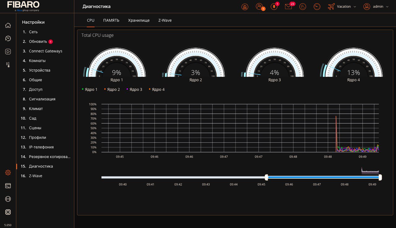
Diagnostics
Diagnostics screen presents technical data about actual use of particular components, i.e. CPU, RAM, Storage, Z-Wave. This can help in troubleshooting or understanding how certain actions influence our system.
There are 4 tabs:
- CPU – shows the actual use of each core,
- RAM – shows the actual use of RAM memory and indicated how much percent is used for what purpose,
- Storage – shows the status of internal memory,
- Z-Wave – lists all Z-Wave devices that are not configured or without templates.
Back To Top
Integrations
Assistants
Are you tired of constantly searching for functions on your smartphone? Do you want your smart home to work on demand? This is possible thanks to the assistants. Check out the assistants that work with FIBARO!
Assistants that works with FIBARO:
- Google Assistant,
- Amazon Alexa,
- FIBARO Smart Home Bot.
Read articles about assistants:
- Google Assistant – FIBARO integration
- Amazon Alexa – FIBARO integration
- Amazon Alexa – Frequently Asked Questions
- List of FIBARO Smart Home Bot commands
- Connecting FIBARO Smart Home Bot
- FIBARO Smart Home Bot – Frequently Asked Questions
Back To Top
Security
Reporting a security issue
There are two ways to report a security issue:
- Report directly on FIBARO Security (preferred)
- Click on the “Report a security vulnerability” link. This file will expand the list of items to be filled.
- Please provide all required elements and confirm.
- Complete the form, which will be immediately incorporated into the Security Team workflow.
- Send an e-mail
- Send an e-mail to [email protected]
IMPORTANT! Do not post any information about the vulnerability to the public issue trackers or discuss it in public. FIBARO security team will investigate your report and then work with you and the project maintainer to create a fix. Once the fix is ready and released, FIBARO will announce the information to a wider audience.
Security report is acknowledged by e-mail within 3 working days by Fibaro security team. You will be updated using e-mail communication on the status of the issue once the team has started working on the issue and additionally every 2 weeks after that.
Back To Top
- Manuals
- Brands
- FIBARO Manuals
- Gateway
- Home Center 3
- Installation manual
-
Contents
-
Table of Contents
-
Bookmarks
Quick Links
Related Manuals for FIBARO Home Center 3

Summary of Contents for FIBARO Home Center 3
-
Page 1
Installation manual… -
Page 2
This manual describes the first installation of the Home Center 3 smart home gateway. To see a full description of all features and how to configure them visit our website: manuals.fibaro.com/home-center-3… -
Page 3: Table Of Contents
Table of contents Important safety information……Installation………… First configuration……… Remote access……….Mobile apps……….Status indicators……….. Buttons…………Specifications……….Warranty terms and conditions….. Regulatory information……..
-
Page 4: Important Safety Information
Caution! Do not attempt to disassemble, repair or modify this product yourself. • Any repair should be performed only by an authorized FIBARO service. This product is designed for indoor use only. Do not use outside! • Do not expose this product to moisture, water, or other liquids.
-
Page 5
Note Do not place the product in metal boxes or on metal surfaces • for best radio performance. Create system backups regularly to prevent losing your system • configuration. Connect (LAN) interface to your local network only. Make sure your •… -
Page 6: Installation
Installation Using Ethernet cable (recommended) 1. Connect the gateway to your home’s Internet router using the provided Ethernet cable. 2. Plug the provided power adapter into an outlet and connect it to the gateway. 3. The gateway will turn on and indicator will turn copper.
-
Page 7
Using Wi-Fi only 1. Plug the provided power adapter into an outlet and connect it to the gateway. 2. The gateway will turn on and indicator will turn copper. 3. Connect your computer to Wi-Fi network created by the gateway. You will find Wi-Fi SSID (name) and password on the bottom of the device. -
Page 8: First Configuration
First configuration 1. Go to find.fibaro.com. 2. List of all gateways in your home network will be displayed. (If you are connected to the Wi-Fi network created by the gateway, skip to step 4.) 3. Click Open next to gateway you want to configure.
-
Page 9: Remote Access
Remote access To control the gateway outside your house: 1. In your Internet browser go to id.cloud.fibaro.com. 2. Create an account. 3. Go to Remote Access and add your gateway. Mobile apps To control the gateway with a mobile device, install the Home Center app.
-
Page 10: Status Indicators
Status indicators Power Installer Copper – powered Copper – installer assigned Green – remote support enabled Red – installer not assigned Internet Copper – connected to Internet Recovery Red – disconnected from Internet Red – in Recovery Mode Fast pulsing green – creating backup Slow pulsing copper – update available Copper – connected to LAN Fast pulsing copper – connecting to LAN Smart Home Slow pulsing copper – adding mode Wi-Fi…
-
Page 11: Buttons
Buttons Power Click Wake up Hold for 5s Sleep mode Hold for 15s Restart Recovery Hold during startup Put in Recovery mode Hold for 10s Switch between Dynamic and Static IP: blink yellow: IP set to Dynamic • blink green: IP set to Static •…
-
Page 12: Specifications
Specifications General information Model FGHC3-001 Quad-core Arm Cortex A53 (1.2GHz) RAM 2GB LPDDR3 Flash memory 8GB eMMC Power supply 12V DC (adapter included) Operating temperature 0-40°C Operating humidity max. 75% relative humidity (non-condensing) Network interface 10/100 (Base-T) Ethernet via RJ45 connector 1 (2.0) Power connector barrel connector 5.5mm x 2.5mm (female)
-
Page 13
Radio Communication Max. transmitting Protocol Radio frequency band power 868.0-868.6 MHz +14dBm 869.7-870.0MHz AU, NZ 915.0-928.0MHz +5dBm Z-Wave (500 series) 902.0-928.0MHz +5dBm 915.0-928.0MHz -2dBm 920.9-923.1MHz +7dBm 2.4GHz 2400.0-2483.5MHz +20dBm Wi-Fi (802.11 b/g/n/a/ac) 5GHz 5150.0-5250.0MHz +14dBm EU, THA 433.05-434.04Mhz +10dBm 433Mhz AU, NZ, CL, BR 433.05-434.04Mhz +14dBm… -
Page 14: Warranty Terms And Conditions
PLN 1,182,100 paid in full, other contact Customer should contact information is available at: www.fibaro.com Manufacturer via the email address given at (hereinafter “the Manufacturer”) guarantees that fibaro.com/en/support/. the device sold (hereinafter referred to as: “the 8. After the complaint has been properly submitted, Device”) is free from material and manufacturing…
-
Page 15
Z-Wave product and should work with devices Manufacturer. from other producers. Each certified, Z-Wave • damages caused by operating or storing the compatible device, may be added to FIBARO device in extremely adverse conditions, i.e. System. high humidity, dust, too low (freezing) or too high ambient temperature. -
Page 16: Regulatory Information
Directives 2014/53/EU, 2011/65/EU and 2015/863. The full text of the EU declaration of conformity is available at the following internet address: manuals.fibaro.com The device is restricted to indoor use only when operating in the 5150 MHz to 5250 MHz frequency range.
-
Page 17
Notebook… -
Page 18
Notebook… -
Page 19
Notebook… -
Page 20
105466410101…
перейти к содержанию
FIBARO FIB-HOMEC3 Home Center 3 Интеллектуальный дом

Важная информация по безопасности
Внимательно прочтите это руководство перед установкой и использованием продукта.
Внимание!
- Производитель не несет ответственности за любые убытки или ущерб, возникшие в результате несоблюдения инструкций. Сохраните это руководство в надежном месте для использования в будущем.
- Этот продукт не игрушка. Беречь от детей и животных.
- При настенном монтаже не размещайте изделие выше 2 метров от пола.
Внимание!
- Не пытайтесь самостоятельно разбирать, ремонтировать или модифицировать этот продукт. Любой ремонт должен выполняться только авторизованным сервисом FIBARO.
- Этот продукт предназначен только для использования внутри помещений. Не используйте его снаружи!
- Не подвергайте изделие воздействию влаги, воды или других жидкостей. Никогда не ставьте сосуды с водой рядом с изделием.
- Не используйте продукт вне рекомендуемых диапазонов температуры и влажности.
- Держите изделие вдали от источников тепла и не подвергайте его воздействию прямых солнечных лучей.
- Не накрывайте изделие во время работы.
- Не кладите ничего на изделие.
- Не подключайте к интерфейсам кабели длиннее 3 метров.
Внимание
- Не помещайте продукт в металлические коробки или на металлические поверхности для обеспечения наилучших характеристик радиосвязи.
- Регулярно создавайте резервные копии системы, чтобы предотвратить потерю конфигурации системы.
- Подключайте (LAN) интерфейс только к вашей локальной сети. Убедитесь, что ваша локальная сеть защищена и доступна только для доверенных устройств.
Установка
Использование кабеля Ethernet (рекомендуется)
- Подключите шлюз к домашнему интернет-маршрутизатору с помощью прилагаемого кабеля Ethernet.

- Вставьте прилагаемый адаптер питания в розетку и подключите его к шлюзу.

- Шлюз включится, и индикатор станет медным.


Использование только Wi-Fi
- Вставьте прилагаемый адаптер питания в розетку и подключите его к шлюзу.

- Шлюз включится, и индикатор станет медным.
- Подключите свой компьютер к сети Wi-Fi, созданной шлюзом. Вы найдете Wi-Fi SSID (имя) и пароль на нижней части устройства.

Первая конфигурация
- Отсканируйте QR-код и загрузите приложение Yubii Home Center.
- Запустите приложение и следуйте отображаемым инструкциям.
Альтернативная конфигурация
- Перейдите на find.fibaro.com (используйте 10.42.0.1, если вы подключаетесь к сети Wi-Fi, созданной шлюзом, и переходите к шагу 4).
- Отобразится список всех шлюзов в вашей домашней сети.
- Нажмите Открыть рядом со шлюзом, который вы хотите настроить.
- Выберите ваш язык.
- Войдите в систему с учетными данными по умолчанию:
- Логин: админ
- Пароль: админ
- Настройте шлюз, следуя инструкциям в интерфейсе конфигурации.
Удаленный доступ
Чтобы управлять шлюзом за пределами вашего дома:
- В своем интернет-браузере перейдите на id.cloud.fibaro.com.
- Создать учетную запись.
- Перейдите в Удаленный доступ и добавьте свой шлюз.
мобильные приложения
Чтобы управлять шлюзом с мобильного устройства, установите приложение Home Center. Вы можете скачать мобильное приложение Home Center здесь:
индикаторы состояния
- Питания
Медь – питание - Интернет
Медь – подключена к Интернету. Красный – отключен от интернета - ЛВС
Медь – подключена к локальной сети. Медь с быстрой пульсацией — подключение к локальной сети - Wi-Fi
Медь – подключена к Wi-Fi. Медь быстро пульсирует — подключение к Wi-Fi Красный — неверный пароль Wi-Fi/другая ошибка Зеленый — Wi-Fi в режиме точки доступа - монтажник
Медь – назначен установщик. Зеленый — удаленная поддержка включена Красный — установщик не назначен - Восстановление
Красный — в режиме восстановления. Быстро мигающий зеленый – создание резервной копии Медленно мигающий медный – доступно обновление - Умный дом
Медленно пульсирующая медь – режим добавления Быстро пульсирующая медь – режим удаления 3 раза мигает зеленым – добавление выполнено успешно 3 раза мигает красным – добавление не выполнено - Безопасность
Красный – тревога включена. Зеленый – сигнализация снята с охраны.
Кнопки
Питания
- Нажмите
- Удерживайте 5 секунды
- Удерживайте 15 секунды
- Просыпаться
- Спящий режим
- Restart
Восстановление
Характеристики
Общая информация
| Модель | ФГХК3-001 |
| ЦП | Четырехъядерный процессор Arm Cortex A53 (1.2 ГГц) |
| Оперативная память | 2 ГБ RAM LPDDR3 |
| Флэш-память | 8 ГБ EMMC |
| Источник питания | 12 В постоянного тока (адаптер входит в комплект) |
| Рабочая Температура | 0-40 ° C |
| Влажность при эксплуатации | Максимум. Относительная влажность 75% (без конденсации) |
| Сетевой интерфейс | 10/100 (Base-T) Ethernet через разъем RJ45 |
| USB | 1 (2.0) |
| разъем питания | бочковой разъем 5.5 мм x 2.5 мм (гнездо) |
| Размеры | 220x140x35 мм |
Радиосвязь
| протокол | Радиочастотный диапазон | Максимум. мощность передачи |
| Z-Wave (серия 500) | 868.0–868.6 МГц *
869.7–870.0 МГц * |
+ 14 дБм |
| Wi-Fi
(802.11 б/г/н/а/ас) |
2400.0-2483.5 МГц | + 20 дБм |
| 5150.0-5250.0 МГц | + 14 дБм | |
|
433Mhz |
433.05-434.04 МГц | + 10 дБм |
| 433.05-434.04 МГц | + 14 дБм | |
| 868Mhz | 868.0-869.65 МГц | + 10 дБм |
| ZigBee | 2400.0-2483.5 МГц | + 10 дБм |
| Bluetooth Low Energy | 2400.0-2483.5 МГц | + 4 дБм |
Указанные частоты относятся только к версии устройства для Европейского Союза. Для других версий устройства действуют местные правила.
Условия гарантии
- FIBAR GROUP SA с местонахождением в Высокоготово, ул. Серена 3, 62-081 Высоготово, внесен в Реестр предпринимателей Национального судебного реестра, который ведет Окружной суд Познани-Нове Място и Вильда в Познани, VIII Хозяйственный отдел Национального судебного реестра (KRS) под номером: 553265, NIP 7811858097, REGON: 301595664, уставный капитал 1,182,100 XNUMX XNUMX злотых оплачен полностью, другая контактная информация доступна по адресу: www.fibaro.com. (далее «Производитель») гарантирует, что проданное устройство (далее «Устройство») не имеет материальных и производственных дефектов.
- Изготовитель несет ответственность за неисправность Устройства, вызванную физическими дефектами, присущими Устройству, которые приводят к несовместимости его работы с техническими характеристиками в период:
- 24 месяца с момента покупки потребителем,
- 12 месяцев с даты покупки бизнес-клиентом. Потребитель и бизнес-клиент в дальнейшем совместно именуемые «Клиент».
- Изготовитель бесплатно устраняет дефекты, выявленные в течение гарантийного срока, путем ремонта или замены (по собственному усмотрению Производителя) неисправных компонентов Устройства новыми или восстановленными компонентами. Производитель оставляет за собой право заменить все Устройство новым или восстановленным устройством.
Производитель не возмещает стоимость устройства. - В особых случаях Производитель может заменить Устройство другим устройством, наиболее близким по техническим характеристикам.
- Только владелец действующего гарантийного документа имеет право предъявлять претензии по гарантии.
- Прежде чем подавать жалобу, Производитель рекомендует воспользоваться телефонной или онлайн-поддержкой по адресу fibaro.com/en/support/.
- Чтобы подать жалобу, Заказчик должен связаться с Производителем по адресу электронной почты, указанному на сайте fibaro.com/en/support/.
- После того, как жалоба была подана надлежащим образом, Заказчик получит контактные данные Уполномоченного поставщика услуг («ASP»). Заказчик должен связаться с ASP и доставить Устройство. После получения Устройства производитель должен сообщить Покупателю номер разрешения на возврат товара (RMA).
- Дефекты должны быть устранены в течение 30 дней с даты доставки Устройства в ASP. Гарантийный срок продлевается на время, в течение которого Устройство находилось на хранении у ASP.
- Неисправное устройство должно быть предоставлено Заказчиком в комплекте с стандартным оборудованием и документами, подтверждающими его приобретение.
- Стоимость транспортировки Устройства по территории Республики Польша несет Производитель. Стоимость международной доставки оплачивается Заказчиком. В случае необоснованных жалоб ASP может взимать с Клиента расходы, связанные с делом.
- ASP не принимает претензии, если:
- Устройство было неправильно использовано или инструкция не соблюдалась,
- Устройство было предоставлено Заказчиком в неполном виде, без комплектующих и заводской таблички,
- было установлено, что неисправность была вызвана другими причинами, кроме дефекта материала или изготовления Устройства,
- гарантийный документ недействителен или нет доказательства покупки.
- 13. Гарантия не распространяется на:
- механические повреждения (трещины, изломы, порезы, ссадины, физические деформации, вызванные ударами, падением или падением устройства или другого объекта, неправильного использования или несоблюдения инструкции по эксплуатации),
- ущерб, возникший в результате внешних причин, например: наводнение, шторм, пожар, молния, стихийные бедствия, землетрясения, война, гражданские беспорядки, форс-мажорные обстоятельства, непредвиденные происшествия, кража, повреждение воды, утечка жидкости, разлив батареи, погодные условия, солнечный свет, песок, влажность, высокая или низкая температура, загрязнение воздуха,
- повреждения, вызванные неисправностью программного обеспечения, атакой компьютерного вируса или невозможностью обновления программного обеспечения в соответствии с рекомендациями производителя,
- повреждения, вызванные скачками напряжения в электросети и/или телекоммуникационной сети, неправильным подключением к сети способом, не соответствующим инструкции по эксплуатации, или подключением других устройств, не рекомендованных Производителем,
- повреждения, вызванные эксплуатацией или хранением устройства в крайне неблагоприятных условиях, т.е. при высокой влажности, запыленности, слишком низкой (заморозке) или слишком высокой температуре окружающей среды. Подробные допустимые условия эксплуатации Устройства определены в руководстве по эксплуатации,
- повреждения, вызванные использованием аксессуаров, не рекомендованных производителем
- ущерб, вызванный неисправной электроустановкой Заказчика, в том числе использованием неправильных предохранителей,
- ущерб, вызванный невыполнением Заказчиком работ по техническому обслуживанию и ремонту, определенных в руководстве по эксплуатации,
- повреждения, возникшие в результате использования поддельных запасных частей или аксессуаров, неподходящих для данной модели, ремонта и внесения изменений неуполномоченными лицами,
- дефекты, вызванные эксплуатацией неисправных Устройств или аксессуаров.
- Гарантия не распространяется на естественный износ Устройства и его компонентов, перечисленных в руководстве по эксплуатации и в технической документации, поскольку такие элементы имеют определенный срок эксплуатации.
- Гарантия на Устройство не исключает, не ограничивает или не приостанавливает гарантийные права Заказчика.
- Производитель не несет ответственности за материальный ущерб, причиненный неисправным устройством. Гарант не несет ответственности за непрямой, случайный, особый, косвенный или штрафной ущерб или за любой ущерб, включая, среди прочего, упущенную выгоду, сбережения, данные, упущенную выгоду, претензии третьих лиц и любой другой ущерб, возникающий в связи с использованием Устройства. Устройство может использоваться с любым сертифицированным продуктом Z-Wave и должно работать с устройствами других производителей. Каждое сертифицированное устройство, совместимое с Z-Wave, может быть добавлено в систему FIBARO.
Нормативная информация
Соответствие директиве WEEE
Устройства, помеченные этим символом, нельзя утилизировать вместе с бытовыми отходами. Его необходимо сдать в соответствующий пункт приема отходов электрического и электронного оборудования.
Декларация соответствия
Настоящим Fibar Group SA заявляет, что устройство соответствует основным требованиям и другим соответствующим положениям Директив 2014/53/ЕС, 2011/65/ЕС и 2015/863. Полный текст декларации о соответствии ЕС доступен по следующему адресу в Интернете: manuals.fibaro.com.
Устройство предназначено для использования внутри помещений только при работе в частотном диапазоне от 5150 МГц до 5250 МГц.
 |
BE | BG | CZ | DK | DE | EE | IE | EL |
| ES | FR | HR | IT | CY | LV | LT | LU | |
| HU | MT | NL | AT | PL | PT | RO | SI | |
| SK | FI | SE | UK | НЕТ | CH | TR |
Документы / Ресурсы
Рекомендации
-
Home Center 3 — настоящая революция на рынке умного дома. Передовые технологии в компонентах гарантируют высочайшую стабильность и производительность системы FIBARO. Z-Wave чип 5 поколения обеспечивает полную совместимость с устройствами других брендов, которые вы можете использовать при управлении электроникой и бытовой техникой, освещением, жалюзи, HVAC, сигнализацией, мониторингом или системой полива — всего лишь с помощью одного нажатия, жеста или слова.
- 4 ядерный процессор Quad-core Arm Cortex A53 1,2ГГц на 30% быстрее предыдущего Home Center 2
- Оперативная память 2ГБ вместо 1 ГБ
- Встроенная память 8ГБ вместо 2ГБ
- Дальность прямой связи от устройства до контроллера увеличена до 150м по сравнению со 100 м в предыдущей версии
- Чип Z-Wave Plus 500 Series
- Поддержка подключения по Wi-Fi 2,4 и 5ГГц хотя производителем рекомендовано подключать хаб по ethernet через разъём RJ45.
- Поддержка rf433 устройств и прямая интеграция с автоматикой и приводами Nice.
- Встроенный Zigbee
- Встроенный bluetooth
Контроллер исполнен в стильном чёрном матовом корпусе, очень компактный, размер всего 220x140x35 мм, будет красиво смотреться в любом интерьере.


Первичная настройка контроллера очень проста — если у вас уже есть Fibaro Home Center Lite или Home Center 3, зайдите на облако Fibaro через id.cloud.fibaro.com, зарегистрируйте новый контроллер на свою учетную запись, нажмите Transfer Configuration и перенесите все настройки одной кнопкой.
Перенесутся настройки всех комнат, все устройства Z-Wave с конфигурационными параметрами и сохранёнными ассоциациями.
Если это ваш первый контроллер Fibaro, настройка также займёт всего пару минут.


Контроллер работает на частоте 869МГц и поддерживает устройства почти любых Z-Wave производителей, доступных на российском рынке — Z-Wave.Me, Philio, Heltun, Aeotec, Danalock, Zipato, Qubino, Heatit и другие.
Скачать инструкцию

Z-Wave Plus Да Z-Wave чип 5 Поколение Шифрование Да Бренд Fibaro Рабочая частота 869 МГц Поддержка в Z-Way Да