LUMINA 38
LUMINA 38
LUMINA 38 TOUCH
g
USER MANUAL
VERSION D1
N.B.: The original, authentic version of this manual is the English version produced by Fancom B.V. or one of its daughter companies (referred to further as Fancom). Any modifications introduced to this manual by third parties have neither been checked nor approved by Fancom. Modifications are taken by Fancom to include translations into languages other than English and the insertion and/or deletion of text and/or illustrations to/from the original contents. Fancom cannot be held liable for any damages, injury, guarantee claims and other claims relating to this type of modification, in as far as these modifications result in a content that differs from the original English version of this manual produced by Fancom. For the latest information about product installation and operation, please contact the customer service dept. and/or the technical service dept. of the Fancom company concerned. In spite of the care taken when compiling this manual, if you should discover any errors, please inform Fancom B.V. in writing.
Fancom B.V., PO Box 7131, 5980 AC Panningen (the Netherlands).
Copyright © 2013 Fancom B.V.
Panningen (the Netherlands)
All rights reserved. Nothing from this manual may be copied, distributed or translated into other languages, partly or wholly, without express prior written permission from Fancom. Fancom reserves the right to modify this manual without notice. Fancom can give no guarantee, neither implicit nor explicit, for this manual. All risks are for the user.
This manual has been compiled with the utmost care. If, however, you should discover an error, please inform
Fancom B.V.
Art.Nr. 5911532
GB130715
Lumina 38 Table of contents
Table of contents
1.
General introduction …………………………………………………………………………………………………………………. 1
1.1
Documentation with the control computer …………………………………………………………………………… 1
1.2
How to use this manual …………………………………………………………………………………………………… 1
1.3
Fancom helpdesk …………………………………………………………………………………………………………… 1
1.4
F-Central FarmManager™ ……………………………………………………………………………………………….. 1
2.
Lumina 38 climate computer ……………………………………………………………………………………………………… 2
2.1
Symbols used in the control computer ……………………………………………………………………………….. 2
2.2
Working with the control computer ……………………………………………………………………………………. 3
3.
Basic principles climate management ………………………………………………………………………………………… 4
3.1
Aims……………………………………………………………………………………………………………………………… 4
3.2
M/MT ventilation …………………………………………………………………………………………………………….. 4
3.3
Heating …………………………………………………………………………………………………………………………. 6
3.4
Cooling …………………………………………………………………………………………………………………………. 7
3.5
Relative humidity ……………………………………………………………………………………………………………. 7
3.6
HumiTemp and Windchill (N.E.T.) …………………………………………………………………………………….. 7
3.7
Clock…………………………………………………………………………………………………………………………….. 8
3.8
Registration …………………………………………………………………………………………………………………. 11
3.9
Climate based on curves ……………………………………………………………………………………………….. 11
4.
Daily management …………………………………………………………………………………………………………………… 12
4.1
Overview screen …………………………………………………………………………………………………………… 12
4.2
Heating and cooling ………………………………………………………………………………………………………. 13
4.3
Ventilation ……………………………………………………………………………………………………………………. 14
4.4
Relative humidity ………………………………………………………………………………………………………….. 15
4.5
Outside conditions ………………………………………………………………………………………………………… 16
4.6
Air inlets ………………………………………………………………………………………………………………………. 17
4.7
House management ……………………………………………………………………………………………………… 18
4.8
Animal management ……………………………………………………………………………………………………… 19
5.
Clocks …………………………………………………………………………………………………………………………………….. 20
5.1
Water clock ………………………………………………………………………………………………………………….. 20
5.2
Light clock ……………………………………………………………………………………………………………………. 24
5.3
Extra clock …………………………………………………………………………………………………………………… 27
6.
Animal management ………………………………………………………………………………………………………………… 28
6.1
Animal management data ………………………………………………………………………………………………. 28
6.2
Set up flock ………………………………………………………………………………………………………………….. 28
6.3
Animal mortality ……………………………………………………………………………………………………………. 29
6.4
Delivering animals ………………………………………………………………………………………………………… 30
7.
Advanced climate settings……………………………………………………………………………………………………….. 31
7.1
Requesting and setting control settings ……………………………………………………………………………. 31
7.2
Manual adjustment of the current values ………………………………………………………………………….. 31
7.3
Requesting Management & Monitoring overviews ……………………………………………………………… 31
7.4
Setting influences …………………………………………………………………………………………………………. 31
7.5
Temperature settings …………………………………………………………………………………………………….. 32
7.6
Ventilation settings ……………………………………………………………………………………………………….. 37
7.7
RH settings ………………………………………………………………………………………………………………….. 45
7.8
CO2 settings ………………………………………………………………………………………………………………… 47
7.9
NH3 settings ………………………………………………………………………………………………………………… 48
7.10
Actual data …………………………………………………………………………………………………………………… 49
8.
Optimising controls using influences ……………………………………………………………………………………….. 50
8.1
Influences outside temperature ………………………………………………………………………………………. 50 i
Lumina 38 Table of contents
9.
Registration …………………………………………………………………………………………………………………………….. 63
10.
Curves ……………………………………………………………………………………………………………………………………. 64
10.1
Settings for temperature, RH and weight ………………………………………………………………………….. 64
10.2
Settings for minimum and maximum ventilation ………………………………………………………………… 65
10.3
Settings for water-feed ratio ……………………………………………………………………………………………. 67
10.4
Climate management at the start of the lifecycle ……………………………………………………………….. 67
11.
Alarm ……………………………………………………………………………………………………………………………………… 68
11.1
Dealing with alarms ………………………………………………………………………………………………………. 68
11.2
Deactivating the alarm system ………………………………………………………………………………………… 69
11.3
Testing the alarm system ……………………………………………………………………………………………….. 69
11.4
Setting temperature alarms ……………………………………………………………………………………………. 69
11.5
Setting pressure alarms …………………………………………………………………………………………………. 70
11.6
Setting RH alarms ………………………………………………………………………………………………………… 70
11.7
CO2 or NH3 Alarm………………………………………………………………………………………………………… 70
11.8
External alarms …………………………………………………………………………………………………………….. 70
11.9
Thermo differential ………………………………………………………………………………………………………… 70
11.10
System alarms (ERROR nn) …………………………………………………………………………………………… 71
8.2
Influence temperature difference on air inlets ……………………………………………………………………. 55
8.3
Influences wind and storm ……………………………………………………………………………………………… 56
8.4
Influences RH ………………………………………………………………………………………………………………. 58
8.5
Influence cooling on maximum ventilation ………………………………………………………………………… 60
8.6
Influence pressure on air inlets ……………………………………………………………………………………….. 60
8.7
Influences of CO2 or NH3 ………………………………………………………………………………………………. 61
8.8
Influences night correction ……………………………………………………………………………………………… 61
8.9
Total influence on air inlets …………………………………………………………………………………………….. 62 ii
Lumina 38 General introduction
1. General introduction
This manual has been compiled with the utmost care. If, however, you should discover an error, please inform
Fancom B.V..
1.1 Documentation with the control computer
The documentation consists of the following manuals:
•
User’s manual
The user’s manual is intended for the end user. This manual supplies information about working with the control computer after installation.
•
Installer’s manual
The installer’s manual is intended for installers. This manual supplies information about connecting and configuring the control computer.
•
Operation and safety instructions
These subjects are covered in a separate manual. This manual also applies to other control computers in the
Fancom F2000-line. Always read the safety instructions and warnings carefully before using the control computer.
Always keep this manual close to the control computer.
1.2 How to use this manual
The following symbols are used in this manual:
Tips and suggestions.
Note providing recommendations and additional information.
Warning indicating damage to the product if you do not follow procedures carefully.
Warning indicating danger to humans or animals.
Electrical shock hazard. Danger to humans and animals.
Example of a practical application of the described functionality.
Calculation example.
Describes the key combinations for arriving at a particular screen.
Decimals
The control computer and this manual use a decimal point in values. For example: a weight is shown as 1.5 kg (not as 1,5 kg).
1.3 Fancom helpdesk
For any questions and support, please contact the local Fancom Sales & Service Center.
1.4 F-Central FarmManager™
Virtually all Fancom equipment can be controlled and managed from a central location. This requires the F-Central
FarmManager software package and a communication module. The screens in the control computers are also used in F-Central FarmManager. This means you can start working immediately.
1
Lumina 38 Lumina 38 climate computer
2. Lumina 38 climate computer
The Lumina 38 climate computer is a climate controller for poultry houses. The control computer is versatile and suitable for a wide range of climatic conditions.
The Lumina 38 can be used worldwide in:
•
Laying hen houses
•
Rearing houses
•
Rearing laying hen houses
•
Broiler houses
•
Turkey houses
Characteristics of the control computer:
•
Completely computerized climate control based on the animals’ lifecycle.
•
Animal management: Registration of set up, delivery and animal mortality.
•
Control of external equipment using time clocks. Consumption registration (e.g. gas or electricity) based on feedback information.
•
Extensive (and partially adjustable) alarm system, enabling immediate intervention if a process does not proceed as expected.
2.1 Symbols used in the control computer
Curve day number
On
Modulating
Off
House temperature
Setpoint house temperature
Night correction
Ventilation
Fan (status)
Ventilation: M/MT-part (analog)
Ventilation: M/MT-part (relay)
Ventilation temperature
Cooling
Pressure
Heating
Temperature overview with minimum and maximum measured temperatures
Temperature overview (heating is active)
Temperature overview (cooling is active)
Inlets
Humidification
RH house
RH outside
Outside conditions
Tunnel inlet
Management
Animal data
Graph
2
Lumina 38 Lumina 38 climate computer
Weather vane
N.E.T. temperature
2.2 Working with the control computer
As standard the control computer displays the screen
Lumina 38 Overview
. This screen shows a total overview of the actual process status and of all the equipment controlled by the control computer. The overview relates to the controls built into the control computer. The Overview is also a menu, which can be used to request more control data. This is explained in the following section.
The screen
Lumina 38 Overview
will be referred to as
Overview
in the rest of this manual.
The illustration below shows an example of the Overview. This may differ from your screen, as the control computer only shows parts that have been installed. You can always call up the Overview by pressing (a couple of times).
2.2.1 Requesting and changing control data via the overview
Data can only be shown in the Overview, not changed. The Overview is also a menu, which can be used to call up screens with control data. Data can be changed in these screens. The control computer indicates menu options using next to the key.
For example: Press the key next to to request the Ventilation screen. In this manual this option appears as follows:
Overview
After a selection has been made, the Ventilation screen will appear. The screen also displays the ventilation graph.
It also shows which fans are currently running.
The most important data in this screen can be changed, in this case the minimum and maximum ventilation level.
Return to the Overview by pressing several times.
3
Lumina 38 Basic principles climate management
3. Basic principles climate management
This chapter explains the basic principles and the terminology used for the Lumina 38 climate computer. The control computer is suitable to control temperature, relative humidity (RH) and fresh air in animal houses through ventilating, heating and cooling.
As the control computer is suitable for use in a wide variety of climatic conditions, many parts of this chapter may not be relevant for all users.
3.1 Aims
Climate management has one central aim: controlling the temperature, relative humidity and the CO
2
or NH
3 concentrations during the animals’ lifecycle. This leads to the following aims:
•
The lifecycle of the animals is leading for climate management. Young, growing animals need, for example, more heat and less fresh air than older animals. For this reason the ambient temperature during the animal’s lifecycle should gradually decrease, while ventilation should increase.
•
Even temperature and air distribution in the house.
•
Continuous monitoring of the house climate.
•
Taking outside influences into account, such as outside temperature, wind and relative humidity.
Influences can be used to optimise climate management. Even if this option is not used, the control computer will control the climate satisfactorily.
3.2 M/MT ventilation
The Lumina 38 is extremely suitable for climate control in an MTT-house. The abbreviation MTT stands for
Minimum/Transitional/Tunnel. Using this concept, the control computer gradually increases the ventilation from minimum ventilation to tunnel ventilation.
Tunnel ventilation is (virtually) self-evident in warm climates, such as the Middle East and Asia. However, tunnel ventilation can also be used in temperate or cold climates, to prevent mortality during hot weather. With Fancom’s
MTT-concept the transition from minimum ventilation to tunnel ventilation is gradual. The extra costs of tunnel ventilation (compared to other systems) are slight, thanks to efficient use of the equipment.
Ventilation according to the MTT-concept features the following ventilation phases.
•
Minimum ventilation (M-phase)
•
Transition (M/T-phase)
•
Tunnel ventilation (T-phase)
In each ventilation phase your ventilation system is used in a certain way. This is explained in the sections below. If only minimum or only tunnel ventilation is used, certain of the sections below can be ignored. The ventilation systems shown are some examples of the possibilities.
3.2.1 Minimum ventilation (M-phase)
In this phase the control computer uses fans combined with air inlets. The tunnel inlets are closed. In places without air inlets, the natural curtain together with the tunnel inlets can provide minimum ventilation.
Ridge ventilation is used in this example. The air inlets distribute the fresh air well through the house. Thanks to the minimum exhaust, no energy is wasted. One of the fan types below can be used:
•
Linear controllable fans
The control computer controls ventilation using a percentage, for example from 30% to 100%. The control computer can increase ventilation precisely up to the required level.
•
Modulating fans and on/off fans
The other fans are on/off fans. The control computer can use these as modulating fans. The control computer activates/deactivates the fans using a fixed pattern. This supplies fresh air in short repeated periods.
Example: Modulating ventilation
The control computer uses four fans for modulating ventilation. The ventilation level is 70%. This means that the fans are on for 70% of the time and off for the remaining time.
At a ventilation level of 100%, the fans run the entire time.
4
Lumina 38 Basic principles climate management
3.2.2 Transition zone minimum ventilation – tunnel ventilation (MT-phase)
In this phase the control computer uses fans combined with air inlets and tunnel inlets.
In this phase the control computer uses the following fan types:
•
Linear controllable or modulating fans (like in the M-phase)
•
On/off fans
In this example the on/off fans are mounted in the rear wall of the house. On/off fans are either on or off at a certain ventilation level — there is no intermediate position.
3.2.3 Mechanical ventilation
With mechanical ventilation the control computer can control the house temperature using fans. The control computer can control various numbers and types of fans. Which of the fans will be used to achieve a certain ventilation demand has been set in the combi-table.
With mechanical ventilation use is made of:
•
Controllable fans
The control computer can control the controllable fans at a certain percentage. The control computer controls the fans from, for example, 30% to 100%. This enables the control computer to increase ventilation precisely up to the required level.
As well as the standard controllable fans, extra controllable fans can also be controlled. All controllable fans are always controlled at the same percentage.
•
Extra fans (on/off relay)
Extra fans can only be switched on or off. They are usually used when the controllable fans are running at maximum or in combination with controllable fans to achieve a gradual increase in ventilation.
Ventilation control
The control computer uses control values to control the climate management system. It continually adjusts these control values, because the control computer constantly monitors the climatic conditions in and around the house.
The user can change the control values.
The following applies for ventilation:
•
The ventilation will never become lower than the set minimum ventilation.
This means the house is always ventilated enough to supply the animals with sufficient fresh air. The control
computer calculates the minimum ventilation using the curve («Curves» page 64).
•
If the house becomes too warm, the control computer will increase the ventilation in order to lower the house temperature.
The control computer gradually increases the ventilation. However, ventilation will never exceed the set
maximum ventilation.
Figure 1: Ventilation graph
5
Lumina 38 Basic principles climate management
The ventilation graph has the following zones:
•
Heating zone
The heating is on and there is minimum ventilation.
•
Neutral zone
The heating is off and there is minimum ventilation.
This neutral zone avoids the heating or additional ventilation activating due to slight temperature fluctuations.
This saves energy. The
Control value heating
,
Setpoint house temperature
and
Start temperature ventilation
are user settings. These can be used to set the neutral zone.
•
Ventilation zone
The control computer gradually increases ventilation from minimum (for example 20%) to maximum (for example 100%).
In the controllable ventilation range the controllable fans are used. In the extra ventilation range the extra fans are used.
Combi-table
The control computer determines how the fans and air inlets are used based on the combi-table. The combi-table has been set by your installer for your house.
3.3 Heating
The setpoint house temperature is the foundation for both heating and extra ventilation. There is a margin above and below the setpoint house temperature: the neutral zone. In the neutral zone there is minimum ventilation and no heating. Setting the neutral zone correctly saves on energy costs.
Figure 2: Ventilation graph. Setpoint house is 21°C, the control value heating is 20.5°C.
The control computer uses a hysteresis when controlling the heating. This prevents the heating being activated/deactivated with slight temperature fluctuations. The hysteresis in the figure is 1°C.
The control computer activates/deactivates the heating as follows:
•
Heating ON: if the house temperature falls below the hysteresis (in the example, 19.5°C).
•
Heating OFF: if the house temperature rises above the control value heating (in the example 20.5°C).
Several heating units
The house (or section) can be divided into zones which can be heated separately. Per zone, temperature sensors can be linked to the heating for that particular zone.
Heaters can also be linked together. The linked heater then shadows, possibly using a certain offset, the heating values of the first heater. The feature can also be used for low/high control. The control computer will activate the heaters one by one.
Separate setpoint heating
The previous example assumed one setpoint house temperature for ventilation and heating. The heating can also be given a separate setpoint, the so-called ‘extra temperature’. The extra temperature can be entered in the curve.
This may be necessary to control floor heating. In this case, the sensor measures a different temperature to the actual house temperature. Other setpoints must be set in this case.
6
Lumina 38 Basic principles climate management
3.4 Cooling
The control computer has one cooling control with separately assigned temperature sensors. The control computer can activate the cooling at high temperatures.
The control computer automatically activates the cooling based on the
control value cooling
. The user can enter the control value. The control computer can use a hysteresis. This prevents the cooling being activated/deactivated because of slight temperature fluctuations:
•
Cooling ON: if the temperature in the house rises above the hysteresis.
•
Cooling OFF: if the temperature in the house drops below the setpoint cooling.
The control computer can control the following types of cooling:
•
Dry cooling, for example, a heat exchanger or air conditioner.
The temperature of the air inlet is lowered. The absolute humidity of the air will not increase. As the temperature falls, the Relative Humidity (RH) will be increased.
•
Evaporative cooling, for example using cooling pads in the inlets.
The temperature is lowered by the effect of the water evaporating. Both absolute humidity and RH increase.
Water is sprayed at regular intervals. The water supply is controlled modulating, so the supply is on or off at regular intervals. Depending on the house temperature, the on-off time is determined based on the bandwidth set by the user, the maximum on-time and the period within which cooling may be active. When the house temperature drops below the setpoint cooling temperature, the cooling turns off.
Linking cooling control to ventilation
With a standard cooling control in a house with basic ventilation the cooling control is often linked to
STV.+BW
(
Start temp. ventilation + bandwidth
). The control computer activates the cooling as soon as the ventilation is at maximum.
Start temperature ventilation
depends on
Setpoint section temperature
, even if this is linked to the curve.
Separate setpoint for cooling
The cooling can also be given a separate setpoint, the so-called ‘extra temperature’. The extra temperature must be entered in the curve. The extra temperature is used if the control value of the cooling differs greatly from the setpoint house temperature.
3.5 Relative humidity
The control computer can influence the relative humidity (RH) in the house. The maximum RH can be entered in the curve. The control computer determines the
RH control value
based on the curve.
The control computer can control the humidity as follows:
•
RH is too low: The control computer can activate extra humidity. For example, water nozzles.
•
RH is too high: The control computer can activate extra heating or ventilation. Warmer air can absorb more moisture. Extra ventilation can be used to extract more moisture from the air.
3.6 HumiTemp and Windchill (N.E.T.)
For the best results animals have to stay in their comfort zone. This comfort zone depends on a number of factors including temperature, relative humidity and airspeed. HumiTemp can correct the temperature based on the actual relative humidity in combination with the actual temperature. The effect of the HumiTemp can be controlled by the following factors:
•
•
Age
Minimum correction
•
Maximum correction
7
Lumina 38 Basic principles climate management
When HumiTemp is activated the control works on the HumiTemp instead of the average house temperature.
Figure 3: Example HumiTemp
Setpoint RH
Setpoint RH
RH
House temperature
HumiTemp
Measured RH
Measured house temperature
Measured house temperature after HumiTemp corrections
On the left side of the graph the RH is below the setpoint RH. Therefore HumiTemp is significantly under the measured house temperature. On the right side of the graph the RH is measured the setpoint RH. Therefore
HumiTemp is significantly above the measured house temperature.
Windchill (N.E.T.)
The Net Effective Temperature, also called windchill, is the temperature that the animals experience. It is a combination of temperature, humidity and airspeed in the house. N.E.T. appears on the screen as an additional icon
(little chicken + thermometer )
3.7 Clock
The control computer has a number of clocks used to activate/deactivate equipment.
3.7.1 Water and feed
The supply of water and feed can be controlled based on time or amount. The water or feed clock activates a valve in the supply pipe. The water and feed supply can be controlled as follows:
•
•
•
Based on time using the water and feed clock.
Based on the supplied amount using a registration unit.
Based on the set curve.
Measuring the amount of water is only possible if a water meter is used. This must be indicated at
Water registration
in the system settings. The registration of amounts is set at registration in the system settings.
How does the control computer control the watering process?
The supply to the drinking nipple or drinking cups can be opened or closed using a valve. If you want to register amounts, you require a water meter. It is possible to use 11 water meters (1 central meter and 10 meters for each water line). The measurements are only suitable for monitoring.
The watering process is controlled by the Lumina 38 as follows:
8
Lumina 38
1. The water clock indicates that watering must start.
Basic principles climate management
2. The valve is opened. The watering system must be completely filled first. For this reason no maximum flow alarm will be given during a set wait time.
After this wait time, a check can be made to see the water consumption is too low (blockage) or too high
(leakage). This is done by repeatedly checking if too little water has flowed through the system. A check is also made to see if too much water has been consumed during a period.
How does the control computer control the feed process?
The Lumina 38 uses a so-called «full system». This means that after the feeding process has stopped, the computer ensures the hoppers are always filled. When feeding starts, a large amount of feed can be supplied within a short time. As the hoppers are completely filled again after the feeding cycle, the control computer knows how much feed was used in each feeding cycle.
The hoppers are filled via the overflow principle. Feed falls into the hoppers via a chute. When the first hopper is full, the feed overflows into the next one etc. The feed line auger runs synchronously to the feed supply from the silo. If the feed supply stops, the feed line stops too.
The feed process is controlled by the Lumina 38 as follows:
1. The feed clock indicates that feeding must start.
2. The dosing out auger transports the feed to the hoppers. When there is a feed demand (feed sensor uncovered), the dosing out auger will activate. The feed is transported to the hoppers.
3. The hoppers are filled successively according to the overflow principle. When the last hopper is full (detected by the demand sensor), the control computer stops supplying feed.
4. From the hoppers the feed line augers transport feed to the feed pans. The feed pans are also filled according to the overflow principle.
9
Lumina 38 Basic principles climate management
Program
There are two ways to control the process. We refer to this as the program:
•
REGISTRATION
Ad libitum. The amount is determined by the animals’ behavior. The clock determines how long feed or water is supplied. Within each cycle, the animals can consume as much feed or water as they like. The demand sensor in the final hopper indicates if dosing out is possible.
The curve has no influence on the amount of feed or water given. The curve only indicates the theoretical amount required and is used as a reference. If the amount given differs too greatly from the amount in the curve, an alarm can be given.
•
DOSING
Limited. The amount is determined based on the curve. The computer calculates the required amount per day using the curve. The day amount is divided over the number of cycles.
When the required amount in a cycle has been dosed out (within the time the cycle lasts), dosing out will stop.
If the animals consume less feed or water during the cycle than the calculated required amount, the supplied amount will be registered. The time of the cycle must be long enough to allow the required amount to be dosed out within the set time. If the required amount is not dosed out within the cycle, an alarm can be given.
If you want to adjust the amounts automatically, then you have to enter this data beforehand in a curve. If you assign the right curve, the control computer will automatically control how feed or water is given. These settings can be differed from, if for example more or less feed or water must be given.
3.7.2 Light
Several light clocks are available per house. These clocks can be switched inter-dependently and independently.
Lighting can be activated and deactivated and controllable lighting can also be controlled. Controllable lighting can be controlled in percentages. This allows natural light patterns to be imitated. The lighting in the house can also be made dependent on the measured light intensity (using a light sensor). This allows the light intensity to take the incidence of natural day light into account.
Light schemes
The switching pattern for the light clocks, including the high and low level, can be set in a curve.
A light scheme is basically the same as a fixed setting for the time clock, with on and off times and a light intensity.
Several light schemes can be set. These schemes can be assigned to certain days in the animals’ lifecycle. From that day the light scheme will be applied.
The light scheme can be adjusted here per day number. The example below uses three light schemes.
Example: light schemes
Normal light clock setting:
ON – OFF
06:00 – 12:00
16:00 – 20:00
Increase time: 00:10:00
High level: 90%
Decrease time: 00:30:00
Low level: 20%
Two schemes are defined:
Scheme 1: Curve day 7
ON – OFF
06:00 – 13:00
16:00 – 21:00
Increase time: 00:10:00
High level: 75%
Decrease time: 01:00:00
Low level: 10%
10
Lumina 38 Basic principles climate management
Scheme 2:
ON – OFF
06:00 – 21:30
Curve day 12
Increase time: 00:00:00
High level: 70%
Decrease time: 01:30:00
Low level: 0%
According to these settings the light in the house will follow the pattern set at the normal light clock settings until day 6. From day 7 light scheme 1 will be applied. From day 12 light scheme 2 will be applied.
3.8 Registration
The control computer has a number of registration inputs to which a signal pulse or contact can be connected.
These can be used to register («Registration» page 63) amounts (for example, water consumption).
3.9 Climate based on curves
The optimal house climate is a combination of the correct temperature, ventilation and relative humidity:
•
Temperature. As animals grow, their need for heat decreases.
•
Ventilation. As animals grow, their need for ventilation increases. Fancom uses the term ‘minimum ventilation’ for this. Extra ventilation is required on warm days.
•
Relative humidity (RH). As animals grow, the required relative humidity can also change.
There are two ways to control the section climate during the animals’ lifecycle:
•
Manually
Enter the control values manually. This means the computer will use the same control values each day until they are changed. This approach can be used with constant climatic conditions.
•
Automatically, based on the curve
The animals grow, which means the climate has to be regularly adjusted. The changing temperature, ventilation and RH can be set in a table adjusted to suit the weight and needs of the animals during their life cycle. This table is called the ‘curve’.
See: Curve («Curves» page 64).
Examples of curves with the changing temperature, RH and ventilation during the animals’ lifecycle:
11
Lumina 38 Daily management
4. Daily management
This chapter contains information about general management. The house management can be assessed quickly using the screen
Overview
. Use the menu options to request data about the controls and make any changes to important control values.
This chapter only describes the most important control data. Settings relating to control and influences will be explained in following chapters.
Only data important to you will appear on your control computer. This has been set in the installation menus
(
HOUSE SETUP
). This chapter explains all the management screens, which may include screens that are irrelevant in your situation. Skip any sections not of importance to you.
4.1 Overview screen
The control computer displays the
Overview
screen by default. This screen is a complete overview of the current process status and of any equipment managed by the control computer. The screen layout is related to the controls built into the control computer.
The image below is an example of the
Overview
. This image may differ from your screen because the control computer only displays the installed components.
You can always call up the
Overview
screen by pressing a few times.
Symbol Meaning
Temperature settings
Night correction active
N.E.T. temperature
Ventilation settings
Outside conditions
Management data
Temperature readouts
Ventilation settings
Relative humidity settings
Animal data
Displayed value
HumiTemp House temperature
Moon icon
Netto Effective Temperature. The bird experience temperature including windchill.
Ventilation position
Outside temperature
Day number / time and date
Temperature sensors
Air inlet position / pressure
Relative humidity / CO
2
Number of animals
12
Lumina 38 Daily management
4.2 Heating and cooling
The control computer displays the actual average house temperature in the overview screen ( ). This is the average temperature of the sensors placed in the house.
The control computer also shows the actual outside temperature in the overview screen ( ).
The control computer can show the temperature symbol as follows:
Heating and cooling are off.
Heating is on.
Cooling is on.
4.2.1 Temperature graph
The temperature graph shows the ventilation level with respect to the temperature.
Overview
In the header the left value is the real measured temperature, the one in the middle represents the HumiTemp en at the right the N.E.T.(experience) temperature is shown. This graph shows the following temperatures:
Setpoint heating
(19.0°C)
(21.0°C)
Setpoint house
Actual temperature
HumiTemp
Bandwidth
N.E.T. temperature
Offset tunnel position
Start temperature Mechanical ventilation (tunnel)
The following two control values appear at the base of the screen:
Control value heating
(21.0°C)
(22.1°C)
(18.8°C)
(4.0°C)
(2.0°C)
(28.0°C)
(19.0°C)
Control value cooling
(26.0°C)
13
Lumina 38 Daily management
These are the control values of heating 1 and cooling 1. The status of the heating and cooling equipment is shown as follows:
On
Modulating
Off
Changing data
•
Setpoint house
: The temperature graph is linked to the
Setpoint house
(control value). If this value is increased, for example, the control computer will also increase the linked value.
•
Bandwidth
: The bandwidth is the set number of degrees from start temperature ventilation, within which ventilation goes from the minimum to the maximum position.
•
Offset tunnel position
: This offset prevents the control computer activating the tunnel ventilation if there is just a slight rise in the house temperature. If the house temperature drops below the lowest tunnel ventilation position the
Offset tunnel position
applies.
Heating or cooling not linked to
Setpoint house
The values in the temperature graph are general values. However, the method of control can also be set per heating or cooling unit. For example, the floor heating can be controlled using a separate
Extra temperature
, as the temperature sensor is placed in the water circuit. The
Extra temperature
can be set separately in the curve.
4.3 Ventilation
The control computer shows general information about ventilation in the overview screen ( ).
The control computer always shows latest data, including all offsets and influences. The ventilation settings concern:
Fan positions.
The positions of air inlets and extra inlets.
The pressure in the house.
4.3.1 Ventilation graph
The readout of the ventilation level and the air quantity is shown in the ventilation graph. The control computer uses the ventilation level to determine the positions of the fans, air inlets and extra inlets, based on the combi-table. If an under pressure control is also used, the air inlet positions may be adjusted to achieve the required under pressure.
The ventilation level depends on the house temperature. The control computer shows the ventilation level either as percentage (0 – 100%) or tunnel phase (T1, T2 etc.).
The control computer can activate tunnel ventilation, if the house temperature is higher than the upper limit of the bandwidth (increased with the offset bandwidth). This is only possible if the maximum ventilation level is set to at least T1. If the maximum ventilation level is set to 100% or lower, the control computer will not activate tunnel ventilation.
14
Lumina 38
Overview
Daily management
Symbol
T1
T4
Meaning
Position of the controllable fan
Minimum ventilation
Maximum ventilation
Minimum tunnel position
Maximum tunnel position
Status of extra fans
Displayed value
(100%)
(40%)
(100%)
(8 extra fans; two on, six off)
Changing data
The minimum and maximum ventilation level can be changed in the ventilation screen. If the climate is controlled using the curve, the actual minimum ventilation level may never be lower than the calculated setpoint. The actual ventilation level cannot be changed by the user, but can be influenced using these settings:
•
•
If, for example, there is not enough fresh air in the house, the minimum ventilation level can be increased.
Increasing the maximum ventilation level allows the ventilation to increase further with higher temperatures.
Use the plus-key to change the percentage into a maximum tunnel phase (T1, T2, etc.).
If the climate is controlled using the curve, the actual minimum ventilation level can never be lower than the minimum norm in the curve.
4.4 Relative humidity
The control computer shows the relative humidity (RH) in the overview screen ( ).
The control computer always shows the latest data, including all offsets and influences. The humidity settings apply to:
Humidification.
Ventilation.
Carbon dioxide (CO2)
15
Lumina 38 Daily management
4.4.1 Relative humidity graph
This graph shows the relative humidity level with respect to the temperature and ventilation measurements.
Overview
,
36%
Control value humidity
(35%). The control computer activates a humidifier, if the actual
RH drops below the
Control value humidity
. Enter the
Control value humidity
manually.
The control computer does not determine this based on the curve («Curves» page 64).
Control value RH
(68%). The
Control value RH
is the maximum permitted RH. If control is based on the curve, the control computer determines the setpoint based on the curve.
The control computer can lower a too high RH using extra heating or ventilation. The actual influence on ventilation ( ) and heating ( ) appears at the bottom of the screen. The influence settings concerned are explained separately.
Actual relative humidity in the house.
Actual outside relative humidity.
See: Influence high RH on minimum ventilation («High RH influence on minimum ventilation» page 58).
4.5 Outside conditions
The control computer shows general information about the outside conditions in the overview screen ( ).
16
Lumina 38 Daily management
4.5.1 Outside conditions data
This screen shows the measured values of the outside conditions of the house.
Overview
.
Depending on the connected equipment the overview will show the outside temperature, relative humidity (RH) and wind speed and direction.
Actual outside temperature
Actual outside relative humidity
Actual wind speed and wind direction
Overviews of this data can be requested on separate tab pages. The control computer shows last week’s data on the
M&M
tab pages.
4.6 Air inlets
The control computer shows general information about the air inlets in the overview screen ( ).
The control computer always shows latest data, including all offsets and influences. The ventilation settings concern:
Fan positions.
The positions of air inlets and extra inlets.
The under pressure in the house.
4.6.1 Ventilation graph
The readout of the ventilation level and the air quantity is shown in the ventilation graph. The control computer uses the ventilation level to determine the positions of fans, air inlets and extra inlets, based on the combi-table. If an under pressure control is also used, the air inlet positions may be adjusted to achieve the required under pressure.
The ventilation level depends on the house temperature. The control computer shows the ventilation level either as percentage (0 – 100%) or tunnel phase (T1, T2 etc.).
17
Lumina 38
Overview
Daily management
Symbol
T1
T4
Meaning
Minimum tunnel position
Maximum tunnel position
Temperature and air inlet percentage
Changing data
The minimum and maximum ventilation level can be changed. The actual ventilation level cannot be changed by the user, but can be influenced using these settings:
•
•
If, for example, there is not enough fresh air in the house, the minimum ventilation level can be increased.
If the maximum ventilation level is increased, the ventilation can increase more with higher temperatures.
If the climate is controlled by the curve, the actual minimum ventilation level can never be lower than the minimum norm in the curve.
4.7 House management
The control computer shows general information about management data in the overview screen ( ). The figure shows the day number and the current date and time.
House management concerns registration, curves, clocks and consumption.
4.7.1 House management data
Overview
18
Lumina 38 Daily management
Symbol Meaning
Registration
Curve
Clocks
Consume
Light clocks (8×)
Displayed value
(Off)
Feed clock
(Off)
Water clock
(Off)
Extra clock (Off)
4.8 Animal management
The control computer shows the current number of animals in the house in the overview screen ( ).
Animal management concerns the set up, mortality and delivery of animals.
4.8.1 Animal management data
Overview
19
Lumina 38 Clocks
5. Clocks
The control computer shows the cycles already set per clock. The current time is indicated by a vertical line, so you can see which cycles are being run.
Overview
This screen displays an overview of all the clocks. Each clock has its own graph displaying the on and off times. The current status of the set clocks is shown at the bottom of the screen (ON or OFF )
You can select more specific information about the clock concerned here. For example: start and stop times, light level, dosing or registering feed and water.
5.1 Water clock
The water clock functions in the same way as the feed clock. In this chapter we refer to the water clock.
Please read ‘feed’ for water.
The same applies to the screenshots, these are taken from the water clock, but also apply to the feed clock.
The cycles, actual clock status and a graph of the set watering cycles are shown on tab page
Times
.
Overview
tab page
Times
Clock status
Readout of the current clock status. This status can be
BLOCK
,
FREE
,
FP-FREE
or
FP-BLOCK
. The control computer can set the status to
FP-BLOCK
. This means that the feed place is blocked because no animals have been set up. You must set up animals first.
Readout of the actual clock output status, on ( ) or off ( ).
Clock output status
Status clock
Readout of the clock status,
ON
or
OFF
.
Manual interruption
Select the required option per feeding cycle in the
Status
column:
•
BLOCK
: The cycle is blocked: this cycle will not be activated. The amount of intended to be given during this cycle will not be supplied.
•
FREE
: Normal situation. The clock may activate this cycle. The control computer places the status to
READY
if the cycle is run within the current day.
The control computer can set the status to
FP-BLOCK
. This means that the feed place is blocked because no animals have been set up. You must set up animals first. The status will then change to
FP-FREE
.
20
Lumina 38
5.1.1 Setting watering times
Overview
tab page
Times
Clocks
On
Off (Duration)
Setting of the time the water valve must open.
Setting of the off time or the duration after which the water valve must close. This depends on the system settings.
Status
Setting of the status per cycle:
•
•
•
FREE
: The control computer can run the cycle.
BLOCKED
: The control computer will skip the cycle.
SKIP
: The control computer will skip the following cycle and then set the status of this cycle to
FREE
. The amount intended to be given during this cycle will not be supplied.
•
ONCE
: The control computer will run the following cycle to supply an extra amount. Then the status of this cycle will be set to
BLOCK
.
The control computer will set the status to
READY
as soon as it has finished running the cycle on this day.
The cycles are run in the same sequence as the table. Cycle 2 will always be run after cycle 1, cycle 3 after cycle 2 etc. The day change must always be before the first cycle and after the last cycle. This is checked when the times are entered.
5.1.2 Setting water clock program
The method of watering is called a water program.
Overview
tab page
Quantity
Program
Req
Dos.T
*
Setting the type of program:
•
REGISTER
: Unlimited supply of feed and water as long as the clock is on.
•
DOSE
: Limited, the system stops supplying feed or water if the required amount has been given within the clock time. If the required amount is not dosed out within the cycle, an alarm can be given.
Readout of required amounts per cycle. The daily amount is divided over the number of cycles.
Readout of dosing time: how long the system requires to supply the required amount in the cycle. (This readout is only active with the program
DOSE
.)
21
Lumina 38
5.1.3 Dividing required water amounts in the watering cycles
The amount of water supplied in a cycle is always registered.
Overview
tab page
Quantity
Clocks
Tab page
Quantity
shows the required day amount, which the control computer calculates from the curve. This amount is equally divided over the cycles with status
FREE
,
SKIP
or
BLOCK
.
If the program
DOSE
has been selected, this division can be changed in the column
Bio%
(biorhythm). Enter the difference in percent per cycle. The sum of the entered biorhythm percentages must add up to zero.
10000 animals x 0.212 = 2120
Cycle 1: in the morning
Cycle 2: in the afternoon
Cycle 3: in the evening
Total
-10% =>
0% =>
+10%=>
0%
636 l
707 l
777 l
2120 l
Check the required daily amount and the amount that has already been given in the fields
Daily amount required
and
Ready
, and in the table column
Ready
.
If the sum of the biorhythm percentages does not add up to 0%, all the percentages will be set to 0%. This situation can occur, for example, if a watering cycle is no longer active when a curve day is reached or if a watering cycle is blocked.
5.1.4 Setting water alarm
The control computer can give an alarm if the amount of water registered is outside certain limits.
Alarms for the amount of water are only possible if a water meter is used. This must be set in the system settings.
At the end of the watering cycle a check is run to see if the animals have received the right amounts of water.
Upper and lower limits can be set on tab page
Alarm
. If the water amounts fall outside the entered limits, the control computer will initiate the action indicated at
Action
.
Overview
tab page
Alarm
Amount alarm
Flow alarm
Setting of the upper and lower limit of the amount in percentages. At the end of a cycle, the control computer checks if the right amount has been supplied. If the amount falls outside the entered limits, the control computer will initiate the action indicated.
Setting of the minimum and maximum amounts per time unit. During the supply the control computer checks the flow speed. If the flow falls outside the entered limits, the control computer will initiate the action indicated.
22
Lumina 38 Clocks
Delay max flow
Setting of the time within which, at the start of the cycle, the flow may exceed the entered maximum. This prevents an unnecessary alarm if the supply is started in an empty system.
Permitted leak max.
Action
Setting of the amount that may be registered when the clock is inactive. This is the absolute amount that may be lost as leakage during the time the clock is off.
Setting of how the alarm is dealt with:
•
NONE
: The control computer will not send an alarm report and continues with the normal process.
•
LOUD
: The control computer stops the process and gives a loud alarm.
•
SILENT
: The control computer gives a silent alarm and completes the normal process.
5.1.5 Setting water clock link
Clock times can be linked to another clock. This means that the times depend on the other clock. Linking clocks is only possible if this has been entered in the system settings.
Overview
tab page
Link
Type dependent
Times depend on
On-time dependent
Time difference
*
Off-time dependent
Time difference
*
Setting of the type of dependency:
•
NONE
: The clock is not linked to another clock. You must enter the clock times.
•
IDENTICAL
: The clock times are adopted from the clock to which this clock is linked.
•
TIME
: The clock times are adopted from the clock to which this clock is linked.
However, the times of the light clock will be shifted compared to the clock to which it is linked.
Setting of the clock type and clock index using the + and – key from which the times must be adopted.
Setting the link of the on time to the entered clock. If
NO
is selected, enter the end time or duration of the cycle in tab page
Times
.
Setting of the time difference between the clock times and the linked clock. If the clock must start earlier, enter a neg. time duration, e.g. -00:10 minutes.
Setting the link of the on time to the entered clock. If
NO
is selected, enter the end time or duration of the cycle in tab page
Times
.
Setting of the time difference between this clock and the linked clock. If the clock should start later, enter a positive time duration, e.g. 00:30 minutes.
23
Lumina 38
5.2 Light clock
The cycles, actual clock status and a graph of the set times are shown on tab page
Times
.
Overview
tab page
Times
Clocks
Clock output status
Status clock
Readout of the actual clock output status, on (
Readout of the clock status,
ON
or
OFF
.
) or off ( ).
The cycles are run in the same sequence as the table. Cycle 2 will always be run after cycle 1, cycle 3 after cycle 2 etc. The day change must always be before the first cycle and after the last cycle. This is checked when the times are entered.
5.2.1 Setting lighting times
There are several light clocks. They can be selected using the index keys ( , ). The name of the clock, set in the system settings, will appear at the upper right of the screen.
Overview
tab page
Times
On
Off (duration)
Setting of the time the light must switch on.
Setting of the off time or the duration after which the light must switch off. This depends on the system settings.
If intermittent light has been selected in the system settings, set the relevant times here. With intermittent light the lights can be activated for 15 minutes, for example, at the beginning of each hour, and then deactivated for the other 45 minutes.
On
is the time that intermittent light starts.
Duration
is the time the light is on within the repeat time.
RepeatT
is the repeat time after which light activation will be repeated.
Times
is the number of times within a 24-hour period that the light will be activated.
5.2.2 Setting light control
Lights can be gradually activated and deactivated on tab page
Dim
.
Using light measurement with a light sensor
If a light sensor has been installed in the house, the light level can be set to light intensity (Lux) instead of to a percentage. This is particularly important if natural daylight can enter the house. The intensity of the lights can be adapted to suit the natural light levels.
24
Lumina 38
Overview
tab page
Dim
Clocks
Increase time
High level
Decrease time
Low level
Setting of the time in which the light goes from low level (Off) to high level (On).
Setting of the maximum light intensity. This can be entered in percentages; with light measurement Lux based control is also possible.
Setting of the time in which the light goes from high level (On) to low level (Off).
Setting of the minimum light intensity. This can be entered in percentages; with light measurement Lux based control is also possible.
5.2.3 Linking lighting times
Clock times can be linked to another clock. This means that the times depend on another clock. Linking clocks is only possible if this has been set in the system settings.
The settings on tab page
Link
differ per setting of the type of link:
Overview
tab page
Link
25
Lumina 38 Clocks
Type dependent
Times depend on
On-time dependent
Time difference
*
Off-time dependent
Time difference
*
Setting of the type of dependency:
•
NONE
: The clock is not linked to another clock. You must enter the clock times.
•
IDENTICAL
: The clock times are adopted from the clock to which this clock is linked.
•
TIME
: The clock times are adopted from the clock to which this clock is linked.
However, the times of the light clock will be shifted compared to the clock to which it is linked.
Setting of the clock type and clock index using the + and – key from which the times must be adopted.
Setting the link of the on time to the entered clock. If
NO
is selected, enter the end time or duration of the cycle in tab page
Times
.
Setting of the time difference between the clock times and the linked clock. If the clock must start earlier, enter a neg. time duration, e.g. -00:10 minutes.
Setting the link of the off time to the entered clock. If
NO
is selected, enter the end time or duration of the cycle in tab page
Times
.
Setting of the time difference between this clock and the linked clock. If the clock should start later, enter a positive time duration, e.g. 00:30 minutes.
5.2.4 Setting light schemes
Light schemes can only be used if this has been set in the system settings.
Overview
tab page
Schedule
Apply light scheme
Setting for light scheme application.
Press the key at
ZOOM
to enter the various light schemes.
Overview
tab page
Schedule
ZOOM
26
Lumina 38 Clocks
Enter a light scheme as follows:
1. Select tab page
Times
.
2. Select the number of the light scheme to be entered using the index keys. 20 light schemes (maximum) can be entered.
3. Enter the
Curve day
. The scheme will be applied from the entered curve day onwards.
If light schemes are set, the ordinary clock setting (as entered at
Times
of setting
light clocks «Setting lighting times» page 24) applies until the first day on which a
light scheme has been set.
4. Enter the details of the light scheme in the tab page
Times
and tab page
Dim
.
Enter details in the same way as described at
Times
of setting light clocks «Setting lighting times» page 24.
Light schemes can also be accessed via:
Overview
5.3 Extra clock
The extra (switch) clock can be also used to activate a different process than the feed clock, water clock and light clocks. The cycles, actual clock status and a graph of the set cycles are shown in the screen below.
Overview
Clock status
Clock output status
Status clock
On
Off (Duration)
Status
Readout of the current clock status. This status can be
BLOCK
,
FREE
,
FP-FREE
or
FP-BLOCK
. The control computer can set the status to
FP-BLOCK
. This means that the feed place is blocked because no animals have been set up. You must set up animals first.
Readout of the actual clock output status, on ( ) or off ( ).
Readout of the clock status,
ON
or
OFF
.
Setting of the required on-time.
Setting of the off time or the duration. This depends on the system settings.
Setting of the status per cycle:
•
FREE
: The control computer can run the cycle.
•
BLOCKED
: The control computer will skip the cycle.
•
ONCE
: The time period will be run once on the next occasion that the on time of the time period is reached. Afterwards, the control computer sets the status to
BLOCK
.
•
SKIP
: The time period will be skipped next time. Afterwards, the control computer sets the status to
FREE
.
The control computer sets the status to
READY
when it has finished running the cycle on this day.
27
Lumina 38 Animal management
6. Animal management
Animal management covers all actions which result in a different number of animals:
•
Set up animals
The control computer will control the climate based on the curve, if a curve is used. At set up enter from which curve day the climate must be controlled.
•
Registering mortality
The controls that depend on the number of animals will be adjusted.
•
Delivering animals
When some of the animals leave the house, the controls will be adjusted. If all the animals are delivered, the control computer switches to control based on the empty settings.
6.1 Animal management data
The overview screen shows the number of animals present in the house. More data is displayed in the screen below.
Overview
The
Animal data
screen displays the total numbers set up, mortality and delivered. The date of the last change is shown behind each piece of information. The control computer calculates the data shown as follows:
Number of animals present
=
Set up
–
Delivered
–
Mortality
Mortality percentage
= (Total
mortality
rate / Number of animals
set up
) × 100
When animals have been delivered, the control computer shows the data of the delivered animals. This (old) data is saved until new animals are set up.
6.2 Set up flock
Set up the animals as soon as they enter the house. If control is based on the curve, the control computer will use the settings from the curve. If not enter these settings manually.
If there are no animals present, the control computer will set this number to 0. The control and registration data will not be saved. Note this data if you still need it.
Overview
Set up
28
Lumina 38 Animal management
Curve day
Nbr of animals
Date
Setting of the curve day number:
•
Day number 0: do not control with the curve
All control data must be entered manually. The day number stays 0 during the lifecycle of the animals.
•
Day number 1 or higher: control with the curve
The control computer increases this number by 1 every day at midnight.
At set up you usually start with day 1. If a higher day number is chosen, control will start further along in the curve.
Setting of the number of animals that have been set up.
Setting of the date. The control computer only uses the
Date
for data registration. The control computer starts control immediately after the animals have been set up, even if a past or future date has been entered.
6.3 Animal mortality
The term mortality refers to sick or dead animals that have been removed from the house.
As mortality decreases the number of animals, the controls must also be adjusted. This can be done as follows:
•
If control is manual (day number 0) enter the new settings manually.
•
If control is based on the curve (day number 1 or higher), the control computer will automatically adjust the settings.
Overview
Mortality
Nbr of animals
Date
Setting of the number of removed animals. The number of present animals will appear between brackets.
Readout of the current date.
29
Lumina 38 Animal management
6.4 Delivering animals
When animals are delivered they leave the house. These animals are booked out of the control computer. Animals can also be delivered at intervals.
When all the animals are delivered the control computer sets the day number to 0, and switches to control based on
the empty settings page 67. All offsets are set to 0.
Overview
Deliver
Enter delivery data as follows:
1. Select the menu
Animal data
.
2. Press the key at
Deliver.
3. Select one of the two options:
Deliver all animals
. To deliver all the animals in a house at the same time:
1. Press the key at
YES.
2. Press the key at
Ready
to confirm the delivery.
Deliver a group of animals
. To deliver a group of animals in a house:
1. Press the key at
NO.
2. Enter the number of animals to be delivered and then press the Enter key.
3. Press the key at
Ready
to confirm the delivery.
30
Lumina 38 Advanced climate settings
7. Advanced climate settings
This chapter covers the advanced settings in the control computer.
7.1 Requesting and setting control settings
After a menu option for specific data, the control computer displays a number of tab pages with codes. Certain tab pages concern a control, others an influence.
This section explains what comprises a control. It’s better to read a screen concerning a control from top to bottom.
This shows you exactly how the computer has calculated the actual control value.
The computer usually shows the following data:
•
Norm value or setpoint.
The setpoint is the value usually calculated by the computer based on the curve or setting in the combi-table.
•
Offset or Curve correction
The offset is the difference between the setpoint and the required control value. If the control value is changed, the computer will automatically determine the offset. The control computer adds the offset to the setpoint.
An offset is retained. You can reset the offset to zero in edit mode. If a curve is used, the offset will be reset if the day number is set to 0.
•
Total of all influences. See also: Requesting Management & Monitoring overviews page 31.
For example, temperature, RH, wind and pressure influences.
This total is also added to the setpoint or subtracted.
•
Current value or control value.
The computer uses the control value to control the climate management system.
Select the required control value for the section climate based on your own judgement.
A value with an offset is shown bold in the overview screens.
7.2 Manual adjustment of the current values
You may sometimes want to manually adjust the values calculated by the computer. You simply have to adjust the control values in the settings. The computer calculates the difference (offset) compared to the setpoint.
The following applies after the settings have been adjusted manually:
•
•
•
•
•
The setpoint remains unchanged.
The computer controls using the manually set values (setpoint + offset).
The difference is retained.
A value with an offset is shown bold in the overview screen.
The offset compared to the curve is shown in the section screen concerned as «curve correction», «offset» or between brackets ().
•
The difference can be reset to 0.0 in edit mode in the settings screen.
•
If you use a curve, the offset will be reset if you set the day number to 0 and when all the animals are delivered.
7.3 Requesting Management & Monitoring overviews
The computer shows certain historical data on tab pages
M&M
. The control computer updates the overviews every day. The most recent data appears at the top.
7.4 Setting influences
The climate controls can be optimised by taking into account the influence of the outside temperature, humidity or wind on the indoor temperature. The influences are usually on a separate tab page
Influences
.
Influences are used to optimise the controls. The computer will control the climate well even if these influences are not used.
Determine per influence if you want to use it or not. The computer will not show the corresponding settings if a certain type of influence is not used. The control computer always shows the calculated, actual influence based on the settings made for the maximum and actually measured values. See Optimising controls using influences (page
50).
31
Lumina 38 Advanced climate settings
7.5 Temperature settings
Use the options in the
Temperature
screen to control the cooling and heating units and to set the temperature settings for ventilation.
See: Heating page 6, page 35, Ventilation page 33 and Cooling page 7, page 32.
7.5.1 Cooling
The installer has set the type of cooling.
Overview
tab page
Set
Linked to
Setpoint…
Offset
Control value cooling
Evaporat.cooling
Status cooling
Total ON time
Setting of which the setpoint cooling can be linked to the control value house:
•
STV+BW
: Start temperature ventilation + bandwidth.
•
EXTRA TEMP.
: extra temperature.
•
SETPOINT HOUSE
: Setpoint house.
•
TUNNEL POS. #
: Tunnel position.
The setpoint will continue to follow the value of the linked settings.
Readout of the target value used for calculating the
Heat exchanger setpoint
. The control computer uses the target value set at
Linked to
.
Readout of the offset between the set
control value
and the
setpoint
.
Readout of the calculated cooling control value.
Readout indicating if evaporative cooling is used. This has been set in the installation menus.
Readout of the actual cooling status, on (
) or off ( ).
Readout of the total time that the control was on.
32
Lumina 38 Advanced climate settings
Evaporative cooling can increase the RH in the house. To ensure that the RH does not become too high, enter a
Max. RH evaporative cooling
. If the RH in the house exceeds the set value, the cooling deactivates.
Overview
tab page
Limit
RH limit evaporat. cool.
Setting if the control computer must deactivate cooling if the house RH becomes too high.
Max.RH evaporative cool.
Setting of the RH above which cooling must be deactivated.
The computer shows certain historical data on tab pages
M&M
(Management & Monitoring). The control computer updates the overviews every day. The most recent data appears at the top.
Overview
tab page
M & M
Max. temp
At time
Cool time
Readout of the calculated maximum temperature.
Readout of the moment at which the maximum temperature was reached.
Readout of the on-time of the cooling.
7.5.2 Ventilation
These temperature settings determine the start and end of the bandwidth.
Overview
tab page
Set
33
Lumina 38 Advanced climate settings
Curve value house temp.
Readout of the house temperature based on the curve. The house temperature is derived from the day number.
Curve correction
Setpoint house temp.
Offset start ventilation
Start temp. ventilation
Set bandwidth
Setting of the curve value correction. This value can only be reset.
Setting of the required house temperature. This is always between the Control value heating and the Start temperature ventilation.
Readout of the offset between
Setpoint house temp.
and
Start temp. ventilation
. This value can only be reset.
Setting of the temperature above which ventilation must increase. As long as the house temperature is lower than this setting, the calculated ventilation will equal
Minimum ventilation
. If the temperature rises above the set
Start temp. ventilation
, ventilation will increase. Ventilation can increase until the set
Maximum ventilation actual
.
Readout of the difference between
Start temp. ventilation
and the temperature above which ventilation is at maximum. This value is without any influences applying.
Total influence
Readout of the total correction by influences.
Calculated bandwidth
Max. vent. temp.
*
Offset tunnel position
Temp. 1st tunnel pos.
Setting of the bandwidth after influences applying.
Readout of the temperature above which ventilation is at maximum. This value is based on the
Start temp. Ventilation
and the
Calculated bandwidth
.
Readout of the offset between the set
control value
and the
setpoint
.
Setting of the temperature from which tunnel position 1 applies, if the temperature rises.
Overview
tab page
Influence
Influence factor
Maximum bandwidth
Actual influence
Influence low outside temp.
Calc.infl.low outside temp.
Influence high outside temp.
Calc.infl.high outside temp.
Tot.infl.on bandwidth
Max night influence
Setting of the factor used by the control computer to calculate the maximum influence during natural ventilation.
Readout of the maximum possible bandwidth. This is the bandwidth if the influence outside temperature is maximum.
Setting if a low outside temperature may influence the bandwidth.
Readout of the influences above.
Setting if a high outside temperature may influence the bandwidth, start temperature ventilation or section temperature.
Readout of the influences above.
Readout of the total correction by influences.
Setting of the maximum influence on temperature during night correction. If the light level gradually increases or decreases, the influence will also be applied gradually.
Readout of the actual night correction influence.
34
Lumina 38 Advanced climate settings
The computer shows certain historical data on tab pages
M&M
(Management & Monitoring). The control computer updates the overviews every day. The most recent data appears at the top.
Overview
tab page
M & M
Min./Max. temp
At time
Overview
tab page
Sensors
Readout of the measured minimum and maximum temperature.
Readout of the times the minimum and maximum were reached.
Readout of the current temperature of the individual sensors.
7.5.3 Heating
Overview
tab page
Settings
35
Lumina 38 Advanced climate settings
Linked to
Setpoint…
Heating 1
*
Offset
Setpoint
Total influence
Control value
Setting to link heating control. The following options are available:
•
SETPOINT HOUSE
. This is normally used for the standard heating control. The control value heating automatically follows the house temperature, even if this is linked to the curve.
•
EXTRA TEMP
. This setting is used to control heating on its own setpoint, for example, floor heating.
EXTRA TEMP
can also be set using a curve.
•
HEATING 1
. This setting is only possible if there are several heating units. The following heating units can be linked to the 1st heating unit. Only set the control value for the 1st heating control. This setting can be used for high/low controls.
•
NONE
. This setting is used to control an independent heating control.
Readout of the setpoint used to calculate the
Control value
. The control computer uses the setpoint set at
Linked to
.
Readout of the
Setpoint
of heating 1. If you use several heating units, these units can be linked to heating 1.
Readout of the offset of the setpoint heating. This value can only be reset.
Readout of the calculated setpoint heating.
Readout of the total correction by influences.
Readout of the calculated control value setpoint heating, with correction by the influence.
Analog control
(Depending on the settings made by the installer)
Actual control
*
Readout of the actual percentage on which heating is currently being controlled.
Minimum setting
*
Setting of the minimum air inlet position.
Relay control
(Depending on the settings made by the installer)
Status
Readout of the actual heating status, on ( ) or off ( ).
Total ON-time
Readout of the total time that the control was on.
Overview
tab page
Influence
High RH Influence?
Maximum influence
Calculated influence
Setting, if the RH may influence the
Setpoint
. Influences RH page 58
Readout of the maximum influence.
Readout of the calculated influence of the setpoint heating.
36
Lumina 38 Advanced climate settings
The computer shows certain historical data on tab pages
M&M
(Management & Monitoring). The control computer updates the overviews every day. The most recent data appears at the top.
Overview
tab page
M & M
Min. temp
At time
Heat time
Readout of the calculated minimum temperature.
Readout of the moment at which the maximum temperature was reached.
Readout of the on-time of the heating.
7.6 Ventilation settings
The actual ventilation position is determined using the minimum and maximum ventilation settings, the actual section temperature and the bandwidth.
The actual ventilation level cannot be set, but it can be influenced by adjusting the minimum and maximum ventilation level:
•
If, for example, there is not enough fresh air in the section, the
minimum
ventilation level can be increased.
•
If the
maximum
ventilation level is increased, the ventilation can increase more with higher temperatures.
The control computer always shows the latest data, which incorporates all offsets and influences. If the climate is controlled using the curve, the actual minimum ventilation level can never be lower than the calculated setpoint.
Overview
.
37
Lumina 38
7.6.1 Exhaust
Setting of the minimum and maximum ventilation level.
Overview
tab page
Minimum
Advanced climate settings
Standard m3/h/kg
Readout of the
Minimum ventilation norm
from the curve. If the curve is not used, set the
Setpoint minimum ventilation
manually. The control computer then calculates the
Setpoint minimum vent
based on the manually entered
Standard actual.
The control computer shows the norm as
m3/h/animal or
as a percentage (depending on the
installation settings). See: Settings for minimum and maximum ventilation page 65.
If the control computer controls based on the number of animals, it will automatically adjust the minimum ventilation. If the control computer controls using a fixed percentage, the user must change this percentage if animals are removed (with mortality or delivery). If this is not done, there may be excess ventilation. This costs more energy and money.
Offset standard m3/h/kg
Readout of the difference between the calculated
Minimum ventilation norm
from the curve and the set
Standard actual
is shown here (only if a curve is used).
Standard actual m3/h/kg
Readout of the actual minimum ventilation volume in m
3
/hour.
Setpoint minimum vent.
Readout of the calculated setpoint of the minimum ventilation position.
Offset minimum vent.
Total influence
Readout of the offset between the
Setpoint minimum vent.
and
Actual min. ventilation
.
This value can only be reset.
Readout of the total correction by influences.
Actual min. ventilation
Setting of the calculated control value of the minimum ventilation level, with correction by offset and influences.
Overview
tab page
Maximum
Setpoint maximum vent.
Readout of the calculated setpoint of
Maximum ventilation position,
without correction by influences.
Limited by
Readout of the method used to limit maximum ventilation.
Actual maximum vent.
It is possible to link the maximum ventilation to the presence of animals in the house. Your installer can set this function.
Setting of the calculated control value of the maximum ventilation level.
38
Lumina 38
Overview
tab page
Influence
(Maximum)
Advanced climate settings
Maximum factor on min.vent.
Setting of the factor used to limit the total of all influences on minimum ventilation.
Infl.high RH on min.vent.
Setting, if relative humidity may influence
Setpoint minimum vent
.
Maximum influence
Actual RH influence
Infl.high CO2 on min.vent.
Readout of the maximum influence.
Readout of the calculation of the actual influence based on the measured RH.
Setting, if CO
2
may influence
Setpoint minimum vent
. See: Influences of CO2 or NH3
page 61.
Readout of the calculation of the actual influence based on the measured CO
2
.
Setting, if a measured low outside temperature may influence
Setpoint minimum vent
.
Actual CO2 influence
Influence low outside temp.
Influence factor
Setting of the factor used by the control computer to calculate the maximum influence during natural ventilation.
Actual influence
Readout of the actual influence.
Max.vent.limited by cool.
Setting, if cooling may influence the
Setpoint maximum ventilation
.
Max. vent. while cooling
Setting of the maximum ventilation position during cooling.
Max night influence
Setting of the maximum influence on ventilation during night correction. If the light level gradually increases or decreases, the influence will also be applied gradually.
Readout of the actual night correction influence.
Actual influence
Overview
tab page
M/MT-Part
Setpoint M/MT-part
Offset M/MT-part
Total influence
Readout of the setpoint for the control part, without influences and offsets.
Readout of the offset between the set
control value
and the
setpoint
.
Readout of the total correction by influences.
39
Lumina 38 Advanced climate settings
Control value (unlimited)
Readout of the control value, after correction by influences and offset, but without application of the
Storm limit
.
Storm limit
Readout of the influence during a storm on the controllable part of the ventilation.
Contr.value M/MT-part
Setting of the calculated control value, after correction by influences, offset and storm limit.
Wind direction
Readout of the wind direction actually influencing the control (
NONE
,
LEE
or
WIND
).
Overview
tab page
Influence
(M/MT-Part)
Wind-/storm infl.M/MT-part
Setting if wind direction and wind speed may influence the ventilation position.
Factor influence wind side
Setting of the factor used to decrease the
Control value control part
on the wind side.
Factor influence lee side
Setting of the factor used to increase the
Control value control part
on the lee side.
Actual wind influence
Setting of the calculation of the actual influence based on the wind.
Max.storm limit
M/MT-part
Actual storm limit
Setting of the maximum
Control value
during a storm.
Readout of the actual storm limit (maximum control value).
Overview
tab page
Vortex
Setpoint vortex
Storm limit
Control value vortex
Readout of the
Setpoint vortex
without wind influence correction.
The control value of the vortex damper is linked to the control value of the controllable part. If the control value controllable part value increases, for example, the vortex damper position will increase accordingly. Use
Factor vortex on vent.part
to increase the control value of the vortex damper quicker or slower than the control value of the controllable part. If the control value vortex increases quicker, it will be fully open before the controllable part has reached its maximum control value.
Readout of the influence during a storm on the controllable part of the ventilation.
Readout of the control value vortex damper, after correction by influences, offset and storm limit.
40
Lumina 38 Advanced climate settings
Factor vortex on vent.part
Setting of the factor used by the control computer to calculate the
Setpoint vortex
, based on the
Setpoint cont. part
.
Setpoint vortex
=
Setpoint cont. part
×
Fact.vortex
Min Vortex
Maximum storm limit vortex
Setting of the minimum air inlet position.
Setting of the maximum
Control value
during a storm.
Example: Control value vortex
Setpoint controllable part
: 40%
Factor vortex on vent.part
: 2.0
Setpoint vortex damper
= 40 × 2 = 80%
If the
Setpoint controllable part
is 50%, the vortex damper will reach the maximum control value of 100%.
7.6.2 Inlets
The control computer determines the inlet positions based on the combi-table. Air pressure and wind can influence these inlet positions. The computer can also correct the temperature differences between the left and right side and front and rear of the house.
Overview
tab page
Inlet
Setpoint inlet
Offset inlet
Limited by
Total influence
Control value inlet
Temperature inlet
Wind direction
*
Max. inlet position
Max. position while cooling…
Inlets used
Readout of the setpoint for the control part, without influences and offsets.
Readout of the offset between the set
control value
and the
setpoint
.
Readout of the total correction by influences.
Readout of the method used to limit maximum ventilation.
It is possible to link the maximum ventilation to the presence of animals in the house. Your installer can set this function.
Setting of the calculated control value, after correction by influences, offset and storm limit.
Readout of the actual, average air inlet temperature.
Readout of the wind direction actually influencing the control (
NONE
,
LEE
or
WIND
).
Setting of the maximum air inlet position.
Setting of the maximum ventilation level while cooling.
Setting indicating the number of air inlets to be used. The total number of inlets installed is shown in brackets. If the number of inlets used is less than the number of inlets installed, the control computer corrects the opening.
For example if only 40 inlets of the total of 100 are in use and the calculated opening is
2% then the 40 inlets will open: 100 / 40 × 2% = 5%.
41
Lumina 38
Overview
tab page
Influence
(Inlet)
Advanced climate settings
Maximum position air inlet
Abs.minimum factor air inlet
Setting of the air inlet position limit. If the setpoint air inlet exceeds the value of this setting, the control computer determines the combi position corresponding to this air inlet position. The entire ventilation control will be limited by this value. This enables, for example, a Fancom air inlet to be limited to 70% in the winter to prevent it from tipping.
Setting of the factor used to calculate the lower limit of the total influence. The sum of calculated influences for wind, outside temperature, temperature difference and pressure may not drop below the calculated lower limit.
Abs.maximum factor air inlet
Temp.diff.infl.on air inlet
Setting, if the measured temperature difference may correct the mutual positions of air inlets.
See: Influence temperature difference on air inlets page 55 and Total influence on air
inlets page 62.
Factor influence
Setting of the factor used to calculate the upper limit of the total influence. The sum of the calculated influences for wind, temperature difference and pressure may not exceed the calculated upper limit.
Actual temp. diff. infl.
Setting of the factor used by the control computer to calculate the maximum influence during natural ventilation.
Readout of the calculated influence on
Setpoint air inlet
.
Pressure infl. on air inlet
Setting, if the measured pressure may influence the inlet position. This influence can only be used if a pressure control is used.
Factor influence (+/–)
Setting of the factor used by the control computer to calculate the maximum influence during natural ventilation.
Actual pressure infl.
Wind/storm infl.on air inlet
Readout of the measured pressure.
Setting, if wind and/or storm may influence the inlet position.
Factor influence wind side
Setting of the factor used to decrease the
Control value control part
on the wind side.
Factor influence lee side
Setting of the factor used to increase the
Control value control part
on the lee side.
Actual wind influence
Maximum storm limit
Readout of the calculation of the actual influence based on the wind.
Setting of the maximum influence during a storm on the setpoint control part. See:
Influence storm page 57.
Actual storm limit
Readout of the actual storm limit (maximum control value).
42
Lumina 38
Overview
tab page
Tunnel
Advanced climate settings
Setpoint inlet
Offset inlet
Total influence
Limited by
Control value inlet
Wind direction
Readout of the setpoint for the control part, without influences and offsets.
Readout of the offset between the set
control value
and the
setpoint
.
Readout of the total correction by influences.
Readout of the method used to limit maximum ventilation.
It is possible to link the maximum ventilation to the presence of animals in the house. Your installer can set this function.
Setting of the calculated control value, after correction by influences, offset and storm limit.
Readout of the wind direction actually influencing the control (
NONE
,
LEE
or
WIND
).
Max. inlet position
Max. position while cooling…
Setting of the maximum air inlet position.
Setting of the maximum ventilation level while cooling.
Overview
tab page
Influence
(Tunnel)
Abs.minimum factor air inlet
Setting of the factor used to calculate the lower limit of the total influence. The sum of calculated influences for wind, outside temperature, temperature difference and pressure may not drop below the calculated lower limit.
Abs.maximum factor air inlet
Setting of the factor used to calculate the upper limit of the total influence. The sum of the calculated influences for wind, temperature difference and pressure may not exceed the calculated upper limit.
Pressure infl. on air inlet
Setting, if the measured pressure may influence the inlet position. This influence can only be used if a pressure control is used.
Factor influence (–/+)
Setting of the factor used by the control computer to calculate the maximum influence during natural ventilation.
Actual pressure infl.
Readout of the measured pressure.
43
Lumina 38 Advanced climate settings
Wind/storm infl.on air inlet
Factor influence wind side
Setting, if wind and/or storm may influence the inlet position.
Setting of the factor used to decrease the
Control value control part
on the wind side.
Factor influence lee side
Setting of the factor used to increase the
Control value control part
on the lee side.
Actual wind influence
Readout of the calculation of the actual influence based on the wind.
Maximum storm limit
Actual storm limit
Setting of the maximum influence during a storm on the setpoint control part. See:
Influence storm page 57.
Readout of the actual storm limit (maximum control value).
7.6.3 Pressure
When controlling ventilation, the control computer first controls the positions of air inlets and extra inlets. Then it checks if the required pressure has been reached. If not, it can adjust the inlet positions.
Overview
Setpoint pressure
Offset pressure
Readout of the setpoint for the control part, without influences and offsets.
Readout of the offset between the set
control value
and the
setpoint
.
Total influence
Readout of the total correction by influences.
Control value pressure
Setting of the calculated control value for the pressure control, after correction by influences and offsets.
Infl.low outs.temp.on press.
Maximum influence
Setting, if a low outside temperature may influence pressure control. This influence can only be used if a pressure control is used.
Readout of the maximum influence.
Act. outside temp. infl.
Readout of the actual influence.
44
Lumina 38 Advanced climate settings
7.7 RH settings
A lower and upper limit for house RH can be set. If the air is too dry, the computer can activate extra humidification.
If the RH is too high, the computer can lower RH using extra ventilation or heating.
7.7.1 Humidification
A too low RH can be raised using with extra humidity, for example nozzles.
Overview
tab page
Humidif.
Setpoint humidification
Setting of the RH below which humidification must be activated.
Status humidification
Total ON time
Readout of the actual humidification status, on (
Readout of the total time that the control was on.
) or off ( ).
The computer shows certain historical data on tab pages
M&M
(Management & Monitoring). The control computer updates the overviews every day. The most recent data appears at the top.
Overview
tab page
M & M
Min. RH
At time
Humid time
Readout of the minimum measured RH.
Readout of the time the minimum was reached.
Readout of the total on-time of the humidifier.
45
Lumina 38
7.7.2 Dehumidification
A too high RH can be lowered using extra ventilation or heating.
Overview
tab page
Vent.
Advanced climate settings
Curve value RH
Offset curve
Control value RH
Readout of the setpoint RH if the curve is used.
Readout of the offset between the curve value and the setpoint value.
Setting of the control value RH. If the curve is not used this is the setpoint for RH in the house. If the curve is used you can adjust this value manually. The
Curve correction
will then be the difference between the manually adjusted
Setpoint
and the
Curve value
.
Readout of the measured absolute humidity inside (g/kg).
Abs.humidity inside
Abs.humidity outside
Readout of the measured absolute humidity outside (g/kg).
Influence on min. vent.
Setting if relative humidity may influence the minimum ventilation level.
Maximum influence
Readout of the maximum influence.
Actual infl.on min.vent.
Readout of the actual influence.
See: Influence high RH on minimum ventilation («High RH influence on minimum ventilation» page 58).
Overview
tab page
Heat
Curve value RH
Offset curve
Readout of the setpoint RH if the curve is used.
Readout of the offset between the curve value and the setpoint value.
Setpoint RH
Setting of the control value RH. If the curve is not used this is the setpoint for RH in the house. If the curve is used you can adjust this value manually. The
Curve correction
will then be the difference between the manually adjusted
Setpoint
and the
Curve value
.
Infl. high RH on heating
Setting to indicate if the influence will be used.
•
•
•
NO
YES
: Control RH using heating.
YES+
: First try to control RH by increasing minimum ventilation. If this has no effect, the computer will use extra heating. If the outside air is not dry enough, the computer will use extra heating immediately.
Maximum influence
Readout of the maximum influence.
46
Lumina 38 Advanced climate settings
Setpoint RH (Offset)
Start
Readout of the RH path in which the setpoint heating can increase to the
Maximum influence
.
Setting of the starting point as an offset compared to the control value RH (between brackets). Followed by the readout of the RH from which the influence will start.
End
Setting of the end point as an offset compared to the control value RH (between brackets). Followed by the readout of the RH at which the influence will be at maximum.
Readout of the actual influence.
Act.infl.on heating
See: Influence high RH on heating page 59.
The control computer shows certain historical data on tab pages
M&M
(Management & Monitoring). The control computer updates the overviews every day. The most recent data appears at the top.
Overview
tab page
M & M
Min./Max. RH
At time
Readout of the minimum and maximum RH.
Readout of the times the minimum and maximum were reached.
7.8 CO2 settings
The control computer can measure the concentrations of CO
2
. If the concentration of CO
2
in the house is too high, the control computer can increase minimum ventilation to disperse the excess. This influence starts to apply when the CO
2
concentration in the house is higher than the
Setpoint CO2
.
Overview
tab page
CO2
Setpoint CO2
Setting of the concentration level above which ventilation must be activated.
The control computer shows certain historical data on tab pages
M&M
(Management & Monitoring). The control computer updates the overviews every day. The most recent data appears at the top.
47
Lumina 38
Overview
tab page
CO2 M&M
Advanced climate settings
Min./Max. CO2
At time
Readout of the minimum or maximum measured concentration.
Readout of the times the minimum and maximum were reached.
7.9 NH3 settings
The control computer can measure the concentrations of NH
3
. If the concentration of NH
3
in the house is too high, the control computer can increase minimum ventilation to disperse the excess. This influence starts to apply when the NH
3
concentration in the house is higher than the
Setpoint NH3
.
Overview
tab page
NH3
Setpoint NH3
Setting of the concentration level above which ventilation must be activated.
The control computer shows certain historical data on tab pages
M&M
(Management & Monitoring). The control computer updates the overviews every day. The most recent data appears at the top.
Overview
tab page
NH3 M&M
Min./Max. NH3
At time
Readout of the minimum or maximum measured concentration.
Readout of the times the minimum and maximum were reached.
48
Lumina 38 Advanced climate settings
7.10 Actual data
The tab page
Actual
contains the actual setpoints originating from the curve. These values can be changed. If the curve is not used, enter these values manually.
If the curve is used, the control computer shows two columns with figures. The column on the right shows actual setpoints. The column on the left shows the offsets on the setpoints calculated by the control computer based on the curve between brackets. All offsets remain valid until they are changed. When all the animals have been delivered, the control computer will set all offsets to 0.
Overview
tab page
Actual
Day nr
Animal weight
Setpoint house
Setpoint RH
Extra temp.
Min.vent. m3/h/kg
Max.vent.
Imago
Feed per animal
Water per animal
W:F ratio
Readout of the actual day number. The control computer increases the day number by 1 each night at 00:01hrs.
The control computer uses day number 0 to control based on empty settings. A negative day number can be used to reach a certain house climate before a new group of animals is set up.
Readout of animal weight. If the curve is used, the control computer determines the setpoint based on the animal weight.
Setting of the required house temperature. This is always between the Control value heating and the Start temperature ventilation.
Readout of the setpoint RH. This value can be changed.
Readout of the extra temperature. This setpoint can be used to determine the control value per cooling or heating unit. This depends on your settings.
Readout of the
Minimum ventilation norm
. If the curve is not used, set this value manually.
The control computer then calculates the
Minimum ventilation position
based on the manually entered
Norm actual.
The control computer shows the norm as
m3/h/animal
or as a percentage, irrespective of the number of animals (depending on the installation settings).
Readout of the maximum percentage ventilation.
Readout of the percentage of ventilation with Imago.
Setting of the required feed amount per animal. (Based on the entered value, the control computer will calculate the difference from the feed curve as a percentage. This difference will be used for all the following days. The current difference in percentages is shown between brackets.)
Setting of the required water amount per animal. (Based on the entered value, the control computer will calculate the difference from the water curve as a percentage. This difference will be used for all the following days. The current difference in percentages is shown between brackets.)
Readout of the required water/feed ratio.
49
Lumina 38 Optimising controls using influences
8. Optimising controls using influences
Influences can be used to optimise climate management. Even without these influences, the control computer will control the climate well.
Determine per influence if it applies or not. If an influence is active, extra codes will usually appear. These are used to indicate how an influence is used. The relevant codes appear at the end of the section explaining the influence.
The influences are classified according to the cause, such as a too high or too low RH, low or high outside temperature etc. If a certain condition arises, you can see immediately which influences you can set in the control computer.
Influence of
Temp.
Outsid e
(p. 50)
Temp
Differe nce
(p. 55)
Wind
(p. 56)
Storm
(p. 56)
RH (p.
58)
Cooling
(p. 60)
Pressu re
(p. 60)
CO
2
/N
H
3
(p. 61)
Night correcti on
(p. 61)
Ventilation
Heating
Cooling
Minimum vent.
Bandwidth
Maximum vent.
M/MT-part
Vortex damper
Inlet
Tunnel inlet
Pressure
8.1 Influences outside temperature
8.1.1 Settings for outside climate
Request an overview of the actual outside climate using .
Overview
tab page
Influence
50
Lumina 38 Optimising controls using influences
Low outside temp.
Start Offset
End Offset
Decr.high OT infl.
Switch windspeed
*
Setting, if the low outside temperature influence is to apply in relation to
setpoint house
(
RELATIVE
) or to a fixed temperature (
ABSOLUTE
).
An absolute range is always the same. It does not depend on
Start temp. Ventilation
. The relative range does depend on
Start temp. ventilation
.
Setting of the starting point as an offset compared to the
Control value house
(between brackets). Followed by the readout of the outside temperature from which the influence will start.
Setting of the end point as an offset compared to the
Control value house
(between brackets). Followed by the readout of the outside temperature at which the influence will be at maximum.
Setting if the high outside temperature influence should decrease within a certain amount of time (
DURATION
), or if the decrease should be completed at a certain defined time
(
ENDTIME
). If the outside temperature is lower than the start temperature ventilation, a high outside temperature will no longer influence the bandwidth after the set time.
Readout of the switch wind speed. If the wind speed exceeds this value, a relay, if assigned, will be activated.
Influence path wind speed
Setting of the lower limit (
Start
), above which the wind influence applies.
Setting of the upper limit (
End
), above which the wind influence is maximum.
Influence path storm pos.
Setting of the lower limit (
Low
), above which the wind influence applies.
Setting of the upper limit (
High
), above which the wind influence is maximum.
8.1.2 Influence high outside temperature on bandwidth ventilation
On a warm summer day ventilation is at maximum. At night or after a thunder storm the outside air often cools down rapidly. This can result in too much cold air entering the house causing the house temperature to drop. Avoid this kind of situations using the
Influence high outside temp.
By setting this influence, the bandwidth will become larger as the temperature rises. When the house temperature drops, the control computer will immediately start controlling on a lower ventilation percentage. When the outside temperature drops below
Start temperature ventilation
, the bandwidth will decrease back to its original value.
Example: Influence high outside temperature on bandwidth ventilation
Start temp.ventilation
(STV): 20°
Outside temperature (OT): 21°
House temperature (HT): 27°
Set bandwidth
(BW): 6°
The control computer will increase the bandwidth, as long as the house temperature is too high (higher than STV+BW) and the outside temperature is higher than
Start temp. ventilation
. When increased the ventilation always stays maximum.
As long as the outside temperature is too high, the
Calculated bandwidth
will increase and finally reach point P1.
51
Lumina 38 Optimising controls using influences
If the outside temperature falls (greatly) the cold air will also cause the house temperature to drop. The control computer will control using a lower ventilation position after point P1 has been reached. The example shows the ventilation position at a house temperature of 25°C.
As soon as the Outside temperature drops below
Start temp. ventilation
, the control computer will decrease the bandwidth again.
Overview
tab page
Influence
Influence high outside temp.
Setting to indicate if the influence will be used.
Influence factor
Calc.infl.high outside temp.
Setting of the factor used by the control computer to calculate the influence.
Readout of the actual influence.
Settings to decrease the high outside temperature influence are described in: Settings for outside climate page 50.
8.1.3 Influence low outside temperature on bandwidth ventilation
If it is cold outside, the cooling effect of outside air is greater than if the outside air is warm. To prevent draughts occurring in the house, the bandwidth can be increased with very low outside temperatures. The ventilation level will then increase slower than normally.
Example: Influence low outside temperature on bandwidth ventilation
Start temp. ventilation
(STV): 20°
House temperature (HT): 23°
Set Bandwidth
(BW): 6°
Outside temperature (OT) 10°
Influence path low outside temperature
Start:
15°
End:
5°
Influence factor:
2.0
The settings low outside temperature
Start
, low outside temperature
End
and
Influence factor
determine the bandwidth increase. The control computer calculates a
Bandwidth
from these three settings. The
Bandwidth
increase is as follows:
With an outside temperature of 5° or lower the influence is at maximum. This means a
Bandwidth
of 2.0 ×
6° = 12°.
At an outside temperature of 15° or higher there is no influence. This means a
Bandwidth
of 1.0 × 6° = 6°.
In this example the outside temperature is 10°. This temperature is halfway between low outside temperature
Start
and low outside temperature
End
.
52
Lumina 38
The control computer calculates a
bandwidth
of 1.5
× 6° = 9°.
For a house temperature of 23° the control computer now calculates a ventilation percentage of
V2.
This ventilation percentage is lower than the original ventilation percentage V1.
Optimising controls using influences
Overview
tab page
Influence
Influence low outside temp.
Setting to indicate if the influence will be used.
Influence factor
Setting of the factor used by the control computer to calculate the influence.
Calc.infl.low outside temp.
Readout of the actual influence.
Settings for the path this influence applies to are described in: Settings for outside climate page 50.
8.1.4 Influence low outside temperature on pressure or inlet position
Prevent a cold drop by increasing the air speed through the air inlet. Use one of the following influences:
•
Low outside temperature influence on setpoint pressure
The pressure influence applies when pressure measurement is used and the required pressure has been set to a value higher than 0 Pa.
•
Low outside temperature influence on setpoint air inlets
If there is no pressure measurement a low outside temperature influence can be set to ‘squeeze’ the inlets during cold weather.
Low outside temperature influence on setpoint pressure
The computer increases
Control value pressure
with a too low outside temperature.
Example: Low outside temperature influence on setpoint pressure
Setpoint pressure:
15 Pa
Influence path low outside temperature
Start:
15°C
End:
5°C
Maximum influence:
4 Pa
Actual outside temperature (OT): 10°C
The maximum influence on
Setpoint pressure
is 4 Pa. This means the under pressure can rise to 19 Pa. The actual outside temperature is 10°C, precisely midway in the influence path. The
Control value pressure
is 15 Pa + 2 Pa = 17 Pa.
Overview
Infl.low outs.temp.on press.
Setting to indicate if the influence will be used.
Maximum influence
Act. outside temp. infl.
Readout of the maximum influence.
Readout of the actual influence.
See also: Total influence on air inlets page 62.
See for the path to which this influence applies: Settings for outside climate page 50.
53
Lumina 38 Optimising controls using influences
Low outside temperature influence on setpoint air inlets
The control computer lowers the
Control value air inlets
with a low outside temperature. This description applies to both the inlet and the extra inlet.
Example: Influence low outside temperature on air/extra inlet
Setpoint air inlet
/
extra inlet
: 50%
Influence path low outside temperature
Start:
15°C
End:
5°C
Factor influence:
0.8
Actual outside temperature (OT): 10°C
The factor influence is 0.8. The
Control value air / extra inlet
can therefore be lowered to 0.8 × 50% =
40%. The actual outside temperature is 10°C, precisely midway in the influence path. The
control value air
/
extra inlet
is then 45%.
Overview
tab page
Influence
(Inlet)
Temp.diff.infl.on air inlet
Setting, if the measured temperature difference may correct the mutual positions of air
inlets. See: Influence temperature difference on air inlets page 55 and Total influence on
air inlets page 62.
Actual temp. diff. infl.
Wind/storm infl.on air inlet
Readout of the actual influence.
Pressure infl. on air inlet
Setting, if the measured pressure may influence the inlet position. This influence can only be used if a pressure control is used.
Setting, if wind and/or storm may influence the inlet position.
See also: Total influence on air inlets page 62.
Settings for the path this influence applies to are described in: Settings for outside climate page 50.
8.1.5 Influence low outside temperature on minimum ventilation
This influence prevents a cold drop by lowering the minimum ventilation when the outside temperature is low.
Example: Influence low outside temperature on minimum ventilation
House temperature (HT): 23°C
Setpoint minimum ventilation
: 30%
Outside temperature (OT) 10°C
Influence path low outside temperature:
Start
: 15°C
End
: 5°C
Influence factor
: 0.8
54
Lumina 38 Optimising controls using influences
The settings low outside temperature
Start
, low outside temperature
End
and
Influence factor
determine the minimum ventilation setpoint decrease. The control computer calculates a new
Setpoint minimum ventilation
from these settings. The new setpoint is calculated as follows:
•
With an outside temperature of 5°C or lower the influence is maximum. This means a new setpoint of
0.8 × 30% = 24%.
•
At an outside temperature of 15°C or higher there is no influence. This means a
Setpoint minimum ventilation
of 1.0 × 30%= 30%.
In this example the outside temperature is 10°C. This temperature is halfway between low outside temperature
Start
and low outside temperature
End
.
The control computer calculates a
Setpoint minimum ventilation
of 0.9 × 30% = 27%.
For a House temperature of 23°C the control computer now calculates a ventilation percentage of V2.
This ventilation percentage is lower than the original ventilation percentage V1.
temp.
Overview
tab page
Influence
Influence low outside
Setting, if a measured low outside temperature may influence
Setpoint minimum vent
.
Influence factor
Actual influence
Setting of the factor used by the control computer to calculate the maximum influence during natural ventilation.
Readout of the actual influence.
8.2 Influence temperature difference on air inlets
If more than one air inlet is used and there is a temperature difference in the house, the temperature difference influence can be used.
This influence ensures that the control computer adjusts the air inlets independently in order to minimise the temperature differences. The average position of the air inlets remains the same.
Example: Influence temperature difference on air inlet
Setpoint air inlet
: 30%
Temperature air inlet 1
: 24
°C
Temperature air inlet 2
: 26
°C
Factor influence
: 0.2
The average air inlet temperature is 25°. The difference between the average air temperature and the temperature of air inlet 1and air inlet 2 is 1
°C.
The control computer calculates the following influence:
Factor influence
x Temperature difference x
Setpoint air inlet
= 0.2 x 1 x 30 = 6%.
Temperature air inlet 1 is too low (too cold). The control computer will try to correct this by decreasing the actual output of the air inlet 1 by 6%.
Temperature air inlet 2 is too high (too warm). The control computer will try to correct this by increasing the actual output of air inlet 2 by 6%.
Overview
tab page
Influence
(Inlet)
Temp.diff.infl.on air inlet
Setting to indicate if the influence will be used.
Factor influence
Actual temp. diff. infl.
Setting of the factor used by the control computer to calculate the maximum influence during natural ventilation.
Readout of the actual influence.
Temperature differences in the house can also be minimised using the air inlets of the natural ventilation.
See also: Total influence on air inlets page 62.
55
Lumina 38 Optimising controls using influences
8.3 Influences wind and storm
Wind direction, wind speed and storm can influence the
Setpoint controllable part
,
vortex damper
and
air inlets
.
These influences can be limited by
influence factors
.
8.3.1 Influence path wind and storm
Use these settings to set when wind and storm influences apply. These settings apply to all wind and storm influences.
Overview
tab page
Influence
Influence path wind speed
Setting of the lower limit (
Setting of the upper limit (
Start
End
), above which the wind influence applies.
), above which the wind influence is maximum.
Influence path storm pos.
Setting of the lower limit (
Low
), above which the wind influence applies.
Setting of the upper limit (
High
), above which the wind influence is maximum.
The lower limit (
Low
) will be increased with high outside temperatures (higher than Setpoint house). This is automatically determined by the control computer.
8.3.2 Influence wind
Depending on the wind speed and direction the control computer can influence the controllable ventilation and the air inlets. The working of this influence depends on the wind direction. The control computer uses this to determine if the fans or inlets are on the wind or lee side. The fans and air inlets can be increased and decreased. This description applies to the controllable part, air inlets and extra inlet, but these can be set separately.
Example: Influence wind on air inlets
Setpoint air inlet
/
extra inlet
: 30%
Influence path wind speed:
Start:
3m/s
End:
12m/s
Factor influence wind side:
0.5
Factor influence lee side:
1.3
If wind speed equals or is lower than 3m/s, the
Control value air/extra inlet
equals the
Setpoint air/extra inlet
.
If the wind speed increases to 12m/s, the control computer will decrease (linearly) the Control
value air/extra inlet for the defined
wind side
to:
0.5 ×30% = 15%.
With wind speeds higher than 12m/s the
Control value air/extra inlet
is 15%.
With wind speeds between 3 and 12m/s the control computer will increase the Control value air/extra
inlet for the defined
Lee side
of the house to: 1.3 ×
30% = 39%.
With wind speeds higher than 12m/s the
Control value air/extra inlet
remains 39%.
56
Lumina 38 Optimising controls using influences
Overview
tab page
Influence
(Inlet)
Wind/storm infl.on air inlet
Setting to indicate if the influence will be used.
Actual wind influence
Readout of the actual influence.
Overview
tab page
Influence
(Tunnel)
Pressure infl. on air inlet
Setting to indicate if the influence will be used.
Wind/storm infl.on air inlet
Setting to indicate if the influence will be used.
A wind influence can also apply to the controllable part in the same way.
Use this influence as follows:
•
If the fans are on the lee side of the house, the
Control value M/MT-part
will decrease. The
Factor influence wind side
must be less than 1.
•
If the fans are on the wind side of the house, the
Control value M/MT-part
will increase. The
Factor influence wind side
must be higher than 1.
Overview
tab page
Influence
(M/MT-Part)
Wind-/storm infl.M/MT-part
Setting to indicate if the influence will be used.
Factor influence wind side
Setting of the factor used to decrease the
Control value control part
on the wind side.
Factor influence lee side
Setting of the factor used to increase the
Control value control part
on the lee side.
Actual wind influence
Readout of the actual influence.
8.3.3 Influence storm
For extremely high winds, a maximum control value can be entered. As the wind blows harder, the maximum control value will decrease until it reaches the
Maximum storm limit
. This description applies to the controllable part, vortex damper, air inlets and extra inlets, but these can be set separately.
The actual wind direction is not important with the storm influence.
Example: Influence storm on air inlets
Influence path storm pos.
Low:
High:
Maximum storm limit:
7m/s
14m/s
60%
If wind speed equals or is lower than 7m/s, the
Control value air/extra inlet
equals the
Setpoint air/extra inlet
.
If wind speed increases to 14 m/s, the control computer will decrease (linearly) the
Control value air/extra inlet
to
60%.
With wind speeds higher than 14m/s the
Control value air/extra inlet
remains 60%.
If the actual air/extra inlet position is smaller than the set
Maximum storm limit
, this influence will not apply.
57
Lumina 38 Optimising controls using influences
Overview
tab page
Influence
(Inlet)
Wind/storm infl.on air inlet
Setting to indicate if the influence will be used.
Overview
tab page
Influence
(M/MT-Part)
Wind-/storm infl.M/MT-part
Setting to indicate if the influence will be used.
Max.storm limit
M/MT-part
Actual storm limit
Setting of the maximum
Control value
during a storm.
Readout of the actual storm limit (maximum control value).
The
Setpoint vortex damper
is linked to the
Control value M/MT-part.
Any wind influence on the controllable part is calculated to the vortex damper control via a factor.
Overview
tab page
Vortex
Maximum storm limit vortex
Setting of the maximum
Control value
during a storm.
8.4 Influences RH
8.4.1 High RH influence on minimum ventilation
If house relative humidity is too high, the control computer can increase minimum ventilation to disperse the excess moisture. This extra minimum ventilation is only possible if the outside air is dry enough. For this reason the control computer determines the absolute humidity content of the inside and outside air. This influence starts to apply when house RH is higher than the
Control value RH
.
The control computer increases the minimum ventilation level by 1%, and checks if the RH decreases. If this is not the case, it increases the minimum ventilation again by 1%. This process continues until the house RH starts to drop.
Example: High RH influence on minimum ventilation
Setpoint minimum ventilation
: 10%
Maximum influence
: 5%
Minimum ventilation actual
(control value) can increase to maximum 15%.
Overview
tab page
Vent.
Influence on min. vent.
Setting to indicate if the influence will be used.
Maximum influence
Readout of the maximum influence.
Overview
tab page
Influence
(Maximum)
Maximum factor on min.vent.
Setting of the factor used to limit the total of all influences on minimum ventilation.
58
Lumina 38 Optimising controls using influences
8.4.2 Influence high RH on heating
When humidity in the house increases, the control computer can increase the
Control value
heating
.
The increase of
Control value
heating will take place within a certain period of time. This period is determined by the settings
Start
and
End.
During this period the heating temperature increases linearly. So, the higher the RH, the higher the increase of
Setpoint
heating.
Example: High RH influence on heating
Setpoint heating
: 20.0°C
Actual RH: 70%
Start:
65%
End:
80%
Maximum influence
: 2.0°C
The measured relative humidity in the house is 70%. This is 1/3 of the way between
Start – End
. The control computer calculates an influence of: 2.0 / 3 = 0.7°C.
Control value heating
will be: 20.0 + 0.7 = 20.7°C. The control value can never become higher than 20.0
+ 2.0 = 22.0°C.
Overview
tab page
Heat
Infl. high RH on heating
Setting to indicate if the influence will be used.
•
NO
•
YES
: Control RH using heating.
•
YES+
: First try to control RH by increasing minimum ventilation. If this has no effect, the computer will use extra heating. If the outside air is not dry enough, the computer will use extra heating immediately.
Maximum influence
Readout of the maximum influence.
Setpoint RH (offset)
Start … End
Act.infl.on heating
RH path within which heating may increase. This is the offset compared to the control value.
Readout of the actual influence.
8.4.3 Influence high RH on cooling
Evaporative cooling can increase the RH in the house. To ensure that the RH does not become too high, enter a
Max. RH evaporative cooling
. If the RH in the house exceeds the set value, the cooling deactivates.
Overview
tab page
Limit
RH limit evaporat.cool.
Setting to indicate if the influence will be used.
Max.RH evaporative cool.
Setting of the RH above which cooling must be deactivated.
59
Lumina 38 Optimising controls using influences
8.5 Influence cooling on maximum ventilation
If the temperature rises so much it cannot be controlled with maximum ventilation, a cooling system can be activated. If cooling is active it has no sense at all maintaining the maximum ventilation. All this does is cool the outside air.
Example: Influence cooling on maximum ventilation
Maximum ventilation
: 100%
Maximum ventilation while cooling
: 50%
If cooling is active, the control computer will decrease the maximum ventilation level to 50%.
If cooling has been set as modulating cooling and is active, maximum ventilation will equal maximum ventilation during cooling, even if modulating means cooling is briefly not active.
Overview
tab page
Influence
(Maximum)
Max.vent.limited by cool.
Setting to indicate if the influence will be used.
Max. vent. while cooling
Setting of the maximum ventilation level while cooling.
8.6 Influence pressure on air inlets
If pressure in the house is too low, the control computer will close the air/extra inlet further to raise the pressure in the house. However, if pressure becomes too high, the control computer will open the air/extra inlet further to lower the pressure in the house.
To prevent the inlet opening or closing too far, a limit can be set using two influence factors:
Factor influence (-)
and
Factor influence (+)
.
Example: Influence pressure on air inlet
Measured pressure: 5Pa
Setpoint air inlet / extra inlet
: 30%
Factor influence (-)
: 0.8
Factor influence (+)
: 1.3
The control computer calculates a
Control value air inlet
of: 0.8 × 30% = 24%. With too little under
pressure the
Control value
will not be lower than 24%.
The control computer calculates a limit
Control value air inlet
of: 1.3 × 30% = 39%. With too high under
pressure the
Setpoint
will not be higher than 39%.
Overview
tab page
Influence
(Inlet)
Pressure infl. on air inlet
Setting, if the measured pressure may influence the inlet position. This influence can only be used if a pressure control is used.
Factor influence(-)
Factor influence(+)
Actual pressure infl.
Setting of the factor used to calculate the lowest possible inlet position.
Setting of the factor used to calculate the highest possible inlet position.
Readout of the actual influence.
60
Lumina 38 Optimising controls using influences
8.7 Influences of CO2 or NH3
The control computer can measure the concentrations of CO
2
or NH
3
. If the concentration of CO
2
or NH
3
in the house is too high, the control computer can increase minimum ventilation to disperse the excess. This influence starts to apply when the CO
2
or NH
3
concentration in the house is higher than
Control value
.
The control computer increases the minimum ventilation level by 1%, and checks if the concentration of CO
2
or NH
3 has started to fall. If this is not the case, it increases the minimum ventilation again by 1%. The control computer continues this process until the concentration in the house falls.
Overview
tab page
Influence
(Maximum)
Maximum factor for min.vent.
Setting of the factor used to limit the total of all influences on minimum ventilation.
Setting to indicate if the influence will be used.
Inf.high CO2/NH3 on min.vent.
Maximum influence
Setting of the maximum extra minimum ventilation by CO
2
/NH
3
influence.
8.8 Influences night correction
Animals usually rest at night and therefore produce less heat and gasses in this period. To maintain a comfortable climate in the house, the minimum ventilation and the setpoint house temperature can be automatically adjusted.
Night correction can influence the minimum ventilation level and the setpoint house temperature depending on the period of the day. The period is determined by a light clock which has been set with the required times and linked to this function. If necessary, the transitional period from day to night and vice versa can also be set using the dim settings of the light clock.
When night correction is active, the control computer adjusts the setpoints of the house temperature and the minimum ventilation accordingly. If the light level of the linked light clock gradually increases or decreases, these setpoints are adjusted accordingly.
8.8.1 Influence night correction on minimum ventilation
Example: Influence night correction on minimum ventilation
Minimum ventilation
: 25%
Max night influence
: 5%
At night, the control computer adjusts the minimum ventilation setpoint to 25% –
5% = 20%.
If the linked light clock gradually dims, the ventilation will be adjusted at the same rate.
Overview
tab page
Influence
Max night influence
Setting of the maximum influence on ventilation during night correction. If the light level gradually increases or decreases, the influence will also be applied gradually.
Actual influence
Readout of the actual night correction influence.
61
Lumina 38 Optimising controls using influences
8.8.2 Influence night correction on setpoint house temperature
Example: Influence night correction on set point house temperature
Setpoint house temperature
(HT): 19°
Max night influence
: 1°
At night, the control computer adjusts the house temperature setpoint to 19° + 1° =
20°.
If the linked light clock gradually dims, the temperature will be adjusted at the same rate.
Overview
tab page
Influence
Max night influence
Setting of the maximum influence on temperature during night correction. If the light level gradually increases or decreases, the influence will also be applied gradually.
Actual influence
Readout of the actual night correction influence.
8.9 Total influence on air inlets
Total influence
is the sum of all influences. The control computer can limit this total influence with a
Minimum factor
and a
Maximum factor
.
Example: Total influence on air inlet
Setpoint air inlet:
30%
Abs. minimum factor air inlet:
0.5
Abs. maximum factor air inlet:
1.5
The control computer calculates a minimum limit of 0.5 × 30% = 15% and a maximum limit of 1.5 × 30% =
45%. The control computer calculates the following influences:
•
Influence temperature difference: 5%
•
Influence pressure: 5%
•
Influence wind: 7%
The total influence is 17%. The
Control value air inlet
will then be: 30% (
Setpoint air inlet
) + 17% (
Total influence
) = 47%. However, the control computer will
limit
the actual Control value air inlet to 45%.
62
Lumina 38
9. Registration
The control computer has a number of registration inputs. For example, to register water consumption.
The use of the registration inputs has been set in the installation menu (
HOUSE SETUP
).
Overview
Registration
63
Lumina 38 Curves
10. Curves
10.1 Settings for temperature, RH and weight
Enter the data for each bending point of the curve. You can use a weekly pattern, for example, by entering the data for day 1, 8, 15, etc.
The lifecycle of the animals is indicated by the weight per animal. Enter in the curve the animal weight which is used as the basis for the ventilation curve.
The computer calculates the intermediate setpoints so that the change in climate is gradual.
The curve is only used if the day number is higher than 0.
Example: Curve
8
9
5
6
7
2
3
4
Bending
point
1
Day no. Temp (°C) RH (%)
1
7
14
21
28
35
42
49
56
34.0
28.0
26.0
24.0
22.0
21.0
20.0
19.0
18.0
75
72
71
70
68
68
68
67
65
Weight (kg)
0.042
0.154
0.393
0.765
1.200
1.816
2.386
2.873
3.308
The bending points of the curves can be entered in the screen below.
Overview
tab page
Curve
Enter the bending points of the curve as follows:
1. Enter the day and required data per bending point.
2. If the final lines are unused, do not enter any data. After the last bending point the control computer will use these values as reference.
64
Lumina 38
A graphical presentation of the curves is shown in the screen below.
Overview
tab page
Graph
(Curve)
Curves
10.2 Settings for minimum and maximum ventilation
Ventilation in m
3
/h/animal
Your installer sets whether minimum ventilation is based on m
3
/h/animal or on a percentage (%). The maximum ventilation position is always shown as a ‘%’.
Selecting m
3
/h/animal offers the following advantages:
•
The minimum and maximum ventilation are related to animal weight. This means that if the animal weight is adjusted, the control computer will recalculate the minimum and maximum ventilation positions based on the curve.
•
The minimum ventilation is automatically corrected by the number of animals present.
Example: Ventilation in m
3
/h/animal
Bending
point
Weight (kg) Ventilation
Min. m3/h/animal
Max.
(%)
1
2
3
4
5
6
7
8
9
0.042
0.154
0.393
0.765
1.200
1.816
2.386
2.873
3.308
1.00
0.96
0.93
0.89
0.85
0.81
0.78
0.74
0.70
50
80
100
100
T1
T2
T3
T4
T4
65
Lumina 38 Curves
Ventilation in percentages (%)
With settings based on percentages the minimum and maximum ventilation are entered as a ‘%’ compared to the maximum installed capacity (100%). Minimum and maximum ventilation are entered per day number in the curve. In this situation, ventilation is not based on animal weight but on age.
Example: Curve in %
Bending
point
1
2
3
4
5
6
7
8
9
Weight (kg) Ventilation
0.042
0.154
0.393
0.765
1.200
1.816
2.386
2.873
3.308
Min. (%)
3
7
15
20
25
32
40
49
60
Max. (%)
30
40
50
60
70
80
100
100
100
The bending points of the minimum and maximum ventilation curves can be entered in the screen below.
Overview
tab page
Vent.
A graphical presentation of the curves is shown in the screen below.
Oveview
tab page
Graph
(Vent.)
66
Lumina 38
10.3 Settings for water-feed ratio
The bending points of the curve for the water-feed ratio can be entered in the screen below.
Overview
tab page
W:F
Curves
10.4 Climate management at the start of the lifecycle
10.4.1 Empty settings
The empty settings are the settings that apply on day number 0. On day number 0 the control computer only uses manual settings and not the curve. When the house is empty you probably only use minimum climate settings, for example only the heating.
When all the animals have been delivered, the control computer sets the day number to 0 and controls according to the empty settings. The control computer also sets all offsets to 0.
Entering empty settings:
1.
Overview
2. Change the
Day nr
into 0.
The control computer automatically starts controlling according to the old empty settings. These values are saved in the control computer.
3. Return to
Overview
and check the settings. Change as necessary.
See also: Set up animals («Set up flock» page 28).
10.4.2 The correct climate before setting up animals
As soon as the animals have been set up, the climate can be controlled based on the curve («Curves» page 64).
The climate can also be set manually. Control is not (yet) curve based.
This process can also be started earlier, for example if you want the house to reach a certain temperature before the animals arrive. Do this by:
•
Changing the empty settings
Use day number 0, and adjust the climate settings manually.
•
Activate climate management according to the curve earlier
Enter a negative day number. The control computer will continue to control the climate based on the empty settings. The control computer increases the day number by 1 each day, and skips day number 0. After a few days the control computer reaches day number 1, and will start controlling the climate based on the curve.
Example: Start using curve at midnight
On Thursday enter
Day number
–4. The control computer increases this number by 1 every day at midnight.
Th Fr Sa Su Mo
–4 –3 –2 –1 1
On Monday at 00:01 the day number has value 1, and the control computer will start controlling the climate based on the curve.
67
Lumina 38 Alarm
11. Alarm
Request the alarm overview using the alarm key .
There are three tab pages under the alarm key:
1.
Overview
to readout the status.
2.
Settings
to change the alarm settings.
3.
History
to readout the last 20 alarm messages.
Types of alarm
There are two types of alarm:
1.
LOUD
: A loud alarm means a report is shown on the screen and a siren is sounded (if connected). Take action immediately.
2.
SILENT
: With a silent alarm (warning), a report will appear on the screen. This type of alarm is usually less serious. An active process can be stopped, if required.
With both types an alarm message will appear on the screen.
Alarms can be set to
LOUD
or
SILENT
, if required. For nearly all the alarms the user decides the limits outside which alarms must be given.
Alarm statuses
An alarm can have the following statuses:
•
•
ALARM
: Active loud alarm.
WARNING
: Active warning (silent alarm).
•
OFF FOR ..:..
: The user has noticed the alarm; the alarm situation is still present.
•
RECOVERED
: The control computer has automatically recovered the alarm; the alarm situation is no longer present.
Alarm history
As soon as the control computer gives an alarm, the alarm is included in the alarm history. The last 20 alarms with corresponding dates and times can be readout on tab page
History
.
11.1 Dealing with alarms
11.1.1 Dealing with a LOUD alarm
If the alarm system is active and a LOUD alarm occurs, the siren will activate and the LED near the alarm key will flash red.
1. Press once on the alarm key to display the alarm message on the screen. The siren will fall silent at the same time.
2. Then press — within one minute — once more on the alarm key to change the alarm status from
ALARM
to
OFF for 00:15
. This means the alarm has been noticed, but the alarm situation is still present! For the next 15 minutes the computer will not give an alarm again for this situation. A new alarm will only be given if the alarm is briefly within, then outside the alarm limits in this 15 minute period. This time can be adjusted for alarms that require more time to be remedied.
If you do not press the alarm key again within 1 minute, the alarm will reactivate. In this case, start again at step 1 to switch off the alarm.
11.1.2 Dealing with a SILENT alarm
If the alarm system is active and a SILENT alarm occurs, the LED near the alarm key will flash green. When the alarm key has been pressed 1x the alarm screen will appear with the warning. Press alarm key 2x to remove the warning from the screen.
11.1.3 An alarm recovers
With LOUD alarms the alarm situation can be recovered after a while by the user or the control computer.
In the event of a LOUD alarm, the siren will activate first (
Alarm status = ALARM
). If the value responsible for causing the alarm comes within the alarm limits again, the situation is considered recovered and the alarm is over.
The siren automatically deactivates and the alarm status changes into
RECOVERED
. This message remains visible so the user can see what caused the alarm. Press alarm key 2x to remove the message from the screen.
68
Lumina 38 Alarm
11.2 Deactivating the alarm system
The controller alarm can be fully deactivated. Do this e.g. when the house is empty. The controller will give a warning to indicate that the entire alarm system has been deactivated.
If the alarm system is deactivated the control computer will not generate any alarm messages (except system alarms). Never switch the alarm system off during regular operation.
Deactivate the alarm system as follows:
1. Press the alarm key.
2. Change the
Alarm system
status to
OFF
.
The screen shows that the alarm system has been deactivated. A corresponding alarm message will also appear in the
Alarm overview
. The LED near the alarm key will flash green.
Reactivate the alarm system by changing the
Alarm system
to
ACTIVE
. The alarm message stating that the system has been deactivated will be cleared from the
Alarm overview
.
11.3 Testing the alarm system
Test the alarm system as follows:
1. Press the alarm key.
2. Change the
Alarm system
status to
TEST
.
The control computer prepares an alarm message. This appears in the alarm overview and can be cleared by pressing the alarm key. The status of the alarm system will immediately revert to
ACTIVE
.
Fancom advises testing the alarm system weekly for correct functioning. During the test the control computer will give a loud alarm.
11.4 Setting temperature alarms
Certain settings for temperature alarms must be set at:
tab page
Settings
Setting absolute temperature alarms
The absolute temperature alarm limits must not be exceeded under any circumstance!
Set the absolute temperature alarm limits:
•
Min
: If the house temperature is lower than the set absolute minimum temperature, the control computer will give a minimum temperature alarm.
•
Max
: If the house temperature is higher than the set absolute maximum temperature, the control computer will give a maximum temperature alarm.
Setting temperature difference alarms
A difference alarm is an alarm that ‘shadows’ the climate controller settings. The control computer will give an alarm if the temperature differs too much from the
Setpoint house temperature
.
Set the difference alarm limits:
•
Min
: The control computer gives a minimum temperature difference alarm if the house temperature is below:
Setpoint house
–
Minimum difference
,
•
Max
: The control computer gives a maximum temperature difference alarm if the house temperature is above:
Start temperature ventilation
+
Set Bandwidth
+
Maximum difference
The control computer automatically adjusts the alarm test if the Outside temperature is above:
Start temperature ventilation
The control computer then gives a maximum temperature difference alarm if the house temperature is above:
Outside temperature
+
Calculated Bandwidth
+
Maximum difference
Temperature sensor faulty
Measurements from connected sensors (except the outside sensor) are reliable as long as measurements are between –99.9
°C and +199.9°C.
Outside these limits, the measurements are unreliable. The control computer will give an alarm. This can mean that the temperature sensor has not been correctly connected or is faulty. The screen displays the value ‘- -‘ at the temperature readout
69
Lumina 38
Total overview temperature alarms
The figure below shows the relationship between the various temperature alarms.
Alarm
11.5 Setting pressure alarms
Setting alarm limits
For a pressure alarm set the relative alarm limits in relation to the
Control value pressure.
These limits must not be exceeded under any circumstance!
Set the pressure alarm limits:
•
Min
: The control computer will give a minimum pressure alarm if the measured under pressure is lower than the set
Minimum pressure alarm
. This only applies if the
Control value pressure
has been set to a value above 0
Pa.
•
Max
: The control computer will give a maximum pressure alarm if the measured under pressure is higher than the set
Maximum pressure alarm
. This only applies if the
Control value pressure
has been set to a value above
0 Pa.
Pressure sensor faulty
The control computer will give an alarm if the pressure sensor is incorrectly connected or faulty. The display shows the pressure concerned ‘- -‘.
11.6 Setting RH alarms
Setting alarm limits
The RH alarm limits must not be exceeded under any circumstance!
Set the RH alarm limits:
•
Min
: The control computer will give a minimum RH alarm if the measured RH is lower than the set absolute
Minimum RH alarm
.
•
Max
: The control computer will give a maximum RH alarm if the measured RH is higher than the set relative
Maximum RH alarm
.
This relative limit depends on the Control value RH.
RH sensor faulty
The control computer will give an alarm if the RH sensor is incorrectly connected or faulty. The screen displays a value of 101% at the RH readout.
11.7 CO2 or NH3 Alarm
If CO2 or NH3 measurement is used, the control computer will give an alarm if the set minimum or maximum is exceeded.
11.8 External alarms
The control computer has received an alarm signal from external equipment or intelligent modules.
11.9 Thermo differential
An extreme rise in house temperature can be caused by fire. In such a case, it is important that an alarm is raised quickly. The sensors in the zones can detect sudden rises in temperature. A sensor issues an alarm if:
•
It measures a temperature above 58°C;
•
The maximum temperature increase is exceeded (e.g. an increase of 5°C within 2 minutes).
The control computer monitors to that effect the current house temperature every 30 seconds and compares it with the values of the last 2 minutes.
In addition to the alarm relay, the control computer has an extra relay to connect to the fire alarm installation (FAI).
In case of a fire alarm, this FAI relay then initiates additional actions such as closing fire doors, turning on sprinklers or turning off ventilators.
70
Lumina 38
11.10 System alarms (ERROR nn)
The control computer also tests a number of functions of the control computer itself.
Always warn the installer if a system alarm occurs.
Alarm
71
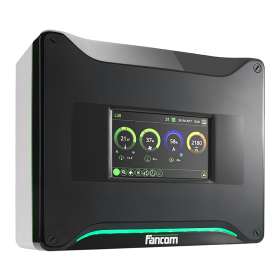
- Manuals
- Brands
- Fancom Manuals
- Control Systems
- LUMINA 38
- Instruction manual
-
Contents
-
Table of Contents
-
Bookmarks
Quick Links
Related Manuals for Fancom LUMINA 38
Summary of Contents for Fancom LUMINA 38
-
Page 2
N.B.: The original, authentic version of this manual is the English version produced by Fancom B.V. or one of its daughter companies (referred to further as Fancom). Any modifications introduced to this manual by third parties have neither been checked nor approved by Fancom. Modifications are taken by Fancom to include translations into languages other than English and the insertion and/or deletion of text and/or illustrations to/from the original contents. -
Page 3: Table Of Contents
Table of contents General introduction ……………………..1 Documentation with the control computer………………1 How to use this manual ……………………1 Fancom Sales & Service Center ………………… 2 F-Central FarmManager™ ………………….2 Explanation control functions ……………………3 Ventilation ……………………….3 Heating ……………………….12 Cooling ……………………….
-
Page 4
Lumina 38 Table of contents 10.4 FRM.8 ……………………….59 10.5 Connection FNet and I/O-net ………………….60 Appendix: EC declaration of conformity ………………..61… -
Page 5
Operation and safety instructions These subjects are covered in a separate manual. This manual also applies to other control computers in the Fancom F2000-line. Always read the safety instructions and warnings carefully before using the control computer. Always keep this manual close to the Lumina 38. -
Page 6: Fancom Sales & Service Center
For any questions and support, please contact the local Fancom Sales & Service Center. Virtually all Fancom equipment can be controlled and managed from a central location. This requires the F- Central FarmManager software package and a communication module. The screens in the control computers are…
-
Page 7
Lumina 38 Explanation control functions Please refer to the user’s manual for an explanation of the basic principles of climate management. This chapter describes the working of a number of specific control functions that the installer should set. Ventilation is used to create the most pleasant climate possible in the house. Ventilation also extracts harmful substances from the house and introduces fresh air into the house. -
Page 8
Lumina 38 Explanation control functions The control computer supports four types of house ventilation: • Cross: With side ventilation the house is ventilated on the side. One side is the air inlet, the other side the air outlet. The air flows across the house sideways. The inlet can be a minimum air inlet system or a natural curtain. -
Page 9
Lumina 38 Explanation control functions All controllable fans are always controlled at the same percentage. Figure 3: Example of a controllable fan with one extra controllable fan. Directly controlled by the (A) or by the relay (R) Extra fans can only be switched on or off via a relay. They are usually used when the controllable fans are running at maximum or in combination with controllable fans to achieve a gradual increase in ventilation. -
Page 10: Explanation Control Functions
Lumina 38 Explanation control functions The control computer determines the use of air inlets, extra inlets and fans based on the combi-table. Below is an example of a combi-table. This may differ to your own combi-table, for example, because you use a different number of extra fans.
-
Page 11
Lumina 38 Explanation control functions Example: Taking ventilation positions from the combi-table The required ventilation level on a certain day is 21%. The control computer uses the settings at position M3: • Controllable fans and the extra controllable fans: 25% activated. -
Page 12: Ventilation
Lumina 38 Explanation control functions The settings that have to be made for the tunnel part (T-part) correspond broadly with the settings for the M/MT- part. Instead of the ventilation position in % you enter the offset temperature for the positions. At the first position this offset temperature is linked to start temperature ventilation + calculated bandwidth.
-
Page 13
Modulating control allows minimum ventilation to be achieved using, for example, a large fan. Fancom differentiates between the following types of modulating control: • Modulating control with fixed modulation times •… -
Page 14
Lumina 38 Explanation control functions Linear controlled fans have a minimum ventilation level, for example 30%. This determines below what percentage the ventilation will modulate, and the ventilation level during modulating. If, for example, the calculated output of the linear part is 10%, ventilation will run for 10/30th of the cycle time at 30%, and not run for the rest of the time. -
Page 15
Lumina 38 Explanation control functions In order to ventilate the right amount of air and to have a perfect air distribution, it is possible to ‘pulse’ the air to the middle of the house for a fixed amount of time and then wait until the fresh air is nicely spread over the birds. -
Page 16: Heating
Lumina 38 Explanation control functions The fans which must activate at a certain ventilation position have been set in the relay or combi-table. However, this means that the same fans will always be active. Using rotating the control computer will activate the number of assigned fans, but in a different sequence each time.
-
Page 17
Lumina 38 Explanation control functions The control computer activates heating if the house Setpoint – temperature drops below hysteresis. If the house temperature rises, the heating will stay on until the control value heating is reached. A set Repeat time can be used to prevent unnecessary activation/deactivation of the heating. -
Page 18: Cooling
Lumina 38 Explanation control functions With analog heating control the heating is controlled by a P- or PI-control. Use Repeat time to determine the type of heating control. If the Repeat time is less than 10 seconds, a P-band control is concerned. In other cases PI- control applies.
-
Page 19: Humidifying
Lumina 38 Explanation control functions Time modulating ON/OFF control This type of control can be selected if the cooling capacity is large and the cooling system is suitable for modulating control. Cooling is continually on, if the temperature of the cooling control is higher than Setpoint + hysteresis.
-
Page 20: Humitemp
Lumina 38 Explanation control functions Example: Time modulating humidity control Inside Hysteresis the control computer controls humidity during a part of the Repeat time. The control computer calculates this on/off time as follows: • Setpoint: • Measured RH: • Hysteresis: •…
-
Page 21: Optisec
Lumina 38 Explanation control functions OptiSec = Optimum Setpoint Control The control computer uses a neutral zone, with minimum ventilation and no heating. This lowers energy costs. The neutral zone is the area between control value heating and start temperature ventilation. If OptiSec is not…
-
Page 22
Takes into account the following guidelines: Figure 7: required edge distances Never place the Lumina 38 in a place where the weather has direct influence (not in the sun, not in places where the temperature can rise sharply etc.). Never mount the Lumina 38 near water pipes, drainage pipes etc. -
Page 23
The Lumina 38 should be possible to shut down with a suitable double pole switch which is easily accessible. Connect the Lumina 38 to a group that is fused with 16A from the main distributor and mount the cables in separate cable trays. -
Page 24
Lumina 38 Installing the Lumina 38 The installer can configure the control computer using the installation menu. This menu also contains screens for standard system settings and diagnoses. To call up the installation menu: press the navigation keys UP and DOWN simultaneously for a few seconds. -
Page 25: System
Lumina 38 System SYSTEM → → tab page SYSTEM SYSTEM Common Clock type Setting of the 12 or 24 hour time indication. Time and Date Setting of the current time and date Computer name Setting of the name of the control computer.
-
Page 26
Lumina 38 System → → tab page SYSTEM SYSTEM Units Unit of measurement Setting to simultaneously set all units to METRIC or NON-METRIC. Use the + and – key on the alpha-numeric keyboard to change individual values. → → tab page… -
Page 27: Sd Card Menu
Lumina 38 System → → tab page SYSTEM SYSTEM Sharing Share animal data Setting for sending or receiving animal data. The control computers in the network can share data. In this way the animal data only has to be entered once, at the sender.
-
Page 28: Application
Lumina 38 System Data saved on one control computer can only be loaded into another control computer if both computers are of the same type. In addition, the set control computer numbers must be identical. If both these conditions are not met, loading will fail.
-
Page 29: Communication
Lumina 38 System C is a communication bus used to connect printed circuit boards in the control computer (e.g. AI.4). → → tab page SYSTEM COMMUNICATION Reset counters Setting used to reset all data to zero simultaneously. The IO-Net is a connection for intelligent network modules. For example, Intelligent Relay Modules (IRM), Intelligent Digital Modules (IDM) or Intelligent Sensor Modules (ISM).
-
Page 30
Lumina 38 System FNet is the Fancom Network. Several control computers can be linked via this network. FNet is also used to operate the connected control computers from a PC. → → tab page SYSTEM COMMUNICATION FNet Reset counters Setting used to reset all data to zero simultaneously. -
Page 31: Io Test
Lumina 38 System Use the Input (I) and Output (O) test menu to set the control computer to test the communication channels. In the IO-test menu inputs can be readout and outputs controlled at system level. → SYSTEM IO TEST The functions in the IO-test menu stop all the control actions of the control computer.
-
Page 32: House Setup
Lumina 38 House setup This chapter explains all the options in the HOUSE SETUP menu. HOUSE SETUP select the parts of the control computer you intend to use. The control computer will only display data relevant to you in the screens. Parts not used, will not be shown. Most codes are self explanatory.
-
Page 33
Lumina 38 House setup → tab page HOUSE SETUP Outside Measurement outside Setting indicating if outside temperature measurement is used. If outside temperature temp. measurement is used the outside temperature can influence a number of controls. Measurement outside Setting indicating if outside RH measurement is used. Using absolute moisture calculation, the control computer determines if the outside air is suitable for dehumidification. -
Page 34
Lumina 38 House setup Air inlet in use Setting indicating the number of air inlets to be used. Tunnel inlet in use Setting indicating the number of tunnel inlets to be used. Number of stages M/MT- Setting indicating the number of stages to be used in the combi-table. -
Page 35
Lumina 38 House setup Water clock Setting indicating the number of water clocks to be used. Water registration Setting indicating if water registration is used. Extra clock Setting indicating if extra clocks are used. → tab page HOUSE SETUP User Apply temperature curve Setting indicating if the house temperature is to be controlled based on the curve. -
Page 36
Lumina 38 House setup Night correction Setting indicating if a setpoint correction is required during the dark period (night time) of the day. Linked to Setting indicating which light clock is used to determine the dark period times. → tab page →… -
Page 37
Lumina 38 House setup → tab page HOUSE SETUP OptiSec Band Setting of the maximum correction (Band). The control computer can increase the setpoint heating until this equals the setpoint house temperature. Delay Setting of the Delay to minimise the influence of temperature fluctuations. -
Page 38: Installer
Lumina 38 Installer This chapter explains all the options in the INSTALLER menu. In the combi-table the relationship between ventilation and air inlets for the entire ventilation course is entered. For more information about the combi-table, see “Combi-table page 5”.
-
Page 39
Lumina 38 Installer Con. The entry depends on the system setting M/MT-part HOUSE SETUP, tab page Con. Extra Mod. % Combi: • Con. Enter the positions of the linear controllable fans. • Con. Extra (This column is only active if extra fans are used in the controllable part) -
Page 40
Lumina 38 Installer → → → → tab page INSTALLER VENTILATION COMBI MTT M/MT-phase(min) Cap. Position % Setting of the ventilation percentage at which fans should activate/deactivate and air inlets open/close. The ventilation percentages must increase from the lowest to the highest position. -
Page 41
Lumina 38 Installer → → → tab page INSTALLER VENTILATION SETTINGS Miscell. When using T-inlets, the house sizes are required to be able to calculate the airspeed during T-phase. House length Setting of the length of the house. House width Setting of the width of the house. -
Page 42
Lumina 38 Installer → → → tab page INSTALLER VENTILATION SETTINGS M/MT-Part Description Setting of the name of the function. Output address Setting of the analog output address. Analog type Setting indicating the analog control type Extra analog Setting of the analog output address. -
Page 43
Lumina 38 Installer Modulating: FIXED TIME Modulate under % Setting of the ventilation percentage, below which the control computer will apply modulating control to the linearly controlled part. This applies to fans that cannot be controlled below this percentage. Linearly controllable fans usually have a minimum ventilation level. -
Page 44
Lumina 38 Installer → → → tab page INSTALLER VENTILATION SETTINGS Relay Rotation time Setting of the period after which the relays rotate. Output address Setting of the combi relay addresses. Rotate Setting indicating if fans, controlled by the combi-relays, rotate in a certain sequence. -
Page 45: Ventilation
Lumina 38 Installer → → → tab page INSTALLER VENTILATION INLETS Inlet Description Setting of the name of the function. Temp. inputs Setting the addresses of the analog inputs. If the temperature sensors have not been assigned, the control computer will use the house temperature.
-
Page 46
Lumina 38 Installer Output address Setting of the analog output address. Analog type Setting indicating the analog control type Pre-run time Setting of the time in which the air inlets go to the required position, before the fans activate. Setting indicating if these air inlets are to be included in modulating ventilation — if Modulate link modulating ventilation is used. -
Page 47
Lumina 38 Installer → INSTALLER COOLING Description Setting of the name of the function. Temp. inputs Setting the addresses of the analog inputs. If the temperature sensors have not been assigned, the control computer will use the house temperature. Control… -
Page 48
Lumina 38 Installer In the clocks and registration menu enter the settings for the clocks used per house. In the menu HOUSE SETUP the clocks to be used have already been entered. The data for these clocks can be set here. -
Page 49
Lumina 38 Installer The water clock controls the water supply in the house. 11 clocks can be used per house (1 central clock and 10 clocks for each water line). You only need to set the central clock settings (Reg-02). The settings for each water line will be assigned automatically. -
Page 50
Lumina 38 Installer Description Setting of the name of the function. Time clock type Setting indicating how the user can use the clock: • ON/OFF: User enters on/off times. • ON/DURATION: User enters time and duration of activation. Time clock relay… -
Page 51: Registration
Lumina 38 Installer Control on Setting of the way in which light is controlled. This option is only available if light measurement=YES has been selected at light clocks. • LUX: If you want to control the light using a light sensor, select LUX. The light clock will adjust the light intensity to the measured light intensity.
-
Page 52: Inside Climate
Lumina 38 Installer Reg. Input Setting the type of measurement: • MANUALLY: Enables you to enter the amount of today manually. • SLOW PULSE: Measuring instruments with a maximum frequency of 20 pulses per second (20 Hz). • QUICK PULSE: Measuring instruments with a maximum frequency of 20 pulses per second (20 Hz) (only use when there is a link with a switch clock).
-
Page 53
Lumina 38 Installer Speed press. contr. Setting of the speed at which the control computer determines influences (SLOW MODERATE / FAST). Input <x> measurement Setting the address of the analog input. where x is RH, NH3 or Speed <x> control… -
Page 54
Lumina 38 Installer Type wind measure Setting of the type of anemometer used. Fancom uses the following types of weather meters: • GREEN_2P (default) • BLACK_4P • BLACK_2P • DAVIS • By choosing the required type and assigning the correct inputs, the control computer will automatically make all corresponding settings. -
Page 55: External Alarm
Lumina 38 External alarm The control computer can connect to external alarm contacts and respond appropriately. EXTERN.ALARM Description Setting of the name of the function. Input address Setting of the address of the digital input. The readout of the input value is between brackets.
-
Page 56: Basic Principle Thermo Differential
Lumina 38 Basic principle thermo differential An extreme rise in house temperature can be caused by fire. In such a case, it is important that an alarm is raised quickly. The sensors (assigned to the house temperature) in the zones can detect sudden rises in temperature. A sensor issues an alarm if: •…
-
Page 57
Lumina 38 Basic principle thermo differential Relais type Setting of the passive (not controlled) relay status. • N.O. (normally open) if it makes no contact. • N.C. (normally closed) if it makes contact. Alarm type Setting for the way in which the alarm will be processed. -
Page 58: Inputs And Outputs
Lumina 38 Inputs and outputs When controls are assigned, the I/O settings are filled in automatically. When Fancom equipment is used these settings will normally ensure correct control. These settings can be adjusted using the zoom function ( The input and output settings can be readout, and changed in the INPUT / OUTPUT menu. However, we advise you not to make changes here but to do these changes in the setup screens.
-
Page 59
Lumina 38 Inputs and outputs Type Setting of the type of measurement being carried out: • NONE • TEMPERATURE • CO2 3000 PP • CO2 30000 PP • LINEAR (U) • LINEAR (R) • POLYNOMIAL (U) • LUX (R) Measurement The measured signal (if changed manually, the correction value is adjusted accordingly). -
Page 60
Lumina 38 Inputs and outputs Min.jump…max The control range of the analog output. Enter the minimum and maximum jump (in %). Actual value Shows the actual value of the control voltage of the analog output. Digital outputs have the following settings: Output address The address of the output. -
Page 61: Digital Inputs
Relay: make-and-break contact, voltage free Max. 2A 60Vdc/30Vac Communication I/O-Net for extra inputs and outputs using I/O-modules. FNet, Fancom network for intercommunication of control computers and PC connection. FRM.8 8 Digital outputs (relays) Relay 1, 3, 5, 7: make-and-break contact Max.
-
Page 62
Lumina 38 Technical specifications Touch screen HI mainboard LED strip FUNC (CPU) IOB.12 (I/O) Power supply Internal relays (2x FRM.8) -
Page 63
Lumina 38 Technical specifications AI type Type analog input • Voltage measurement (U: • Resistance measurement (R: 6 Analog outputs 12 Analog inputs 8 Digital inputs 2×8 digital outputs… -
Page 64
The control computer and the second I/O network module require a terminal resistor. The first I/O network module is looped. This does not require a terminal resistor. The Fancom Greenlink cable (UTP 1x2x0.8mm, unshielded twisted pair) used to wire the FNET and I/O net. Maximum cable length = 1200 meters. -
Page 65
Lumina 38 Appendix: EC declaration of conformity Manufacturer Fancom B.V. Address: Industrieterrein 34 Place: Panningen (the Netherlands) Hereby declares that: Lumina 38 Satisfies the conditions of: The Low Voltage Directive 2014/35/EU according to EN-61010 the EMC Guideline, directive 2014/30/EU Emission and immunity according to NEN-EN-IEC 61326…
Компьютер Lumina 38 / F38 (старая версия) Fancom
Автоматическая регулировка параметров приточного и отработанного воздуха и системы отопления с помощью компьютера Lumina 38.
Мощность системы микроклимата индивидуально подбирается и конфигурируется в зависимости от требований. Множество локальных датчиков создают во всем корпусе не только комфортный и равномерный микроклимат, стимулирующий рост животных, но и дают возможность делить корпус на разные климатические зоны
Lumina 38 может использоваться в птичниках следующих типов:
- Птичники для несушек
- Птичники для молодняка
- Птичники для молодняка кур-несушек
- Бройлерники
- Индюшатники
Lumina 38 отлично подходит для регулирования климата в MTT-помещении. Аббревиатура MTT означает Минимальная / Промежуточная / Туннельная. Используя данную концепцию, компьютер постепенно увеличивает вентиляцию с минимальной до туннельной вентиляции. Использование туннельной вентиляции при теплом климате, таком как на Ближнем Востоке или в Азии. Однако туннельная вентиляция может также использоваться при умеренном или холодном климате для предупреждения падежа во время жаркой погоды. Благодаря МТТ-концепции компании Fancom переход от минимальной к туннельной вентиляции осуществляется постепенно. Дополнительные затраты на туннельную вентиляцию (в сравнении с другими системами) незначительны благодаря эффективному использованию оборудования.


Технические характеристики компьютер Lumina 38 / F38

Запчасти к LUMINA 38 TOUCH / F38 FANCOM — компьютер управления микроклиматом:
| Артикул | Наименование | |
 |
A1471009.05 | HI BASIC A2 PROGRAMMED |
 |
A1471022 | LED BOARD 360 |
 |
A1471032 | HI+ BOARD A2 |
 |
A1541022.05 | DISPLAY 240X320 LED W. TESTED |
 |
A1541032.05 | DISPL.COLOR 7 + CARRIER |
 |
A1755039 | IOB.12 BOARD B1.1 |
| A1755051.05 | SBC LUMINA AM3354-1000C+PROGR. | |
| A1755051.07 | SBC LUM.AM3354-1000C+PR.L.LNX | |
| A2431070 | PS 24V+5VDC 50W + CARRIER | |
| A3470066.05 | FRM.8 BOARD A0 TESTED | |
| A3470073 | K360 BOARD A1.0-2 9.5MM BUTTON | |
| A3470128 | DISPLAY 240X320 LED WHITE + HI | |
| A3739022 | FLAT CABLE + CON. 20P 70MM | |
| A3739023 | FLAT CABLE + CON. 20P 200MM | |
| A3739024 | FLAT CABLE + CON. 10P 260MM | |
| A3739026 | FLAT CABLE + CON. 10P 150MM | |
| A3799025 | COVER WITH GLASS 360 | |
| A3851015 | CABLE TREE P. SUPP F2000 550MM | |
| A3851016 | CABLE TREE POWER SUPPLY | |
| A5105085 | FUNC BOARD UNPROTECTED + F2KU | |
| A7859025 | COVER 360 LUMINA TOUCH | |
| A7859025.02 | COVER 360 LUMINA TOUCH LNX |
(Ocr-Read Summary of Contents of some pages of the Fancom LUMINA 38 Document (Main Content), UPD: 20 April 2023)
-
21, Lumina 38 Explanation control functions 17 OptiSec = Optimum Setpoint Control The control computer uses a neutral zone, with minimum ventilation and no heating. This lowers energy costs. The neutral zone is the area between control value heating and start temperature ventilation. If OptiSec is not used, the control value heating is lower than setpoint house temperature. With very young animals the actual house temperature can be lower than the setpoint house tem…
-
32, Lumina 38 House setup 28 This chapter explains all the options in the HOUSE SETUP menu. In HOUSE SETUP select the parts of the control computer you intend to use. The control computer will only display data relevant to you in the screens. Parts not used, will not be shown. Most codes are self explanatory. HOUSE SETUP → tab page Inside Heating Setting of the number of heating units to be used. Cooling Setting of the number of c…
-
63, Lumina 38 Technical specifications 59 AI type Type analog input • Voltage measurement (U: ) • Resistance measurement (R: ) AO 6 Analog outputs AI 12 Analog inputs DI 8 Digital inputs DO 2×8 digital outputs
… -
56, Lumina 38 Basic principle thermo differential 52 An extreme rise in house temperature can be caused by fire. In such a case, it is important that an alarm is raised quickly. The sensors (assigned to the house temperature) in the zones can detect sudden rises in temperature. A sensor issues an alarm if: • It measures a temperature above 58°C; • The maximum temperature increase is exceeded (e.g. an increase of 5°C within 2 minutes). The control computer monitors …
-
18, Lumina 38 Explanation control functions 14 With analog heating control the heating is controlled by a P- or PI-control. Use Repeat time to determine the type of heating control. If the Repeat time is less than 10 seconds, a P-band control is concerned. In other cases PI- control applies. P-control If the temperature is higher than the Control value, heating is on the mini…
-
20, Lumina 38 Explanation control functions 16 Example: Time modulating humidity control Inside Hysteresis the control computer controls humidity during a part of the Repeat time. The control computer calculates this on/off time as follows: • Setpoint: 80% • Measured RH: 75% • Hysteresis: 10% • Repeat time: 100 sec. The humidity relay will repeatedly be on for 50 seconds and off for 50 seconds. H…
-
39, Lumina 38 Installer 35 Con. / Con. Extra / Mod. % The entry depends on the system setting M/MT-part in HOUSE SETUP, tab page Combi: • Con. Enter the positions of the linear controllable fans. • Con. Extra (This column is only active if extra fans are used in the controllable part) Control of extra fan Settings: Position 0-R for relay Setting: Position 0-A for linear • Mod. % (This column …
-
47, Lumina 38 Installer 43 INSTALLER → COOLING Description Setting of the name of the function. Temp. inputs Setting the addresses of the analog inputs. If the temperature sensors have not been assigned, the control computer will use the house temperature. Control Setting of the heating control type: LINEAR or RELAY. Output address Setting of the analog output address (choice LINEAR control) or relay output (choice RELAY c…
-
4, Lumina 38 Table of contents ii 10.4 FRM.8 …………………………………………………………………………………………………………………………. 59 10.5 Connection FNet and I/O-net ………………………………………………………………………………………….. 60 11. Appendix: EC declaration of conformity …………………………………
-
22, Lumina 38 Installing the Lumina 38 18 Takes into account the following guidelines: Figure 7: required edge distances Never place the Lumina 38 in a place where the weather has direct influence (not in the sun, not in places where the temperature can rise sharply etc.). Never mount the Lumina 38 near water pipes, drainage pipes etc. Never mount the Lumina 38 in a humid and/or dusty room and certainly not in the room where …
-
16, Fancom LUMINA 38 Lumina 38 Explanation control functions 12 The fans which must activate at a certain ventilation position have been set in the relay or combi-table. However, this means that the same fans will always be active. Using rotating the control computer will activate the number of assigned fans, but in a different sequence each time. This creates an optimal spread of air in the house. In addition, all fans are evenly used. R…
-
44, Lumina 38 Installer 40 INSTALLER → VENTILATION → SETTINGS → tab page Relay Rotation time Setting of the period after which the relays rotate. Output address Setting of the combi relay addresses. Rotate Setting indicating if fans, controlled by the combi-relays, rotate in a certain sequence. INSTALLER → VENTILATION → SETTINGS → tab page Imago Description Setting of the name of the function. O…
-
53, Lumina 38 Installer 49 Speed press. contr. Setting of the speed at which the control computer determines influences (SLOW / MODERATE / FAST). Input <x> measurement where x is RH, NH3 or CO2 Setting the address of the analog input. Speed <x> control where x is RH, NH3 or CO2 Setting of the speed at which the control computer determines influences (SLOW / MODERATE / FAST). T…
-
13, Fancom LUMINA 38 Lumina 38 Explanation control functions 9 Ventilation Exhaust Inlets Position MOD Extra fans Relay (0-1-M) Cap. Inlet Extra Pres- sure % % 1 2 3 4 5 m3/h % % Pa M1 1 1 M 0 0 0 0 200 1 0 0 M2 20 100 M 0 0 0 0 20000 20 0 0 M3 21 50 M M 0 0 0 21000 21 0 0 M4 39 99 M M 0 0 0 39000 39 0 0 M5 40 100 1 1 0 0 0 …
-
28, Lumina 38 System 24 Data saved on one control computer can only be loaded into another control computer if both computers are of the same type. In addition, the set control computer numbers must be identical. If both these conditions are not met, loading will fail. Backup FUNC Backup FUNC writes a copy of the operating system (type .FIN) from the control computer to the SD-card. Update FUNC Update FUNC l…
-
33, Fancom LUMINA 38 Lumina 38 House setup 29 HOUSE SETUP → tab page Outside Measurement outside temp. Setting indicating if outside temperature measurement is used. If outside temperature measurement is used the outside temperature can influence a number of controls. Measurement outside RH Setting indicating if outside RH measurement is used. Using absolute moisture calculation, the control computer determines…
-
57, Lumina 38 Basic principle thermo differential 53 Relais type Setting of the passive (not controlled) relay status. • N.O. (normally open) if it makes no contact. • N.C. (normally closed) if it makes contact. Alarm type Setting for the way in which the alarm will be processed. • LOUD: Loud alarm (switch the alarm relay). • SILENT: Silent alarm. Reset Button for …
-
24, Lumina 38 Installing the Lumina 38 20 The installer can configure the control computer using the installation menu. This menu also contains screens for standard system settings and diagnoses. To call up the installation menu: press the navigation keys UP and DOWN simultaneously for a few seconds. The following installation menu will appear: Follow the steps below to install …
-
7, Fancom LUMINA 38 Lumina 38 Explanation control functions 3 Please refer to the user’s manual for an explanation of the basic principles of climate management. This chapter describes the working of a number of specific control functions that the installer should set. Ventilation is used to create the most pleasant climate possible in the house. Ventilation also extracts harmful substances from the house and introduces fresh air into the…
Popular Documents:
LUMINA 16, Aura 14, I-FAN MODULAR
| # | File/Document | Type | Device | Pages | File MB | |
|---|---|---|---|---|---|---|
| 1 | Fancom IMS Control Systems | Control Systems | IMS | 64 | — | |
| 2 | Fancom LM.125 Controller | Controller | LM.125 | 67 | — | |
| 3 | Fancom LUMINA 16 Desktop | Desktop | LUMINA 16 | 67 | — | |
| 4 | Fancom FB.1 Control Systems | Control Systems | FB.1 | 66 | — | |
| 5 | Fancom Aura 14 Controller | Controller | Aura 14 | 44 | — | |
| 6 | Fancom MRK.1 Control Unit | Control Unit | MRK.1 | 23 | — | |
| 7 | Fancom Milan-Touch Touch terminals | Touch terminals | Milan-Touch | 25 | — | |
| 8 | Fancom IMS Control Unit | Control Unit | IMS | 24 | — | |
| 9 | Fancom I-FAN MODULAR Fan | Fan | I-FAN MODULAR | 83 | — | |
| 10 | Fancom MRK.2 Control Systems | Control Systems | MRK.2 | 33 | — |