-
Contents
-
Table of Contents
-
Bookmarks
Quick Links
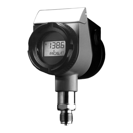
dTRANS p02
Pressure Transmitter
B 40.4385
Operating Instructions
07.01/00365643
Related Manuals for JUMO dTRANS p02
Summary of Contents for JUMO dTRANS p02
-
Page 1
Pressure Transmitter B 40.4385 Operating Instructions 07.01/00365643… -
Page 3: Table Of Contents
Contents Typographical conventions __________________________ 4 Warnings ____________________________________________________ 4 Note signs ___________________________________________________ 4 General ____________________________________________ 5 Preface _____________________________________________________ 5 Application __________________________________________________ 6 Delivery package ___________________________________ 7 Instrument identification _____________________________ 8 Nameplate __________________________________________________ 8 Type designation _____________________________________________ 9 Dimensions/details __________________________________________ 10 Dimensions: «non-flush pressure connections» __________________ 10 Dimensions: «flush pressure connections»…
-
Page 4
Contents Commissioning ____________________________________ 23 Characteristic _______________________________________________ 23 Self-test ____________________________________________________ 24 Measuring the absolute pressure ______________________________ 26 Measuring the gauge pressure ________________________________ 29 Adjustment options ________________________________ 32 The level concept ___________________________________________ 32 Sequence for keypad operation _______________________________ 33 Display level ________________________________________________ 34 Parameter level _____________________________________________ 35 Detailed explanations ________________________________________ 38 Opening the instrument ____________________________ 41… -
Page 6: Typographical Conventions
1 Typographical conventions Warnings Danger This sign is used when there may be danger to personnel if the instructions are disregarded or not followed accurately! Caution This sign is used when there may be damage to equipment or data if the instructions are disregarded or not followed accurately! Note signs Note…
-
Page 7: General
2 General Preface Please read these Operating Instructions before commissioning the instru- ment. Keep the manual in a place which is accessible to all users at all times. Please assist us to improve these operating instructions where necessary. Your suggestions are welcome. Phone Germany (0661) 6003-714 abroad…
-
Page 8: Application
2 General Application General The type JUMO dTRANS p02 is used to measure the pressure of corrosive and non-corrosive gases, vapors and liquids. The pressure transmitter uses the piezo-resistive effect to make the measurement. The output signal is a pro- portional DC current which is linearly proportional to the input pressure.
-
Page 9: Delivery Package
If this calibration certificate is lost, or should you need an additional one, it can be ordered from JUMO stating the serial No. of the pressure transmitter (see nameplate), see addresses of suppliers on the back of the operating instructions…
-
Page 10: Instrument Identification
4 Instrument identification Nameplate Nameplate on a pressure transmitter without approval for use within the hazardous (Ex) area. Nameplate on a pressure transmitter with approval for use within the hazard- ous (Ex) area.
-
Page 11: Type Designation
4 Instrument identification Type designation (1) Basic type 404385 pressure transmitter dTRANS p02 with sensing element in piezo-resistive or thin-film technology (2) Basic type extensions none Protection EEx ia IIC (PTB 98 ATEX 2194) for increased temperature of medium up to 200°C…
-
Page 12: Dimensions/Details
4 Instrument identification Dimensions/details G 1/2 (10) G 1/2 NTS 527 Cover for electrical connection Electrical connection, M 20×1.5 cable gland PE connection Blanking plug (electrical connection or instrument mounting possible) Cover flap (keypad underneath) Electrical connection, Harting connector Han 7D / Han 8D (8U) Bezel LCD display Process connection…
-
Page 13: Dimensions: «Flush Pressure Connections
4 Instrument identification Dimensions: «flush pressure connections» 604 / 606 604 / 606 taper connection with slotted ring nut Kegelstutzen mit Nutüberwurfmutter 613 / 616 to DIN 11 851 613 / 616 nach DIN 11 851 to DIN 32 676 nach DIN 32 676 32 a/f SW 32…
-
Page 14: Instrument Description
5 Instrument description Technical data 5.1.1 For pressure transmitters without intrinsic safety Range Start and end of range can be adjusted continuously within the measuring range. The measuring span should not go below 10% of the nominal range. Chapter 4.1 «Nameplate», page 8; For setting the measurement start or span: «Measurement start, blind setting», page 38 «Measurement span, blind setting», page 38…
-
Page 15
5 Instrument description 5.1.2 For pressure transmitters with intrinsic safety Explosion EEx ia IIC T4—T6, to EN 50 014 and EN 50020 (CENELEC) protection EC Type- PTB 98 ATEX 2194 Examination Certificate Permissible Temperature class ambient temperature +85°C +75°C +60°C… -
Page 16: Mounting
General Open cover flap The cover flap can be opened with a coin. The keys for operating the JUMO dTRANS p02 are underneath the cover flap. For details on the setting options see: «The level concept», page 32ff. List of Affix one of the enclosed lists of functions to the cover flap.
-
Page 17: Mounting By The Pressure Connection
6 Mounting Operating The normal operating position of the JUMO dTRANS p02 pressure transmitter position is vertically upright. Depending on the conditions of the measurement site, the pressure transmit- ter can also be mounted in a different orientation. In accordance with the required operating position, the LCD can be rotated in 90°…
-
Page 18: Pressure Connection
6 Mounting Pressure connection Seals Seals to EN 837 or DIN 16 258 may be used. Tightening 200 Nm max. torque The correct tightening torque depends on the size, material and shape of the seal that is used, as well as on the pressure connection of the pressure trans- mitter.
-
Page 19: Installation
7 Installation Electrical connection Earth the instrument! TEST HART Unscrew the cover from the housing «Unscrewing the bezel ring or housing cover», page 41. General notes — cable diameter 6 to 12 mm — conductor cross-section up to 1.5mm — route signal lines separately from cables with voltages above 60 V — use shielded cables with twisted cores — avoid the neighborhood of large electrical systems …
-
Page 20
7 Installation Connection Terminals Screw terminals Assignment Supply 1 L+ 1 L+ 11.5 — 36 V DC 2 L- 2 L- 11.5 — 30 V DC for intrinsically safe version Output 1 L+ 1 L+ 4 — 20 mA 2-wire 2 L- 2 L- proportional current 4 to 20 mA in supply… -
Page 21: Testing The Output Signal
Test connection via faston connectors 2.8 x 0.8 mm or test termi- nals. ® Connection of a HART modem Supply voltage Pressure transmitter Burden up to 15 transmitters 11.5 — 36 V DC JUMO dTRANS p02 (multidrop mode) ® HART modem PC or note- book Setup program RS-232-C Burden ≤…
-
Page 22: Connection Of A Hart® Communicator
® Connection of a HART communicator Pressure transmitter up to 15 transmitters Burden Supply voltage 11.5 — 36 V DC JUMO dTRANS p02 (multidrop mode) ® HART communicator Burden ≤ (U — 11.5 V) / 0.022 A ® min. 250 Ω , max. 1100 Ω…
-
Page 23: Electrical Connection In The Hazardous (Ex) Area
7 Installation Electrical connection in the hazardous (Ex) area General The appropriate regulations must be observed when making the electrical connection; inside the area with an explosion hazard this is, in particular: — the regulations concerning electrical equipment in areas with an explosion hazard (Elex V) — the regulation for the installation of electrical equipment in areas with an explosion hazard EN 60 079-14:1997 (VDE 0165)
-
Page 24
7 Installation PE connection For operating the pressure transmitter in the Ex area, it must be earthed via the external ground terminal. In addition, the ground terminal inside the housing can be used to connect the cable shielding. -
Page 25: Commissioning
8 Commissioning Characteristic Output signal Example: and display Nominal range 0 — 600 mbar. Range setting 50 — 450 mbar. Output current [mA] Fault current Saturation Saturation Fault current (21.5 or 3.85) (low) (high) (21.5 or 3.85) 21.50 20.00 4.00 Pressure 3.85 [mbar]…
-
Page 26: Self-Test
8 Commissioning Self-test Active After the supply has been switched on, the pressure transmitter carries out a self-test. If the result of the self-test is positive, the display that was most recently selected at the display level will be shown after approx. 20 seconds (on new pressure transmitters, the display “pressure with unit”).
-
Page 27
8 Commissioning Error On over/underrange, an error signal appears, see below «Trouble-shooting», page 43. -
Page 28: Measuring The Absolute Pressure
8 Commissioning Measuring the absolute pressure Gases Transmitter below Transmitter above the pressure tapping the pressure tapping (exception) (standard arrangement) (1) Transmitter (2) Shut-off fitting 2A shut-off valve to process 2B shut-off valve for test connection (3) Pressure line (4) Shut-off valve (5) Shut-off valve (6) Condensation vessel (7) Purge valve…
-
Page 29
8 Commissioning Vapors (1) Transmitter (2) Shut-off fitting 2A shut-off valve to process 2B shut-off valve for test connection (3) Pressure line (4) Shut-off valve (5) Blow-down valve (8) Pressure equalization reservoir Pressure Initial state: all valves closed. application Operate the shut-off fittings in the following order: Open shut-off valve (4) at the pressure tapping. -
Page 30
8 Commissioning Liquids (1) Transmitter (2) Shut-off fitting 2A shut-off valve to process 2B shut-off valve for test connection (3) Pressure line (4) Shut-off valve (5) Blow-down valve Pressure Initial state: all valves closed application Operate the shut-off fittings in the following order: Open shut-off valve (4) at the pressure tapping. -
Page 31: Measuring The Gauge Pressure
8 Commissioning Measuring the gauge pressure Gases Transmitter above Transmitter below the pressure tapping the pressure tapping (standard arrangement) (exception) (1) Transmitter (3) Pressure line (2) Shut-off fitting (4) Shut-off valve 2A shut-off valve to process (5) Shut-off valve 2B shut-off valve for test connection (7) Condensation vessel or vent screw (8) Purge valve…
-
Page 32
8 Commissioning Vapors (1) Transmitter (2) Shut-off fitting 2A shut-off fitting to process 2B shut-off fitting for test connection or vent screw (3) Pressure line (4) Shut-off valve (6) Blow-down valve (9) Pressure equalization reservoir Pressure Initial state: all valves closed application Operate the shut-off fittings in the following order: Open shut-off valve (2B). -
Page 33
8 Commissioning Liquids (1) Transmitter (2) Shut-off fitting 2A shut-off valve to process 2B shut-off valve for test connection or vent screw (3) Pressure line (4) Shut-off valve (6) Blow-down valve Pressure Initial state: all valves closed application Operate shut-off fitting in the following order: Open shut-off valve (2B). -
Page 34: Adjustment Options
Two levels In order to make the operation of the pressure transmitter simple and transpar- ant, the functions of the JUMO dTRANS p02 have been divided into two lev- els. Both levels can be accessed from the keypad of the transmitter.
-
Page 35: Sequence For Keypad Operation
9 Adjustment options Sequence for keypad operation Layout Display level Parameter level after complete run or press «P» key for > 3 sec or pause for > 120 sec (Pmin) Reset Pressure min. pressure with dim. unit (P7) > 1 s (Pmax) Zero adjustment…
-
Page 36: Display Level
9 Adjustment options Display level After switching on the pressure transmitter, the last display that was selected will be shown at the display level. Sequence Action Function Display (Example) Display of pressure with dimensional unit Display of pressure value and sensor temperature in the units selected Display of the stored maximum pressure…
-
Page 37: Parameter Level
9 Adjustment options Parameter level Action Function Display Possible with keys «Detailed expla- (Example) setting nations», page 38ff. Reset the stored reset «Peak-reading minimum pointer», page 38. > 2 pressure > 1 seconds second Reset the stored reset «Peak-reading maximum pointer», page 38.
-
Page 38
9 Adjustment options Action Function Display Possible with keys «Detailed expla- (Example) setting nations», page 38ff. Display or set -110% to +110% «Measurement oder measurement start, blind set- start -10 to +110% ting», page 38. > 1 (blind setting) of nominal second range Display or set… -
Page 39
9 Adjustment options Action Function Display Possible with keys «Detailed expla- (Example) setting nations», page 38ff. Display and «Keys inhibi- oder set key inhibit no inhibit ted», page 39. > 1 all inhibited second LALL: all inhibited (adjustable via setup program only) all inhibited except… -
Page 40: Detailed Explanations
9 Adjustment options Detailed explanations Peak-reading Minimum and maximum pressures are saved. Both values can be individually pointer displayed and deleted. If the damping is set to 0 .0sec, minimum and maximum pressures will not be saved. «Detailed explanations», page 38. If the damping is 0.0sec, or after a reset of the display, “- — — — -”…
-
Page 41
9 Adjustment options Example 2: Nominal range: 0—600mbar Range required: -300 to +300mbar Measurement start: -50% Span: 100% Zero When a zero adjustment is made, the transmitter display is set to 0.000. The adjustment preset measurement start remains unaffected. Setting the measurement start: «Output current, measurement start and end», page 38. -
Page 42
9 Adjustment options Characteristics Output current Starting point linear Pressure [%] (a) = Lin = linear (b) = SLin = square root, linear up to Starting point starting point (c) = SoFF = square root, switched off up to starting point Instrument Display format: xx.yy version… -
Page 43: Opening The Instrument
10 Opening the instrument 10.1 Unscrewing the bezel ring or housing cover The bezel ring and the rear housing cover can be unscrewed. (1) Housing cover (2) Bezel ring Open with a screwdriver Close by hand without any tools…
-
Page 44: Rotating The Instrument
11 Rotating the instrument 11.1 Rotating Rotating the Depending on the operating position required, the LCD display can be rotated LCD display in steps of 90°. Unscrew the bezel ring. «Unscrewing the bezel ring or housing cover», page 41. Use a small-bladed screwdriver to carefully push out the catch of the LCD fixing and lever out the display board.
-
Page 45: Maintenance
12 Maintenance 12.1 Trouble-shooting Error/fault Possible cause Remedy Display: none no supply voltage switch on supply instrument faulty send instrument to supplier for repair Display: overrange, bring pressure back to within excessive pressure range, or adjust range Display: underrange, bring pressure back to within pressure too low range, or adjust range Display:…
-
Page 46
12 Maintenance Display: span too small increase span (at least 5%) «Measurement start, blind set- ting», page 38. instrument faulty send instrument to supplier for repair key not responding instrument faulty send instrument to supplier for repair keys inhibited reset key inhibit «Keys inhibited», page 39. -
Page 47
12 Maintenance… -
Page 48: Appendix
13 Appendix 13.1 EC Type-Examination Certificate…
-
Page 49
Equipment and Protective Systems Intended for Use in Potentially Explosive Atmospheres – Directive 94/9/EC EC Type-Examination Certificate Number: PTB 98 ATEX 2194 Equipment: Pressure transmitter Type dTRANS p02 Manufacturer: M. K. JUCHHEIM GmbH & Co. Address: Moltkestraße 13/31, D-36039 Fulda, Germany This equipment and any acceptable variation thereto are specified in the schedule to this Type-Examination Certificate. -
Page 50
13 Appendix… -
Page 51
EC Type-Examination Certificate PTB 98 ATEX 2194 (15) Description of equipment The pressure transmitter Type dTRANS p02 is used to convert a physical measurement variable into a standard electrical signal. The transmitter is intended for use in potentially explosive atmospheres. -
Page 52
13 Appendix… -
Page 53
13 Appendix Translation: Physikalisch-Technische Bundesanstalt Braunschweig and Berlin Schedule to EC Type-Examination Certificate PTB 98 ATEX 2194 (17) Special conditions not applicable (18) Essential health and safety requirements are assured by compliance with the standards cited above Zertifizierungsstelle Explosionsschutz (Certifying Body for Explosion Protection) signed Brunswick, 11 December 1998 Dr.-Ing. -
Page 54: Supplement To Ec Type-Examination Certificate
13 Appendix 13.2 Supplement to EC Type-Examination Certificate…
-
Page 55
D-36039 Fulda, Germany Description of additions and alterations The pressure transmitter Type dTRANS p02 will in future be manufactured and operated in accordance with the test documentation listed in the test report. The alterations concern the internal and external construction, for the introduction of other equipment variations, as well as to the “Electrical data”… -
Page 56
13 Appendix… -
Page 57
13 Appendix Translation: Physikalisch-Technische Bundesanstalt Braunschweig and Berlin Supplement 1 to EC Type-Examination Certificate PTB 98 ATEX 2194 Test and examination report: PTB Ex 01-20368 Zertifizierungsstelle Explosionsschutz Brunswick, 5 April 2001 (Certifying Body for Explosion Protection) signed (stamp) Dr.-Ing. U. Gerlach Page 2/2 EC Type-Examination Certificates are not valid without signature and stamp. -
Page 58: Eu Declaration Of Conformity Atex
13 Appendix 13.3 EU Declaration of Conformity ATEX…
-
Page 59
36039 Fulda, Germany Product designation: Data Sheet No. 40.4385 Type (series) dTRANS p02 404385/… We declare in sole responsibility that the product described fulfills the safety requirements of the European Directive 94/9/EC. The essential health and safety requirements are fulfilled through the compliance with the following… -
Page 60: Settings
13 Appendix 13.4 Settings Individual settings can be recorded in this table. Function LCD display Factory Customer’s setting setting Min. value (peak-reading pointer) P min –– not adjustable Max. value (peak-reading pointer) P max –– not adjustable Density correction 1.000 Dimensional unit or mbar Measurement start…
-
Page 64
M. K. JUCHHEIM GmbH & Co JUMO Instrument Co. Ltd. JUMO PROCESS CONTROL INC. Street address: JUMO House 885 Fox Chase, Suite 103 Moltkestraße 13 — 31 Temple Bank, Riverway Coatesville, PA 19320, USA 36039 Fulda, Germany Harlow, Essex CM20 2TT, UK…
-
Page 1
All manuals and user guides at all-guides.com dTRANS p02 Pressure Transmitter B 40.4385 Operating Instructions 07.01/00365643… -
Page 2
All manuals and user guides at all-guides.com… -
Page 3: Table Of Contents
All manuals and user guides at all-guides.com Contents Typographical conventions __________________________ 4 Warnings ____________________________________________________ 4 Note signs ___________________________________________________ 4 General ____________________________________________ 5 Preface _____________________________________________________ 5 Application __________________________________________________ 6 Delivery package ___________________________________ 7 Instrument identification _____________________________ 8 Nameplate __________________________________________________ 8 Type designation _____________________________________________ 9 Dimensions/details __________________________________________ 10 Dimensions: «non-flush pressure connections»…
-
Page 4
All manuals and user guides at all-guides.com Contents Commissioning ____________________________________ 23 Characteristic _______________________________________________ 23 Self-test ____________________________________________________ 24 Measuring the absolute pressure ______________________________ 26 Measuring the gauge pressure ________________________________ 29 Adjustment options ________________________________ 32 The level concept ___________________________________________ 32 Sequence for keypad operation _______________________________ 33 Display level ________________________________________________ 34 Parameter level _____________________________________________ 35 Detailed explanations ________________________________________ 38… -
Page 5
All manuals and user guides at all-guides.com… -
Page 6: Typographical Conventions
All manuals and user guides at all-guides.com 1 Typographical conventions Warnings Danger This sign is used when there may be danger to personnel if the instructions are disregarded or not followed accurately! Caution This sign is used when there may be damage to equipment or data if the instructions are disregarded or not followed accurately! Note signs Note…
-
Page 7: General
All manuals and user guides at all-guides.com 2 General Preface Please read these Operating Instructions before commissioning the instru- ment. Keep the manual in a place which is accessible to all users at all times. Please assist us to improve these operating instructions where necessary. Your suggestions are welcome.
-
Page 8: Application
2 General Application General The type JUMO dTRANS p02 is used to measure the pressure of corrosive and non-corrosive gases, vapors and liquids. The pressure transmitter uses the piezo-resistive effect to make the measurement. The output signal is a pro- portional DC current which is linearly proportional to the input pressure.
-
Page 9: Delivery Package
If this calibration certificate is lost, or should you need an additional one, it can be ordered from JUMO stating the serial No. of the pressure transmitter (see nameplate), see addresses of suppliers on the back of the operating instructions…
-
Page 10: Instrument Identification
All manuals and user guides at all-guides.com 4 Instrument identification Nameplate Nameplate on a pressure transmitter without approval for use within the hazardous (Ex) area. Nameplate on a pressure transmitter with approval for use within the hazard- ous (Ex) area.
-
Page 11: Type Designation
All manuals and user guides at all-guides.com 4 Instrument identification Type designation (1) Basic type 404385 pressure transmitter dTRANS p02 with sensing element in piezo-resistive or thin-film technology (2) Basic type extensions none Protection EEx ia IIC (PTB 98 ATEX 2194) for increased temperature of medium up to 200°C…
-
Page 12: Dimensions/Details
All manuals and user guides at all-guides.com 4 Instrument identification Dimensions/details G 1/2 (10) G 1/2 NTS 527 Cover for electrical connection Electrical connection, M 20×1.5 cable gland PE connection Blanking plug (electrical connection or instrument mounting possible) Cover flap (keypad underneath) Electrical connection, Harting connector Han 7D / Han 8D (8U) Bezel…
-
Page 13: Dimensions: «Flush Pressure Connections
All manuals and user guides at all-guides.com 4 Instrument identification Dimensions: «flush pressure connections» 604 / 606 604 / 606 taper connection with slotted ring nut Kegelstutzen mit Nutüberwurfmutter 613 / 616 to DIN 11 851 613 / 616 nach DIN 11 851 to DIN 32 676 nach DIN 32 676 32 a/f…
-
Page 14: Instrument Description
All manuals and user guides at all-guides.com 5 Instrument description Technical data 5.1.1 For pressure transmitters without intrinsic safety Range Start and end of range can be adjusted continuously within the measuring range. The measuring span should not go below 10% of the nominal range. Chapter 4.1 «Nameplate», page 8;…
-
Page 15
All manuals and user guides at all-guides.com 5 Instrument description 5.1.2 For pressure transmitters with intrinsic safety Explosion EEx ia IIC T4—T6, to EN 50 014 and EN 50020 (CENELEC) protection EC Type- PTB 98 ATEX 2194 Examination Certificate Permissible Temperature class ambient temperature… -
Page 16: Mounting
General Open cover flap The cover flap can be opened with a coin. The keys for operating the JUMO dTRANS p02 are underneath the cover flap. For details on the setting options see: «The level concept», page 32ff. List of Affix one of the enclosed lists of functions to the cover flap.
-
Page 17: Mounting By The Pressure Connection
All manuals and user guides at all-guides.com 6 Mounting Operating The normal operating position of the JUMO dTRANS p02 pressure transmitter position is vertically upright. Depending on the conditions of the measurement site, the pressure transmit- ter can also be mounted in a different orientation. In accordance with the required operating position, the LCD can be rotated in 90°…
-
Page 18: Pressure Connection
All manuals and user guides at all-guides.com 6 Mounting Pressure connection Seals Seals to EN 837 or DIN 16 258 may be used. Tightening 200 Nm max. torque The correct tightening torque depends on the size, material and shape of the seal that is used, as well as on the pressure connection of the pressure trans- mitter.
-
Page 19: Installation
All manuals and user guides at all-guides.com 7 Installation Electrical connection Earth the instrument! TEST HART Unscrew the cover from the housing «Unscrewing the bezel ring or housing cover», page 41. General notes — cable diameter 6 to 12 mm — conductor cross-section up to 1.5mm — route signal lines separately from cables with voltages above 60 V — use shielded cables with twisted cores…
-
Page 20
All manuals and user guides at all-guides.com 7 Installation Connection Terminals Screw terminals Assignment Supply 1 L+ 1 L+ 11.5 — 36 V DC 2 L- 2 L- 11.5 — 30 V DC for intrinsically safe version Output 1 L+ 1 L+ 4 —… -
Page 21: Testing The Output Signal
Test connection via faston connectors 2.8 x 0.8 mm or test termi- nals. ® Connection of a HART modem Burden Supply voltage Pressure transmitter up to 15 transmitters 11.5 — 36 V DC JUMO dTRANS p02 (multidrop mode) ® HART modem PC or note- book Setup program RS-232-C Burden ≤…
-
Page 22: Connection Of A Hart® Communicator
® Connection of a HART communicator Pressure transmitter up to 15 transmitters Burden Supply voltage 11.5 — 36 V DC JUMO dTRANS p02 (multidrop mode) ® HART communicator Burden ≤ (U — 11.5 V) / 0.022 A ® min. 250 Ω , max. 1100 Ω…
-
Page 23: Electrical Connection In The Hazardous (Ex) Area
All manuals and user guides at all-guides.com 7 Installation Electrical connection in the hazardous (Ex) area General The appropriate regulations must be observed when making the electrical connection; inside the area with an explosion hazard this is, in particular: — the regulations concerning electrical equipment in areas with an explosion hazard (Elex V) — the regulation for the installation of electrical equipment in areas with an explosion hazard EN 60 079-14:1997 (VDE 0165)
-
Page 24
All manuals and user guides at all-guides.com 7 Installation PE connection For operating the pressure transmitter in the Ex area, it must be earthed via the external ground terminal. In addition, the ground terminal inside the housing can be used to connect the cable shielding. -
Page 25: Commissioning
All manuals and user guides at all-guides.com 8 Commissioning Characteristic Output signal Example: and display Nominal range 0 — 600 mbar. Range setting 50 — 450 mbar. Output current [mA] Fault current Saturation Saturation Fault current (21.5 or 3.85) (low) (high) (21.5 or 3.85) 21.50…
-
Page 26: Self-Test
All manuals and user guides at all-guides.com 8 Commissioning Self-test Active After the supply has been switched on, the pressure transmitter carries out a self-test. If the result of the self-test is positive, the display that was most recently selected at the display level will be shown after approx. 20 seconds (on new pressure transmitters, the display “pressure with unit”).
-
Page 27
All manuals and user guides at all-guides.com 8 Commissioning Error On over/underrange, an error signal appears, see below «Trouble-shooting», page 43. -
Page 28: Measuring The Absolute Pressure
All manuals and user guides at all-guides.com 8 Commissioning Measuring the absolute pressure Gases Transmitter below Transmitter above the pressure tapping the pressure tapping (exception) (standard arrangement) (1) Transmitter (2) Shut-off fitting 2A shut-off valve to process 2B shut-off valve for test connection (3) Pressure line (4) Shut-off valve (5) Shut-off valve…
-
Page 29
All manuals and user guides at all-guides.com 8 Commissioning Vapors (1) Transmitter (2) Shut-off fitting 2A shut-off valve to process 2B shut-off valve for test connection (3) Pressure line (4) Shut-off valve (5) Blow-down valve (8) Pressure equalization reservoir Pressure Initial state: all valves closed. -
Page 30
All manuals and user guides at all-guides.com 8 Commissioning Liquids (1) Transmitter (2) Shut-off fitting 2A shut-off valve to process 2B shut-off valve for test connection (3) Pressure line (4) Shut-off valve (5) Blow-down valve Pressure Initial state: all valves closed application Operate the shut-off fittings in the following order: Open shut-off valve (4) at the pressure tapping. -
Page 31: Measuring The Gauge Pressure
All manuals and user guides at all-guides.com 8 Commissioning Measuring the gauge pressure Gases Transmitter above Transmitter below the pressure tapping the pressure tapping (standard arrangement) (exception) (1) Transmitter (3) Pressure line (2) Shut-off fitting (4) Shut-off valve 2A shut-off valve to process (5) Shut-off valve 2B shut-off valve for test connection (7) Condensation vessel…
-
Page 32
All manuals and user guides at all-guides.com 8 Commissioning Vapors (1) Transmitter (2) Shut-off fitting 2A shut-off fitting to process 2B shut-off fitting for test connection or vent screw (3) Pressure line (4) Shut-off valve (6) Blow-down valve (9) Pressure equalization reservoir Pressure Initial state: all valves closed application… -
Page 33
All manuals and user guides at all-guides.com 8 Commissioning Liquids (1) Transmitter (2) Shut-off fitting 2A shut-off valve to process 2B shut-off valve for test connection or vent screw (3) Pressure line (4) Shut-off valve (6) Blow-down valve Pressure Initial state: all valves closed application Operate shut-off fitting in the following order: Open shut-off valve (2B). -
Page 34: Adjustment Options
Two levels In order to make the operation of the pressure transmitter simple and transpar- ant, the functions of the JUMO dTRANS p02 have been divided into two lev- els. Both levels can be accessed from the keypad of the transmitter.
-
Page 35: Sequence For Keypad Operation
All manuals and user guides at all-guides.com 9 Adjustment options Sequence for keypad operation Layout Display level Parameter level after complete run or press «P» key for > 3 sec or pause for > 120 sec (Pmin) Reset Pressure min. pressure with dim.
-
Page 36: Display Level
All manuals and user guides at all-guides.com 9 Adjustment options Display level After switching on the pressure transmitter, the last display that was selected will be shown at the display level. Sequence Action Function Display (Example) Display of pressure with dimensional unit Display of pressure value and sensor temperature…
-
Page 37: Parameter Level
All manuals and user guides at all-guides.com 9 Adjustment options Parameter level Action Function Display Possible with keys «Detailed expla- (Example) setting nations», page 38ff. Reset the stored reset «Peak-reading minimum pointer», page 38. > 2 pressure > 1 seconds second Reset the stored reset…
-
Page 38
All manuals and user guides at all-guides.com 9 Adjustment options Action Function Display Possible with keys «Detailed expla- (Example) setting nations», page 38ff. Display or set -110% to +110% «Measurement oder measurement start, blind set- start -10 to +110% ting», page 38. >… -
Page 39
All manuals and user guides at all-guides.com 9 Adjustment options Action Function Display Possible with keys «Detailed expla- (Example) setting nations», page 38ff. Display and «Keys inhibi- oder set key inhibit no inhibit ted», page 39. > 1 all inhibited second LALL: all inhibited… -
Page 40: Detailed Explanations
All manuals and user guides at all-guides.com 9 Adjustment options Detailed explanations Peak-reading Minimum and maximum pressures are saved. Both values can be individually pointer displayed and deleted. If the damping is set to 0 .0sec, minimum and maximum pressures will not be saved.
-
Page 41
All manuals and user guides at all-guides.com 9 Adjustment options Example 2: Nominal range: 0—600mbar Range required: -300 to +300mbar Measurement start: -50% Span: 100% Zero When a zero adjustment is made, the transmitter display is set to 0.000. The adjustment preset measurement start remains unaffected. -
Page 42
All manuals and user guides at all-guides.com 9 Adjustment options Characteristics Output current Starting point linear Pressure [%] (a) = Lin = linear (b) = SLin = square root, linear up to Starting point starting point (c) = SoFF = square root, switched off up to starting point Instrument Display format: xx.yy… -
Page 43: Opening The Instrument
All manuals and user guides at all-guides.com 10 Opening the instrument 10.1 Unscrewing the bezel ring or housing cover The bezel ring and the rear housing cover can be unscrewed. (1) Housing cover (2) Bezel ring Open with a screwdriver Close by hand without any tools…
-
Page 44: Rotating The Instrument
All manuals and user guides at all-guides.com 11 Rotating the instrument 11.1 Rotating Rotating the Depending on the operating position required, the LCD display can be rotated LCD display in steps of 90°. Unscrew the bezel ring. «Unscrewing the bezel ring or housing cover», page 41. Use a small-bladed screwdriver to carefully push out the catch of the LCD fixing and lever out the display board.
-
Page 45: Maintenance
All manuals and user guides at all-guides.com 12 Maintenance 12.1 Trouble-shooting Error/fault Possible cause Remedy Display: none no supply voltage switch on supply instrument faulty send instrument to supplier for repair Display: overrange, bring pressure back to within excessive pressure range, or adjust range Display: underrange,…
-
Page 46
All manuals and user guides at all-guides.com 12 Maintenance Display: span too small increase span (at least 5%) «Measurement start, blind set- ting», page 38. instrument faulty send instrument to supplier for repair key not responding instrument faulty send instrument to supplier for repair keys inhibited reset key inhibit… -
Page 47
All manuals and user guides at all-guides.com 12 Maintenance… -
Page 48: Appendix
All manuals and user guides at all-guides.com 13 Appendix 13.1 EC Type-Examination Certificate…
-
Page 49
Equipment and Protective Systems Intended for Use in Potentially Explosive Atmospheres – Directive 94/9/EC EC Type-Examination Certificate Number: PTB 98 ATEX 2194 Equipment: Pressure transmitter Type dTRANS p02 Manufacturer: M. K. JUCHHEIM GmbH & Co. Address: Moltkestraße 13/31, D-36039 Fulda, Germany This equipment and any acceptable variation thereto are specified in the schedule to this Type-Examination Certificate. -
Page 50
All manuals and user guides at all-guides.com 13 Appendix… -
Page 51
EC Type-Examination Certificate PTB 98 ATEX 2194 (15) Description of equipment The pressure transmitter Type dTRANS p02 is used to convert a physical measurement variable into a standard electrical signal. The transmitter is intended for use in potentially explosive atmospheres. -
Page 52
All manuals and user guides at all-guides.com 13 Appendix… -
Page 53
All manuals and user guides at all-guides.com 13 Appendix Translation: Physikalisch-Technische Bundesanstalt Braunschweig and Berlin Schedule to EC Type-Examination Certificate PTB 98 ATEX 2194 (17) Special conditions not applicable (18) Essential health and safety requirements are assured by compliance with the standards cited above Zertifizierungsstelle Explosionsschutz (Certifying Body for Explosion Protection) signed… -
Page 54: Supplement To Ec Type-Examination Certificate
All manuals and user guides at all-guides.com 13 Appendix 13.2 Supplement to EC Type-Examination Certificate…
-
Page 55
D-36039 Fulda, Germany Description of additions and alterations The pressure transmitter Type dTRANS p02 will in future be manufactured and operated in accordance with the test documentation listed in the test report. The alterations concern the internal and external construction, for the introduction of other equipment variations, as well as to the “Electrical data”… -
Page 56
All manuals and user guides at all-guides.com 13 Appendix… -
Page 57
All manuals and user guides at all-guides.com 13 Appendix Translation: Physikalisch-Technische Bundesanstalt Braunschweig and Berlin Supplement 1 to EC Type-Examination Certificate PTB 98 ATEX 2194 Test and examination report: PTB Ex 01-20368 Zertifizierungsstelle Explosionsschutz Brunswick, 5 April 2001 (Certifying Body for Explosion Protection) signed (stamp) Dr.-Ing. -
Page 58: Eu Declaration Of Conformity Atex
All manuals and user guides at all-guides.com 13 Appendix 13.3 EU Declaration of Conformity ATEX…
-
Page 59
36039 Fulda, Germany Product designation: Data Sheet No. 40.4385 Type (series) dTRANS p02 404385/… We declare in sole responsibility that the product described fulfills the safety requirements of the European Directive 94/9/EC. The essential health and safety requirements are fulfilled through the compliance with the following… -
Page 60: Settings
All manuals and user guides at all-guides.com 13 Appendix 13.4 Settings Individual settings can be recorded in this table. Function LCD display Factory Customer’s setting setting Min. value (peak-reading pointer) P min –– not adjustable Max. value (peak-reading pointer) P max ––…
-
Page 61
All manuals and user guides at all-guides.com… -
Page 62
All manuals and user guides at all-guides.com… -
Page 63
All manuals and user guides at all-guides.com… -
Page 64
All manuals and user guides at all-guides.com M. K. JUCHHEIM GmbH & Co JUMO Instrument Co. Ltd. JUMO PROCESS CONTROL INC. Street address: JUMO House 885 Fox Chase, Suite 103 Moltkestraße 13 — 31 Temple Bank, Riverway Coatesville, PA 19320, USA…
File Specifications:909/909507-dtrans_p02.pdf file (28 Apr 2023) |
Accompanying Data:
JUMO dTRANS p02 Transmitter PDF Operating Manual (Updated: Friday 28th of April 2023 10:21:43 AM)
Rating: 4.4 (rated by 20 users)
Compatible devices: CTI-750, JUMO dTRANS p20 DELTA, dTRANS T06, 404304 Series, 40.2005, 4AP-30, dTRANS T08 01, 907021/10.
Recommended Documentation:
Operating Manual (Text Version):
(Ocr-Read Summary of Contents of some pages of the JUMO dTRANS p02 Document (Main Content), UPD: 28 April 2023)
-
3, Contents 1 General information ……………………………………………………… 5 1.1 Application …………………………………………………………………………………. 5 2 Safety information ………………………………………………………… 7 2.1 Warning signs …………………………………………………………………………….. 7 2.2 Reference signs …………………………….…
-
51, 51 10 Opening the instrument 10.1 Unscrewing the bezel ring or housing cover The bezel ring and the rear housing cover can be unscrewed. ✱ Open with a screwdriver ✱ Close by hand without any tools (1) Housing cover (2) Bezel ring (2) (1)
… -
26, 7 Installation 26 7.3 HART ® communication between PC and transmitter between HART® communicator and transmitter P I + — 1L+ 2L- up to 15 transmitters (multidrop mode) Pressure transmitter JUMO dTRANS p02 1 Burden (U B — 11.5 V)/0.022 A Burden with HART ® min. 250 , max. 1100 HART ® modem USB PC or notebook Burden 1 Supply voltage 11.5 — 36 V DC Setup program P I + — 1L+ 2L- up to 15 transmitters (multidrop mode) Pressure transmitter JUMO dTRA…
-
23, 23 7 Installation 7 Installation 7.1 Electrical connection ✱ Unscrew the cover from the housing. v Chapter 10.1 «Unscrewing the bezel ring or housing cover», page 51 General notes • Cable diameter 6 to 12 mm. • Conductor cross-section up to 1.5 mm 2 . • Route signal lines separately from cables with voltages above 60 V. • Use shielded cables with twisted cores. • Avoid the neighborhood of large electrical systems. • T…
-
35, 35 8 Commissioning Vapors Pressure application Initial state: all valves closed. Operate the shut-off fittings in the following order: ✱ Open shut-off valve (4) at the pressure tapping. ✱ Wait until steam has condensed in the pressure line. ✱ Open shut-off valve (2A). ✱ Check measurement start. ✱ Close shut-off valve (2A). ✱ Open shut-off valve (2B). ✱ Open drain/purge valve on the transmitter (1) and drain liquid. ✱ Close drain/purge valve on th…
-
29, 29 7 Installation 7.5.1 Connection diagram «EX» (1) Supply unit with isolating transformer for connecting a transmitter with explosion protec- tion (2) Total resistance for HART ® communicator or HART ® modem: 250 min. 1100 max The current limiting resistor which is integrated in the supply unit must be included in this calculation. PE connection For operating the pressure transmitter in the Ex area, it must be earthed via the external ground terminal. …
-
47, 47 9 Adjustment options 9.5 Detailed explanations Peak-readingpointer Minimum and maximum pressures are saved. Both values can be individually displayed and deleted. Densitiy correction Density correction is important for the hydrostatic level measurement for media with densi- ties other than 1 (e.g. pure water). Possible range setting: 0.100 to 5.000 (kg/dm 3 ). Example Range: 0 to 1 bar Scaling: 0 to 100 % => 0 to 5000 l Dimensional unit The pres…
-
17, 17 5 Technical data Range Start and end of range can be adjusted continuously within the measuring range. The measu- ring span should not go below 10 % of the nominal range. v Chapter 4.1 «Nameplate», page 11; For setting the measurement start or span: v «Measurement start, blind setting», page 47 v «Measurement span, blind setting», page 48 Mechanical shock 50 g/11 msec Mechanical vibration 5 g max. at 1…
-
21, JUMO dTRANS p02 21 6 Mounting 6.5 Pressure connection Seals Seals to EN 837 or DIN 16 258 may be used. Tightening torque 200 Nm max. The correct tightening torque depends on the size, material and shape of the seal that is used, as well as on the pressure connection of the pressure transmitter. Check for tightness After establishing the pressure connection, it must be checked for tightness. 6.6 Use inside the Ex area . CAUTION! Note the sequence when open…
-
43, 43 9 Adjustment options 9.3 Display level Sequence NOTE! After switching on the pressure transmitter, the last display that was selected will be shown at the display level. Action a a The sequence can also be stepped through in the opposite direction by using the key. Function Display (Example) Display of pressure with dimensional unit Display of pressure value and sensor temperature in the units se…
-
46, 9 Adjustment options 46 > 1 second Display and set key inhibit 0: no inhibit LA: all inhibited LALL: all inhibited (adjustable via setup program only) LS: all inhibited except measurement start and end LO: all inhibited except measurement start «Keys inhibited», page 49. > 1 second Display and set characteristic Lin: linear SLin: square root, linear up to starting point SoFF: square root, switched off up to starting point «…
-
27, 27 7 Installation 7.4 Testing the HART ® communication 1 + + 2 — — HARTTEST — + Supply voltage 11.5to36VDC Burden 1 1 Burden (U B — 11.5 V)/0.022 A Burden with HART ® min. 250 , max. 1100 HART ® communicator or HART ® modem NOTE! Test connection via faston connectors 2.8 mm × 0.8 mm or test terminals.
… -
41, 41 9 Adjustment options 9.1 The level concept Two levels In order to make the operation of the pressure transmitter simple and transparant, the func- tions of the JUMO dTRANS p02 have been divided into two levels. Both levels can be accessed from the keypad of the transmitter. Display level In normal operation, the instrument is in the display level. The display options are: pressure, measurement, output current, sensor temperature or peak-reading pointer. S…
-
42, JUMO dTRANS p02 9 Adjustment options 42 9.2 Sequence for keypad operation Layout Parameter levelDisplay level P > 3 s P > 1 s P > 1 s P > 1 s P > 1 s P > 1 s P > 1 s P > 1 s P > 1 s P > 1 s P > 1 s P > 1 s P > 1 s P > 1 s P > 1 s P > 1 s P > 1 s P > 1 s Max. pressure or Pressure values and sensor temp. or or or or or or Min. pressure Temperature [°C / °F] Current [mA] Measurement [%] (freely scalable) Pressure with dim. unit Display unit temperat…
-
JUMO dTRANS p02 User Manual
-
JUMO dTRANS p02 User Guide
-
JUMO dTRANS p02 PDF Manual
-
JUMO dTRANS p02 Owner’s Manuals
Recommended: multiSPRAY, 401001, CAMSET30, DVD950
Links & Tools
Operating Impressions, Questions and Answers:
8 Commissioning
Liquids
(1)
Transmitter
(3)
Pressure line
(5)
Blow-down valve
Pressure application
Initial state: all valves closed
Operate the shut-off fittings in the following order:
Open shut-off valve (4) at the pressure tapping.
Open shut-off valve (2A).
Check measurement start.
Close shut-off valve (2A).
Open shut-off valve (2B).
Open drain/purge valve on the transmitter (1) and drain liquid.
Close drain/purge valve on the transmitter (1).
Apply a pressure that corresponds to the measurement start to the transmitter (1), via the
test connection of the shut-off fitting (2).
Check the output current at the measurement start and correct it, if required.
v „Output current, measurement start and end», page 47
Close shut-off valve (2B).
Open shut-off valve (2A).
36
(2)
Shut-off fitting
2A shut-off valve to process
2B shut-off valve for test connection
(4)
Shut-off valve
 Демонстрационные базы системы АИСТ . . . ТАРИФНО-КВАЛИФИКАЦИОННАЯ ХАРАКТЕРИСТИКА ФЕЛЬДШЕРА-ЛАБОРАНТА . . . Элементов крови на всех . . . Sharp ar 5516 руководство пользователя
Содержание [Скрыть]
- 1. Разработка проекта автоматизации установ
- 2. Электронная библиотека агни
Способ представляет законченную технологию бурения специальных теплонагнетательных скважин кольцевого профиля и бурения вертикальной дренажно- добычной скважины. Система автоматики обеспечивает безопасную эксплуатацию печи в автоматическом режиме с возможностью пуска, останова, задания уставок для регулирования из АСУ ТП УПН.
UniSender — это веб-сервис для организации массовой персонализированной рассылки для своих клиентов и подписчиков. JUMO dTRANS p20 DELTA — Измерительный преобразователь давления и перепада давления Измерительный преобразователь давления JUMO dTRANS p20 DELTA с интерфейсом HART объединяет в себе высочайшую точность и простоту управления. Для извлечения этих запасов, а также для восстановления нерентабельных высокообводненных, малодебитных и аварийных скважин особенно актуальным становится метод зарезки боковых стволов. На поздней стадии разработки месторождений основной проблемой является снижение дебитов нефти скважин и рост обводненности продукции при наличии неизвлеченных запасов в малопроницаемых пластах и изолированных зонах. Задание режимов работы, управление системой питания электродегидратора (СПЭ) осуществляется блоком управления БУ 02 электродегидратора. Под действием нагрузок в месте механического повреждения образуются мельчайшие трещины. В Японии системный подход к организации, наведению порядка и уборке рабочего места возник в послевоенный период, точнее, к середине 50-х годов XX века. Значение уставки аварийного перепада давления на фильтре — 0, 07 МПа. Все установки можно выполнить с помощью стандартного программного обеспечения CANopen. Так как в некоторых объектах технологического процесса необходимо измерять 3 межфазовых уровня, то этим условиям отвечает лишь Сelteк, кроме того он по ряду параметров также превосходит аналоги, и в качестве датчика межфазового уровня выбираем его. Поршневое вытеснение битума и высоковязкой нефти перегретым паром высокого давления от переферии залежи к добычной скважине. Cтуденты, аспиранты, молодые ученые, использующие базу знаний в своей учебе и работе, будут вам очень благодарны Проектирование автоматизированной системы управления подогревом нефти Самотлорского месторождения Характеристика установки подготовки нефти ЦПС Самотлорского месторождения. Обычно напряжение концентрируется в местах крепления скребков к штангам и механических повреждений поверхности штанг (изгибы, царапины, выемки, углубления, риски и др. Остальные же ремонты на площади не превышают 3−8 по каждому виду. Дренаж сбрасывается в дренажные емкости ЕП2, ЕП4, ЕП6 — ЕП8. Бурение специальной дренажной скважины с последующим обезвоживанием пласта созданием воронки депрессии радиусом равным или более радиусу изометрической залежи позволит разогреть битумный пласт с наибольшей скоростью и с наименьшими теплозатратами. ЦППН НГДУ «Комсомольскнефть» занимается очисткой и подготовкой к транспортировке нефти, поступающей со скважин. Для специальных применений имеется возможность подключения к различным мембранным разделителям (см
Демонстрационные базы системы АИСТ . . .
Разработка проекта автоматизации установ

Для специальных применений имеется возможность подключения к различным мембранным разделителям (см. Для эффективного функционирования в этой разнородной среде SCADA-система должна обеспечивать высокий уровень сетевого сервиса. На выходе товарной нефти из ЭГ100−10 МБ устанавливаются влагомеры товарной нефти. Сейчас на отечественном рынке распространяется достаточно много SCADA-программ, отличающихся информационными, технико-эксплуатационными и стоимостными показателями, а также уровнем сервиса. Длина горизонтальной части ствола скважин восстановленных бурением БС и БГС изменяются от 5 до 55 м. Преобразователи давления JUMO dTRANS p02 служат для измерения относительного и абсолютного давлений агрессивных и неагрессивных газов, паров и жидкостей. SCADA-пакеты позволяют без применения высокоуровневых языков программирования (или с минимальным их применением) создавать программное обеспечение персональных компьютеров (рабочих станций, пультов операторов / диспетчеров), предоставляющее оператору широкий набор функций для мониторинга и управления процессом [19]. При коррозионной усталости материала штанг в результате электрохимических явлений на их поверхности образуются так называемые оспины, и поэтому процесс разрушения происходит более интенсивно. Это может быть и доступ к графическим функциям, функциям работы с базами данных и так далее [19].
Другой вариант — для создания драйверов необходимы специальные пакеты (система InTouch), или же вообще разработку драйвера нужно заказывать у фирмы-разработчика. Уровень газ — нефть в секции отбора обводненной нефти сепараторов С1/1 — С¼ система управления регулирующими клапанами КР2, КР5, КР8, КР11 в поддерживает пределах 2240−2880 мм: 2с42 65 руководство. Также на площадке дренажных емкостей установлены датчики загазованности СТМ — 30, сигнализирующие при значениях загазованности в 10% и 40% С площадки первой ступени сепаратора жидкость поступает на установку предварительной очистки нефти, где осуществляются следующие процессы: После трехфазных сепараторов С1/1 — С¼ нефть через нагреватель (печь ПТБ-5−40Э), где нагревается до температуры 60 С, подается в отстойники ОН1/1 — ОН1/3. Объем памяти ЦП составляет от 256 Кбайт до 4 Мбайт. Информация с датчиков поступает в контроллер, где она обрабатывается и по результатам обработки вырабатывается управляющее воздействие. Конечно же, в нашей компании можно найти и такие модели, но это далеко не все.
Для реализации указанных функций АСУ ТП установки предварительной очистки нефти выделены следующие блоки: — первичная обработка сигналов (контроль исправности датчиков, масштабирование); — передача и сохранение информации о состоянии объекта в блоке «Создание и ведение БД» в период отсутствия связи с АРМом оператора; — прием управляющих команд от оператора через подсистему обмена информацией; — формирование управляющих команд (открытие / закрытие задвижек, клапанов; включение / отключение двигателей и т
Jumo dtrans p02 руководство по эксплуатации — Электронная библиотека агни

Он служит для измерения перепада давления газов, паров и жидкостей. Желательно, чтобы она поддерживала работу в стандартных сетевых средах (Arcnet, Ethernet и т jumo dtrans p02 руководство по эксплуатации . Функционально графические интерфейсы SCADA-систем весьма похожи, отличаются лишь удобством использования. Межфазовый уровень газ — нефть в дегазаторах измеряется датчиком BINDICATOR PHASE TRACKER (Celtek).
В отстойнике осуществляется отстой нефти до остаточного содержания воды до 3%. Данная ситуация свидетельствует, о том, что в цехе Работают опытные специалисты и долговременный характер работь. JUMO CANtrans p Keramik — Измерительный преобразователь давления с выходом CANopen Преобразователи давления служат для измерения избыточного и абсолютного давления жидких и газообразных сред: образец этикетки на постельное белье. Все установки можно выполнить с помощью стандартного программного обеспечения CANopen. Преобразователь давления
для высокотемпературных сред JUMO dTRANS p31 тип 40. Почти все они имеют Windows-подобный пользовательский интерфейс, что во многом повышает удобство их использования, как в процессе разработки, так и в период эксплуатации прикладной задачи; б) наличие и качество поддержки.
- Демонстрационные базы системы АИСТ . . .
- Технические характеристики. Метран-100-Ех-ДИ. JUMO dTRANS p02 DELTA. Emerson 3051C. EJA430A. Диапазон измеряемых . . .
- Материалы научной сессии студентов АГНИ по итогам 2009 года. Часть i. Емекеев А. А., Фролова В. Н . . .
- Лист3 Лист2 Лист1 № Наименование закупаемых товаров, работ и услуг Краткая характеристика . . .
- Тарифы с типами на 2014 тип01174 тип05041 тип11045 тип11057 типы01058 типы01102 типы01103 типы01171 типы01172.
- Преобразователи давления JUMO dTRANS pO2 служат для измерения относительного и абсолютного . . . Нормальные условия эксплуатации согласно . . .
Поэтому они разработали для своего производства метод, при котором учитывалось все и не было места никаким потерям. Аварийно максимальный уровень определяется программными средствами контроллера по ожидаемому времени отключения сигнализации максимального уровня с момента включения насоса откачки из дренажной емкости.
Из дегазатора жидкость поступает в электродегидратор (ЭГ100−10 МБ), где происходит обезвоживание нефти до товарных показателей — ниже 1, 0% (массовая доля). В процессе эксплуатации скважин состояние ПЗП постоянно изменяется, проницаемость неуклонно ухудшается. Оборудование изготовлено из высокопрочных материалов, основным из которых обычно является сталь. Уровень газ — нефть в секции отбора нефти отстойников ОН1/1 — ОН1/3 система управления регулирующими клапанами КР16, КР18, КР20 поддерживает максимальным — 3000 мм. В 90-е годы сначала зарубежные, а затем и отечественные фирмы начали разрабатывать открытые SCADA-программы, которые уже можно было использовать для широкого класса микропроцессорных контроллеров. В конфигурации каждого из контроллеров определены область и объем передаваемых данных и информации о состоянии контроллеров. Уставка времени ожидания определяется при пробном откачивании жидкости из дренажной емкости. UniSender — это веб-сервис для организации массовой персонализированной рассылки для своих клиентов и подписчиков.
Датчик давления на выкиде насоса откачки из дренажной емкости (ДМ 2005) сигнализирует максимальное — 1, 8 МПа и минимальное — 0, 3 МПа давление
Www koa kz jumo dtrans p02 руководство по эксплуатации
Jumo dtrans p02 руководство по эксплуатации:
Оценка: 64 / 100
Всего: 7 оценок.