- Manuals
- Brands
- Estun Manuals
- Control Systems
- E21S
- Operation manual
-
Contents
-
Table of Contents
-
Bookmarks
Quick Links
E21S Operation Manual
(Version: V1.05)
Related Manuals for Estun E21S
Summary of Contents for Estun E21S
-
Page 1
E21S Operation Manual (Version: V1.05) -
Page 2: Table Of Contents
E21S Operation Manual Contents Preface ……………………1 Chapter 1 Product Overview ………………. 2 1.1 Product introduction ………………2 1.2 Operation panel ………………… 2 1.3 Displayer ………………….4 Chapter 2 Operation Instruction …………….5 2.1 Basic operation procedure …………….5 2.2 Programming ………………..6 2.2.1 Single-step programming ……………….
-
Page 3: Preface
Copy right is preserved by ESTUN. It is not allowed to add or delete part or all of the manual content without ESTUN’s consent. Do not use part or all of manual content for the third party’s design.
-
Page 4: Chapter 1 Product Overview
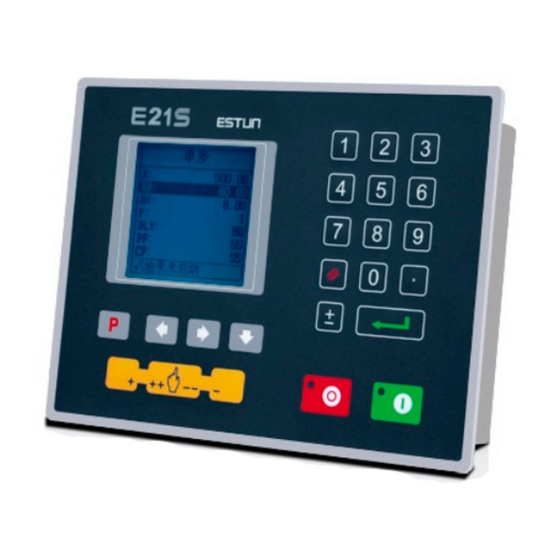
E21S Operation Manual Chapter 1 Product Overview 1.1 Product introduction This product is equipped with the shear machine dedicated numerical control device which is applicable to various users. Based on ensuring work precision, the cost of numerical control shearing machine is reduced significantly.
-
Page 5
E21S Operation Manual Functions of panel keys are described in Table 1-1. Table 1-1 Description of key functions Function description Delete key: delete all data in input area on left bottom of displayer. Enter key: confirm the input content. If no content is input, the key… -
Page 6: Displayer
E21S Operation Manual 1.3 Displayer E21S numerical control device adopts 160*160 dot matrix LCD displayer. The display area is shown in Figure 1-2. Single Title bar 200.00 50.00 9.98 20.00 Parameter display area CUT: 3.00 DLY: 1.00 Range: 0~9999.999mm Status bar Figure 1-2 Display area …
-
Page 7: Chapter 2 Operation Instruction
E21S Operation Manual Chapter 2 Operation Instruction 2.1 Basic operation procedure Basic switch over and operation procedure of the device is shown in Figure 2-1. START Press Press Manual Single-Step Press Press Press Mutil-Step PROGRAMS Press Press Press Password: 14789…
-
Page 8: Programming
E21S Operation Manual 2.2 Programming The device has two programming methods, which are single-step programming and multi-step programming. User can set up programming according to actual demand. 2.2.1 Single-step programming Single-step programming is generally used for processing single step to finish work piece processing.
-
Page 9
E21S Operation Manual Parameter name Unit Range Remarks 0~9.99 In case of single step, delay time for X axle concession. 0~9.99 There is a delay time for the cutter goes to the next work-step, after it leaves the top dead center. -
Page 10: Multi-Step Programming
E21S Operation Manual Operation steps Operation Step 4 Click , select “DX” parameter, “DLY” parameter, “PP” parameter respectively. Step 5 Set up parameter to 50mm, 2s, 10 by numerical key. Step 6 Click , system execute according to this program.
-
Page 11
E21S Operation Manual Step 5 Click , select multi-step programming parameter which requires set up, input setting up value, click , and the configuration takes effect. Step 6 In completion of set up, click , enter step parameter set page, as shown in Figure 2-6. -
Page 12
E21S Operation Manual Parameter name Unit Range Remarks CtDly 0~9.99 There is a delay time for the cutter goes to the next work-step, after it leaves the top dead center. [Note] Only the parameter CutDelay En. is set to 1, displaying this parameter. -
Page 13: Parameter Setting
E21S Operation Manual Table 2-4 Operation steps of multi-step programming example Operation step Operation Step 1 On single step parameter setting page, press to enter program selection page. Step 2 Input “2”, click , enter multi-step general parameter setting page of program 2.
-
Page 14
E21S Operation Manual Step 1 On program management page, click to enter programming constant page, as shown in Figure 2-8. On this page, programming constant can be set. CONST mm/inch: 中文/English: Pulse Time: 0.020 Version: V1.10 0:mm 1:inch Figure 2-8 Programming constant page Range of programming constant setup is shown in Table 2-5. -
Page 15
E21S Operation Manual SYS PARA 1/ 2PG X-digits: X-safe: 1.000 Step delay: 3.33 CutDelay En.: MaxCut Delay: 9.99 X-tea.in: G-tea.in: Range:0~3 Figure 2-9 System parameter setting page Step 3 Step up parameter, parameter setup range is shown in Table 2-6. -
Page 16: Manual Movement
E21S Operation Manual 2.4 Manual movement In single-step mode, axle movement can be controlled by pressing key manually. This method helps user to adjust machine tool and work piece. , Step 1 On single step parameter setup page, click to enter manual page, as shown in Figure 2-10.
-
Page 17: Chapter 3 Alarm
E21S Operation Manual Chapter 3 Alarm The device can detect internal or external abnormity automatically and send out alarm prompt. Alarm message is available on alarm list. Step 1 On programming management page, click to enter programming constant page. Step 2 On programming constant page, click to enter “Alarm history”…
-
Page 18
E21S Operation Manual Alarm number Alarm name Alarm description When count reaches preset value, A.11 Finished work system shut down automatically. In single step and multistep mode, slider A.12 Out of UDP is not on upper dead center. A.22 Encoder abnor. -
Page 19: Appendix Common Fault And Troubleshooting
E21S Operation Manual Appendix Common fault and troubleshooting Fault phenomena Trouble shooting When power on, the device will not The electrode of power supply terminal is display. connected error; please see the information of power nameplate. Voltage is too low.
Главное содержание
Контроллеры станков с ЧПУ
- Контроллер ESTUN E21 v. 1.06 (русский) — Руководство по эксплуатации (инструкция) контроллера для гидравлических листогибов.

- Контроллер ESTUN E21S v. 1.06 (русский) — Руководство по эксплуатации (инструкция) контроллера для гидравлических листорезных станков.

- Контроллер ESTUN E210 v. 1.02 (русский) — Руководство по эксплуатации (инструкция) контроллера для гидравлических листогибов.

- Контроллер DELEM DA-52s V0812 для ПО Вер.3.2 (русский) — Руководство по эксплуатации (инструкция) контроллера для гидравлических листогибов.

- JQ LASER BCS100 (русский) V.2.25 — Руководство пользователя контроллера высоты для станков лазерной резки металла с ЧПУ

- Контроллер PA 8000 Ред.04.09 Вер.ПО 3.Х (русский) — Руководство по эксплуатации (инструкция) контроллера.

Контроллер распределенного мониторинга температуры OTS3/LHD3
-
Контроллеры серии OTS3/LHD3 — инструкции по безопасности
-
Контроллеры серии OTS3/LHD3 — руководство по установке
-
Контроллеры серии OTS3/LHD3 — руководство по эксплуатации
E21S Operation Manual
Functions of panel keys are described in Table 1-1.
Table 1-1 Description of key functions
Key
Function description
Delete key: delete all data in input area on left bottom of
displayer.
Enter key: confirm the input content. If no content is input, the key
has the similar function to direction key
.
Start key: automatic start-up, top left corner of the key is operation
indicator LED. When operation is started, this indicator LED is on.
Stop key: stop operation, top left corner of the key is Stop
indicator LED. When initialize normal start-up and no operation,
this indicator LED is on.
Left direction key: page forward, cursor remove
Right direction key: page backward, cursor remove
Down direction key: select parameter downward
Function switch: switch over different function pages
Symbolic key: user input symbol, or start diagnosis.
Numeric key: when setting parameter, input value.
~
Decimal point key: when set up parameter, input decimal point.
Manual movement key: in case of manual adjustment, make
adjustment object move in forward direction at low speed.
Manual movement key: in case of manual adjustment, make
adjustment object move in backward direction at low speed.
High speed selection key: in case of manual adjustment, press
this key and press
simultaneously, make adjustment object
move in increasing direction at high speed, then press
,
make adjustment object move in decreasing direction at high
speed.
3
Хитрые задачки МКЭ и МДТТ. Вопросы/обсуждения..
Автор:
Jesse · Опубликовано: 4 часа назад
ну имхо интерес тут есть.)
например, сравниться с экспериментом и убедиться, что получим нагрузку ~1200Н до наступления потери устойчивости и потери прочности. Ну а дальше мб кто и механику разрушения применит и покажет, что при этой нагрузке рост трещины идёт и наступает хрупкое разрушение..))
Характеристики скорлупы надыбать — да, тут проблема..))
-
Page 1
E21 Installation Manual (Version: V1.09) -
Page 2: Table Of Contents
E21 Installation Manual Contents Preface ………………….1 Chapter 1 Specification ………………… 3 1.1 Display ………………….3 1.2 Internal memory ………………..3 1.3 Electrical specification ………………3 Chapter 2 Installation ………………..5 2.1 Announcements before installation …………..5 2.2 Installation space and direction …………… 5 2.3 Installation environment ………………
-
Page 3
7.2.2 Equipment grounding design …………….33 7.3 Protective measures ………………34 7.3.1 Measures to ensure electromagnetic compatibility ……….34 7.3.2 Instructions to E21 electromagnetic capability installation ……..36 7.3.3 Install freewheeling diode on relay …………..36 7.4 Demonstration of AC Asynchronies motor wiring ………. 37… -
Page 4: Preface
E21 Installation Manual Preface Target reader This manual guides the following operators to install, configure and maintain the E21 press break numerical control device: Machine tool operators Installation and maintenance personnel Range of application Installation and maintenance personnel can install and operate this device properly by referring to this manual.
-
Page 5
E21 Installation Manual Low temperature; refer to JB-T 8832-2001 General requirements for numerical control device of machine tools, 0 ℃, 2hours. Low temperature store -20℃. Criteria: normal start up, normal operation. High temperature, refer to JB-T 8832-2001 General requirements for numerical control device of machine tools, 40 ℃, 2hours. -
Page 6: Chapter 1 Specification
E21 Installation Manual Chapter 1 Specification 1.1 Display LCD display Dimension of display window: 54.38mm*54.38mm Dot matrix: 160*160 Status light Green indicates running Red indicates stop 1.2 Internal memory Capable of storing 40 programs, each program includes 25 steps at most.
-
Page 7
E21 Installation Manual Storage temperature: -20~55℃ Encoder specification Power supply: DC 12V Incremental encoder: single-ended output, with Z/C phase Output: voltage-type… -
Page 8: Chapter 2 Installation
Therefore, before turning on the power supply, check the connection of input output grounding and power supply wire. Grounding terminal of E21 digital control device must be grounded in correct way, with low impedance lower than 0.3Ω. Do not dismantle the device without authorization so as to avoid malfunction.
-
Page 9: Installation Dimension
E21 Installation Manual 2.4 Installation dimension The installation method is panel mounting. Installation dimension and drawings are shown in Figure 2-1. Unit: mm 4-M4 pressure riveting screws High 8 mm Figure 2-1 Panel Installation Dimension…
-
Page 10: Installation Layout
E21 Installation Manual 2.5 Installation layout 2.5.1 Layout of rear panel Rear panel block diagram is as shown in Figure 2-2, consisting of power port (POWER), input port (INPUT), output port (OUTPUT), encoder port (X, Y), and communication port (COMM).
-
Page 11
E21 Installation Manual Socket number External port name External port description 7 pin. 24VDC, maximum load 10mA, INPUT opto-coupler isolation, maximum withstanding voltage 40V. Incremental encoder is 12V single-ended output, with pulse frequency up to 100KHz. Meanwhile, the port supplies power externally X-ENCODER (as input power of encoder). -
Page 12: Overall Wiring Scheme
E21 Installation Manual 2.5.3 Overall wiring scheme Overall wiring scheme is as shown in Figure 2-3. Figure 2-3 Overall wiring schemes…
-
Page 13: Electrical Wiring Scheme
E21 Installation Manual 2.5.4 Electrical wiring scheme Electrical wiring scheme is as shown in Figure 2-4. 12V single-point 12V single-point incremental encoder incremental encoder Shell Encoder cable Encoder cable grounding shield layer shield layer Y-ENCODER X-ENCODER Shell grounding terminal … ……
-
Page 14: Definition Of Device Interface
E21 Installation Manual 2.6 Definition of device interface 2.6.1 Definition of power interface Definition of terminal is as shown in Table 2-2. Table 2-2 Description of power terminal Terminal No. Signal Description Input terminal of device power, connect to DC +24V.
-
Page 15: Definition Of External Output Interface
E21 Installation Manual Terminal No. Signal Description Y-axis reference point signal, DC +24V signal input, connect Y-EOT to low limit signal of Y-axis block generally. Block touches reference point switch, +24V signal is connected. Count Retain Retain The pump signal must be connected to DC 24V when the MRDY machine is normally running.
-
Page 16: Definition Of Encoder Interface
E21 Installation Manual Terminal No. Signal Description COM2 Common port of system output signal must connect to 0V of I/O power supply. 2.6.4 Definition of encoder interface Encoder interface is DB-9 plug (female), definition of terminal is as shown in Table 2-5.
-
Page 17: Chapter 3 Parameter Description Of Machine Tool
E21 Installation Manual Chapter 3 Parameter Description of Machine Tool 3.1 Enter parameter page Steps to entering parameter page are as below. Step 1 Power on, and press two times to enter Programming Constant page, as shown in Figure 3-1. On this page, program constant can be set.
-
Page 18: Parameter Description
E21 Installation Manual <Note>: You can directly enter Teach Page by input password “1212” and press on Program Constant page. Step 4 Input password 36987 on the CONST page to enter Motor-Speed Detection page, as shown in Figure 3-4. 1.X Motor Dec.
-
Page 19
E21 Installation Manual Name Default value Range Description mm/inch 0 or 1 0: Metric 1: inch 中文/English 0 or 1 0: Chinese 1: English Release Time 0~99.99s Interval between valid yield signal and unloading output when system starts. -
Page 20
E21 Installation Manual Name Default value Range Description X-Enable 0 or 1 0:disable 1:enable Encoder Dir. 0 or 1 0:decreasing 1:increasing Teach. En. 0 or 1 0:disable, enable the orientation function. 1:enable, enable the teaching function. -
Page 21
E21 Installation Manual Name Default value Range Description Repeat Enable 1~99999999 0:disable 1:enable Repeat Time 0~99.99s Interval of back gauge reposition when repeat position Mute Dis. 0~9999.999mm Conversion distance between high speed and low speed. Motor lowers speed when enter this range. -
Page 22
In general, the fixed frequency is 50Hz. [Note] The parameter description of X-axis and Y-axis are the same. If the Vacon transducer is used, the parameter setting for communicating E21 device is as below: E21 Communication Parameter Setting of Vacon P2.1 →… -
Page 23
E21 Installation Manual The parameter description of Motor-Speed Detection is as shown in Table 3-1. Table 3-1 Parameter description of Motor-Speed Detection Name Default Range Description Whether to enable the Motor-Speed Detection function. X-Motor Det. 0 or 1 0: Disabled … -
Page 24
E21 Installation Manual Name Default Range Description X-axis motor begins accelerate from High-speed to the detection end. It will not detect X-axis T3 0~9.99s the motor speed in this setting value. This parameter applies to only the inverter. [Note] The parameter description of X-axis and Y-axis are the same. -
Page 25: Chapter 4 Diagnosis
E21 Installation Manual Chapter 4 Diagnosis When diagnosis is in progress, do not start oil pump. 4.1 Enter diagnosis page This system provides diagnosis tests for input, output, keyboard, FRAM, encoder and LCD, etc. Steps to enter diagnosis page are as follows: Step 1 Power on, the device displays the single-step programming page, Stop Indicator lights.
-
Page 26: Output Diagnosis
E21 Installation Manual 4.3 Output diagnosis When you enter the DIAGNOSE page, select 2. OUT DIAG. to enter OUT DIAG. page, as shown in Figure 4-3. [Operation Guide] Using the Arrow Key to move the cursor to the corresponding port…
-
Page 27: Fram Diagnosis
E21 Installation Manual 4.5 FRAM diagnosis When you enter the DIAGNOSE page, select 4. FRAM DIAG. to enter FARM DIAG. page, as shown in Figure 4-5. , the page displays “Diagnosing”. When the diagnosis is [Operation Guide] Press success, the page will display “The result is: OK”. However, if the page long displays “Diagnosing”, it indicates the memory is failure.
-
Page 28: Lcd Diagnosis
E21 Installation Manual 4.7 LCD diagnosis When you enter the DIAGNOSE page, select 6. LED DIAG. to enter LED DIAG. page, as shown in Figure 4-7. [Operation Guide] Press , the device will star to diagnose the LCD. To stop the diagnosis, press LCD DIAG.
-
Page 29: Chapter 5 Commissioning
If necessary, cut down motor power immediately to avoid accident. 5.1 Preparation before Commissioning Check E21 power line, ground wire, input/output signal wire and encoder plug for reliable and accurate connection. Check whether output voltage of 24V switch power is normal or not.
-
Page 30: Action Commissioning
E21 Installation Manual Over.Dis.: 5.00 Repeat Enable: 1 Repeat Time: 1.00 Stop Dis.: 100 Mute Dis.: 4000 Overrun En.: 0 (Bilateral orientation is enabled) Y-Axis parameter setting Y-axis parameter setting: the method is similar to the setting of X axis parameter 5.2.2 Action commissioning…
-
Page 31: Counting Commissioning
E21 Installation Manual 5.2.4 Counting commissioning Edit multistep program on programming page (setting number of work piece is over 1, single step is excluded), press “Start”, depress pedal to dry running when X, Y axis are in position (note Y axis position and pressure), observe whether counting has increased;…
-
Page 32: Chapter 6 Maintenance
E21 Installation Manual Chapter 6 Maintenance 6.1 Instructions to maintenance In order to use this system safely and properly, follow the instructions. When power is on or system operates normally, do not open cover plate or panel as it may damage the components.
-
Page 33: Periodic Inspection
E21 Installation Manual Inspection item Standard content Standard Treatment specification Connection status Check terminal Screw is not loose Fastening screw for loosening terminal screw. LED display status Check whether LED LED (green) indicate display is correct. system running, LED (red) indicate system stop.
-
Page 34
E21 Installation Manual Inspection item Standard Standard Treatment content specification Install Tension, Mobile module Module must Secure the mobility be installed screw. If securely. CPU and I/O module loses, fasten them by screws. Dust and Visual No dust or Remove and… -
Page 35: Chapter 7 Appendix
7.2.1 Ground classification in equipment cabinet Ground in equipment cabinet is divided into three categories: Signal ground: for example, signal reference in E21 controller; Shield ground: the shield layer of communication cable can prevent the system from external interference and hinder internal noise interfere other equipment. The ground shield layer connected to be called shield ground must connect to protective ground.
-
Page 36: Equipment Grounding Design
RC net. RC network of E21 is integrated inside the product with one end connect to signal ground, and the other end connect to ground (three pins of POWER terminal), as shown in Figure 7-1.
-
Page 37: Protective Measures
7.3 Protective measures 7.3.1 Measures to ensure electromagnetic compatibility E21 and its components are specially designed for industrial environment with strong electromagnetic compatibility. But when install and operate, take possible interference by the outside into account, and improve reliability and stability of the system.
-
Page 38
E21 Installation Manual Coupling mode Cause Typical cases Inductive Changing current flows Transformer; coupling through current loop. Contactor and relay pull-in or disconnect; High frequency signal cable, etc. Radio frequency Space electromagnetic field coupling makes guide line generate induced voltage current. -
Page 39: Instructions To E21 Electromagnetic Capability Installation
E21 Installation Manual 7.3.2 Instructions to E21 electromagnetic capability installation E21 may be installed outside the cabinet. If work environment is poor, keep E21 close to cabinet as much as possible; Metal housing shall connect to protective ground via earth conductor, and ground resistance shall be no higher than 0.3 ohm;…
-
Page 40: Demonstration Of Ac Asynchronies Motor Wiring
E21 Installation Manual 7.4 Demonstration of AC Asynchronies motor wiring Demonstration of AC asynchronism motor wiring is as shown in the following figure. Power COMMUNICATION ENCODER 1, 6 2, 7 RS485A RS485B Others 8, 9 Shell EARTH Shell EARTH…
-
Page 41
E21 Installation Manual…
© FL.ru, 2005 – 2023
О проекте
Правила
Безопасность
Помощь
© FL.ru, 2005 – 2023
О проекте
Правила
Безопасность
Помощь
Наши партнеры
Сведения об ООО «Ваан» внесены в реестр аккредитованных организаций, осуществляющих деятельность в области информационных технологий. ООО «Ваан» осуществляет деятельность, связанную с использованием информационных технологий, по разработке компьютерного программного обеспечения, предоставлению доступа к программе для ЭВМ и является правообладателем программы для ЭВМ «FL.ru 2.0».
E21S Operation Manual
Functions of panel keys are described in Table 1-1.
Table 1-1 Description of key functions
Key
Function description
Delete key: delete all data in input area on left bottom of
displayer.
Enter key: confirm the input content. If no content is input, the key
has the similar function to direction key
.
Start key: automatic start-up, top left corner of the key is operation
indicator LED. When operation is started, this indicator LED is on.
Stop key: stop operation, top left corner of the key is Stop
indicator LED. When initialize normal start-up and no operation,
this indicator LED is on.
Left direction key: page forward, cursor remove
Right direction key: page backward, cursor remove
Down direction key: select parameter downward
Function switch: switch over different function pages
Symbolic key: user input symbol, or start diagnosis.
Numeric key: when setting parameter, input value.
~
Decimal point key: when set up parameter, input decimal point.
Manual movement key: in case of manual adjustment, make
adjustment object move in forward direction at low speed.
Manual movement key: in case of manual adjustment, make
adjustment object move in backward direction at low speed.
High speed selection key: in case of manual adjustment, press
this key and press
simultaneously, make adjustment object
move in increasing direction at high speed, then press
,
make adjustment object move in decreasing direction at high
speed.
3