-
Contents
-
Table of Contents
-
Bookmarks
Quick Links
E21 Press Brake Numerical Control Device
Installation Manual
V1.01
ESTUN AUTOMATION CO.,LTD
Address :
No.155 Jiangjun Road, Jiangning
Development Zone Nanjing P.R.C 211106
Postal code:211106
TEL:025-52785569
FAX:025-52785966
WEB:www.estun.com
E-mail:info@estun.com
Page 1 of 38
Related Manuals for Estun E21
Summary of Contents for Estun E21
-
Page 1
E21 Press Brake Numerical Control Device Installation Manual V1.01 ESTUN AUTOMATION CO.,LTD Address : No.155 Jiangjun Road, Jiangning Development Zone Nanjing P.R.C 211106 Postal code:211106 TEL:025-52785569 FAX:025-52785966 WEB:www.estun.com E-mail:info@estun.com Page 1 of 38… -
Page 2
Document Revision Record Serial Version Revision Description Revised by Appr Remarks Date oved V1.00 2012-6-4 Yao Qing V1.01 2012-6-6 Update Yao Qing Assembly Drawings Page 2 of 38… -
Page 3: Preface
Preface Target reader This manual is applicable to operators of E21 press brake machine numerical control device, including: Machine tool operators Installation and maintenance personnel Range of application Installation and maintenance personnel can install and operate this device properly by referring to this manual.
-
Page 4
numerical control systems of machine tools, 40 , humidity 93%~95% ℃ , 2 hours. Criteria: normal operation. Vibration impact, refer to JB-T 8832-2001 General requirements for numerical control systems of machine tools. Personnel Only authorized and properly trained person is allowed to operate this equipment. -
Page 5: Table Of Contents
Content Preface …………………….. 3 1 Specification………………….7 1.1 Display ……………………… 7 1.2 Internal memory ……………………7 1.3 Electrical specification ………………….7 1.4 Encoder specification ………………….8 2 Installation ………………….. 9 2.1 Annoucements before installation ………………9 2.2 Installation space and direction ………………..9 2.3 Installation environment ………………….
-
Page 6
7.2.2 Equipment grounding design ………………33 7.3 Protective measures………………….34 7.3.1 Measures to ensure electromagnetic compatibility …………. 34 7.3.2 Instructions to E21 electricmagnetic compability installation ……..36 7.3.3 Install freewheeling diode on relay …………….36 7.4 Demonstration of AC Asynchronism motor wiring …………. 36… -
Page 7: Specification
Specification 1.1 Display LCD display Dimension of display window:54.38mm*54.38mm Dot matrix:160*160 Status light Green indicates running; Red indicates stop. 1.2 Internal memory Capable of storing 40 programs, each program includes 25 steps at most. 1.3 Electrical specification POWER Input voltage:DC24V±10% Rated current:1A INPUT Input voltage:DC24V±10%…
-
Page 8: Encoder Specification
Encoder power Output voltage:DC12V±5% Allowable maximum output current:500mA Absolute temperature: Working temperature:0~40℃ Storage temperature:-20~55℃ 1.4 Encoder specification Power supply is DC 12V; Incremental encoder,single-ended output,with Z/C phase; Voltage-type output Page 8 of 38…
-
Page 9: Installation
Therefore, before turning on the power supply, check the connection of input output grounding and power supply wire. . Grounding terminal of E21 digital control device must be grounded in correct way, with low impedance lower than 0.3Ω.
-
Page 10: Installation Dimension
2.4 Installation dimension The installation method is panel-mounting. Installation dimension and drawings are shown in Figure 2-1. Figure 2-1 Panel Installation Dimension 2.5 Installation layout 2.5.1 Layout of rear panel Rear panel block diagram is shown in Figure 2-2, consisting of power port (POWER), input port (INPUT), output port (OUTPUT), encoder port (X, Y), and communication port (COMM).
-
Page 11: Rear Panel Port Description
Figure 2-2 Rear panel layout 2.5.2 Rear panel port description Rear panel port description is shown in Table 2-1. Table 2-1 Rear panel port description Socket number External port name External port description POWER Input terminal of system power. 13 way. 24VDC, maximum drive capability 70mA, opto-coupler…
-
Page 12: Overall Wiring Scheme
Socket number External port name External port description Incremental encoder single-ended output, with pulse frequency 100KHz. Meanwhile, port supplies Y-ENCODER power externally (as input power of encoder), rated voltage 12V, rated current 150mA, ripple voltage no higher than 100mV. RS232 For updating the system software.
-
Page 13: Definition Of System Interface
Figure 2-4 Electrical wiring schemes It is recommended to use the relay which contains diode on coil, avoid high voltage damage the circuit when cutting inductive load. Shield layer of the encoder cable shall be connected to ground, which is the metal housing of the product, with low resistor.
-
Page 14
Table 2-1 Definition of external output terminal Terminal No. Signal Description Step change signal, DC +24V signal input, connect to upper dead point signal generally,beam return to upper dead point, +24V signal is START connected, system receive step change signal, system callout the next program and execute the program. -
Page 15: Definition Of External Output Interface
Terminal No. Signal Description Common port of system input COM1 signal must be connected to 0V of I/O power. 2.6.3 Definition of external output interface Terminal definition is shown in Table 2-4. Definition of external output terminal Terminal No. Signal Description X――…
-
Page 16: Definition Of Communication Interface
Table 2-1 Definition of encoder terminal Communication Incremental encoder terminal mode Pin No. 1, 6, 8, 9 2, 7 Signal definition GND of encoder cable can be connected to any pin among 1, 6, 8, 9; VCC of encoder cable can be connected to either 2 or 7; 2.6.5 Definition of communication interface The system has integrated RS232 serial interface, port adopts DB-9 plug (male).
-
Page 17: Parameter Description Of Machine Tool
Parameter Description of Machine Tool 3.1 Enter parameter page Steps to entering parameter page are as below. Step 1 On Program Management page, click to enter Programming Constant page, as shown in Figure 3-1. On this page, program constant can be set.
-
Page 18: Parameter Specification
Step 3 Select “1. System Parameter”, then click to enter system Parameter Setting page, as shown in Figure 3-3. SYS PARA 1/ 1PG X-digits: Y-digits: X-safe: 1.000 Y-safe: 1.000 Step delay: 3333 Range:0~3 Figure 3-3 System Parameter Setting page Description You can directly enter System Parameter Setting Page by input password “94343”and click on Program Constant page.
-
Page 19
Parameter name Default Parameter Parameter description value range Decompression 0~99999ms Interval between valid delay yield signal and unloading output when system starts. X axle teach 0~9999.999mm Input current axle position when teach enable. Y axle teach 0~9999.999mm Input current axle position when teach… -
Page 20
Parameter name Default Parameter Parameter description value range X over travel 0 or 1 0:disable 1:enable enable X over travel 0~9999.999mm Over travel distance, valid distance when positioning both sides X repeat enable 1~99999999 0:disable 1:enable X repeat time 0~9999ms Interval of back gauge reposition when… -
Page 21
Parameter name Default Parameter Parameter description value range Y stop distance 0~9999.999mm Advance stop range. Motor stops and carries out inertial motion when enter this range. allowable 0.05 0~99.999mm Position tolerance, tolerance in-place signal is output when reaching this range. Y over travel 0 or 1 0:disable 1:enable… -
Page 22: Debugging
Debugging 4.1 Preparation before debugging Check E21 power line, ground wire, input/output signal wire and encoder plug for reliable and accurate connection. Check whether output voltage of 24V switch power is normal or not. 4.2 Debugging procedure Check power supply and ground wire before power on the system.
-
Page 23
Conversion distance between high and low speed:4000 Bilateral positioning enable:1 Y axle parameter setting:the method is similar to the setting of X axle parameter Step 2 X axle debugging Action debugging Press “+” to observe whether X axle moves backward. If the moving direction is opposite, then adjust phase sequence of X axle motor. -
Page 24: Actual Processing
4.4 Actual processing When the above procedures are finished, roughly correct actual position of X and Y axle by teach function. Edit single step program to carry out actual processing, measure dimension of the processed work piece, then correct scale error by teach function.
-
Page 25: Diagnosis
Diagnosis 5.1 Enter diagnosis page This system provides diagnosis tests for input, output, keyboard, FRAM, encoder and LCD, etc. Caution When diagnosis is in progress, please make sure oil pump is not started. Steps to enter diagnosis page are as follows: Step 1 Power on, system stays on single-step programming page, Stop Indicator is on.
-
Page 26: Output Diagnosis
Figure 5-2 Input diagnosis page 5.3 Output diagnosis On “System diagnosis” interface, select “2. Output diagnosis” to enter diagnosis interface, as shown in Figure 5-3. OUT01-13 on interface is output corresponding to 1-13 way. Use cursor key to select output terminal, press , the selected output terminal is open and on.
-
Page 27: Fram Diagnosis
Figure 5-4 Keyboard diagnosis page 5.5 FRAM diagnosis On “System diagnosis” interface, select “4.FRAM diagnosis” to enter storage diagnosis interface, as shown in Figure 5-5. Click to enter storage diagnosis, as shown in Figure 5-6. Figure 5-5 Storage diagnosis page Figure 5-6 Storage diagnosing page Page 27 of 38…
-
Page 28: Encoder Diagnosis
5.6 Encoder diagnosis On “System diagnosis” interface, select “5.Enc. Diagnosis” to enter encoder diagnosis interface, as shown in Figure 5-7. Rotate encoder, the page will display corresponding pulse change. C pulse signal will jump between 0 and ENC. DIAG. Encoder1: Encoder1 C:…
-
Page 29: Maintenance
Maintenance 6.1 Instructions to maintenance In order to use this system safely and properly, follow the instructions. Caution When power is on or system operates normally, do not open cover plate or panel as it may damage the components. Wiring and inspection shall be done by professionals.
-
Page 30: Periodic Inspection
Table 6-1 Routine inspection Inspection item Standard Standard Treatment content specification Basic Check installed Fasten installation screw properly. screw. status loosening, and system check seal for drop. port Check IO port Correct wiring. Correct connection connection for wiring. status loosening Connection Check terminal Screw…
-
Page 31
Inspection item Standard Standard Treatment content specification Install Tension, Mobile Module must Secure mobility module installed screw. securely. I/O module looses, fasten them by screws. Dust and Visual No dust or Remove and foreign observation foreign matter clean. matter is allowed. attachmen Connecti Tightness… -
Page 32: Appendix
7.2 Grounding design 7.2.1 Ground classification in equipment cabinet Ground in equipment cabinet is divided into three categories: Signal ground: for example, signal reference in E21 controller; Shield ground: the shield layer of communication cable can prevent the system …
-
Page 33: Equipment Grounding Design
RC net. RC network of E21 is integrated inside the product with one end connect to signal ground, and the other end connect to ground (three pins of POWER terminal), as shown in Figure 7-1.
-
Page 34: Protective Measures
7.3 Protective measures 7.3.1 Measures to ensure electromagnetic compatibility E21 and its components are specially designed for industrial environment with strong electromagnetic compatibility. But when install and operate, take possible interference by the outside into account, and improve reliability and stability of the system.
-
Page 35
Table 7-1 Ways to interfere coupling Coupling mode Cause Typical cases Direct electric Two or more circuits Many equipment share one power coupling use one guide line supply; Electrostatic discharge, etc. Capacity Capacity coupling When cables are laid in parallel, coupling will generate… -
Page 36: Instructions To E21 Electricmagnetic Compability Installation
7.3.2 Instructions to E21 electricmagnetic compability installation E21 may be installed outside the cabinet. If work environment is poor, keep E21 close to cabinet as much as possible; Metal housing shall connect to protective ground via earth conductor, and ground resistance shall be no higher than 0.3 ohm;…
-
Page 37
Page 37 of 38… -
Page 38
Page 38 of 38…
Главное содержание
Контроллеры станков с ЧПУ
- Контроллер ESTUN E21 v. 1.06 (русский) — Руководство по эксплуатации (инструкция) контроллера для гидравлических листогибов.

- Контроллер ESTUN E21S v. 1.06 (русский) — Руководство по эксплуатации (инструкция) контроллера для гидравлических листорезных станков.

- Контроллер ESTUN E210 v. 1.02 (русский) — Руководство по эксплуатации (инструкция) контроллера для гидравлических листогибов.

- Контроллер DELEM DA-52s V0812 для ПО Вер.3.2 (русский) — Руководство по эксплуатации (инструкция) контроллера для гидравлических листогибов.

- JQ LASER BCS100 (русский) V.2.25 — Руководство пользователя контроллера высоты для станков лазерной резки металла с ЧПУ

- Контроллер PA 8000 Ред.04.09 Вер.ПО 3.Х (русский) — Руководство по эксплуатации (инструкция) контроллера.

Контроллер распределенного мониторинга температуры OTS3/LHD3
-
Контроллеры серии OTS3/LHD3 — инструкции по безопасности
-
Контроллеры серии OTS3/LHD3 — руководство по установке
-
Контроллеры серии OTS3/LHD3 — руководство по эксплуатации
Изменение в правилах «Опознайки»
Один объект для опознания — одна тема.
Запрещается размещать групповые фотографии или несколько разных объектов для опознания.
Для публикации сообщений создайте учётную запись или авторизуйтесь
Вы должны быть пользователем, чтобы оставить комментарий
Войти
Уже есть аккаунт? Войти в систему.
Войти

E21 Instruction Book
Document Version: V1.03
Software Version: V1.11
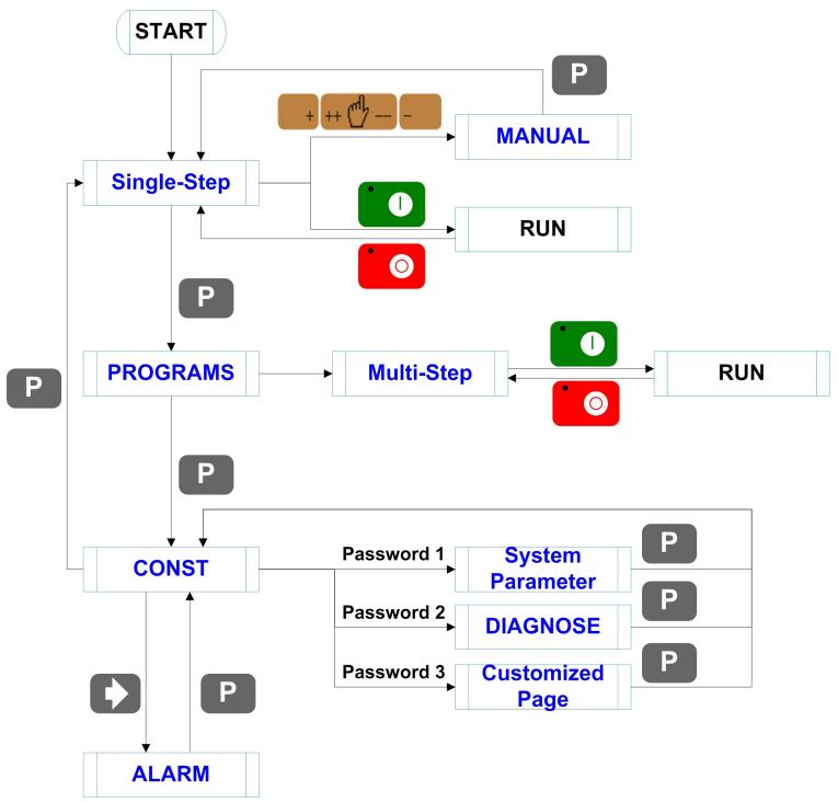
1. The default page is SINGLE; also, you can press P key several
times, switching to the SINGLE page.
2. Press Arrow Keys to select the parameter you want to program.
3. Press Numeric Keys to program a desired value.
4. Press Enter Key to complete the setting.
5. Follow the above methods to program the others parameters.
6. After finishing the program, press Startup Key to run the device.
Actual position of the back gauge
Actual position of the slider
Programmed position of the back gauge
Programmed position of the slider
Retract distance of the back gauge
Hold time of punch at the bending point
Delay time in seconds for X-axis retracting
■PP>0, indicates the residual workpieces
■PP=0, indicates the finished workpieces
<INFO> There is one batch of materials, the requirement of bending are as
following: 10 pieces, bend depth is 100.00mm, back gauge position
is 80.00mm, the retract distance is 5.00mm, the delay time for
retracting is 2 seconds, and the holding time is 3 seconds.
<PROCEDURE>
1. Program the parameter XP to 80.
2. Press Enter Key, moving the cursor to the next parameter; and
program the parameter YP to 100.00
3. Press Enter Key, moving the cursor to the next parameter, and
program the parameter DX to 5.00
4. Press Enter Key, moving the cursor to the next parameter, and
program the parameter HT to 3.00
5. Press Enter Key, moving the cursor to the next parameter, and
program the parameter DLY to 2.00
6. Press Enter Key, moving the cursor to the next parameter, and
program the parameter PP to 10
7. Press Enter Key to finish the program.
8. Press Startup Key to run the device.
<INFO> There are 50 pieces of material, which are bent as following:
The first bending: bend depth is 85.00mm, back gauge position is
50.00mm, retract distance is 5.00mm
The second bending: bend depth is 85.00mm, back gauge position
is 100.00mm, retract distance is 5.00mm
The third bending: bend depth is 85.00mm, back gauge position is
300.00mm, retract distance is 5.00mm
Put the above program into Program-No 1.
<PROCEDURE>
1. Press P key several times, switching to the PROGRAMS page
2. Select 1 and press Enter Key to enter the General Parameters
page; and program the parameter ST to 3
3. Press Enter Key, moving the cursor to the next parameter; and
program the parameter PP to 50
4. Press Enter Key, moving the cursor to the next parameter; and
program parameter DLY to 2.00
5. Press Enter Key, moving the cursor to the next parameter; and
program the parameter HT to 3.00
6. Press Enter Key and <Arrow Right> Key to enter the Step 1
Setting page; and program the parameter XP to 50.00
7. Press Enter Key, moving the cursor to the next parameter; and
program the parameter YP to 85.00
8. Press Enter Key, moving the cursor to the next parameter; and
program the parameter DX to 5.00
9. Press Enter Key, moving the cursor to the next parameter; and
program the parameter RP to 1
10. Press Enter Key and <Arrow Right> Key to enter the next step
parameters setting page; follow the above methods to program the
parameters of Step 2 and Step 3
11. After finishing the program, press P key to back the Total
Parameters page or the Step 1 page
12. Press Startup Key to run the device.
1. Press P key several times, switching to the CONST page.
2. Press <arrow right> key to enter the ALARM RECORD page.
The page can show the latest 6 alarm info. And, the following table lists
all the alarm info.
Move X-axis forwards in Manual
Movement.
Move X-axis backwards in Manual
Movement.
Move Y-axis forwards in Manual
Movement.
Move Y-axis backwards in Manual
Movement.
Re-teach the position of X-axis.
Rerun, the alarm is cleared
automatically.
Beam is not on upper
dead point
Step on the Foot Up Switch, moving
the slider to the TDC, and the alarm
will be cleared automatically.
Re-teach the position of X-axis.
Re-teach the position of Y-axis.
Check whether the pump signal is
connected, and check whether the
pump switch is on.
Check whether the encoder wiring is
normal.
Reprogram the Drive Mode for
X-axis and Y-axis.
Check whether the back gauge
motor is run normally.
Check whether the slider motor is
run normally.
Check whether the back gauge
motor is run normally.
Check whether the back gauge
motor is run normally.
Check whether the slider motor is
run normally.
Check whether the slider motor is
run normally.
Move X-axis forwards to the setting
range in Manual Movement.
Move Y-axis forwards to the setting
range in Manual Movement.
Back to factory for repairing
The screen don’t display
when power on.
■The terminal of power supply wiring is error.
Follow the nameplate to rewire.
■The source voltage is too low.
■The connector is not connected well.
The back gauge motor
doesn’t run when X-axis
is operated, but the
slider motor runs.
The wires of these two motor are in reverse,
please rewire.
The motor doesn’t run
when operating.
■Check whether the machine is impeded, or
whether the slider is back to TDC
■Check whether the motor wire is connected
well.
The motor can’t mutually
convert from high to low
■Check whether the signal is in effect, or
whether frequency converter is normal.
■Check whether parameter Mute Dis. is
programmed correctly.
The step can’t be
changed in Multi-Step
mode.
Check the START terminal is connected to
+24V when the slider is on TDC.
The counter doesn’t
work in Multi-Step mode.
Check the START terminal is connected to
+24V when the slider is on TDC.
Lose control of the
system
■Check whether the encoder cable is
connected well.
■Check whether the motor direction wiring
(X+, X-, Y+, Y-) is correct.
The actual position of
X-axis or Y-axis is
unchanged or unshown.
Check whether the encoder cable is
connected well or correctly.
When the RED indicator light is on, you can program the parameters.
Only when the page is on SINGLE, Total Parameters page or the Step 1
page, you can press Startup Key to run the device.
Press Stop Key to stop the machine, and the device backs to the previous
When the page
displays
the alarm info, you should resolve the problem
with some effective measures (see Alarm List). The device will be reset
by the self-diagnosis function.
Manual
Press key, key or key to enter the MANUAL page.
Press Arrow Keys to select the axis you want to adjust, and follow the
below table to operate.
The drive mode of the corresponding axis is motor.
■Press Time (Press Time <
Pulse Time)
■Pulse Time (Press Time >
Pulse Time)
■Press Time (Press Time <
Pulse Time)
■Pulse Time (Press Time >
Pulse Time)
<Note>: When the system is on run status, the operation of manual
movement is just valid for the X-axis.
The drive mode of the corresponding axis is frequency converter.
1. Press P key several times, switching to the PROGRAMS page.
2. Press Arrow Keys to select a desired No, or you can press
Numeric Keys to input a desired No, and then press Enter Key to
enter the General Parameters page.
4. Press Arrow Keys to select the parameter you want to program.
5. Press Numeric Keys to program a desired value.
6. Press Enter Key to complete the setting.
7. Follow the above methods to program the others general
parameters.
8. After finishing the program, press <arrow right> key to enter the
Step Setting page.
9. Follow the above methods to program the others step parameters.
10. Press <arrow right> or <arrow left> key to enter the others Step
Setting page, and program the desired parameters.
11. After finishing the program, you should back to the Total Parameters
page or the Step 1 page, and press Startup Key to run the device.
■PP>0, indicates the residual workpieces
■PP=0, indicates the finished workpieces
Delay time in seconds for X-axis retracting
Hold time of punch at the bending point
Programmed position of the back gauge in
the step
Programmed position of the slider in the step
Retract distance of the back gauge
The number of times a step is repeated
before the next step is executed
Diagnosis
<NOTE> The following is only described how to diagnose the encoder, and
for the others diagnosis, just according to the page tips to operate.
1. Press P key several times, switching to the CONST page.
2. Press Numeric Keys to input the password 5656, and press Enter
Key to enter the DIAGNOSE page.
3. Select 5. Enc. DIAG. or press Numeric Key 5 directly, and then
press Enter Key to enter the ENC. DIAG. page.
4. Rotate the encoders of X-axis and Y-axis, the page displays the
pulse changing. The corresponding C-pulse will jump between 0
and 1, which indicates the encoder port is normal.
< E21 Installation Manual >
< E21 Operation Manual >
ESTUN AUTOMATION CO., LTD
Add: 155 Jiangjun Road, Jiangning Development Zone,
Nanjing 211106, P.R.China
TEL: 025-52785866
FAX: 025-52785992
WEB: www.estun.com
- Page 1
E21 Installation Manual (Version: V1.09) -
Page 2: Table Of Contents
E21 Installation Manual Contents Preface ………………….1 Chapter 1 Specification ………………… 3 1.1 Display ………………….3 1.2 Internal memory ………………..3 1.3 Electrical specification ………………3 Chapter 2 Installation ………………..5 2.1 Announcements before installation …………..5 2.2 Installation space and direction …………… 5 2.3 Installation environment ………………
- Page 3
7.2.2 Equipment grounding design …………….33 7.3 Protective measures ………………34 7.3.1 Measures to ensure electromagnetic compatibility ……….34 7.3.2 Instructions to E21 electromagnetic capability installation ……..36 7.3.3 Install freewheeling diode on relay …………..36 7.4 Demonstration of AC Asynchronies motor wiring ………. 37… -
Page 4: Preface
E21 Installation Manual Preface Target reader This manual guides the following operators to install, configure and maintain the E21 press break numerical control device: Machine tool operators Installation and maintenance personnel Range of application Installation and maintenance personnel can install and operate this device properly by referring to this manual.
- Page 5
E21 Installation Manual Low temperature; refer to JB-T 8832-2001 General requirements for numerical control device of machine tools, 0 ℃, 2hours. Low temperature store -20℃. Criteria: normal start up, normal operation. High temperature, refer to JB-T 8832-2001 General requirements for numerical control device of machine tools, 40 ℃, 2hours. -
Page 6: Chapter 1 Specification
E21 Installation Manual Chapter 1 Specification 1.1 Display LCD display Dimension of display window: 54.38mm*54.38mm Dot matrix: 160*160 Status light Green indicates running Red indicates stop 1.2 Internal memory Capable of storing 40 programs, each program includes 25 steps at most.
- Page 7
E21 Installation Manual Storage temperature: -20~55℃ Encoder specification Power supply: DC 12V Incremental encoder: single-ended output, with Z/C phase Output: voltage-type… -
Page 8: Chapter 2 Installation
Therefore, before turning on the power supply, check the connection of input output grounding and power supply wire. Grounding terminal of E21 digital control device must be grounded in correct way, with low impedance lower than 0.3Ω. Do not dismantle the device without authorization so as to avoid malfunction.
-
Page 9: Installation Dimension
E21 Installation Manual 2.4 Installation dimension The installation method is panel mounting. Installation dimension and drawings are shown in Figure 2-1. Unit: mm 4-M4 pressure riveting screws High 8 mm Figure 2-1 Panel Installation Dimension…
-
Page 10: Installation Layout
E21 Installation Manual 2.5 Installation layout 2.5.1 Layout of rear panel Rear panel block diagram is as shown in Figure 2-2, consisting of power port (POWER), input port (INPUT), output port (OUTPUT), encoder port (X, Y), and communication port (COMM).
- Page 11
E21 Installation Manual Socket number External port name External port description 7 pin. 24VDC, maximum load 10mA, INPUT opto-coupler isolation, maximum withstanding voltage 40V. Incremental encoder is 12V single-ended output, with pulse frequency up to 100KHz. Meanwhile, the port supplies power externally X-ENCODER (as input power of encoder). -
Page 12: Overall Wiring Scheme
E21 Installation Manual 2.5.3 Overall wiring scheme Overall wiring scheme is as shown in Figure 2-3. Figure 2-3 Overall wiring schemes…
-
Page 13: Electrical Wiring Scheme
E21 Installation Manual 2.5.4 Electrical wiring scheme Electrical wiring scheme is as shown in Figure 2-4. 12V single-point 12V single-point incremental encoder incremental encoder Shell Encoder cable Encoder cable grounding shield layer shield layer Y-ENCODER X-ENCODER Shell grounding terminal … ……
-
Page 14: Definition Of Device Interface
E21 Installation Manual 2.6 Definition of device interface 2.6.1 Definition of power interface Definition of terminal is as shown in Table 2-2. Table 2-2 Description of power terminal Terminal No. Signal Description Input terminal of device power, connect to DC +24V.
-
Page 15: Definition Of External Output Interface
E21 Installation Manual Terminal No. Signal Description Y-axis reference point signal, DC +24V signal input, connect Y-EOT to low limit signal of Y-axis block generally. Block touches reference point switch, +24V signal is connected. Count Retain Retain The pump signal must be connected to DC 24V when the MRDY machine is normally running.
-
Page 16: Definition Of Encoder Interface
E21 Installation Manual Terminal No. Signal Description COM2 Common port of system output signal must connect to 0V of I/O power supply. 2.6.4 Definition of encoder interface Encoder interface is DB-9 plug (female), definition of terminal is as shown in Table 2-5.
-
Page 17: Chapter 3 Parameter Description Of Machine Tool
E21 Installation Manual Chapter 3 Parameter Description of Machine Tool 3.1 Enter parameter page Steps to entering parameter page are as below. Step 1 Power on, and press two times to enter Programming Constant page, as shown in Figure 3-1. On this page, program constant can be set.
-
Page 18: Parameter Description
E21 Installation Manual <Note>: You can directly enter Teach Page by input password “1212” and press on Program Constant page. Step 4 Input password 36987 on the CONST page to enter Motor-Speed Detection page, as shown in Figure 3-4. 1.X Motor Dec.
- Page 19
E21 Installation Manual Name Default value Range Description mm/inch 0 or 1 0: Metric 1: inch 中文/English 0 or 1 0: Chinese 1: English Release Time 0~99.99s Interval between valid yield signal and unloading output when system starts. - Page 20
E21 Installation Manual Name Default value Range Description X-Enable 0 or 1 0:disable 1:enable Encoder Dir. 0 or 1 0:decreasing 1:increasing Teach. En. 0 or 1 0:disable, enable the orientation function. 1:enable, enable the teaching function. - Page 21
E21 Installation Manual Name Default value Range Description Repeat Enable 1~99999999 0:disable 1:enable Repeat Time 0~99.99s Interval of back gauge reposition when repeat position Mute Dis. 0~9999.999mm Conversion distance between high speed and low speed. Motor lowers speed when enter this range. - Page 22
In general, the fixed frequency is 50Hz. [Note] The parameter description of X-axis and Y-axis are the same. If the Vacon transducer is used, the parameter setting for communicating E21 device is as below: E21 Communication Parameter Setting of Vacon P2.1 →… - Page 23
E21 Installation Manual The parameter description of Motor-Speed Detection is as shown in Table 3-1. Table 3-1 Parameter description of Motor-Speed Detection Name Default Range Description Whether to enable the Motor-Speed Detection function. X-Motor Det. 0 or 1 0: Disabled … - Page 24
E21 Installation Manual Name Default Range Description X-axis motor begins accelerate from High-speed to the detection end. It will not detect X-axis T3 0~9.99s the motor speed in this setting value. This parameter applies to only the inverter. [Note] The parameter description of X-axis and Y-axis are the same. -
Page 25: Chapter 4 Diagnosis
E21 Installation Manual Chapter 4 Diagnosis When diagnosis is in progress, do not start oil pump. 4.1 Enter diagnosis page This system provides diagnosis tests for input, output, keyboard, FRAM, encoder and LCD, etc. Steps to enter diagnosis page are as follows: Step 1 Power on, the device displays the single-step programming page, Stop Indicator lights.
-
Page 26: Output Diagnosis
E21 Installation Manual 4.3 Output diagnosis When you enter the DIAGNOSE page, select 2. OUT DIAG. to enter OUT DIAG. page, as shown in Figure 4-3. [Operation Guide] Using the Arrow Key to move the cursor to the corresponding port…
-
Page 27: Fram Diagnosis
E21 Installation Manual 4.5 FRAM diagnosis When you enter the DIAGNOSE page, select 4. FRAM DIAG. to enter FARM DIAG. page, as shown in Figure 4-5. , the page displays “Diagnosing”. When the diagnosis is [Operation Guide] Press success, the page will display “The result is: OK”. However, if the page long displays “Diagnosing”, it indicates the memory is failure.
-
Page 28: Lcd Diagnosis
E21 Installation Manual 4.7 LCD diagnosis When you enter the DIAGNOSE page, select 6. LED DIAG. to enter LED DIAG. page, as shown in Figure 4-7. [Operation Guide] Press , the device will star to diagnose the LCD. To stop the diagnosis, press LCD DIAG.
-
Page 29: Chapter 5 Commissioning
If necessary, cut down motor power immediately to avoid accident. 5.1 Preparation before Commissioning Check E21 power line, ground wire, input/output signal wire and encoder plug for reliable and accurate connection. Check whether output voltage of 24V switch power is normal or not.
-
Page 30: Action Commissioning
E21 Installation Manual Over.Dis.: 5.00 Repeat Enable: 1 Repeat Time: 1.00 Stop Dis.: 100 Mute Dis.: 4000 Overrun En.: 0 (Bilateral orientation is enabled) Y-Axis parameter setting Y-axis parameter setting: the method is similar to the setting of X axis parameter 5.2.2 Action commissioning…
-
Page 31: Counting Commissioning
E21 Installation Manual 5.2.4 Counting commissioning Edit multistep program on programming page (setting number of work piece is over 1, single step is excluded), press “Start”, depress pedal to dry running when X, Y axis are in position (note Y axis position and pressure), observe whether counting has increased;…
-
Page 32: Chapter 6 Maintenance
E21 Installation Manual Chapter 6 Maintenance 6.1 Instructions to maintenance In order to use this system safely and properly, follow the instructions. When power is on or system operates normally, do not open cover plate or panel as it may damage the components.
-
Page 33: Periodic Inspection
E21 Installation Manual Inspection item Standard content Standard Treatment specification Connection status Check terminal Screw is not loose Fastening screw for loosening terminal screw. LED display status Check whether LED LED (green) indicate display is correct. system running, LED (red) indicate system stop.
- Page 34
E21 Installation Manual Inspection item Standard Standard Treatment content specification Install Tension, Mobile module Module must Secure the mobility be installed screw. If securely. CPU and I/O module loses, fasten them by screws. Dust and Visual No dust or Remove and… -
Page 35: Chapter 7 Appendix
7.2.1 Ground classification in equipment cabinet Ground in equipment cabinet is divided into three categories: Signal ground: for example, signal reference in E21 controller; Shield ground: the shield layer of communication cable can prevent the system from external interference and hinder internal noise interfere other equipment. The ground shield layer connected to be called shield ground must connect to protective ground.
-
Page 36: Equipment Grounding Design
RC net. RC network of E21 is integrated inside the product with one end connect to signal ground, and the other end connect to ground (three pins of POWER terminal), as shown in Figure 7-1.
-
Page 37: Protective Measures
7.3 Protective measures 7.3.1 Measures to ensure electromagnetic compatibility E21 and its components are specially designed for industrial environment with strong electromagnetic compatibility. But when install and operate, take possible interference by the outside into account, and improve reliability and stability of the system.
- Page 38
E21 Installation Manual Coupling mode Cause Typical cases Inductive Changing current flows Transformer; coupling through current loop. Contactor and relay pull-in or disconnect; High frequency signal cable, etc. Radio frequency Space electromagnetic field coupling makes guide line generate induced voltage current. -
Page 39: Instructions To E21 Electromagnetic Capability Installation
E21 Installation Manual 7.3.2 Instructions to E21 electromagnetic capability installation E21 may be installed outside the cabinet. If work environment is poor, keep E21 close to cabinet as much as possible; Metal housing shall connect to protective ground via earth conductor, and ground resistance shall be no higher than 0.3 ohm;…
-
Page 40: Demonstration Of Ac Asynchronies Motor Wiring
E21 Installation Manual 7.4 Demonstration of AC Asynchronies motor wiring Demonstration of AC asynchronism motor wiring is as shown in the following figure. Power COMMUNICATION ENCODER 1, 6 2, 7 RS485A RS485B Others 8, 9 Shell EARTH Shell EARTH…
- Page 41
E21 Installation Manual…
Главное содержание
Контроллеры станков с ЧПУ
- Контроллер ESTUN E21 v. 1.06 (русский) — Руководство по эксплуатации (инструкция) контроллера для гидравлических листогибов.
- Контроллер ESTUN E21S v. 1.06 (русский) — Руководство по эксплуатации (инструкция) контроллера для гидравлических листорезных станков.
- Контроллер ESTUN E210 v. 1.02 (русский) — Руководство по эксплуатации (инструкция) контроллера для гидравлических листогибов.
- Контроллер DELEM DA-52s V0812 для ПО Вер.3.2 (русский) — Руководство по эксплуатации (инструкция) контроллера для гидравлических листогибов.
- JQ LASER BCS100 (русский) V.2.25 — Руководство пользователя контроллера высоты для станков лазерной резки металла с ЧПУ
- Контроллер PA 8000 Ред.04.09 Вер.ПО 3.Х (русский) — Руководство по эксплуатации (инструкция) контроллера.
Контроллер распределенного мониторинга температуры OTS3/LHD3
-
Контроллеры серии OTS3/LHD3 — инструкции по безопасности
-
Контроллеры серии OTS3/LHD3 — руководство по установке
-
Контроллеры серии OTS3/LHD3 — руководство по эксплуатации
Estun E21 Controller Manual
Preface
This manual describes operation of E21 numerical control device and is meant for operators who are instructed for operation of the device. Operator shall read through this manual and know operation requirements before using this device.
Copy right is preserved by ESTUN. It is not allowed to add or delete part or all of the manual content without ESTUN’s consent. Do not use part or all of manual content for the third party’s design.
E21 device provides complete software control and has no mechanical protection device for operator or the tool machine. Therefore, in case of malfunction, machine tool must provide protection device for operator and external part of the machine tool. ESTUN is not responsible for any direct or indirect losses caused by normal or abnormal operation of the device.
ESTUN preserves the right to modifying this manual in the event of function adding or print error.
1.1 Product introduction
This product is equipped with press brake machine dedicated numerical control device which is applicable to various users. On the basis of ensuring work precision, the cost of numerical control bending machine is reduced significantly.
Features of this product are listed below:
Positioning control of back gauge.
Intelligent positioning control.
Unilateral and bidirectional positioning which eliminates spindle clearance effectively.
Retract functions.
Automatic reference searching.
One-key parameter backup and restore.
Fast position indexing.
40 programs storage space, each program has 25 steps.
Power-off protection.
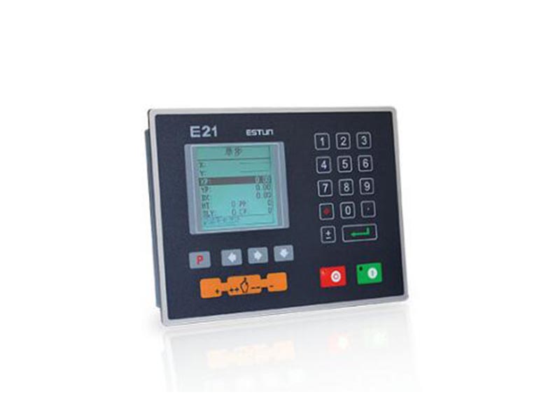
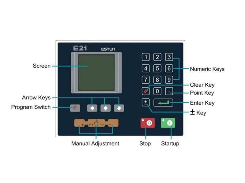
1.2 Operation panel
Operation panel is shown in Figure 1-1.
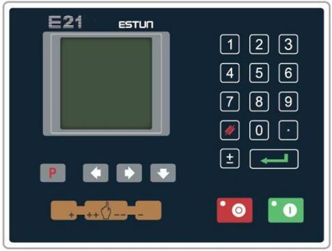
Figure 1-1 Operation panel
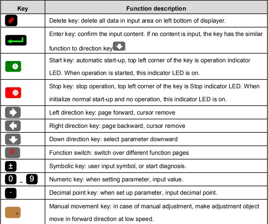
Functions of panel keys are described in Table 1-1.
Table 1-1 Description of key functions
| Key | Function description |
| Delete key: delete all data in input area on left bottom of displayer. | |
| Enter key: confirm the input content. If no content is input, the key has the similar function to direction key |
|
| Start key: automatic start-up, top left corner of the key is operation indicator LED. When operation is started, this indicator LED is on. | |
| Stop key: stop operation, top left corner of the key is Stop indicator LED. When initialize normal start-up and no operation, this indicator LED is on. | |
| Left direction key: page forward, cursor remove | |
| Right direction key: page backward, cursor remove | |
| Down direction key: select parameter downward | |
| Function switch: switch over different function pages | |
| Symbolic key: user input symbol, or start diagnosis | |
| Numeric key: when setting parameter, input value | |
| Decimal point key: when set up parameter, input decimal point. | |
| Manual movement key: in case of manual adjustment, make adjustment object move in forward direction at low speed. | |
| Manual movement key: in case of manual adjustment, make adjustment object move in backward direction at low speed | |
| High speed selection key: in case of manual adjustment, press this key and press |
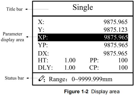
1.3 Displayer
E21 numerical control device adopts 160*160 dot matrix LCD displayer. The display area is shown in Figure 1-2.
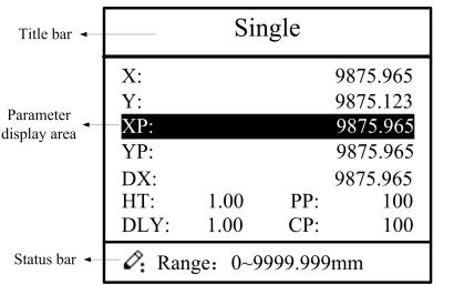
Figure 1-2 Display area
Title bar: display relevant information of current page, such as its name, etc.
Parameter display area: display parameter name, parameter value and system information.
Status bar: display area of input information and prompt message, etc.
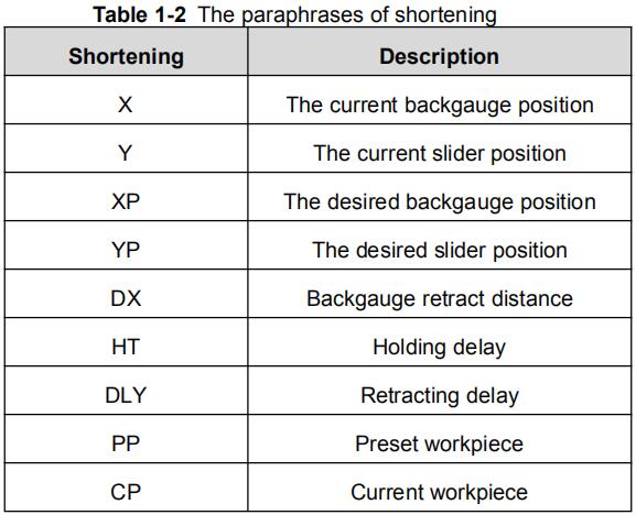
The paraphrases of shortening on this page are as shown in Table 1-2.
Table 1-2 The paraphrases of shortening
| Shortening | Description |
| X | The current backgauge position |
| Y | The current slider position |
| XP | The desired backgauge position |
| YP | The desired slider position |
| DX | Backgauge retract distance |
| HT | Holding delay |
| DLY | Retracting delay |
| PP | Preset workpiece |
| CP | Current workpiece |
Part2 — Operation Instruction
2.1 Basic operation procedure
Basic switch over and operation procedure of the device is shown in Figure 2-1.
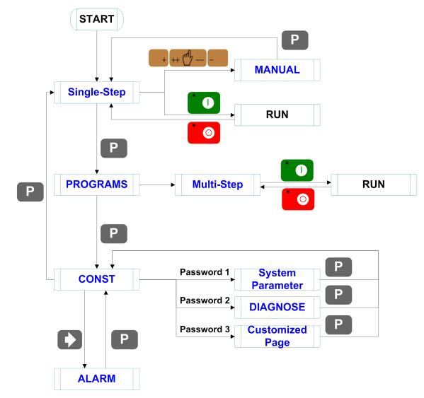
Figure 2-1 Basic Operational Flow
2.2 Programming
The device has two programming methods, which are single-step programming and multi-step programming. User can set up programming according to actual demand.
2.2.1 Single-step programming
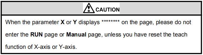
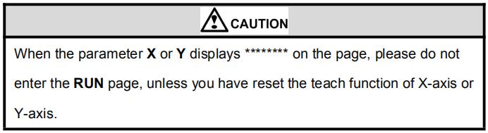
Caution: When the parameter X or Y displays ******** on the page, please do not enter the RUN page or Manual page, unless you have reset the teach function of X-axis or Y-axis.
Single-step programming is generally used for processing single step to finish work piece processing. When controller is power on, it will automatically enter single-step program page.
Operation steps
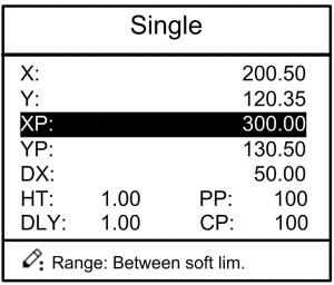
Step 1 After starting up, the device will enter setting up page of single-step program automatically, as shown in Figure 2-2.
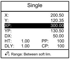
Figure 2-2 Single-step program setting page
Step 2 Press![]() , select parameter which needs to be set up, press
, select parameter which needs to be set up, press ![]() numerical key to input program value, press to complete input.
numerical key to input program value, press to complete input.
[Note] Parameter can only be set when Stop indicator is on.
Setting range of singe step parameter is shown in Table 2-1.
| Parameter name | Unit | Set up range | Remarks |
| X | mm/inch | / | Current position of X axis, unable to be modified. |
| Y | mm/inch | / | Current position of Y axis, unable to be modified. |
| XP | mm/inch | 0~9999.999 | Program position of X axis. |
| YP | mm/inch | 0~9999.999 | Target position of Y axis. |
| DX | mm/inch | 0~9999.999 | Retract distance of X axis. |
| HT | s | 0~99.99 | The time between concession signal valid and end hold time output. |
| DLY | s | 0~99.99 | In case of single step, delay time for X axis concession. |
| PP | / | 0~99.99 | Number of preset work piece |
| CP | / | 0~99.99 | Number of current work piece. |
Step 3 Press ![]() , system will execute according to this program, as shown in Figure 2-3.
, system will execute according to this program, as shown in Figure 2-3.
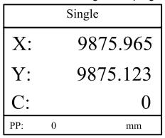
Figure 2-3 Single step operation page
- Operation example
On single-step program page, program bending depth to 100.0mm, back gauge position to
80.00mm, retract distance to 50mm, concession waiting time to 2s, holding time to 3s, work
piece to 10.
Operation steps are shown in Table 2-2.
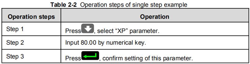
Table 2-2 Operation steps of single step example
| Operation steps | Operation |
| Step1 | Press |
| Step2 | Input 80.00 by numerical key. |
| Step3 | Press |
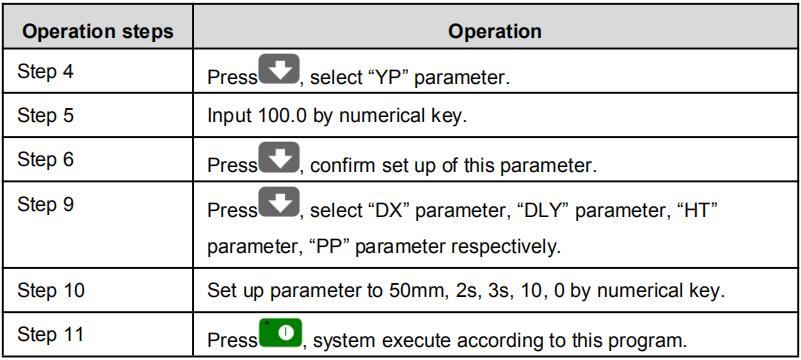
| Step4 | Press |
| Step5 | Input 100.0 by numerical key. |
| Step6 | Press |
| Step9 | Press parameter, “HT” parameter, “PP” parameter respectively. |
| Step10 | Set up parameter to 50mm, 2s, 3s, 10, 0 by numerical key. |
| Step11 | Press |
2.2.2 Multi-step programming
Caution: When the parameter X or Y displays ******** on the page, please do not enter the RUN page, unless you have reset the teach function of X-axis or Y-axis.
Multi-step program is used for processing single work piece of different processing steps, realize consecutive implementation of multi-steps, and improve processing efficiency.
Operation step
Step 1 Power on, the device displays the single-step parameter page automatically.
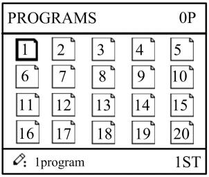
Step 2 Press ![]() , switch to program manage page, as shown in Figure 2-4.
, switch to program manage page, as shown in Figure 2-4.
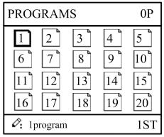
Figure 2-4 Program management page
Step 3 Press ![]()
![]()
![]() , select program serial number, or input program number directly, such as input “1”.
, select program serial number, or input program number directly, such as input “1”.
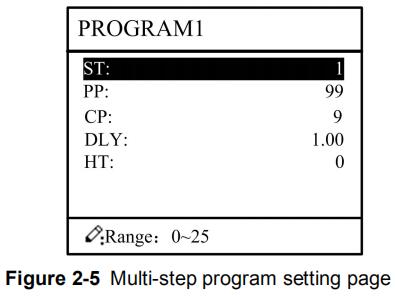
Step 4 Press ![]() , enter multi-step program setting page, as shown in Figure 2-5.
, enter multi-step program setting page, as shown in Figure 2-5.
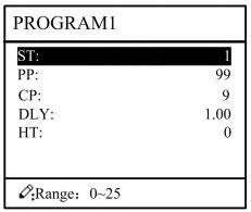
Figure 2-5 Multi-step
Step 5 Press ![]() , select multi-step programming parameter which requires set up, input
, select multi-step programming parameter which requires set up, input
setting up value, press ![]() , and the set up takes effect.
, and the set up takes effect.
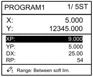
Step 6 In completion of set up, press ![]() , enter step parameter set page, as shown in Figure 2-6.
, enter step parameter set page, as shown in Figure 2-6.
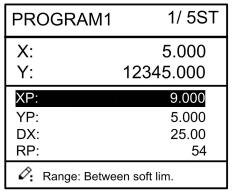
Figure 2-6 Step parameter set page
Step 7 Press ![]() , select step parameter that needs to be set up, input program value, press
, select step parameter that needs to be set up, input program value, press ![]() , and the setup takes effect.
, and the setup takes effect.
Step 8 Press ![]()
![]() to switch over between steps. If the current step is the first step, press
to switch over between steps. If the current step is the first step, press ![]() to enter the last page of step parameter setting; if the current step is the last one, press
to enter the last page of step parameter setting; if the current step is the last one, press ![]() to enter the first page of step parameter setting.
to enter the first page of step parameter setting.
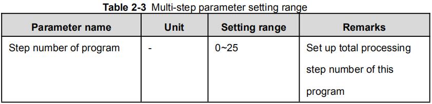
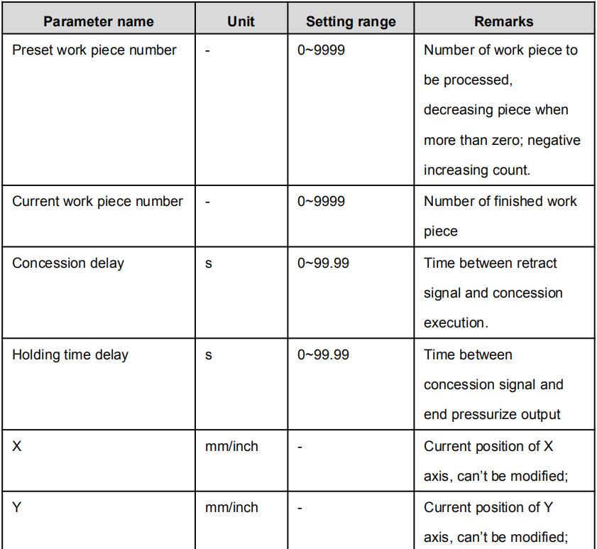
Multi-step parameter setting range is shown in Table 2-3.
Table 2-3 Multi-step parameter setting range
| Parameter name | Unit | Setting range | Remarks |
| Step number of program | / | 0~25 | Set up total processing step number of this program |
| Preset work piece number | / | 0~9999 | Number of work piece to be processed, decreasing piece when more than zero; negative increasing count. |
| Current work piece number | / | 0~9999 | Number of finished work piece |
| Concession delay | s | 0~99.99 | Time between retract signal and concession execution. |
| Holding time delay | s | 0~99.99 | Time between concession signal and end pressurize output |
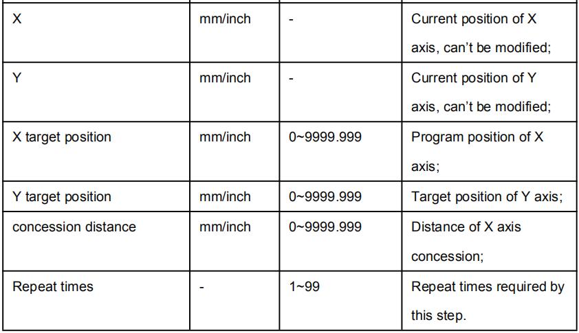
| X | mm/inch | / | Current position of X axis, can’t be modified; |
| Y | mm/inch | / | Current position of Y axis, can’t be modified; |
| X target position | mm/inch | / | Program position of X axis; |
| Y target position | mm/inch | / | Target position of Y axis; |
| concession distance | mm/inch | 0~9999.999 | Distance of X axis concession; |
| Repeat times | / | 1~99 | Repeat times required by this step. |
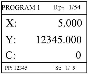
Step 9 Press ![]() , system will operate according to this program, as shown in Figure 2-7.
, system will operate according to this program, as shown in Figure 2-7.
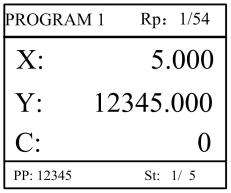
Figure 2-7 Multi-step programming operation page
- Operation example
[Background] One work piece requires processing 50 as shown below;
First bend: 50mm;
Second bend: 100mm;
Third bend: the other direction 300mm;
[Analysis] according to work piece and technological conditions of machine tool:
First bend: X axis position is 50.0mm; Y axis position is 85.00mm, concession 50mm;
The second bend: X axis position is 100.0mm; Y axis position is 85.00mm, concession 50mm;
The third bend: X axis position is 300.0mm; Y axis position is 85.00mm, concession 50mm;
Edit processing program of this work piece on No. 2 program.
Operation procedure is shown in Table 2-4.
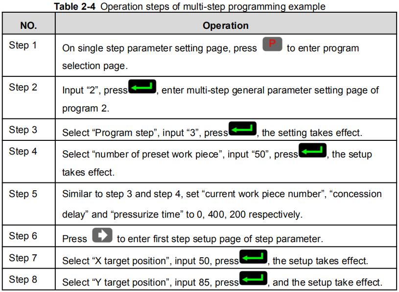
Table 2-4 Operation steps of multi-step programming example
| No. | Operation |
| Step1 | On single step parameter setting page, press |
| Step2 | Input “2”, press program 2. |
| Step3 | Select “Program step”, input “3”, press |
| Step4 | Select “number of preset work piece”, input “50”, press takes effect. |
| Step5 | Similar to step 3 and step 4, set “current work piece number”, “concession delay” and “pressurize time” to 0, 400, 200 respectively. |
| Step6 | Press |
| Step7 | Select “X target position”, input 50, press |
| Step8 | Select “Y target position”, input 85, press |
| Step9 | Similar to step 7, 8, set up “concession distance” and “repeat times” to 50, 1 respectively. |
| Step10 | Press method is similar to that of step one. |
| Step11 | Press |
<Note>
■ In completion of multi-step programming, return to start step before launching the system; otherwise, the program will start position processing at current step.
■ Press left and right direction key to circulate page turning and browsing among all step parameters.
■ Program can be called and revised again.
■In completion of processing all work pieces (50 in the example), system stops automatically. Restart directly will start another round of processing 50 work pieces.
2.3 Parameter setting
User can setup all parameters required for normal operation of the system, including system parameter, X axis parameter and Y axis parameter.
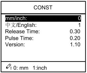
Step 1 On program management page, press ![]() to enter programming constant page, as shown in Figure 2-8. On this page, programming constant can be set.
to enter programming constant page, as shown in Figure 2-8. On this page, programming constant can be set.
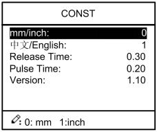
Figure 2-8 Programming constant page
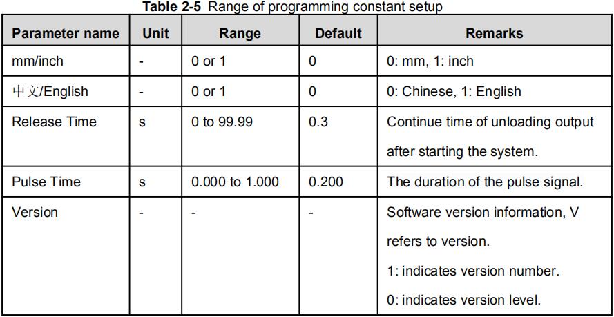
Range of programming constant setup is shown in Table 2-5.
Table 2-5 Range of programming constant setup
| Parameter name | Unit | Range | Default | Remarks |
| mm/inch | / | 0 or 1 | 0 | 0: mm, 1: inch |
| 中文/English | / | 0 or 1 | 0 | 0: Chinese, 1: English |
| Release Time | s | 0 to 99.99 | 0.3 | Continue time of unloading output after starting the system. |
| Pulse Time | s | Time s 0.000 to 1.000 | 0.2 | The duration of the pulse signal. |
| Version | / | / | / | Software version information, V refers to version. 1: indicates version number. 0: indicates version level. |
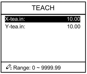
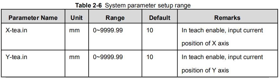
Step 2 Input password “1212”, press ![]() to enter the Teach Page, as shown in Figure 2-9.
to enter the Teach Page, as shown in Figure 2-9.
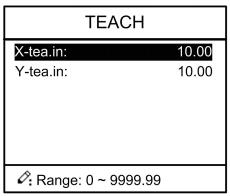
Figure 2-9 System parameter setting page
Step up parameter, parameter setup range is shown in Table 2-6.
Table 2-6 System parameter setup range
| Parameter name | Unit | Range | Default | Remarks |
| X-tea.in | mm | 0~9999.99 | 10 | In teach enable, input current position of X axis |
| Y-tea.in | mm | 0~9999.99 | 10 | In teach enable, input current position of Y axis |
<How to Teach>: You can directly measure the positions of slider and back gauge. If the measurement is difficult, you can program and operate any one process, and then measure the accomplished workpiece.
Step 3 Press ![]() , return to programming constant page.
, return to programming constant page.
—-End
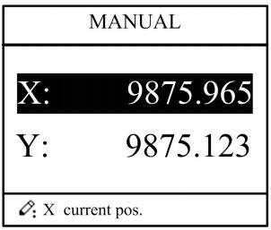
2.4 Manual adjustment
In single-step mode, axis movement can be controlled by pressing key manually. This method helps user to adjust machine tool and work piece.
Step 1 On single step parameter setup page, press ![]() or
or ![]() to enter manual page, as shown in Figure 2-10.
to enter manual page, as shown in Figure 2-10.

Figure 2-10 Manual page
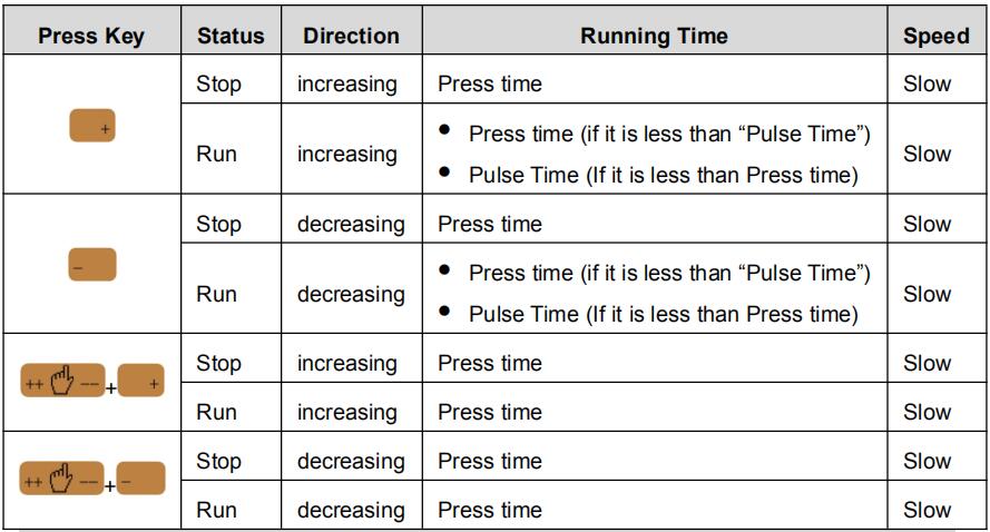
Step 2 According to your actual requirement, following the above table to adjust the position of the axis. — If the drive mode of the corresponding axis is common motor:
| Press Key | Status | Direction | Running Time | Speed |
| Stop | increasing | Press time | Slow | |
| Run | increasing | Press time (if it is less than “Pulse Time”) Pulse Time (If it is less than Press time) |
Slow | |
| Stop | decreasing | Press time | Slow | |
| Run | decreasing | Press time (if it is less than “Pulse Time”) Pulse Time (If it is less than Press time) |
Slow | |
| Stop | increasing | Press time | Slow | |
| Run | increasing | Press time | Slow | |
| Stop | decreasing | Press time | Slow | |
| Run | decreasing | Press time | Slow |
<Note>: When the system is on run status, the operation of manual adjustment is just valid for the X-axis.
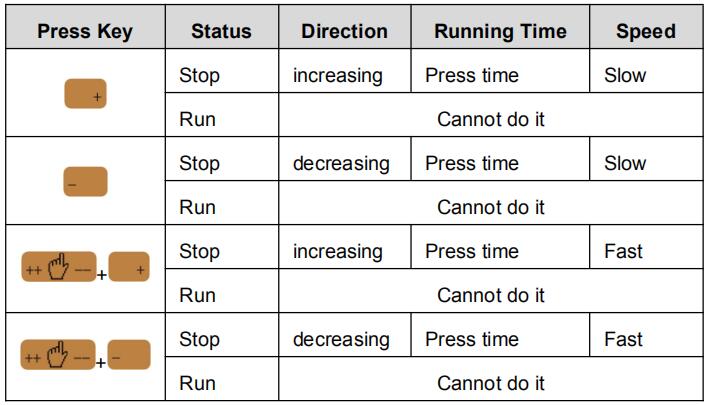
— If the drive mode of the corresponding axis is frequency:
| Press Key | Status | Direction | Running Time | Speed |
| Stop | increasing | Press time | Slow | |
| Run | / | |||
| Stop | decreasing | Press time | Slow | |
| Run | / | |||
| Stop | increasing | Press time | Fast | |
| Run | / | |||
| Stop | decreasing | Press time | Fast | |
| Run | / |
Step 3 Press ![]() return to single step parameter setting page.
return to single step parameter setting page.
—-End
Part3 — Alarm
The device can detect internal or external abnormity automatically and send out alarm prompt. Alarm message is available on alarm list.
Step 1 On programming management page, press ![]() to enter programming constant page.
to enter programming constant page.
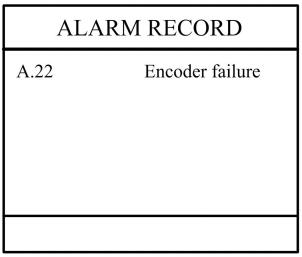
Step 2 On programming constant page, press ![]() to enter “Alarm history” page to view all alarm history.
to enter “Alarm history” page to view all alarm history.
As shown in Figure 3-1, the latest 6 alarms, alarm number and causes can be viewed on this page
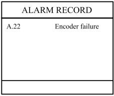
Figure 3-1 Alarm history page
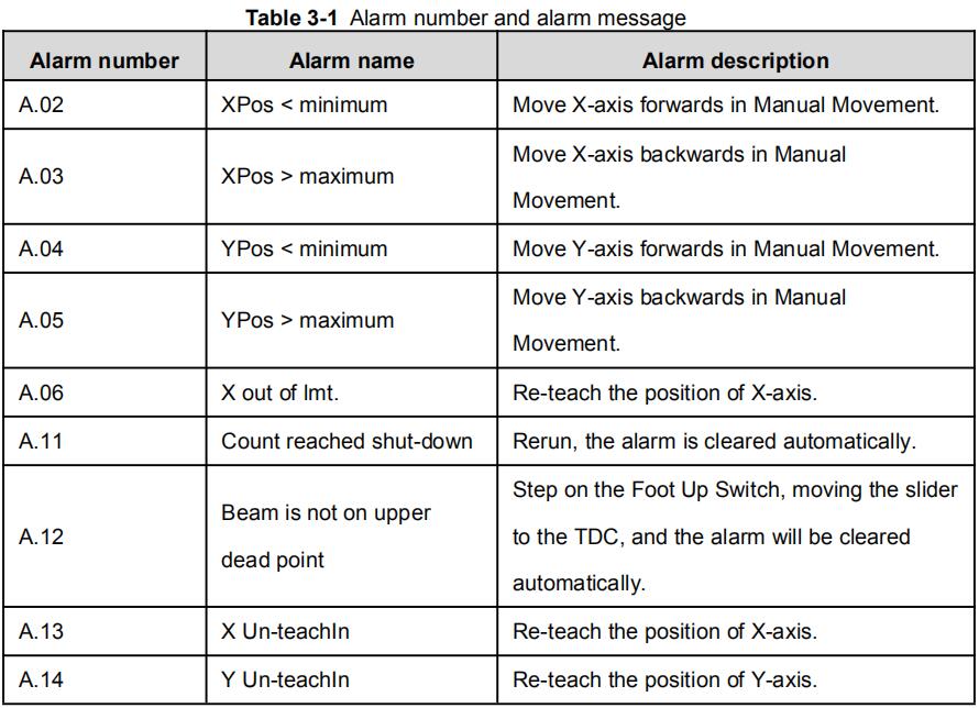
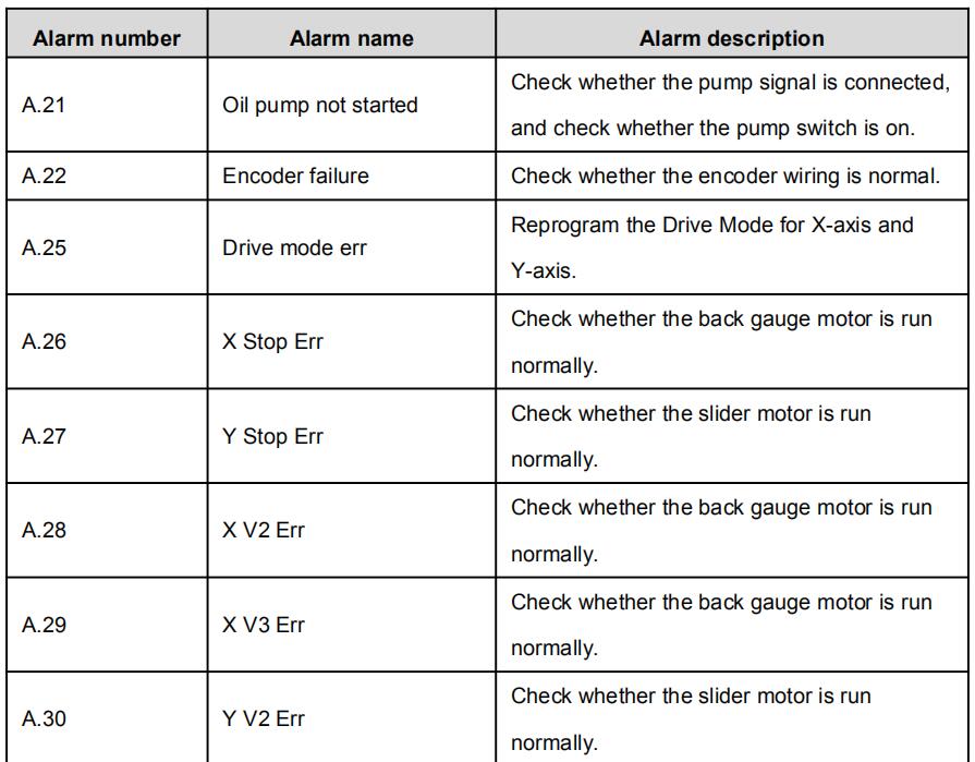
Alarm history and message is shown in Table 3-1.
Table 3-1 Alarm number and alarm message
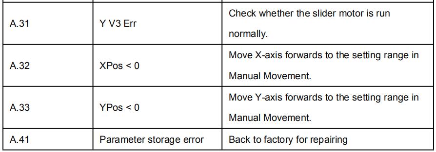
| Alarm number | Alarm name | Alarm description |
| A.02 | XPos < minimum | Move X-axis forwards in Manual Movement. |
| A.03 | XPos > maximum | Move X-axis backwards in Manual Movement. |
| A.04 | YPos < minimum | Move Y-axis forwards in Manual Movement. |
| A.05 | YPos > maximum | Move Y-axis backwards in Manual Movement. |
| A.06 | X out of lmt. | Re-teach the position of X-axis. |
| A.11 | Count reached shut-down | Rerun, the alarm is cleared automatically. |
| A.12 | Beam is not on upper dead point | Step on the Foot Up Switch, moving the slider to the TDC, and the alarm will be cleared automatically. |
| A.13 | X Un-teachIn | Re-teach the position of X-axis. |
| A.14 | Y Un-teachIn | Re-teach the position of Y-axis. |
| A.21 | Oil pump not started | Check whether the pump signal is connected, and check whether the pump switch is on. |
| A.22 | Encoder failure | Check whether the encoder wiring is normal. |
| A.25 | Drive mode err | Reprogram the Drive Mode for X-axis and Y-axis. |
| A.26 | X Stop Err | Check whether the back gauge motor is run normally |
| A.27 | Y Stop Err | Check whether the slider motor is run normally. |
| A.28 | X V2 Err | Check whether the back gauge motor is run normally. |
| A.29 | X V3 Err | Check whether the back gauge motor is run normally. |
| A.30 | Y V2 Err | Check whether the slider motor is run normally. |
| A.31 | Y V3 Err | Check whether the slider motor is run normally. |
| A.32 | XPos < 0 | Move X-axis forwards to the setting range in Manual Movement. |
| A.33 | YPos < 0 | Move Y-axis forwards to the setting range in Manual Movement. |
| A.41 | Parameter storage error | Back to factory for repairing |
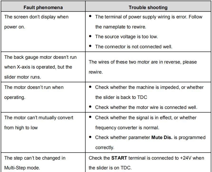
Appendix Common Fault and Troubleshooting
| Fault phenomena | Trouble shooting |
| The screen don’t display when power on. |
The terminal of power supply wiring is error. Follow the nameplate to rewire. The source voltage is too low. The connector is not connected well. |
| The back gauge motor doesn’t run when X-axis is operated, but the slider motor runs |
The wires of these two motor are in reverse, please rewire. |
| The motor doesn’t run when operating. |
Check whether the machine is impeded, or whether the slider is back to TDC Check whether the motor wire is connected well. |
| The motor can’t mutually convert from high to low |
Check whether the signal is in effect, or whether frequency converter is normal. Check whether parameter Mute Dis. is programmed correctly. |
| The step can’t be changed in Multi-Step mode. |
Check the START terminal is connected to +24V when the slider is on TDC. |
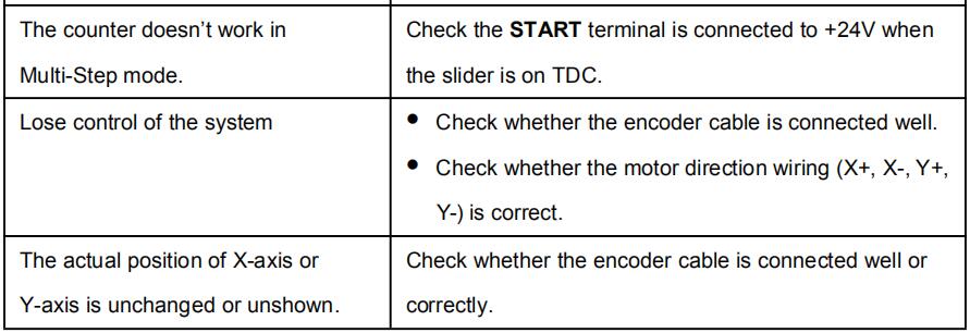
| The counter doesn’t work in Multi-Step mode. |
Check the START terminal is connected to +24V when the slider is on TDC. |
| Lose control of the system | Check whether the encoder cable is connected well. Check whether the motor direction wiring (X+, X-, Y+, Y-) is correct. |
| The actual position of X-axis or Y-axis is unchanged or unshown. | Check whether the encoder cable is connected well or correctly. |
—End
Chapter 1 Preface
This manual describes operation of Estun E21 controller and is meant for operators who are instructed for operation of the device. Operator shall read through this manual and know operation requirements before using this device.
Copy right is preserved by ESTUN. It is not allowed to add or delete part or all of the manual content without ESTUN’s consent. Do not use part or all of manual content for the third party’s design.
E21 device provides complete software control and has no mechanical protection device for operator or the tool machine. Therefore, in case of malfunction, machine tool must provide protection device for operator and external part of the machine tool. ESTUN is not responsible for any direct or indirect losses caused by normal or abnormal operation of the device.
ESTUN preserves the right to modifying this manual in the event of function adding or print error.
1.1 Product introduction
This product is equipped with press brake machine dedicated numerical control device which is applicable to various users. On the basis of ensuring work precision, the cost of numerical control bending machine is reduced significantly.
Features of this product are listed below:
- Positioning control of back gauge.
- Intelligent positioning control.
- Unilateral and bidirectional positioning which eliminates spindle clearance effectively.
- Retract functions.
- Automatic reference searching.
- One-key parameter backup and restore.
- Fast position indexing.
- 40 programs storage space, each program has 25 steps.
- Power-off protection.
1.2 Operation panel
Operation panel is shown in Figure 1-1.
Functions of panel keys are described in Table 1-1.
1.3 Displayer
E21 numerical control device adopts 160*160 dot matrix LCD displayer. The display area is shown in Figure 1-2.
- Title bar: display relevant information of current page, such as its name, etc.
- Parameter display area: display parameter name, parameter value and system information.
- Status bar: display area of input information and prompt message, etc.
The paraphrases of shortening on this page are as shown in Table 1-2.

Chapter 2 Operation Instruction
2.1 Basic operation procedure
Basic switch over and operation procedure of the device is shown in Figure 2-1
2.2 Programming
The device has two programming methods, which are single-step programming and multi-step programming. User can set up programming according to actual demand.
2.2.1 Single-step programming
Single-step programming is generally used for processing single step to finish work piece processing. When controller is power on, it will automatically enter single-step program page.
Operation steps
Step 1 After starting up, the device will enter setting up page of single-step program automatically, as shown in Figure 2-2
[Note] Parameter can only be set when Stop indicator is on.
Setting range of singe step parameter is shown in Table 2-1.
Step 2 Press “down arrow button”, select parameter which needs to be set up.
Step 3 Press below button, system will execute according to this program.
Operation example
On single-step program page, program bending depth to 100.0mm, back gauge position to 80.00mm, retract distance to 50mm, concession waiting time to 2s, holding time to 3s, work piece to 10.
Operation steps are shown in Table 2-2.
2.2.2 Multi-step programming
Multi-step program is used for processing single work piece of different processing steps,realize consecutive implementation of multi-steps, and improve processing efficiency.
Operation step
Step 1 Power on, the device displays the single-step parameter page automatically.
Step 2 Press “P”, switch to program manage page, as shown in Figure 2-4

Step 3 Press “left down or left arrow” button, select program serial number, or input program number directly, such as input “1”.
![]()
Step 4 Press”left arrow button” , enter multi-step program setting page.
![]()
Step 5 Press “down arrow” button, select multi-step programming parameter which requires set up, input setting up value.
![]()
Press “left arrow” button, and the set up takes effect.
![]()
Step 6 In completion of set up, press , enter step parameter set page, as shown in Figure2-6.
Step 7 Press “down arrow” button , select step parameter that needs to be set up, input program value, press “left arrow” button, and the setup takes effect.
Step 8 Press to “left or right arrow” button switch over between steps. If the current step is the first step, press “left arrow” button to enter the last page of step parameter setting; if the current step is the last one, press “right arrow” button to enter the first page of step parameter setting.
Multi-step parameter setting range is shown in Table 2-3.
Step 9 Press below button, system will operate according to this program, as shown in Figure 2-7
![]()
Operation example
[Background] One work piece requires processing 50 as shown below;
- First bend: 50mm;
- Second bend: 100mm;
- Third bend: the other direction 300mm;
[Analysis] According to work piece and technological conditions of machine tool:
- First bend: X axis position is 50.0mm; Y axis position is 85.00mm, concession 50mm;
- The second bend: X axis position is 100.0mm; Y axis position is 85.00mm, concession 50mm;
- The third bend: X axis position is 300.0mm; Y axis position is 85.00mm, concession 50mm;
Edit processing program of this work piece on No. 2 program.
Operation procedure is shown in Table 2-4.

<Note>
- In completion of multi-step programming, return to start step before launching the system; otherwise, the program will start position processing at current step.
- Press left and right direction key to circulate page turning and browsing among all step parameters.
- Program can be called and revised again.
- In completion of processing all work pieces (50 in the example), system stops automatically. Restart directly will start another round of processing 50 work pieces.
2.3 Parameter setting
User can setup all parameters required for normal operation of the system, including system parameter, X axis parameter and Y axis parameter.
Step 1 On program management page, press “P” to enter programming constant page, as shown in Figure 2-8. On this page, programming constant can be set.
Step 2 Input password “1212”, press ” left arrow” button to enter the Teach Page, as shown in Figure 2-9.
![]()
Step up parameter, parameter setup range is shown in Table 2-6.
<How to Teach>:
You can directly measure the positions of slider and back gauge. If the measurement is difficult, you can program and operate any one process, and then measure the accomplished workpiece.
Step 3 Press “P” , return to programming constant page.
2.4 Manual adjustment
In single-step mode, axis movement can be controlled by pressing key manually. This method helps user to adjust machine tool and work piece.
Step 1 On single step parameter setup page, press “+” or “-” to enter manual page, as shown in Figure 2-10.
Step 2 According to your actual requirement, following the above table to adjust the position of the axis.
– If the drive mode of the corresponding axis is common motor:
<Note>: When the system is on run status, the operation of manual adjustment is just valid for the X-axis.
– If the drive mode of the corresponding axis is frequency:
Step 3 Press “P” return to single step parameter setting page.
Chapter 3 Alarm
The controller device can detect internal or external abnormity automatically and send out alarm prompt. Alarm message is available on alarm list.
Step 1 On programming management page, press “P” to enter programming constant page.
Step 2 On programming constant page, press “right arrow” button to enter “Alarm history” page to view all alarm history.
As shown in Figure 3-1, the latest 6 alarms, alarm number and causes can be viewed on this page.
Alarm history and message is shown in Table 3-1.
Learn more about our products, please visit and subscribe to our Youtube channel