
Ниже представлены прямые ссылки на скачку сервисной документации.
Для Kawasaki VN1500 Vulcan
- Сервисный мануал (Service Manual) на Kawasaki VN1500 Vulcan Classic (2000-2002, 2005-2007, 2006)
Подходит также на: VN1500L Vulcan® 1500 Nomad® Fi / Vulcan® 1500 Classic Tourer® Fi выпуск 2000-2004
Частично подходит на: VN1500J Vulcan® 1500 Drifter® выпуск 1999-2000, VN1500R Vulcan® 1500 Drifter® выпуск 2001-2005
- Сервисный мануал (Service Manual) на Kawasaki VN1500D Vulcan Classic (1996-1997)
Подходит также на: VN1500E Vulcan® 1500 Classic® выпуск 1998-2004
- Сервисный мануал (Service Manual) на Kawasaki VN1500G Vulcan/Nomad/Classic Tourer (1998-2001)
Подходит также на: VN1500E Vulcan® 1500 Classic® выпуск 1998-2004, VN1500L Vulcan® 1500 Nomad® Fi / Vulcan® 1500 Classic Tourer® Fi выпуск 2000-2004
- Сервисный мануал (Service Manual) на Kawasaki VN1500P Vulcan / Mean Streak (2002-2003)
- Руководство по ремонту (Clymer Repair Manual) на Kawasaki VN1500 Vulcan (1996-2008)
- Сервисный мануал (Service Manual) на Kawasaki VN1500 Vulcan (1987-1999)
Обзор модели
- Kawasaki VN1500 Vulcan
Материал из Enduro.team
Перейти к: навигация, поиск
Kawasaki EN400 Vulcan
Ниже представлены прямые ссылки на скачку сервисной документации.
Для Kawasaki EN450/EN500 Vulcan
- Руководство пользователя (Owners Manual) для Kawasaki EN500A Vulcan (1990-1996)
- Сервисный мануал (Haynes Owners Workshop Manual) для Kawasaki EN450/EN500 Vulcan (1985-1996)
Обзор модели
- Kawasaki EN400 Vulcan
Категории:
- Сервисная документация
- Kawasaki документация


Owner’s Manual, EN650C/D/E, (2021)
Item # 99803-0162
MSRP
$19.15
SHARE
Limited Quantities AVAILABLE ONLINE
Kawasaki Owner’s Manuals include Important Safety Information, Operating Instructions, and Maintenance and Storage Information.
Most items ship to dealer within 5-7 business days for free. Special dealer only items may be excluded.
Additional shipping charges apply to qualified ship to home orders.
Price and specifications are subject to change without notice or liability. Availability is subject to production, stocking and demand. Manufacturers suggested retail prices shown.
 WARNING: Cancer and reproductive harm www.P65Warnings.ca.gov
- WARRANTY INFORMATION
Vulcan® S ABS
2021
Vulcan® S ABS CAFE
2021
![]()
VULCAN 2000 VN2000
Quick Reference Guide
This quick reference guide will assist you in locating a desired topic or procedure.
•Bend the pages back to match the black tab of the desired chapter number with the black tab on the edge at each table of contents page.
•Refer to the sectional table of contents for the exact pages to locate the specific topic required.
|
General Information |
1 |
j |
|
Periodic Maintenance |
2 |
j |
|
Fuel System (DFI) |
3 |
j |
|
Cooling System |
4 |
j |
|
Engine Top End |
5 |
j |
|
Clutch |
6 |
j |
|
Engine Lubrication System |
7 |
j |
|
Engine Removal/Installation |
8 |
j |
|
Crankshaft/Transmission |
9 |
j |
|
Wheels/Tires |
10 |
j |
|
Final Drive |
11 |
j |
|
Brakes |
12 |
j |
|
Suspension |
13 |
j |
|
Steering |
14 |
j |
|
Frame |
15 |
j |
|
Electrical System |
16 |
j |
|
Appendix |
17 |
j |

VULCAN 2000
VN2000
All rights reserved. No parts of this publication may be reproduced, stored in a retrieval system, or transmitted in any form or by any means, electronic mechanical photocopying, recording or otherwise, without the prior written permission of Quality Assurance Department/Consumer Products & Machinery Company/Kawasaki Heavy Industries, Ltd., Japan.
No liability can be accepted for any inaccuracies or omissions in this publication, although every possible care has been taken to make it as complete and accurate as possible.
The right is reserved to make changes at any time without prior notice and without incurring an obligation to make such changes to products manufactured previously. See your Motorcycle dealer for the latest information on product improvements incorporated after this publication.
All information contained in this publication is based on the latest product information available at the time of publication. Illustrations and photographs in this publication are intended for reference use only and may not depict actual model component parts.
|
© 2003 Kawasaki Heavy Industries, Ltd. |
Second Edition (1) : Jan. 8, 2003 (K) |
LIST OF ABBREVIATIONS
|
A |
ampere(s) |
lb |
pound(s) |
|
ABDC |
after bottom dead center |
m |
meter(s) |
|
AC |
alternating current |
min |
minute(s) |
|
ATDC |
after top dead center |
N |
newton(s) |
|
BBDC |
before bottom dead center |
Pa |
pascal(s) |
|
BDC |
bottom dead center |
PS |
horsepower |
|
BTDC |
before top dead center |
psi |
pound(s) per square inch |
|
°C |
degree(s) Celsius |
r |
revolution |
|
DC |
direct current |
r/min, rpm |
revolution(s) per minute |
|
F |
farad(s) |
TDC |
top dead center |
|
°F |
degree(s) Fahrenheit |
TIR |
total indicator reading |
|
ft |
foot, feet |
V |
volt(s) |
|
g |
gram(s) (mass) |
W |
watt(s) |
|
h |
hour(s) |
Ω |
ohm(s) |
|
kg |
(mass) |
||
|
kgf |
(force) |
||
|
L |
liter(s) |
Read OWNER’S MANUAL before operating.

EMISSION CONTROL INFORMATION
To protect the environment in which we all live, Kawasaki has incorporated crankcase emission (1) and exhaust emission (2) control systems in compliance with applicable regulations of the United States Environmental Protection Agency and California Air Resources Board. Additionally, Kawasaki has incorporated an evaporative emission control system (3) in compliance with applicable regulations of the California Air Resources Board on vehicles sold in California only.
1. Crankcase Emission Control System
This system eliminates the release of crankcase vapors into the atmosphere. Instead, the vapors are routed through an oil separator to the inlet side of the engine. While the engine is operating, the vapors are drawn into combustion chamber, where they are burned along with the fuel and air supplied by the fuel injection system.
2. Exhaust Emission Control System
This system reduces the amount of pollutants discharged into the atmosphere by the exhaust of this motorcycle. The fuel, ignition, and exhaust systems of this motorcycle have been carefully designed and constructed to ensure an efficient engine with low exhaust pollutant levels.
The exhaust system of this model motorcycle manufactured primarily for sale in California includes a catalytic converter system.
3. Evaporative Emission Control System
Vapors caused by fuel evaporation in the fuel system are not vented into the atmosphere. Instead, fuel vapors are routed into the running engine to be burned, or stored in a canister when the engine is stopped. Liquid fuel is caught by a vapor separator and returned to the fuel tank.
The Clean Air Act, which is the Federal law covering motor vehicle pollution, contains what is commonly referred to as the Act’s «tampering provisions.»
«Sec. 203(a) The following acts and the causing thereof are prohibited…
(3)(A) for any person to remove or render inoperative any device or element of design installed on or in a motor vehicle or motor vehicle engine in compliance with regulations under this title prior to its sale and delivery to the ultimate purchaser, or for any manufacturer or dealer knowingly to remove or render inoperative any such device or element of design after such sale and delivery to the ultimate purchaser.
(3)(B) for any person engaged in the business of repairing, servicing, selling, leasing, or trading motor vehicles or motor vehicle engines, or who operates a fleet of motor vehicles knowingly to remove or render inoperative any device or element of design installed on or in a motor vehicle or motor vehicle engine in compliance with regulations under this title following its sale and delivery to the ultimate purchaser…»
NOTE
○The phrase «remove or render inoperative any device or element of design» has been generally interpreted as follows:
1. Tampering does not include the temporary removal or rendering inoperative of devices or elements of design in order to perform maintenance.
2. Tampering could include:
a.Maladjustment of vehicle components such that the emission standards are exceeded.
b.Use of replacement parts or accessories which adversely affect the performance or durability of the motorcycle.
c.Addition of components or accessories that result in the vehicle exceeding the standards.
d.Permanently removing, disconnecting, or rendering inoperative any component or element of design of the emission control systems.
WE RECOMMEND THAT ALL DEALERS OBSERVE THESE PROVISIONS OF FEDERAL LAW, THE VIOLATION OF WHICH IS PUNISHABLE BY CIVIL PENALTIES NOT EXCEEDING $10,000 PER VIOLATION.

TAMPERING WITH NOISE CONTROL SYSTEM PROHIBITED
Federal law prohibits the following acts or the causing thereof: (1) The removal or rendering inoperative by any person other than for purposes of maintenance, repair, or replacement, of any device or element of design incorporated into any new vehicle for the purpose of noise control prior to its sale or delivery to the ultimate purchaser or while it is in use, or (2) the use of the vehicle after such device or element of design has been removed or rendered inoperative by any person.
•Among those acts presumed to constitute tampering are the acts listed below:
Replacement of the original exhaust system or muffler with a component not in compliance
•with Federal regulations.
•Removal of the muffler(s) or any internal portion of the muffler(s).
•Removal of the air box or air box cover.
Modifications to the muffler(s) or air inlet system by cutting, drilling, or other means if such modifications result in increased noise levels.
Foreword
This manual is designed primarily for use by trained mechanics in a properly equipped shop. However, it contains enough detail and basic information to make it useful to the owner who desires to perform his own basic maintenance and repair work. A basic knowledge of mechanics, the proper use of tools, and workshop procedures must be understood in order to carry out maintenance and repair satisfactorily. Whenever the owner has insufficient experience or doubts his ability to do the work, all adjustments, maintenance, and repair should be carried out only by qualified mechanics.
In order to perform the work efficiently and to avoid costly mistakes, read the text, thoroughly familiarize yourself with the procedures before starting work, and then do the work carefully in a clean area. Whenever special tools or equipment are specified, do not use makeshift tools or equipment. Precision measurements can only be made if the proper instruments are used, and the use of substitute tools may adversely affect safe operation.
For the duration of the warranty period, we recommend that all repairs and scheduled maintenance be performed in accordance with this service manual. Any owner maintenance or repair procedure not performed in accordance with this manual may void the warranty.
•To get the longest life out of your vehicle: Follow the Periodic Maintenance Chart in the
•Service Manual.
Be alert for problems and non-scheduled
•maintenance.
Use proper tools and genuine Kawasaki Motorcycle parts. Special tools, gauges, and testers that are necessary when servicing Kawasaki motorcycles are introduced by the Special Tool Catalog or Manual. Genuine parts provided as spare parts are listed in the
•Parts Catalog.
Follow the procedures in this manual care-
•fully. Don’t take shortcuts.
Remember to keep complete records of maintenance and repair with dates and any new parts installed.
How to Use This Manual
In preparing this manual, we divided the product into its major systems. These systems became the manual’s chapters. All information for a particular system from adjustment through disassembly and inspection is located in a single chapter.
The Quick Reference Guide shows you all of the product’s system and assists in locating their chapters. Each chapter in turn has its own comprehensive Table of Contents.
The Periodic Maintenance Chart is located in the Periodic Maintenance chapter. The chart gives a time schedule for required maintenance operations.
If you want spark plug information, for example, go to the Periodic Maintenance Chart first. The chart tells you how frequently to clean and gap the plug. Next, use the Quick Reference Guide to locate the Periodic Maintenance chapter. Then, use the Table of Contents on the first page of the chapter to find the Spark Plug section.
Whenever you see these WARNING and CAUTION symbols, heed their instructions! Always follow safe operating and maintenance practices.

 WARNING
This warning symbol identifies special instructions or procedures which, if not correctly followed, could result in personal injury, or loss of life.
CAUTION
This caution symbol identifies special instructions or procedures which, if not strictly observed, could result in damage to or destruction of equipment.
This manual contains four more symbols (in addition to WARNING and CAUTION) which will help you distinguish different types of information.

NOTE
○This note symbol indicates points of particular interest for more efficient and convenient operation.
•Indicatesdone. a procedural step or work to be ○Indicates a procedural sub-step or how to do the work of the procedural step it follows. It
also precedes the text of a NOTE.
Indicates a conditional step or what action to take based on the results of the test or inspection in the procedural step or sub-step it follows.
In most chapters an exploded view illustration of the system components follows the Table of Contents. In these illustrations you will find the instructions indicating which parts require specified tightening torque, oil, grease or a locking agent during assembly.
![]()
GENERAL INFORMATION 1-1
General Information |
|||
|
1 |
|||
|
Table of Contents |
|||
|
Before Servicing ……………………………………………………………………………………………………… |
1-2 |
||
|
Model Identification………………………………………………………………………………………………….. |
1-7 |
||
|
General Specifications……………………………………………………………………………………………… |
1-9 |
||
|
Technical Information – Oxygen Sensor……………………………………………………………………… |
1-11 |
||
|
Technical Information – Electric Solenoid Operated Decompressor ……………………………….. |
1-16 |
||
|
Technical Information – Dual Balancer Shaft System……………………………………………………. |
1-17 |
||
|
Unit Conversion Table ……………………………………………………………………………………………… |
1-19 |
1-2 GENERAL INFORMATION
Before Servicing
Before starting to perform an inspection service or carry out a disassembly and reassembly operation on a motorcycle, read the precautions given below. To facilitate actual operations, notes, illustrations, photographs, cautions, and detailed descriptions have been included in each chapter wherever necessary. This section explains the items that require particular attention during the removal and reinstallation or disassembly and reassembly of general parts.
Especially note the following:
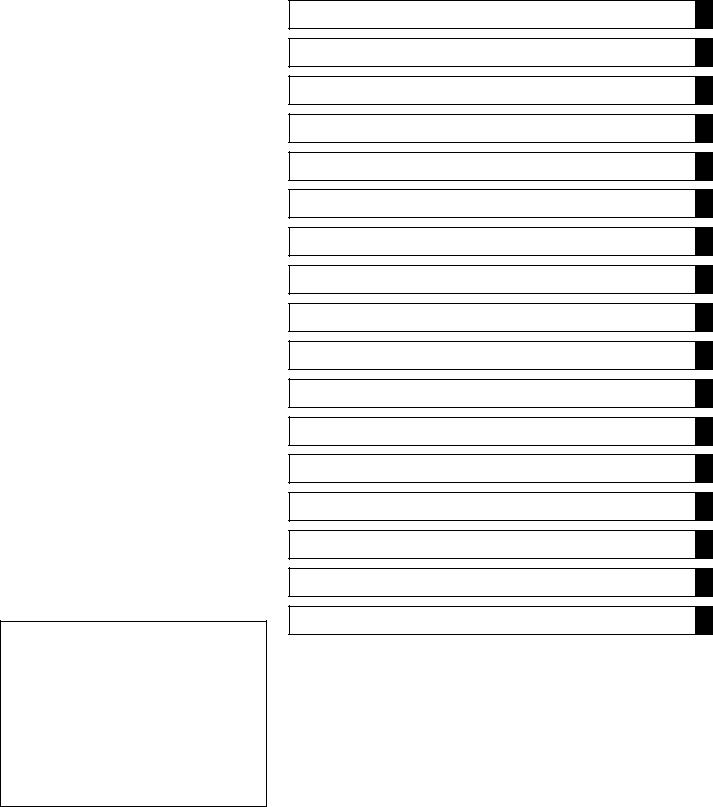
Battery Ground
Before completing any service on the motorcycle, disconnect the battery wires from the battery to prevent the engine from accidentally turning over. Disconnect the ground wire (−) first and then the positive (+). When completed with the service, first connect the positive (+) wire to the positive (+) terminal of the battery then the negative (−) wire to the negative terminal.
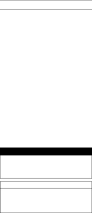
Edges of Parts
Lift large or heavy parts wearing gloves to prevent injury from possible sharp edges on the parts.
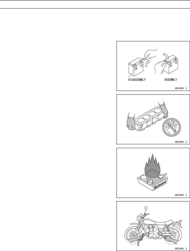
Solvent
Use a high flush point solvent when cleaning parts. High flush point solvent should be used according to directions of the solvent manufacturer.
Cleaning vehicle before disassembly
Clean the vehicle thoroughly before disassembly. Dirt or other foreign materials entering into sealed areas during vehicle disassembly can cause excessive wear and decrease performance of the vehicle.
GENERAL INFORMATION 1-3
Before Servicing
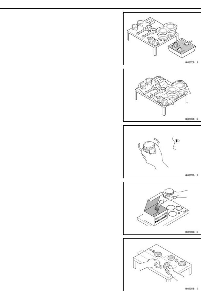
Arrangement and Cleaning of Removed Parts
Disassembled parts are easy to confuse. Arrange the parts according to the order the parts were disassembled and clean the parts in order prior to assembly.
Storage of Removed Parts
After all the parts including subassembly parts have been cleaned, store the parts in a clean area. Put a clean cloth or plastic sheet over the parts to protect from any foreign materials that may collect before re-assembly.
Inspection
Reuse of worn or damaged parts may lead to serious accident. Visually inspect removed parts for corrosion, discoloration, or other damage. Refer to the appropriate sections of this manual for service limits on individual parts. Replace the parts if any damage has been found or if the part is beyond its service limit.
Replacement Parts
Replacement Parts must be KAWASAKI genuine or recommended by KAWASAKI. Gaskets, O rings, Oil seals, Grease seals, circlips or cotter pins must be replaced with new ones whenever disassembled.
Assembly Order
In most cases assembly order is the reverse of disassembly, however, if assembly order is provided in this Service Manual, follow the procedures given.
1-4 GENERAL INFORMATION
Before Servicing
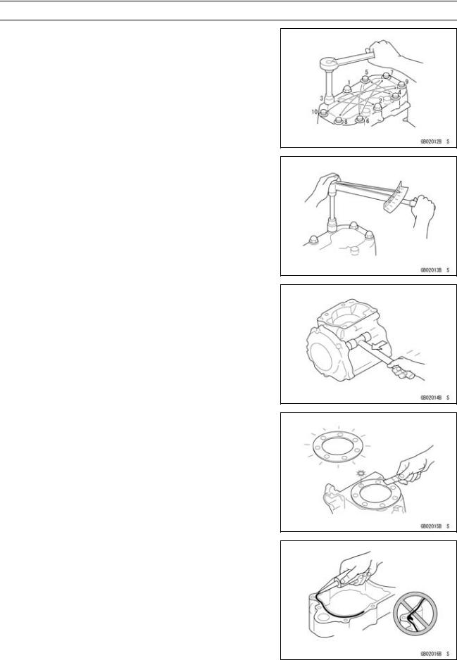
Tightening Sequence
Bolts, nuts, or screws must be tightened according to the specified sequence to prevent case warpage or deformation which can lead to malfunction. If the specified tightening sequence is not indicated, tighten the fasteners alternating diagonally.
Tightening Torque
Incorrect torque applied to a bolt, nut, or screw may lead to serious damage. Tighten fasteners to the specified torque using a good quality torque wrench. Often, the tightening sequence is followed twice-initial tightening and final tightening with torque wrench.
Force
Use common sense during disassembly and assembly, excessive force can cause expensive or hard to repair damage. When necessary, remove screws that have a non -permanent locking agent applied using an impact driver. Use a plastic-faced mallet whenever tapping is necessary.
Gasket, Oring
Hardening, shrinkage, or damage of both gaskets and O-rings after disassembly can reduce sealing performance. Remove old gaskets and clean the sealing surfaces thoroughly so that no gasket material or other material remains. Install new gaskets and replace used O-rings when re-assembling
Liquid Gasket, Locking Agent
For applications that require Liquid Gasket or a Locking agent, clean the surfaces so that no oil residue remains before applying liquid gasket or locking agent. Do not apply them excessively. Excessive application can clog oil passages and cause serious damage.
GENERAL INFORMATION 1-5
Before Servicing
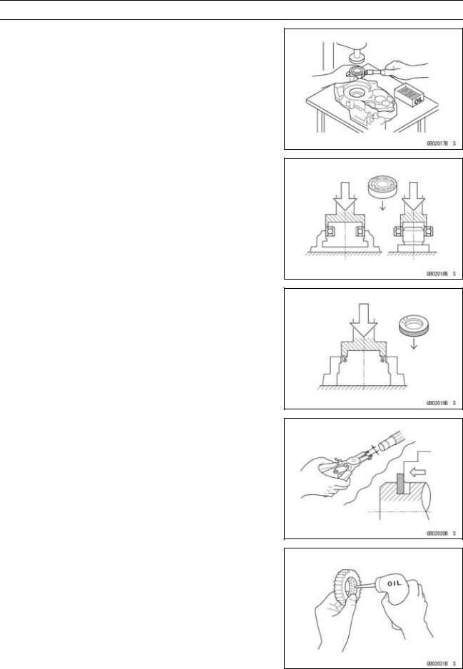
Press
For items such as bearings or oil seals that must be pressed into place, apply small amount of oil to the contact area. Be sure to maintain proper alignment and use smooth movements when installing.
Ball Bearing and Needle Bearing
Do not remove pressed ball or needle unless removal is absolutely necessary. Replace with new ones whenever removed. Press bearings with the manufacturer and size marks facing out. Press the bearing into place by putting pressure on the correct bearing race as shown.
Pressing the incorrect race can cause pressure between the inner and outer race and result in bearing damage.
Oil Seal, Grease Seal
Do not remove pressed oil or grease seals unless removal is necessary. Replace with new ones whenever removed. Press new oil seals with manufacture and size marks facing out. Make sure the seal is aligned properly when installing.
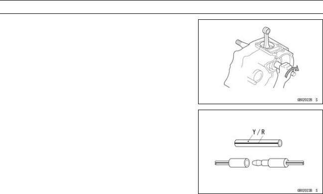
Circlips, Cotter Pins
Replace circlips or cotter pins that were removed with new ones. Install the circlip with its sharp edge facing outward and its chamfered side facing inward to prevent the clip from being pushed out of its groove when loaded. Take care not to open the clip excessively when installing to prevent deformation.
Lubrication
It is important to lubricate rotating or sliding parts during assembly to minimize wear during initial operation. Lubrication points are called out throughout this manual, apply the specific oil or grease as specified.
1-6 GENERAL INFORMATION
Before Servicing
Direction of Engine Rotation
When rotating the crankshaft by hand, the free play amount of rotating direction will affect the adjustment. Rotate the crankshaft to positive direction (clockwise viewed from right side).
Electrical Wires
A two-color wire is identified first by the primary color and then the stripe color. Unless instructed otherwise, electrical wires must be connected to those of the same color.
GENERAL INFORMATION 1-7
Model Identification
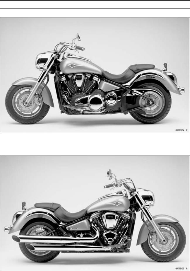
VN2000-A1 (US, and Canada) Left Side View:
VN2000-A1 (US, and Canada) Right Side View:
 User Manual")
1-8 GENERAL INFORMATION
Model Identification
VN2000-A1 (Europe) Left Side View:
VN2000-A1 (Europe) Right Side View:
|
GENERAL INFORMATION 1-9 |
|||
|
General Specifications |
|||
|
Items |
VN2000-A1 |
||
|
Dimensions: |
|||
|
Overall length |
2 535 mm (99.80 in.) |
||
|
Overall width |
1 025 mm (40.35 in.), (AU) 985 mm (38.8 in.) |
||
|
Overall height |
1 155 mm (45.47 in.) |
||
|
Wheelbase |
1 735 mm (68.31 in.) |
||
|
Road clearance |
135 mm (5.32 in.) |
||
|
Seat height |
680 mm (26.8 in.) |
||
|
Dry mass |
340 kg (750 lb) |
||
|
Curb mass: |
Front |
176 kg (388 lb) |
|
|
Rear |
195 kg (429 lb) |
||
|
Fuel tank capacity |
21 L (5.5 US gal) |
||
|
Fuel |
Unleaded and high-octane gasoline |
||
|
(see VN2000-A1 Owner’s Manual) |
|||
|
Performance: |
|||
|
Minimum turning radius |
3.2 m (10.5 ft) |
||
|
Engine: |
|||
|
Type |
4-stroke, OHV, V2-cylinder |
||
|
Cooling system |
Liquid-cooled |
||
|
Bore and stroke |
103 × 123.2 mm (4.06 × 4.850 in.) |
||
|
Displacement |
2 053 mL (125.3 cu in.) |
||
|
Compression ratio |
9.5 : 1 |
||
|
Maximum horsepower |
76 kW (103 PS) @4 800 r/min (rpm), (CA) (CAL) (US) – |
||
|
Maximum torque |
177 N·m (18.05 kgf·m, 130.6 ft·lb) @3 200 r/min (rpm), |
||
|
(CA) (CAL) (US) – |
|||
|
Carburetion system |
DFI (Digital Fuel Injection) System |
||
|
Starting system |
Electric starter |
||
|
Ignition system |
Battery and coil (transistorized) |
||
|
Timing advance |
Electronically advanced (digital) |
||
|
Ignition timing |
Front |
From 13° BTDC @900 r/min (rpm) ~ 51° BTDC |
|
|
@4 000 r/min (rpm) |
|||
|
Rear |
From 15° BTDC @900 r/min (rpm) ~ 51° BTDC |
||
|
@4 000 r/min (rpm) |
|||
|
Spark plugs |
NGK IZFR6F-11 |
||
|
Cylinder numbering method |
Front to Rear, 1-2 |
||
|
Firing order |
1-2 |
||
|
Valve timing: |
|||
|
Inlet |
Open |
39° BTDC |
|
|
Close |
69° ABDC |
||
|
Duration |
288° |
||
|
Exhaust |
Open |
69° BBDC |
|
|
Close |
39° ATDC |
||
|
Duration |
288° |
||
|
Lubrication system |
Forced lubrication (semi-dry sump) |
||
|
Engine oil: |
Type |
API SE, SF or SG class |
|
|
Viscosity |
API SH or SJ class with JASO MA |
||
|
SAE10W-40 |
|||
|
Capacity |
5.5 L (5.8 US qt, when engine is completely disassembled |
||
|
and dry) |
|||

1-10 GENERAL INFORMATION
General Specifications
|
Items |
VN2000-A1 |
||
|
Drive Train: |
|||
|
Primary reduction system: |
|||
|
Type |
Chain |
||
|
Reduction ratio |
|||
|
1.500 (48/32) |
|||
|
Clutch type |
Wet multi disc |
||
|
Transmission: |
|||
|
Type |
5-speed, constant mesh, return shift |
||
|
Gear ratios: |
1st |
2.550 (51/20) |
|
|
2nd |
1.629 (44/27) |
||
|
3rd |
1.218 (39/32) |
||
|
4th |
0.939 (31/33) |
||
|
Final drive system: |
5th |
0.729 (27/37) |
|
|
Type |
Belt |
||
|
Reduction ratio |
2.744 (50/40 × 72/32), (EU) 2.455 (48/44 × 72/32) |
||
|
Overall drive ratio |
3.003 @ Top gear, (EU) 2.687 @ Top gear |
||
|
Frame: |
|||
|
Type |
|||
|
Tubular, double cradle |
|||
|
Caster (rake angel) |
32° |
||
|
Trail |
182 mm (7.17 in.) |
||
|
Front tire: |
Type |
Tubeless |
|
|
Rear tire: |
Size |
150/80 — R16MC 71V |
|
|
Type |
Tubeless |
||
|
Front suspension: |
Size |
200/60 — R16MC 79V |
|
|
Type |
Telescopic fork |
||
|
Wheel travel |
150 mm (5.91 in.) |
||
|
Rear suspension: |
Type |
Swingarm with mono-shock (non-link type) |
|
|
Wheel travel |
100 mm (3.94 in.) |
||
|
Brake Type: |
Front |
Dual disc |
|
|
Rear |
Single disc |
||
|
Electrical Equipment: |
|||
|
Battery |
|||
|
Capacity |
12 V 18 Ah |
||
|
Headlight: |
Type |
Semi-sealed beam |
|
|
Bulb |
12 V 65 W (quartz-halogen) |
||
|
12 V 55 W (quartz-halogen) |
|||
|
Tail/brake light |
12 V 5/21 W |
||
|
Alternator: |
Type |
Three-phase AC |
|
|
Rated output |
38A × 14 V @5 000 r/min (rpm) |
||
|
Specifications are subject to change without notice, and may not apply to every country. |
|||
|
AU: Australia |
|||
|
CAL: California |
|||
|
CA: Canada |
|||
|
US: United States of America |
|||
|
EU: Europe |
![]()
GENERAL INFORMATION 1-11
Technical Information – Oxygen Sensor
Overview
Kawasaki has adopted an oxygen sensor [A] for the European and California models in addition to the secondary air injection system and honeycomb catalyst. This helps Kasawaki keep the motorcycle with cleaner exhaust gas and cope with the emission regulations.
The oxygen sensor [A] is mounted above the exhaust manifold [B], whereas the honeycomb catalyst is located inside the silencer in the downstream of the exhaust gas.
The oxygen sensor uses the substance called zirconia (ZrO2). The electromotive force varies depending on the density of the oxygen. The sensor measures the oxygen density of the exhaust gas to detect whether the air/fuel mixture is lean or rich in relation to the optimum air/fuel mixture.
When the ECU is in the oxygen sensor feedback mode, it controls combustion by making the fuel injection amount of the injector rich or lean through the signal from the sensor.
1-12 GENERAL INFORMATION
Technical Information – Oxygen Sensor
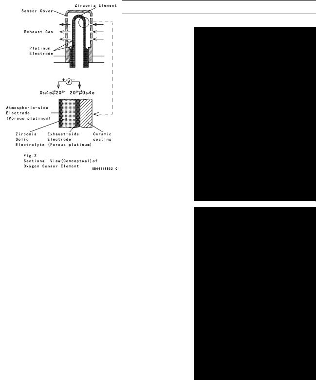
Construction and Operation
The oxygen sensor uses, a solid electrolyte called zirconia.
An electrolyte is a substance that has positive (+) and negative (−) ions and can move freely in a liquid.
For explanation purposes, picture a solid electrolyte plate as a wall and chambers A and B are divided by this wall. If both sides of the wall have platinum electrodes with holes, the difference in oxygen density (weight) between chambers A and B will move the oxygen from the chamber of higher oxygen density to the chamber of lower oxygen density until the two chambers are about equal in density. What actually moves are the oxygen ions (−) through the wall of the solid electrolyte.
The higher-density-side chamber will receive the “Pt” electrode surface with holes on the solid electrolyte wall and will become minus the oxygen ions (O2−). At this point, the O2− ions reach the “Pt” electrode of the opposite side.
Since the result of this O2− move also brings movement of “e−” (just like “cells” work in a battery), voltage will be built within the sensor.
The (conceptual) sectional view of the actual element in the oxygen sensor is shown. The sensor is exposed to exhaust gas. The shape of the sensor is tubular since the atmospheric side and exhaust gas side are parted by the wall. That means that the inside of this tubular solid electrolyte is the atmosphere side (higher oxygen density), and the outside of the tube faces the exhaust gas. The outside surface, which is in the stream of exhaust gases, has a coated layer of porous ceramic. Voltage is generated and can be measured because of the difference in oxygen density (positive and negative ions).
GENERAL INFORMATION 1-13
Technical Information – Oxygen Sensor
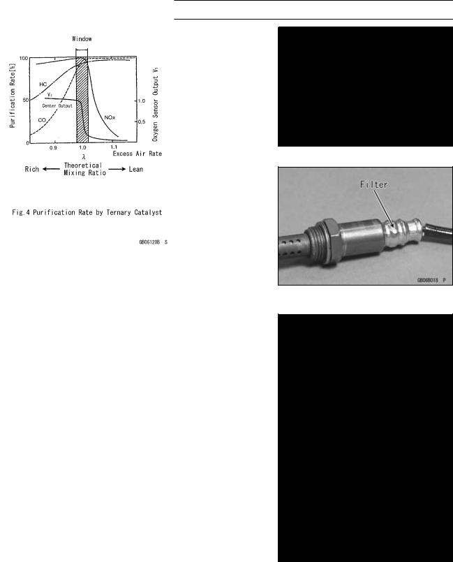
The sensor, uses the fresh air as the oxygen reference, and consists of a passageway to lead the fresh air inside the tubular element. Installed in this passageway is, a air permeable filter that allows the fresh air to pass through, but won’t allow moisture through. This keeps the sensor in touch with the atmosphere.
At a normal temperature, Zirconia (solid electrolyte) is an insulator and not able to sense the gases. Since the exhaust gas temperature does not become hot instantly, it takes sometime before the sensor starts to work. To solve the problem of the slow temperature increase of exhaust gases (which warms the electrolyte element), a built -in heater located inside the tubular element increases the temperature of the sensor so it can operate at a low exhaust gas temperature. Furthermore this built-in heater helps keep the sensor at a constant temperature.
Air/Fuel Ratio Control By Oxygen Sensor
”λ=1” indicates the optimum air/fuel ratio point, meaning the air/fuel ratio at which optimum (complete) combustion can be obtained. In the proximity of this mixture, the purification efficiency of the catalyst will be maximized.
The purification ratio of the three kinds of gas, HC (hydrocarbons), CO (carbon monoxide), Nox (nitrogen oxides) using the ternary (three) catalyst is shown in Fig. 4.
The best purification rate is at the zone where the oxygen sensor’s signal shows the sharp changes. This zone is called the “window” and if the oxygen sensor signal moves back and forth between the rich side (fuel rich) and lean side (fuel lean) from the oprimum mix ratio (but still within the width of the window), it indicates that the exhaust gas is in a good purification rate zone.
1-14 GENERAL INFORMATION
Technical Information – Oxygen Sensor
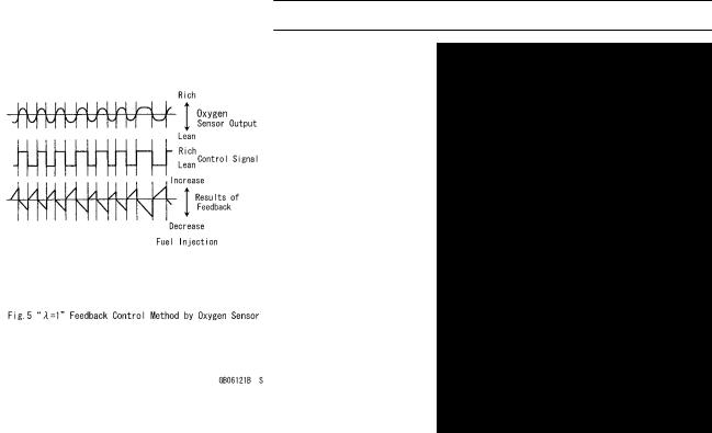
Figure 5 shows how the sensor operates the controlling factors.
There is a sharp voltage drop of about 1V (in reality, about 0.9 V) the sensor uses for control (a standard reference). By utilizing this voltage and using 0.45 V as the reference line, an output larger than the line indicates that exhaust gas is in the lean zone. So, when the system senses a “rich” condition through the sensor’s output voltage, it controls the fuel injection amount to make the fuel gradually leaner. When it reaches a leaner point, the sensor voltage signal drops sharply at the proximity λ=1 and goes below 0.45V. The system, at this level, senses that it has changed to “lean” and reverse the voltage signal to make the fuel richer. It then controls the fuel injection amount to make the fuel gradually richer. When it drops to a richer point, the signal drops sharply at the proximity λ=1 and goes over 0.45V. The system, at this level, senses that it has changed to “rich” and reverse the signal to make the fuel leaner. By having the signal repeat back and forth between the rich and lean sides, it can constantly stay within the window of the good purification rates. Thereby the oxygen sensor, works as a combustion control sensor for the optimum air/fuel ratio.

GENERAL INFORMATION 1-15
Technical Information – Oxygen Sensor
Maintenance
1)Periodic Inspections
Periodic inspections or special maintenance is not required for the sensor.
2)Oxygen Sensor Removal and Installation
Handle the oxygen sensor with care. Be careful not to damage sensor wires. Do not service the oxygen sensor while it is hot and not use an inpact wrench while removing or installing the oxygen sensor.
Avoid the fouling (damaging) of the sensing part of the sensor with foreign substances such as coolant, battery fluid, anti-corrosion fluid, and brake fluid.
Stop using the sensor if it is fouled with these substances.
Also stop using the sensor if the head part of the sensor (exposed to the atmosphere) is fouled. Since the sensor has a filter that allows air to escape but stop water, fouling of the sensor head may clog this filter.
Being subjected to a flame is also unacceptable for the sensor with the same reason as above.
3)Condition of the Sensor
Perform resistance measurements and visually check for scars, bends, and clogging of the sensor filter.
4)If trouble with the sensor occurs, one of the following service codes will be displayed. Accordingly, follow the related procedures in the Service Manual for necessary maintenance.
|
Service Code |
Outline of trouble |
|
33 |
Oxygen sensor is not activated |
|
67 |
Heater trouble due to wiring short or open |
|
94 |
Oxygen sensor output voltage is incorrect |
1-16 GENERAL INFORMATION
Technical Information – Electric Solenoid Operated Decompressor
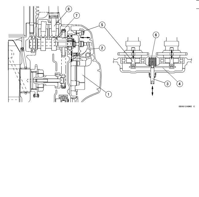
An automatic decompressor (Automatic Compression Reliese) system is installed to the right side of the engine. This decompressor is activated by an electric solenoid to make starting engine easy. When the ignition is switched on and the starter button depressed, the solenoid pulls a fulcrum-mounted link that depresses push rods in each camshaft.
The push rods activate the decompression mechanism to partially open the exhaust valves as the piston nears top dead center, releasing some of compression that can cause resistance during starting.
Releasing the starter button de-activates the solenoid and a spring returns the push rods to their normal operating position.
|
1. |
Decompression Solenoid |
5. |
Decompression Shaft |
|
|
2. |
Decompression Lever |
6. |
Spring |
|
|
3. Decompression Push Rod |
7. Exhaust Cam |
|||
|
4. |
Holder |
8. |
Push Rod |
GENERAL INFORMATION 1-17
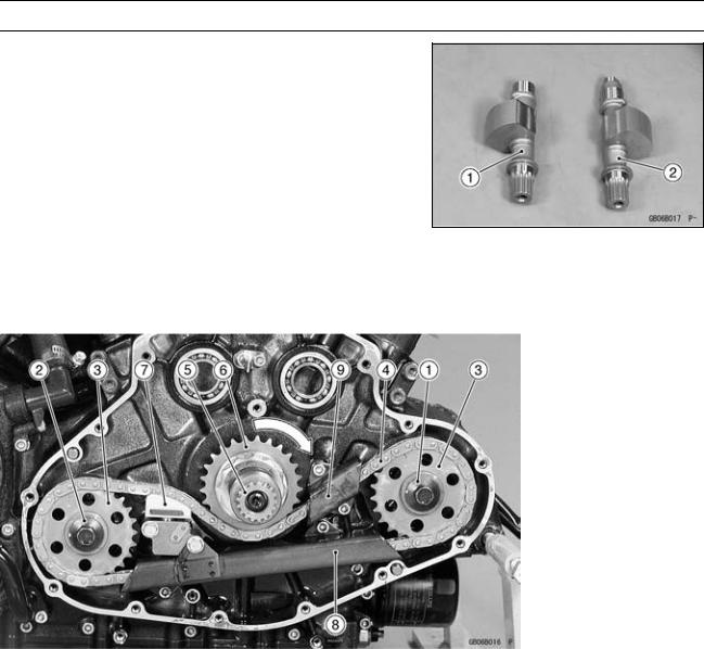
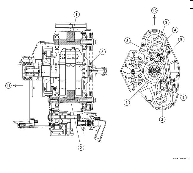
Technical Information – Dual Balancer Shaft System
Dual balancers harmonize primary balance and reduce vibration.
The VN2000-A1 engine applied two balancer shafts, one [1] is located in front of the front cylinder and another one [2] is behind the rear cylinder.
Each balancer shaft is driven by the chain which driven to the counterclockwise by crankshaft sprocket that rotate to the clockwise viewed from the righr side.
The hydraulically operated chain tensioner is located between crankshaft and rear balancer shaft.
The hydraulic chain tensioner is supplied the oil pressure from lubrication feed pump.
Two chain guides applied, one is between the crankshaft and front balancer shaft and another is under the crankshaft sprocket.
|
1. |
Front Balancer Shaft |
7. |
Hydraulic |
Chain |
Ten- |
|
|
2. |
Rear Balancer Shaft |
sioner |
||||
|
3. |
Front and Rear Balancer |
8. |
Chain |
Guide |
(under |
|
|
Sprocket |
Crankshaft) |
|||||
|
4. |
Balancer Drive Chain |
9. |
Chain |
Guide (between |
||
|
5. |
Crankshaft |
Crankshaft |
and |
Front |
||
|
6. |
Balancer Drive Sprocket |
Balancer Shaft) |
1-18 GENERAL INFORMATION
Technical Information – Dual Balancer Shaft System
|
1. |
Front Balancer Shaft |
6. |
Balancer Drive Sprocket |
9. |
Chain Guide (under |
||||
|
2. |
Rear Balancer Shaft |
7. |
Hydraulic |
Chain |
Ten- |
Crankshaft) |
|||
|
3. |
Front and Rear Balancer |
sioner |
10. |
Front |
|||||
|
Sprocket |
8. |
Chain Guide (between |
11. |
Left |
|||||
|
4. |
Balancer Drive Chain |
Crankshaft |
and |
Front |
|||||
|
5. |
Crankshaft |
Balancer Shaft) |
GENERAL INFORMATION 1-19
|
Unit Conversion Table |
|||||||||||||
Prefixes for Units: |
Units of Length: |
||||||||||||
|
km |
× |
0.6214 |
= |
mile |
|||||||||
|
Prefix |
Symbol |
Power |
|||||||||||
|
m |
× |
3.281 |
= |
ft |
|||||||||
|
mega |
M |
× 1 000 000 |
|||||||||||
|
mm |
× |
0.03937 |
= |
in. |
|||||||||
|
kilo |
k |
× |
1 000 |
||||||||||
|
centi |
c |
× |
0.01 |
||||||||||
|
milli |
m |
× |
0.001 |
Units of Torque: |
|||||||||
|
micro |
µ |
× 0.000001 |
|||||||||||
|
N·m |
× |
0.1020 |
= |
kgf·m |
|||||||||
|
N·m |
× |
0.7376 |
= |
ft·lb |
|||||||||
Units of Mass: |
N·m |
× |
8.851 |
= |
in·lb |
||||||||
|
kgf·m |
× |
9.807 |
= |
N·m |
|||||||||
|
kg |
× |
2.205 |
= |
lb |
kgf·m |
× |
7.233 |
= |
ft·lb |
||||
|
g |
× |
0.03527 |
= |
oz |
kgf·m |
× |
86.80 |
= |
in·lb |
||||
Units of Volume: |
Units of Pressure: |
||||||||||||
|
L |
× |
0.2642 |
= |
gal (US) |
kPa |
× |
0.01020 |
= |
kgf/cm² |
||||
|
L |
× |
0.2200 |
= |
gal (imp) |
kPa |
× |
0.1450 |
= |
psi |
||||
|
L |
× |
1.057 |
= |
qt (US) |
kPa |
× |
0.7501 |
= |
cm Hg |
||||
|
L |
× |
0.8799 |
= |
qt (imp) |
kgf/cm² |
× |
98.07 |
= |
kPa |
||||
|
L |
× |
2.113 |
= |
pint (US) |
kgf/cm² |
× |
14.22 |
= |
psi |
||||
|
L |
× |
1.816 |
= |
pint (imp) |
cm Hg |
× |
1.333 |
= |
kPa |
||||
|
mL |
× |
0.03381 |
= |
oz (US) |
|||||||||
|
mL |
× |
0.02816 |
= |
oz (imp) |
Units of Speed: |
||||||||
|
mL |
× |
0.06102 |
= |
cu in. |
|||||||||
|
km/h |
× |
0.6214 |
= |
mph |
|||||||||
Units of Force: |
Units of Power: |
||||||||||||
|
N |
× |
0.1020 |
= |
kgf |
|||||||||
|
N |
× |
0.2248 |
= |
lb |
kW |
× |
1.360 |
= |
PS |
||||
|
kg |
× |
9.807 |
= |
N |
|||||||||
|
kW |
× |
1.341 |
= |
HP |
|||||||||
|
kg |
× |
2.205 |
= |
lb |
PS |
× |
0.7355 |
= |
kW |
||||
|
PS |
× |
0.9863 |
= |
HP |
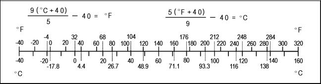
Units of Temperature:
![]()
PERIODIC MAINTENANCE 2-1
Periodic Maintenance
Table of Contents
|
Periodic Maintenance Chart ………….. |
2-2 |
Headlight Aiming Inspection …….. |
|
Torque and Locking Agent…………….. |
2-5 |
Side Stand Switch Operation |
|
Specifications ……………………………… |
2-11 |
Inspection……………………………. |
|
Special Tools ………………………………. |
2-13 |
Engine Stop Switch Operation |
|
Periodic Maintenance Procedures….. |
2-14 |
Inspection……………………………. |
|
Steering System: ………………………. |
2-14 |
Fuel System (DFI):…………………….. |
|
Steering Play Inspection ………….. |
2-14 |
Throttle Control System |
|
Steering Play Adjustment…………. |
2-14 |
Inspection……………………………. |
|
Steering Stem Bearing |
Idle Speed Inspection ……………… |
|
|
Lubrication…………………………… |
2-15 |
Fuel Hose and Connection |
|
Brake System: ………………………….. |
2-15 |
Inspection……………………………. |
|
Brake Fluid Leak (Brake Hose |
Cooling System…………………………. |
|
|
and Pipe)…………………………….. |
2-15 |
Coolant Level Inspection………….. |
|
Brake Hose Damage and |
Radiator Hose and Connection |
|
|
Installation Connection |
Inspection……………………………. |
|
|
Inspection……………………………. |
2-16 |
Evaporative Emission Control |
|
Brake Operation Inspection ……… |
2-16 |
System Inspection(CAL): …………. |
|
Brake Fluid Level Inspection…….. |
2-16 |
Evaporative Emission Control |
|
Brake Pad Wear Inspection ……… |
2-17 |
System Inspection………………… |
|
Brake Light Switch Operation …… |
2-17 |
Air Suction System: …………………… |
|
Wheel and Tires:……………………….. |
2-18 |
Air Switching Valve Operation |
|
Tire Air Pressure Inspection……… |
2-18 |
Test…………………………………….. |
|
Wheel/Tire Damage Inspection…. |
2-18 |
Others:…………………………………….. |
|
Tire Tread Wear Inspection………. |
2-18 |
Chassis Parts Lubrication ………… |
|
Wheel Bearing Damage |
Bolts and Nuts Tightness |
|
|
Inspection……………………………. |
2-19 |
Inspection……………………………. |
|
Suspensions …………………………….. |
2-19 |
Replacement Parts: …………………… |
|
Front Forks/Rear Shock Absorber |
Brake Hose and Pipe |
|
|
Operation Inspection …………….. |
2-19 |
Replacement……………………….. |
|
Front Fork Oil Leak Inspection….. |
2-20 |
Brake Fluid Change ………………… |
|
Rear Shock Absorber Oil Leak |
Master Cylinder Rubber Parts |
|
|
Inspection …………………………… |
2-20 |
Replacement……………………….. |
|
Swingarm Pivot Lubrication ……… |
2-20 |
Caliper Rubber Parts |
|
Clutch and Drive Train: ………………. |
2-21 |
Replacement……………………….. |
|
Clutch Operation …………………….. |
2-21 |
Spark Plug Replacement …………. |
|
Belt Deflection Inspection ……….. |
2-21 |
Air Cleaner Element |
|
Belt Deflection Adjustment……….. |
2-23 |
Replacement……………………….. |
|
Wheel Alignment |
Engine Oil Change………………….. |
|
|
Inspection/Adjustment…………… |
2-24 |
Oil Filter Replacement …………….. |
|
Belt Wear and Damage |
Fuel Hose Replacement ………….. |
|
|
Inspection……………………………. |
2-25 |
Coolant Change ……………………… |
|
Electrical System: ……………………… |
2-27 |
Radiator Hose and O-ring |
|
Spark Plug Condition Inspection.. |
2-27 |
Replacement……………………….. |
|
Lights and Switches Operation …. |
2-28 |
2 
2-30
2-31
2-32
2-32
2-32
2-33
2-33
2-34
2-34
2-34
2-35
2-35
2-36
2-36
2-36
2-36
2-37
2-39
2-39
2-39
2-41
2-42
2-45
2-46
2-47
2-49
2-49
2-50
2-53

2-2 PERIODIC MAINTENANCE
Periodic Maintenance Chart
The scheduled maintenance must be done in accordance with this chart to keep the motorcycle in good running condition.The initial maintenance is vitally important and must not be neglected.
Periodic Inspection:
|
FREQUENCY |
Whichever |
* ODOMETER READING |
|||||||||||
|
comes |
× 1000 km |
||||||||||||
|
first |
( × 1000 mile) |
||||||||||||
|
1 |
6 |
12 |
18 |
24 |
30 |
36 |
See |
||||||
|
INSPECTION |
Every |
(0.6) |
(4) |
(7.5) |
(12) |
(15) |
(20) |
(24) |
Page |
||||
|
Steering System: |
|||||||||||||
|
Steering play — inspect |
year |
• |
• |
• |
• |
2–14 |
|||||||
|
• |
|||||||||||||
|
Steering stem bearing — lubricate |
2 year |
2–15 |
|||||||||||
|
Brake System: |
|||||||||||||
|
Brake fluid leak (brake hose and pipe)- |
year |
• |
• |
• |
• |
• |
• |
• |
2–15 |
||||
|
inspect |
|||||||||||||
|
Brake hose damage — inspect |
year |
• |
• |
• |
• |
• |
• |
• |
2–16 |
||||
|
Brake hose installation condition — inspect |
year |
• |
• |
• |
• |
• |
• |
• |
2–16 |
||||
|
Brake operation (effectiveness, no drag) — |
year |
• |
• |
• |
• |
• |
• |
• |
2–16 |
||||
|
inspect |
|||||||||||||
|
Brake fluid level — inspect |
6 month |
• |
• |
• |
• |
• |
• |
• |
2–16 |
||||
|
Brake pad wear — inspect # |
• |
• |
• |
• |
• |
• |
2–17 |
||||||
|
Brake light switch operation — inspect |
• |
• |
• |
• |
• |
• |
• |
2–17 |
|||||
|
Wheels and Tires: |
|||||||||||||
|
Tire air pressure — inspect |
year |
• |
• |
• |
2–18 |
||||||||
|
Wheel/tire damage — inspect |
• |
• |
• |
2–18 |
|||||||||
|
Tire tread wear, abnormal wear — inspect |
• |
• |
• |
2–18 |
|||||||||
|
Wheel bearing damage — inspect |
year |
• |
• |
• |
2–19 |
||||||||
|
Suspensions: |
|||||||||||||
|
Front forks/rear shock absorber operation |
• |
• |
• |
2–19 |
|||||||||
|
(smooth stroke) — inspect |
|||||||||||||
|
Front forks/rear shock absorber oil leak — |
year |
• |
• |
• |
2–20 |
||||||||
|
inspect |
|||||||||||||
|
• |
|||||||||||||
|
Swingarm pivot — lubrication |
2–20 |
||||||||||||
|
Clutch and Drive Train: |
|||||||||||||
|
Clutch operation (play, disengagement, |
• |
• |
• |
• |
2–21 |
||||||||
|
engagement) — inspect |
|||||||||||||
|
Belt deflection — inspect |
• |
• |
• |
• |
• |
• |
• |
2–21 |
|||||
|
Belt wear and damage — inspect |
• |
• |
• |
• |
• |
• |
• |
2–24 |
|||||
|
Electrical System: |
|||||||||||||
|
Spark plug condition — Inspect |
• |
• |
• |
2–27 |
|||||||||
|
Lights and switches operation — inspect |
year |
• |
• |
• |
2–28 |
||||||||
|
Headlight aiming — inspect |
year |
• |
• |
• |
2–30 |
||||||||
|
Side stand switch operation — inspect |
year |
• |
• |
• |
2–31 |
||||||||
|
Engine stop switch operation — inspect |
year |
• |
• |
• |
2–32 |

PERIODIC MAINTENANCE 2-3
Periodic Maintenance Chart
|
FREQUENCY |
Whichever |
* ODOMETER READING |
|||||||||||
|
comes |
× 1000 km |
||||||||||||
|
first |
( × 1000 mile) |
||||||||||||
|
1 |
6 |
12 |
18 |
24 |
30 |
36 |
See |
||||||
|
INSPECTION |
Every |
(0.6) |
(4) |
(7.5) |
(12) |
(15) |
(20) |
(24) |
Page |
||||
|
Fuel System: |
|||||||||||||
|
Throttle control system (play, smooth |
year |
• |
• |
• |
• |
2–32 |
|||||||
|
return, no drag) — inspect |
|||||||||||||
|
Idle speed — inspect |
• |
• |
• |
• |
2–33 |
||||||||
|
Fuel leak (fuel hose and pipe) — inspect |
year |
• |
• |
• |
• |
2–33 |
|||||||
|
Fuel hoses and pipe damage — inspect |
year |
• |
• |
• |
• |
2–33 |
|||||||
|
Fuel hoses and pipe installation condition |
year |
• |
• |
• |
• |
2–33 |
|||||||
|
— inspect |
|||||||||||||
|
Cooling System: |
|||||||||||||
|
Coolant level — inspect |
• |
• |
• |
• |
2–34 |
||||||||
|
Coolant leak (radiator hose and pipe) — |
year |
• |
• |
• |
• |
2–34 |
|||||||
|
inspect |
|||||||||||||
|
Radiator hose and pipe damage — inspect |
year |
• |
• |
• |
• |
2–34 |
|||||||
|
Radiator hose and pipe installation |
year |
• |
• |
• |
• |
2–34 |
|||||||
|
condition — inspect |
|||||||||||||
|
Evaporative Emission Control System |
|||||||||||||
|
(CAL): |
|||||||||||||
|
Evaporative emission control system |
• |
• |
• |
• |
• |
• |
• |
2–35 |
|||||
|
function — inspect |
|||||||||||||
|
Air Suction System: |
|||||||||||||
|
Air suction system damage — inspect |
• |
• |
• |
2–36 |
|||||||||
|
Others: |
|||||||||||||
|
Chassis parts — lubricate |
year |
• |
• |
• |
2–36 |
||||||||
|
Bolts and nuts tightness — inspect |
• |
• |
• |
• |
2–37 |
||||||||
|
# : Service more frequently when operating in severe conditions; dusty, wet, muddy, high speed or |
|||||||||||||
|
frequent starting/stopping. |
|||||||||||||
|
* : For higher odometer readings, repeat at the frequency interval established here. |
|||||||||||||
|
(CAL): California |

2-4 PERIODIC MAINTENANCE
Periodic Maintenance Chart
Periodic Replacement Parts:
|
FREQUENCY |
Whichever |
* ODOMETER READING |
|||||||||
|
comes |
× 1000 km |
||||||||||
|
first |
( × 1000 mile) |
||||||||||
|
1 |
12 |
24 |
36 |
48 |
See |
||||||
|
CHANGE/REPLACE ITEM |
Every |
(0.6) |
(7.5) |
(15) |
(24) |
(30) |
Page |
||||
|
Brake hoses and pipes |
4 year |
• |
2–39 |
||||||||
|
Brake fluid |
2 year |
• |
• |
2–39 |
|||||||
|
Rubber parts of master cylinder and caliper |
4 year |
• |
2–41 |
||||||||
|
Spark plug |
• |
• |
2–45 |
||||||||
|
Air cleaner element # |
2–46 |
||||||||||
|
Engine oil # |
year |
• |
• |
• |
• |
• |
2–47 |
||||
|
Oil filter |
year |
• |
• |
• |
• |
• |
2–49 |
||||
|
Fuel hose |
4 year |
• |
• |
2–49 |
|||||||
|
Coolant |
3 year |
2–50 |
|||||||||
|
Radiator hose and O-ring |
3 year |
• |
2–53 |
||||||||
|
# : Service more frequently when operating in severe conditions; dusty, wet, muddy, high speed or |
|||||||||||
|
frequent starting/stopping. |
|||||||||||
|
* : For higher odometer readings, repeat at the frequency interval established here. |
|
PERIODIC MAINTENANCE 2-5 |
|||||||||||||
|
Torque and Locking Agent |
|||||||||||||
|
The following tables list the tightening torque |
The table below, relating tightening torque to |
||||||||||||
|
for the major fasteners requiring use of a non |
thread diameter, lists the basic torque for the |
||||||||||||
|
-permanent locking agent or liquid gasket. |
bolts and nuts. Use this table for only the bolts |
||||||||||||
|
and nuts which do not require a specific torque |
|||||||||||||
|
Letters used in the “Remarks” column mean: |
value. |
All of the values are for use with dry |
|||||||||||
|
L: Apply a non-permanent locking agent to |
solvent-cleaned threads. |
||||||||||||
|
the threads. |
Basic Torque for General Fasteners |
||||||||||||
|
G: Apply grease to the threads. |
|||||||||||||
|
Threads |
Torque |
||||||||||||
|
MO: Apply molybdenum disulfide grease oil |
|||||||||||||
|
solution. |
dia. (mm) |
N·m |
kgf·m |
ft·lb |
|||||||||
|
O: Apply oil to the threads and seating sur- |
5 |
3.4 ~ 4.9 |
0.35 ~ 0.50 |
30 ~ 43 in·lb |
|||||||||
|
face. |
6 |
5.9 ~ 7.8 |
0.60 ~ 0.80 |
52 ~ 69 in·lb |
|||||||||
|
S: Tighten the fasteners following the speci- |
|||||||||||||
|
8 |
14 ~19 |
1.4 ~1.9 |
10.0 ~ 13.5 |
||||||||||
|
fied sequence. |
|||||||||||||
|
10 |
25 ~ 34 |
2.6 ~ 3.5 |
19.0 ~ 25 |
||||||||||
|
SS: Apply silicone sealant. |
|||||||||||||
|
Si: Apply silicone grease (ex. PBC grease). |
12 |
44 ~ 61 |
4.5 ~ 6.2 |
33 ~ 45 |
|||||||||
|
R: Replacement parts |
|||||||||||||
|
14 |
73 ~ 98 |
7.4 ~ 10.0 |
54 ~ 72 |
||||||||||
|
Lh: Left-hand-threads |
16 |
115 ~ 155 |
11.5 ~ 16.0 |
83 ~ 115 |
|||||||||
|
St: Stake the fasteners to prevent loosening. |
|||||||||||||
|
18 |
165 ~ 225 |
17.0 ~ 23.0 |
125 ~ 165 |
||||||||||
|
AL: Tighten the two clamp bolts alternately |
|||||||||||||
|
20 |
225 ~ 325 |
23 ~ 33 |
165 ~ 240 |
||||||||||
|
two times to ensure even tightening |
|||||||||||||
|
torque. |
|||||||||||||
|
Fastener |
Torque |
Remarks |
|||||||||||
|
N·m |
kgf·m |
ft·lb |
|||||||||||
|
Fuel System: |
|||||||||||||
|
Fuel pump bolts |
9.8 |
1.0 |
87 |
in·lb |
S, L |
||||||||
|
Water temperature sensor |
12 |
1.2 |
104 in·lb |
||||||||||
|
Oxygen sensor |
44 |
4.5 |
33 |
||||||||||
|
Gear position switch mounting bolts |
6.9 |
0.70 |
61 |
in·lb |
|||||||||
|
Gear position switch lead clamp bolts |
6.9 |
0.70 |
61 |
in·lb |
|||||||||
|
Camshaft position sensor bolt |
9.8 |
1.0 |
87 |
in·lb |
L |
||||||||
|
Fuel level sensor mounting bolts |
6.9 |
0.70 |
61 |
in·lb |
L |
||||||||
|
Speed sensor mounting bolt |
9.8 |
1.0 |
87 |
in·lb |
L |
||||||||
|
Delivery joint bolts |
9.8 |
1.0 |
87 |
in·lb |
L |
||||||||
|
Throttle body assy holder bolts |
9.8 |
1.0 |
87 |
in·lb |
L |
||||||||
|
Inlet manifold bolts |
9.8 |
1.0 |
87 |
in·lb |
L |
||||||||
|
Air cleaner housing bolts |
9.8 |
1.0 |
87 |
in·lb |
|||||||||
|
Air cleaner housing Allen bolts |
9.8 |
1.0 |
87 |
in·lb |
|||||||||
|
Cooling System: |
|||||||||||||
|
Water temperature sensor |
12 |
1.2 |
104 in·lb |
||||||||||
|
Water pipe bolts |
9.8 |
1.0 |
87 |
in·lb |
|||||||||
|
Radiator fan bolts |
8.3 |
0.85 |
74 |
in·lb |
|||||||||
|
Reserve tank bolts |
6.9 |
0.70 |
61 |
in·lb |
|||||||||
|
Radiator cover bolts |
11 |
1.1 |
97 |
in·lb |
|||||||||
|
Water pump impeller bolt |
12 |
1.2 |
104 in·lb |
Lh |
|||||||||
|
Water pipe drain bolt |
9.8 |
1.0 |
87 |
in·lb |
|||||||||
|
Water pump air bleeder bolt |
7.8 |
0.80 |
69 |
in·lb |
|||||||||
|
Radiator screen screws |
6.9 |
0.70 |
61 |
in·lb |

2-6 PERIODIC MAINTENANCE
Torque and Locking Agent
|
Fastener |
Torque |
Remarks |
||||
|
N·m |
kgf·m |
ft·lb |
||||
|
Engine Top End: |
||||||
|
Rocker case cover bolts |
12 |
1.2 |
104 in·lb |
S, AL |
||
|
Rocker case bolts |
15 |
1.5 |
11 |
S |
||
|
Oil pipe banjo bolts |
||||||
|
54 |
5.5 |
40 |
||||
|
Oil pipe bolts |
9.8 |
1.0 |
87 |
in·lb |
||
|
Upper cylinder head nuts, φ 10 mm |
15 |
1.5 |
11 |
first, S, MO |
||
|
Upper cylinder head nuts, φ 10 mm |
29 |
3.0 |
21 |
final, S, MO |
||
|
Upper cylinder head nuts, φ 12 mm |
29 |
3.0 |
21 |
first, S, MO |
||
|
Upper cylinder head nuts, φ 12 mm |
88 |
9.0 |
65 |
final, S, MO |
||
|
Lower cylinder head nuts |
25 |
2.5 |
18 |
S |
||
|
Water jacket plugs |
22 |
2.2 |
16 |
L |
||
|
Water jacket plugs |
15 |
1.5 |
11 |
L |
||
|
Rocker shaft bolts |
12 |
1.2 |
104 in·lb |
|||
|
Cylinder mounting bolts |
25 |
2.5 |
18 |
L |
||
|
Coolant drain bolt |
9.8 |
1.0 |
87 |
in·lb |
||
|
Push rod cover bolts |
12 |
1.2 |
104 in·lb |
|||
|
Camshaft chain guide bolts |
12 |
1.2 |
104 in·lb |
L |
||
|
Camshaft chain tensioner bolts |
12 |
1.2 |
104 in·lb |
|||
|
Inner camshaft cover bolts |
12 |
1.2 |
104 in·lb |
|||
|
Stopper pin plug |
2.5 |
0.25 |
22 |
in·lb |
L |
|
|
Middle camshaft cover bolts |
12 |
1.2 |
104 in·lb |
|||
|
Middle camshaft cover bolts L 35 mm |
12 |
1.2 |
104 in·lb |
|||
|
Camshaft end cover bolts |
12 |
1.2 |
104 in·lb |
|||
|
Decompression solenoid bolts |
9.8 |
1.0 |
87 |
in·lb |
||
|
Outer camshaft cover bolts |
12 |
1.2 |
104 in·lb |
|||
|
Muffler bracket bolts |
||||||
|
25 |
2.5 |
18 |
||||
|
Muffler cover clamp screws |
6.9 |
0.7 |
61 |
in·lb |
||
|
Clutch: |
||||||
|
Primary chain upper guide bolts |
9.8 |
1.0 |
87 |
in·lb |
||
|
Primary chain lower guide bolts |
9.8 |
1.0 |
87 |
in·lb |
||
|
Cam damper bolt |
69 |
7.0 |
51 |
|||
|
Inner clutch cover bolts |
12 |
1.2 |
104 in·lb |
S, see text |
||
|
Outside plate bolt |
9.8 |
1.0 |
87 |
in·lb |
L |
|
|
Clutch hub nut |
135 |
14.0 |
101 |
MO |
||
|
Clutch spring bolts |
98 |
1.0 |
87 |
in·lb |
||
|
Outer clutch cover bolts |
12 |
1.2 |
104 in·lb |
S, see text |
||
|
Plug on outer clutch cover |
20 |
2.0 |
14 |
|||
|
Clutch cover oil drain plug |
||||||
|
21 |
2.1 |
15 |
||||
|
Clutch release lever bolt |
5.9 |
0.60 |
52 |
in·lb |
||
|
Starter lockout switch screw |
– |
– |
– |
L |
||
|
Inside plate bolt |
9.8 |
1.0 |
87 |
in·lb |
||

PERIODIC MAINTENANCE 2-7
Torque and Locking Agent
|
Fastener |
Torque |
Remarks |
||||
|
N·m |
kgf·m |
ft·lb |
||||
|
Engine Lubrication System: |
||||||
|
Rocker shaft oil pipe bolts |
87 |
in·lb |
||||
|
98 |
1.0 |
|||||
|
Cylinder head oil pipe banjo bolts |
54 |
5.4 |
40 |
|||
|
Oil filter |
||||||
|
17.5 |
1.75 |
12.5 |
||||
|
Oil passage bolt |
29 |
3.0 |
21 |
|||
|
Oil passage adapter drain plug |
in·lb |
|||||
|
9.8 |
1.0 |
87 |
||||
|
Relief valve |
15 |
1.5 |
11 |
L |
||
|
Camshaft oil pipe bolt |
in·lb |
|||||
|
9.8 |
1.0 |
87 |
||||
|
Oil pipe bolt L16 |
9.8 |
1.0 |
87 |
in·lb |
L |
|
|
Oil pipe bolt L30 |
104 in·lb |
|||||
|
12 |
1.2 |
|||||
|
Oil pump drive sprocket bolt |
29 |
3.0 |
21 |
|||
|
Oil pump chain tensioner bolt |
104 in·lb |
|||||
|
12 |
1.2 |
|||||
|
Oil pump cover bolts |
9.8 |
1.0 |
87 |
in·lb |
||
|
Inside plate bolt |
in·lb |
|||||
|
9.8 |
1.0 |
87 |
||||
|
Outside plate bolt |
9.8 |
1.0 |
87 |
in·lb |
L |
|
|
Clutch cover drain plug |
15 |
|||||
|
21 |
2.1 |
|||||
|
Oil pressure switch |
15 |
1.5 |
11 |
SS |
||
|
Oil passage adapter |
20 |
2.0 |
14 |
L |
||
|
Oil pan plug |
20 |
2.0 |
14 |
L |
||
|
Oil pipe stopper bolt |
in·lb |
|||||
|
6.9 |
0.7 |
61 |
||||
|
Oil screen bolt for crank room |
9.8 |
1.0 |
87 |
in·lb |
||
|
Oil pan bolts |
15 |
1.5 |
11 |
S |
||
|
Left oil pan drain plug |
20 |
2.0 |
14 |
|||
|
Right oil pan drain plug |
11 |
|||||
|
15 |
1.5 |
|||||
|
Engine Removal/Installation: |
||||||
|
Front downtube nuts |
88 |
9.0 |
65 |
S, AL |
||
|
Upper adjusting bolt |
9.8 |
1.0 |
87 |
in·lb |
S |
|
|
Lower adjusting bolt |
9.8 |
1.0 |
87 |
in·lb |
S |
|
|
Upper adjusting bolt locknut |
49 |
5.0 |
36 |
S |
||
|
Lower adjusting bolt locknut |
49 |
5.0 |
36 |
S |
||
|
Upper rear engine mounting nut |
59 |
6.0 |
43 |
S |
||
|
Lower rear engine mounting nut |
59 |
6.0 |
43 |
S |
||
|
Upper engine bracket nuts |
59 |
6.0 |
43 |
S, AL |
||
|
Upper engine mounting bolts |
44 |
4.5 |
33 |
S |
||
|
Lower engine bracket bolts |
59 |
6.0 |
43 |
S |
||
|
Front engine mounting nut |
44 |
4.5 |
33 |
S |
||
|
Rear downtube bolts14 |
108 |
11.0 |
80 |
S, AL |
||
|
Crankshaft/Transmission: |
||||||
|
Connecting rod big end bolts |
59 |
6.0 |
43 |
MO |
||
|
Balancer chain sprocket nut |
125 |
13.0 |
92.2 |
MO |
||
|
Camshaft chain sprocket bolt |
29 |
3.0 |
22 |
|||
|
Camshaft balancer gear bolts |
61 |
|||||
|
83 |
8.5 |

2-8 PERIODIC MAINTENANCE
Torque and Locking Agent
|
Fastener |
Torque |
Remarks |
|||||
|
N·m |
kgf·m |
ft·lb |
|||||
|
Upper balancer chain guide bolts |
12 |
1.2 |
104 in·lb |
||||
|
Lower balancer chain guide bolts |
12 |
1.2 |
104 in·lb |
||||
|
Balance chain tensioner bolts |
12 |
1.2 |
104 in·lb |
||||
|
Bearing retainer screws at output shaft |
6.9 |
0.7 |
61 |
in·lb |
|||
|
Bearing retainer bolts |
– |
– |
– |
L |
|||
|
Speed sensor bolt |
9.8 |
1.0 |
87 |
in·lb |
L |
||
|
Bearing retainer screws at pulley shaft |
6.9 |
0.7 |
61 |
in·lb |
|||
|
Crankcase bolts, φ |
8 |
29 |
3.0 |
22 |
S |
||
|
Crankcase bolts, φ |
6 |
12 |
1.2 |
104 in·lb |
S |
||
|
Outer transmission cover bolts |
12 |
1.2 |
104 in·lb |
S,see text |
|||
|
Inner transmission cover bolts |
12 |
1.2 |
104 in·lb |
S,see text |
|||
|
Transfer gear nut (Output shaft) |
196 |
20.0 |
145 |
MO, Lh |
|||
|
Transfer gear nut (Pulley shaft) |
78 |
8.0 |
58 |
MO |
|||
|
Gear set lever nut |
7.8 |
0.8 |
69 |
in·lb |
|||
|
Shift shaft return spring pin |
39 |
4.0 |
30 |
L |
|||
|
Rear shift lever bolt |
|||||||
|
25 |
2.5 |
18 |
|||||
|
Front shift lever clamp bolt |
25 |
2.5 |
18 |
||||
|
Shift dram cam bolt |
12 |
1.2 |
104 in·lb |
L |
|||
|
Rear shift rod locknut |
9.8 |
1.0 |
87 |
in·lb |
Lh |
||
|
Front shift rod locknut |
9.8 |
1.0 |
87 |
in·lb |
|||
|
Engine pulley mounting nut |
177 |
18 |
130 |
MO |
|||
|
Wheels/Tires: |
|||||||
|
Front axle nut |
127 |
13 |
94 |
||||
|
Front axle clamp bolts |
20 |
2.0 |
15 |
AL |
|||
|
Rear axle nut |
108 |
11 |
80 |
||||
|
Tire air valve nuts |
1.5 |
0.15 |
13 |
in·lb |
|||
|
Tire air valve cap |
0.15 |
0.015 |
1.3 in·lb |
||||
|
Final Drive: |
|||||||
|
Engine pulley inside cover bolts |
12 |
1.2 |
104 in·lb |
||||
|
Engine pulley mounting nut |
177 |
18 |
130 |
MO |
|||
|
Rear axle nut |
108 |
11 |
80 |
||||
|
Rear coupling stud bolts |
44 |
4.5 |
33 |
L |
|||
|
Ring screws |
6.9 |
0.70 |
61 |
in·lb |
|||
|
Rear pulley mounting nuts |
|||||||
|
69 |
7.0 |
51 |
|||||
|
Brakes: |
|||||||
|
Brake hose banjo bolts |
25 |
2.5 |
18 |
||||
|
Front brake reservoir cap screws |
1.5 |
0.15 |
13 |
in·lb |
|||
|
Brake lever pivot bolt |
1.0 |
0.10 |
8.7 in·lb |
Si |
|||
|
Brake lever pivot bolt locknut |
5.9 |
0.60 |
52 |
in·lb |
|||
|
Front brake light switch screw |
1.2 |
0.12 |
10 |
in·lb |
|||
|
Front master cylinder clamp bolts |
8.8 |
0.90 |
78 |
in·lb |
S |
||
|
Brake disc bolts |
27 |
2.8 |
20 |
L |

PERIODIC MAINTENANCE 2-9
Torque and Locking Agent
|
Fastener |
Torque |
Remarks |
|||
|
N·m |
kgf·m |
ft·lb |
|||
|
Front caliper mounting bolts |
25 |
2.5 |
18 |
||
|
Front caliper assembly bolts |
15 |
||||
|
21 |
2.1 |
||||
|
Front brake pad pins |
15 |
1.5 |
11 |
||
|
Caliper bleed valves |
69 in·lb |
||||
|
7.8 |
0.80 |
||||
|
Front brake pad spring bolts |
2.9 |
0.30 |
26 in·lb |
||
|
Rear master cylinder mounting bolts |
|||||
|
25 |
2.5 |
18 |
|||
|
Rear master cylinder push rod locknut |
17 |
1.7 |
12 |
||
|
Brake pedal clamp bolt |
|||||
|
25 |
2.5 |
18 |
|||
|
Rear caliper mounting bolts |
34 |
3.5 |
25 |
||
|
Suspension: |
|||||
|
Upper front fork clamp bolts |
20 |
2.0 |
15 |
||
|
Lower front fork clamp bolts |
34 |
3.5 |
25 |
AL |
|
|
Cover stopper bolts |
4.2 |
0.43 |
37 in·lb |
||
|
Front axle clamp bolts |
25 |
2.5 |
18 |
AL |
|
|
Front fork bottom Allen bolts |
23 |
2.3 |
17 |
L |
|
|
Rear shock absorber mounting bolt and nut |
|||||
|
59 |
6.0 |
43 |
|||
|
Swingarm pivot shaft nut |
127 |
13 |
94 |
||
|
Steering: |
|||||
|
Handlebar clamp bolts |
34 |
3.5 |
25 |
O, S |
|
|
Handlebar holder nuts |
|||||
|
34 |
3.5 |
25 |
|||
|
Steering stem head nut |
108 |
11 |
80 |
||
|
Upper front fork clamp bolts |
|||||
|
20 |
2.0 |
15 |
|||
|
Steering stem nut |
4.9 |
0.50 |
43 in·lb |
||
|
Lower front fork clamp bolts |
34 |
3.5 |
25 |
AL |
|
|
Frame: |
|||||
|
Front downtube nuts |
88 |
9.0 |
65 |
S |
|
|
Upper engine bracket nuts |
59 |
6.0 |
43 |
S |
|
|
Upper engine mounting bolts |
44 |
4.5 |
33 |
S |
|
|
Lower engine bracket bolts |
59 |
6.0 |
43 |
S |
|
|
Rear downtube bolts |
108 |
11 |
80 |
S |
|
|
Side stand mounting bolt |
44 |
4.5 |
33 |
S |
|
|
Side stand mounting nut |
44 |
4.5 |
33 |
S |
|
|
Adjust bolts |
9.8 |
1.0 |
87 in·lb |
S |
|
|
Footboard bracket bolts |
|||||
|
34 |
3.5 |
25 |
|||
|
Front engine mounting nut |
44 |
4.5 |
33 |
S |
|
|
Adjusting bolt locknuts |
49 |
5.0 |
36 |
S |
|
|
Rear engine mounting nuts |
59 |
6.0 |
43 |
S |
|
|
Side stand switch mounting bolt |
8.8 |
0.90 |
78 in·lb |
L |
|
|
Footpeg bracket bolts |
25 |
2.5 |
18 |
||
|
Muffler bracket mounting bolts |
|||||
|
25 |
2.5 |
18 |
|||
|
Electrical System: |
|||||
|
Spark plugs |
18 |
1.8 |
13 |

2-10 PERIODIC MAINTENANCE
Torque and Locking Agent
|
Fastener |
Torque |
Remarks |
||||
|
N·m |
kgf·m |
ft·lb |
||||
|
Alternator stator coil mounting bolts |
12 |
1.2 |
104 in·lb |
L |
||
|
Crankshaft sensor mounting bolts |
6.9 |
0.70 |
61 |
in·lb |
||
|
Oil pressure switch |
15 |
1.5 |
11 |
SS |
||
|
Speed sensor mounting bolt |
9.8 |
1.0 |
87 |
in·lb |
L |
|
|
Gear position switch mounting bolts |
4.9 |
0.50 |
43 |
in·lb |
L |
|
|
Gear position switch lead clamp bolts |
4.9 |
0.50 |
43 |
in·lb |
L |
|
|
Side stand switch mounting bolt |
8.8 |
0.90 |
78 |
in·lb |
L |
|
|
Regulator/rectifier bolts |
8.8 |
0.90 |
78 |
in·lb |
||
|
Oxygen sensor |
44 |
4.5 |
33 |
|||
|
Water temperature sensor |
12 |
1.2 |
104 in·lb |
|||
|
Camshaft position sensor bolt |
9.8 |
1.0 |
87 |
in·lb |
L |
|
|
Decompression solenoid bolts |
9.8 |
1.0 |
87 |
in·lb |
||
|
Starter lockout switch screw |
1.2 |
0.12 |
10 |
in·lb |
||
|
Front brake light switch screw |
1.2 |
0.12 |
10 |
in·lb |
||
|
Fuel level sensor mounting bolts |
6.9 |
0.70 |
61 |
in·lb |
L |
|
|
Fuel pump mounting bolts |
9.8 |
1.0 |
87 |
in·lb |
L, S |
|
|
Starter motor terminal nut |
9.8 |
1.0 |
87 |
in·lb |
||
|
Starter motor terminal locknut |
11 |
1.1 |
95 |
in·lb |
||
|
Starter motor mounting bolts |
9.8 |
1.0 |
87 |
in·lb |
||
|
Starter motor assembly bolts |
4.9 |
0.50 |
43 |
in·lb |
||
|
Turn signal light lens screws |
1.0 |
0.10 |
8.7 in·lb |
|||
|
Front turn signal light screws |
6.9 |
0.70 |
61 |
in·lb |
||
|
Tail/brake light unit mounting nuts |
5.9 |
0.60 |
52 |
in·lb |
||
|
Rear turn signal light screws |
6.9 |
0.70 |
61 |
in·lb |
||
|
License plate light lens mounting screws |
1.2 |
0.12 |
10 |
in·lb |
![]()
PERIODIC MAINTENANCE 2-11
Specifications
|
Item |
Standard |
Service Limit |
|
Fuel System (DFI): |
||
|
Throttle grip free play |
2 ~ 3 mm (0.08 ~ 0.12 in.) |
– – – |
|
Idle speed |
900 ± 50 r/min (rpm) |
– – – |
|
Air cleaner element |
Viscous paper element |
– – – |
|
Cooling System: |
||
|
Coolant: |
||
|
Type (recommended) |
Permanent type antifreeze |
– – – |
|
Color |
Green |
– – – |
|
Mixed ratio |
Soft water 50%, Coolant 50% |
– – – |
|
Freezing point |
–35°C (–31°F) |
– – – |
|
Total amount |
2.5 L (2.6 US qt) |
– – – |
|
Engine Top End: |
||
|
Valve clearance |
Non-adjustable (hydraulic lash adjusters) |
– – – |
|
Clutch: |
||
|
Clutch lever free play |
2 3 mm (0.08 0.12 in.) |
– – – |
|
Engine Lubrication System: |
||
|
Engine oil: |
||
|
Type |
API SE, SF or SG |
– – – |
|
API SH or SJ with JASO MA |
||
|
Viscosity |
SAE 10W-40 |
– – – |
|
Capacity |
4.4 L (4.7 US qt, when filter |
– – – |
|
is not removed) |
||
|
4.6 L (4.9 US qt, when filter |
– – – |
|
|
is removed) |
||
|
5.5 L (5.8 US qt, when engine |
– – – |
|
|
is completely disassembled and dry) |
||
|
Level |
Between upper and lower level lines |
– – – |
|
(Wait 2 ~ 3 minutes after idling |
||
|
or running) |
||
|
Tires: |
||
|
Tread depth: |
||
|
Front |
BRIDGESTONE BATTLAX BT020F |
1 mm (0.04 in.), |
|
4.3 mm (0.17 in.) |
(DE, AT, CH): 1.6 mm |
|
|
(0.063 in.) |
||
|
Rear |
BRIDGESTONE BATTLAX BT020R |
Up to 130 km/h (80 mph): |
|
7.0 mm (0.28 in.) |
2 mm (0.08 in.) |
|
|
Over 130km/h (80mph): |
||
|
3 mm (0.1 in.) |
||
|
Air pressure: (when cold) |
||
|
Front |
Up to 186 kg (410 lb) load: 250 kPa |
– – – |
|
(2.5 kgf/cm², 36 psi) |
||
|
Rear |
Up to 186 kg (410 lb) load: 290 kPa |
– – – |
|
(3.0 kgf/cm², 42 psi) |
||

2-12 PERIODIC MAINTENANCE
Specifications
|
Item |
Standard |
Service Limit |
||
|
Final Drive: |
||||
|
Drive belt deflection: |
– – – |
|||
|
(44.1 N, 4.5 kgf, 10 lb force) |
2.5 ~ 4.0 mm (0.10 ~ 0.16 in.) |
– – – |
||
|
when installing new belt or |
2.5 mm (0.10 in.) |
– – – |
||
|
engine remounted |
||||
|
Brakes: |
||||
|
Brake fluid |
||||
|
Grade |
DOT4 |
– – – |
||
|
Brake pad lining thickness: |
||||
|
Front |
4.0 mm (0.16 in.) |
1 mm (0.04 in.) |
||
|
Rear |
7.5 mm (0.30 in.) |
1 mm (0.04 in.) |
||
|
Brake light timing: |
||||
|
Front |
Pulled ON |
– – – |
||
|
Rear |
ON after about 10 mm (0.39 in.) of pedal |
– – – |
||
|
travel |
||||
|
Electrical System: |
||||
|
Spark plug |
IZFR6F-11 |
– – – |
||
|
Spark plug gap |
1.0 ~ 1.1 mm (0.039 ~ 0.043 in.) |
– – – |
||
|
AT: Republic of Austria |
||||
|
CH: Swiss Confederation |
||||
|
DE: Federal Republic of Germany |

|
PERIODIC MAINTENANCE 2-13 |
||
|
Special Tools |
||
|
Inside Circlip Pliers: |
Spark Plug Wrench, Hex 16: |
|
|
57001–143 |
57001–1262 |
Steering Stem Nut Wrench: 57001–1100
Jack Attachment : 57001–1571
|
Jack: |
Drive Belt Tension Gauge: |
|
|
57001–1238 |
57001– 1585 |
Oil Filter Wrench: 57001–1249

2-14 PERIODIC MAINTENANCE
Periodic Maintenance Procedures
Steering System:
Steering• Play Inspection
Check steering as follows.
○Use the jack [A] and jack attachment [B] under the frame pipe, and a commercially available jack [C] under the engine to lift the front wheel off the ground.
Special Tools — Jack: 57001-1238
Jack Attachment: 57001-1571
○With the front wheel pointing straight ahead, alternately tap each end of the handlebar. The front wheel should swing fully right and left from the force of gravity until the fork hits the stop.
If the wheel binds or catches before the stop, the steering is too tight.
○Feel for steering looseness by pushing and pulling [A] the fork.
 If you feel looseness, the steering is too loose.
NOTE
○The cables and wiring will have some effect on the motion of the fork which must be taken into account. Be sure the wires and cables are properly routed.
○The bearings must be in good condition and properly lubricated in order for any test to be valid.
Steering Play Adjustment
•Adjust the steering, if necessary. Remove:
Nacelle (see Frame chapter)
Handlebar (see Steering chapter)
Stem Head Nut [A]
• Washer
Loosen the upper fork clamp bolts on both sides.
•Remove:
O-ring [A]
Steering Stem Head [B]

PERIODIC MAINTENANCE 2-15
Periodic Maintenance Procedures
•Remove the claw washer.
•Adjust the stem nut [A] with the stem nut wrench [B] by tightening to the specified torque.
Special Tool — Steering Stem Nut Wrench: 57001-1100
•Torque — Steering Stem Nut: 4.9 N·m (0.50 kgf·m, 43 in·lb)
•Install the stem head.
Tighten the following in the order listed.
Torque — Stem Head Nut: 108 N·m (11 kgf·m, 80 ft·lb) Upper Fork Clamp Bolts: 20 N·m (2.0 kgf·m, 15
in·lb)
○Run the throttle cables, brake hose, and clutch cable in accordance with the Cable, Wire, and Hose Routing sec-
•tion in the Appendix chapter.
Check and adjust the steering and throttle cables after installation.

 WARNING
Do not attempt to ride the motorcycle until a full brake lever is obtained by pumping the brake lever until the pads are against the disc. The brakes will not function on the first application of the lever if this is not done.
Steering• Stem Bearing Lubrication
•Remove the steering stem. (see Steering chapter). Using a high-flash point solvent, wash the upper and lower tapered roller bearings [A] in the cages, and wipe the upper and lower outer races, which are press-fitted
•into the frame head pipe, clean of grease and dirt. Visually check the outer races and the rollers.
If the rollers or races are worn, or if either race is dented, replace both races and all the roller bearings as a set (see
•Steering chapter).
Pack the upper and lower tapered roller in the cages with grease, and apply a light coat of grease to the upper and
•lower outer races.
Install the steering stem, and adjust the steering (see
Steering chapter).
Brake System:
Brake• Fluid Leak (Brake Hose and Pipe)
Apply the brake lever or pedal and inspect the brake fluid leak from the brake hoses [A] and fitting.
If the brake fluid leaked from any position, inspect or replace the problem part.

2-16 PERIODIC MAINTENANCE
Periodic Maintenance Procedures
Brake Hose Damage and Installation Connection
Inspection•
Inspect the brake hose and fittings for deterioration, cracks and signs of leakage.
○The high pressure inside the brake line can cause fluid to leak [A] or the hose to burst if the line is not properly maintained. Bend and twist the rubber hose while examining it.
Replace the hose if any cracks [B], bulges [C] or leakage are noticed.
 Tighten any banjo bolts.
Torque — Brake Hose Banjo Bolts: 25 N·m (2.5 kgf·m, 18
• ft·lb)
Inspect the brake hose routing.
If any brake hose routing is incorrect, route the brake hose according to Cable, Wire and Hose Routing section in the Appendix chapter.
Brake• Operation Inspection
Inspect the operation of the front and rear brake by running the vehicle on the dry road.
If the brake operation is insufficiency, inspect the brake system.
 WARNING
When inspecting by running the vehicle, note a surrounding traffic situation enough in the place of safety.
Brake• Fluid Level Inspection
Check that the brake fluid level in the front brake reservoir [A] is above the lower level line [B].
NOTE
○Hold the reservoir horizontal by turning the handlebar when checking brake fluid level.
If the fluid level is lower than the lower level line, fill the reservoir to the upper level line [A] in the reservoir [B].

PERIODIC MAINTENANCE 2-17
Periodic Maintenance Procedures
•Check that the brake fluid level in the rear brake reservoir [A] is between the upper [B] and the lower [C] level lines. If the fluid level is lower than the lower level line, fill the reservoir to the upper level line.
○Use extra heavy-duty brake fluid only from a container marked DOT4.
○Brake fluid of DOT4 is installed in the brake system when shipped.
Torque — Front Brake Reservoir Cap Screws: 1.5 N·m (0.15 kgf·m, 13 in·lb)

 WARNING
Do not mix two brands of fluid. Change the brake fluid in the brake line completely if the brake fluid must be refilled but the type and brand of the brake fluid that is already in the reservoir are unidentified. After changing the fluid, use only the same type and brand of fluid thereafter.
Brake• Pad Wear Inspection
Check the lining thickness [A] of the pads in each caliper. If the lining thickness of either pad is less than the service limit [B], replace both pads in the caliper as a set (see Brakes chapter).
Pad Lining Thickness |
|
|
Standard: |
|
|
Front: |
4.0 mm (0.16 in.) |
|
Rear: |
7.5 mm (0.30 in.) |
|
Service Limit: |
1 mm (0.04 in.) |
Brake• Light Switch Operation
•Turn on the ignition switch.
The brake light [A] should go on when the brake lever is applied or after the brake pedal is depressed about 10 mm (0.39 in.).
•If it does not, adjust the brake light switch.
While holding the switch body, turn the adjusting nut to adjust the switch.
Switch Body [A]
Adjusting Nut [B]
Light sooner as the body rises [C]
Light later as the body lowers [D]
CAUTION
To avoid damaging the electrical connections inside the switch, be sure that the switch body does not turn during adjustment.

2-18 PERIODIC MAINTENANCE
Periodic Maintenance Procedures
If it does not go on, inspect or replace the following item. Battery (see Electrical System chapter)
Brake Light Bulb (see Electrical System chapter)
Main Fuse 30 A and Taillight Fuse 10 A (see Electrical System chapter)
Front Brake Light Switch [A] (see Electrical System chapter)
Rear Brake Light Switch (see Electrical System chapter) Harness (see Wiring Inspection in Electrical System chapter)
Wheel and Tires:
Tire• Air Pressure Inspection
Measure the tire air pressure with an air pressure gauge [A] when the tires are cold (that is, when the motorcycle has not been ridden more than a mile during the past 3 hours.)
Adjust the tire air pressure according to the specifications if necessary.
Air Pressure (when cold) |
||
|
Front |
Up to 186 kg (410 lb) |
250 kPa (2.5 kgf/cm², 36 psi) |
|
Rear |
Up to 186 kg (410 lb) |
290 kPa (3.0 kgf/cm², 42 psi) |
 WARNING
To ensure safe handling and stability, use only the recommended standard tires for replacement, inflated to the standard pressure. Use the same manufacture’s tires on both front and rear wheels.
NOTE
○Most countries may have their own regulations requiring a minimum tire tread depth; be sure to follow them.
○Check and balance the wheel when a tire is replaced with a new one (see Wheels/Tires chapter).
Wheel/Tire• Damage Inspection
Remove any imbedded stones [A] or other foreign parti-
•cles [B] from tread.
Visually inspect the tire for cracks and cuts replacing the tire in case of damage. Swelling or high spots indicate
•internal damage, requiring tire replacement.
Visually inspect the wheel for cracks, cuts and dents damage.
 If any damage is found, replace the wheel if necessary.
Tire Tread Wear Inspection
As the tire tread wears down, the tire becomes more susceptible to puncture and failure. An accepted estimate is that 90% of all tire failures occur during the last 10% of tread life (90% worn). So it is false economy and unsafe to use the tires until they are bald.

PERIODIC MAINTENANCE 2-19
Periodic Maintenance Procedures
•Measure the tread depth at the center of the tread with a depth gauge [A]. Since the tire may wear unevenly, take measurement at several places.
If any measurement is less than the service limit, replace the tire (see Wheels/Tires chapter).
Tread Depth Front:
Standard: 4.3 mm (0.17 in.) Service Limit: 1 mm (0.04 in.)
(DE, AT, CH) 1.6 mm (0.063 in.)
|
Rear: |
|
|
Standard: |
7.0 mm (0.28 in.) |
|
Service Limit: |
2 mm (0.08 in.): |
|
Up to 130 km/h (80 mph) |
|
|
3 mm (0.1 in.): |
|
|
Over to 130 km/h (80 mph) |
Wheel• Bearing Damage Inspection
Using a jack and attachment, raise the front wheel off the
•ground (see Wheels/Tires chapter).
•Turn the handlebar all the way to the right or left. Inspect the roughness of the front wheel bearing by push-
•ing and pulling [A] the wheel.
Spin [B] the front wheel lightly, and check for smoothly turn, roughness, binding or noise.
If roughness, binding or noise is found, remove the front wheel and inspect the wheel bearing (see Wheels/Tires chapter).
•Using a jack and attachment, raise the rear wheel off the
•ground (see Wheels/Tires chapter).
Inspect the roughness of the rear wheel bearing by push-
•ing and pulling [A] the wheel.
Spin [B] the rear wheel lightly, and check for smoothly turn, roughness, binding or noise.
If roughness, binding or noise is found, remove the rear wheel and inspect the wheel bearing (see Wheels/Tires chapter) and coupling (see Final Drive chapter).
Suspensions
Front Forks/Rear Shock Absorber Operation
Inspection•
Pump the forks down and up [A] 4 or 5 times, and inspect the smooth stroke.
If the forks do not smoothly or noise is found, inspect the fork oil level or fork clamps (see Suspension chapter).

2-20 PERIODIC MAINTENANCE
Periodic Maintenance Procedures
•Pump the seat down and up [A] 4 or 5 times, and inspect the smooth stroke.
If the shock absorber does not smoothly or noise is found, inspect the oil leak (see Rear Shock Absorber Oil Leak Inspection) or shock absorber clamps (see Suspension chapter).
Front• Fork Oil Leak Inspection
Visually inspect the front forks [A] for oil leakage.  Replace or repair any defective parts, if necessary.
Rear• Shock Absorber Oil Leak Inspection
Remove:
Seats (see Frame chapter)
• Battery Cover
Visually inspect the shock absorber [A] for oil leakage.  If it is oil leaked, replace the shock absorber.
Swingarm• Pivot Lubrication
•Remove the swingarm (see Suspension chapter).
•Clean the old grease out of the bearings.
Apply grease to the inner surface of the needle bearings
•[A].
Apply a thin coat of grease to the lips [B] of the grease
•seals.
Install the swingarm (see Suspension chapter).
 Loading…