-
Contents
-
Table of Contents
-
Troubleshooting
-
Bookmarks
Quick Links
SERVICE MANUAL
Color Inkjet Printer
L1800
Confidential
SEIJ13-007
Related Manuals for Epson L1800
Summary of Contents for Epson L1800
-
Page 1: Service Manual
SERVICE MANUAL Color Inkjet Printer L1800 Confidential SEIJ13-007…
-
Page 2
The contents of this manual are subject to change without notice. All effort have been made to ensure the accuracy of the contents of this manual. However, should any errors be detected, SEIKO EPSON would greatly appreciate being informed of them. -
Page 3
MAKE CERTAIN THAT THE SOURCE VOLTAGES IS THE SAME AS THE RATED VOLTAGE, LISTED ON THE SERIAL NUMBER/RATING PLATE. IF THE EPSON PRODUCT HAS A PRIMARY AC RATING DIFFERENT FROM AVAILABLE POWER SOURCE, DO NOT CONNECT IT TO THE POWER SOURCE. -
Page 4: About This Manual
Indicates an operating or maintenance procedure, practice, or condition CHAPTER 5.MAINTENANCE that, if not strictly observed, could result in damage to, or destruction of, Provides preventive maintenance procedures and the lists of Epson- equipment. approved lubricants and adhesives required for servicing the product.
-
Page 5
Revision Status Revision Date of Issue Description February 10, 2014 First Release Confidential… -
Page 6
L1800 Revision A CONTENTS Chapter 1 Product Description 3.2.7 Upper Housing / Printer Cover …………..50 3.2.8 Upper Housing Support Assy …………..52 1.1 Operation Buttons & Indicators (LEDs)…………..4 3.3 Removing the Boards ………………53 1.1.1 Operation Buttons ………………4 3.3.1 Board Assy (Main Board/Power Supply Board) …….. -
Page 7
L1800 Revision A Chapter 5 Maintenance 3.7.1.2 Adapter ……………….. 101 3.7.2 Ink Supply Tube Assy section …………..102 5.1 Overview ………………….134 3.7.2.1 Tube Guide Sheet/Tube Guide Sheet Sub ……..102 5.1.1 Cleaning ………………..134 3.7.2.2 Tube Guide Sheet (w/Tube Guide Sheet sub) ……… 102 5.1.2 Service Maintenance ……………. -
Page 8: Product Description
C H A P T E R PRODUCT DESCRIPTION Confidential…
-
Page 9: Operation Buttons & Indicators (Leds)
L1800 Revision A 1.1 Operation Buttons & Indicators (LEDs) 1.1.3 Operation Buttons & LEDs Functions Detailed information on the buttons and LEDs functions are listed below. 1.1.1 Operation Buttons Table 1-3. Operation Button Functions The printer has the following four operation buttons.
-
Page 10
L1800 Revision A Note : —:No change Table 1-4. Indicators (LEDs) Function Flash: Repeats turning On and Off every 1.25 seconds. Indicators (LEDs) Flash at high speed: Repeats turning On and Off every 0.5 seconds. Printer Status Priority* Flashes alternately 1:Same as the “Flash”… -
Page 11: Errors & Remedies
L1800 Revision A 1.1.4 Errors & Remedies Table 1-5. Errors & Remedies Error Occurrence terms How to release Fatal error When the unit detects an error which is impossible to work correctly. Turn off and restart the unit. (If occurs repeatedly, it must be repaired.) Ink waste pad overflow error When the ink waste fluid comes full.
-
Page 12: Troubleshooting
C H A P T E R TROUBLESHOOTING Confidential…
-
Page 13: Overview
L1800 Revision A 2.1 Overview This chapter describes unit-level troubleshooting. 2.1.1 Troubleshooting according to Error Messages After checking the printer LED and STM3 error indications, you can grasp the fault location using the check list in this section. When you find the fault location, refer to Chapter 3 “Disassembly and Reassembly”…
-
Page 14
L1800 Revision A Table 2-2. Troubleshooting of Communication Error Occurrence Faulty Part/ Phenomenon Detail Check Point Remedy Timing Part Name At power-on The printer does not operate at all. Panel FFC 1. Check that the Panel FFC is connected to the Panel Board 1. -
Page 15
1. Configure the USB ID setting. Refer to Chapter 4 “Adjustment”. Printer Driver 1. Check that the printer driver for L1800 has already been 1. Install the printer driver for L1800. installed. 2. Check that the connected printer is L1800. -
Page 16
L1800 Revision A Table 2-3. Troubleshooting of Paper Out Error Occurrence Faulty Part/ Phenomenon Detail Check Point Remedy Timing Part Name At operation When the Paper Switch is ASF Assy. 1. Check the LD Roller or Retard Roller of the ASF Assy for paper 1. -
Page 17
L1800 Revision A Table 2-3. Troubleshooting of Paper Out Error Occurrence Faulty Part/ Phenomenon Detail Check Point Remedy Timing Part Name At operation Paper Mismatch Error is PE Sensor 1. Check that the connector cable of the PE Sensor is securely 1. -
Page 18
L1800 Revision A Table 2-4. Troubleshooting of Paper Jam Error Occurrence Faulty Part/ Phenomenon Detail Check Point Remedy Timing Part Name At operation At the time of paper ejection, the – 1. Check that the size of the fed paper is not larger than that of the 1. -
Page 19
L1800 Revision A Table 2-5. Troubleshooting of Multi-feed error Occurrence Faulty Part/Part Phenomenon Detail Check Point Remedy Timing Name Any time During manual double-sided ASF Assy 1. Check that the Retard Roller Assy is moving properly during the 1. Attach the Extension Spring on the back side printing, multiple sheets are fed feeding operation. -
Page 20
L1800 Revision A Table 2-7. Troubleshooting of Fatal Error Occurrence Faulty Part/ Phenomenon Detail Check Point Remedy Timing Part Name At power-on At power-on, the CR Motor does CR Motor 1. Check the CR Motor connector cable for damages. 1. Replace the CR Motor with a new one. -
Page 21
L1800 Revision A Table 2-7. Troubleshooting of Fatal Error Occurrence Faulty Part/ Phenomenon Detail Check Point Remedy Timing Part Name At power-on The power-on sequence is CR drive 1. Check that the Carriage Shaft is lubricated with grease. 1. Wipe the surface of the Carriage Shaft with a… -
Page 22
L1800 Revision A Table 2-7. Troubleshooting of Fatal Error Occurrence Faulty Part/ Phenomenon Detail Check Point Remedy Timing Part Name At power-on At power-on, the APG Motor APG Motor 1. Check that the connector cable of the APG Motor is connected 1. -
Page 23
L1800 Revision A Table 2-7. Troubleshooting of Fatal Error Occurrence Faulty Part/ Phenomenon Detail Check Point Remedy Timing Part Name At power-on While the power-on sequence is APG Sensor 1. Check the APG Sensor connector cables is connected to the 1. -
Page 24
L1800 Revision A Table 2-7. Troubleshooting of Fatal Error Occurrence Faulty Part/ Phenomenon Detail Check Point Remedy Timing Part Name At power-on While the power-on sequence is ASF Motor 1. Check that the connector cable of the ASF Motor is connected 1. -
Page 25
L1800 Revision A Table 2-7. Troubleshooting of Fatal Error Occurrence Faulty Part/ Phenomenon Detail Check Point Remedy Timing Part Name At power-on While the power-on sequence is Relay FFC 1. Check that the Relay FFC is connected to the Relay Board 1. -
Page 26
L1800 Revision A Table 2-7. Troubleshooting of Fatal Error Occurrence Faulty Part/ Phenomenon Detail Check Point Remedy Timing Part Name At power-on At power-on, the Carriage Unit Sensor FFC 1. Check that the Sensor FFC is connected to the CR Encoder 1. -
Page 27
L1800 Revision A Table 2-7. Troubleshooting of Fatal Error Occurrence Faulty Part/ Phenomenon Detail Check Point Remedy Timing Part Name At power-on At power-on, the PF Roller PF Scale 1. Check that the PF Scale is inserted in the slit of the PF Encoder 1. -
Page 28
L1800 Revision A Table 2-7. Troubleshooting of Fatal Error Occurrence Faulty Part/ Phenomenon Detail Check Point Remedy Timing Part Name During printing After starting to print, ink is not Head FFC 1. Check that the Head FFC is securely connected to the Main 1. -
Page 29: Troubleshooting Based On Observed Faults
L1800 Revision A 2.1.2 Troubleshooting based on Observed Faults This section provides troubleshooting procedures based on observed faults such as print quality troubles and abnormal noise. Table 2-8. Print Quality Troubles Faulty Part/ Observed Faults Details of the Fault Check Point…
-
Page 30
L1800 Revision A Table 2-8. Print Quality Troubles Faulty Part/ Observed Faults Details of the Fault Check Point Remedy Part Name Dot missing and Although inks are ejected from Head FFC 1. Check that the Head FFC is securely connected to the Main 1. -
Page 31
L1800 Revision A Table 2-8. Print Quality Troubles Faulty Part/ Observed Faults Details of the Fault Check Point Remedy Part Name Dot missing and Although inks are ejected from Ink System Unit 1. Check if the Cleaner Blade is covered with paper dust or is bent. 1. Replace the Ink System Unit with a new one. -
Page 32
L1800 Revision A Table 2-8. Print Quality Troubles Faulty Part/ Observed Faults Details of the Fault Check Point Remedy Part Name Horizontal or vertical Although inks are ejected from Head FFC 1. Check that the Head FFC is securely connected to the Print Head 1. -
Page 33
L1800 Revision A Table 2-8. Print Quality Troubles Faulty Part/ Observed Faults Details of the Fault Check Point Remedy Part Name Vertical or horizontal The printout has banding vertical Adjustment 1. For printing in the Bi-D mode, check that the Bi-D Adjustment 1. -
Page 34
L1800 Revision A Table 2-8. Print Quality Troubles Faulty Part/ Observed Faults Details of the Fault Check Point Remedy Part Name Vertical or horizontal When printing at 360 dpi, Adjustment 1. Check that PF Adjustment has executed properly. 1. Perform PF Adjustment properly. -
Page 35
L1800 Revision A Table 2-8. Print Quality Troubles Faulty Part/ Observed Faults Details of the Fault Check Point Remedy Part Name The printout is The non-printed side or the Front Paper 1. Check that heaps of ink are not formed on the Front Paper Guide 1. -
Page 36
L1800 Revision A Table 2-8. Print Quality Troubles Faulty Part/ Observed Faults Details of the Fault Check Point Remedy Part Name The printout is Ink smudges appear on the blank Front and Rear 1. Check the Front and Rear Paper EJ Roller Assys for ink stain. -
Page 37
L1800 Revision A Table 2-8. Print Quality Troubles Faulty Part/ Observed Faults Details of the Fault Check Point Remedy Part Name The printout is Ink smudges appear on the blank PF Roller Shaft 1. Check the PF Roller Shaft for ink stain. -
Page 38
L1800 Revision A Table 2-8. Print Quality Troubles Faulty Part/ Observed Faults Details of the Fault Check Point Remedy Part Name Borderless Printing Cannot make a borderless PW sensor 1. Check if the paper dust or scrap of the paper is attached to the 1. -
Page 39: Disassembly And Assembly
C H A P T E R DISASSEMBLY AND ASSEMBLY Confidential…
-
Page 40: Overview
L1800 Revision A 3.1 Overview 3.1.1 Precautions Before starting the disassembling/reassembling work of this product, always read the This chapter describes procedures for disassembling and assembling this product. following “WARNING” and “CAUTION” carefully. Unless otherwise specified, the disassembled units or main components can be reassembled by reversing the disassembling procedure.
-
Page 41: Tools
18) C.B.P. 3×12 Penlight 9) C.B.P. M3x6 19) C.B. M3x4 Strong tape 1032813 10) C.B.S. M3x4 Note : All of the tools listed above are commercially available. EPSON provides the tools listed with EPSON tool code. Disassembly And Assembly Overview Confidential…
-
Page 42: Checks And Precautions Before Disassembling
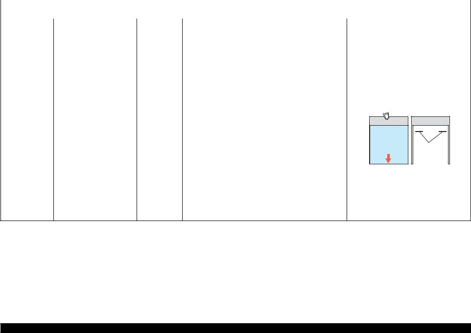
Ink Leakage during Operation 3.1.4.1 Factors which Affect the Print Quality Ink may spill when removing the following parts from L1800. This section describes the parts that may cause ink spill and the means to minimize the HOW TO PLACE THE INK TANK ASSY WHEN DISASSEMBLING/ ink spill when removing the parts.
-
Page 43
L1800 Revision A MEANS DO TO MINIMIZE THE INK SPILL DISCHARGING INK FROM THE INK SUPPLY TANK Discharging ink is recommended only when disconnecting the Ink Supply Tank Tube Even observing the points described in this section, ink may spill in C A U T I O N Assy from the Ink Supply Tank. -
Page 44
L1800 Revision A Close the choke valve, then connect the tube connected with the injector to the It is recommended that the ink in the Ink Supply Tank should C H E C K Ink Supply Tank Tube. P O I N T… -
Page 45: Protection For Transportation
L1800 Revision A 3.1.5 Protection for Transportation Securing the Ink Tank ± Prepare two pieces of strong tape (length: 90 2 mm, width: 22 mm). Before packing the printer for returning it to the user, secure it at the specified points with strong tape to avoid damaging the printer or ink leakage during transport, and Install the Ink Supply Tank Assy to the printer.
-
Page 46: Locking/Releasing The Carriage
L1800 Revision A 3.1.6 Locking/Releasing the Carriage Points to be checked before packing the printer Locking and releasing the Carriage is shown below. The Valve Lever is on the position All the caps of the Ink Supply Tank shown below (the Choke Valve is Assy are securely closed.
-
Page 47: Method For Making Adapter Guide Holder Removal Tool
L1800 Revision A 3.1.7 Method for making Adapter Guide Holder removal tool The Adapter Guide Holder (refer to p.58) can be easily removed by using a special tool. The method for making the tool is described below. Prepare a handle part of a clip, or a similar metal wire piece.
-
Page 48: Disassembly
L1800 Revision A 3.1.8 Disassembly The flowchart below lists the step-by-step disassembly procedures. When disassembling each unit, refer to the page number shown in the figure. Start The boxes shown in a dotted-line are not the shortest C H E C K P O I N T procedures, but are necessary to proceed to the next step.
-
Page 49
L1800 Revision A Lower Housing / Ink Supply Tube Ink Supply Tank Ink Supply Tank Adapter section Printer Mechanism Assy section Tube Assy section Assy section (p.101) (p.61) (p.102) (p.104) (p.105) Front Paper Guide Pad ASF Assy (p.71) PF Motor (p.95) Waste Ink Pad (p.79) -
Page 50: Removing The Housings
L1800 Revision A 3.2 Removing the Housings 3.2.2 Stacker Assy To disengage the guide pin on the right of the Stacker Assy, push the Stopper in 3.2.1 Paper Support Assy the direction of the arrow with a flathead screwdriver or similar tool.
-
Page 51: Front Decoration Plate Left/Right
L1800 Revision A 3.2.3 Front Decoration Plate Left/Right 3.2.4 Rear Housing Open the Stacker Assy. Remove the two C.B.P. M3 x 8 screws and the C.B.S. M3 x 6 screw that secure the Rear Housing. While releasing the hook on the Front Decoration Plate Left, open the plate in the direction of the arrow, and remove it.
-
Page 52: Panel Unit
L1800 Revision A 3.2.5 Panel Unit Align the positioning tabs (one each on the left/right) with the positioning holes (one each on the left/right) on the Upper Open the Printer Cover. Housing. Align the positioning tabs (three each on the left/right) with the…
-
Page 53
L1800 Revision A Disengage the nine hooks on the bottom of the Panel Unit, and remove the Panel Be careful not to get the Panel FFC caught underneath the Unit while pulling out its tab. hooks on the Panel Unit. -
Page 54: Decoration Plate Left/Right
L1800 Revision A 3.2.6 Decoration Plate Left/Right Release the three hooks on the front of the Decoration Plate Right and lift the plate a little to release the tab and the four guide pins on the upper side, then remove the Remove the Rear Housing.
-
Page 55: Upper Housing / Printer Cover
L1800 Revision A 3.2.7 Upper Housing / Printer Cover When installing the Decoration Plate L/R, first align the hooks of the Decoration Plate L/R (two each) with the ribs of the Remove the Decoration Plate Left/Right. (p.49) Lower Housing (two each on the left/right), and then align the Remove the Panel Unit.
-
Page 56
L1800 Revision A REMOVING THE PRINTER COVER Route the Panel FFC correctly as shown in Figure 3-21. Install the Upper Housing so that the Grounding Plate properly Remove the Upper Housing / Printer Cover. (p.50) protrudes through the cutout of the Upper Housing. -
Page 57: Upper Housing Support Assy
L1800 Revision A Be careful not to damage the surface in step 3 and later. After replacing the following parts, be sure to apply G-26 grease to the A D J U S T M E N T C A U T I O N R E Q U I R E D area specified for each part.
-
Page 58: Removing The Boards
L1800 Revision A 3.3 Removing the Boards Disconnect all the cables and FFCs connected on the Main Board from the near side one by one. 3.3.1 Board Assy (Main Board/Power Supply Board) Connector Connector Panel Board CN115 CR Motor Remove the Upper Housing / Printer Cover. (p.50)
-
Page 59
L1800 Revision A REMOVING THE POWER BOARD Confirm that the FFCs do not cross each other first, then connect the FFCs and the cables to the Main Board while paying attention Remove the Board Assy (Main Board/Power Supply Board). (p.53) to the edge of the Shield Plate. -
Page 60: Disassembling The Printer Mechanism
L1800 Revision A 3.4 Disassembling the Printer Mechanism Referring to Figure 3-35, correctly route the APG connector cable. 3.4.1 APG Assy Apply the acetate tape A according to the standard below. Remove the Upper Housing / Printer Cover. (p.50)
-
Page 61: Cr Scale
L1800 Revision A 3.4.2 CR Scale Align the phase of the APG Assy in the following procedure. 1.Align the delta marks of Spur Gear 16 and Combination Gear Remove the Upper Housing / Printer Cover. (p.50) 22, 28.8, 32.4.
-
Page 62
L1800 Revision A Remove the coil section of Torsion Spring 24.7 from the tab on the Left CR Shaft Turn the CR Scale 90º, and remove it from the tab on the Left CR Shaft Mounting Mounting Plate with tweezers. -
Page 63: Printhead / Adapter Guide Holder
L1800 Revision A 3.4.3 Printhead / Adapter Guide Holder Pass the CR Scale through the slot on the CR Encoder. So as not to damage the FFC, do not use any tools with the C A U T I O N sharp ends when removing the Cable Holder.
-
Page 64
L1800 Revision A Using the special tool (refer to Method for making Adapter Guide Holder removal Lift the Adapter Guide Holder and remove it. tool (p42)), disengage tab A of the Adapter Guide Holder on the right rear side of the Carriage Unit. -
Page 65
L1800 Revision A Disconnect the two Head FFCs on the back side, and remove the Printhead. Head FFC Figure 3-51. Removing the Printhead (2) Tighten the screws in the order shown in Figure 3-50 After replacing or removing the Printhead, always make the required… -
Page 66: Lower Housing / Printer Mechanism
L1800 Revision A 3.4.4 Lower Housing / Printer Mechanism 1) C.B.P. M3x10 (6±1 kgf.cm) Remove the Upper Housing Support Assy. (p.52) Remove the Adapter section. (p.101) Remove the Ink Supply Tube Assy section. (p.102) Printer Mechanism Remove the Ink Supply Tank Tube Assy section. (p.104) Remove the Ink Supply Tank Assy section.
-
Page 67
L1800 Revision A Install the Printer Mechanism to the Lower Housing as follows. Insert the Waste Ink Tube with the red line into the Ink Tube. (refer to Figure 3-53) 1. Align the two guide pins with the positioning holes as shown below. -
Page 68: Carriage Shaft / Carriage Unit
L1800 Revision A 3.4.5 Carriage Shaft / Carriage Unit Remove the two C.B.S. M3 x 6 screws that secure the Frame Support Plate (Left), and remove it. When only removing the Carriage Shaft, you do not need to C H E C K…
-
Page 69
L1800 Revision A Remove the foot of Left PG Torsion Spring from tab A, and remove the coil Place the feet of Left PG Torsion Spring and Right PG Torsion section from tab B to remove Left PG Torsion Spring from the Main Frame. -
Page 70
L1800 Revision A Remove the extension spring for the Driven Pulley Holder from the Main Frame 11. Remove the CR Drive Belt from the CR Motor Pinion Gear. and the tab on the Drive Pulley Holder with needle-nose pliers. CR Drive Belt… -
Page 71
L1800 Revision A 13. Loosen the C.B.S. (P4) M3 x 8 screw that secures the Left Parallelism Adjust 15. Lift the Carriage Shaft upwards, and remove the Carriage Shaft Spacer from the Bushing, and rotate the Bushing toward the front of the Printer Mechanism to Carriage Shaft with tweezers. -
Page 72
L1800 Revision A 17. Lift the Carriage Shaft within the hole on the Main Frame, and remove the Spacer Install the Right PG Cam so that one of these positions marked “0”, and Left PG Cam from the Carriage Shaft. -
Page 73
L1800 Revision A When performing the following procedure, take care not to scratch Set the longer end of the Carriage Shaft to the left side. C A U T I O N the Carriage Shaft. When the Carriage Shaft is removed, the Plain spring and Leaf spring that are attached to the right end of the Carriage Shaft may drop off. -
Page 74
L1800 Revision A 21. Insert the flathead screwdriver and such to the two holes of the Carriage Unit, and 22. Turn the Belt Holder Mounting Plate in the direction of the arrow, and remove it release the two tabs of the Ink Guide from the two hooks of the Carriage Unit, and from the Carriage Unit. -
Page 75
L1800 Revision A 24. Release the CR Encoder Board Holder from the three Tabs to remove it from the 25. Disconnect the Sensor FFC from the connector on the CR Encoder Board, pull out Carriage Unit. the Sensor FFC from the Carriage Unit, and remove the Carriage Unit. -
Page 76: Asf Assy
L1800 Revision A 3.4.6 ASF Assy Disconnect all the cables and the FFCs from the connectors on the Relay Board. CN1 : Relay FFC Remove the Upper Housing Support Assy. (p.52) CN2 : PE Sensor cable Remove the C.B.S. M3 x 8 screw that secures the Earth cables on the right rear …
-
Page 77
L1800 Revision A Remove the two C.B. M3 x 6 screws that secure the two Guide Roller LDs. Referring to Figure 3-83, correctly route each of the cables and 10. Gently pull the LD Roller Shaft to the rear of the printer, and remove the Guide FFCs. -
Page 78
L1800 Revision A 11. Remove the three C.B.S. (P4) M3 x 8 screws that secure the ASF Assy, and Align the guide pin and four Tabs on the ASF Assy with the remove the ASF Assy from the Printer Mechanism. -
Page 79: Ld Roller
L1800 Revision A 3.4.7 LD Roller After replacing or removing the ASF Assy, always make the required A D J U S T M E N T R E Q U I R E D adjustments referring to the following.
-
Page 80
L1800 Revision A Release the two tabs that secure the ASF Sensor Flag from the inside of the ASF While bending the LD Roller Shaft slightly, detach it from the shaft hole on the Assy, and remove the ASF Sensor Flag from the LD Roller Shaft. -
Page 81: Retard Roller Assy
L1800 Revision A 3.4.8 Retard Roller Assy Make sure to install the LD Roller with the triangular groove marked inside as shown below. When replacing the Retard Roller Assy, replace the LD Roller C H E C K P O I N T together with the Retard Roller Assy.
-
Page 82
L1800 Revision A Detach the extension spring from the tab of the Retard Roller Assy, and remove See below for installing the torsion spring of the Paper Back the Retard Roller Assy from the ASF Assy. Lever Right. Inside… -
Page 83: Front Paper Guide Pad
L1800 Revision A 3.4.9 Front Paper Guide Pad After installing the Front Paper Guide Pads, lift the Printer Mechanism, and check the following points. Remove the Printer Mechanism. (Refer to 3.4.4 Lower Housing / Printer Make sure that the tabs on the Pads are not cut midway.
-
Page 84: Waste Ink Pad
L1800 Revision A 3.4.10 Waste Ink Pad Route the Waste Ink Tube as shown below. Remove the Printer Mechanism. (Refer to 3.4.4 Lower Housing / Printer Mechanism (p.61).) Waste Ink Tubes Remove the C.B.P. 3×8 screw that secures the Waste Ink Tube.
-
Page 85: Foot
L1800 Revision A 3.4.11 Foot 3.4.12 Paper EJ Frame Assy Remove the Printer Mechanism. (Refer to 3.4.4 Lower Housing / Printer Remove the Upper Housing Support Assy. (p.52) Mechanism (p.61).) Remove the Ink Supply Tube Assy section. (p.102) Remove the six foot at the backside of the Lower Housing.
-
Page 86
L1800 Revision A When performing the following procedure, take care not to scratch Hook both rear ends of the Paper EJ Frame Assy onto the tabs C A U T I O N the Star Wheel. on the Main Frame. -
Page 87: Ink System Unit
L1800 Revision A 3.4.13 Ink System Unit Remove the two C.B.S. M3 x 4 screws that secure the Ink System Guide Plate, and remove it. Remove the ASF Assy. (p.71) Remove the Paper EJ Frame Assy. (p.80) Remove the Lower Housing / Printer Mechanism. (p.61) Acetate tape Release the Carriage Lock, and move the Carriage Unit to the center.
-
Page 88
L1800 Revision A Remove the two C.B.S. M3 x 6 screws that secure the Ink System Unit. 10. Remove the two C.B.S. 3×6 screws that secure the Right Support Frame, and remove the Right Support Frame from the Main Frame. -
Page 89
L1800 Revision A 11. Remove the Ink System Unit downwards from the Main Frame. Align the positioning two holes on the Main Frame with the two guide pins on the Ink System Unit. Ink System Unit Main Frame Positioning holes Figure 3-115. -
Page 90: Front Paper Guide / Paper Ej Roller
L1800 Revision A 3.4.14 Front Paper Guide / Paper EJ Roller Remove the Spacer from the EJ Roller Shaft. Remove the guide pins on Left Bushing 8 from the Main Frame using tweezers, Remove the Paper EJ Frame Assy. (p.80) and turn Left Bushing 8 toward you to align with the notches on the Main Frame.
-
Page 91
L1800 Revision A Return the Carriage Unit to its home position. 11. Pull out the Shaft of the Left Front Frame from the bushing of the Front Paper Guide and remove the Left Front Frame. Remove the C.B.S. M3 x 6 screw that secure the Left Front Frame. -
Page 92
L1800 Revision A Align the positioning holes on the Main Frame with the guide After replacing the following parts, be sure to apply G-45 grease to the A D J U S T M E N T R E Q U I R E D pins on the Front Paper Guide. -
Page 93: Pf Roller Shaft
L1800 Revision A 3.4.15 PF Roller Shaft Remove the PG Grounding Spring from the notch on the Main Frame, and remove the PF Grounding Spring from the groove on the PF Roller Shaft. Remove the Front Paper Guide / Paper EJ Roller. (p.85) Remove the PF Encoder.
-
Page 94
L1800 Revision A Remove the guide pin of Left Bushing 8 from the Main Frame using tweezers, and When performing the following procedure, pay attention to the C A U T I O N rotate the Bushing upwards to align with the notch on the Main Frame. -
Page 95: Release Holder Assy
L1800 Revision A 3.4.16 Release Holder Assy Be careful not to move Compression Spring 4 and the Leaf Spring C A U T I O N on the left side of the PF Roller Shaft to the coated section on the Remove the Lower Housing / Printer Mechanism.
-
Page 96: Upper Paper Guide Assys
L1800 Revision A 3.4.17 Upper Paper Guide Assys Align the three upper tabs on the Release Holder Assy with the positioning holes on the Main Frame. See Figure 3-134 (p.90) Remove the Release Holder Assy. (p.90) Tighten the screws in the order shown in Figure 3-134 Remove the PE Sensor Holder.
-
Page 97
L1800 Revision A Remove the six Upper Paper Guide Torsion Springs from the tabs on the Main Make sure that the leading end of the Upper Paper Guide Torsion Frame, and pull out the Upper Paper Guide Torsion Springs from the six Upper Spring can be seen through the hole of the Upper Paper Guide Assy. -
Page 98: Removing The Motors
L1800 Revision A 3.5 Removing the Motors Attach two pieces of acetate tape (18 mm) on the Upper Shield Plate. 3.5.1 CR Motor Acetate tape (18mm) Remove the ASF Assy. (p.71) Acetate tape (18mm) Release the Carriage Lock, and move the Carriage Unit to the center.
-
Page 99
L1800 Revision A .Press the Driven Pulley toward the center to loosen the CR Drive Belt, and Make the Lot No. printed surface on the CR Motor face the remove the CR Drive Belt from the CR Motor Pinion Gear. -
Page 100: Pf Motor
L1800 Revision A 3.5.2 PF Motor Make the slit on the PF Motor face the direction shown in the A D J U S T M E N T R E Q U I R E D figure below.
-
Page 101: Asf Motor
L1800 Revision A 3.5.3 ASF Motor Attach a piece of acetate tape (60 mm) on the ASF Motor Cable as shown below. Remove the Upper Housing / Printer Cover. (p.50) Remove the Earth cable. (refer to 3.4.6 ASF Assy Step2 (p71) .)
-
Page 102: Removing The Sensors
L1800 Revision A 3.6 Removing the Sensors 3.6.2 PF Encoder Remove the Upper Housing / Printer Cover. (p.50) 3.6.1 CR Encoder Disconnect the FFC from the PF Encoder Sensor Board. Remove the Carriage Shaft / Carriage Unit. (p.63) Remove the C.B.S. M3 x 8 screw that secures the PF Encoder Sensor Holder.
-
Page 103: Pw Sensor
L1800 Revision A 3.6.3 PW Sensor While pressing the guide pin on the PF Encoder Sensor Holder using tweezers, slide the holder upwards to release the three tabs, and remove the PF Encoder Remove the Carriage Shaft / Carriage Unit. (p.63) Sensor Holder.
-
Page 104: Pe Sensor Holder
L1800 Revision A 3.6.4 PE Sensor Holder Make sure that the PW Sensor FFC is routed as shown in Figure 3-154 Remove the Lower Housing / Printer Mechanism. (p.61) Remove the ASF Assy. (p.71) Remove the PE Sensor connector cable from the five tabs on the Release Holder Assy and the two tabs on the Head Cable Cover.
-
Page 105
L1800 Revision A Align the four tabs and guide pin on the PE Sensor Holder with the positioning holes on the Main Frame correctly so that there is no gap between the PE Sensor Holder and the Main Frame. Tabs… -
Page 106: Disassembling The Ciss Section
L1800 Revision A 3.7 Disassembling the CISS section 3.7.1.2 Adapter 3.7.1 Adapter section Hook Adapter 3.7.1.1 Adapter Cover Film Timing Belt Carriage Unit Connection of Ink Supply Tubes Ink Supply Tube Assy Adapter Cover Dowel and Hole Hook Adapter Ink Supply Tube CBP.
-
Page 107: Ink Supply Tube Assy Section
L1800 Revision A 3.7.2 Ink Supply Tube Assy section 3.7.2.2 Tube Guide Sheet (w/Tube Guide Sheet sub) 3.7.2.1 Tube Guide Sheet/Tube Guide Sheet Sub Step 1 Carriage Unit Tube Guide Sheet Hole 1 Hole 2 Tube Guide Sheet Sub Section A…
-
Page 108: Ink Supply Tube Assy
L1800 Revision A 3.7.2.3 Ink Supply Tube Assy Ink Supply Tube Assy Ink Supply Tube Assy Carriage Unit Joint Ink Supply Tube Adapter Assy side Joint side 352.5 ± 1 95 ± 1 67.5 ± 1 Yellow Black Light Cyan…
-
Page 109: Ink Supply Tank Tube Assy Section
L1800 Revision A 3.7.3 Ink Supply Tank Tube Assy section 3.7.3.1 Ink Supply Tank Tube Assy Valve Case Tube Clamp Joint Arch Bottom Tube Holder 179 ± 1 mm 278 ± 1 mm Hole Yellow 453 ± 3 mm Black 424 ±…
-
Page 110: Joint
L1800 Revision A 3.7.4 Ink Supply Tank Assy section 3.7.3.2 Joint 3.7.4.1 Valve Position Label Ink Supply Tube Joint Cutout 0.5 mm or less Joint Valve Position Label 7.5 mm 7.5 mm 0.5 mm or less Ink Supply Tank Tube…
-
Page 111: Top Cover
L1800 Revision A 3.7.4.2 Top Cover 3.7.4.3 Tube Valve Holder Front/Rear Refilling Ink Label Ink Supply Tank Tube Refilling Ink Label 13 ± 1 mm Tube Valve Holder Rear Valve Case 6 ± 1 mm Tube Valve Holder Front Tube Valve Holder Rear…
-
Page 112: Valve Lever
L1800 Revision A 3.7.4.4 Valve Lever 3.7.4.5 Ink Supply Tank Assy Ink Supply Tank Tube Valve Holder Rear Ink Supply Tank Assy Flathead precision screwdriver Film Valve Lever Right Cover Hook Follow the procedure below when removing the Valve Lever.
-
Page 113: Bottom Cover/Left Cover/Right Cover/Cover Joint
L1800 Revision A 3.7.4.6 Bottom Cover/Left Cover/Right Cover/Cover Joint Left Cover Cover Joint Ink Supply Tank Assy Right Cover Bottom Cover Hook C.B.P. 3X6 (4±1 kgf.cm) Be careful about how to place the Ink Supply Tank Assy in order to prevent printing failure from occurring. (See “How to place the Ink Tank Assy when disassembling/reassembling”…
-
Page 114
C H A P T E R ADJUSTMENT Confidential… -
Page 115: Adjustment Items And Overview
L1800 Revision A 4.1 Adjustment Items and Overview This chapter describes adjustments to be made after the disassembly/reassembly of this product. 4.1.1 Servicing Adjustment Item List The items, purposes and outlines of the Adjustment Program are given in the following table.
-
Page 116
L1800 Revision A Table 4-1. Adjustment Items Adjustment Purpose Method Outline Initialize PF The deterioration amount of the PF Roller Shaft is reflected to 1. Select and execute this function in the Adjustment Program. deterioration offset the paper feed correction amount. Every time a sheet of paper is 2. -
Page 117
L1800 Revision A Table 4-1. Adjustment Items Adjustment Purpose Method Outline CR motor heat protection When replacing the Printer Mechanism, this adjustment is made 1. Select this function in the Adjustment Program. control to measure the load of Carriage sliding, and manufacturing 2. -
Page 118
L1800 Revision A Table 4-3. Additional Functions Function Item Purpose Method Outline Final check pattern print A4 size Use this to check if the all adjustments have been properly The all adjustment patterns are printed automatically. made. US Letter size EEPROM dump Use this to read out the EEPROM data for analysis. -
Page 119: Required Adjustments
L1800 Revision A 4.1.2 Required Adjustments The table below lists the required adjustments depending upon the parts being repaired or replaced. Find the part(s) you removed or replaced, and check which adjustment(s) must be carried out. Table 4-4. Required Adjustment List…
-
Page 120
L1800 Revision A Table 4-4. Required Adjustment List Priority Adjustment Item Part Name Waste Ink Pad/ Remove Front Paper Guide Replace Remove Carriage shaft Replace Remove Carriage Unit Replace Remove Paper EJ Frame Assy Replace Remove Printer Mechanism Replace Remove… -
Page 121: Required Adjustment Tools
L1800 Revision A 4.1.3 Required Adjustment Tools Table 4-5. List of Tools Name Part Code Category Overview The following table lists the adjustment tools required for adjustment of this product. Level Block Used to check whether or not 1304994 Adjusting Table 4-5.
-
Page 122: Adjustment Using Adjustment Program
L1800 Revision A 4.2 Adjustment Using Adjustment Program Additional information In the following cases, reassemble or replace the Printhead and carry out the This section explains the adjustments using the Adjustment Program. adjustment again. 4.2.1 Head angular adjustment The difference between the adjusted values of 1 -> 80 and 80 -> 1 exceeds 8.
-
Page 123: Pw Adjustment/First Dot Position Adjustment
L1800 Revision A 4.2.2 PW Adjustment/First Dot Position Adjustment PW Adjustment How to Judge Patterns are printed as shown below. Enter the value of the line located 5mm away from each edge. Example: In the left figure, enter “0” (top), “5” (bottom), “-3” (left) and “0” (right).
-
Page 124: Bi-D Adjustment
L1800 Revision A 4.2.3 Bi-D adjustment The pattern shown below is printed for each of the PG settings. Figure 4-3. Bi-D Adjustment Printout Pattern How to Judge Examine the printout patterns for each of the five modes, and enter the value for the pattern with no gap and overlap for each mode.
-
Page 125: Band Printing Adjustment
L1800 Revision A 4.2.4 BAND printing adjustment Bi-d band adjustment How to Judge The following pattern is printed on two sheets each for Bi-d band adjustment and Pass offset adjustment with two dot sizes (ECO, VSD1). Examine the printout patterns and enter the values of the most straight lines.
-
Page 126: Pf Adjustment
L1800 Revision A 4.2.5 PF adjustment PF- for bottom margin area The following pattern is printed. PF- for standard print area How to Judge The following pattern is printed. Examine the printout patterns, and enter the value for the pattern with no overlap and gap between the upper and lower ones.
-
Page 127: Pf Band Adjustment
L1800 Revision A 4.2.6 PF band adjustment 4.3 Adjustment without Using Adjustment Program The following pattern is printed. This section explains the adjustments that do not use the Adjustment Program. 4.3.1 PF Belt Tension Adjustment When either of the following parts has been removed or replaced, this adjustment must be performed to reduce load on the PF Motor and to secure paper feed accuracy.
-
Page 128: Pf Belt Tension Adjustment Method
L1800 Revision A 4.3.1.1 PF Belt Tension Adjustment Method As the Drive Belt is flipped with the tip of tweezers in the following C A U T I O N steps, carefully choose the flipping position so that the Belt will not…
-
Page 129: Pg Adjustment
C H E C K around the Print Head. Remaining drops of ink will stick to the adjustment method for L1800 is the same as the one for Stylus P O I N T continuity measurement portion of the Adjustment Gauge, and Photo R1800.
-
Page 130
L1800 Revision A Load Adapter of all colors into the Carriage Unit. With its conductor connection portion up, set the Adjustment Gauge in the specified position (on the left side of the Front Paper Guide). Loosen the screw that secures the Parallelism Adjust Bushing. -
Page 131
L1800 Revision A To set the PG position to the “—” position, turn the PG Cam on the right end of the The following figure shows the states of the Adjust Parallel Bushing C H E C K Carriage Shaft clockwise so that the point marked “—” faces down. -
Page 132: Pf Roller Shaft Center Support Position Adjustment
L1800 Revision A 4.3.3 PF Roller Shaft Center Support Position 12. Move the Carriage Unit onto the Adjustment Gauge. Moving position Adjustment Align the right end of the Gauge with the right end of the Carriage Unit. This adjustment must be performed to compensate the deflection amount on the PF Roller Shaft and to maintain an appropriate paper feed amount when the following parts are removed and replaced.
-
Page 133: How To Adjust The Pf Roller Shaft Center Support Position
L1800 Revision A 4.3.4 How to Adjust the PF Roller Shaft Center Tilt the Printer Mechanism at about 45 degrees, and loosen the screws that secure the Center Support Bushing Cam and the Center Support Bush. Support Position Before performing this adjustment, remove the following parts: Bottom of Rear Center …
-
Page 134
L1800 Revision A Turn the Center Support Bushing Cam so that the long hand position is +30 from Check for any dirt on the PF Roller Shaft when performing the C A U T I O N the “0” adjustment position. -
Page 135
L1800 Revision A Unevenness Figure 4-24. Outside the Specified Value Range Figure 4-25. Inside the Specified Value Range Adjustment Adjustment without Using Adjustment Program Confidential… -
Page 136: Asf Guide Roller Lds Position Adjustment
L1800 Revision A 4.3.5 ASF Guide Roller LDs Position Adjustment Turn Combination Gear 29.11 on the right side of the ASF Assy CCW to raise the Hopper to the upper limit position (until the Hopper Pad contacts the LD Roller).
-
Page 137
L1800 Revision A Light the printer’s inside through a gap between the Roll Paper Frame and the ASF Align the guide pin and tab on the 0 Digit Side Guide Roller LD with the Assy with a penlight, and look the tab on the Retard Roller Holder at the back of positioning holes on the Main Frame, and tighten the Guide Roller LD (0 Digit the two reference tabs on the ASF Assy through the notch. -
Page 138
C H A P T E R MAINTENANCE Confidential… -
Page 139: Overview
L1800 Revision A 5.1 Overview 5.1.2 Service Maintenance If print irregularity (missing dot, white line, etc.) has occurred or the printer indicates This section provides information to maintain the printer in its optimum condition. “Maintenance Error”, take the following actions to clear the error.
-
Page 140: Maintenance Request
L1800 Revision A 5.1.2.2 Maintenance Request Waste Ink Pads to be replaced When the ink is used for the Print Head cleaning and such, it is drained via the Cap Table 5-1. List of Waste Ink Pads to be replaced Unit to the Waste Ink Pad located on the Lower Housing.
-
Page 141: Lubrication
The lubrication used for the components of the printer has been decided on based on Bushings (outer circumference) evaluation carried out by Epson. Therefore, the specified amount and places of <Lubrication Type> lubrication given in this section should be strictly observed.
-
Page 142
L1800 Revision A <Lubrication Point> <Lubrication Point> Right PG Torsion Spring Contact point of the Main Frame and Contact point of the Left and Right PG the CR the Scale Mounting Plate Torsion Springs and the Carriage (Left/Right) Shaft. <Lubrication Type>… -
Page 143
L1800 Revision A <Lubrication Point> <Lubrication Point> Right Side The Driven Pulley Holder The bushing of the Front Paper Guide Front Paper Guide <Lubrication Type> <Lubrication Type> G-26 G-45 <Lubrication Amount> <Lubrication Amount> 1mm x 2mm x 4 points 1. -
Page 144
L1800 Revision A <Lubrication Point> <Lubrication Point> Upper surface Lower surface PF Grounding Spring Rear Paper Guide 1. Contact point of the Rear Paper Contact point of the Printer Cover Guide and the PF Roller Holder (Left/Right) and the Printer Cover 2. -
Page 145
L1800 Revision A <Lubrication Point> <Lubrication Point> Right Side Left Side Contact point of the Shaft of the ASF Contact point of the Housing Upper Shaft of the ASF Frame Frame and the Combination Gear and the Printer Cover 29.11 <Lubrication Type>… -
Page 146: Lubrication Of Carriage Shaft
L1800 Revision A 5.1.3.1 Lubrication of Carriage Shaft Hold the Carriage Unit, and while turning the Carriage Shaft clockwise and counterclockwise, move the Carriage Unit to spread the grease evenly. Fit the Carriage Unit onto the Carriage Shaft, and move it to the center of the Shaft.
-
Page 147
L1800 Revision A Hold the Carriage Unit, and while turning the Carriage Shaft, move the Carriage Hold the Carriage Unit, and while turning the Carriage Shaft, move the Carriage Unit to the left end of the Carriage Shaft to lubricate the grease evenly. -
Page 148
C H A P T E R APPENDIX Confidential… -
Page 149: Connector Summary
L1800 Revision A 6.1 Connector Summary This section shows the connections between the main components of the printer. CA86 PSB (Power Supply Board) Control Panel CA53MAIN (CD81 Panel Board) (Main Board) Table 6-1. Connection of the Major Components Appendix Connector Summary…
![]()
SERVICE MANUAL
Color Inkjet Printer
L1800
Confidential
SEIJ13-007
Notice:
All rights reserved. No part of this manual may be reproduced, stored in a retrieval system, or transmitted in any form or by any means, electronic, mechanical, photocopying, recording, or otherwise, without the prior written permission of SEIKO EPSON CORPORATION.
The contents of this manual are subject to change without notice.
All effort have been made to ensure the accuracy of the contents of this manual. However, should any errors be detected, SEIKO EPSON would greatly appreciate being informed of them.
The above not withstanding SEIKO EPSON CORPORATION can assume no responsibility for any errors in this manual or the consequences thereof.
EPSON is a registered trademark of SEIKO EPSON CORPORATION.
|
General Notice: |
Other product names used herein are for identification purpose only and may be trademarks or registered trademarks of their |
|
respective owners. EPSON disclaims any and all rights in those marks. |
Copyright © 2014 SEIKO EPSON CORPORATION.
Printer CS Quality Assurance Department
Confidential
PRECAUTIONS
Precautionary notations throughout the text are categorized relative to 1)Personal injury and 2) damage to equipment.
|
DANGER |
Signals a precaution which, if ignored, could result in serious or fatal personal injury. Great caution should be exercised in performing procedures preceded by |
|
DANGER Headings. |
|
|
WARNING |
Signals a precaution which, if ignored, could result in damage to equipment. |
The precautionary measures itemized below should always be observed when performing repair/maintenance procedures.
DANGER
1.ALWAYS DISCONNECT THE PRODUCT FROM THE POWER SOURCE AND PERIPHERAL DEVICES PERFORMING ANY MAINTENANCE OR REPAIR PROCEDURES.
2.NO WORK SHOULD BE PERFORMED ON THE UNIT BY PERSONS UNFAMILIAR WITH BASIC SAFETY MEASURES AS DICTATED FOR ALL ELECTRONICS TECHNICIANS IN THEIR LINE OF WORK.
3.WHEN PERFORMING TESTING AS DICTATED WITHIN THIS MANUAL, DO NOT CONNECT THE UNIT TO A POWER SOURCE UNTIL INSTRUCTED TO DO SO. WHEN THE POWER SUPPLY CABLE MUST BE CONNECTED, USE EXTREME CAUTION IN WORKING ON POWER SUPPLY AND OTHER ELECTRONIC COMPONENTS.
4.WHEN DISASSEMBLING OR ASSEMBLING A PRODUCT, MAKE SURE TO WEAR GLOVES TO AVOID INJURIER FROM METAL PARTS WITH SHARP EDGES.
WARNING
1.REPAIRS ON EPSON PRODUCT SHOULD BE PERFORMED ONLY BY AN EPSON CERTIFIED REPAIR TECHNICIAN.
2.MAKE CERTAIN THAT THE SOURCE VOLTAGES IS THE SAME AS THE RATED VOLTAGE, LISTED ON THE SERIAL NUMBER/RATING PLATE. IF THE EPSON PRODUCT HAS A PRIMARY AC RATING DIFFERENT FROM AVAILABLE POWER SOURCE, DO NOT CONNECT IT TO THE POWER SOURCE.
3.ALWAYS VERIFY THAT THE EPSON PRODUCT HAS BEEN DISCONNECTED FROM THE POWER SOURCE BEFORE REMOVING OR REPLACING PRINTED CIRCUIT BOARDS AND/OR INDIVIDUAL CHIPS.
4.IN ORDER TO PROTECT SENSITIVE MICROPROCESSORS AND CIRCUITRY, USE STATIC DISCHARGE EQUIPMENT, SUCH AS ANTI-STATIC WRIST STRAPS, WHEN ACCESSING INTERNAL COMPONENTS.
5.REPLACE MALFUNCTIONING COMPONENTS ONLY WITH THOSE COMPONENTS BY THE MANUFACTURE; INTRODUCTION OF SECOND-SOURCE ICs OR OTHER NON-APPROVED COMPONENTS MAY DAMAGE THE PRODUCT AND VOID ANY APPLICABLE EPSON WARRANTY.
6.WHEN USING COMPRESSED AIR PRODUCTS; SUCH AS AIR DUSTER, FOR CLEANING DURING REPAIR AND MAINTENANCE, THE USE OF SUCH PRODUCTS CONTAINING FLAMMABLE GAS IS PROHIBITED.
Confidential

About This Manual
This manual describes basic functions, theory of electrical and mechanical operations, maintenance and repair procedures of the printer. The instructions and procedures included herein are intended for the experienced repair technicians, and attention should be given to the precautions on the preceding page.
Manual Configuration
This manual consists of six chapters and Appendix.
CHAPTER 1.PRODUCT DESCRIPTIONS
Provides a general overview and specifications of the product.
CHAPTER 2.TROUBLESHOOTING
Describes the step-by-step procedures for the troubleshooting.
CHAPTER 3.DISASSEMBLY / ASSEMBLY
Describes the step-by-step procedures for disassembling and assembling the product.
CHAPTER 4.ADJUSTMENT
Provides Epson-approved methods for adjustment.
CHAPTER 5.MAINTENANCE
Provides preventive maintenance procedures and the lists of Epsonapproved lubricants and adhesives required for servicing the product.
APPENDIX Provides the following additional information for reference:
• Connector Summary
Symbols Used in this Manual
Various symbols are used throughout this manual either to provide additional information on a specific topic or to warn of possible danger present during a procedure or an action. Be aware of all symbols when they are used, and always read NOTE, CAUTION, or WARNING messages.
Indicates an operating or maintenance procedure, practice or condition that is necessary to keep the product’s quality.
Indicates an operating or maintenance procedure, practice, or condition that, if not strictly observed, could result in damage to, or destruction of, equipment.
May indicate an operating or maintenance procedure, practice or condition that is necessary to accomplish a task efficiently. It may also provide additional information that is related to a specific subject, or comment on the results achieved through a previous action.
Indicates an operating or maintenance procedure, practice or condition that, if not strictly observed, could result in injury or loss of life.
Indicates that a particular task must be carried out according to a certain standard after disassembly and before re-assembly, otherwise the quality of the components in question may be adversely affected.
Confidential

|
Revision Status |
||
|
Revision |
Date of Issue |
Description |
|
A |
February 10, 2014 |
First Release |
Confidential

|
Chapter 1 Product Description |
|
|
1.1 Operation Buttons & Indicators (LEDs)………………………………………………………. |
4 |
|
1.1.1 Operation Buttons ……………………………………………………………………………. |
4 |
|
1.1.2 Indicators (LEDs) ……………………………………………………………………………. |
4 |
|
1.1.3 Operation Buttons & LEDs Functions ……………………………………………….. |
4 |
|
1.1.4 Errors & Remedies ………………………………………………………………………….. |
6 |
|
Chapter 2 Troubleshooting |
|
|
2.1 Overview ………………………………………………………………………………………………… |
8 |
|
2.1.1 Troubleshooting according to Error Messages …………………………………….. |
8 |
|
2.1.2 Troubleshooting based on Observed Faults ………………………………………. |
24 |
|
Chapter 3 Disassembly And Assembly |
|
|
3.1 Overview ………………………………………………………………………………………………. |
35 |
|
3.1.1 Precautions …………………………………………………………………………………… |
35 |
|
3.1.2 Tools ……………………………………………………………………………………………. |
36 |
|
3.1.3 Screws ………………………………………………………………………………………….. |
36 |
|
3.1.4 Checks and Precautions before Disassembling ………………………………….. |
37 |
|
3.1.4.1 Factors which Affect the Print Quality ………………………………………. |
37 |
|
3.1.4.2 Factors which Affect the Safety of Service Personnel such as |
|
|
Ink Leakage during Operation ………………………………………………….. |
37 |
|
3.1.5 Protection for Transportation ………………………………………………………….. |
40 |
|
3.1.6 Locking/Releasing the Carriage ………………………………………………………. |
41 |
|
3.1.7 Method for making Adapter Guide Holder removal tool …………………….. |
42 |
|
3.1.8 Disassembly ………………………………………………………………………………….. |
43 |
|
3.2 Removing the Housings ………………………………………………………………………….. |
45 |
|
3.2.1 Paper Support Assy ……………………………………………………………………….. |
45 |
|
3.2.2 Stacker Assy …………………………………………………………………………………. |
45 |
|
3.2.3 Front Decoration Plate Left/Right ……………………………………………………. |
46 |
|
3.2.4 Rear Housing ………………………………………………………………………………… |
46 |
|
3.2.5 Panel Unit …………………………………………………………………………………….. |
47 |
|
3.2.6 Decoration Plate Left/Right …………………………………………………………….. |
49 |
|
3.2.7 Upper Housing / Printer Cover ………………………………………………………… |
50 |
|
3.2.8 Upper Housing Support Assy ………………………………………………………….. |
52 |
|
3.3 Removing the Boards ……………………………………………………………………………… |
53 |
|
3.3.1 Board Assy (Main Board/Power Supply Board) ………………………………… |
53 |
|
3.4 Disassembling the Printer Mechanism ………………………………………………………. |
55 |
|
3.4.1 APG Assy …………………………………………………………………………………….. |
55 |
|
3.4.2 CR Scale ………………………………………………………………………………………. |
56 |
|
3.4.3 Printhead / Adapter Guide Holder ……………………………………………………. |
58 |
|
3.4.4 Lower Housing / Printer Mechanism ……………………………………………….. |
61 |
|
3.4.5 Carriage Shaft / Carriage Unit …………………………………………………………. |
63 |
|
3.4.6 ASF Assy ……………………………………………………………………………………… |
71 |
|
3.4.7 LD Roller ……………………………………………………………………………………… |
74 |
|
3.4.8 Retard Roller Assy ………………………………………………………………………… |
76 |
|
3.4.9 Front Paper Guide Pad …………………………………………………………………… |
78 |
|
3.4.10 Waste Ink Pad ……………………………………………………………………………… |
79 |
|
3.4.11 Foot ……………………………………………………………………………………………. |
80 |
|
3.4.12 Paper EJ Frame Assy ……………………………………………………………………. |
80 |
|
3.4.13 Ink System Unit …………………………………………………………………………… |
82 |
|
3.4.14 Front Paper Guide / Paper EJ Roller ………………………………………………. |
85 |
|
3.4.15 PF Roller Shaft ……………………………………………………………………………. |
88 |
|
3.4.16 Release Holder Assy ……………………………………………………………………. |
90 |
|
3.4.17 Upper Paper Guide Assys ……………………………………………………………… |
91 |
|
3.5 Removing the Motors……………………………………………………………………………… |
93 |
|
3.5.1 CR Motor ……………………………………………………………………………………… |
93 |
|
3.5.2 PF Motor ………………………………………………………………………………………. |
95 |
|
3.5.3 ASF Motor ……………………………………………………………………………………. |
96 |
|
3.6 Removing the Sensors …………………………………………………………………………….. |
97 |
|
3.6.1 CR Encoder ………………………………………………………………………………….. |
97 |
|
3.6.2 PF Encoder …………………………………………………………………………………… |
97 |
|
3.6.3 PW Sensor ……………………………………………………………………………………. |
98 |
|
3.6.4 PE Sensor Holder ………………………………………………………………………….. |
99 |
|
3.7 Disassembling the CISS section……………………………………………………………… |
101 |
|
3.7.1 Adapter section ……………………………………………………………………………. |
101 |
|
3.7.1.1 Adapter Cover ……………………………………………………………………… |
101 |
1
Confidential

|
3.7.1.2 Adapter ……………………………………………………………………………….. |
101 |
|
3.7.2 Ink Supply Tube Assy section ……………………………………………………….. |
102 |
|
3.7.2.1 Tube Guide Sheet/Tube Guide Sheet Sub ………………………………… |
102 |
|
3.7.2.2 Tube Guide Sheet (w/Tube Guide Sheet sub) …………………………… |
102 |
|
3.7.2.3 Ink Supply Tube Assy …………………………………………………………… |
103 |
|
3.7.3 Ink Supply Tank Tube Assy section ……………………………………………….. |
104 |
|
3.7.3.1 Ink Supply Tank Tube Assy …………………………………………………… |
104 |
|
3.7.3.2 Joint ……………………………………………………………………………………. |
105 |
|
3.7.4 Ink Supply Tank Assy section ……………………………………………………….. |
105 |
|
3.7.4.1 Valve Position Label …………………………………………………………….. |
105 |
|
3.7.4.2 Top Cover ……………………………………………………………………………. |
106 |
|
3.7.4.3 Tube Valve Holder Front/Rear ……………………………………………….. |
106 |
|
3.7.4.4 Valve Lever …………………………………………………………………………. |
107 |
|
3.7.4.5 Ink Supply Tank Assy …………………………………………………………… |
107 |
|
3.7.4.6 Bottom Cover/Left Cover/Right Cover/Cover Joint ………………….. |
108 |
|
Chapter 4 Adjustment |
|
|
4.1 Adjustment Items and Overview …………………………………………………………….. |
110 |
|
4.1.1 Servicing Adjustment Item List ……………………………………………………… |
110 |
|
4.1.2 Required Adjustments ………………………………………………………………….. |
114 |
|
4.1.3 Required Adjustment Tools …………………………………………………………… |
116 |
|
4.2 Adjustment Using Adjustment Program ………………………………………………….. |
117 |
|
4.2.1 Head angular adjustment ………………………………………………………………. |
117 |
|
4.2.2 PW Adjustment/First Dot Position Adjustment ……………………………….. |
118 |
|
4.2.3 Bi-D adjustment …………………………………………………………………………… |
119 |
|
4.2.4 BAND printing adjustment ……………………………………………………………. |
120 |
|
4.2.5 PF adjustment ……………………………………………………………………………… |
121 |
|
4.2.6 PF band adjustment ……………………………………………………………………… |
122 |
|
4.3 Adjustment without Using Adjustment Program ………………………………………. |
122 |
|
4.3.1 PF Belt Tension Adjustment …………………………………………………………. |
122 |
|
4.3.1.1 PF Belt Tension Adjustment Method ………………………………………. |
123 |
|
4.3.2 PG Adjustment ……………………………………………………………………………. |
124 |
|
4.3.2.1 PG Adjustment Method …………………………………………………………. |
124 |
|
4.3.3 PF Roller Shaft Center Support Position Adjustment ……………………….. |
127 |
|
4.3.4 How to Adjust the PF Roller Shaft Center |
|
|
Support Position ………………………………………………………………………………….. |
128 |
|
4.3.5 ASF Guide Roller LDs Position Adjustment …………………………………… |
131 |
|
4.3.5.1 Adjusting the Position of the ASF Guide Roller LDs ………………… |
131 |
|
Chapter 5 Maintenance |
|
|
5.1 Overview …………………………………………………………………………………………….. |
134 |
|
5.1.1 Cleaning ……………………………………………………………………………………… |
134 |
|
5.1.2 Service Maintenance ……………………………………………………………………. |
134 |
|
5.1.2.1 Head Cleaning ……………………………………………………………………… |
134 |
|
5.1.2.2 Maintenance Request ……………………………………………………………. |
135 |
|
5.1.3 Lubrication …………………………………………………………………………………. |
136 |
|
5.1.3.1 Lubrication of Carriage Shaft …………………………………………………. |
141 |
|
Chapter 6 Appendix |
|
|
6.1 Connector Summary……………………………………………………………………………… |
144 |
2
Confidential

C H A P T E R
1
PRODUCT DESCRIPTION
Confidential
1.1 Operation Buttons & Indicators (LEDs)
1.1.1 Operation Buttons
The printer has the following four operation buttons.
|
Table 1-1. Operation Buttons |
||
|
Button |
Function |
|
|
Power |
Turn the power of this unit on/off. |
|
|
Paper |
In motion:Release error |
|
|
In Idle: Load and Eject paper |
||
|
Ink |
Start Initial Ink Charge or Head cleaning. |
|
|
Cancel |
In motion:Cancels the job execution / Release error |
|
1.1.2 Indicators (LEDs)
Three indicators (LEDs) are provided to indicate settings or printer status.
Table 1-2. Indicators (LEDs)
|
LED |
Function |
|
|
Power LED (green) |
Indicates power on/off. |
|
|
Paper LED (red) |
Indicates paper error. |
|
|
Ink LED (red) |
Light when the maintenance error occurring. |
|
|
Power LED |
Paper LED |
Ink LED |
|
Power Button |
Paper |
Button |
Ink |
Button Cancel |
Button |
||||||||
Figure 1-1. Buttons & LEDs
1.1.3 Operation Buttons & LEDs Functions
Detailed information on the buttons and LEDs functions are listed below.
Table 1-3. Operation Button Functions
|
Button |
Printer |
Function |
||
|
Status |
||||
|
Power |
Off |
Turns the power on. |
||
|
On |
Turns the power off. |
|||
|
When the condition is Idle, Loads and Ejects the |
||||
|
paper. |
||||
|
When the following condition, loads the paper by |
||||
|
pressing this key. Release the error display and |
||||
|
continue the procedure if the paper loading is |
||||
|
success. |
||||
|
Paper |
On |
• |
Paper Out Error |
|
|
• |
Multiple Feed Error |
|||
|
• Ink waste pad near end error |
||||
|
When the following condition, ejects the paper by |
||||
|
pressing this key. Release the error display and |
||||
|
continue the procedure if the paper ejecting is |
||||
|
success. |
||||
|
• |
Paper jam error |
|||
|
Ink |
Runs a head cleaning. |
|||
|
(Press 3 seconds or |
On |
|||
|
Runs a Initial Ink Charge. |
||||
|
more) |
||||
|
Cancel |
On |
Stop printing, and cancel the job of print. |
||
|
When the error occurs, it cancels error release & |
||||
|
stops printing and ejects the paper if it exists. |
||||
|
Print nozzle check pattern after normal Initializing |
||||
|
Paper + Power |
On |
procedure is done. |
||
|
If initial ink fill is not done, execute only initial ink |
||||
|
fill. Printer does not print nozzle check pattern. |
|
Product Description |
Operation Buttons & Indicators (LEDs) |
4 |
Confidential

|
L1800 |
Revision A |
|||||
|
Table 1-4. Indicators (LEDs) Function |
Note : |
—:No change |
||||
|
Flash: Repeats turning On and Off every 1.25 seconds. |
||||||
|
Indicators (LEDs) |
||||||
|
Printer Status |
Priority*1 |
Flash at high speed: Repeats turning On and Off every 0.5 seconds. |
||||
|
Power |
Paper |
Ink |
||||
|
Flashes alternately 1:Same as the “Flash” |
||||||
|
Flashes alternately 2:Repeats turning Off and On every 1.25 seconds. |
||||||
|
Power off (shutting down) |
Flashes at |
— |
— |
1 |
||
|
high speed |
||||||
|
Firmware update (While preparing) |
— |
— |
— |
2 |
||
|
Firmware update (Starting) |
Flashes |
OFF |
OFF |
|||
|
Fatal error |
OFF |
Flashes at |
Flashes at |
3 |
||
|
high speed |
high speed |
|||||
|
Ink waste pad overflow error |
— |
Flashes |
Flashes |
4 |
||
|
alternately 1 |
alternately 2 |
|||||
|
Ink waste pad near end error |
— |
Flashes |
Flashes |
5 |
||
|
alternately 1 |
alternately 2 |
|||||
|
Paper jam error |
— |
Flashes |
— |
6 |
||
|
Initial Ink Charge Preparing |
Flashes |
— |
OFF |
7 |
||
|
Initial Ink Charge Waiting |
ON |
— |
ON |
8 |
||
|
Initial Ink Charging |
Flashes |
— |
Flashes |
9 |
||
|
alternately 1 |
alternately 2 |
|||||
|
Multi-feed error |
— |
ON |
— |
11 |
||
|
Paper out error |
— |
ON |
— |
12 |
||
|
Ink Sequence |
Flashes |
— |
— |
13 |
||
|
PC Printing |
Flashes |
— |
— |
14 |
||
|
Stop printing & job canceling |
Flashes |
— |
— |
15 |
||
|
Loading / Ejecting |
Flashes |
— |
— |
16 |
||
|
Power On Sequence |
Flashes |
— |
— |
17 |
||
|
Idle |
ON |
— |
— |
18 |
||
|
Reset Requirement*2 |
ON |
ON |
ON |
— |
Note *1: When two or more errors occur at the same time, the one with higher priority will be indicated.
*2: The all LEDs light for 0.2 seconds when a reset requirement is received.
|
Product Description |
Operation Buttons & Indicators (LEDs) |
5 |
|
Confidential |
![]()
L1800 Revision A
1.1.4 Errors & Remedies
Table 1-5. Errors & Remedies
|
Error |
Occurrence terms |
How to release |
|
|
Fatal error |
When the unit detects an error which is impossible to work correctly. |
Turn off and restart the unit. (If occurs repeatedly, it must be repaired.) |
|
|
Ink waste pad overflow error |
When the ink waste fluid comes full. |
Turn off the unit. |
|
|
Change the absorber in the printer enclosure by a service person. and write |
|||
|
EEPROM’s data. |
|||
|
Ink waste pad near end error |
When the ink waste fluid nears full capacity. |
Press the Release error key. |
|
|
By pressing the Stop key, it cancels print data. |
|||
|
Paper jam error |
When the paper loading or paper ejecting is not success. |
Remove paper and push the Release error key to continue. |
|
|
By pressing the Release error key, ejects the paper and continue the procedure if |
|||
|
the paper ejecting is success. |
|||
|
By pressing the Cancel key, it cancels error display and cancels print data and |
|||
|
returns from error status. |
|||
|
Paper out error |
Failure to load paper to print. |
Set paper and push the Release error key to continue. |
|
|
By pressing the Release error key, feeds the paper and continue the procedure if |
|||
|
the paper feeding is success. |
|||
|
By pressing the Stop key, it cancels error display and cancels print data and |
|||
|
returns from error status. |
|||
|
Multiple feed error |
When the paper is ejected without printing. |
Reset the incorrectly ejected paper and push the Release error key to continue. |
|
|
When the fed paper size is longer than the specified value during |
By pressing the Release error key, feeds the paper and continue the procedure if |
||
|
duplex printing. |
the paper feeding is success. |
||
|
By pressing the Stop key, it cancels error display and cancels print data and |
|||
|
returns from error status. |
|||
|
Note : |
For more information on the remedies, see “2.1.1 Troubleshooting according to Error Messages” (p.8). |
|
Product Description |
Operation Buttons & Indicators (LEDs) |
6 |
Confidential

C H A P T E R
2
TROUBLESHOOTING
Confidential

2.1 Overview
This chapter describes unit-level troubleshooting.
2.1.1 Troubleshooting according to Error Messages
After checking the printer LED and STM3 error indications, you can grasp the fault location using the check list in this section. When you find the fault location, refer to Chapter 3 “Disassembly and Reassembly” and change the corresponding part and/or unit. The following table indicates the check point reference tables corresponding to the error states (LED and STM3).
Table 2-1. List of Error Messages
|
Error Status |
LED Indications |
See the table for Troubleshooting |
|||||
|
Power |
Paper |
Ink |
|||||
|
Paper out error |
— |
Light |
— |
Refer to Table 2-3 “Troubleshooting of Paper Out Error” (P.11) |
|||
|
Paper jam error |
— |
Flash |
— |
Refer to Table 2-4 |
“Troubleshooting of Paper Jam Error” (P.13) |
||
|
Multi-feed error |
— |
Light |
— |
Refer to Table 2-5 |
“Troubleshooting of Multi-feed error” (P.14) |
||
|
Maintenance request |
Off |
Flashes alternately 1 |
Flashes alternately 2 |
Refer to Table 2-6 |
“Troubleshooting of Maintenance Request” (P.14) |
||
|
Fatal error |
Off |
Flashes at high speed |
Flashes at high speed |
Refer to Table 2-7 |
“Troubleshooting of Fatal Error” (P.15) |
||
|
Note : |
—: |
No change |
|||||
|
Flash: |
Repeats turning On and Off every 1.25 seconds. |
||||||
|
Flash at high speed: Repeats turning On and Off every 0.5 seconds. |
|||||||
|
Flashes alternately 1: Same as the “Flash” |
|||||||
|
Flashes alternately 2: Repeats turning Off and On every 1.25 seconds. |
|
Troubleshooting |
Overview |
8 |
Confidential
|
L1800 |
Revision A |
||||||||
|
Table 2-2. Troubleshooting of Communication Error |
|||||||||
|
Occurrence |
Phenomenon Detail |
Faulty Part/ |
Check Point |
Remedy |
|||||
|
Timing |
Part Name |
||||||||
|
At power-on |
The printer does not operate at all. Panel FFC |
1. Check that the Panel FFC is connected to the Panel Board |
1. Connect the Panel FFC to the Panel Board and |
||||||
|
connector and Main Board connector CN4. |
Main Board connectors. |
||||||||
|
Panel Board |
Panel FFC |
||||||||
|
connector |
|||||||||
|
Panel FFC |
CN4 |
||||||||
|
2. |
Check the Panel FFC for damages. |
2. |
Replace the Panel FFC with a new one. |
||||||
|
Panel Board |
1. |
Check the Panel Board for damages. |
1. |
Replace the Panel Board with a new one. |
|||||
|
Power Supply |
1. |
Check that the connector cable of the Power Supply Board is |
1. |
Connect the connector cable of the Power |
|||||
|
Board |
connected to the Main Board connector CN60. |
Supply Board to the Main Board connector |
|||||||
|
CN60. |
|||||||||
|
Connector cable of the |
|||||||||
|
Power Supply Board |
CN60
|
Troubleshooting |
Overview |
9 |
Confidential
|
L1800 |
Revision A |
||||||
|
Table 2-2. Troubleshooting of Communication Error |
|||||||
|
Occurrence |
Phenomenon Detail |
Faulty Part/ |
Check Point |
Remedy |
|||
|
Timing |
Part Name |
||||||
|
At power-on |
The printer does not operate at all. Power Supply |
2. Check that the Fuse F1 on the Power Supply Board has not |
2. Replace the Power Supply Board with a new |
||||
|
Board |
blown. |
one. |
|||||
|
Power Supply Board |
|||||||
|
Fuse F1 |
|
3. |
Check the components on the Power Supply Board for damage. |
3. |
Replace the Power Supply Board with a new |
|||
|
one. |
||||||
|
At operation |
Operation at power-on is normal, Interface cable |
1. |
Check that the Interface cable is connected between the PC and |
1. |
Connect the Interface cable to the PC and |
|
|
but the error appears when the |
printer. |
printer. |
||||
|
print job is sent to the printer. |
||||||
|
2. |
Check the Interface cable for breaking. |
2. |
Replace the Interface cable with a new one. |
|||
|
USB |
1. |
Check that the PC and printer are connected via the USB hub. |
1. |
Configure the USB ID setting. |
||
|
Refer to Chapter 4 “Adjustment”. |
||||||
|
Printer Driver |
1. |
Check that the printer driver for L1800 has already been |
1. |
Install the printer driver for L1800. |
||
|
installed. |
||||||
|
2. |
Check that the connected printer is L1800. |
2. |
Connect the L1800 printer. |
|||
|
Main Board |
1. |
Check that a wrong model name has not been input to the |
1. |
Make the initial setting using the Adjustment |
||
|
EEPROM on the Main Board. |
Program. |
|||||
|
Refer to Chapter 4 “Adjustment”. |
|
Troubleshooting |
Overview |
10 |
Confidential
|
L1800 |
Revision A |
||||
|
Table 2-3. Troubleshooting of Paper Out Error |
|||||
|
Occurrence |
Phenomenon Detail |
Faulty Part/ |
Check Point |
Remedy |
|
|
Timing |
Part Name |
||||
|
At operation |
When the Paper Switch is |
ASF Assy. |
1. Check the LD Roller or Retard Roller of the ASF Assy for paper 1. |
Using a cleaning sheet, clean the LD Roller |
|
|
pressed, the LD Roller attempt to |
dust and foreign matter. |
and Retard Roller. The procedure is as follows. |
|||
|
feed paper but the paper is not |
(1) Place the cleaning sheet upside down and |
||||
|
fed. |
put it into the ASF Assy. |
||||
|
(2) |
Press the Paper Switch to start paper feed. |
||||
|
(3) |
Repeat the above steps several times. |
||||
|
* To remove persistent contamination, staple |
|||||
|
an alcohol-dampened cloth to a postcard |
|||||
|
and clean the rollers in the following |
|||||
|
method. |
|
Cleaning sheet |
Postcard used |
|
as mount |
|
|
Non-adhesive part |
|
|
Adhesive part |
|
|
This side down |
Stapling |
|
Cloth damped |
|
|
with alcohol |
(1) Place the alcohol-dampened cloth toward the LD Roller surface of the ASF Assy.
(2) Hold the mount top end securely and press the Paper Switch.
(3) Repeat the paper feed sequence several times to clean the LD Roller surface of the ASF Assy.
|
Troubleshooting |
Overview |
11 |
Confidential

|
L1800 |
Revision A |
||||||||
|
Table 2-3. Troubleshooting of Paper Out Error |
|||||||||
|
Occurrence |
Phenomenon Detail |
Faulty Part/ |
Check Point |
Remedy |
|||||
|
Timing |
Part Name |
||||||||
|
At operation |
Paper Mismatch Error is |
PE Sensor |
1. Check that the connector cable of the PE Sensor is securely |
1. Connect the connector cable of the PE Sensor |
|||||
|
indicated. |
connected to the PE Sensor and Relay Board connector CN2. |
to the PE Sensor and connector CN2 on the |
|||||||
|
Relay Board correctly. |
|||||||||
|
PE Sensor connector |
CN2 |
|
2. |
Check that the Sensor Holder is mounted to the Mechanical |
2. |
Install the Sensor Holder correctly. |
||||||
|
frame correctly. |
|||||||||
|
Sensor Holder |
|||||||||
|
Detection Lever |
|||||||||
|
Torsion Spring |
|||||||||
|
3. |
Move the Detection Lever manually as when the paper passes, |
3. |
Replace the PE Sensor Holder Unit with a new |
||||||
|
and check that the Detection Lever returns to the original |
one. |
||||||||
|
position automatically by the Torsion Spring when released. |
|||||||||
|
Refer to the above photo. |
|||||||||
|
4. |
Using a tester, check that the PE Sensor is normal. |
4. |
Replace the PE Sensor Holder Unit with a new |
||||||
|
Paper absent |
: 2.4V or more |
one. |
|||||||
|
Paper present |
: 0.4V or less |
|
Troubleshooting |
Overview |
12 |
Confidential
|
L1800 |
Revision A |
||||||||
|
Table 2-4. Troubleshooting of Paper Jam Error |
|||||||||
|
Occurrence |
Phenomenon Detail |
Faulty Part/ |
Check Point |
Remedy |
|||||
|
Timing |
Part Name |
||||||||
|
At operation |
At the time of paper ejection, the |
– |
1. |
Check that the size of the fed paper is not larger than that of the |
1. |
Tell the user that the paper size specified by the |
|||
|
PF Roller advances the paper but |
paper specified by the driver. |
driver is not available for the printer. |
|||||||
|
cannot eject it completely. |
|||||||||
|
Paper is not ejected completely |
ASF Assy. |
1. |
Check that the paper is fed along the Right Edge Guide. |
1. |
Feed the paper along the Right Edge Guide. |
||||
|
and causes a jam near the Paper |
|||||||||
|
Paper EJ Frame |
1. |
Check that the Star Wheel Units have not come off the Paper EJ |
1. |
Securely install the Star Wheel Units to the |
|||||
|
Eject Frame. |
|||||||||
|
Assy. |
Frame Assy. |
Paper EJ Frame Assy. |
|||||||
|
Paper EJ Frame Assy. |
|||||||||
|
Star Wheel Units |
||||||||||
|
2. |
Check the Paper EJ Frame Assy for deformation or damages. |
2. |
Replace the Paper EJ Frame Assy with a new |
|||||||
|
one. |
||||||||||
|
Spur Gear 68 |
1. |
Check the Spur Gear 68 or Spur Gear 16; B for damages. |
1. |
Replace the Front (or Rear) Paper EJ Roller |
||||||
|
Spur Gear 16; B |
Assy with a new one. |
|||||||||
|
Paper EJ Roller |
||||||||||
|
Spur Gear 16; B |
||||||||||
|
Assy.(front/rear) |
||||||||||
Spur Gear 68 
|
Troubleshooting |
Overview |
13 |
Confidential
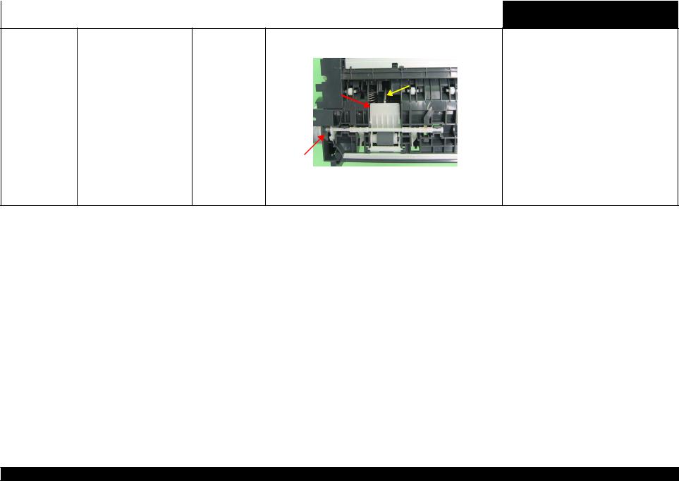
|
L1800 |
Revision A |
||||
|
Table 2-5. Troubleshooting of Multi-feed error |
|||||
|
Occurrence |
Phenomenon Detail |
Faulty Part/Part |
Check Point |
Remedy |
|
|
Timing |
Name |
||||
|
Any time |
During manual double-sided |
ASF Assy |
|
printing, multiple sheets are fed |
||
|
at a time. |
|
1. Check that the Retard Roller Assy is moving properly during the 1. |
Attach the Extension Spring on the back side |
||||
|
feeding operation. |
of the Retard Roller Assy correctly. |
||||
|
Refer to Chapter 3 Retard Roller Assy (P.76). |
|||||
|
Bottom of |
|||||
|
the ASF Assy |
|||||
|
Extension Spring |
|||||
|
Retard Roller |
|||||
|
Assy |
|||||
|
ASF Assy |
|||
|
2. Check that the position of the ASF Guide Roller LDs has been |
2. Adjust the position of the ASF Guide Roller |
||
|
adjusted correctly. |
LDs. |
||
|
Refer to Chapter 3 ASF Assy (P.71). |
Table 2-6. Troubleshooting of Maintenance Request
|
Occurrence |
Phenomenon Detail |
Faulty Part/ |
Check Point |
Remedy |
|
|
Timing |
Part Name |
||||
|
At power-on |
At power-on, the printer does not |
Waste Ink Pads |
1. Using the Adjustment Program, check if the values of the |
1. Replace the Waste Ink Pads and reset the |
|
|
operate at all. |
Protection Counter A and B have exceeded the threshold value. |
Protection Counter A and B value with the |
|||
|
Adjustment Program. |
|||||
|
Troubleshooting |
Overview |
14 |
Confidential

|
L1800 |
Revision A |
||||||||||||
|
Table 2-7. Troubleshooting of Fatal Error |
|||||||||||||
|
Occurrence |
Phenomenon Detail |
Faulty Part/ |
Check Point |
Remedy |
|||||||||
|
Timing |
Part Name |
||||||||||||
|
At power-on |
At power-on, the CR Motor does |
CR Motor |
1. |
Check the CR Motor connector cable for damages. |
1. |
Replace the CR Motor with a new one. |
|||||||
|
not operate at all. |
|||||||||||||
|
2. |
Check if the CR Motor operates normally. |
2. |
Replace the CR Motor with a new one. |
||||||||||
|
3. |
Check that the CR Motor connector cable is connected to the |
3. |
Connect the CR Motor connector cable to the |
||||||||||
|
Main Board connector CN115. |
Main Board connector CN115. |
||||||||||||
CN115
|
Troubleshooting |
Overview |
15 |
Confidential
![]()
|
L1800 |
Revision A |
||||||
|
Table 2-7. Troubleshooting of Fatal Error |
|||||||
|
Occurrence |
Phenomenon Detail |
Faulty Part/ |
Check Point |
Remedy |
|||
|
Timing |
Part Name |
||||||
|
At power-on |
The power-on sequence is |
CR drive |
1. Check that the Carriage Shaft is lubricated with grease. |
1. Wipe the surface of the Carriage Shaft with a |
|||
|
executed but Fatal error is |
mechanism |
dry, soft cloth, and lubricate the Carriage |
|||||
|
displayed. |
Shaft with grease G-71. |
||||||
|
Carriage Shaft |
Refer to Chapter 5 “Maintenance”. |
|
At power-on, the PF Motor does PF Motor |
1. Check that the connector cable of the PF Motor is connected to |
1. Connect the PF Motor connector cable to the |
|
not operate at all. |
the Main Board connector CN116. |
Main Board connector CN116. |
|
CN116 |
|||||
|
2. |
Check the PF Motor connector cable for damages. |
2. |
Replace the PF Motor with a new one. |
||
|
3. |
Check if the PF Motor operates normally. |
3. |
Replace the PF Motor with a new one. |
|
Troubleshooting |
Overview |
16 |
Confidential

|
L1800 |
Revision A |
||||||||||
|
Table 2-7. Troubleshooting of Fatal Error |
|||||||||||
|
Occurrence |
Phenomenon Detail |
Faulty Part/ |
Check Point |
Remedy |
|||||||
|
Timing |
Part Name |
||||||||||
|
At power-on |
At power-on, the APG Motor |
APG Motor |
1. Check that the connector cable of the APG Motor is connected |
1. Connect the APG Motor connector cable to |
|||||||
|
does not operate at all. |
to the Main Board connector CN118. |
the Main Board connector CN118. |
|||||||||
|
CN118 |
||||||||||||||
|
2. |
Check the APG Motor connector cable for damage. |
2. |
Replace the APG Assy with a new one. |
|||||||||||
|
3. |
Check if the APG Motor operates normally. |
3. |
Replace the APG Assy with a new one. |
|||||||||||
|
At power-on, the Pump Motor |
Pump Motor |
1. |
Using a tester, check the resistance value of the Pump Motor. |
1. |
If the resistance value is abnormal, replace the |
|||||||||
|
does not operate at all. |
Value of resistance: 10.3 ± 10% |
Ink System with a new one. |
||||||||||||
|
2. |
Check the Pump Motor connector cable for damages. |
2. |
Replace the Ink System with a new one. |
|||||||||||
|
3. |
Check that the Pump Motor connector cable is connected to the |
3. |
Connect the Pump Motor connector cable to |
|||||||||||
|
Main Board connector CN117. |
the Main Board connector CN117. |
|||||||||||||
CN117
4. Check the Pump Motor connector cable for damages.
4. Replace the Ink System with a new one.
|
Troubleshooting |
Overview |
17 |
Confidential
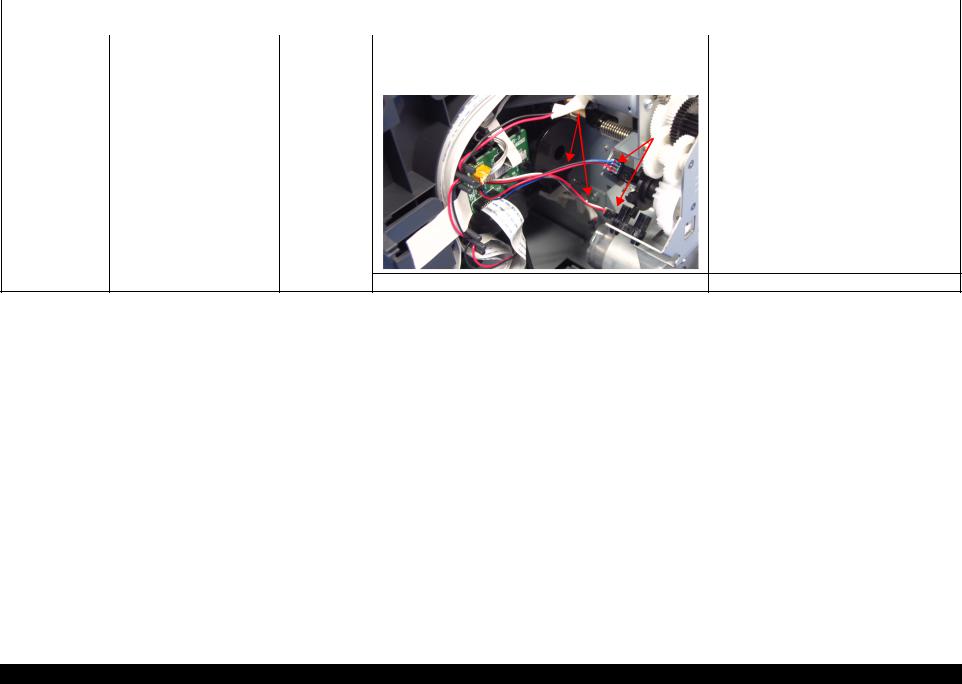
|
L1800 |
Revision A |
|||||||
|
Table 2-7. Troubleshooting of Fatal Error |
||||||||
|
Occurrence |
Phenomenon Detail |
Faulty Part/ |
Check Point |
Remedy |
||||
|
Timing |
Part Name |
|||||||
|
At power-on |
While the power-on sequence is |
APG Sensor |
1. Check the APG Sensor connector cables is connected to the |
1. Connect the APG Sensor connector cables to |
||||
|
being executed, Fatal error is |
APG Sensor connectors. |
the APG Sensor connectors. |
||||||
|
displayed. |
2. Check if the connector cables of the APG Sensor is broken. |
2. Replace the ASF Assy with a new ones. |
||||||
|
APG Sensor connector cables |
||||||||
|
APG Sensors |
|
3. Check the APG Sensors for damages. |
3. Replace the APG Assy with a new one. |
|
Troubleshooting |
Overview |
18 |
Confidential
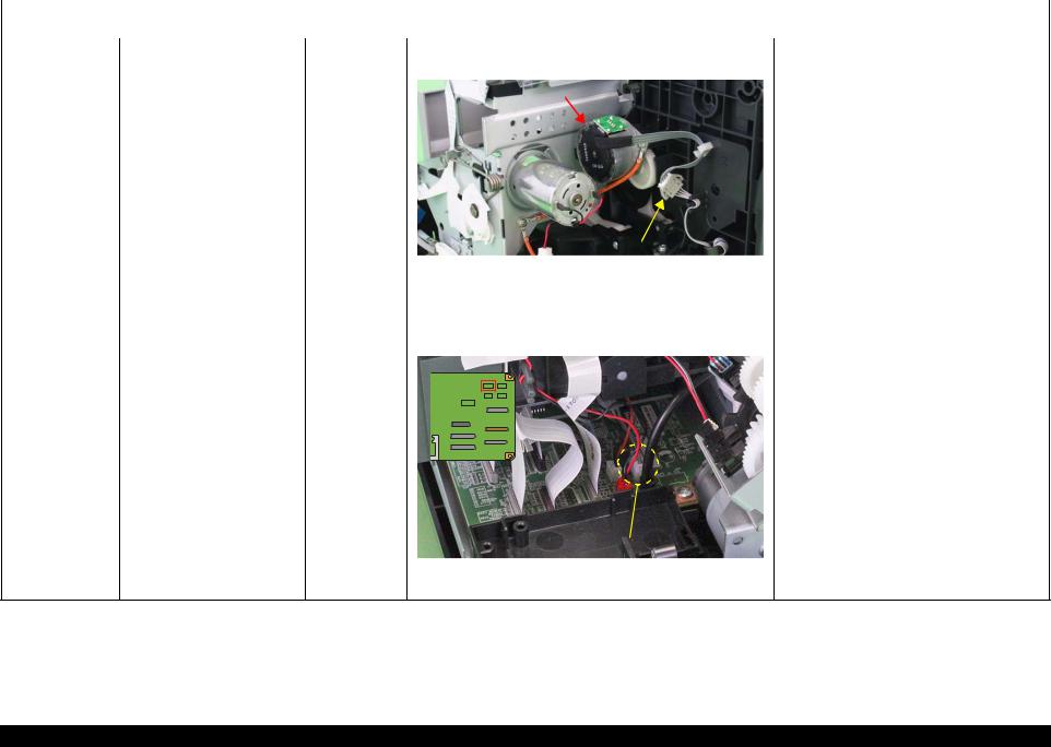
|
L1800 |
Revision A |
||||||
|
Table 2-7. Troubleshooting of Fatal Error |
|||||||
|
Occurrence |
Phenomenon Detail |
Faulty Part/ |
Check Point |
Remedy |
|||
|
Timing |
Part Name |
||||||
|
At power-on |
While the power-on sequence is |
ASF Motor |
1. Check that the connector cable of the ASF Motor is connected |
1. Connect the connector cable of the ASF |
|||
|
being executed, Fatal error is |
to the Relay connector. |
Motor to the Relay connector. |
|||||
|
displayed. |
|||||||
|
ASF Motor |
|
Relay connector |
|||||||||||
|
2. |
Using a tester, check the resistance value of the ASF Motor. |
2. |
If the resistance value is abnormal, replace the |
||||||||
|
Value of resistance: 7.0 ± 10% |
ASF Motor with a new one. |
||||||||||
|
3. |
Check the ASF Motor connector cable for damages. |
3. |
Replace the ASF Motor with a new one. |
||||||||
|
Relay connector 1. |
Check that the Relay connector cable is connected to the Main |
1. |
Connect the Relay connector cable to the |
||||||||
|
cable |
Board connector CN119. |
Main Board connector CN119. |
|||||||||
|
CN119 |
|||
|
2. Check the Relay connector cable for damages. |
2. Replace the Relay connector cable with a new |
||
|
one. |
|
Troubleshooting |
Overview |
19 |
Confidential
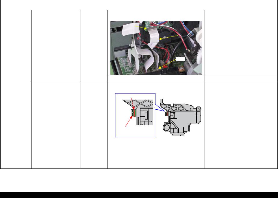
|
L1800 |
Revision A |
||||||||
|
Table 2-7. Troubleshooting of Fatal Error |
|||||||||
|
Occurrence |
Phenomenon Detail |
Faulty Part/ |
Check Point |
Remedy |
|||||
|
Timing |
Part Name |
||||||||
|
At power-on |
While the power-on sequence is |
Relay FFC |
1. Check that the Relay FFC is connected to the Relay Board |
1. Connect the Relay FFC to the Relay Board |
|||||
|
being executed, Fatal error is |
connector CN1 and Main Board connector CN5. |
connector CN1 and Main Board connector |
|||||||
|
displayed. |
CN5. |
||||||||
|
CN1 |
|||||||||
|
Relay FFC |

 CN5
CN5
|
2. Check the Relay FFC for damages. |
2. Replace the Relay FFC cable with a new one. |
|
At power-on, the Carriage Unit |
CR Scale |
1. Check that the CR Scale is inserted in the slit of the CR |
1. Insert the CR Scale into the slit of the CR |
|
moves away from the home |
Encoder Sensor. |
Encoder Sensor. |
|
|
position and bumps against the |
|||
|
right of the Frame, then hits the |
CR Scale |
||
|
left of the Frame. |
|||
|
CR Encoder |
|||
|
Sensor Board |
|
2. |
Check the CR Scale for damages and dirt. |
2. |
Wipe off the dirt completely or replace the CR |
|
|
Scale with a new one. |
||||
|
CR Encoder |
1. |
Check the CR Encoder Sensor for paper dust, etc. |
1. |
Remove the paper dust, etc. from the CR |
|
Sensor Board |
Encoder Sensor. |
|||
|
2. |
Check the CR Encoder Sensor Board for damages. |
2. |
Replace the CR Encoder Sensor Board with a |
|
|
new one. |
|
Troubleshooting |
Overview |
20 |
Confidential

|
L1800 |
Revision A |
||||||||||||
|
Table 2-7. Troubleshooting of Fatal Error |
|||||||||||||
|
Occurrence |
Phenomenon Detail |
Faulty Part/ |
Check Point |
Remedy |
|||||||||
|
Timing |
Part Name |
||||||||||||
|
At power-on |
At power-on, the Carriage Unit |
Sensor FFC |
1. Check that the Sensor FFC is connected to the CR Encoder |
1. Connect the Sensor FFC to the CR Encoder |
|||||||||
|
moves away from the home |
Sensor Board connector and Main Board connector CN9. |
Sensor Board connector and Main Board |
|||||||||||
|
position and bumps against the |
connector CN9. |
||||||||||||
|
right of the Frame, then hits the |
|||||||||||||
|
left of the Frame. |
|||||||||||||
|
CR Encoder Sensor |
|||||||||||
|
Board connector |
CN9 |
||||||||||
|
2. |
Check the Sensor FFC for damages. |
2. |
Replace the Sensor FFC with a new one. |
||||||||
|
At power-on, the PF Roller |
PF Encoder |
1. |
Check that the PF Encoder Sensor Holder is mounted correctly. |
1. |
Install the PF Encoder Sensor Holder |
||||||
|
rotates fast about a half turn. |
Sensor Holder |
correctly. |
|||||||||
|
2. |
Check that the FFC of the PF Encoder Sensor is securely |
2. |
Connect the PF Encoder Sensor FFC to the PF |
||||||||
|
connected to the PF Encoder Sensor Board connector and Relay |
Encoder Sensor Board and Relay Board |
||||||||||
|
Board connector CN6. |
connector CN6. |
||||||||||
|
CN6 |
|
PF Encoder Sensor |
||||
|
Board connector |
||||
|
3. Check the PF Encoder Sensor for paper dust, etc. |
3. |
Remove the paper dust, etc. from the PF |
||
|
Encoder Sensor. |
||||
|
4. Check if the PF Encoder or the FFC is damaged. |
4. |
Replace the PF Encoder with a new one. |
|
Troubleshooting |
Overview |
21 |
Confidential

|
L1800 |
Revision A |
||||
|
Table 2-7. Troubleshooting of Fatal Error |
|||||
|
Occurrence |
Phenomenon Detail |
Faulty Part/ |
Check Point |
Remedy |
|
|
Timing |
Part Name |
||||
|
At power-on |
At power-on, the PF Roller |
PF Scale |
1. Check that the PF Scale is inserted in the slit of the PF Encoder |
1. Install the PF Scale in the slit of the PF |
|
|
rotates fast about a half turn. |
Sensor. |
Encoder Sensor correctly. |
|
2. |
Check the PF Scale for damages and dirt. |
2. |
Replace the PF Scale with a new one. |
|||||||||||
|
During printing |
After receiving a print data, an |
Head FFC |
1. |
Check that the Head FFC and the Sensor FFC are securely |
1. |
Connect the Head FFC and the Sensor FFC to |
||||||||
|
error is displayed on the LED |
Sensor FFC |
connected to the Main Board connectors CN9, CN12, CN13, |
the Main Board connectors CN9, CN12, |
|||||||||||
|
and STM3. |
and CN14. |
CN13, and CN14. |
||||||||||||
 CN9, CN12, CN13, CN14
|
Troubleshooting |
Overview |
22 |
Confidential
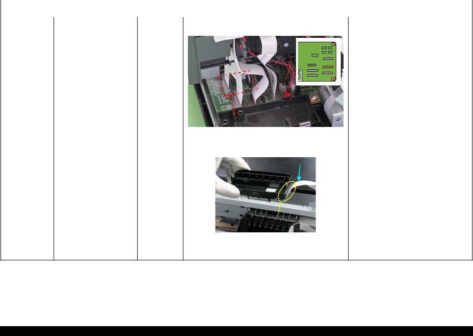
|
L1800 |
Revision A |
||||
|
Table 2-7. Troubleshooting of Fatal Error |
|||||
|
Occurrence |
Phenomenon Detail |
Faulty Part/ |
Check Point |
Remedy |
|
|
Timing |
Part Name |
||||
|
During printing |
After starting to print, ink is not |
Head FFC |
1. Check that the Head FFC is securely connected to the Main |
1. Connect the Head FFC to the Main Board |
|
|
ejected and paper stops midway. |
Board connectors CN12, CN13, and CN14. |
connectors CN12, CN13, and CN14. |
|
CN12, CN13, CN14 |
|||||||||||||||||
|
2. |
Check the Head FFC for damages. |
2. |
Replace the Head FFC with a new one. |
||||||||||||||
|
Head FFC |
1. |
Check that the Head FFC is securely connected to the Print |
1. |
Connect the Head FFC to the CR Relay Board |
|||||||||||||
|
Head connectors. |
connectors CN1 and CN2. |
||||||||||||||||
|
2. |
Connect the Head FFC to the Print Head |
||||||||||||||||
|
Head FFC |
|||||||||||||||||
|
connectors. |
|||||||||||||||||
|
Print Head |
||||||
|
Connector |
||||||
|
2. |
Check the Head FFC for damages. |
3. |
Replace the Head FFC with a new one. |
|||
|
Ink is not ejected from most |
Print Head |
1. |
Check for occurrence of Head Hot. |
1. |
Replace the Print Head with a new one. |
|
|
nozzles. |
|
Troubleshooting |
Overview |
23 |
Confidential

2.1.2 Troubleshooting based on Observed Faults
This section provides troubleshooting procedures based on observed faults such as print quality troubles and abnormal noise.
Table 2-8. Print Quality Troubles
|
Observed Faults |
Details of the Fault |
Faulty Part/ |
Check Point |
Remedy |
|||
|
Part Name |
|||||||
|
Dot missing and |
Inks are not ejected from the |
Ink System Unit |
1. Check for foreign matter around the Seal Rubber on the Cap |
1. Remove the foreign matter around the Seal |
|||
|
mixed colors |
Print Head to the Cap. |
(Cap) |
Unit. |
Rubber completely. |
|||
|
Seal Rubbers |
|||||||
|
Extension Spring, 1.19 IS |
|||||||
|
2. |
Check that the Extension Spring 1.19 IS is correctly installed to |
2. |
Replace the Ink System Unit with a new one. |
||||
|
the Cap Unit. |
|||||||
|
Although inks are ejected from Print Head |
1. |
Run a Nozzle Check, and check the printed pattern if it has |
1. |
After running a Head Cleaning, check the |
|||
|
the Print Head to the Cap, the |
broken lines or missing segments. |
Nozzle Check Pattern again. |
|||||
|
trouble still occurs after |
|||||||
|
executing a cleaning cycle. |
|
Troubleshooting |
Overview |
24 |
Confidential
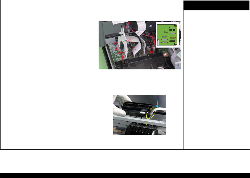
|
L1800 |
Revision A |
||||||||||||||
|
Table 2-8. Print Quality Troubles |
|||||||||||||||
|
Observed Faults |
Details of the Fault |
Faulty Part/ |
Check Point |
Remedy |
|||||||||||
|
Part Name |
|||||||||||||||
|
Dot missing and |
Although inks are ejected from Head FFC |
1. Check that the Head FFC is securely connected to the Main |
1. Connect the Head FFC to the Main Board |
||||||||||||
|
mixed colors |
the Print Head to the Cap, the |
Board connectors CN12, CN13, and CN14. |
connectors CN12, CN13, and CN14. |
||||||||||||
|
trouble still occurs after |
|||||||||||||||
|
executing a cleaning cycle. |
|||||||||||||||
|
CN12, CN13, CN14 |
||||||||
|
2. |
Check the Head FFC for damages. |
2. |
Replace the Head FFC with a new one. If the |
|||||
|
trouble still occurs after replacing it, replace the |
||||||||
|
Print Head with a new one. |
||||||||
|
Head FFC |
1. |
Check that the Head FFC is securely connected to the Print Head |
1. |
Connect the Head FFC to the CR Relay Board |
||||
|
connectors. |
connectors CN1 and CN2. |
|||||||
|
2. |
Connect the Head FFC to the Print Head |
|||||||
|
Head FFC |
||||||||
|
connectors. |
||||||||
|
Print Head |
||
|
Connector |
||
|
2. Check the Head FFC for damages. |
3. Replace the Head FFC with a new one. If the |
|
|
trouble still occurs after replacing it, replace the |
||
|
Print Head with a new one. |
|
Troubleshooting |
Overview |
25 |
Confidential
![]()
|
L1800 |
Revision A |
||||
|
Table 2-8. Print Quality Troubles |
|||||
|
Observed Faults |
Details of the Fault |
Faulty Part/ |
Check Point |
Remedy |
|
|
Part Name |
|||||
|
Dot missing and |
Although inks are ejected from |
Ink System Unit 1. Check if the Cleaner Blade is covered with paper dust or is bent. 1. |
Replace the Ink System Unit with a new one. |
||
|
mixed colors |
the Print Head to the Cap, the |
Cleaner Blade |
|||
|
trouble still occurs after |
|||||
|
executing a cleaning cycle. |
|
Cleaner Blade |
|||||||||||||||||
|
Main Board |
1. |
Check the Main Board for damages. |
1. |
Replace the Main Board with a new one. |
|||||||||||||
|
Horizontal or vertical |
Although inks are ejected from Head FFC |
1. |
Check that the Head FFC is securely connected to the Main |
1. |
Connect the Head FFC to the Main Board |
||||||||||||
|
banding / Getting |
the Print Head to the Cap, the |
Board connectors CN12, CN13, and CN14. |
connectors CN12, CN13, and CN14. |
||||||||||||||
|
smeared |
trouble still occurs after |
||||||||||||||||
|
executing a cleaning cycle. |
|||||||||||||||||
|
CN12, CN13, CN14 |
|||
|
2. Check the Head FFC for damages. |
2. Replace the Head FFC with a new one. If the |
||
|
trouble still occurs after replacing it, replace the |
|||
|
Print Head with a new one. |
|
Troubleshooting |
Overview |
26 |
Confidential

|
L1800 |
Revision A |
||||||
|
Table 2-8. Print Quality Troubles |
|||||||
|
Observed Faults |
Details of the Fault |
Faulty Part/ |
Check Point |
Remedy |
|||
|
Part Name |
|||||||
|
Horizontal or vertical |
Although inks are ejected from Head FFC |
1. Check that the Head FFC is securely connected to the Print Head |
1. Connect the Head FFC to the CR Relay Board |
||||
|
banding / Getting |
the Print Head to the Cap, the |
connectors. |
connectors CN1 and CN2. |
||||
|
smeared |
trouble still occurs after |
2. Connect the Head FFC to the Print Head |
|||||
|
executing a cleaning cycle. |
Head FFC |
||||||
|
connectors. |
|||||||
|
Print Head |
||||||
|
Connector |
||||||
|
2. |
Check the Head FFC for damages. |
3. |
Replace the Head FFC with a new one. If the |
|||
|
trouble still occurs after replacing it, replace the |
||||||
|
Print Head with a new one. |
||||||
|
Print Head |
1. |
Check if the print quality recovers after running a cleaning. |
1. |
Run the cleaning several times. If the trouble |
||
|
still occurs, replace the Print Head with a new |
||||||
|
one. |
||||||
|
Main Board |
1. |
Check the Main Board for damages. |
1. |
Replace the Main Board with a new one. |
|
Troubleshooting |
Overview |
27 |
Confidential

|
L1800 |
Revision A |
||||||||||
|
Table 2-8. Print Quality Troubles |
|||||||||||
|
Observed Faults |
Details of the Fault |
Faulty Part/ |
Check Point |
Remedy |
|||||||
|
Part Name |
|||||||||||
|
Vertical or horizontal |
The printout has banding vertical |
Adjustment |
1. |
For printing in the Bi-D mode, check that the Bi-D Adjustment |
1. Perform Bi-D Adjustment to eliminate |
||||||
|
banding / Color |
to the CR moving direction and |
has been performed properly. |
displacements between the upper and lower |
||||||||
|
shading |
is not evenly colored. |
lines. |
|||||||||
|
Refer to Chapter 4 “Adjustment”. |
|||||||||||
|
Direction of CR |
Print Head |
1. |
Run a Nozzle Check, and check the printed pattern if it has |
1. |
Perform the Head Cleaning, then check the |
||||||
|
movement |
|||||||||||
|
broken lines or missing segments. |
Nozzle Check Pattern. |
||||||||||
|
Refer to Chapter 4 “Adjustment”. |
|||||||||||
|
If the trouble still occurs, replace the Print Head |
|||||||||||
|
with a new one. |
|||||||||||
|
Carriage Shaft |
1. |
Check the surfaces of the Carriage Shaft for foreign matter. |
1. |
Remove foreign matter from the Carriage Shaft. |
|||||||
|
* |
If the trouble still occurs after |
||||||||||
|
2. |
Check that the Carriage Shaft is fully lubricated with grease. |
2. |
Wipe the grease applied to the Carriage Shaft |
||||||||
|
doing all measures described |
|||||||||||
|
with a dry, soft cloth, and then apply G-71 |
|||||||||||
|
in the right-hand columns, |
|||||||||||
|
grease. |
|||||||||||
|
replace the CR Motor with a |
|||||||||||
|
Refer to Chapter 5 “Maintenance”. |
|||||||||||
|
new one. |
|||||||||||
|
3. |
Check that the Carriage Shaft is mounted horizontally. |
3. Reassemble the Carriage Shaft correctly. |
|||||||||
|
4. |
Check the Carriage Shaft for damages. |
4. Replace the Carriage Shaft with a new one. |
|||||||||
|
Narrow stripes of the same width |
Printer Driver and |
1. |
Check if appropriate paper is used in accordance with the Printer |
1. Use the appropriate type of paper in accordance |
|||||||
|
appear horizontally to the CR |
the Paper |
Driver settings. |
with the Printer Driver. |
||||||||
|
moving direction. |
|||||||||||
|
Print Head |
1. |
Run a Nozzle Check, and check the printed pattern if it has |
1. Perform the Head Cleaning, then check the |
||||||||
|
broken lines or missing segments. |
Nozzle Check Pattern. |
||||||||||
|
Direction of CR |
|||||||||||
|
Refer to Chapter 4 “Adjustment”. |
|||||||||||
|
movement |
|||||||||||
|
If the trouble still occurs, replace the Print Head |
|||||||||||
|
with a new one. |
|||||||||||
|
PF Roller Shaft |
1. |
Check the surface of the PF Roller Shaft for foreign matter. |
1. Clean the PF Roller surface carefully. |
||||||||
|
2. |
Check the PF Roller Shaft for damages. |
2. |
Replace the PF Roller with a new one. |
||||||||
|
* |
If the trouble still occurs after |
||||||||||
|
doing all measures described |
|||||||||||
|
in the right-hand columns, |
|||||||||||
|
replace the PF Motor with a |
|||||||||||
|
new one. |
|||||||||||
|
Troubleshooting |
Overview |
28 |
Confidential

|
L1800 |
Revision A |
||||||||||||
|
Table 2-8. Print Quality Troubles |
|||||||||||||
|
Observed Faults |
Details of the Fault |
Faulty Part/ |
Check Point |
Remedy |
|||||||||
|
Part Name |
|||||||||||||
|
Vertical or horizontal |
When printing at 360 dpi, |
Adjustment |
1. |
Check that PF Adjustment has executed properly. |
1. |
Perform PF Adjustment properly. |
|||||||
|
banding / Color |
horizontal banding and color |
Refer to Chapter 4 “Adjustment”. |
|||||||||||
|
shading |
unevenness appears at a constant |
||||||||||||
|
2. |
Check for Dot missing. |
2. |
Replace the Ink System Unit with a new one. |
||||||||||
|
frequency. |
|||||||||||||
|
Star Wheel Rollers traces appear |
Paper EJ Frame |
1. |
Check that the Star Wheel Units have not come off or the Star |
1. |
Install the Star Wheel Units to the Paper EJ |
||||||||
|
in the CR moving direction. |
Assy. |
Wheel Rollers turns normally. |
Frame Assy correctly. |
||||||||||
|
Paper EJ Frame Assy. |
|||||||||||||
|
Star Wheel Units |
||||||||
|
Printout is faint or blurry. |
Printer Driver and |
1. |
Check that adequate paper is used according to the setting of the |
1. |
Use the appropriate type of paper in accordance |
|||
|
the Paper |
Printer Driver. |
with the Printer Driver. |
||||||
|
Print Head |
1. |
Using the Adjustment Program, check that the correct Head ID has |
1. |
Using the Adjustment Program, enter the 24- |
||||
|
been written to the EEPROM. |
digits code of the Head ID to the EEPROM. |
|||||||
|
Refer to Chapter 4 “Adjustment”. |
||||||||
|
The bottom of the printout is not |
Adjustment |
1. |
Check if the Positioning Adjustment of PF Roller Shaft Retainer |
1. |
Make adjustments according to the specified |
|||
|
evenly colored. |
has been performed properly. |
adjustment priority. |
||||||
|
Refer to Chapter 4 “Adjustment”. |
||||||||
|
Paper EJ Roller |
Traces of the Paper EJ Roller |
Printer Driver and |
1. |
Check if appropriate paper is used in accordance with the Printer |
1. |
Use the appropriate type of paper in accordance |
||
|
traces appear on the |
appear on the printed paper. |
the Paper |
Driver settings. |
with the Printer Driver. |
||||
|
printout. |
||||||||
|
Front and Rear |
1. |
Check if the Paper EJ Roller is clean or not. |
1. |
Clean the Paper EJ Roller with a soft cloth. |
||||
|
Paper EJ Roller |
||||||||
|
Assys. |
|
Troubleshooting |
Overview |
29 |
Confidential

|
L1800 |
Revision A |
||||
|
Table 2-8. Print Quality Troubles |
|||||
|
Observed Faults |
Details of the Fault |
Faulty Part/ |
Check Point |
Remedy |
|
|
Part Name |
|||||
|
The printout is |
The non-printed side or the |
Front Paper |
1. Check that heaps of ink are not formed on the Front Paper Guide 1. |
If heaps of ink are formed, replace the Front |
|
|
stained with ink. |
bottom of the printout is dirty |
Guide Pad |
Pad and that the Front Paper Guide Pad is installed securely and |
Paper Guide. If it has been confirmed that the |
|
|
with ink. |
evenly in the setting position. |
Ink pads have risen, reinstall the Front Paper |
|||
|
Guide Pad correctly. |
|
Front Paper Guide Pad |
Front Paper Guide |
||||||||||
|
When the paper size in the sent |
PW sensor |
1. |
Check that the PW Sensor FFC is connected. |
1. |
Connect the PW Sensor FFC. |
||||||
|
print data is larger than the size |
|||||||||||
|
2. |
Check that the PW Sensor is not faulty. |
2. |
Replace the PW Sensor with a new one. |
||||||||
|
of the fed paper, data are printed |
|||||||||||
|
on the Front Paper Guide, |
|||||||||||
|
extending off the paper. |
|||||||||||
|
Ink smudges appear on the blank |
Paper EJ Frame |
1. |
Check the Star Wheel Rollers for ink stain. |
1. |
Clean the Star Wheel Rollers with a soft cloth. |
||||||
|
area of the printout. |
Assy. |
||||||||||
|
Front Paper |
1. |
Check the Front Paper Guide for ink stain. |
1. |
Clean the Front Paper Guide with a soft cloth. |
|||||||
|
Guide |
|||||||||||
|
Front Paper |
1. |
Check if ink heaps are formed on the Front Paper Guide Pad. |
1. |
Replace the Front Paper Guide with a new one. |
|||||||
|
Guide Pad |
|
Troubleshooting |
Overview |
30 |
Confidential

|
L1800 |
Revision A |
||||||||
|
Table 2-8. Print Quality Troubles |
|||||||||
|
Observed Faults |
Details of the Fault |
Faulty Part/ |
Check Point |
Remedy |
|||||
|
Part Name |
|||||||||
|
The printout is |
Ink smudges appear on the blank |
Front and Rear |
1. Check the Front and Rear Paper EJ Roller Assys for ink stain. |
1. Clean the Front and Rear Paper EJ Roller Assys |
|||||
|
stained with ink. |
area of the printout. |
Paper EJ Roller |
with a soft cloth. |
||||||
|
Assys |
Driven Roller Shaft |
||||||||
|
Front Paper EJ Roller Assy |
Rear Paper EJ Roller Assy |
||||||||
|
Driven Roller |
1. |
Check the Driven Roller Shaft for ink stain. |
1. |
Clean the Driven Roller Shaft with a soft cloth. |
|||||
|
Shaft |
|||||||||
|
Ink System Unit |
1. |
Check that wiping operation was performed properly. |
1. |
Install the Cleaner blade correctly or replace it |
|||||
|
with a new one. |
Cleaner Blade
|
Troubleshooting |
Overview |
31 |
Confidential

|
L1800 |
Revision A |
||||
|
Table 2-8. Print Quality Troubles |
|||||
|
Observed Faults |
Details of the Fault |
Faulty Part/ |
Check Point |
Remedy |
|
|
Part Name |
|||||
|
The printout is |
Ink smudges appear on the blank PF Roller Shaft |
1. Check the PF Roller Shaft for ink stain. |
1. Clean the PF Roller Shaft with a soft cloth. |
||
|
stained with ink. |
area of the printout. |
|
PF Roller Shaft |
||||||||
|
The printout is |
Images are printed grainy in all |
Adjustment |
1. |
Check that PG, Bi-D and Head Angular Adjustments have been |
1. |
Make the adjustments according to the |
||
|
grainy. |
print modes. Or the image looks |
Main Board |
made properly. |
specified adjustment priority. |
||||
|
rough. |
Print Head |
Refer to Chapter 4 “Adjustment”. |
||||||
|
2. |
Print the adjustment check patterns and check if they are grainy. 2. If the images look still grainy after adjustment, |
|||||||
|
replace the Main Board with a new one. |
||||||||
|
When printed at 5760 dpi, the |
Adjustment |
1. |
After making sure that PG, Bi-D and Head Angular Adjustments |
1. |
Make the adjustment according to the specified |
|||
|
printed images are poor or |
Main Board |
have been made correctly, check whether PW Sensor has been |
adjustment priority. |
|||||
|
grainy. |
Print Head |
adjusted properly. |
Refer to Chapter 4 “Adjustment”. |
|||||
|
2. |
Print the adjustment check patterns and check if the printed |
2. |
If the image quality does not improve after the |
|||||
|
images are still poor or grainy. |
adjustment, replace the Print Head and Main |
|||||||
|
Board in this order, and check the image |
||||||||
|
graininess. |
||||||||
|
Regarding hue of |
The whole image is reddish. |
Adjustment |
1. |
Check if the PG has been adjusted properly. |
1. |
Make the adjustment according to the specified |
||
|
images |
Print Head |
adjustment priority. |
||||||
|
Refer to Chapter 4 “Adjustment”. |
||||||||
|
2. |
Check that Bi-D and Head Angular Adjustments have been |
2. |
Make the adjustments according to the |
|||||
|
made properly. |
specified adjustment priority. |
|||||||
|
Refer to Chapter 4 “Adjustment”. |
||||||||
|
3. |
Print the adjustment check patterns and check the image color. |
3. |
If the image color does not change after |
|||||
|
adjustment, replace the Print Head with a new |
||||||||
|
one. |
|
Troubleshooting |
Overview |
32 |
Confidential

|
L1800 |
Revision A |
|||||
|
Table 2-8. Print Quality Troubles |
||||||
|
Observed Faults |
Details of the Fault |
Faulty Part/ |
Check Point |
Remedy |
||
|
Part Name |
||||||
|
Borderless Printing |
Cannot make a borderless |
PW sensor |
1. |
Check if the paper dust or scrap of the paper is attached to the |
1. |
Remove the paper dust or scrap of the paper. |
|
printing (The printer prints with |
Front Paper Guide. |
|||||
|
margins despite the borderless |
||||||
|
2. |
Check that PW adjustment has executed properly. |
2. |
If the borderless printing still can not be made |
|||
|
setting). |
||||||
|
after the adjustment, replace the PW Sensor |
||||||
|
with a new one. |
||||||
|
Refer to Chapter 4 “Adjustment”. |
||||||
|
Pattern misalignment |
The vertical lines are not aligned |
Adjustment |
1. |
Check that BAND printing adjustment has executed properly. |
1. |
Make the adjustment according to the specified |
|
for vertical lines and |
at monochrome draft printing. |
adjustment priority. |
||||
|
such |
Refer to Chapter 4 “Adjustment”. |
|||||
|
Blank print |
Inks are not ejected from Print |
Valve |
1. |
Check that Valve of Ink Tank opens. |
1. |
Open Valve. |
|
Head even though Carriage |
(Valve Lever) |
|||||
|
moves and paper is fed. |
||||||
|
Ink Tube |
1. |
Check that Ink Tubes are not crumpled. |
1. |
Release crumpled Ink Tube. |
||
|
Adapter |
1. |
Check that Ink Tube connections are complete. |
1. |
Reassemble Ink Tubes and compete their |
||
|
Ink Tube |
connections. |
|||||
|
Tube Joint |
||||||
|
Ink Supply Tank |
||||||
|
Table 2-9. Abnormal Noise |
||||||
|
Occurrence Timing |
Details of the Fault |
Faulty Part/ |
Check Point |
Remedy |
||
|
Part Name |
||||||
–Printing operation is performed normally but abnormal noise is produced at power-on or during operations.
|
Adjustment |
1. |
Check that PF Belt Tension Adjustment has been executed |
1. |
Make the adjustment according to the specified |
|
properly. |
adjustment priority. |
|||
|
Refer to Chapter 4 “Adjustment”. |
||||
|
Carriage Shaft |
1. |
Check that the Carriage Shaft is fully lubricated with grease. |
1. |
Wipe the grease applied to the Carriage Shaft |
|
with a dry, soft cloth, and then apply grease (G- |
||||
|
71). |
||||
|
Refer to Chapter 5 “Maintenance”. |
|
Troubleshooting |
Overview |
33 |
Confidential

C H A P T E R
3
DISASSEMBLY AND ASSEMBLY
Confidential

3.1 Overview
This chapter describes procedures for disassembling and assembling this product. Unless otherwise specified, the disassembled units or main components can be reassembled by reversing the disassembling procedure.
WARNINGs must be followed to avoid personal injury or death.
CAUTIONs must be followed to avoid damaging the printer or test equipment.
ADJUSTMENT REQUIRED indicates that specific mandatory adjustments must be carried out to complete the repair.
CHECK POINTs emphasize a particularly important process or procedure.
REASSEMBLY notes provide helpful tips on reassembly procedures, especially when correct reassembly differs from simple reverse-assembly.
Before starting your work, always read the precautions described in the next section.
3.1.1 Precautions
Before starting the disassembling/reassembling work of this product, always read the following “WARNING” and “CAUTION” carefully.
WARNING Before starting the disassembling/reassembling work of this product, always disconnect the power cable.
When the power supply cable must be connected for voltage measurement or like, be extremely careful not to get an electric shock and follow the procedures in this manual to do your work.
Wear protective goggles to protect your eyes from ink. If ink gets in your eyes, wash your eyes with clean water and see a doctor.
To prevent injury from sharp metal edges, always wear gloves for disassembly and reassembly.
If ink has adhered to your skin, wash it with soap and water. If it has caused skin irritation, see a doctor.
To protect the microprocessors and circuitry, use static discharge equipment, such as anti-static wrist straps when accessing the internal components.
|
CAUTION |
Use only the recommended tools for disassembly, reassembly |
|
and adjustment. |
|
|
Refer to Table 3-1 “List of Tools”. |
|
|
|
Tighten screws to the specified torques. |
Use the specified lubricants and adhesives. Refer to Chapter 5 “Maintenance”.
Make the necessary adjustments under the instructions given for disassembling.
Refer to Chapter 4 “Adjustment”.
When using compressed air products; such as air duster, for cleaning during repair and maintenance, the use of such products containing flammable gas is prohibited.
|
Disassembly And Assembly |
Overview |
35 |
Confidential
![]()
3.1.2 Tools
The following table indicates the tools recommended for use for disassembly, reassembly and adjustment.
Table 3-1. List of Tools
|
Tool Name |
Code |
|
Phillips Screw Driver, No.1 |
1080530 |
|
Phillips Screw Driver, No.2 |
— |
|
Flathead Screwdriver |
— |
|
Tweezers |
— |
|
Needle nose pliers |
— |
|
Nipper |
— |
|
Acetate tape |
1003963 |
|
PF Tension Measuring Tool |
1294120 |
|
Penlight |
— |
|
Strong tape |
1032813 |
Note : All of the tools listed above are commercially available. EPSON provides the tools listed with EPSON tool code.
3.1.3 Screws
The following table lists the screws used in this product. When disassembling and reassembling the printer, refer to the following table and use the specified screws in the specified positions.
Table 3-2. List of Screw Types
|
No. Name |
No. Name |
||
|
1) C.B.P. M3x10 |
11) C.C. M3x4 |
||
|
2) |
C.B.S. M3x6 |
12) |
C.P.B. (P1) M1.7×5 |
|
3) |
C.B.S. (P2) M3x10 |
13) |
C.B.P. M2.6×5 |
|
4) |
C.B.P. M3x8 |
14) C.P. M3x4 |
|
|
5) |
C.B.S. M3x8 |
15) |
C.B.S. (P2) M3x8 |
|
6) |
C.B.S. (P4) M3x8 |
16) |
C.B.P. M2x8 |
|
7) |
C.B.P. M2.6×8 |
17) |
C.B. M3x6 |
|
|
C.B.S. (P4) M3x6 |
18) |
C.B.P. 3×12 |
|
9) C.B.P. M3x6 |
19) C.B. M3x4 |
||
|
10) C.B.S. M3x4 |
|||

|
Disassembly And Assembly |
Overview |
36 |
Confidential

3.1.4 Checks and Precautions before Disassembling
3.1.4.1 Factors which Affect the Print Quality
HOW TO PLACE THE INK TANK ASSY WHEN DISASSEMBLING/ REASSEMBLING
The Ink Supply Tank Assy of this printer has an air release hole on the upper part. The ink in the ink tanks is vented to the atmosphere through this hole to stabilize ink supply to the Printhead. If the Ink Supply Tank Assy is tilted, the ink in the tanks may leak from the air release hole. If the air release hole is sealed up with the leaked ink, ventilation to the atmosphere cannot be done properly and the print quality may be affected adversely.
In order to prevent this from happening, make sure to place the Ink Supply Tank Assy as shown below after removing it.
OK
|
Ink Supply Tank Assy |
Ink Supply Tank Assy |

 Air release hole
|
NG |
Do not place the Ink Supply Tank Assy with |
|||
|
Ink Supply Tank Assy |
||||
|
the air release holes down or to one of the |
||||
sides. Otherwise, the ink in the Ink Supply Tank Assy may come up to the holes and may leak or the print failure may occur.
Figure 3-1. How to Place the Ink Tank Assy
3.1.4.2Factors which Affect the Safety of Service Personnel such as Ink Leakage during Operation
Ink may spill when removing the following parts from L1800.
This section describes the parts that may cause ink spill and the means to minimize the ink spill when removing the parts.
THE PARTS THAT MAY CAUSE INK SPILL WHEN REMOVING
|
Parts |
When ink may spill |
Location |
|
|
Joint |
Removing the Ink Supply Tank Tube Assy |
A |
|
|
/ Ink Supply Tube Assy from the Joint |
|||
|
Ink Supply |
Removing the tubes of the Ink Supply |
A, B |
|
|
Tank Assy |
Tank Tube Assy from the Joint |
||
|
Removing the tubes of the Ink Supply |
|||
|
Tank Tube Assy from the Ink Supply |
|||
|
Ink Supply |
|||
|
Tank Tube Assy |
Tank Assy |
||
|
(w/Valve Assy) |
|||
|
Adapter |
Removing the Ink Supply Tube Assy from |
C |
|
|
the Adapter |
|||
|
Ink Supply |
Removing the Ink Supply Tank Tube Assy |
A, C |
|
|
Tube Assy |
/ Ink Supply Tube Assy from the Joint |
||
|
Removing the Ink Supply Tube Assy |
|||
|
from the Adapter |
|||
|
Adapter |
Joint |
Ink Supply Tank Assy |
|
C |
|
A |
||
|
B |
||
|
Ink Supply Tube Assy |
Ink Supply Tank Tube Assy |
|
Figure 3-2. Location
|
Disassembly And Assembly |
Overview |
37 |
Confidential

MEANS DO TO MINIMIZE THE INK SPILL
CAUTION Even observing the points described in this section, ink may spill in the following situations. Therefore, be careful not to contaminate
the inside of the printer or its surroundings by preparing the container to receive the leaked ink, or the like.
When removing the Ink Supply Tank Tube Assy (w/Valve Assy), some ink will spill from both ends of the tube even the Valve Lever is closed.
When removing the Ink Supply Tube Assy, all the ink in the tube will spill.
Before disassembling, confirm that the printer is in the following condition.
Choke Valve is closed
CAUTION Do not turn the Valve Lever too much when closing the Choke Valve, otherwise, the Valve Lever and/or Valve Assy may get
damaged.
Before disassembling:
Turn the Valve Lever and be sure to close the Choke Valve.
After reassembling is complete:
Open the Choke Valve to perform the print inspection.
Before returning the printer to the user after repairing:
Make sure to turn the Valve Lever up to the choke position to close the Choke Valve before packing the printer.
|
Open position |
Choke position |
Choke position |
|
(When checking with the |
||
|
Valve Lever removed.) |
||
|
Valve shaft |
|
Valve Lever |
Valve Lever |
Choke Valve shaft is secured more tightly |
|
in Choke position than in Open position. |
Figure 3-3. Opening/closing the Choke Valve
DISCHARGING INK FROM THE INK SUPPLY TANK
Discharging ink is recommended only when disconnecting the Ink Supply Tank Tube Assy from the Ink Supply Tank. Before performing the above disconnection, discharge ink from the Ink Supply Tank as follows.
Necessary tools
Containers (x 6) for each discharged ink
Injector (with a tip of 3.2 mm)
Tube (capable to be connected to the joint)
|
CHECK |
When disconnecting the Ink Supply Tube/Ink Supply Tank |
|
POINT |
Tube from the Joint, ink may leak from the ink tube. Prepare |
|
a container to receive the leaking ink to prevent the product |
|
|
from getting contaminated by the leaked ink. |
Prior to the following steps, connect the injector with the tube, and then discharge ink according to the procedure.
Discharging procedure
1.Remove the Upper Housing Support Assy.(p.52)
2.With the choke value closed (p.38), place the Ink Supply Tank Assy on a place where its bottom is higher than the top of the Printhead.
3.Prepare a container for ink to discharge, then disconnect the Ink Supply Tube from the joint and put its tip into the container for the ink.
4.Open the choke valve to discharge the ink in the Ink Supply Tank Assy to the container.
|
Container for discharged ink |
Ink Supply Tank Assy |
Figure 3-4. Discharging Ink (1)
|
Disassembly And Assembly |
Overview |
38 |
Confidential

|
5. Close the choke valve, then connect the tube connected with the injector to the |
CHECK |
|
|
Ink Supply Tank Tube. |
||
|
POINT |
6.Open the choke valve again, and suck up the remaining ink in the Ink Supply Tank into the injector.
|
Joint |
Ink Supply Tank Tube |
|
Tube |
Injector |
|
(tip of 3.2 mm) |
Figure 3-5. Discharging Ink (2)
7.Repeat Step 3 to Step 7 for all ink tanks to discharge all ink in the Ink Supply Tank.
It is recommended that the ink in the Ink Supply Tank should be discharged completely before proceeding to disassembling/ reassembling.
After all the reassembling work is complete, the discharged ink of each color should be refilled back to the Ink Supply Tank before performing the adjustment. Confirm the colors indicated on the film of the Ink Supply Tank so as not to mistake them, and make sure to refill each ink back to the correct tank from the corresponding ink supply hole.
Ink Supply Tank Assy
Ink supply hole
|
Disassembly And Assembly |
Overview |
39 |
Confidential

3.1.5 Protection for Transportation
Before packing the printer for returning it to the user, secure it at the specified points with strong tape to avoid damaging the printer or ink leakage during transport, and make sure to check the points as follows.
Securing each parts
Secure the following parts with strong tape.
Securing the Carriage Unit
Prepare a piece of strong tape (length: 205 ± 2 mm, width: 22 mm).
1.Confirm that the Carriage Unit is locked in the home position.
2.Attach the unfolded end of strong tape (fold the other end back 5 mm) on the bottom left of the Adapter Cover.
3.Move the carriage in the direction of the arrow (130 digit side) in Figure 3-6 until it touches the Carriage Lock.
4.Pull the tape toward the right side of the housing and attach it tightly along the shapes of the housing as shown in Figure 3-6 to secure the Carriage Unit.
|
Step2 |
Adapter Cover |
Carriage Unit |
|
Attach the tape on the |
|
|
housing to leave any gap. |
Folded end |
Figure 3-6. Securing the Carriage Unit
Securing the Ink Tank
Prepare two pieces of strong tape (length: 90 ± 2 mm, width: 22 mm).
1.Install the Ink Supply Tank Assy to the printer.
2.Secure the Decoration Plate Right, Ink Supply Tank Assy, and Top Cover with strong tape (x2).
|
Strong tape |
Decoration Plate Right |
Strong tape |
|
Ink Supply Tank Assy |
Top Cover |
Folded end |
Figure 3-7. Securing the Ink Supply Tank Assy
|
Disassembly And Assembly |
Overview |
40 |
Confidential
 Loading…
You can only view or download manuals with
Sign Up and get 5 for free
Upload your files to the site. You get 1 for each file you add
Get 1 for every time someone downloads your manual
Buy as many as you need
Service manual для принтера Epson L1800
Данная подробная инструкция поможет вам в разборке и обслуживании принтера Epson L1800.
Соблюдайте правила безопасности при работе с электрооборудованием - отключайте принтер от источника питания перед началом ремонтных работ. Работа должна выполнятся квалифицированным персоналом с соответствующими знаниями.
 Руководство подготовлено производителем, ни сайт, ни производитель не несет никакой ответственности за ущерб вследствие любых неточностей при выполнении указанных в данном Руководстве действий.
 Вся документация по обслуживанию предоставляется только для информации. Вся документация по техническому обслуживанию предназначена только для использования обученным и сертифицированным сервисным персоналом. Обслуживание оборудования, модулей, элементов или частей самостоятельно может аннулировать гарантийные обязательства, в отношении обслуживания данного оборудования.
 Соблюдайте правила безопасности при работе с электрооборудованием - отключайте принтер от источника питания перед началом ремонтных работ. Работа должна выполнятся квалифицированным персоналом с соответствующими знаниями.
Руководство подготовлено производителем, ни сайт, ни производитель не несет никакой ответственности за ущерб вследствие любых неточностей при выполнении указанных в данном Руководстве действий.
Вся документация по обслуживанию предоставляется только для информации. Вся документация по техническому обслуживанию предназначена только для использования обученным и сертифицированным сервисным персоналом. Обслуживание оборудования, модулей, элементов или частей самостоятельно может аннулировать гарантийные обязательства, в отношении обслуживания данного оборудования.
Соблюдайте правила безопасности при работе с электрооборудованием - отключайте принтер от источника питания перед началом ремонтных работ. Работа должна выполнятся квалифицированным персоналом с соответствующими знаниями.
Руководство подготовлено производителем, ни сайт, ни производитель не несет никакой ответственности за ущерб вследствие любых неточностей при выполнении указанных в данном Руководстве действий.
Вся документация по обслуживанию предоставляется только для информации. Вся документация по техническому обслуживанию предназначена только для использования обученным и сертифицированным сервисным персоналом. Обслуживание оборудования, модулей, элементов или частей самостоятельно может аннулировать гарантийные обязательства, в отношении обслуживания данного оборудования.Инструкции (руководства пользователя, user guide) для пользователей как правило содержат общую информацию об устройстве, его особенностях и характеристиках, а также информацию о настройке, подключении и расходных материалах.
Сервисные руководства (сервис-мануалы, service manuals) предназначены для технических специалистов и содержат подробную техническую информацию об устройстве. Как правило в сервис-мануале есть подробная иллюстрированная инструкция о разборке, ремонте и настройке устройства.
Ссылки ниже ведут на сайты-файлообменники.
Сервис мануал для Epson L1800 (pdf, 13,5 Мб)Подробный сервис-мануал (service manual) для принтеров Epson L1800 в формате PDF. |
Скачать с dfiles.ru |
Руководство пользователя (pdf, 1.31 Mb)Руководство, в котором в доступной форме изложены основные характеристики устройства и правила его эксплуатации |
Скачать с epson.ru |
Руководство по установке (pdf, 509.85 Kb)Подробное описание процесса первоначальной установки и настройки устройства. |
Скачать с epson.ru |
![]()
EPSON COLOR INKJET L1800 SM

Type:  (PDF)
(PDF)
Size
13.4 MB
Page
149
Category
PRINTER
SERVICE MANUAL
If you get stuck in repairing a defective appliance
download
this repair information for help. See below.
Good luck to the repair!
Please do not offer the downloaded file for sell only
use it for personal usage!
Looking for similar epson manual?
Document preview [1st page]

Click on the link for free download!
Document preview [2nd page]

Click on the link for free download!
Please tick the box below to get download link:
- Also known:
EPSON COLOR INKJET L-1800 L1800 1800
- If you have any question about repairing write your question to the Message board. For this no need registration.
- If the site has helped you and you also want to help others, please Upload a manual, circuit diagram or eeprom that is not yet available on the site.
Have a nice Day! - Please take a look at the below related repair forum topics. May be help you to repair.
Warning!
If you are not familiar with electronics, do not attempt to repair!
You could suffer a fatal electrical shock! Instead, contact your nearest service center!
Note! To open downloaded files you need acrobat reader or similar pdf reader program. In addition,
some files are archived,
so you need WinZip or WinRar to open that files. Also some files are djvu so you need djvu viewer to open them.
These free programs can be found on this page: needed progs
If you use opera you have to disable opera turbo function to download file!
If you cannot download this file, try it with CHROME or FIREFOX browser.
Relevant PRINTER forum topics:
Sziasztok. A minap behoztak a fent nevezett nyomtatobol a fekete kazettat ujratoltesre. Rendelesre jott a toner is es a csip is. A furcsa jelenseg a kovetkezo: kiirja, hogy «missing toner Y K», annak ellenere, hogy mind a 4 kazetta bent van. A szervizkonyv lehetseges oknak azt irja, hogy «nem engedelyezett kazetta» hasznalata. Ha kiveszem a fekete kazettat, kiirja hogy missing toner K — helyesen. Ha beteszem a feketet es kiveszem a sargat, ugyancsak a feketet keri, annak ellenere, hogy a fekete bent van, a sarga meg nincs. Talalkozott valaki hasonlo jelenseggel? Avagy ez is csak eredeti kazettakal megy?
Üdv a tanyasiaknak.
Adott egy 7400-as gyáripatronokkal. A sárgánál hibát jelez, a többi jó.
Adott egy 7450-es, utángyártottakkal, a kéket hibásnak jelzi, de lötyög benne a tinta, a többi jó.
A 7400-ból a kéket átrakom ami ott jó volt,akkor is hibásnak jelzi a 7450-es
A 7450-ből a jó sárgát átrakom a 7400-ba akkor is hibásnak jelzi.
Lehetséges, hogy az érintkezők hibásak, vagy a csip nem észleli?
No de mind a kettőnél? Hogy lehetne kitalálni mi a heppje? Vagy ez Epson, azért?
Köszi.
Üdvözlök mindenkit!
Egy olyan kérdésem lenne, hogy van a fent említett epson stylus c62-s nyomtatóm! átalakítottam ,hogy bevegye a sík lapot, mert kartonra kell nyomtatnom, és amikor beteszem a papírt és elindítom a nyomtatást hiába nyomom az optokapu közé a papír által mozgatott műanyagot nem akar nyomtatni és azt írja kifogyott a papír ! Tudnátok erre a problémára valamilyen megoldást? Ez az optokapu érzékeli a nyomtatófej végállását !
Helló, Epson Stylus SX210 nnyomtatóban minden szín majdnem tele van, kivéve a feketét, az azt hiszem teljesen üres. Régen felejánlotta, hogy kinyomtatja az adott oldalt más színek bekeverésével, de most nem teszi. Automatikusan a patron cseréjéhez irányít. A baj az, hogy hamarosan szeretném eldni a nyomtatót, de így nem tudom megmutatni, hogy működik. Próbáltam csak sárga szöveget nyomtatni, de arra is a patroncserét adja ki. Sehol nem találok, olyan beállítást, hogy autómatikusan keverjen abból, ami van, és nem értem amúgy miért nem ajánlja fel. Elvileg teljesen jól működik, csak kifogyott a fekete festék.
Köszönettel:
Bandi
Similar manuals:
If you want to join us and get
repairing help
please sign in or sign up by completing a simple electrical test
or write your question to the Message board without registration.
You can write in English language into the forum (not only in Hungarian)!
E-Waste Reduce