Гидравлический экскаватор 320 Руководство пользователя

Технические спецификации
Конфигурации и функции могут различаться в зависимости от региона. Пожалуйста, проконсультируйтесь с вашим дилером Cat ® о доступности в вашем регионе.
Гидравлический экскаватор 320 Технические характеристики
ДВИГАТЕЛИ

- Модель 320 соответствует экологическим стандартам Tier 4 Final Агентства по охране окружающей среды США.
- Рекомендуется для использования на высоте до 4500 м (14,764 3000 футов) над уровнем моря со снижением мощности двигателя на высоте более 9,842.5 м (XNUMX футов).
- Полезная мощность проверена в соответствии с ISO 14396: 2002. Стандарты, действующие на момент изготовления.
- Полезная мощность, доступная на маховике, когда двигатель оснащен вентилятором, воздухоочистителем, системой очистки выхлопных газов и генератором с частотой вращения двигателя 2,200 об / мин.
- Номинальная частота вращения 2,200 об / мин.
Механизм качания

Массы
Эксплуатационная масса — 22 500 кг — 49,600 XNUMX фунтов
- Удлиненная стрела, рукоять R2.9 (9 футов 6 дюймов), ковш HD 1.19 м3 (1.56 ярда3), башмаки с тройными грунтозацепами 790 мм (31 дюйм), противовес 4.2 т (10.400 XNUMX фунтов).
трек

Диск

Гидравлическая система

Емкости для пополнения запасов

Стандартный

Звуковое представление
ISO 6395: 2008 (внешний) — 99 дБ (A)
ISO 6396: 2008 ISO 6396 (внутри кабины) — 70 дБ (A)
- Защита органов слуха может потребоваться при работе с открытым рабочим местом оператора и кабиной (при неправильном обслуживании или при открытых дверях / окнах) в течение длительного времени или в шумной среде.
Рабочий вес и давление на грунт

Вес основных компонентов

Размеры
Все размеры являются приблизительными и могут отличаться в зависимости от выбранного ковша.

Рабочие диапазоны
Все размеры являются приблизительными и могут отличаться в зависимости от выбранного ковша.


Грузоподъемность удлиненной стрелы — противовес: 4.2 м (9,300 фунтов) — без ковша, подъем тяжелых грузов: включен

* Указывает, что нагрузка ограничена гидравлической грузоподъемностью, а не опрокидывающей нагрузкой. Вышеуказанные нагрузки соответствуют стандарту грузоподъемности гидравлических экскаваторов ISO 10567: 2007. Они не превышают 87% гидравлической грузоподъемности или 75% опрокидывающей нагрузки. Вес всех подъемных приспособлений следует вычесть из вышеуказанной грузоподъемности. Грузоподъемности основаны на машины, стоящей на прочной ровной поверхности. Использование точки крепления рабочего инструмента для перемещения / подъема предметов может повлиять на подъемную способность машины.
Грузоподъемность остается на уровне ± 5% для всех имеющихся башмаков гусеницы.
Для получения информации о конкретном продукте всегда обращайтесь к соответствующему Руководству по эксплуатации и техническому обслуживанию.
Грузоподъемность удлиненной стрелы HD — противовес: 4.7 м (10,400 фунтов) — без ковша, подъем тяжелых грузов: включен

* Указывает, что нагрузка ограничена гидравлической грузоподъемностью, а не опрокидывающей нагрузкой. Вышеуказанные нагрузки соответствуют стандарту грузоподъемности гидравлических экскаваторов ISO 10567: 2007. Они не превышают 87% гидравлической грузоподъемности или 75% опрокидывающей нагрузки. Вес всех подъемных приспособлений следует вычесть из вышеуказанной грузоподъемности. Грузоподъемности основаны на машины, стоящей на прочной ровной поверхности. Использование точки крепления рабочего инструмента для перемещения / подъема предметов может повлиять на подъемную способность машины.
Грузоподъемность остается на уровне ± 5% для всех имеющихся башмаков гусеницы.
Для получения информации о конкретном продукте всегда обращайтесь к соответствующему Руководству по эксплуатации и техническому обслуживанию.
Грузоподъемность стрелы со сверхдлинным вылетом стрелы — противовес: 4.7 м (10,400 фунтов) — без ковша

* Указывает, что нагрузка ограничена гидравлической грузоподъемностью, а не опрокидывающей нагрузкой. Вышеуказанные нагрузки соответствуют стандарту грузоподъемности гидравлических экскаваторов ISO 10567: 2007. Они не превышают 87% гидравлической грузоподъемности или 75% опрокидывающей нагрузки. Вес всех подъемных приспособлений следует вычесть из вышеуказанной грузоподъемности. Грузоподъемности основаны на машины, стоящей на прочной ровной поверхности. Использование точки крепления рабочего инструмента для перемещения / подъема предметов может повлиять на подъемную способность машины.
Грузоподъемность остается на уровне ± 5% для всех имеющихся башмаков гусеницы.
Для получения информации о конкретном продукте всегда обращайтесь к соответствующему Руководству по эксплуатации и техническому обслуживанию.
Технические характеристики и совместимость ковшей

Компания Caterpillar рекомендует использовать соответствующие рабочие инструменты, чтобы клиенты получали максимальную отдачу от нашей продукции. Использование навесного оборудования, включая ковши, которые не соответствуют рекомендациям или спецификациям компании Caterpillar в отношении веса, размеров, расхода, давления и т. Д. может привести к неоптимальной производительности, включая, помимо прочего, снижение производительности, стабильности, надежности и долговечности компонентов. Неправильное использование рабочего орудия, приводящее к подметанию, поднятию, скручиванию и / или захвату тяжелых грузов, сокращает срок службы стрелы и рукояти.

Компания Caterpillar рекомендует использовать соответствующие рабочие инструменты, чтобы клиенты получали максимальную отдачу от нашей продукции. Использование навесного оборудования, включая ковши, которые не соответствуют рекомендациям или спецификациям компании Caterpillar в отношении веса, размеров, расхода, давления и т. Д. может привести к неоптимальной производительности, включая, помимо прочего, снижение производительности, стабильности, надежности и долговечности компонентов. Неправильное использование рабочего орудия, приводящее к подметанию, поднятию, скручиванию и / или захвату тяжелых грузов, сокращает срок службы стрелы и рукояти.
Руководство по предложениям вложений
Не все вложения доступны во всех регионах. По вопросу конфигураций, доступных в вашем регионе, обратитесь к своему дилеру Cat.

Не все вложения доступны во всех регионах. По вопросу конфигураций, доступных в вашем регионе, обратитесь к своему дилеру Cat.

Не все вложения доступны во всех регионах. По вопросу конфигураций, доступных в вашем регионе, обратитесь к своему дилеру Cat.

Технические характеристики большого пальца

^ Максимальная полезная нагрузка ковша зависит от массы большого пальца, длины рукояти, противовеса и типа сцепного устройства; выберите ведро, используя руководство по подбору ковшей.
Стандартное и дополнительное оборудование
Стандартное и дополнительное оборудование может отличаться. За подробностями обращайтесь к своему дилеру Cat.


Комплект и принадлежности, установленные дилером
Вложения могут отличаться. За подробностями обращайтесь к своему дилеру Cat.
САВ
- Радиальный нижний дворник
- Электрическая педаль LH / RH для управления инструментом
- Комплект заднего стекла с двойным выходом
- Защита от дождя и крышка фонаря кабины
- 75 мм (3 ″) убирающийся ремень безопасности
БЕЗОПАСНОСТЬ И ОХРАНА
- Брелок Bluetooth
СЕРВИС И ТЕХНИЧЕСКОЕ ОБСЛУЖИВАНИЕ
- Держатель шприца для смазки
ЭЛЕКТРИЧЕСКИЕ
- Подключение к сети от внешнего источника
ГВАРДИЯ
- Боковой резиновый бампер
- Система защиты от падающих предметов (не совместима с кожухом кабины, защитой от дождя)
- Сетчатый кожух спереди (не совместим с кожухом кабины, защитой от дождя)
- Решетка передняя нижняя половина
- Полная защита от вандализма
Чтобы получить более полную информацию о продуктах Cat, услугах дилеров и отраслевых решениях, посетите нас на сайте web at www.cat.com
© Caterpillar, 2020 г.
Все права защищены
Материалы и технические характеристики могут быть изменены без предварительного уведомления. Представленные на фотографиях машины могут включать дополнительное оборудование. Чтобы узнать о доступных вариантах, обратитесь к дилеру Cat.
CAT, CATERPILLAR, LET’S DO THE WORK, соответствующие логотипы, «Caterpillar Corporate Yellow», «Power Edge» и Cat «Modern Hex», а также идентификационные данные корпорации и ее продукции, используемые здесь, являются товарными знаками Caterpillar и не могут быть используется без разрешения.
AEXQ2161-04 (11-2020)
Заменяет AEXQ2161-03.
Номер сборки: 07D
(Северная Америка)
![]()
Гидравлический экскаватор 320 Руководство пользователя — Оптимизированный PDF
Гидравлический экскаватор 320 Руководство пользователя — Исходный PDF
![]()
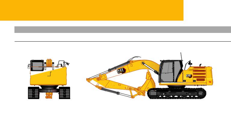
320
Hydraulic Excavator
Technical Specifications
Configurations and features may vary by region. Please consult your Cat® dealer for availability in your area.
Table of Contents
|
Specifications . . . . . . . . . . . . . . . . |
. . . . . . . . . . . . . . . . . . . . . . . . . . . . . . |
. 2 |
||
|
Engine . . . . . . . . . . . . . . . . . . . . . . . . . . . . . . . . . . . . . . . . . . . . . . . . |
. . . . . . . .2 |
Major Component Weights . . . . . . . . . . . . . . . . . . . . . . . . . . . . . . . . . . . |
. . .3 |
|
|
Swing Mechanism . . . . . . . . . . . . . . . . . . . . . . . . . . . . . . |
. . . . . . 2. . . . |
.Dimensions. . . . . . . . . . . . . . . . . . . . . . . . . . . . . . . . . . . . . . . . . . . . . . . . . . . . . |
. . .4 |
|
|
Weights . . . . . . . . . . . . . . . . . . . . . . . . . . . . . . . . . . . . . . . . . . . . . . . |
. . . . . . . .2 |
Working Ranges . . . . . . . . . . . . . . . . . . . . . . . . . . . . . . . . . . . . . |
. . .5. . . . . . . |
|
|
Track . . . . . . . . . . . . . . . . . . . . . . . . . . . . . . . . . . . . . . . . . . . . . . . |
. . . . . . . 2. . . |
Reach Boom Lift Capacities – Counterweight: 4..2 mt (9,300 lb) . . . |
. . .7. |
|
|
Drive . . . . . . . . . . . . . . . . . . . . . . . . . . . . . . . . . . . . . . . |
. . . . . . 2. . . . . |
HD. . Reach. . . . . Boom Lift Capacities – Counterweight: 4..7 mt (10,400 lb) |
. . .8 |
|
|
Hydraulic System . . . . . . . . . . . . . . . . . . . . . . . . . . . . . . . |
. . . . . .2. . . . |
Super. . . . . Long Reach Boom Lift Capacities – |
||
|
Service Refill Capacities |
2 |
Counterweight: 4..7 mt (10,400 lb) . . . . . . . . . . . . . . . . . . . . . . . . |
. . . 9. . . |
|
|
Bucket Specifications and Compatibility |
11 |
|||
|
Standards |
2 |
|||
|
Attachments Offering Guide |
13 |
|||
|
Sound Performance |
2 |
|||
|
Thumb Specifications |
16 |
|||
|
Operating Weight and Ground Pressure |
3 |
|||
|
Standard and Optional Equipment . . . . . . . . |
. . . . . . . . . . . . . . . . . . . . . . . . . . . . . |
. 17 |
||
|
Dealer Installed Kit and Attachments . . . . . . |
. . . . . . . . . . . . . . . . . . . . . . . . . . . . . . |
20 |

320 Hydraulic Excavator Specifications
Engine
|
Engine Model |
Cat® C4.4 |
|
|
Net Power (ISO 9249:2007) |
128 kW |
172 hp |
|
Engine Power (ISO 14396:2002) |
129 kW |
174 hp |
|
Bore |
105 mm |
4 in |
|
Stroke |
127 mm |
5 in |
|
Displacement |
4.4 L |
269 in3 |
•The 320 meets U.S. EPA Tier 4 Final emission standards.
•Recommended for use up to 4500 m (14,764 ft) altitude with engine power derate above 3000 m (9,842.5 ft).
•Net power is tested per ISO 14396:2002. Standards in effect at the time of manufacture.
•Net power available at the flywheel when engine is equipped with fan, air cleaner, aftertreatment, and alternator with engine speed at 2,200 rpm.
•Rated speed at 2,200 rpm.
Swing Mechanism
|
Swing Speed |
11.30 rpm |
|
|
Maximum Swing Torque |
82 kN·m |
60,300 lbf-ft |
Weights
|
Operating Weight |
22 500 kg |
49,600 lb |
•Reach boom, R2.9 (9’6″) stick, HD 1.19 m3 (1.56 yd3) bucket
790 mm (31 in) triple grouser shoes, 4.2 t (10.400 lb) counterweight.
Track
|
Standard Track Shoe Width |
790 mm |
31 in |
|
Number of Shoes (each side) |
49 |
|
|
Number of Track Rollers (each side) |
8 |
|
|
Number of Carrier Rollers (each side) |
2 |
Drive
|
Gradeability |
35°/70% |
|
|
Maximum Travel Speed |
5.7 km/h |
3.5 mph |
|
Maximum Drawbar Pull – |
205 kN |
45,996 lbf |
|
Long Undercarriage |
Hydraulic System
|
Main System – Maximum Flow – |
429 L/min |
113 gal/min |
|
Implement |
(214.5 × |
(56.5 × |
|
2 pumps) |
2 pumps) |
|
|
Maximum Pressure – Equipment – |
35 000 kPa |
5,075 psi |
|
Normal |
||
|
Maximum Pressure – Equipment – |
38 000 kPa |
5,510 psi |
|
Lift Mode |
||
|
Maximum Pressure – Travel |
34 300 kPa |
4,974 psi |
|
Maximum Pressure – Swing |
27 500 kPa |
3,998 psi |
|
Boom Cylinder – Bore |
120 mm |
4.7 in |
|
Boom Cylinder – Stroke |
1260 mm |
49.6 in |
|
Stick Cylinder – Bore |
140 mm |
5.5 in |
|
Stick Cylinder – Stroke |
1504 mm |
59.2 in |
|
Bucket Cylinder – Bore |
120 mm |
4.7 in |
|
Bucket Cylinder – Stroke |
1104 mm |
43.5 in |
Service Refill Capacities
|
Fuel Tank Capacity |
345 L |
86.6 gal |
|
Cooling System |
25 L |
6.6 gal |
|
Engine Oil |
15 L |
4.0 gal |
|
Swing Drive (each) |
12 L |
3.2 gal |
|
Final Drive (each) |
5 L |
1.3 gal |
|
Hydraulic System (including tank) |
234 L |
61.8 gal |
|
Hydraulic Tank |
115 L |
30.4 gal |
|
DEF Tank |
39 L |
10.3 gal |
Standards
|
Brakes |
ISO 10265: 2008 |
|
Cab/ROPS |
ISO 12117-2: 2008 |
|
FOGS (optional) |
ISO 10262-2: 1998 |
Sound Performance
|
ISO 6395:2008 |
(external) |
99 dB(A) |
|
ISO 6396:2008 |
ISO 6396 (inside cab) |
70 dB(A) |
•Hearing protection may be needed when operating with an open operator station and cab (when not properly maintained or doors/ windows open) for extended periods or in a noisy environment.
2

320 Hydraulic Excavator Specifications
Operating Weight and Ground Pressure
|
790 mm (31 in) |
|||||
|
Triple Grouser Shoes |
|||||
|
Weight |
Ground Pressure |
||||
|
4.2 mt (9,300 lb) Counterweight + Base Machine |
|||||
|
Reach Boom + R2.9 (9’6″) Stick + 1.19 m3 (1.56 yd3) HD Bucket |
22 500 kg |
49,600 lb |
35.5 kPa |
5.2 psi |
|
|
4.7 mt (10,400 lb) Counterweight + Base Machine |
|||||
|
HD Reach Boom + HD R2.9 (9’6″) Stick + 1.19 m3 (1.56 yd3) HD Bucket |
24 300 kg |
53,600 lb |
38.4 kPa |
5.6 psi |
|
|
SLR Boom + SLR Stick + 0.53 m3 (0.69 yd3) GD Bucket |
23 900 kg |
52,700 lb |
37.8 kPa |
5.5 psi |
All operating weights include a 90% fuel tank with 75 kg (165 lb) operator..
Major Component Weights
|
kg |
lb |
||
|
Base Machine (with 4.2 mt [9,300 lb] counterweight, semi-HD swing frame, standard base frame with |
14 800 |
32,600 |
|
|
HD track rollers and standard carrier rollers for long undercarriage, without boom cylinder – does not |
|||
|
include 90% fuel and 75 kg [165 lb] operator) |
|||
|
Base Machine (with 4.7 mt [10,400 lb] counterweight, HD swing frame, HD base frame with SD track rollers |
16 000 |
35,300 |
|
|
and SD carrier rollers for Long undercarriage without boom cylinder – does not include 90% fuel and 75 kg |
|||
|
[165 lb] operator) |
|||
|
Track Shoes: |
|||
|
790 mm (31 in) Width, 10 mm (0.39 in) Thick Triple Grouser Track Shoes for Long Undercarriage |
3370 |
7,400 |
|
|
with Step Extension for ISO 2867:2011 |
|||
|
Two Boom Cylinders |
340 |
750 |
|
|
Weight of 90% Fuel Tank and 75 kg (165 lb) Operator |
310 |
680 |
|
|
Counterweights: |
|||
|
4.2 mt Counterweight |
4200 |
9,300 |
|
|
4.7 mt Counterweight |
4700 |
10,400 |
|
|
Swing Frame: |
|||
|
Semi-HD Swing Frame |
1910 |
4,210 |
|
|
Undercarriage: |
|||
|
Standard Base Frame with HD Track Rollers and Standard Carrier Rollers for Long Undercarriage |
4390 |
9,700 |
|
|
Booms (including lines, pins, stick cylinder): |
|||
|
Reach Boom (5.7 m/18’8″) |
1710 |
3,800 |
|
|
HD Reach Boom (5.7 m/18’8″) |
2010 |
4,400 |
|
|
Super Long Reach Boom (8.85 m/29’0″) |
2170 |
4,800 |
|
|
Sticks (including lines, pins, bucket cylinder, bucket linkage): |
|||
|
Reach Stick (R2.9B1/9’6″) |
990 |
2,200 |
|
|
HD Thumb Ready Reach Stick (R2.9B1/9’6″) |
1300 |
2,900 |
|
|
Super Long Reach Stick (6.28A/20’7″) |
1340 |
3,000 |
|
|
Buckets (without linkage): |
|||
|
1.19 m3 (1.56 yd3) HD |
960 |
2,100 |
|
|
0.57 m3 (0.75 yd3) Ditch Cleaning |
390 |
900 |
|
|
Quick Coupler: |
|||
|
Pin Grabber QC |
390 |
900 |
3
320 Hydraulic Excavator Specifications
Dimensions
All dimensions are approximate and may vary depending on bucket selection..
|
3 |
4 |
|
|
1 |
||
|
6 |
5 |
|
|
9 |
8 |
|
|
10 |
7 |
|
|
2 |
|
Boom Options |
HD Reach/Reach Boom |
SLR Boom |
||||
|
5.7 m (18’8″) |
8.85 m (29’0″) |
|||||
|
Stick Options |
HD TR Reach/Reach Stick |
SLR Stick |
||||
|
R2.9B1 (9’6″) |
6.28A (20’7″) |
|||||
|
1 |
Machine Height: |
|||||
|
Top of Cab Height |
2960 mm |
9’9″ |
2960 mm |
9’9″ |
||
|
Top of FOGS Height |
3100 mm |
10’2″ |
3100 mm |
10’2″ |
||
|
Handrails Height |
2950 mm |
9’8″ |
2950 mm |
9’8″ |
||
|
With Boom/Stick/Bucket Installed |
3160 mm |
10’4″ |
3190 mm |
10’6″ |
||
|
With Boom/Stick Installed |
2910 mm |
9’7″ |
3070 mm |
10’1″ |
||
|
With Boom Installed |
2480 mm |
8’2″ |
2650 mm |
8’8″ |
||
|
2 |
Machine Length: |
|||||
|
With Boom/Stick/Bucket Installed |
9530 mm |
31’3″ |
12 750 mm |
41’10» |
||
|
With Boom/Stick Installed |
9500 mm |
31’2″ |
12 760 mm |
41’10» |
||
|
With Boom Installed |
8450 mm |
27’9″ |
8920 mm |
29’3″ |
||
|
3 |
Upperframe Width without Walkways |
2780 mm |
9’1″ |
2780 mm |
9’1″ |
|
|
4 |
Tail Swing Radius |
2830 mm |
9’3″ |
2830 mm |
9’3″ |
|
|
5 |
Counterweight Clearance |
1050 mm |
3’5″ |
1050 mm |
3’5″ |
|
|
6 |
Ground Clearance |
470 mm |
1’7″ |
470 mm |
1’7″ |
|
|
7 |
Track Length |
4450 mm |
14’7″ |
4450 mm |
14’7″ |
|
|
8 |
Length to Center of Rollers |
3650 mm |
12’0″ |
3650 mm |
12’0″ |
|
|
9 |
Track Gauge |
2380 mm |
7’9″ |
2380 mm |
7’9″ |
|
|
10 |
Undercarriage Width: |
|||||
|
790 mm (31 in) Shoes |
3170 mm |
10’5″ |
3170 mm |
10’5″ |
||
|
Bucket Type |
HD |
Ditch Cleaning (DC) |
||||
|
Bucket Capacity |
1.14 m3 |
1.50 yd3 |
0.57 m3 |
0.75 yd3 |
||
|
Bucket Tip Radius |
1470 mm |
4’10» |
1070 mm |
3’6″ |
4
320 Hydraulic Excavator Specifications
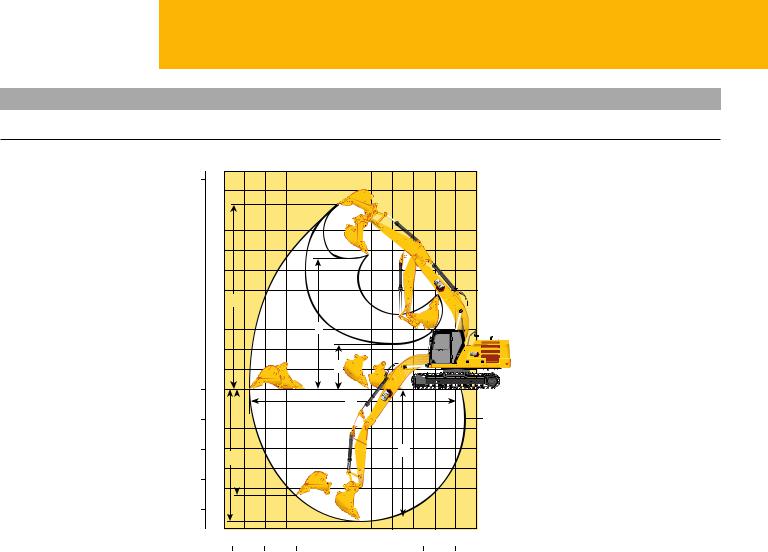
Working Ranges
All dimensions are approximate and may vary depending on bucket selection..
|
ft |
m |
|||
|
35 |
11 |
|||
|
10 |
||||
|
30 |
9 |
|||
|
25 |
8 |
|||
|
7 |
||||
|
20 |
6 |
|||
|
15 |
5 |
3 |
||
|
4 |
||||
|
10 |
3 |
4 |
||
|
5 |
2 |
|||
|
1 |
5 |
|||
|
0 |
0 |
|||
|
1 |
2 |
|||
|
5 |
R2.9B1 (9’6″) |
|||
|
2 |
||||
|
10 |
3 |
7 |
6 |
|
|
1 |
||||
|
4 |
||||
|
15 |
5 |
|||
|
20 |
6 |
|||
|
7 |
|
11 |
10 |
9 |
8 |
7 |
6 |
5 |
4 |
3 |
2 |
1 |
0 |
–1 |
m |
||
|
35 |
30 |
25 |
20 |
15 |
10 |
5 |
0 |
ft |
|||||||
|
Boom Option |
HD Reach/Reach Boom |
||||||||||||||
|
5.7 m (18’8″) |
|||||||||||||||
|
Stick Option |
HD TR Reach/Reach Stick |
||||||||||||||
|
R2.9B1 (9’6″) |
|||||||||||||||
|
1 |
Maximum Digging Depth |
6620 mm |
21’9″ |
||||||||||||
|
2 |
Maximum Reach at Ground Line |
9760 mm |
32’0″ |
||||||||||||
|
3 |
Maximum Cutting Height |
9330 mm |
30’7″ |
||||||||||||
|
4 |
Maximum Loading Height |
6590 mm |
21’7″ |
||||||||||||
|
5 |
Minimum Loading Height |
2270 mm |
7’5″ |
||||||||||||
|
6 |
Maximum Depth Cut for 2440 mm (8’0″) Level Bottom |
6440 mm |
21’2″ |
||||||||||||
|
7 |
Maximum Vertical Wall Digging Depth |
5360 mm |
17’7″ |
||||||||||||
|
Bucket Digging Force (ISO) |
163 kN |
36,711 lbf |
|||||||||||||
|
Stick Digging Force (ISO) |
109 kN |
24,486 lbf |
|||||||||||||
|
Bucket Type |
HD |
||||||||||||||
|
Bucket Capacity |
1.14 m3 |
1.50 yd3 |
|||||||||||||
|
Bucket Tip Radius |
1470 mm |
4’10» |
5

320 Hydraulic Excavator Specifications
Working Ranges
All dimensions are approximate and may vary depending on bucket selection..
|
ft |
m |
||||||||||||||||||||||||
|
45 |
14 |
||||||||||||||||||||||||
|
13 |
|||||||||||||||||||||||||
|
40 |
12 |
||||||||||||||||||||||||
|
35 |
11 |
||||||||||||||||||||||||
|
10 |
|||||||||||||||||||||||||
|
30 |
9 |
||||||||||||||||||||||||
|
25 |
8 |
||||||||||||||||||||||||
|
7 |
3 |
||||||||||||||||||||||||
|
20 |
6 |
4 |
|||||||||||||||||||||||
|
5 |
|||||||||||||||||||||||||
|
15 |
|||||||||||||||||||||||||
|
4 |
|||||||||||||||||||||||||
|
10 |
3 |
||||||||||||||||||||||||
|
5 |
2 |
||||||||||||||||||||||||
|
1 |
|||||||||||||||||||||||||
|
0 |
0 |
||||||||||||||||||||||||
|
5 |
1 |
2 |
|||||||||||||||||||||||
|
2 |
|||||||||||||||||||||||||
|
10 |
3 |
||||||||||||||||||||||||
|
15 |
4 |
6.28A (20’7″) |
|||||||||||||||||||||||
|
5 |
|||||||||||||||||||||||||
|
1 |
7 |
6 |
|||||||||||||||||||||||
|
20 |
6 |
||||||||||||||||||||||||
|
25 |
7 |
||||||||||||||||||||||||
|
8 |
|||||||||||||||||||||||||
|
30 |
9 |
||||||||||||||||||||||||
|
35 |
10 |
||||||||||||||||||||||||
|
11 |
|||||||||||||||||||||||||
|
40 |
12 |
19 |
18 |
17 |
16 |
15 |
14 |
13 |
12 |
11 |
10 |
9 |
8 |
7 |
6 |
5 |
4 |
3 |
2 |
1 |
0 |
–1 |
–2 |
–3 |
m |
|
20 |
|||||||||||||||||||||||||
|
65 |
60 |
55 |
50 |
45 |
40 |
35 |
30 |
25 |
20 |
15 |
10 |
5 |
0 |
–5 |
ft |
|
Boom Option |
SLR Boom |
||
|
8.85 m (29’0″) |
|||
|
Stick Option |
SLR Stick |
||
|
6.28A (20’7″) |
|||
|
1 |
Maximum Digging Depth |
11 540 mm |
37’10» |
|
2 |
Maximum Reach at Ground Line |
15 570 mm |
51’1″ |
|
3 |
Maximum Cutting Height |
13 540 mm |
44’5″ |
|
4 |
Maximum Loading Height |
11 440 mm |
37’6″ |
|
5 |
Minimum Loading Height |
2240 mm |
7’4″ |
|
6 |
Maximum Depth Cut for 2440 mm (8’0″) Level Bottom |
11 440 mm |
37’6″ |
|
7 |
Maximum Vertical Wall Digging Depth |
11 020 mm |
36’2″ |
|
Bucket Digging Force (ISO) |
62 kN |
13,841 lbf |
|
|
Stick Digging Force (ISO) |
49 kN |
10,966 lbf |
|
|
Bucket Type |
Ditch Cleaning (DC) |
||
|
Bucket Capacity |
0.57 m3 |
0.75 yd3 |
|
|
Bucket Tip Radius |
1070 mm |
3’6″ |
6
 Loading…
- 0
- 0
- July 2019
- Bookmark
Embed- Share
Download
This document was uploaded by user and they confirmed that they have the permission to share
it. If you are author or own the copyright of this book, please report to us by using this DMCA
report form. Report DMCA
Overview
Download & View Cat 320d Manual as PDF for free.
More details
- Words: 1
- Pages: 1,023

Download Complete Caterpillar Cat 320D , 320DL Excavator Parts Manual
FAL1-Up (Machine)
KGF1-Up (Machine)
GDC1-Up (Engine)
This Factory Parts Manual offers all the parts information about Caterpillar Cat 320D , 320DL Excavator. The information on this manual covered everything you need to know when you want to repair or service Caterpillar Cat 320D , 320DL Excavator.
Click Here To Preview Online
Manual Contents:
INDEX
ENGINE ARRANGEMENT
LUBRICATION SYSTEM
COOLING SYSTEM
AIR INLET AND EXHAUST SYSTEM
FUEL SYSTEM
ELECTRICAL AND STARTING SYSTEM
POWER TRAIN
FRAME AND BODY
HYDRAULIC SYSTEM 1
HYDRAULIC SYSTEM 2
OPERATOR STATION
IMPLEMENTS
SERVICE EQUIPMENT AND SUPPLIES
PART NUMBER INDEX
This manual can be used by anyone from a first time owner/amateur to a professional technician.Even the most novice mechanic can also easily follow the step-by-step guides which are made simple by the illustrations and drawings.Keep this manual handy and use it often. Performing routine, preventive maintenance will save you time & money by helping to prevent premature failure and unnecessary repairs.
You will receive a download link immediately after your payment is completed. So please make sure your email address is correct.
File Format: PDF
Compatible: All Versions of Windows & Mac
Language: English
Introduction
This manual contains information on the troubleshooting procedures of the electronic control and hydraulic systems in the 320 and 320 L Excavator. This manual is divided into the following three main sections:
- 1. Electronic System Testing And Adjusting
- 2. Checking Procedures
- 3. Hydraulic System Testing And Adjusting
NOTE: As a general rule, if there is a doubt as to the cause of a problem, the electronic system should be checked first.
Reference: For information on Systems Operation of the above, make reference to: «Systems Operation, Electronic System», Form SENR5463 and/or «Systems Operation, Hydraulic System», Form SENR5464.
For troubleshooting the engine components, refer to: «Systems Operation, Testing And Adjusting, Basic Engine Components 3306 Engine», Form SENR5546.
Checking Procedures
In each checking procedure, it is assumed that the engine operation is normal unless otherwise specified.
Electronic Control System
The monitor and electronic controller are the main components of the electronic control system. The monitor and electronic controller have a self diagnostic function. Self diagnostic checks of the monitor, electronic controller, and the communication line between them are the first steps when troubleshooting the problem(s) in the electronic system.
Action alarm indicators on the monitor panel, alert an operator to a problem in the electronic system. The controller service program «Data Mode» can also be used to identify the problems (see the section of this module «Data Mode»). If the service program is activated during machine operation, problem(s) that are monitored by the monitoring system are indicated on the character display. If the service program is activated when the machine operation is stopped, all existing problems and past problems (problems that have not been corrected) are indicated on the character display. To activate the controller service program «Data Mode», refer to the «Data Mode» section in this module.
Operational Tests
If the electronic power unit control system display indicates it is operating correctly, then do operational tests. Operate the machine, following the procedures described in the section «Hydraulic System Testing And Adjusting». Compare the results of the operational tests with specifications to determine the extent of the trouble. In operational tests, it is important to determine whether or not enough hydraulic force or implement speed is a problem that extends over the entire machine or with only a specific operation.
If there are any faults in the circuits between the main or pilot pumps and the control valves, the overall performance of the machine will decrease. This type of problem in the hydraulic system is not detected by the self diagnostic functions of the electronic control system described above (no action alarm indication on character display.). To detect such a problem, it is necessary to check the flow characteristics of the pumps, the main relief pressure, pilot pressure, etc.
Service Program
Electronic Monitor Panel

(1) Engine coolant temperature gauge. (2) Fuel gauge. (3) Action lamp. (4) Character display. (5) Monitor panel. (6) Hydraulic oil temperature gauge. (7) Work mode selector switch. (8) Air heater indicator. (9) Charge alarm indicator. (10) Engine coolant temperature alarm indicator. (11) Hydraulic oil temperature alarm indicator. (12) Engine oil pressure alarm indicator. (13) Controller alarm indicator. (14) Monitor alarm indicator. (15) Work mode boom priority indicator. (16) Work mode swing priority indicator. (17) Power mode selector switch. (18) Power mode III indicator. (19) Power mode II indicator. (20) Power mode I indicator. (21) Work mode fine control indicator. (22) Light switch. (23) Light 1 indicator. (24) Light 2 indicator. (25) Wiper 2 indicator. (26) Travel speed HIGH (rabbit) indicator. (27) Travel speed LOW (tortoise) indicator. (28) Travel speed control switch. (29) AEC indicator. (30) Switch panel. (31) AEC switch. (32) Wiper 1 indicator. (33) Washer indicator. (34) Washer switch. (35) Wiper switch. (36) Alarm cancel switch. (37) Service switch. (38) Alarm cancel indicator.
Introduction
The electronic Monitor Panel activates and displays the output received from the Electronic Controller. The Electronic Controller Service Program is divided into two program modes. Each program mode has a particular function as follows:
- 1. Data Mode;
This program mode contains eight function modes and provides the necessary information for the mechanic to determine the machine condition.
- 2. Calibration Mode;
This program mode contains ten function modes and provides information used to adjust and confirm system/component functions after replacement of electronic control system components. This program level is also used to help the mechanic troubleshoot machine problems.
To activate the service program mode functions, use the control switches provided on the electronic monitor panel.
NOTE: Unexpected character display readings due to random operation of switches should be disregarded.
To select a desired function mode, first start a proper service program mode (see the section «Data Mode Start-up» and/or «Calibration Mode Start-up»). Next, operate the control switch(es) as specified, until the desired information is indicated on the character display.
When the selected service program function is no longer needed, use the proper procedure (see the section «Data Mode Stop Procedure» and/or «Calibration Mode Stop Procedure») to cancel.
Data Mode
NOTE: Activation of service program «Data Mode» does not affect any machine controls and operations except for the following:
The LED indicators for power mode switch, travel speed control switch, light switch, and wiper switch come ON only in flashing mode during activation of service program «Data Mode».
The Data Mode contains the following function modes which provide eight categories of information.
- 1. Power shift pressure.
- 2. Engine speed.
- 3. Engine coolant temperature.
- 4. Hydraulic oil temperature.
- 5. A/D (Analog/Digital) conversion.
- 6. Real time error.
- 7. Digital input.
- 8. Output control display.
Data Mode Start-up

Electronic Monitor Panel (Data Mode Start-up)
(4) Character display. (17) Power mode selector switch. (18) Power mode III indicator. (36) Alarm cancel switch. (38) Alarm cancel indicator.
NOTE: To access and view the eight available functions in the «Data Mode», the engine can either be running or shut down. If the engine is running the eight Data Mode functions can be viewed as operating values. If the engine is not running the starter switch must be in the «ON» position.
1. Depress and hold alarm cancel switch (36) until alarm cancel indicator (38) starts flashing.
2. While alarm cancel switch (36) is depressed, push power mode selector switch (17) until power mode III indicator (18) begins to flash. Release alarm cancel switch (36) and power mode selector switch (17).
3. The service program «Data Mode» is now activated and character display (4) will display the first function mode (power shift pressure) value.
NOTE: If switch (17) is held too long, the character display will sequence through the eight available function modes in the «Data Mode» program.
Data Mode Function Selection

Electronic Monitor Panel (Data Mode Function Selection)
(4) Character display. (17) Power mode selector switch. (18) Power mode III indicator. (36) Alert cancel switch.
1. Repeatedly push first alarm cancel switch (36) and then power mode switch (17) until the desired function mode is displayed on character display (4).
2. Each time both switches are pushed, the function mode changes in an increasing number sequence of the eight function modes in a repetitious manner.
3. At the same time that the function mode character is displayed the corresponding switch indicator comes on. To determine the function mode selected, look for the switch indicator which is flashing.
NOTE: If alarm cancel switch (36) is depressed for more than 2 seconds the Data Mode stops and character display (4) displays the engine speed dial position.
NOTE: Accessing the «Data Mode Functions» must be performed in the sequence shown in the following chart.
Each of the eight Data Mode functions has a designated indicator light. The following chart shows the eight Data Mode functions and their designated indicator lights:

Power Shift Pressure

Electronic Monitor Panel (Power Shift Pressure)
(4) Character display. (17) Power mode selector switch. (18) Power mode III indicator. (36) Alarm cancel switch.
When this function mode is selected, power mode III indicator (18) flashes. The character display (4) displays «P» in the first position and actual power shift pressure in the second and third positions. The unit of power shift pressure is in kgf/cm2. 1 kgf/cm2 is approximately the same as 100 kPa (14 psi).
Engine Speed

Electronic Monitor Panel (Engine Speed)
(4) Character display. (19) Power mode II indicator.
When this function mode is selected, power mode II indicator (19) flashes. Character display (4) will display the engine speed in rpm, regardless of the machine load. Multiply the rpm values in character display (4) by 10 to determine actual rpm.
Engine Coolant Temperature

Electronic Monitor Panel (Engine Coolant Temperature)
(4) Character display. (20) Power mode I indicator.
When this function mode is selected, power mode I indicator (20) flashes. Character display (4) displays the engine coolant temperature within a range of 14°C to 127°C (57°F to 260°F). The engine coolant temperature units are displayed in 1°C (1.8°F) increments. If the character display reading is below 0°C, the first position on the character display reads «-«.
NOTE: Character display (4) displays the engine coolant temperature in degrees Celsius.
Hydraulic Oil Temperature

Electronic Monitor Panel (Hydraulic Oil Temperature)
(4) Character display. (23) Light 1 indicator.
When this function mode is selected, light 1 indicator (23) flashes. Character display (4) displays the hydraulic oil temperature within a range of 14°C to 127°C (57.2°F to 260.6°F). The hydraulic oil temperature units are displayed in 1°C (1.8°F) increments.
NOTE: Character display (4) displays the hydraulic oil temperature in degrees Celsius.
A/D (Analog/Digital) Conversion

Electronic Monitor Panel (A/D Conversion)
(4) Character display. (24) Light 2 indicator.
When the analog/digital conversion function mode is selected, light 2 indicator (24) flashes. Character display (4) displays the analog information for eight machine functions. A conversion chart is needed to understand the digital information indicated. Description of the eight machine functions omitted since this information is not needed for service or diagnosis.
Real Time Error Codes

Electronic Monitor Panel (Real Time Error Codes)
(4) Character display. (26) Travel speed HIGH (rabbit) indicator.
When this mode is selected, travel speed HIGH (rabbit) indicator (26) flashes. Character display (4) displays the codes for problems that have occurred. They are displayed in an increasing number sequence according to «Problem List» shown below, in a repetitious manner. A character display code remains displayed for 2 seconds with an interval of 1 second between codes.
NOTE: A display code of [E00] indicates that there are no system errors.

NOTE: Go to the appropriate «Electronic Sequence Chart» to troubleshoot the problem of [E33] in accordance with the following:

Digital Input

Electronic Monitor Panel (Digital Input)
(4) Character display. (7) Work mode switch. (17) Power mode selector switch. (27) Travel speed LOW (tortoise) indicator. (36) Alarm cancel switch.
When this mode is selected, travel speed LOW (tortoise) indicator (27) flashes. This mode displays 21 types of information on character display (4).
1. Depress and hold alarm cancel switch (36) and then depress power mode switch (17) until travel speed LOW (tortoise) indicator (27) flashes. Release alarm cancel switch (36) and power mode switch (17).
2. Character display (4) will display [0 9]. The «0» indicates that this is the first of 21 «ports» or additional types of information. The » 9″ indicates the wiring harness code for the 320 and 320 L Excavators with 3066 engine.
3. To sequence through the 21 «ports», first depress and hold alarm cancel switch (36) and then work mode switch (7) until the character display reads the desired «port».
NOTE: This mode is capable of providing a total of 21 types of information. Eight of the 21 «ports» (additional types of information) are spares.
The following chart gives a listing of the 21 «ports» and their components:

NOTE: Ports «0» and «1» give no indication of «[ O n] or [ o F] on the character display.
Typical Examples:
[0 9]: Indicates the machine model of «320» or «320 L» excavator with 3066 engine. If a different code appears in the second and third positions, check the circuit for good grounding.
[1 1]: Engine speed dial is in position «1».
[110]: Engine speed dial is in position «10».
[1Er]: There is a problem in engine speed dial or circuit between speed dial and controller. (Er:error)
[2On]: Travel pressure switch is ON.
[2oF]: Travel pressure switch is OFF.
NOTE: To check the travel pressure switch, activate the travel control with the pressure switch in ON position. If the character display does not read [2On], it is an indication of a possible problem in the travel pressure switch and/or its circuit.
Output Control Display

Electronic Monitor Panel (Output Control Display)
(4) Character display. (32) Wiper 1 indicator.
When this function mode is selected, wiper 1 indicator (32) flashes. Character display (4) displays the code that represents current pump output. The initial code displayed will be [L00] for a normal pump output control. The character display code remains ON for 2 seconds with an interval of 0.5 seconds between codes.
Typical Examples:
[L00]: Output control is normal.
[L A]: Pump output control when governor actuator feedback sensor is abnormal.
[L b]: Pump control under too low hydraulic oil temperature.
NOTE: [L b] is displayed only when one of the controls is activated.
NOTE: During «Output Control Display» function, the AEC system and one touch low idle do not activate. The engine speed dial switch controls the engine speed only under a no load condition.
Reference: For more information on the pump output control, refer to module, «Systems Operation, Electronic System», Form SENR5463.
Data Mode Stop Procedure

Electronic Monitor Panel (Stop Procedure)
(4) Character display. (36) Alarm cancel switch.
Use either of the following two methods.
1. Turn the engine start switch to the OFF position.
2. Keep alarm cancel switch (36) depressed at least 2 seconds until character display (4) displays the engine speed dial position.
Calibration Mode
NOTE: The procedures for each function in «Calibration Mode» are independent of each other. The engine does not need to be running for all the functions listed in the following chart. The following chart lists the functions in «Calibration Mode» and whether the engine must be running for each of the functions:

Calibration Mode Start-up

Electronic Monitor Panel (Calibration Mode Start-up)
(1) Engine coolant temperature gauge. (2) Fuel gauge. (3) Action lamp. (4) Character display. (6) Hydraulic oil temperature gauge. (8) Air heater indicator. (9) Charge alarm indicator. (10) Engine coolant temperature alarm indicator. (11) Hydraulic oil temperature alarm indicator. (12) Engine oil pressure alarm indicator. (13) Controller alarm indicator. (14) Monitor alarm indicator. (37) Service switch.
Show/hide table
|
|
| NOTICE |
|---|
|
Before to starting the Calibration Mode, the engine speed dial switch should be set at dial position «1» and the engine start switch must be in the OFF position. |
|
|
1. Depress service switch (37) and start the engine. As shown in the chart above, the engine does not need to be started to obtain information for certain functions in the «Calibration Mode».
2. Continue to depress service switch (37) until action lamp (3) comes ON and character display (4) displays [20H]. All the alarm indicators except character display (4) will turn OFF.
3. The «Calibration Mode» is now accessed and character display (4) displays the first of the 10 functions (machine and engine model numbers) as shown in the chart above. Action lamp (3) remains ON during all calibration function modes.
NOTE: Activation of the «Calibration Mode» overrides the function of engine coolant temperature gauge (1), fuel gauge (2), action lamp (3), hydraulic oil temperature gauge (6), air heater indicator (8), charge alarm indicator (9), engine coolant temperature alarm indicator (10), hydraulic oil temperature alarm indicator (11), engine oil pressure alarm indicator (12), controller alarm indicator (13), and monitor alarm indicator (14).
Calibration Mode Function Selection

Electronic Monitor Panel (Function Selection)
(3) Action lamp. (4) Character display. (17) Power mode selector switch. (22) Light switch. (28) Travel speed control switch. (31) AEC switch. (35) Wiper switch.
Power mode selector switch (17), light switch (22), AEC switch (31), wiper switch (35), and travel speed control switch (28) are pushed each time to obtain one of ten function modes.
Machine And Engine Model

Electronic Monitor Panel (Machine And Engine Model)
(4) Character display. (17) Power mode selector switch. (18) Power Mode III indicator.
1. Start «Calibration Mode». See the section, «Calibration Mode Start-up».
Upon accessing the «Calibration Mode», the machine and engine model is the first function accessed. To obtain this function again after viewing or accessing any of the other functions, depress power mode selector switch (17) until power Mode III indicator (18) comes ON.
2. Character display (4) displays [20H] for a «320» or «320 L» excavator equipped with a 3066 engine. The first and second positions of character display (4) shows the code for the model excavator. The third position of character display (4) shows the code for the engine model.
3. Stop «Calibration Mode» (unless another function selection is desired). See the section, «Calibration Mode Stop Procedure».
NOTE: Activation of the «Calibration Mode» overrides the AEC function and keeps the power shift pressure constant at a pressure level equivalent to a no-load condition. The engine speed dial switch works normally.
Controller/Monitor Software Version

Electronic Monitor Panel (Controller/Monitor Software Version)
(4) Character display. (17) Power mode selector switch. (19) Power Mode II indicator. (31) AEC switch.
1. Start «Calibration Mode». See the section, «Calibration Mode Start-up».
2. Depress power mode selector switch (17) until power Mode II indicator (19) comes ON.
3. Character display (4) displays [17C] for example. The «17» in the character display represents a two digit numeral particular to the software for each machine mode. The «C» represents the controller.
4. To determine the software version for the monitor depress AEC switch (31). Character display (4) displays [20P] for example. The «20» in the character display represents a two digit numeral particular to the software for each machine mode. The «P» represents the software version.
NOTE: Each time AEC switch (31) is depressed, the character display will alternate between the two software codes [17C] and [20P] for example.
5. Stop «Calibration Mode» (unless another function selection is desired). See the section, «Calibration Mode Stop Procedure».
NOTE: Activation of the «Calibration Mode» overrides the AEC function and keeps the power shift pressure constant at a pressure level equivalent to a no-load condition. The engine speed dial switch works normally.
Error log

Electronic Monitor Panel (Error Log)
(4) Character display. (17) Power mode selector switch. (20) Power Mode I indicator. (28) Travel speed control switch. (31) AEC switch. (34) Washer switch.
1. Start «Calibration Mode». See the section, «Calibration Mode Start-up».
2. Depress power mode selector switch (17) until power Mode I indicator (20) comes ON.
3. Character display (4) displays [Hd ]. This display indicates that the list of stored error codes can be viewed. The controller has a continual self-diagnostic function during machine operation. The controller will store error codes if a fault is detected, even an intermittent fault. The list of error codes is stored in the error history on important systems until the memory is cleared.
4. The error codes are viewed on the character display either in ascending or descending order. Each time AEC switch (31) is depressed, the ascending sequential list of stored error codes are displayed as shown in the following example:
- [Hd ][F 6][F10][F40][F41][End]
5. Each time washer switch (34) is depressed, the descending sequential list of stored error codes are displayed as shown in the following example:
- [End][F41][F40][F10][F 6][Hd]]
NOTE: A «F» in the first position of character display (4) represents a stored error code (error history). An «E» in the first position of character display (4) represents a real time error code.
- * AEC switch (31)
- * Power mode selector switch (17)
- * Travel speed control switch (28)
6. To clear the error codes and error history, push and hold in sequence for approximately three seconds the following three buttons:
7. The error codes are cleared from the error history memory when character display (4) displays [CLr] and then returns to display [Hd ].
Reference: For a listing of error codes, see the section in this module «Data Mode, Real Time Errors Codes».
NOTE: Information about a problem is stored by this function mode until the correct clearing procedure is completed. Always clear the error history after the problem has been corrected.
NOTE: Activation of the error log mode overrides the function of the AEC system and keeps the power shift pressure constant at the no load pressure level. The engine speed dial works normally.
8. Stop «Calibration Mode» (unless another function selection is desired). See the section, «Calibration Mode Stop Procedure».
NOTE: The following error log codes are not displayed on the character display during activation of this calibration mode.
F1 to F5, F7, F9, F12, F15, F32, F34, F37, F38, F39, and F48.
NOTE: Activation of the «Calibration Mode» overrides the AEC function and keeps the power shift pressure constant at a pressure level equivalent to a no-load condition. The engine speed dial switch works normally.
Digital Output Test

Electronic Monitor Panel (Digital Output Test)
(4) Character display. (22) Light switch. (23) Light 1 indicator. (29) AEC indicator. (31) AEC switch. (33) Washer indicator. (34) Washer switch. (36) Alarm cancel switch.
1. Start «Calibration Mode». See the section, «Calibration Mode Start-up».
2. Depress light switch (22) until light 1 indicator (23) comes ON.
3. Character display (4) displays [0oF] which represents the first of 10 components that can be tested. There are 16 «ports» available of the electrical connections for various controller output components (similar to the «Digital Input» information accessed in «Data Mode»). Six of the «ports» are spares. The code in the first position of the character display represents the particular «port» of each component.
The «ports» and their components are shown in the following chart:

4. Each time AEC switch (31) is pushed, a different port code appears in character display (4) in an ascending order. Press washer switch (34) to view the ports in descending order.
5. Press alarm cancel switch (36) to turn the component for each port, either ON or OFF. Character display (4) displays as shown in the chart above as each port is turned ON or OFF. If an over current occurs at a component, the character display (4) displays [OEr].
6. Stop «Calibration Mode» (unless another function selection is desired). See the section, «Calibration Mode Stop Procedure».
NOTE: Activation of the «Calibration Mode» overrides the AEC function and keeps the power shift pressure constant at a pressure level equivalent to a no-load condition. The engine speed dial switch works normally.
Proportional Reducing Valve Sweep Test


Pilot Oil Manifold Compartment
(39) Connector.
1. Stop the engine and disconnect connector (39) from the proportional reducing valve.
2. Connect the test harness to connector (39).

Main Pump Compartment
(40) Power shift pressure tap.
3. Install a 4900 kPa (700 psi) pressure gauge at power shift pressure tap (40).
4. The pump backup switch must be in the «AUT» position.
5. Start «Calibration Mode». See the section, «Calibration Mode Start-up».
NOTE: The engine must be running to obtain accurate information for this test.
6. Warm the hydraulic oil to normal operating temperature.
7. Run the engine at maximum no-load rpm.
8. All controls must be in the NEUTRAL position.

Electronic Monitor Panel (Proportional Reducing Valve Sweep Test)
(4) Character display. (22) Light switch. (24) Light 2 indicator.
9. Start the «Proportional Reducing Valve Sweep Test» as follows:
a. Depress light switch (22) until light 2 indicator (24) comes ON.
b. The left column of character display (4) displays the letter «P». The «P» in the first column indicates that the proportional reducing valve is being tested.
NOTE: The purpose of this function is to check whether the proportional reducing valve is activating with a current signal from the controller. When this function is selected, the second and third column in character display (4) changes in an ascending number sequence from of 0 to 32. One cycle range from 0 to 32 takes about five seconds. The character display (4) sequences form [P 0] to [P32].
10. As the «PRV Sweep Test» is being performed, monitor the multimeter and the 4900 kPa (700 psi) pressure gauge.
The multimeter reading changes within a range of 0.16 to 0.63 amps in approximately five seconds. The pressure gauge at power shift pressure tap (40) simultaneously ranges from 0 to 3150 kPa (0 to 455 psi).
NOTE: During the «PRV Sweep Test» the multimeter and pressure gauge readings should cycle at a uniform rate of increase or decrease (no «spike» or quick changes). Also, during activation of this function mode, AEC functions do not activate, but speed dial activates as normal.
11. Stop «Calibration Mode» (unless another function selection is desired). See the section, «Calibration Mode Stop Procedure».
Engine Speed Change
NOTE: This test is useful to measure no load engine speeds in increments of 20 to 30 rpm, from the factory preset LOW IDLE to HIGH IDLE positions of the governor speed dial switch. This test is suitable for noise level measurement tests.

Electronic Monitor Panel (Engine Speed Change)
(4) Character display. (29) AEC indicator. (31) AEC switch. (32) Wiper 1 indicator. (33) Washer indicator. (34) Washer switch. (35) Wiper switch.
1. Start «Calibration Mode». See the section, «Calibration Mode Start-up».
2. Depress wiper switch (35) until wiper 1 indicator (32) comes ON.
3. Put the governor speed dial switch in the best position for the test requirement (the position that comes closest to the desired engine rpm setting).
4. Depress AEC switch (31) to increase the engine rpm, and depress washer switch (34) to decrease engine rpm. Each time AEC switch (31) is depressed, AEC indicator (29) comes ON. Each time washer switch (34) is depressed, washer indicator (33) comes ON.
5. Character display (4) will increment by 1 (10 rpm).
6. Stop «Calibration Mode» (unless another function selection is desired). See the section, «Calibration Mode Stop Procedure».
NOTE: Activation of the «Calibration Mode» overrides the AEC function and keeps the power shift pressure constant at a pressure level equivalent to a no-load condition. Immediately after this mode has been canceled, engine speed recovers to the original speed dial setting.
Fixed Power Shift Pressure
NOTE: This test allows the power shift pressure command signal to remain constant at a desired pressure level. The constant power shift pressure command signal is necessary to allow testing and adjusting procedures to be performed to line relief valves and also perform pump «P-Q» tests.

Electronic Monitor Panel (Fixed Power Shift Pressure)
(4) Character display. (25) Wiper 2 indicator. (31) AEC switch. (34) Washer switch. (35) Wiper switch. (36) Alarm cancel switch.
1. Start «Calibration Mode». See the section, «Calibration Mode Start-up».
2. Depress wiper switch (35) until wiper 2 indicator (25) comes ON.
3. Character display (4) will display «P» in the first position and the selected power shift pressure in the second and third positions. As a example the value shown in character display (4) of [P25] is in kgf/cm2. To convert kgf/cm2 to kPa, multiply the value shown in character display (4) by 100. The resultant power shift pressure is 2450 kPa (355 psi).
4. Depress AEC switch (31) to increase the power shift pressure command signal by 1 kgf/cm2 within a range of 3 to 30 kgf/cm2 [290 to 2950 kPa (42 to 430 psi)].
5. Depress washer switch (34) to decrease the power shift pressure command signal by 1 kgf/cm2 within a range of 3 to 30 kgf/cm2 [290 to 2950 kPa (42 to 430 psi)].
NOTE: Depressing alarm cancel switch (36) causes character display (4) to display alternately between the power shift pressure and the engine rpm.
NOTE: Refer to «Engine Speed Change» to determine the value of engine speed displayed on character display (4).
6. Stop «Calibration Mode» (unless another function selection is desired). See the section, «Calibration Mode Stop Procedure».
NOTE: Activation of the «Calibration Mode» overrides the AEC function. The engine speed dial switch works normally.
Engine Speed Dial Setting Check
NOTE: This test is used to verify that the selected engine speed dial switch position value is meeting the factory engine speed setting value.

Electronic Monitor Panel (Engine Speed Dial Setting Check)
(4) Character display. (26) Travel speed HIGH (Rabbit) indicator. (28) Travel speed control switch.
1. Start «Calibration Mode». See the section, «Calibration Mode Start-up».
2. Depress travel speed control switch (28) until travel speed HIGH (Rabbit) indicator (26) comes ON.
3. Character display (4) displays the engine rpm value characteristic to the setting of the engine speed dial switch position.
4. Stop «Calibration Mode» (unless another function selection is desired). See the section, «Calibration Mode Stop Procedure».

NOTE: Activation of the «Calibration Mode» overrides the AEC function and keeps the power shift pressure constant at a pressure level equivalent to a no-load condition. The engine speed dial switch works normally.
Automatic Governor Actuator (G/A) Calibration
Show/hide table
|
|
| NOTICE |
|---|
|
The hydraulic oil temperature must be at the normal operating temperature before this calibration procedure is performed. |
|
|
NOTE: This procedure must be performed any time the governor actuator or controller has been replaced or reinstalled.
NOTE: Activation of this mode overrides the AEC system function, and keeps the power shift pressure constant at the no load pressure level. The engine speed dial can be placed at any position since it cannot activate until the governor actuator calibration has been completed. The governor backup switch must be in AUT (not backup) position.

Electronic Monitor Panel (Automatic Governor Actuator Calibration)
(4) Character display. (26) Travel speed HIGH (Rabbit) indicator. (28) Travel speed control switch. (31) AEC switch. (34) Washer switch. (36) Alarm cancel switch.
1. Start «Calibration Mode». See the section, «Calibration Mode Start-up».
2. Depress travel speed control switch (28) until travel speed HIGH (Rabbit) indicator (26) comes ON.
3. Depress and hold AEC switch (31) then depress and hold washer switch (34). Character display (4) displays [AC] in a flashing mode.
4. While still depressing AEC switch (31) and washer switch (34), depress alarm cancel switch (36) until character display (4) stops flashing and changes to [ACP]. The automatic calibration mode is now started and the governor actuator motor has moved to the initial high idle stop position. The governor actuator is now calibrated to the factory engine rpm setting designated for position «10» of the engine speed dial switch.
5. Once character display (4) displays [ACt], the calibration procedure can be completed.
6. Depress AEC switch (31) and washer switch (34) in sequence until character display (4) displays [AC1]. The calibration procedure for the factory engine rpm setting designated for positions «1» through «10» of the engine speed dial switch is now started. The calibration procedure from this point takes approximately two minutes. Character display (4) will change as follows:
NOTE: After initial setting has been completed, check to be sure that the governor lever is correctly positioned (in contact with the high idle stopper) by rotating the pulley by hand.
- * [AC1]
- * [AC2]
- * [AC3]
- * [AC4]
- * [AC5]
- * [AC6]
- * [AC7]
- * [AC8]
- * [AC0]
When [AC0] appears in character display (4), the calibration procedure is complete.
NOTE: If the data is not correct or within specified limits, character display (4) will indicate an error code as shown in the following chart:
NOTE: If character display (4) displays [AC2] and [- *] (*: error code shown in the following chart) alternately during Automatic G/A Calibration procedure, it is an indication of the following possible problems. Have necessary repairs made. If character display (4) displays [AC0] after taking corrective action, it indicates that the automatic governor actuator calibration has been completed correctly.

NOTE: If the error code [- 1], [- 2], [-3], [-15], or [-16] is indicated on character display (4), readjust the accelerator/decelerator cables. See the section «Adjustment After Replacement Of Major Components».
NOTE: If the error code [-4] through [-12] or [-14] is indicated on character display (4), check the corresponding checking procedure in the section «Checking Procedures (Electronic Control System)».
NOTE: When character display (4) displays [-13], return all controls to the NEUTRAL position. If the problem code still exists, check the pressure switches and circuits.
NOTE: Even if any of error code [-51], [-52], or [-53] appears after character display (4) has displayed [AC0], the machine does not need to be stopped, but can continue to be operated. Since the three codes indicates that the accelerator cable needs further adjustment, readjustment can be performed later using the following procedure.
a. If [-51] is displayed for two seconds, readjust the accelerator cable. See the section, «Adjustment After Replacement Of Major Components».
b. If character display (4) alternates between [-52] and [ 10], every two seconds for example, decrease the tension in the cable by loosening the adjusting nut of the accelerator cable by one turn. (If [ 15] is indicated, then loosen the nut one and a half turns.)
c. If character display (4) alternates between [-53] and [ 10], every two seconds for example, increase the tension in the cable by tightening the adjusting nut of the accelerator cable by one turn.
7. Stop «Calibration Mode» (unless another function selection is desired). See the section, «Calibration Mode Stop Procedure».
Calibration Of Proportional Reducing Valve
NOTE: This calibration procedure must be performed when either the proportional reducing valve and/or the controller has been replaced. This procedure is made at two power shift pressure points of 5 kgf/cm2 [490 kPa (72 psi)] and 25 kgf/cm2 [2450 kPa (355 psi).

Main Pump Compartment
(40) Power shift pressure tap.
1. Stop the engine and install a 4900 kPa (700 psi) pressure gauge to power shift pressure tap (40).
2. Make sure that the pump control backup switch is in the «AUT» position.
3. Start the «Calibration Mode». Refer to the section «Calibration Mode Start-up».
NOTE: The engine must be running and have a hydraulic oil temperature of approximately 50°C (122°F) to perform this calibration procedure.
4. Run the engine with engine speed dial switch at position «10».
NOTE: Activation of this calibration mode overrides the AEC function. If the engine speed dial switch is not at position «10» character display (4) will show an «E» in the first column. The engine speed must be corrected within specifications to continue the calibration procedure.

Electronic Monitor Panel (Calibration Of Proportional Reducing Valve)
(4) Character display. (27) Travel speed LOW (tortoise) indicator. (28) Travel speed control switch. (31) AEC switch. (34) Washer switch. (36) Alarm cancel switch.
5. Depress travel speed control switch (28) until travel speed LOW (tortoise) indicator (27) comes ON.
6. Character display (4) now displays [1 0]. The «1» indicates that the first calibration point has been accessed and the «0» indicates that the middle step of the 19 individual calibration steps has been accessed. Each step will change the power shift pressure by approximately 50 kPa (7.5 psi).
- * [1-9]
- * [1-8]
- * [1-7]
- * [1-6]
- * [1-5]
- * [1-4]
- * [1-3]
- * [1-2]
- * [1-1]
- * [1 0] = Middle Step
- * [1 1]
- * [1 2]
- * [1 3]
- * [1 4]
- * [1 5]
- * [1 6]
- * [1 7]
- * [1 8]
- * [1 9]
- * [1 9]
- * [1 8]
- * [1 7]
- * [1 6]
- * [1 5]
- * [1 4]
- * [1 3]
- * [1 2]
- * [1 1]
- * [1 0] = Middle Step
- * [1-1]
- * [1-2]
- * [1-3]
- * [1-4]
- * [1-5]
- * [1-6]
- * [1-7]
- * [1-8]
- * [1-9]
7. To change the power shift pressure:
a. To increase the power shift pressure, depress AEC switch (31) once. This will change character display (4) to [1 1]. Each time AEC switch (31) is depressed, character display (4) increases by one until character display (4) displays [1 9]. Also, the pressure reading at power shift pressure tap (40) increases by approximately 50 kPa (7.5 psi) for each increase. The following is an example of character display (4) readings in increasing order:
b. To decrease the power shift pressure, depress washer switch (34) once to lower the value displayed in character display (4). Each time washer switch (34) is depressed, character display (4) decreases by one in descending order until character display (4) displays [1-9]. Also, the pressure reading at power shift pressure tap (40) decreases by 50 kPa (7 psi) for each decrease. The following is an example of character display (4) readings in decreasing order:
8. To set «Calibration Point No. 1», perform the following steps:
a. Depress washer switch (34) until the pressure reading at tap (40) is less than 490 kPa (72 psi).
b. Depress AEC switch (31) until the pressure reading at tap (40) increases to approximately 490 kPa (72 psi).
NOTE: Pressure adjustments must always be made as the pressure is being increased.
c. Depress alarm cancel switch (36) to store the data in the controller.
d. Once the data is stored in the controller, display (4) changes to [2 0], which indicates that the first calibration point has been accepted and the second calibration point can be performed. At this time, the character display flashing light mode will change to a continuous lighting mode.
9. To set «Calibration Point No. 2», perform the following steps:
a. Depress washer switch (34) until the pressure reading at tap (40) is less than 2450 kPa (355 psi).
b. Depress AEC switch (31) until the pressure reading at tap (40) increases to approximately 2450 kPa (355 psi).
NOTE: Pressure adjustments must always be made as the pressure is being increased.
c. Depress alarm cancel switch (36) to store the data in the controller.
d. Once the data is stored in the controller, display (4) will change to [1 0], which indicates that the second calibration point has been accepted and the controller has reset to the first calibration point.
10. Stop «Calibration Mode» (unless another function selection is desired). See the section, «Calibration Mode Stop Procedure».
Calibration Mode Stop Procedure

Electronic Monitor Panel (Stopping Calibration Mode)
(4) Character display. (37) Service switch.
Use either of the following two methods:
1. Place engine in low idle position and turn the engine start switch to the OFF position.
2. Depress service switch (37) for a minimum of two seconds until character display (4) changes from «Calibration Mode» to engine speed dial position.
Adjustment After Replacement Of Major Components
When major components of the electronic control system have been replaced, adjustment is required.
The major components include:
- * Governor actuator
- * Proportional reducing valve
- * Engine speed sensor
- * Controller
Governor Actuator (Machines With Decelerator Cable)

Pump Compartment
(1) Accelerator cable. (2) Governor actuator. (3) Decelerator cable.

Engine Compartment
(4) Pulley. (5) Outer cable wire (decelerator). (6) Inner cable wire (accelerator).

Installation Of Accelerator And Decelerator Cables
(1) Accelerator cable. (3) Decelerator cable. (4) Pulley. (5) Outer cable wire (decelerator). (6) Inner cable wire (accelerator). (7) Locknut. (8) Nut. (9) Support. (10) Nut. (11) Slot. (12) Locknut.
Initial Setting Of Governor Actuator
NOTE: This procedure is not necessary for a new governor actuator that is correctly calibrated for the initial (factory) dial setting position «10».
1. Connect the harness of governor actuator (2) to the connector.
2. Determine the high idle position «10» (initial setting) by activating the automatic actuator calibration mode. See the section in this module «Calibration Mode», Automatic Governor Actuator (G/A) Calibration»
Adjustment Of Accelerator Cable
1. Accelerator cable (1) is identified by its seal (5). Turn nut (6) and locknut (8) of accelerator cable (1) counterclockwise until they are as far apart as possible.
NOTE: If the identification seal is missing, accelerator cable (1) is the upper cable when viewed from the governor actuator (2).
2. Place inner wire (6) into the inner groove (groove closest to the engine) of pulley (4).
3. Wrap inner wire (6) around (counterclockwise as viewed from the front of the machine) pulley (4).
4. Put the «T» end of inner wire (6) into slot (11). Make sure the «T» end of inner wire (6) is in line with the inner groove (groove closest to the engine) after installation.
5. Put the threaded portion of accelerator cable (1) in the upper notch of support (9).
6. Turn pulley (4) clockwise (as viewed from the front of the machine) to the high idle stop position (full rotation position).
7. Hold pulley (4) against the high idle stop position and turn nut (8) clockwise until the slack is removed from inner wire (6). Tighten nut (8) approximately an additional two turns by hand.
8. Torque (standard torque) locknut (7) against support (9).
Adjustment Of Decelerator Cable
1. Turn nut (10) and locknut (12) of decelerator cable (3) counterclockwise until they are as far apart as possible.
2. Place outer wire (5) into the outer groove (groove farthest from the engine) of pulley (4).
3. Wrap outer wire (5) around (clockwise as viewed from the front of the machine) pulley (4).
4. Put the «T» end of outer wire (5) into slot (11). Make certain the «T» end of outer wire (5) is in line with outer groove (groove farthest from the engine) after installation.
5. Put the threaded portion of decelerator cable (3) in the upper notch of support (9). Make certain outer wire (5) remains in outer groove of pulley (4).
6. Finger tighten nut (10) against support (9).
7. Loosen nut (10) approximately two turns to provide slack in outer wire (5).
8. Torque (standard torque) locknut (12) against support (9). Make certain nut (10) remains in position of threaded portion of decelerator cable (3) while tightening locknut (12) against support (9).
9. Reinstall clamps to decelerator cable (3) and accelerator cable (1). Do not allow the cables to twist.
NOTE: Check to be sure that the governor lever is in contact with the high idle stop lever. Also make sure nuts (8) and (10) are correctly tightened so that accelerator cable (1) is under tension and decelerator cable (3) has a small amount of slack. Failure to do so could result in incorrect engine speed setting, or overload the governor actuator. Governor actuator (2) must not be operated until the calibration procedure is complete. If actuator (2) is operated before the calibration procedure is complete, recalibrate.
Calibration Of Governor Actuator
Reference: Make reference to the section in this module, «Calibration Mode», «Automatic Governor Actuator Calibration».
1. Start the engine and perform the «Automatic Governor Actuator Calibration» by activating «Calibration Mode Start-up».
2. After correctly calibrated, clear the error log information.
Reference: Make reference to the section in this module, «Calibration Mode», «Error Log».
Governor Actuator (Machines Without Decelerator Cable)

Controller Compartment (Behind Cab)
(1) Governor actuator. (2) Accelerator cable.

Engine Compartment (Viewed From Top)
(2) Accelerator cable. (3) Support. (4) Nut (5) Locknut. (6) Bellows. (7) Lever.
Adjustment Of Accelerator Cable
NOTE: An accelerator cable is a part of the governor actuator assembly. When installing a new governor actuator and accelerator cable, the initial setting of the governor actuator is not necessary. However, if the accelerator cable end position is changed from the factory setting by activating the engine speed dial, for example, before the new governor actuator and accelerator cable are installed correctly, the governor actuator needs to be calibrated to the initial (factory) engine rpm setting designated for dial position «10». If the current accelerator cable was disconnected from the governor lever, the initial calibration procedure is required. See the section in this module, «Calibration Mode, Automatic Governor Actuator Calibration».
1. Turn nut (4) and locknut (5) of accelerator cable (2) counterclockwise until they are as far apart as possible.
2. Put the threaded «L» end of accelerator cable (2) through the hole in lever (7) and install a nut to hold it in position.
3. Put the other threaded portion of accelerator cable (2) in the notch of support (3).
4. Turn lever (7) counterclockwise (as viewed from the rear of the machine) to the high idle stop position (full rotated position).
5. While holding lever (7) against the high idle stop, turn nut (4) clockwise until the slack is removed from bellows (6). Tighten nit (4) approximately two additional turns.
6. Tighten locknut (5) against support (3). Make certain nut (4) remains in position of threaded portion of accelerator cable (2) while tightening locknut (5) against support (3).
7. Reinstall two clamps to accelerator cable (2). Do not allow cable (2) to twist.
NOTE: Check to be sure that the governor lever is in contact with the high idle stopper. Also make sure nut (4) is correctly tightened so that accelerator cable (2) is under correct tension. Failure to correctly tighten the cable could result in incorrect engine speed setting or overload of the governor actuator.
Calibration Of Governor Actuator
Reference: Make reference to the section in this module, «Calibration Mode», «Automatic Governor Actuator Calibration».
1. Start the engine and perform the «Automatic Governor Actuator Calibration» by activating «Calibration Mode Start-up».
2. After correctly calibrated, clear the error log information.
Reference: Make reference to the section in this module, «Calibration Mode», «Error Log».
Proportional Reducing Valve
1. Calibrate the proportional reducing valve.
Reference: See the section of this module, «Calibration Of Proportional Reducing Valve» in «Calibration Mode».
2. After the proportional reducing valve is correctly calibrated, clear the error log information.
Reference: See the section of this module, «Error Log» in «Calibration Mode».
Engine Speed Sensor (Magnetic Pickup)

Installation Of Engine Speed Sensor
(1) Speed sensor. (2) Locknut. (3) Magnetic core. (4) Gear. (5) Flywheel housing.
Show/hide table
|
|
| NOTICE |
|---|
|
The engine must not be running prior to adjustment of the engine speed sensor. |
|
|
1. With the engine stopped, slowly tighten speed sensor (1) into flywheel housing (5) until magnetic core (3) is in contact with gear (4).
2. Back out speed sensor 3/4 turn and temporarily tighten locknut (2).
3. With the engine speed dial switch set at position «1» (LOW IDLE position) start the engine.
4. Start service program «Data Mode» and select the engine speed display function.
Reference: Make reference to the section in this module, «Data Mode», «Engine Speed».
5. The character display should read a speed of approximately 800 rpm.
6. If the character display does not read correct rpm, gradually tighten speed sensor (1). Do not turn more than 120°.
7. If satisfactory, stop the engine and tighten locknut (2) to a torque of 44 N·m (32 lb ft).
8. After the speed sensor calibration is correct, clear the error log information.
Reference: See the section in this module, «Error Log» in «Calibration Mode».
Controller
1. Before removal/installation of the controller, be sure to turn the disconnect switch to the OFF position.
2. Perform the automatic governor calibration procedure.
Reference: See the section in this module, «Automatic Governor Actuator Calibration» in «Calibration Mode».
3. Perform the proportional reducing valve calibration procedure.
Reference: See the section in this module, «Calibration Of Proportional Reducing Valve» in «Calibration Mode».
Controller Input And Output Schematic (Voltage Signals In Normal Operating Condition)

Terminal (Pin) Numbers Of Controller Connection And Voltage Specifications

Voltage Specifications (Governor Actuator With Decelerator Cable)


Voltage Specifications (Governor Actuator Without Decelerator Cable)


Checking Procedures
Harness And Wire Identification
The colors and sizes of wires shown in the Electric Circuit Diagram are identified as described in the following chart:

Example; [308] — BK — (18)
[308] = Circuit identification code.
BK = Wire color.
(18) = Wire size specified by AWG (American Wiring Gauge). If not indicated, wire size is AWG No. 16.
Electrical Components, Connectors, And Harness Location
This section includes information on how to use the separate module «Electric Schematic», Form SENR6015 to determine location of the electric components, connectors, and harnesses.
The location charts are made up of electric components, connectors, and harnesses. The views contain general views and area views. Area views include the following:
- * Area A: Cab
- * Area B: Right console
- * Area C: Left console
- * Area D: Relay panel
- * Area E: Main control valve compartment
Below is a guide to read components and harness/connector location charts.
- * Component location chart:
The component location chart uses white circles as location labels in the general and area views. Alphabetical letters in the connector and vehicle location column indicate location in the area views.
- * Harness and connector location chart:
The harness and connector location charts use black circles as location labels in the general and area views. Alphabetical letters in the connector and vehicle location column indicate the area views where they are located. the «*» indicates that it is connected to the component in its harness and/or components column.
NOTE: Harnesses in partial electric schematics given in the «Checking Procedures» are identified by A, B, and C, which are also indicated in the general and area views.
NOTE: The material in this module is intended to be used with the separate module, «Electrical Schematic» Form SENR6015.
Checking Procedures (Electronic Control System)
Introduction
Problem Description
The problem description indicates problems represented by the character display on the monitor panel.
Solution
The solution provides two types of information;
- * Connector check provides information on the connectors that have to be checked before troubleshooting using the checking procedure chart. Check the connectors specified for improper connections. A loose contact between two connectors can be caused by water in the connectors. Check the connectors before troubleshooting.
- * Checking procedure chart provides information on troubleshooting problems indicated by the error code on the character display on the monitor panel.
Example Chart

Electronic Control System Checking Procedure Chart
(1) Preparations. (2) Problem description. (3) Error code on character display (Ch. D.). (4) Check items. (5) Probable causes. (6) Solution.
NOTE: The character display on the monitor panel indicates error code on character display (3) assigned for the real time errors and error log, if problem(s) occurs. The charts that follow should be used to troubleshoot problems indicated by error code on character display (3).
Preparations (1) provide information on the preliminary arrangements that must be made before troubleshooting.
Problem description (2) indicates problems shown by the character display on the monitor panel.
Error code on character display (3) indicates specific codes for real time errors and error log. Service Program selection determines the pattern of the character display.
Check items (4) list items that must be checked with a multimeter.
- a. In the check items (4), «0Ohms» means «there is continuity», whereas «infinite Delta » means that «there is no continuity».
- b. Connector check — [other than()]: 0Ohms.
NOTE: [other than()] means all the terminals and pins except the one specified in ().
The following is an explanation of the terms in «Check items (4)»:
Example; (1) — (2) of CONN46M
(1) = Pin number.
— = Short circuit indication.
CONN46 = Connector number.
M = The male (M) or female (F) half of the connector.
Probable causes (5) shows probable cause(s) of a problem.
Solution (6) shows the corrective action that should be taken to solve a particular problem. The statement «Replace» includes «Repair if possible».
When a continuity check is to be performed, «turn the starter switch to the OFF position». This stops the power supply to prevent damage to the tester or short-circuiting the power supply.
When a voltage check is to be made, «turn the starter switch to the ON position» to allow power supply. The engine should be in operation unless otherwise specified. Stable inputs and outputs of controller cannot be obtained without the engine running.
Show/hide table
|
|
| NOTICE |
|---|
|
To avoid damage to electrical components when the power supply is ON, make sure disconnected connectors and wires do not come in contact with the machine. |
|
|
[Elec #1] Controller Self-Diagnostic LED Display

Controller Compartment
(1) LED lamp. (2) Controller.
[Elec #1-1] Normal
Normal: Green LED lamp (1) comes ON.
[Elec #1-2] Yellow And Green LED Lamp ON
Problem:
Problem in communication line between controller and monitor causes the yellow and green LED lamps to come ON.
Solution:
Check problem according to [Elec #10-1] and [Elec #10-2].
[Elec #1-3] Green And Red LED Lamp ON
Problem:
Problem in controller causes the green LED lamp to come ON in continuous lighting mode and red LED lamp to come ON in continuous lighting mode or flashing mode. In some cases, yellow LED lamp may come ON.
Solution:
Replace the controller.
[Elec #1-4] No Power To Controller And LED Lamps ON
Problem:
No power supply to controller causing LED lamp (1) to not come ON.
Solution:
Check problem according to [Elec #1-5].
[Elec #1-5] No Power To Controller
Problem:
No power supply to controller.
Solution:
Check to ensure that CONN1, 3, and 24 are properly connected. If the problem still exists, troubleshoot according to the following checking procedure chart.


[Elec #2-1] PRV Circuit Is Open
Problem:
Proportional reducing valve circuit is open.
Solution:
Check to ensure that CONN56, 8, 1, and 17 are properly connected. If the problem still exists, troubleshoot according to the following checking procedure chart.

[Elec #2-2] PRV Circuit Is Shorted To Body Ground
Problem:
Proportional reducing valve circuit is shorted to body ground.
Solution:
Check to ensure that CONN56, 8, 1, and 17 are properly connected. If problem still exists, troubleshoot according to the following checking procedure chart.


[Elec #2-3] PRV Circuit Is Shorted To Battery Voltage
Problem:
Proportional reducing valve circuit is shorted to battery voltage.
Solution:
Check to ensure that CONN56, 8, 1, and 17 are properly connected. If the problem still exists, troubleshoot according to the following checking procedure chart.


[Elec #3] Engine Speed Sensor Is Open Or Not Installed Correctly
Problem:
Engine speed sensor (magnetic pickup) circuit is open or speed sensor is not installed correctly (engine speed problem).
Solution:
Check to ensure that CONN42, 9, and 2 are properly connected. If the problem still exists, troubleshoot according to the following checking procedure chart.


[Elec #4-1] Travel Pressure Switch Circuit Is Open Or Shorted To Body Ground
Problem:
Travel pressure switch circuit is open or shorted to body ground.
Solution:
Check to ensure that CONN52, 10, and 2 are properly connected. Check to ensure orifice in signal passage to pressure switch is not blocked. If the problem still exists, troubleshoot according to the following checking procedure chart.

[Elec #4-2] Implement/Swing Pressure Switch Circuit Is Open Or Shorted To Body Ground
Problem:
Implement/swing pressure switch circuit is open or shorted to body ground.
Solution:
Check to ensure that CONN51, 10, and 2 are properly connected. Check to ensure orifice in signal passage to pressure switch is not blocked. If the problem still exists, troubleshoot according to the following checking procedure chart.

[Elec #4-3] Boom Raise Pressure Switch Circuit Is Open Or Shorted To Body Ground
Problem:
Boom raise pressure switch circuit is open or shorted to body ground.
Solution:
Check to ensure that CONN50, 10, and 2 are properly connected. Check to ensure orifice in signal passage to pressure switch is not blocked. If the problem still exists, troubleshoot according to the following checking procedure chart.


[Elec #5] Controller Receives Signal Of Engine Speed Other Than Specified «10»
Problem:
Controller receives signal of engine speed other than specified «10» from engine speed dial.
Solution:
Check to ensure that CONN27, 24, and 1 are properly connected. If the problem still exists, troubleshoot according to the following checking procedure chart.


[Elec #6-1] Governor Actuator Feedback Sensor Circuit Is Open Or Shorted To Battery Voltage
Problem:
Governor actuator feedback sensor circuit is open or shorted to battery voltage.
Solution:
Check to ensure that CONN44, 3, and 2 are properly connected. If the problem still exists, troubleshoot according to the following checking procedure chart.

[Elec #6-2] Governor Actuator Feedback Sensor Circuit Is Shorted To Body Ground
Problem:
Governor actuator feedback sensor circuit is shorted to body ground.
Solution:
Check to ensure that CONN44, 3, and 2 are properly connected. If the problem still exits, troubleshoot according to the following checking procedure chart.

[Elec #6-3] Governor Actuator Motor Circuit Is Shorted To Body Ground.
Problem:
Governor actuator motor circuit is shorted to body ground.
Solution:
Check to ensure that CONN44, 3, 1, and 18 are properly connected. If the problem still exists, troubleshoot according to the following checking procedure chart.

[Elec #6-4] Governor Actuator Motor Does Not Rotate Or Governor Actuator Motor Circuit Is Shorted To Battery Voltage
Problem:
Governor actuator motor does not rotate or governor actuator motor circuit is shorted to battery voltage.
Solution:
Check to ensure that CONN44, 3, 1, and 18, and the circuits of speed change switch and governor backup switch are properly connected. If the problem still exists, troubleshoot according to the following checking procedure chart.

[Elec #6-5] Governor Actuator Motor Circuit Is Open Or Governor Backup Switch Is In «MAN» Position.
Problem:
Governor actuator motor circuit is open or governor backup switch is in «MAN» position.
Solution:
Check to ensure that CONN44, 3, 1, and 18 are properly connected. If the problem still exists, troubleshoot according to the following checking procedure chart.

[Elec #6-6] Governor Actuator Remains Deactivated An Elapse Time Of 2.5 Seconds After Engine Speed Dial Setting
Problem:
Governor actuator remains deactivated an elapse time of 2.5 seconds after engine speed dial has been activated.
Solution:
Troubleshoot according to the following checking procedure chart.


[Elec #7] Low Idle Switch Circuit Is Open Or Shorted To Body Ground
Problem:
Low idle switch circuit is open or shorted to body ground.
Solution:
Check to ensure that CONN26, 25 and 1 are properly connected. If the problem still exists, troubleshoot according to the following checking procedure chart.


[Elec #8-1] Fine Solenoid Valve Return Circuit Is Shorted To Battery Voltage
Problem:
Fine solenoid valve return circuit is shorted to battery voltage.
Solution:
Check to ensure that CONN53, 10, and 2 are properly connected. If the problem still exists even with the correct connections, troubleshoot according to the following checking procedure chart.

[Elec #8-2] Battery Voltage Cable Of Fine Control Solenoid Valve Circuit Is Shorted To Body Ground
Problem:
Battery voltage cable of fine control solenoid valve circuit is shorted to body ground.
Solution:
Check to ensure that CONN53, 10, 4, and 2 are properly connected. If the problem still exists even with the correct connections, troubleshoot according to the following checking procedure chart.

[Elec #8-3] Fine Control Solenoid Valve Circuit Is Open
Problem:
Fine control solenoid valve circuit is open.
Solution:
Check to ensure that CONN53, 10, 4, and 2 are properly connected. If the problem still exists even with the correct connections, troubleshoot according to the following checking procedure chart.

[Elec #8-4] Swing Priority Solenoid Return Circuit Is Shorted To Battery Voltage
Problem:
Swing priority solenoid return circuit is shorted to battery voltage.
Solution:
Check to ensure that CONN54, 10, and 2 are properly connected. If the problem still exists even with the correct connections, troubleshoot according to the following checking procedure chart.

[Elec #8-5] Battery Voltage Cable Of Swing Priority Solenoid Valve Circuit Is Shorted To Body Ground
Problem:
Battery voltage cable of swing priority solenoid valve circuit is shorted to body ground.
Solution:
Check to ensure that CONN54, 10, 4, and 2 are properly connected. If the problem still exists even with the correct connections, troubleshoot according to the following checking procedure chart.

[Elec #8-6] Swing Priority Solenoid Valve Circuit Is Open
Problem:
Swing priority solenoid valve circuit is open.
Solution:
Check to ensure that CONN54, 10, 4, and 2 are properly connected. If the problem still exists even with the correct connections, troubleshoot according to the following checking procedure chart.


[Elec #9-1] Travel Speed Solenoid Valve Return Circuit Is Shorted To Battery Voltage
Problem:
Travel speed solenoid valve return circuit is shorted to battery voltage.
Solution:
Check to ensure that CONN55, 4, 9, and 2 are properly connected. If the problem still exists, troubleshoot according to the following checking procedure chart.

[Elec #9-2] Battery Voltage Cable Of Travel Speed Solenoid Valve Circuit Is Shorted To Body Ground
Problem:
Battery voltage cable of travel speed solenoid valve circuit is shorted to body ground.
Solution:
Check to ensure that CONN55, 4, 9, and 2 are properly connected. If the problem still exists, troubleshoot according to the following checking procedure chart.

[Elec #9-3] Travel Speed Solenoid Valve Circuit Is Open
Problem:
Travel speed solenoid valve circuit is open.
Solution:
Check to ensure that CONN55, 4, 9, and 2 are properly connected. If the problem still exists, troubleshoot according to the following checking procedure chart.


[Elec #10-1] No Power Supply To Monitor
Problem:
No power supply to monitor.
Solution:
Check to ensure that CONN6, 14 and 30 are properly connected. If the problem still exists, troubleshoot according to the following checking procedure chart.


[Elec #10-2] Communication Line Between Controller And Monitor Is Abnormal
Problem:
Communication line between controller and monitor is abnormal.
Solution:
Check to ensure that CONN30, 14, and 1 are properly connected. If the problem still exists, troubleshoot according to the following checking procedure chart.


[Elec #11-1] Chassis Light System Problem
Problem:
Chassis light system problem.
Solution:
Check to ensure that CONN4, 3, and 1 are properly connected. If the problem still exists, troubleshoot according to the following sequence chart.

[Elec #11-2] Chassis Light Return Circuit Is Shorted To Battery Voltage
Problem:
Chassis light return circuit is shorted to battery voltage.
Solution:
Check to ensure that CONN3 and 1 are properly connected. If the problem still exists, troubleshoot according to the following sequence chart.


[Elec #11-3] Boom Light System Problem
Problem:
Boom light system problem.
Solution:
Check to ensure that CONN38, 4, 3, and 1 are properly connected. If the problem still exists, troubleshoot according to the following sequence chart.

[Elec #11-4] Boom Light Return Circuit Is Shorted To Battery Voltage
Problem:
Boom light return circuit is shorted to battery voltage.
Solution:
Check to ensure that CONN3 and 1 are properly connected. If the problem still exists, troubleshoot according to the following sequence chart.


[Elec #12-1] Wiper System Problem
Problem:
Wiper system problem.
Solution:
Check to ensure that CONN32, 28, 13, 6, 3, and 1 are properly connected. If the problem still exists, troubleshoot according to the following sequence chart.


[Elec #12-2] Wiper Return Circuit Is Shorted To Battery Voltage
Problem:
Wiper return circuit is shorted to battery voltage.
Solution:
Check to ensure that CONN3 and 1 are properly connected. If the problem still exists, troubleshoot according to the following sequence chart.


[Elec #12-3] Washer System Problem
Problem:
Washer system problem.
Solution:
Check to ensure that CONN3, 4, and 1 are properly connected. If the problem still exists, troubleshoot according to the following sequence chart.

[Elec #12-4] Washer Return Circuit Is Shorted To Battery Voltage
Problem:
Washer return circuit is shorted to battery voltage.
Solution:
Check to ensure that CONN3 and 1 are properly connected. If the problem still exists, troubleshoot according to the following sequence chart.


[Elec #13] Engine Oil Pressure Switch Circuit Is Open
Problem:
Engine oil pressure switch circuit is open.
Solution:
Check to ensure that CONN9 and 2 are properly connected. If the problem still exists, troubleshoot according to the following sequence chart.


[Elec #14-1] Action Alarm Buzzer Circuit Is Open
Problem:
Action alarm buzzer circuit is open.
Solution:
Check to ensure that CONN31, 14, and 1 are properly connected. If the problem still exists, troubleshoot according to the following sequence chart.

[Elec #14-2] Action Alarm Buzzer Circuit Is Shorted To Body Ground
Problem:
Action alarm buzzer circuit is shorted to body ground.
Solution:
Check to ensure that CONN31, 14, and 1 are properly connected. If the problem still exists, troubleshoot according to the following sequence chart.

[Elec #14-3] Action Alarm Buzzer Return Circuit Is Shorted To Battery Voltage
Problem:
Action alarm buzzer return circuit is shorted to battery voltage.
Solution:
Check to ensure that CONN31, 14, and 1 are properly connected. If the problem still exists, troubleshoot according to the following sequence chart.


[Elec #15-1] Engine Coolant Temperature Sensor Circuit Is Open Or Shorted To Battery Voltage
Problem:
Engine coolant temperature sensor circuit is open or shorted to battery voltage.
Solution:
Check to ensure that CONN9 and 2 are properly connected. If the problem still exists, troubleshoot according to the following sequence chart.

[Elec #15-2] Engine Coolant Temperature Sensor Circuit Is Shorted To Body Ground
Problem:
Engine coolant temperature sensor circuit is shorted to body ground.
Solution:
Check to ensure that CONN9 and 2 are properly connected. If the problem still exists, troubleshoot according to the following sequence chart.

[Elec #16-1] Hydraulic Oil Temperature Sensor Circuit Is Open Or Shorted To Battery Voltage
Problem:
Hydraulic oil temperature sensor circuit is open or shorted to battery voltage.
Solution:
Check to ensure that CONN9 and 2 are properly connected. If the problem still exists, troubleshoot according to the following sequence chart.

[Elec #16-2] Hydraulic Oil Temperature Sensor Circuit Is Shorted To Body Ground
Problem:
Hydraulic oil temperature sensor circuit is shorted to body ground.
Solution:
Check to ensure that CONN9 and 2 are properly connected. If the problem still exists, troubleshoot according to the following sequence chart.

[Elec #17-1] Fuel Level Sensor Circuit Is Open Or Shorted To Battery Voltage
Problem:
Fuel level sensor circuit is open or shorted to battery voltage.
Solution:
Check to ensure that CONN49, 10, 9, and 2 are properly connected. If the problem still exists, troubleshoot according to the following sequence chart.

[Elec #17-2] Fuel Level Sensor Circuit Is Shorted To Body Ground
Problem:
Fuel level sensor circuit is shorted to body ground.
Solution:
Check to ensure that CONN49, 10, 9, and 2 are properly connected. If the problem still exists, troubleshoot according to the following sequence chart.


[Elec #18-1] Battery Voltage Is Abnormal
Problem:
Battery voltage is abnormal (not within 23 to 32V).
Solution:
Check to ensure that CONN24, 11, 9, 5, 2, and 1, and terminals of alternator, breaker and terminal block are properly connected. If the problem still exists, troubleshoot according to the following sequence chart.


[Elec #18-2] Alternator Terminal P Circuit Is Open
Problem:
Alternator terminal P circuit is open.
Solution:
Check to ensure that CONN9, 2, and terminal P are properly connected. If the problem still exists, troubleshoot according to the following sequence chart.


[Elec #19] Diagnosis Of Backup Switches And Starter Switch.
Disconnect all harnesses from backup switches and starter switch. Check for continuity across terminals of each of the above switches. Any results other than given below indicate that the switch has loose contacts.
[Elec #19-1] Pump Backup Switch

[Elec #19-2] Governor Backup Switch

[Elec #19-3] Engine Speed Change Switch

[Elec #19-4] Starter Switch

[Elec #20] Heater Signal Is Shorted To Battery Voltage
Problem:
Heater signal is shorted to battery voltage.
Solution:
Check to ensure that CONN1 and 3, and terminals of heater relay, terminal block and air heater are properly connected. If the problem still exists, troubleshoot according to the following sequence chart.


[Elec #21] Governor Actuator Feedback Sensor Voltage Is Too Low Or Not Stable
Problem:
Governor actuator feedback sensor voltage is too low ([E 9]) or not stable ([E 12]).
Solution:
With the AEC switch in the OFF position, place the engine speed dial at position «10». Check to see if the voltage between terminal 21 of controller connector B and ground is 6.3 to 6.7 V. If the voltage is within 6.3 to 6.7, it is normal. If not, check or replace the governor actuator, as necessary.
NOTE: To check voltages, see in this module, «Controller Connector Terminal Voltage».
[Elec #22] Engine Coolant Temperature Is Too High
Problem:
Engine coolant temperature is too high.
Solution:
Troubleshoot according to the following sequence chart.

[Elec #23] Engine Oil Pressure Is Too Low
Problem:
Engine oil pressure is too low.
Solution:
Troubleshoot according to the following sequence chart.

[Elec #24] Hydraulic Oil Temperature Is Too High
Problem:
Hydraulic oil temperature is too high.
Solution:
Troubleshoot according to the following sequence chart.

[Elec #25] There Is More Than 100 rpm Difference Between Engine Speed Dial Setting And Actual Speed
Problem:
There is more than 100 rpm difference between engine speed dial setting (speed calculated from governor actuator feedback signal) and actual speed.
Solution:
Troubleshoot according to the following sequence chart.

[Elec #26] Monitor Takes At Least One Second To Respond To Controller’s Signal
Problem:
Monitor takes at least one second to respond to controller’s signal.
Solution:
Troubleshoot according to the following sequence chart.

[Elec #27] Monitor RAM Is Not Normal
Problem:
Monitor RAM (Random Access Memory) is not normal.
Solution:
Troubleshoot according to the following sequence chart.

[Elec #28] Controller Is Informed Of Its Error Signal By Monitor
Problem:
Controller is informed of its error signal by monitor.
Solution:
Troubleshoot according to the following sequence chart.

[Elec #29] Controller Detects Its Error Signal By Itself
Problem:
Controller detects its error signal by itself.
Solution:
Troubleshoot according to the following sequence chart.

[Elec #30] Error In Controller Memory
Problem:
Error in controller memory.
Solution:
Troubleshoot according to the following sequence chart.

[Elec #31] A Controller For A Different Machine Is Installed Or Harness Code Problem
Problem:
A controller for a different machine is installed or harness code problem.
Solution:
Check to ensure that CONN1 and 58 are properly connected. If the problem still exists, troubleshoot according to the following sequence chart.


[Elec #32] Engine Stalls
Problem:
Engine stalls.
Solution:
Troubleshoot according to the following sequence chart.

Checking Procedures (Hydraulic System)
(Hyd #1) Hydraulic Oil Supply
Reference: Refer to «Operation and Maintenance Manual», Form SEBU6537.
(Hyd #2) Suction Filter Clean Up
Reference: Refer to «Operation and Maintenance Manual», Form SEBU6537.
(Hyd #3) Adjustment Of Pressure And Flow
Reference: Refer to the section in this module, «Hydraulic System Testing And Adjusting».
(Hyd #3-1) Check And Adjustment Of Main Relief Valve Pressure
Reference: Refer to the section in this module, «Hydraulic System Testing And Adjusting».
(Hyd #3-2) Check And Adjustment Of Line Relief Valve Pressure
Reference: Refer to the section in this module, «Hydraulic System Testing And Adjusting».
(Hyd #3-3) Check And Adjustment Of Swing Relief Valve Pressure
Reference: Refer to the section in this module, «Hydraulic System Testing And Adjusting».
(Hyd #3-4) Check And Adjustment Of Travel Crossover Relief Valve Pressure
Reference: Refer to the section in this module, «Hydraulic System Testing And Adjusting».
(Hyd #3-5) Check And Adjustment Of Pilot Relief Valve Pressure
Reference: Refer to the section in this module, «Hydraulic System Testing And Adjusting».
(Hyd #3-6) Adjustment Of Main Pump Flow
Reference: Refer to the section in this module, «Hydraulic System Testing And Adjusting».
(Hyd #4) Check Of Pilot Pressure At Main Control Valve Inlet

Main Control Valve Compartment (Viewed From Machine Rear)
(1) Pilot line (boom RAISE). (2) Pilot line (bucket CLOSE). (3) Pilot line (REVERSE RIGHT travel). (4) Pilot line (REVERSE LEFT travel). (5) Pilot line (swing LEFT). (6) Pilot line (stick IN).

Main Control Valves (Viewed From The Front Of The Machine)
(7) Pilot line (boom LOWER). (8) Pilot line (bucket OPEN). (9) Pilot line (FORWARD RIGHT travel). (10) Pilot line (FORWARD LEFT travel). (11) Pilot line (swing RIGHT). (12) Pilot line (stick OUT).
1. To check the pilot pressure at each inlet port of the main control valves, connect a tee between each pilot line and its control valve.
2. Attach a 4900 kPa (700 psi) pressure gauge to the tee.
3. With the hydraulic activation control lever in the UNLOCKED position, operate the pilot control lever for each function.
(Hyd #5) Swing Motor Performance Problem (Measurement Of Case Drain Oil)(Machines With Swing Lock Pin)


Swing Motor Compartment
(1) Case drain hose. (2) Tee. (3) Case drain hose.
To check the swing motor performance, measure the amount of swing motor case drain oil as follows:
1. Disconnect case drain hose (3) from tee (2) on the swing motor.
2. Install a plug in the end of case drain hose (3) and a cap in the open end of tee (2).
3. Disconnect case drain hose (1) from the swivel.
4. Install a cap in the open port of the swivel.
5. Put the open end of case drain hose (1) into a suitable measuring container.
6. With the swing pin in the LOCKED position, operate the swing control for one minute.
7. Measure the amount of swing motor case drain oil.
NOTE: The maximum acceptable case drain oil with a swing relief pressure setting of 24 000 ± 490 kPa (3500 ± 72 psi) must be:
For a New swing motor … 20 liter/min (5.3 U.S. gpm)
For a Rebuilt swing motor … 23 liter/min (6.1 U.S. gpm)
(Hyd #5) Swing Motor Performance Problem (Measurement Of Case Drain Oil)(Machines Without Swing Lock Pin)


Swing Motor Compartment
(1) Case drain hose. (2) Tee. (3) Case drain hose.

In Front Of Main Control Valves
(4) Elbow. (5) Pilot line. (6) Cap.
To check the swing motor performance, measure the amount of swing motor case drain oil as follows:
1. Stop the engine. Release the pressure in the hydraulic system. See the section, «Release Of Pressure In The Hydraulic System».
2. Disconnect case drain hose (3) from tee (2) on the swing motor.
3. Install a plug (3/4-16UN) in the end of case drain hose (3) and a cap (3/4-16UN) in the open end of tee (2).
4. Disconnect case drain hose (1) from the swivel. Put the open end of case drain hose (1) into a suitable measuring container.
5. Install a cap (3/4-16UN) in the open port of the swivel.
6. Engage the swing parking brake as follows;
a. Disconnect pilot line (5) from elbow (4).
b. Install a cap (9/16-18HD)(6) on elbow (4). Leave the end of pilot line (5) open to the air.
7. Start and run the engine at no-load high idle speed of 1860 ± 50 rpm with the power mode selector switch at Mode III position.
8. Increase the hydraulic oil temperature to 55 ± 5°C (131 ± 9°F).
9. Operate the swing control for one minute. Measure the amount of swing motor case drain oil and record the measurement.
NOTE: Check to be sure that the swing parking brake is correctly being engaged while the swing control is activated.
10. Release the swing parking brake as follows:
a. Stop the engine and release the pressure in the hydraulic system. See the section, «Release Of Pressure In The Hydraulic System».
b. Remove cap (9/16-18HD)(8S4950)(6) from elbow (4).
c. Connect pilot hose (5) to elbow (4).
11. Operate the swing control to place the swing motor barrel in a new position.
12. Repeat Steps 1 through 9. Take three measurements.
NOTE: The maximum acceptable case drain oil with a swing relief pressure setting of 24 000 ± 490 kPa (3500 ± 72 psi) must be:
For a New swing motor … 20 liter/min (5.3 U.S. gpm)
For a Rebuilt swing motor … 23 liter/min (6.1 U.S. gpm)
(Hyd #6) Travel Motor Performance Problem (Measurement Of Case Drain)


Travel Motor
(1) Connector. (2) Drain hose.
To check the travel motor performance, measure the amount of case drain oil as follows:
1. Stop the engine. Release the pressure in the hydraulic system. See the section in this module, «Release Of Pressure In The Hydraulic System».
2. Disconnect drain hose (2) from connector (1). Install a plug (3/4-16UN) in the open end of drain hose (2).
3. Connect one end of the vinyl hose to connector (1) and put the other end of the vinyl hose into a suitable measuring container.
4. Start and run the engine at no-load high idle speed of 1860 ± 50 rpm with the power mode selector switch at Mode III position.
5. Increase the hydraulic oil temperature to 55 ± 5°C (131 ± 9°F).
6. With the track blocked, operate the travel control for one minute.
7. Measure the amount of case drain oil.
8. Remove the track block, and move the machine forward to place the travel motor barrel in a new position.
9. Repeat steps 1 through 7. Take three measurements.
NOTE: The maximum acceptable case drain oil at each measuring point with a main relief pressure of 34 300 ± 490 kPa (4950 ± 72 psi) must be:
For a New travel motor … 15 liter/min (4.0 U.S. gpm)
For a Rebuilt travel motor … 18 liter/min (4.8 U.S. gpm)
Testing And Adjusting
Introduction
Machines With Swing Lock Pin
Show/hide table
|
Hydraulic oil pressure can remain in the hydraulic systems on this machine after the engine and pump have been stopped. Serious injury can be caused if this pressure is not released before any service is done on the hydraulic systems. To prevent possible injury, refer to section, Release Of Pressure In The Hydraulic System, before any fitting, hose or component is loosened, tightened, removed or adjusted. When possible, the bucket must always be lowered to the ground before service is started. When it is necessary for the boom to be in the raised position while tests or adjustments are done, be sure that boom, stick and bucket have correct support. Swing lock must be engaged before service is started. Always move the machine to a location away from the travel of other machines. Be sure that other personnel are not near the machine when the engine is running and tests or adjustments are being made. |
During diagnosis of the hydraulic system, remember that correct oil temperature, flow, and pressure are necessary for correct operation. Pump output (oil flow) is a function of engine speed (rpm). Oil pressure is caused by resistance to the flow of oil.
Machines Without Swing Lock Pin
Show/hide table
|
Hydraulic oil pressure can remain in the hydraulic systems on this machine after the engine and pump have been stopped. Serious injury can be caused if this pressure is not released before any service is done on the hydraulic systems. To prevent possible injury, refer to section, Release Of Pressure In The Hydraulic System, before any fitting, hose or component is loosened, tightened, removed or adjusted. When possible, the bucket must always be lowered to the ground before service is started. When it is necessary for the boom to be in the raised position while tests or adjustments are done, be sure that boom, stick and bucket have correct support. Always move the machine to a location away from the travel of other machines. Be sure that other personnel are not near the machine when the engine is running and tests or adjustments are being made. |
During diagnosis of the hydraulic system, remember that correct oil temperature, flow, and pressure are necessary for correct operation. Pump output (oil flow) is a function of engine speed (rpm). Oil pressure is caused by resistance to the flow of oil.
Visual Checks
A visual inspection of the system is the first step when troubleshooting a problem. Make the inspection with the engine off and the implements lowered to the ground.
1. Check the level of the oil in the hydraulic tank. Slowly loosen the hydraulic tank air vent plug and release the pressure before the filler cap is removed.
2. Remove the filter element and check it for material that would give an indication of damage to a component.
3. Inspect all lines and connections for damage or leaks.
4. Inspect control linkage for bent, broken, or damaged components.
Checks During Operation
The checks during operation can be used to find leakage in the system. They can also be used to find a valve, pump, motor, or cylinder that is not working correctly. The speed of rod movement or the torque on a motor can be used to check the condition of the cylinders, motors, and pumps.
Operational Tests
NOTE: For specifications given in «Operational Tests», a «NEW» specification is the performance that can be expected for a new machine. A «REBUILD» specification is the performance target to use after rebuilding the components of a system. A machine that performs beyond «SERVICE LIMIT» specifications should be checked for improper maintenance or adjustment, component wear, or failure.
Specifications given in charts for a machine equipped with 5700 mm (18 ft 8 in) boom, 2900 mm (9 ft 6 in) stick, and SAE 0.8 m3 (1 yd3) bucket.
NOTE: The power mode selector switch must be placed at Mode III position, unless otherwise specified, during tests.
Operational Test Preparations

- 1. Engine speed:
Excavator with no load at high idle, 1860 ± 50 rpm

- 2. Hydraulic oil temperature: 55 ± 5°C (130 ± 9°F)
NOTE: Fully move the stick in and out several times until the normal hydraulic oil temperature is reached.
- 3. Relief valve pressure settings are set according to specification.

Reference: Make reference to the section in this module «Relief Valves», «Specifications».
Travel Test On Level Ground

Test Preparation:

1. Set engine speed and increase the hydraulic oil to normal operating temperature.
Reference: Make reference to the section «Operation Tests Preparation»
2. Travel test ground must be hard and as level as possible, and at least 25 m (82.5 ft) long.
4. Draw a 25 m (82.5 ft) straight line on travel test ground as a reference line.
5. Position the machine so that one track is in line (parallel) with the reference line. Put the machine in the travel test position as shown in the illustration.
6. The bucket must be empty.
Test Procedure:
1. Start the engine and place the power mode selector switch in mode III position. Place the engine speed dial at position «10» and the travel speed switch in HIGH (rabbit) position. Move the machine by operating both travel levers at the same time.
2. The first 5 m (16.5 ft) are for a preliminary run. Measure the time required for the machine to travel the remaining 20 m (66 ft) in each direction (FORWARD and REVERSE).
3. Measure the travel deviation from the reference line.
4. Repeat the above procedure with the travel speed switch in LOW (turtle) position.
NOTE: The following chart represents the time (in seconds) it should take to complete the 20 m (66 ft) test run:

NOTE: The following chart represents the travel deviation from the reference line:

Travel On Level Ground (Optional Test)
NOTE: If suitable ground (as stated in Step No. 2 in «Test Preparation» for «Travel On Level Ground») cannot be found, the following test should be done as a substitute.

Test Preparation:
1. Set engine speed and increase the hydraulic oil to normal operating temperature.
Reference: Make reference to the section «Operation Tests Preparation»
2. Place the machine on level ground.
3. Raise a track for the test as shown in the illustration.
4. Put a mark on a shoe of the raised track.
Test Procedure:

1. Start the engine and place the power mode selector switch in power Mode III position. Run the raised track with the engine speed dial at position «10» (high idle) and the travel speed switch in HIGH (rabbit) position.
2. Measure the time required for the track to make three complete turns (revolutions) in each direction (FORWARD and REVERSE).
3. Repeat the above procedure with the travel speed switch in LOW (turtle) position.


Drift On Slope

Measuring the amount of drift of the machine on a slope will determine if there is a need to check the travel brake.
Test Preparation:

1. Place the machine on a slope of 12°. The slope surface must be hard and smooth.
2. Put the implements in the position shown in the illustration.
3. Bucket should be empty.
Test Procedure:

1. Put marks on both track and ground to indicate its relative position to the slope.
2. Stop the engine and time three minutes (using a stopwatch).
3. Measure (with a scale) the distance the tracks have moved on the slope.

Swing Speed And Over Swing (On Level Ground)

Measuring the swing speed and over swing of the machine will determine if there is a need to check the swing motor and/or anti-reaction valve.
Test Preparation:
1. Set engine speed and increase the hydraulic oil to normal operating temperature.
Reference: Make reference to the section «Operation Tests Preparation»
2. Place the machine on level ground as shown in the illustration.

3. Put marks on both inner and outer races of the swing bearing to indicate relation of two positions.

4. The bucket should be empty.
Test Procedure (Over Swing):
1. Start the engine and place the power mode selector switch in power Mode III position. Place the engine speed dial at position «10» (high idle).
2. Move the swing control lever to the RIGHT or LEFT until the machine completes a 180° swing operation. Return the swing control lever to the NEUTRAL position at the end of the 180° swing operation and measure the amount of over swing by measuring the distance between the marks on the swing bearing.
NOTE: Use a reference point that is visible from the operator’s seat as a indicator of when to stop the 180° rotation.

Test Procedure (Speed):
1. Move the swing control lever to the LEFT or RIGHT and measure the time it takes to complete a 180° swing operation.

Swing Speed And Drift (On A Slope)

Measuring the swing speed on a slope will determine if there is a need to check the swing motor and/or anti-reaction valve. Measuring the swing drift on a slope will determine if there is a need to check the swing parking brake.
Test Preparation:
1. Place the machine on a 12° slope.

2. Place the implements at maximum reach and fill the bucket with soil. The bucket should be positioned above the ground to clear any obstructions.
Test Procedure (Speed):
1. Stop the machine on a slope of 12°. Place the upper structure at a 90° angle to the lower structure as shown in the illustration.

2. Measure the time needed to swing the upper structure 90° counterclockwise. Do the same for a 90° swing clockwise.

Test Procedure (Drift):
1. Stop the machine on a slope of 12°.
2. Place the upper structure at a 90° angle to the tracks as shown in the illustration.

3. Put marks on the inner and outer races of the swing bearing.

4. Stop the engine.
5. Leave the machine in this position for three minutes, and measure swing drift on the circumference of the swing bearing.
6. Rotate the upper structure 180° from the original position as described in Step 1.
7. Repeat Steps 2 through 5.

Cylinder Drift

Test Preparation:

1. Set engine speed and increase the hydraulic oil to normal operating temperature.
Reference: Make reference to the section «Operation Tests Preparation»
2. Place the machine on level ground as shown in the illustration.
3. Fill the bucket with soil.
Test Procedure (For Boom And Stick Cylinders):
1. Fully extend the bucket cylinder.
2. Fully retract the stick cylinder.
3. Raise the boom until its upper surface becomes parallel to the ground.
4. Measure each cylinder’s length from pin to pin.
5. Stop the engine.
6. Leave the machine in this position for three minutes, then measure each cylinder’s length from pin to pin for drift.
Test Procedure (For Bucket Cylinder):

1. Fully extend the bucket cylinder.
2. Raise the boom high enough until the stick is perpendicular to the ground.
3. Measure each cylinder’s length from pin to pin.
4. Stop the engine.
5. Leave the machine in this position for three minutes, then measure each cylinder’s length from pin to pin for drift.

Cylinder Operating Speed

Test Preparation:
1. Place the machine on level ground.
2. Bucket must be empty.
Test Procedure (Boom Cylinders):
1. Fully retract bucket and stick cylinders.
Extension test;
Measure the time required for the boom cylinders to reach full extension position starting with the bucket on the ground.

Retraction test;
Measure the time required for the bucket to come in contact with the ground from the full extension position of the boom cylinders.
Test Procedure (Stick Cylinder):
1. Position the upper surface of the boom parallel to the ground and fully extend the bucket cylinder.
Extension test;
Measure the time required for the stick cylinder to reach full extension position from full retraction position.

Retraction test;
Measure the time required for the stick cylinder to reach full retraction position from full extension position.
Test Procedure (Bucket Cylinder):
1. Position the upper surface of the boom parallel and the stick perpendicular to the ground.
Extension test;
Measure the time required for the bucket cylinder to reach full extension position from full retraction position.

Retraction test;
Measure the time required for the bucket cylinder to reach full retraction position from full extension position.

Release Of Pressure In The Hydraulic System
Release the pressure in the implement hydraulic circuits (boom, stick, and bucket) before any hydraulic lines or components are disconnected or removed.
1. Fully retract the stick cylinder rod.
2. Adjust the position of the bucket so that it will be flat on the ground when the boom is lowered.
3. Lower the boom until the bucket is flat on the ground.
4. Shut off the engine and put the hydraulic activation control lever in the UNLOCK position.
5. Move the control levers for boom, stick, and swing to all full stroke positions. This will release any pressure that might be present in the pilot system.
6. Slowly loosen the pressure cap on the hydraulic tank and release the pressure.
7. Tighten the pressure cap on the hydraulic tank.
8. The pressure in the hydraulic system has been released and lines and components can be removed.
Release Of Air From Main Pumps
When the main pumps have been serviced or the hydraulic oil replaced, remove air from the hydraulic system as follows;
Show/hide table
|
|
| NOTICE |
|---|
|
No attempt should be made to start the engine until the main pumps have been filled with hydraulic oil, or serious damage can be caused to hydraulic components. |
|
|

Pump Compartment
(1) Hose.
1. With the engine stopped, disconnect hose (1) from the top of the main pump. Leave the hose disconnected for several minutes until the main pumps are filled with oil. Connect hose (1) to the top of the main pumps and start the engine in low idle and fully raise the boom and hold it in this position.
2. Stop the engine and slowly lower the boom until the bucket is on the ground. This pressurizes the hydraulic tank.
3. Slowly loosen hose (1) until oil flows out of the hose opening. This is an indication that the air has been released from the pump.
4. Tighten hose (1).
Pressure Adjustment
Specifications
NOTE: A new or rebuilt machine must perform according to NEW or REBUILD specifications. A machine that performs beyond SERVICE LIMIT specifications must be checked for improper adjustment, wear, or damage of relief valves or pumps.


Adjustment Procedures


NOTE: Values given above are approximate. Use a pressure gauge for adjustment.
Relief Valve Adjustment Preparation

Pump Compartment
(1) Tap (power shift pressure). (2) Tap (front pump). (3) Tap (rear pump).
1. Place the machine on level ground and stop the engine.
2. Release the pressure in the hydraulic system. See the section, «Release Of Pressure In The Hydraulic System».
3. Connect a 49 000 kPa (7100 psi) pressure gauge to either the main pump tap (2) or tap (3).
4. Connect a 4900 kPa (700 psi) pressure gauge to tap (1).
5. Start the engine and move the stick IN and OUT to its full travel position. Do this operation several times until the hydraulic oil temperature reaches 55 ± 5°C (131 ± 9°F).
6. Place the power mode selector switch in Mode III position.
7. Place the engine speed dial at position «10». Check that engine speed under no load is at 1860 ± 50 rpm with AEC switch in the OFF position. (Read rpm 3 seconds after the speed dial switch has been placed in position «10».)
NOTE: See the section, «Operational Test Preparations» for the specified engine rpm for dial position «10».
NOTE: Normal operations (see characteristic curve) of the engine and pumps are necessary for the pressure adjustment. If the results of the pressure adjustment are not correct, then the engine and pump characteristic curve needs to be checked.
Temporary Setting Of The Main Relief Valve Pressure
NOTE: The purpose for «Temporary Setting Of The Main Relief Pressure» is done so implement line relief valves and travel relief valves can be adjusted.

Top Of Main Control Valves
(4) Plunger. (5) Locknut. (6) Adjuster. (7) Locknut. (8) Main relief valve.
1. Place the machine on level ground and stop the engine. Release the pressure in the hydraulic system. See the section in this module, «Release Of Pressure In The Hydraulic System».
2. Slowly move the bucket control lever to the bucket open position (full cylinder rod retraction).
3. Check to be sure the main relief valve pressure setting is 31 400 ± 490 kPa (4550 ± 72 psi).
NOTE: Always make final pressure adjustments on pressure rise.
4. Loosen locknut (5) and turn plunger (4) clockwise until it bottoms out. Tighten locknut (5).
5. Loosen locknut (7) and turn adjuster (6) clockwise a quarter turn. Tighten locknut (7).
Adjustment Of Line Relief Valve Pressure
Preparation
1. Start the service program «Calibration Mode» and keep the power shift pressure constant at 2250 kPa (330 psi). Read the pressure gauge attached at tap (1) to monitor the power shift pressure.
NOTE: For further information of «Calibration Mode», see the section in this module «Calibration Mode».
NOTE: During line relief adjustment, do not turn the engine OFF to prevent a change in power shift pressure.
2. Use the pressure gauge at tap (2) to read the line relief pressure for boom and bucket circuits. Use the pressure gauge at tap (3) to read the line relief pressure for stick circuit. For line relief pressure settings for the implement circuits see the section, «Pressure Adjustment, Specifications».
NOTE: After adjustment of the line relief valves, return the main relief pressure to its normal setting.

Main Control Valve Compartment (Viewed From Machine Front)
(9) Line relief valve (bucket cylinder head end). (10) Line relief valve (stick cylinder head end).
NOTE: Rod end line relief valves of boom, stick, and bucket are located under the main control valves.

Right Front Of Swing Motor
(11) Boom drift reduction valve. (12) Line relief valve (boom cylinder head end).

Line Relief Valve (typical all cylinders)
(13) Locknut. (14) Screw.
Adjustment (Stick Cylinder)
1. To adjust the pressure in the stick cylinder rod end, move the stick control lever to full stick OUT (rod retracted) position. Check the pressure in the stick cylinder rod end at tap (3).
2. Return the stick control lever to the NEUTRAL position. Loosen locknut (13) and turn screw (14) until line relief valve pressure at tap (3) reads 33 800 ± 1470 kPa (4900 ± 215 psi). Turning screw (14) clockwise increases the pressure and turning screw (14) counterclockwise decreases the pressure.
3. To adjust the pressure in the stick cylinder head end, move the stick control lever to full stick IN (rod extended) position. Check the pressure at tap (3).
4. Return the stick control lever to the NEUTRAL position. Adjust the line relief valve pressure in the same manner as the stick rod end.
NOTE: Always make final pressure adjustment on pressure rise.
Adjustment (Bucket Cylinder)
1. To adjust the pressure in the bucket cylinder head end, move the bucket control lever to full bucket CLOSE (rod extended) position. Check the pressure in the bucket cylinder head end at tap (2).
2. Return the bucket control lever to the NEUTRAL position. Adjust the line relief valve pressure in the same manner as described for the stick cylinder.
3. To adjust the pressure in the bucket cylinder rod end, move the bucket control lever to full bucket OPEN (rod retracted) position. Check the pressure at tap (2).
4. Return the bucket control lever to the NEUTRAL position. Adjust the line relief valve pressure to 33 800 ± 1470 kPa (4900 ± 215 psi) using the same procedure as that described for the stick cylinder.
Adjustment (Boom Cylinder)
1. To adjust the pressure in the boom cylinder head end, move the boom control lever to full boom RAISE (rod extended) position. Check the pressure in the boom cylinder head end at tap (2).
2. Return the boom control lever to the NEUTRAL position. Adjust the line relief valve pressure in the same manner as described for the stick cylinder.
3. To adjust the pressure in the boom cylinder rod end, move the boom control lever to full boom DOWN (rod retracted) position. Check the pressure at tap (2).
4. Return the boom control lever to the NEUTRAL position. Adjust the line relief valve pressure to 33 800 ± 1470 kPa (4900 ± 215 psi) using the same procedure as that described for the stick cylinder.
NOTE: If an appropriate location is not available for full retraction of the boom cylinder, reverse the line relief valves of the head end and rod end by switching the valves. Adjust the pressure of the line relief valve now attached in the head end. Once adjusted, return the respective relief valves to their original positions and cancel the function of the service program «Calibration Mode». Refer to the section in this module, «Calibration Mode Stop Procedure».
Travel Crossover Relief Valve Adjustment

Sprocket (Left Track)
(15) Sprocket. (16) Stopper.

Travel Brake Valve (Left Track)
(18) Screw. (19) Locknut. (20) Crossover relief valve (forward left travel). (21) Crossover relief valve (reverse left travel).

Pump Compartment
(1) Tap (power shift pressure). (2) Tap (front pump). (3) Tap (rear pump).
Preparation
1. Start Service Program «Calibration Mode» and maintain power shift pressure at 2250 kPa (330 psi). Read the pressure gauge at tap (1) for the power shift pressure settings.
NOTE: During this test, to prevent a change in power shift pressure do not turn the engine start switch to OFF position.
2. Block forward left travel, by putting stopper (16) in position on the gear of sprocket (15), as shown above.
Adjustment Procedure
1. Slowly move the left travel control lever to full FORWARD position and check the pressure of crossover relief valve (20) at tap (3).
2. Return the control lever to the NEUTRAL position and adjust relief valve pressure. To adjust crossover relief valve (20), loosen locknut (19) and turn screw (18) until the pressure gauge at tap (3) reads 36 800 ± 1470 kPa (5350 ± 215 psi).
3. Tighten locknut (19) to a torque of 44 ± 5 N·m (32 ± 4 lb ft).
NOTE: Always make final pressure adjustments on pressure rise.
4. Position stopper (16) to block reverse left travel.
5. Slowly move the left travel control lever to full REVERSE position and check the pressure of crossover relief valve (21) at tap (3). Adjust the pressure of crossover relief valve (21) in the same manner as described for crossover relief valve (20).
6. Adjust the pressure of crossover relief valves of right travel motor in the same manner as described for the left travel motor. Use the pressure gauge at tap (3) to read the pressure.
7. After completion of adjustment, stop the function of the service program «Calibration Mode». Refer to the section «Calibration Mode Stop Procedure».
Swing Motor Relief Valve Pressure Adjustment (Machines With Swing Lock Pin)

Swing Motor Compartment
(22) Relief valve (right swing). (23) Relief valve (left swing). (24) Locknut. (25) Plug.
Preparation
1. Place the machine on level ground and stop the engine.
2. Release the pressure in the hydraulic system. See the section, «Release Of Pressure In The Hydraulic System».
3. Attach a 49 000 kPa (7100 psi) pressure gauge to tap (3).
4. Start and run the engine at no-load high idle speed of 1860 ± 50 rpm with the power mode selector switch at Mode III position.
5. Increase the hydraulic oil temperature to 55 ± 5°C (131 ± 9°F).
6. Place the swing lock pin in the LOCKED position (if equipped), or engage the swing brake.
Adjustment Procedure
1. Slowly move the swing control lever for a full RIGHT swing operation and check the pressure of relief valve (22).
2. Return the swing control lever to the NEUTRAL position. Loosen locknut (24) and turn plug (25) until line relief valve pressure at tap (3) reads 24 000 ± 490 kPa (3500 ± 72 psi). Turning plug (25) clockwise increases the pressure and turning plug (25) counterclockwise decreases the pressure.
3. To adjust the relief pressure for left swing, slowly move the control lever to a full LEFT swing operation and check the pressure of crossover relief valve (23).
4. Return the swing control lever to the NEUTRAL position. Adjust the relief valve pressure in the same manner as the swing right relief valve.
NOTE: Always make final pressure adjustment on the pressure rise.
Swing Motor Relief Valve Pressure Adjustment (Machines Without Swing Lock Pin)

Swing Motor Compartment
(22) Relief valve (right swing). (23) Relief valve (left swing). (24) Locknut. (25) Plug.

Main Control Valve Compartment
(26) Elbow. (27) Pilot line (swing parking brake).
Preparation
1. Place the machine on level ground and stop the engine.
2. Release the pressure in the hydraulic system. See the section, «Release Of Pressure In The Hydraulic System».
3. Attach a 49 000 kPa (7100 psi) pressure gauge to tap (3).
4. Start and run the engine at a no-load high idle speed of 1860 ± 50 rpm with the power mode selector switch at Mode III position.
5. Increase the hydraulic oil temperature to 55 ± 5°C (131 ± 9°F).
6. Engage the swing parking brake as follows;
a. Disconnect pilot line (27) from elbow (26).
b. Install a cap (9/16-18HD)(8S4950) on elbow (26). Leave the end of pilot line (27) open to the air.
NOTE: Check to be sure that the swing parking brake is correctly being engaged while the swing control is activated.
Adjustment Procedure
1. Slowly move the swing control lever for a full RIGHT swing operation and check the pressure of relief valve (22).
2. Return the swing control lever to the NEUTRAL position. Loosen locknut (24) and turn plug (25) until line relief valve pressure at tap (3) reads 24 000 ± 490 kPa (3500 ± 72 psi). Turning plug (25) clockwise increases the pressure and turning plug (25) counterclockwise decreases the pressure.
3. To adjust the relief pressure for left swing, slowly move the control lever to a full LEFT swing operation and check the pressure of crossover relief valve (23).
4. Return the swing control lever to the NEUTRAL position. Adjust the relief valve pressure in the same manner as the swing right relief valve.
NOTE: Always make final pressure adjustment on the pressure rise.
5. After adjustment, disengage the swing parking brake as follows;
a. Stop the engine and release the pressure in the hydraulic system. See the section in this module, «Release Of Pressure In The Hydraulic System».
b. Remove the cap (9/16-18HD)(8S4950) from elbow (26).
c. Connect pilot line (27) to elbow (26).
Main Relief Valve Adjustment
NOTE: Pressure adjustments to the main relief valve should be done by first adjusting the travel operation of the main relief valve and then adjusting the implement operation of the main relief valve. Any adjustment to the travel operation of the main relief valve will change the pressure setting to the implement operation of the main relief valve.
NOTE: Always make final pressure adjustments on pressure rise.

Top Of Main Control Valves
(4) Plunger. (5) Locknut. (6) Adjuster. (7) Locknut. (8) Main relief valve.
Preparation
1. Release the pressure in the hydraulic system. See the section, «Release Of Pressure In The Hydraulic System».
2. Attach a 49 000 kPa (7100 psi) pressure gauge to tap (3).
3. Start the engine and place the engine speed dial at position «10» with the power mode selector switch at Mode III position.
4. Increase the hydraulic oil temperature to 55 ± 5°C (131 ± 9°F).
Adjustment Procedure (In Travel Operation)

Sprocket (Left Track)
(15) Sprocket. (16) Stopper.
1. Block forward left travel by putting stopper (16) in position on the gear of sprocket (15).

Pump Compartment
(1) Tap (power shift pressure). (2) Tap (front pump). (3) Tap (rear pump).
2. Slowly move the left travel control lever to full FORWARD position and check main relief valve pressure at tap (3).
3. Return the control lever to the NEUTRAL position.
4. Loosen locknut (7) and turn adjuster (6) until the pressure gauge at tap (3) reads 34 300 ± 490 kPa (4950 ± 72 psi). Tighten locknut (7) to a torque of 59 ± 10 N·m (44 ± 7 lb ft).
Reference: Turning adjuster (6) clockwise increases the pressure. Turning adjuster (6) counterclockwise decreases the pressure.
NOTE: Always make final pressure adjustments on pressure rise.
Adjustment Procedure (Implement Operation)
1. Slowly move the control lever to full bucket OPEN (bucket cylinder full retraction) position and check the main relief valve pressure at tap (2).
2. Return the control lever to the NEUTRAL position and adjust main relief valve pressure to 31 400 ± 490 kPa (4550 ± 72 psi).
3. To adjust, loosen locknut (5) and turn plunger (4) until the pressure gauge at tap (2) reads 31 400 ± 490 kPa (4550 ± 72 psi). Tighten locknut (5) to a torque of 50 ± 10 N·m (37 ± 7 lb ft).
Reference: Turning plunger (4) clockwise increases the pressure. Turning plunger (4) counterclockwise decreases the pressure.
NOTE: Always make final pressure adjustments on pressure rise.
Pilot Relief Valve Adjustment
Preparation

Pilot Oil Manifold Compartment
(28) Pilot relief valve. (29) Tap. (30) Locknut. (31) Screw.
1. Place the machine on level ground and stop the engine.
2. Release the pressure in the hydraulic system. See the section, «Release Of Pressure In The Hydraulic System».
3. Connect a 49 000 kPa (7100 psi) pressure gauge to either the main pump tap (2) or tap (3).
4. Connect a 4900 kPa (700 psi) pressure gauge to tap (1) and tap (29).
5. Start the engine and move the stick IN and OUT to its full travel position. Do this operation several times until the hydraulic oil temperature reaches 55 ± 5°C (131 ± 9°F).
6. Place the power mode selector switch in Mode III position.
7. Place the engine speed dial at position «10». Check that engine speed under no load is at specified rpm with AEC switch in the OFF position. (Read rpm 3 seconds after the speed dial switch has been placed in position «10».)
NOTE: See the section, «Operational Test Preparations» for the specified engine rpm for dial position «10».
NOTE: Normal operations (see characteristic curve) of the engine and pumps are necessary for the pressure adjustment. If the results of the pressure adjustment are not correct, then the engine and pump characteristic curve needs to be checked.
Adjustment Procedure
1. Loosen locknut (30) of pilot relief valve (28).
2. Turn screw (31) until the pressure gauge reads 3450 ± 200 kPa (500 ± 30 psi).
Reference: Turning screw (31) clockwise increases the pressure and turning screw (31) counterclockwise decreases the pressure.
3. Tighten locknut (30) to a torque of 16 ± 1 N·m (12 ± 1 lb ft).
NOTE: Always make final pressure adjustments on pressure rise.
Adjustment Of Automatic Travel Speed Travel Change Valve

Preparation
1. Reset main relief valves. Refer to the section, «Main Relief Valve Adjustment».
2. Release the pressure in the hydraulic system. See the section, «Release Of Pressure In The Hydraulic System».

Pump Compartment
(1) Tap (rear pump).
3. Install 49 000 kPa (7100 psi) pressure gauge at tap (1) of the rear pump.

Pilot Oil Manifold Compartment
(28) Pilot relief valve. (29) Tap. (30) Locknut. (31) Screw.
4. Install 4900 kPa (700 psi) pressure gauge at tap (29) of pilot oil manifold.

Travel Motor (Left Track)
(32) Signal line (two speed travel).
5. Disconnect signal line (32) from the travel motor. Install tee (9U7845) on the port that the signal line was removed from and connect signal line (32) to tee. Attach nipple (6V3965) and O-ring seal (3J1907) to tee and install 4900 kPa (700 psi) pressure gauge to the nipple.
6. Start the engine and raise the hydraulic oil temperature to 55 ± 5°C (131 ± 9°F).
7. Place the power mode selector switch in power Mode III position and maintain the maximum no load speed of 1860 ± 50 rpm with AEC switch OFF.

Sprocket (Left Track)
(4) Sprocket. (5) Stopper.
8. Block the forward left travel by putting stopper (5) in position on the gear of sprocket (4), as shown above.
9. Place the travel speed control switch in HIGH (rabbit) position.
10. The pressure gauge at tap (2) should read 3450 kPa (500 psi).
Adjustment Procedure

Pilot Oil Manifold Compartment
(6) Automatic travel speed change valve. (7) Screw. (8) Locknut.
1. While reading the pressure gauges connected to the signal pressure line (32) and to tap (1), slowly move the left travel control lever/pedal to the FORWARD position. When the pressure at tap (1) reads 30 600 ± 1180 kPa (4450 ± 170 psi), the pressure gauge connected to signal line (32) should reduce to 0 kPa (0 psi).
NOTE: These pressures indicate that the automatic travel speed change valve has caused the travel motor to shift to LOW (tortoise) speed.
2. Slowly return the left travel control lever/pedal to the NEUTRAL position.
3. If the pressure gauge connected to signal line (32) does not read 0 kPa (0 psi) at the time the system pressure at tap (1) reads 30 600 ± 1180 kPa (4450 ± 170 psi), then adjust automatic travel speed change valve (6) as follows:
NOTE: Always make final pressure adjustments on pressure rise.
a. Loosen locknut (8) and turn screw (7) until the pressure gauge connected to line (30) reads 0 kPa (0 psi) when the pressure gauge at tap (1) reads 30 600 ± 1180 kPa (4450 ± 170 psi).
b. Tighten locknut (8) to a torque of 16 ± 1 N·m (12 ± 1 lb ft).
NOTE: Turning screw (7) clockwise increases the pressure. Turning screw (7) counterclockwise decreases the pressure.
4. Repeat Step 1.
5. Slowly move the travel control lever/pedal towards the NEUTRAL position until the pressure gauge at tap (1) decreases to 15 300 ± 490 kPa (2200 ± 72 psi). Now the pressure gauge connected to signal line (32) will read 3450 kPa (500 psi).
NOTE: These pressures indicate when the automatic travel speed change valve causes the travel motor to shift to HIGH (rabbit) speed.
Pump Flow Tests

Controller Compartment
(1) Controller alarm lamp. (2) Controller.

Right Console
(3) Monitor. (4) Monitor panel.
NOTE: Before starting pump flow tests, check the action alarm indicators on controller (2) and monitor panel (4). If they indicate normal, then perform the operational tests.
NOTE: If operational tests (for example, cycle times) indicates that a slow implement problem is common to the circuits of one pump, then the problem is most likely in the hydraulic system. Then perform the «Pump Flow Tests».
NOTE: If the operational tests indicate a implement speed problem common to both pump circuits, then the engine, fuel, or working altitude may be the problem.
Main Pump Constant Horsepower Control Test


Illustration Of Flow Meter Tool Layout 1 (Hydraulic Horsepower Control Test) (Main Pumps)
(1) Sleeve. (2) Reusable coupling. (3) O-ring seal. (4) Coupler. (5) Nipple. (6) Plug. (7) O-ring seal. (8) Bolt. (9) Washer. (10) Adapter. (11) Flange. (12) Hose. (13) Delivery line (front pump). (14) Delivery line (rear pump). (15) Rectangular seal. (16) Cover. (17) Fitting. (18) Front pump. (19) Rear pump. (20) Adapter. (21) O-ring seal. (22) Coupling assembly. (23) O-ring seal. (24) Tee. (25) Return line. (26) Portable Hydraulic Tester. (27) Swing motor.
Preparation (Front Pump)

Circuit Diagram For Flow Test (Hydraulic Constant Horsepower Control) (Front Pump)
(12) Hose. (13) Delivery line (front pump). (14) Delivery line (rear pump). (16) Cover. (18) Front pump. (19) Rear pump. (24) Tee. (26) Portable hydraulic tester (flow meter). (27) Swing motor. (28) Main control valves. (29) Tap (front pump). (30) Gauge. (31) Gauge. (32) Tap (power shift pressure). (33) Tap (rear pump). (34) Multitach.

Pump Compartment
(12) Hose. (13) Delivery line (front pump). (18) Front pump. (19) Rear pump. (29) Tap (front pump). (32) Tap (power shift pressure). (33) Tap (rear pump).

Swing Motor Compartment
(12) Hose. (24) Tee. (25) Return line. (27) Swing motor.

Portable Hydraulic Tester (Flow Meter)
(12) Hose (front pump charge line). (26) Portable hydraulic tester (flow meter). (34) Multitach. (35) Valve (flow meter).
Show/hide table
|
To prevent personal injury or equipment damage from failure of the flow meter or associated circuit components because of blocked pump flow, make sure before starting the engine that the flow meter valve is fully open (turned counterclockwise). |
1. Position the machine on level ground and stop the engine.
2. Release the pressure in the hydraulic system. See the section, «Release Of Pressure In The Hydraulic System».
NOTE: The bolts that retain the guard between the pumps and engine may require loosening to provide sufficient clearance to install tooling.
3. Install the following tools in accordance with flow meter tool layout illustration and circuit diagram.
a. Disconnect delivery line (13) from front pump (18).
b. Install cover (16), rectangular seal (15), flange (11), bolt (8), and washer (9) to the end of delivery line (13).
c. Disconnect return line (25) from swing motor (27).
d. Install tee (24) and two O-ring seals (23) to the swing motor (27) return port. Connect return line (25) to tee (24).
e. Connect portable hydraulic tester (26) between front pump (18) and tee (24) with two hoses (12).
f. Install pressure gauge (31) at power shift pressure tap (32). Install pressure gauge (30) at front pump tap (29). [A 49 000 kPa (7100 psi) pressure gauge can be used in place of pressure gauge (31) and (30).] Tap (32) is used to measure the power shift pressure. Taps (29) and (33) are used to measure the front pump and rear pump delivery pressure.
g. Install multitach group (34) on the engine. This is used to read engine speed.
4. Start the engine and place the power mode selector switch in Mode III position.
5. Place the engine speed dial at position «10» and maintain the maximum no load speed at 1860 ± 50 rpm with the AEC switch OFF. (Read the rpm three seconds elapsed time after the engine speed dial has been placed in position «10»).
6. Increase the hydraulic oil temperature to 55 ± 5°C (131 ± 9°F). To increase the oil temperature, move the stick IN and OUT its full travel several times.
Preparation (Rear Pump)

Circuit Diagram For Flow Test (Hydraulic Constant Horsepower Control)(Rear Pump)
(12) Hose. (13) Delivery line (front pump). (14) Delivery line (rear pump). (16) Cover. (18) Front pump. (19) Rear pump. (24) Tee. (26) Portable hydraulic tester (flow meter). (27) Swing motor. (28) Main control valves. (29) Tap (front pump). (30) Gauge. (31) Gauge. (32) Tap (power shift pressure). (33) Tap (rear pump). (34) Multitach.

Pump Compartment
(12) Hose (rear pump charge line). (14) Delivery line (rear pump). (19) Rear pump. (32) Tap (power shift pressure). (33) Tap (rear pump).
Perform the same preparation as that described for the upper pump flow test under constant horsepower control except Step 3. Use the following procedure in replacement for Step 3, for the rear pump (19).
a. Disconnect delivery line (14) from rear pump (19).
b. Install cover (16), rectangular seal (15), flange (11), bolt (8), and washer (9) to the end of delivery line (14).
c. Disconnect return line (25) from swing motor (27).
d. Install tee (24) and two O-ring seals (23) to the swing motor (27) return port. Connect return line (25) to tee (24).
e. Connect portable hydraulic tester (26) between rear pump (19) and tee (24) with two hoses (12).
f. Install pressure gauge (31) at power shift pressure tap (32). Install pressure gauge (30) at rear pump tap (33). [A 49 000 kPa (7100 psi) pressure gauge can be used in place of pressure gauge (31) and (30).] Tap (32) is used to measure the power shift pressure. Taps (29) and (33) are used to measure the front pump and rear pump delivery pressure.
g. Install multitach group (34) on the engine. This is used to read engine speed.
Test Procedure
NOTE: Perform the front and rear pump flow tests one at a time.
Show/hide table
|
To prevent personal injury or equipment damage from failure of the flow meter or associated circuit components because of blocked pump flow, make sure before starting the engine that the flow meter valve (35) is fully open (turned counterclockwise). |
Show/hide table
|
To prevent personal injury and/or equipment damage from failed lines or components while the flow meter is returned to the open flow position after a flow test, slowly open the flow meter valve and monitor pump flow at the same time to make sure flow increases. If pump flow does not increase as the flow meter is opened, shut the engine off and determine what is causing the pump not to upstroke. |
1. With the engine running, start the service program «Calibration Mode» and maintain the power shift pressure at a constant pressure of 1770 ± 50 kPa (255 ± 7 psi). The power shift pressure is read at tap (32), using pressure gauge (31).
NOTE: During this test, do not turn the starter switch to the OFF position to prevent any change in power shift pressure. See the section in this module «Calibration Mode Stop Procedure».
NOTE: To start service program «Calibration Mode» see the section in this module «Calibration Mode Start-up».
2. Slowly turn valve (35) of portable hydraulic tester (26) clockwise and record pump flow at each of the following pressure points. Use pressure gauge (31) at tap (32) for this pressure reading.

P-Q Characteristic Curve

NOTE: Flow specifications given above are based on an engine speed of 1800 rpm. To get more accurate test results, each of measurements should be corrected by calculating as follows.
Flow corrected = (Flow measured × 1800) ÷ RPM measured
- 1. Any flow readings must be done only in upstroke (pressure rise).
- 2. The pump flow changes approximately 10 liter/min. (2.6 U.S. gpm) for each 100 kPa (14 psi) of power shift pressure.
Negative Flow Control Test


Illustration Of Flow Meter Tool Layout 1 (Negative Flow Control Test) (Main Pump)
(1) Sleeve. (2) Reusable coupling. (3) O-ring seal. (4) Coupler. (5) Nipple. (6) Plug. (7) O-ring seal. (8) Bolt. (9) Washer. (10) Adapter. (11) Flange. (12) Hose. (13) Delivery line (front pump). (14) Delivery line (rear pump). (15) Rectangular seal. O-ring seal. (16) Cover. (17) Fitting. (18) Front pump. (19) Rear pump. (20) Adapter. (21) O-ring seal. (22) Coupling assembly. (23) O-ring seal. (24) Tee. (25) Return line. (26) Portable Hydraulic Tester. (27) Swing motor.
Preparation (Front Pump)

Circuit Diagram For Negative Flow Control Test (Front Pump)
(12) Hose. (13) Delivery line (front pump). (14) Delivery line (rear pump). (16) Cover. (18) Front pump. (19) Rear pump. (24) Tee. (26) Portable hydraulic tester (flow meter). (27) Swing motor. (28) Main control valves. (29) Tap (front pump). (30) Gauge. (33) Tap (rear pump). (34) Multitach. (36) Negative flow control line (front pump). (37) Plug. (38) Pilot oil manifold. (39) Tap. (40) Tee. (41) Gauge. (42) Test hose. (43) Negative flow control line (rear pump).

Pump Compartment
(12) Hose. (13) Delivery line (front pump). (18) Front pump. (19) Rear pump. (29) Tap (front pump). (32) Tap (power shift pressure). (33) Tap (rear pump).

Swing Motor Compartment
(12) Hose. (24) Tee. (25) Return line. (27) Swing motor.

Portable Hydraulic Tester (Flow Meter)
(12) Hose (front pump charge line). (26) Portable hydraulic tester (flow meter). (34) Multitach. (35) Valve (flow meter).

Pilot Oil Manifold Compartment
(38) Pilot oil manifold. (39) Tap. (44) Pilot relief valve.

Illustration Of Tool Layout 2 (Negative Flow Control Test) (Main Pump)
(7) O-ring seal. (18) Front pump. (19) Rear pump. (36) Negative flow control line (front pump). (37) Plug. (38) Pilot oil manifold. (39) Tap. (40) Tee. (41) Gauge. (42) Test hose. (43) Negative flow control line (rear pump). (45) Nipple. (46) O-ring seal. (47) Cap. (48) Coupler assembly.
1. Position the machine on level ground and stop the engine.
2. Release the pressure in the hydraulic system. See the section in this module «Release Of Pressure In The Hydraulic System».
3. Install the following tools in accordance with flow meter tool layout illustrations and circuit diagram.
a. Disconnect delivery line (13) from front pump (18).
b. Install cover (16), O-ringrectangular seal (15), flange (11), bolt (8), and washer (9) to the end of delivery line (13).
c. Disconnect return line (25) from swing motor (27).
d. Install tee (24) and two O-ring seals (23) to the swing motor (27) return port. Connect return line (25) to tee (24).
e. Connect portable hydraulic tester (26) between front pump (18) and tee (24) with two hoses (12).
f. Remove negative flow control line (36) from port of front pump (18) and install plug (37) and O-ring seal (46) in open end of negative flow control line (36).
g. Connect two tees (40) together using and O-ring seal (46). Install one end of the tees to negative flow control line (36) port of front pump (18). Install nipple (45) and O-ring seal (7) in each tee (40). Connect test hose [thread size: 11/16-16UN, 1 m (3.3 ft) long](42) and two coupler assemblies (48) between nipple (45) on one tee and tap (39) of pilot oil manifold (38).
h. Install 4900 kPa (700 psi) pressure gauge (41) to nipple (45) on the second tee. Install cap (47) and O-ring seal (46) on the open end of second tee (40). Install pressure gauge (30) at front pump tap (29). [A 49 000 kPa (7100 psi) pressure gauge can be used in place of pressure gauge (30)]. Tap (41) is used to measure the negative control flow. Taps (30) are used to measure the front pump and rear pump delivery pressure.
i. Install multitach group (34) on the engine. This is used to read engine speed.
4. Start the engine and place the power mode selector switch in Mode III position.
5. Place the engine speed dial at position «10» and maintain the maximum no load speed at 1860 ± 50 rpm with the AEC switch OFF. (Read the rpm three seconds elapsed time after the engine speed dial has been placed in position «10»).
6. Increase the hydraulic oil temperature to 55 ± 5°C (131 ± 9°F). To increase the oil temperature, move the stick IN and OUT its full travel several times.
Preparation (Rear Pump)

Circuit Diagram For Negative Flow Control Test (Rear Pump)
(12) Hose. (13) Delivery line (front pump). (14) Delivery line (rear pump). (16) Cover. (18) Front pump. (19) Rear pump. (24) Tee. (26) Portable hydraulic tester (flow meter). (27) Swing motor. (28) Main control valves. (29) Tap (front pump). (30) Gauge. (33) Tap (rear pump). (34) Multitach. (36) Negative flow control line. (37) Plug. (38) Pilot oil manifold. (39) Tap. (40) Tee. (41) Gauge. (42) Test hose. (43) Negative flow control line.

Pump Compartment
(12) Hose (rear pump charge line). (14) Delivery line (rear pump). (19) Rear pump. (32) Tap (power shift pressure). (33) Tap (rear pump).
Perform the same preparation as that described for the upper pump negative pump flow control test except Step 3. Use the following procedure in replacement for Step 3, for the rear pump (19).
a. Disconnect delivery line (13) from rear pump (19).
b. Install cover (16), O-ringrectangular seal (15), flange (11), bolt (8), and washer (9) to the end of delivery line (14).
c. Disconnect return line (25) from swing motor (27).
d. Install tee (24) and two O-ring seals (23) to the swing motor (27) return port. Connect return line (25) to tee (24).
e. Connect portable hydraulic tester (26) between rear pump (19) and tee (24) with two hoses (12).
f. Remove negative flow control line (36) from port of front pump (18) and install plug (37) and O-ring seal (46) in open end of negative flow control line (36).
g. Connect two tees (40) together using and O-ring seal (46). Install one end of the tees to negative flow control line (43) port of rear pump (19). Install nipple (45) and O-ring seal (7) in each tee (40). Connect test hose [thread size: 11/16-16UN, 1 m (3.3 ft) long](42) two coupler assemblies (48) between nipple (45) on one tee and tap (39) of pilot oil manifold (38).
h. Install 4900 kPa (700 psi) pressure gauge (41) to nipple (45) on the second tee. Install cap (47) and O-ring seal (46) on the open end of second tee (40). Install pressure gauge (30) at rear pump tap (33). [A 49 000 kPa (7100 psi) pressure gauge can be used in place of pressure gauge (30)]. Tap (41) is used to measure the negative control flow. Taps (30) are used to measure the front pump and rear pump delivery pressure.
i. Install multitach group (34) on the engine. This is used to read engine speed.
Test Procedure
NOTE: Perform the front and rear pump negative flow control tests one at a time.
Show/hide table
|
To prevent personal injury or equipment damage from failure of the flow meter or associated circuit components because of blocked pump flow, make sure before starting the engine that the flow meter valve (35) is fully open (turned counterclockwise). |
Show/hide table
|
To prevent personal injury and/or equipment damage from failed lines or components while the flow meter is returned to the open flow position after a flow test, slowly open the flow meter valve and monitor pump flow at the same time to make sure flow increases. If pump flow does not increase as the flow meter is opened, shut the engine off and determine what is causing the pump not to upstroke. |
1. Place the power mode selector switch in the Mode III position.
2. Negative flow control test for the front and rear pumps must be done one at a time.
3. Slowly turn valve (35) of portable hydraulic tester (26) clockwise until the pump delivery pressure setting is 6850 kPa (1000 psi).
4. Adjust pilot relief valve of pilot oil manifold (38) until pressure gauge (41) connected to tee (40) reads 2550 kPa (370 psi).
5. Record the negative control flow at the following pressure point.

P-Q Characteristic Curve [Negative Flow Control at 6850 kPa (1000 psi) Pump Delivery Pressure]

NOTE: Flow specifications given above are based on an engine speed of 1800 rpm. To get more accurate test results, measured flow should be corrected by calculating as follows:
Flow corrected = (Flow measured × 1800) ÷ rpm measured
NOTE: Flow measurements must be taken only in pressure rise.
Pump Flow Adjustment
Pump Output Flow Adjustment

Main Pump
(1) Setscrew (second stage constant horsepower control). (2) Shim (first stage constant horsepower control). (3) Shim (Negative control flow adjustment). (4) Setscrew (maximum flow adjustment).
Output flow adjustment procedure for the front and rear pumps are the same.
Maximum Pump Flow Adjustment
1. Use setscrew (4) for maximum flow regulation. A quarter turn of setscrew (4) changes the flow rate approximately 6 liter/min (1.6 U.S. gpm) at a pressure of 9800 kPa (1425 psi).
2. Turn setscrew (4) until adjusted to the correct specification.
Turning setscrew (4) clockwise increases the flow rate. Turning setscrew (4) counterclockwise decreases the flow rate by the same amount as shown in the clockwise rotation.
Flow Adjustment Under Constant Horsepower Control
Output flow adjustment procedure for the front and rear pumps are the same.
NOTE: Flow adjustment under constant horsepower control is to be done at two pump delivery pressure ranges of LOW (first stage) and HIGH (second stage).
Flow Adjustment At First Stage Constant Horsepower Control
1. Use shim (2) for first stage constant horsepower control regulation. Add or remove shims to obtain flow rate according to specification.
One shim (2) changes the flow rate approximately 12 liter/min (3.2 U.S. gpm) at a pressure of 14 700 kPa (2150 psi) or at 17 700 kPa (2550 psi).
NOTE: One shim (2) changes the second stage constant horsepower control flow rate by approximately 1 liter/min (0.3 U.S. gpm).
NOTE: Adding one shim (2) decreases the flow rate. Removing one shim (2) increases the flow rate.
Flow Adjustment At Second Stage Constant Horsepower Control
1. Use setscrew (1) for second stage constant horsepower control flow regulation. A quarter turn of setscrew (1) changes the flow rate approximately 4 liter/min (1.1 U.S. gpm) at a pressure of 23 500 kPa (3400 psi) or 34 300 kPa (5000 psi).
2. Turn setscrew (1) until adjusted to the correct specification.
Turning setscrew (1) clockwise increases the flow rate. Turning setscrew (1) counterclockwise decreases the flow rate by the same amount as shown in the clockwise rotation.
Negative Flow Control Adjustment
1. Use shim (3) for negative flow control adjustment. Add or remove shims to obtain flow rate according to specification.
One shim (3) changes the flow rate approximately 2 liter/min (0.5 U.S. gpm).
NOTE: Adding one shim (3) increases the flow rate. Removing one shim (3) decreases the flow rate.