- Manuals
- Brands
- Elster Manuals
- Measuring Instruments
- EK280
- Applications manual
-
Contents
-
Table of Contents
-
Bookmarks
Quick Links
EK280
Application Manual
Issue 2016-1
Software Version 2.31 et seq.
Related Manuals for Elster EK280
Summary of Contents for Elster EK280
-
Page 1
EK280 Application Manual Issue 2016-1 Software Version 2.31 et seq. -
Page 3: Table Of Contents
Error messages when entering values ………………..14 3 Working with enSuite ……………………..15 Setting up the communication link to the EK280 via optical interface ……….15 Setting up the communication link to EK280 via a modem …………… 15 Setting up the communication link to EK280 via a network (TCP/IP) ……….16 Setting up a direct communication link to EK280 …………….
-
Page 4
EK280 Application Manual Warning input inactive ……………………31 Information input active ……………………31 Information input inactive ……………………31 Time-synchronous input ……………………32 Additional metering input (Input 3) ………………..32 5.6.1 Archive for the additional metering input (Input 3)…………..33 6 Outputs …………………………. 34 Connection of outputs …………………… -
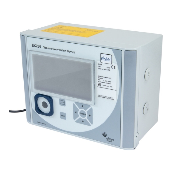
Page 5
EK280 Application Manual 7.5.3 Connection configuration status «StCon» …………….118 7.5.4 Status of remote terminal «SDst» ……………….. 119 7.5.5 GSM modem status «StM» …………………. 120 Registration of the GSM receiving level in a flexible archive …………120 7.6.1 Connection……………………..120 7.6.2… -
Page 6
EK280 Application Manual 9.6.2 Memory capacity ……………………149 9.6.3 Deleting the modification archive ………………. 149 Updates archive ……………………..150 9.7.1 Archive content ……………………150 9.7.2 Memory capacity ……………………150 9.7.3 Delete updates archive ………………….150 Calibration data log ……………………. 151 9.8.1… -
Page 7: General
Avoid improper battery use. Avoid contact with live parts in the EK280 version with internal power supply. Should any instructions in the Application Manual conflict with those given in the Operating Instructions, follow the instructions in the Operating Instructions.
-
Page 8: Ek280 Operation And Display
EK280 Application Manual 2 EK280 Operation and Display 2.1 Display configuration 2.1.1 «Main» main display With the calibration lock open, «Main» on the «Ctrl.» display tab allows you to select different views and contents for the «Main» tab: «Main» Description…
-
Page 9: User Values For The Customer
Connect a PC or laptop with enSuite installed to the EK280 optical interface using the connection cable. Start enSuite and set up the communication link to the EK280. (see chapter 3.1 «Setting up the communication link to the EK280 via optical interface», page 15) …
-
Page 10: Ek280 Archives Display
EK280 Application Manual 2.2 EK280 archives display A comprehensive description of the archive can be found in Chapter 9) To display the contents of an archive, move the cursor to the archive header and press the ENTER or key.
-
Page 11: Search Function For Checking Archive Entries
EK280 Application Manual Display Description All values within an It is not possible to calculate a valid progress index due to a data error in the archive row flash. current archive row. The data error is detected via checksum (CRC).
-
Page 12: Context Menu
EK280 Application Manual 2.3 Context menu The context menu allows you to quickly access specific commands in the various displays. The context menu is accessed using the key. Figure 2: displayed context menu 2.3.1 Jump to main display («Goto Main») The main display («Main»…
-
Page 13: Special Commissioning Function
The counter of the EK280 can be set once in a similar way to that of the gas counter while the administrator lock is open for recording the volume in practice. When the calibration lock is open it is always possible to set the volume and this can also be done directly via the operational volume (tab «Serv.»…
-
Page 14: Parameterize The Volume At Base Conditions
A one-off setting of the volume counter is possible from software version 2.20 while the administrator lock is open. The quantity converter EK280 offers the possibility of adjusting the standard volume counter once during commissioning of the unit while the administrator lock is open. Setting the volume is always possible while the calibration lock is open and can also be carried out directly via Standard Volume (tab «Serv.»…
-
Page 15: Parameterize Display Contrast
(Vb new value) will be set to default values. 2.5 Parameterize display contrast The display contrast of the EK280 can be adjusted to suit the surrounding conditions. Open the administrator lock as described in the EK280 operating manual. …
-
Page 16: Error Messages When Entering Values
EK280 Application Manual 2.6 Error messages when entering values If a value has been entered incorrectly via the keyboard, input error messages will be displayed. Figure: —x— where x = error code according to the following table Code Description The archive is empty. No values have been entered.
-
Page 17: Working With Ensuite
The enSuite parameterization program can be downloaded for free at www.elster.com. Insert the optical read head into the ring on the front panel of the EK280 and connect the other end to a COM or USB port on your PC or laptop.
-
Page 18: Setting Up The Communication Link To Ek280 Via A Network (Tcp/Ip)
3.3 Setting up the communication link to EK280 via a network (TCP/IP) Requirement: A communication link between enSuite and the EK280 (see chapter 7). Ensure your PC or laptop is connected to the LAN. The EK280 must be connected to the same network. …
-
Page 19: Send Parameter File
EK280 Application Manual 3.6 Send parameter file Prerequisite: A communication link between enSuite and the EK280 via optical interface, modem or network (TCP/IP) has been set up (see chapters 3.1 to 3.3). Select «Navigation» on the left-hand side. …
-
Page 20: Lf Pulse Generator (Reed Contact)
4.1 LF Pulse generator (reed contact) 4.1.1 Connection Danger! For EK280 with internal power supply, the mains voltage must be switched off before opening the housing, ensure it is not turned back on and verify that there is no voltage. Pulse generator (Reed contact) …
-
Page 21: Hf Pulse Generator (Namur)
HF Pulse generator (Namur) Connect the gas meter’s high frequency pulse generator (Namur) to terminal «DE1» of the EK280. Release the input 1 (terminal «DE1») calibration seals. 4.2.2 Parameterization Parameterization is carried out via the keyboard on the EK280.
-
Page 22: Encoder
Wait until the «Auto-Encoder» display is updated with a new value. This can take up to a minute as the EK280 activates and test all known encoder protocols consecutively. On successful detection the EK280 displays the label «Vo» on the meter reading of the gas meter: …
-
Page 23
1 instead of «VmG» (total operating volume), then use the «enSuite» parameterization program to send the following parameter file to the EK280 (see chapter 3.6 «Send parameter file», page 17): After loading the WPP file, the measurement period archive, the daily archive and monthly archives 1 and 2 are deleted! … -
Page 24: Hf Pulse Input With Automatic Conversion
4.4 HF pulse input with automatic conversion The EK280 can only count pulses from a high frequency pulse generator via an external power supply, and not battery power. To ensure uninterrupted gas volume measurement, the EK280 can be configured so that it switches to a low frequency pulse generator in the event of failure of the external power supply.
-
Page 25: Parameterization
Application Manual 4.4.2 Parameterization Parameterization is here described with reference to the EK280 keyboard and the above mentioned example. Alternatively, parametrization can be carried out using the enSuite program. The paths which are subsequently described can be found in enSuite under «Parameterize…
-
Page 26: Pulse Comparison
Connect the second low frequency pulse generator (LF reed contact) to terminal «DE2». 4.5.2 Parameterization To program input 2 for the pulse comparison with input 1, send the following parameter file to the EK280 using the parameterization program «enSuite» (see chapter 3.6 «Send parameter file», page 17): …
-
Page 27
The default is 4 («maximum number of disturbance pulses») within a 4000 pulse («pulse window per disturbance pulses»). This setting can be updated using the EK280 keypad or with enSuite: On the «Serv.» display tab of the EK280 keypad: Data book >… -
Page 28: Monitoring The Load At Measurement Conditions Qm In The Archive
2 (Q2) will be archived in flexible archive 12. The maximum record size is 5000 rows. The HF probe of the gas meter (A1S / A1R) must be connected to input 2! The EK280 must be mains supplied in order to be able to record the pulses from the HF probe! 4.6.1 Pulse generator connection…
-
Page 29: Parameterization
4.6.2 Parameterization For programming Input 2 as the measuring input for HF acquisition, use the parameterization program «enSuite» to send the following parameters to EK280 (see Chapter 3.6, Page 17): EK280_xvx. — Application: Qm monitoring (Q2-HF) and storage in Archive 12 (*) After loading of the file, it is also still necessary to set the pc value for input 2 (HF) and the limit,above which any load excess is to be recorded.
-
Page 30: Parameterize The Qm/Qb Load Display
HF transmitter on input 2. As a result, the HF output of the EK280 can respond more quickly to input fluctuations. An external power supply for the EK280 is essential for this purpose, as is the provision of HF pulses by the gas meter (A1S/A1R).
-
Page 31
EK280 Application Manual Setting the high frequency pulse generator’s input mode: Press the key until «Md.I2» is displayed. Press the ENTER button. The set value flashes. Repeatedly press one of the or arrow keys until the text … -
Page 32: Other Number And Status Inputs
Time-synchronous: With a valid input signal the EK280 clock can be synchronized (set) to the full hour. Pulse comparison . A user-defined variation between two pulse generators generates a warning message in the momentary status and status register. Description: See Chapter 4.5 …
-
Page 33: Warning Input Inactive
The status message can then be used, for example to create an archive entry or to switch an output. To program an input as an active information input, send the relevant parameter files from the following to the EK280 using the parameterization program «enSuite» (see chapter 3.6 «Send parameter file», page 17): …
-
Page 34: Time-Synchronous Input
The inputs are already programmed as pulse inputs at the factory so that a conversion is usually superfluous. To program input 3 back to metering, send the following parameter file to the EK280 using the parameterization program «enSuite» (see Chapter 3.6 «Send parameter file», page 17): …
-
Page 35: Archive For The Additional Metering Input (Input 3)
For reliable activation of input 3 as a metering input and for recording in the flexible archive, you transmit the following parameter file to EK280 by means of the «enSuite» parameterizing program in the sub folder «EK280 / «V2xx»-/applications (see Chapter 3.6 «Send parameter file», page17 ): …
-
Page 36: Outputs
For EK280 with internal power supply, the mains voltage must be switched off before opening the housing, ensure it is not turned back on and verify that there is no voltage. Connected device e.g. DL230 Connect the device to one of the desired digital outputs (terminals «DA1» to «DA4») on the EK280.
-
Page 37: Nf Pulse Output (Low-Frequency)
Output 4 Md.O4 The low-frequency pulse output of the EK280 can be operated with active or inactive logic. The output mode must be programmed accordingly for this purpose (see below). Press the ENTER button. The actual parameterized value flashes.
-
Page 38
Application Manual Setting up period length and pulse duration Parametrization of the period length and the pulse duration via the EK280 keyboard is only possible with software version 2.20 or later. Older software versions may be programmed using enSuite via «Parameterize… -
Page 39: Status Output (Signal Output)
Outputs Output 4 Md.O4 The status outputs of the EK280 can be operated with active or inactive logic. The output mode must be programmed accordingly for this purpose (see below). Press the ENTER button. The actual parameterized value flashes.
-
Page 40
= Warning gray = Information. Consequently every alarm would lead to output switching. Press «OK» to accept the setting. After confirmation, the speed button “Transfer changes to device» in enSuite must be used to transmit the values finally to the EK280. -
Page 41: Time-Synchronous Output
Outputs Output 4 Md.O4 The time-synchronized outputs of the EK280 can be operated with active or inactive logic. The output mode must be programmed accordingly for this purpose (see below). Press the ENTER button. The actual parameterized value flashes.
-
Page 42: Hf Pulse Outputs (High Frequency)
1, an FE260 must be used for isolation of the outputs and the power supply in the event of explosion. If output 3 of the EK280 is also to be routed through the FE260 as an F output, this is only possible with an FE260 built later than April 2014.
-
Page 43: Parameterization
EK280 Application Manual 6.5.3 Parameterization Parameterization of the EK280 must be effected with the «enSuite» software, as this is the only way of setting all necessary parameters. The parameters to be set will be found under the following menu headings.
-
Page 44: Continuous Pulse Output
When connecting the outputs to a customer system (e.g. PLC) galvanic separation of both systems is strongly recommended. Especially when using or connecting the EK280 to a hazardous area (hazardous area 1), an external isolation amplifier (permitted for use in hazardous areas) or usage of the FE260 is required.
-
Page 45: Isolating Outputs (Galvanic Isolation)
EK280 Application Manual In particular, when connecting more than one output to a PLC, it must be taken into consideration that under normal operating conditions all 4 outputs have a common earth. Inputs on a PLC often have a common «plus» contact so that all outputs can be switched in parallel.
-
Page 46: Securing The Outputs
(galvanic separation) Galvanic separation of the outputs is not relevant with regard to hazardous areas. If using the EK280 in hazardous area 1 then a permitted, external separator is required which is suitable for use in hazardous areas. An electrically isolated output only requires electricity provided that the output is active (switched on).
-
Page 47: Data Transfer
Unplug the modem from the power supply to avoid damage to the modem and SIM card. This applies also to an EK280 with power supply which is disconnected from the mains, in case a back-up battery supply is connected!
-
Page 48
Connect the modem plug back to the power supply. In case of an EK280 with an internal power supply, the mains voltage must not be switched back on again at this point, otherwise damage to the internal power supply and the internal modem may take place. -
Page 49: Gsm Operation
EK280 via the modem. There are two available time windows, which operate on EK280 battery power only and for versions of the EK280 with power supply there are two more, which operate only on mains voltage. Make the battery power time windows only as long and frequent as absolutely necessary. Each time window reduces the EK280’s battery life.
-
Page 50
The editable time window is not directly reflected in the forecast of the remaining battery life of the batteries» BatR» of the EK280. Therefore the forecast battery life is not changed if the time window is changed. Past time windows and data transfers are however used in the remaining battery capacity «BatRK»… -
Page 51
The test time window only needs to be open if none of the time windows 1 to 4 are open. If the communication link to the EK280 via the optical interface is not set up, it must be created. (see chapter 3.1 «Setting up the communication link to the EK280 via optical interface», page 15) … -
Page 52: Gprs (Tcpserv-Function)
GSM operation, as explained in chapter 7.1.2. Here the GPRS Modem in the EK280 functions as a TCP-Server and may be addressed by a TCP client that is listed in its readout software through a static IP address. To allocate a static IP to the modem during the setup of the GPRS session, they must (together with their GPRS provider) maintain a virtual private network (VPN) which must be enabled on the SIM used in the modem.
-
Page 53
In the base configuration now displayed you can define time windows, during which data can be retrieved cyclically from the EK280 via the modem. There are two available time windows, which operate on EK280 battery power only and for versions of the EK280 with power supply there are two more, which operate only on mains voltage. -
Page 54
The test time window only needs to be open if none of the time windows 1 to 4 are open. If the communication link to the EK280 via the optical interface is not set up, it must be created. (see chapter 3.1 «Setting up the communication link to the EK280 via optical interface», page 15) … -
Page 55: Gprs With Comftp
7.1.4.3 Opening the customer lock In order for ComFTP to read data from the EK280 and save it on the server, at least one EK280 lock must be permanently open. For this purpose it is recommended to use the customer lock, as this contains the least write permissions and therefore avoids the risk of unauthorized parameter updates.
-
Page 56
In the base configuration now displayed you can define time windows, during which data can be retrieved cyclically from the EK280 via the modem. There are two available time windows, which operate on EK280 battery power only and for versions of the EK280 with power supply there are two more which operate only on mains voltage. -
Page 57
The test time window only needs to be open if none of the time windows 1 to 4 are open. If the communication link to the EK280 via the optical interface is not set up, it must be created. (see chapter 3.1 «Setting up the communication link to the EK280 via optical interface», page 15) … -
Page 58
Once the application has been configured, you can check the data transfer to the FTP server using a suitable FTP client (i.e., «Filezilla»). Data should now be automatically transferred from EK280 at the intervals programmed in the ComFTP to the server. -
Page 59: Gprs With Comtsc (Tainy Switching Center)
Then wait a minute, for any communications activity in progress on the EK280 to be safely stopped. b) Send parameter file Send the following parameter file to the EK280 (see Chapter 3.6, «Send parameter file», page 17): EK280_xvx..
-
Page 60
ComTSC modem in accordance with Section 7.1.5.3! You may define time windows which allow you to call off data from EK280 via the modem. There are two available time windows, which operate on EK280 battery power only and for versions of the EK280 with power supply there are two more which operate only on mains voltage. -
Page 61
«ComTSC». Then press the button «Connect»: Having pressed the button «Connect» the dialog box «Settings for application GPRS-TSC» opens. Here you need to enter End device «EK280» and the GPRS provider and enter the TSC login data. -
Page 62
EK280 Application Manual The input of the TSC server address may be in the form of a DNS or the form of an IP address. A secondary TSC server may be entered as an option. When entering the TSC port name and TSC password, appropriate use of lower case and… -
Page 63
The test time window only needs to be open if none of the time windows 1 to 4 are open. If the communication link to the EK280 via the optical interface is not set up, it must be created. (see chapter 3.1 «Setting up the communication link to the EK280 via optical interface», page 15) … -
Page 64
Test retrieval via the modem Set up the modem communication link between enSuite and EK280. (see chapter 3.2 «Setting up the communication link to EK280 via a modem», page 15) For a test retrieval using a conventional GSM-CSD modem connection when in «Tools –… -
Page 65: Replacing The Antenna
7.1.6 Replacing the antenna Danger! For EK280 with internal power supply, the mains voltage must be switched off before opening the housing, ensure it is not turned back on and verify that there is no voltage. If reception via the internal modem is too poor, it is possible to replace the mounted short antenna with SMA connection.
-
Page 66
To check the function, you may now open a time window for testing and check the GSM signal quality on the EK280 display (see Section 7.1.2.2 «Checking GSM field strength», page 48) and for a test call off with enSuite (see Section 7.1.2.3. -
Page 67: Upgrading An Internal Modem
EK280 Application Manual 7.1.7 Upgrading an internal modem For the installation of an internal GSM/GPRS modem in the EK280 at a later date, please proceed as follows. ATTENTION: The permitted modem assembly (73021257 or 73022761) depends on the area in which it is…
-
Page 68
EK280 Application Manual Lead the protective earth wire laterally out of the bore (see illustration)! If this is not done, the antenna cannot be pushed into the correct position. Fasten the antenna by tightening the cable gland (see illustration.) While tightening, hold the antenna from the inside against the cable gland. -
Page 69
To check the function, you may now open a time window for testing and check the GSM signal quality on the EK280 display (see Section 7.1.2.2 «Checking GSM field strength», page 48) and for a test call off with enSuite (see Section 7.1.2.3. Retrieving data with enSuite», page 49). -
Page 70: Em260 To Serial Interface
Ethernet). The name of the parameter file to be used is given further down in the appropriate section. For the connection of the EM260 to EK280, an 8 core cable needs to be used; this is included with the EM260 as supplied.
-
Page 71: Em260 With Analog Modem (Pstn Modem)
In the base configuration now displayed you can define time windows, during which data can be cyclically retrieved from the EK280 via the modem. Time windows 5 and 6 are reserved for EK280 operation with an EM260. Redundant time windows can be deactivated by setting the time window start and end to the same value.
-
Page 72
7.2.2.2 Parameterization of the analog PSTN modem integrated into EM260 If the order for the EM260 stated that it was to be operated connected to an EK280, the parameterization of the EM260 was already effected at the factory, so you may skip this section. -
Page 73
Close the housing of the WM260. Switch on the mains power supply of the EM260 again. The plug symbol in the Main Menu of the EK280 shows the external supply. 7.2.2.3 Retrieving data with enSuite See Section 7.1.2.3 «Retrieving data with enSuite», page 49) -
Page 74: Em260 With Ethernet Adapter
All the values listed in enSuite under «Parameters» can be found on the “Serv.» display tab of the EK280 under the same path. The EK280 will only work with an EM260 model from year 2009 with a Baud rate of 19200. EM260 devices before 2009 need to be operated with a Baud rate of 9600.
-
Page 75
EK280 to the Ethernet adapter. Wait for approx. 1 minute, so that the initialization string can be reliably sent from EK280 to the Ethernet card. Attention! Then it is necessary to perform a Reset of the Ethernet card (interrupt the ext. supply voltage provided by EM260 briefly). -
Page 76
CAUTION! 230 V alternating current Risk to life! For parameterization of the Ethernet adapter in the EM260 for operation with an EK280 you need the USB parameterization cable with the identification no. 73020481 and the ModemIni V3.50 or later which you can order free of charge from Elster. -
Page 77
Push fit the J1 in the uppermost position (see operating instructions for the EM260, Section 10 «Jumper» and photograph on the right). Make sure that the EM260 is connected in accordance with Section 7.2.1 to the EK280. Close housing of EM260… -
Page 78
(in the path «Parameters» > «Interfaces» > «Internal modem»), so that the values correctly set in the modem are not reset by the EK280 after opening of the time window or overwritten by incorrect values. 7.2.3.4 Checking accessibility … -
Page 79: Em260 With Gsm-Modem
All the values listed in enSuite under «Parameters» can be found on the “Serv.» display tab of the EK280 under the same path. The EK280 will only work with an EM260 model from year 2009 with a Baud rate of 19200. EM260 devices before 2009 need to be operated with a Baud rate of 9600.
-
Page 80
CAUTION! 230 V alternating current Risk to life! Start the ModemIni program (V3.50 or later) and perform the following settings: — terminal device: EK280 — Modem box: EM260 — Modem module: GSM-Modem — PC interface: COMx (the COM interface, to which the parameterization cable is connected) … -
Page 81
On the modem adapter board, push-fit the jumper «Mode» in the position «operation» r.h. position, see photograph). Make sure that the EM260 is connected in accordance with Section 7.2.1 to the EK280. Make sure that a SIM card is inserted into the CSM modem. -
Page 82
The test time window only needs to be open if none of the time windows 5 to 6 is currently open. If the communication link to the EK280 via the optical interface is not set up, it must be created. (see chapter 3.1 «Setting up the communication link to the EK280 via optical interface», page 15) … -
Page 83: Fe260 To Serial Interface
FE260 is ordered (2m, 5m or special length) The individual cores must be taken to the inside of the EK280 through one of the metal unions; the housing of the EK280 needs to be opened up for this purpose.
-
Page 84
EK280 Application Manual 7.3.1.1 Wiring FE260 230V AC 230V EK280 Uext+ Uext- 7.3.1.2 EK280 jumpers X6: No jumper X5: two jumpers or a jumper on a pin located closer to the on the pins located terminals. furthest from the terminals. -
Page 85: Fe260 Sim Card Insertion And Unlock
Move the cursor to the «Serv.» tab in the EK280’s display, then to Interfaces > Terminal interface > GSM & GPRS > PIN key and enter the first PIN digit using the and arrow keys.
-
Page 86
EK280 Application Manual 7.3.2.2 SIM in GSM/GPRS module Integra «M2106+» or «M2106B» a) SIM card insertion Danger! Ensure the mains voltage is disconnected before opening the FE260 housing, ensure it is not turned back on and verify that there is no voltage. -
Page 87: Fe260 With Internal Analog Modem (Pstn Modem)
Connect a PC with enSuite installed to the EK280 optical interface using the connection cable. Start enSuite and set up the communication link to the EK280. (see chapter 3.1 «Setting up the communication link to the EK280 via optical interface», page 15) …
-
Page 88
In the base configuration now displayed you can define time windows, during which data can be cyclically retrieved from the EK280 via the modem. Time windows 5 and 6 are reserved for EK280 operation with an FE260, and generally only time window 5 is used. Redundant time windows can be deactivated by setting the time window start and end to the same value. -
Page 89: Fe260 Gsm/Gprs Version, Gsm Operating Mode
In the base configuration now displayed you can define time windows, during which data can be cyclically retrieved from the EK280 via the modem. Time windows 5 and 6 are reserved for EK280 operation with an FE260, and generally only time window 5 is used. Redundant time windows can be deactivated by setting the time window start and end to the same value.
-
Page 90
The test time window only needs to be open if none of the time windows 5 to 6 is currently open. If the communication link to the EK280 via the optical interface is not set up, it must be created. (see chapter 3.1 «Setting up the communication link to the EK280 via optical interface», page 15) … -
Page 91: Fe260 Gsm/Gprs Mode, Gprs/Tcserv
GSM operation, as explained in chapter 7.3.4. Here the GPRS Modem in the EK280 functions as a TCP-Server and may be addressed by a TCP client that is listed in its retrieval software through a static IP address. To allocate a static IP to the modem during the setup of the GPRS session, they must (together with their GPRS provider) maintain a virtual private network (VPN) which must be enabled on the SIM used in the modem.
-
Page 92
In the base configuration now displayed you can define time windows, during which data can be cyclically retrieved from the EK280 via the modem. Time windows 5 and 6 are reserved for EK280 operation with an FE260, and generally only time window 5 is used. Redundant time windows can be deactivated by setting the time window start and end to the same value. -
Page 93
ECM-GW120 instead of «WipSoft». This can happen, for example, if the FE260 has been previously used with an EK260 which is now being swapped for an EK280. Since it was not possible to store the VPN access data in the EK260, it could only be used for TCPserv applications with the modem application «ComTCPserv»! -
Page 94
EK280 Application Manual Jumper «Mode» in Position «program» (lower position) Modem parameterization interface Connect a COM interface of your computer with the modem parameterization interface on the modem adapter board (see photograph) with the aid of a DSUB9-RS232 cable. -
Page 95
«Extended». A dialog box opens for inputting the access data to the VPN: First, the name of your VPN (here «Elster-VPN, for example) will appear. Complete the remaining, initially empty fields with the access data for your VPN which you will obtain from your VPN administrator or from the GPRS network provider. -
Page 96
Before starting a data transfer via the modem, you must ensure that there is adequate reception field strength. On the display of the EK280, move the cursor in the tab «Serv.» to Interfaces >»Terminal interface. > GSM & GPRS > GSM.L … -
Page 97
The test time window only needs to be open if none of the time windows 5 to 6 is currently open. If the communication link to the EK280 via the optical interface is not set up, it must be created. (see chapter 3.1 «Setting up the communication link to the EK280 via optical interface», page 15) … -
Page 98: Fe260 Gsm/Gprs Version With Comftp Modem Application
7.3.6.3 Opening the customer lock In order for ComFTP to read data from the EK280 and save it on the server, at least one EK280 lock must be permanently open. For this purpose it is recommended to use the customer lock, as this contains the least write permissions and therefore avoids the risk of unauthorized parameter updates.
-
Page 99
In call windows 5 and 6 set start and end to the same value for each one and then select the «Transfer changes to device» icon at the top of the enSuite window. Then wait a minute, for any communications activity in progress on the EK280 to be safely stopped. b) Send parameter file … -
Page 100
EK280 Application Manual «ST3» configuration interface Jumper «Mode» in «program» with cable attached position Figure 14: Modem assembly with ECM-GW120 with «Mode» jumper and push-fitted parameterizing cable. Parameterizing interface «Mode» jumper Figure 15: Modem assembly with Integra M2106, «Mode» jumper and parameterization interface. -
Page 101
Refit the «mode» jumper on the FE260 modem board in the «operation» position. 7.3.6.6 EK280 data transfer activation Set up a communication link via the optical interface between enSuite and the EK280 (see chapter 3.1 «Setting up the communication link to the EK280 via optical interface», page 15) again. … -
Page 102: Fe260 Gsm/Gprs Version With Comtsc Modem Application
The SIM card is inserted and unlocked as described in chapter 7.3.2. 7.3.7.2 Parametrization of the EK280 For parameterization of the EK280 you will require a connection cable for the optical interface as well as the enSuite application, which can be downloaded for free at www.elster-instromet.com.
-
Page 103: Fe260 With Ethernet Adapter
FE260! 7.3.8.1 Parameterization of the EK280 for operation with an FE260/Ethernet For parameterization of the EK280 you will require a connection cable for the optical interface as well as the enSuite application, which can be downloaded for free at www.elster-instromet.com.
-
Page 104
«Terminal interface.» Setting time window for potential data retrievals Before the first opening of a time window, the FE260 must first be connected to the EK280 in accordance with Section 7.3.1 and must have been parameterized pursuant to Section 7.3.8.2! See Section 7.2.2.1, paragraph c) on page 69. -
Page 105
EK280 Application Manual Wait for approx. 1 minute, so that the initialization string can be reliably sent from EK280 to the Ethernet card. Attention! Then it is necessary to perform a Reset of the Ethernet card (interrupt the ext. power supply to the FE260 briefly). -
Page 106: Fe260 With Rs232 Interface Card
Connect a PC or laptop with enSuite installed to the EK280 optical interface using the connection cable. Start enSuite and set up the communication link to the EK280. (see chapter 3.1 «Setting up the communication link to the EK280 via optical interface», page 15) …
-
Page 107
In the base configuration now displayed you can define time windows, during which data can be cyclically retrieved from the EK280 via this interface. Time windows 5 and 6 are reserved for EK280 operation with an FE260, and generally only time window 5 is used. Redundant time windows can be deactivated by setting the time window start and end to the same value. -
Page 108: Other Devices To Serial Interface
* In place of DTR you may use RTS (DB-9: Pin 7, DE-25: Pin 4). The signal must run continuously at positive voltage (high-signal) throughout the data transfer. RI may not be used! In EK280 battery operation the signal is switched off again (voltage ≤ 0 V, low signal), in order to preserve the EK280 battery’s life.
-
Page 109
In the base configuration now displayed you can define time windows, during which data can be cyclically retrieved from the EK280 via the modem. Time windows 5 and 6 are reserved for EK280 operation with a direct RS232 connection, and generally only time window 5 is used. Redundant time windows can be deactivated by setting the time window start and end to the same value. -
Page 110: Ex Isolator Mtl5051
The MTL5051 is an approved «associated apparatus» and can therefore be used as an interface isolator, if the EK280 is installed in Zone 1. 7.4.2.1 Connection Explosion hazard! If EK280 operation takes place in a potentially explosive atmosphere, ensure that all safety instructions in the EK280 Operating Instructions are followed. 24 V = MTL5051…
-
Page 111
Connect a PC or laptop with enSuite installed to the EK280 optical interface using the connection cable. Start enSuite and set up the communication link to the EK280 (see chapter 3.1 «Setting up the communication link to the EK280 via optical interface», page 15). … -
Page 112
In the base configuration now displayed you can define time windows, during which data can be cyclically retrieved from the EK280 via the modem. Time windows 5 and 6 are reserved for EK280 operation with an MTL5051, and generally only time window 5 is used. Redundant time windows can be deactivated by setting the time window start and end to the same value. -
Page 113: Rs485 Interface, Electrically Isolated
7.4.3 RS485 interface, electrically isolated 7.4.3.1 Wiring When the EK280 is connected to a RS485 bus there must be no terminal resistors connected to the bus! Due to the current limit for intrinsically-safe apparatus approval, the EK280 cannot supply sufficient current to power terminal resistors.
-
Page 114
The position of the two jumpers on X5 means that the EK280 interface is electrically isolated from the rest of the circuit and therefore electromagnetic interference coupling is prevented. -
Page 115: Rs485 Interface, Without Electrical Isolation
In the base configuration now displayed you can define time windows, during which data can be cyclically retrieved from the EK280 via the RS485 bus. Time windows 5 and 6 are reserved for EK280 operation with a direct terminal interface connection, and generally only time window 5 is used. Redundant time windows can be deactivated by setting the time window start and end to the same value.
-
Page 116
EK280 Application Manual 7.4.4.1.1 Two-wire simplex — wiring This function is only available since EK280 software version 2.20. EK280 Data — Bus Master Data + RS485 Uext+ Power supply 8V (DC) Uext- Data — Further Data + Bus participants 7.4.4.1.2 Four-wire full duplex — wiring… -
Page 117
7.4.4.3 EK280 Parameterization For parameterization of the EK280 you will require a connection cable for the optical interface as well as the enSuite application, which can be downloaded for free at www.elster-instromet.com. Follow the steps given in chapter 7.4.3.3, Parametrization of the EK280, page 112. -
Page 118: Data Transfer Verification
If the conditions for activating the time window connection are satisfied, then the interface is opened and the EK280 is ready to act as a recipient. If a modem is connected to this interface then the EK280 is only ready to act as a recipient after a further 30 seconds.
-
Page 119: Point-In-Time Connection
A point in time connection can be manually initiated at any time (e.g. for a test). To do so, change the parameter «TestC» to 1 («open»). The EK280 opens the interface and attempts to reach the target. In order to follow the progress of the point in time connection, observe the «StCon» parameter and «SDst 1, 2».
-
Page 120: Connection Configuration Status «Stcon
Establishment of a connection has not yet started. The interface is activated specifically for the connection. The interface to be used for the connection (i.e. the modem) is busy, the EK280 will wait until connection can be established. Either the interface has just been used for another connection or the EK280 is waiting to try again after a failed connection attempt.
-
Page 121: Status Of Remote Terminal «Sdst
Disconnection from remote terminal in progress. Disconnection from remote terminal finished. Remote terminal not reached. Check the related EK280-phonebook entry or check the readiness for reception of the remote terminal. Remote terminal refused the connection. Check the related EK280-phonebook entry or check the readiness for reception of the remote terminal.
-
Page 122: Gsm Modem Status «Stm
No additional hardware is needed for the application. The only requirements are the internal GSM/GPRS modem in the EK280 or a GSM/GPRS modem in the FE260. The application May be used with GSM or GPRS modems (however, GPRS data cannot be recorded).
-
Page 123: Evaluation With Ensuite
Modem logged out, battery powered! The modem was unable to log on, as the external power supply failed! E.g. Maybe the EK280 is connected to the lighting system by mistake, so the power to the EK280 is switched off when the light is switched off.
-
Page 124: Data Transmission Protocols
EK280 Application Manual 8 Data transmission protocols 8.1 Modbus 8.1.1 Standard settings of the Modbus Map Following Modbus register assignment is factory-set: Register Short LIS200 Designation / value Format Unit Address Desc.. Address Bat.R Remaining battery life Months 2:404 Stat…
-
Page 125: Formats
EK280 Application Manual 8.1.2 Formats Meanings of formats used: Format Description Format Description Ushort, 16 Bit Array6, BCD, 12 Bit Ulong, 32 Bit Array8, BCD, 16 Bit Counter6 IEEEfloat, 32 Bit Array2, BCD, 4 Bit Code Format Number of registers…
-
Page 126: Modbus Via Rs232 Interface
EK280 Application Manual 8.1.5 Modbus via RS232 interface In the EK280 communication via the terminal interface in RS232 operation can be via Modbus amongst others. Values can be read and updated and archives can be retrieved. 8.1.5.1 Connection RS232 interface connection is described in chapters 7.4.1.1 and 7.4.1.2 8.1.5.2 Parametrization of the EK280…
-
Page 127: Modbus Via Internal Modem (Modbus Rtu_Tcp)
Table 4: Default connection parameters 8.1.6 Modbus via internal modem (Modbus RTU_TCP) In the EK280 communication via the internal GPRS modem in RTU_TCP mode can be via Modbus amongst others. Values can be read and updated and archives can be retrieved.
-
Page 128
EK280 Application Manual b) The «internal modem» interface, the Modbus parameters and the connection parameters for Modbus operation via internal modem are preset in this parameter file. c) Customized settings can be set using enSuite. To do this select «Navigation» on the left-hand side and then «Parameterize… -
Page 129: Operating A Modbus Master
8.2 Operating a Modbus Master Modbus is a stateless single master protocol. Within the Modbus slave function of the EK280 (see Chapter 8.1) the master (retrieval system) can only retrieve the data from the terminal (slave) during an open time window.
-
Page 130: Parameterization Of Modbus Master Tasks
EK280 Application Manual 8.2.2 Parameterization of Modbus master tasks It is established via the Modbus master task list which and how much data shall be read or written. This Modbus master task list, just like the standard Modbus table (see Chapter 8.1.1) contains a maximum of 70 entries (instances).
-
Page 131: Modbus Parameters Which Are Valid For The Entire Device
EK280 Application Manual Address Display Designation Meaning MBAdr «x» MMDir Modbus_Master_AdrDirec Data direction x:7C0 0: H-Wort first tion 1: L Word first MMTrM Modbus_Master_TransMo Transmission mode x:7C1 0: ASCII 1: RTU 2: RTU_TCP MMAdr Modbus_Master_SlaveAd Modbus slave address of x:7C2 Range: 0..247…
-
Page 132
Parameterization of the functions of the RS232 interface is described in Chapter 7.4.1.3. a) Send the parameter file for Modbus parameterization Send the following parameter file to the EK280 (see Chapter 3.6 Send parameter file): EK280_xvx. – RS-232 & Modbus-Master RTU (via connection 8 & ext. power supply) (*) The following Modbus parameters are preset in the file stated above: The first 24 tasks on the task list are processed. -
Page 133
EK280 Application Manual Designation Modbus_Master_ Meaning Address Value Content TaskList_ … …MdbStartAdr Modbus-Adr. 2:8C5 1:100Stat — Momentary status, total …MdbNoReg Disp. 2:8C6 1 Register Register …MdbRegRWMode RW-Mode 2:8C7 2: Write-FC06 …MdbStartAdr Modbus-Adr. 3:8C5 4:302_2VmT — Total actual volume (post- decimal places) [10E-4 m3] …MdbNoReg… -
Page 134
EK280 Application Manual Designation Modbus_Master_ Meaning Address Value Content TaskList_ … …MdbRegRWMode RW-Mode 12:8C7 3: Write-FC16 5:210_1T.Mes — Temperature – measured …MdbStartAdr Modbus-Adr. 13:8C5 value [°C] …MdbNoReg Disp. 13:8C6 2 registers Register …MdbRegRWMode RW-Mode 13:8C7 3: Write-FC16 …MdbStartAdr Modbus-Adr. 14:8C5 5:310C — Conversion factor… -
Page 135: Modbus Master Via Internal Modem (Rtu_Tcp)
Parameterization of the functions of the internal modem is described in Chapter 7.1. a) Send the parameter file for Modbus parameterization Send the following parameter file to the EK280 (see Chapter 3.6 Send parameter file): EK280_xvx. — Modbus-Master RTU-TCP int.Modem Connection7 ext. Power supply (*) The following Modbus parameters are preset in this file: Link 7 is set up for Modbus master communications via the integrated modem.
-
Page 136
EK280 Application Manual Table 14: preprogrammed connection parameters for link 7 (RTU_TCP) The parameters of a link which produce the actual reference to the Modbus are the «Connection_ProtocolType» (states that the Modbus «shall be communicated with») and «Connection_ProtocolInfo» (contains the index regarding the Modbus master information which is relevant for this link). -
Page 137: Sending Sms Messages
If the internal GSM modem is connected (see chapter 7.1) or an external GSM modem respectively an external device including a GSM modem is connected to the serial interface, the EK280 is able to send SMS messages (Short Message Service of GSM-Providers) at occurrence of defined events.
-
Page 138
You can define up to 2 recipients per SMS message, with enSuite change to sub-menu «Interfaces» > «Telephone book» Choose free entries of the EK280 phone book and change to the related sub-menu: Telephone Definition book TelNo Phone number of the recipient including dialing code. -
Page 139
Definition Event EK280 event, at occurrence the message will be transmitted. Within enSuite, press the button and select a status, a unique event or a regular event from the list shown. NoRcv 0 = no conn. (SMS is not active; will not be sent to any recipient) -
Page 140: Archive
EK280 Application Manual 9 Archive Changes to the flexible archive structures which were programmed as factory settings may lead to erroneous processing of read data in a subsequent system. In case of e.g. a power failure, no archived data is lost as all archives are stored in non-volatile memories.
-
Page 141: Memory Capacity
In order to set the measurement period on the device to another value, open the administrator or calibration lock as described in the EK280 operating manual. If at least two entries are still free in the calibration manual then it is possible to change the measurement periods when the administrator lock is open.
-
Page 142: Values Relating To Measurement Periods
9.1.6 Freeze metering period archive This function can be used to store a data row in the measurement period archive. Open the administrator lock as described in the EK280 operating manual. “Menu option 1: With This value is only displayed when the energy”…
-
Page 143: Delete Measurement Period Archive
EK280 Application Manual Move the cursor to «Serv.» > «Archives» > «FrMP». Press the ENTER button «0» flashes. Change the value using the arrow buttons or to «1». Press the ENTER button to confirm the set value. It is possible to abort the entry by pressing the ESC button.
-
Page 144: Memory Capacity
All values relating to daily limits can be created with the daily limit which can be set here. In order to set the daily limit on the device to another value, open the administrator lock as described in the EK280 operating manual. Move the cursor to «Serv.»…
-
Page 145: Time Elapsed Since The Daily Limit
EK280 Application Manual To display the measured values relating to the daily limit, move the cursor to «Serv.» > «Volume conversion» > «per day». Display Description K.Dyc Ø Mean value K of current day K.DyØ Mean value K of last day C.Dyc Ø…
-
Page 146: Monthly Archive 1 (Monthly Meter Readings)
EK280 Application Manual 9.3 Monthly archive 1 (Monthly meter readings) In monthly archive 1 meter readings and maximum consumption figures are archived on a monthly basis based on the monthly limit (= daily limit on the first day of each month) of the previous months.
-
Page 147: Values Relating To Months
EK280 Application Manual 9.3.4 Values relating to months 9.3.4.1 In the current month To display the volumes relating to the monthly limit, move the cursor to «Serv.» > «Volume» > «current month». Display Description Maximum VbMP of current month VbMPc…
-
Page 148: Monthly Archive 2 (Measured Values)
EK280 Application Manual 9.4 Monthly archive 2 (Measured values) In monthly archive 2 maximum, minimum and occasionally median values for Qb, Qm, p, T the previous months are archived on a monthly basis based on the monthly limit (= daily limit on the first day of each month).
-
Page 149: Memory Capacity
EK280 Application Manual Pos. Address Display Description Retrievable 26:0161 C.Mo Mean value C of last month A + S 07:0110 St.7 Instance -Status 7 (incl. p) A + S 06:0110 St.6 Instance -Status 6 (incl. T) A + S 08:0110 St.8 Instance -Status 8 (incl.
-
Page 150: Delete Monthly Archive 2
EK280 Application Manual 9.4.4.2 In the previous month To display the measured values relating to the monthly limit, move the cursor to «Serv.» > «Volume conversion» > «previous month». Display Description K.Mo Ø Mean value K of last month C.Mo Ø…
-
Page 151: Memory Capacity
EK280 Application Manual 9.5.2 Memory capacity The archive can store the last 500 status changes. The manual is a ring-type memory. If the archive is full then the oldest entries are overwritten. 9.5.3 Deleting the manual See Chapter 2.4.2 Clear volumes and archives («Clr.V»).
-
Page 152: Updates Archive
The update archive is also deleted via the function «ClrV» (see Chapter 2.4.2 Clear volumes and archives («Clr.V»)). So that the updates archive is deleted from the device, open the calibration lock as described in the EK280 operating instructions. Move the cursor to «Serv.»…
-
Page 153: Calibration Data Log
With the aid of the calibration data log, several parameters which are relevant from a statutory calibration viewpoint (see the EK280 operating instructions) can be changed when the administrator lock is open. A data row is entered for each alteration of such a parameter when the calibration lock is closed. In addition, an entry is always made when opening and closing the calibration lock.
-
Page 154: Deleting The Calibration Data Log
ESC button. 9.9 User archive The EK280 has five user archives (archive 11, archive 12, archive 13, archive 14 and archive 15). The contents of the user archives can be shown on the display of the device via the path «Serv.»…
-
Page 155: Status Messages
Application Manual 10 Status messages The EK280 gives two types of status information: Momentary status «Stat» (also referred to as «status») and status register «SReg». These are located on the «Admin.» and «Serv.» display tabs under «Status». Messages in the «Stat» momentary status indicate current conditions such as pending errors. As soon as the condition is no longer present, the relevant message is removed from the momentary status.
-
Page 156
Please contact Elster support. b) Warnings: Dat.restaur. E The batteries of the EK280 are intermittently dropping out. As a result of this, the time has not changed and no measurement and volume conversion have happened. However, all data is available. -
Page 157
The administrator / customer lock is open. Cust.lock o. Bat. operat. The EK280 is in battery mode. This signal is primarily used to inform a remote data transmission system that the batteries run down more quickly during long periods of data transmission. -
Page 158
The specified call pickup time is active, i.e. the volume corrector will accept data transmission calls. Call Win.2 Call Win.3 Call Win.4 Call Win.5 Call Win.6 Anr.zeitp1 The specified call time is active, i.e., the EK280 makes a data transmission call to the remote terminal. Anr.zeitp2… -
Page 159: Device Battery Life
……..approx. 5.0 years (readout duration 15 min/week) ……..approx. 5.1 years (readout duration 1 min/day) 10.3.2 Encoder for volume measurement When using other parameter settings for the encoder (e.g. timings) in the EK280 then the battery life may become shorter. Conditions: Batteries: ……
-
Page 160: Additional Pressure Or Temperature Sensors
EK280 Application Manual 10.3.3 Additional pressure or temperature sensors Conditions: Batteries: ……2 battery packs Mode input 1: ….NF pulse input (mode1) Communication: ….Data transfer via modem with «Ring» signal, i.e. internal GSM modem or an analog modem connected to terminals Outputs: ……
-
Page 161: Output Isolation (Galvanic Separation)
The battery capacity required by an isolated output for pulse output is determined by the EK280 and subtracted from the «BatRC» remaining battery life. However as the EK280 does not know how many pulses are to be output in the future, the predicted remaining battery life «Bat.R» is derived from the remaining battery life and calculated based on a default value.
-
Page 162: Monthly Data Transfer
EK280 Application Manual Not only the total duration, but also the number of time windows is relevant to battery life. So for example the battery life for a monthly 4 hour time window is differs from that for four time windows, each lasting 1 hour.
-
Page 163: Data Transfer Duration In Modem Battery Operation
EK280 Application Manual 10.5 Data transfer duration in modem battery operation 10.5.1 Data transfer duration depending on ambient temperature In battery operation the modem battery power is reduced during data transfer. At a low ambient temperature it is reduced more quickly than at a high ambient temperature.
Корректор газа потоковый ЕК280 продолжает линейку корреторов серии ЕК и представляет более широкий функционал по сравнению с корректором ЕК270. Корректор газа потоковый ЕК280 предназначен для приведения рабочего объема газа, прошедшего через счетчик, к стандартным условиям (давление газа — 760 мм. рт.ст., температура газа +20°С) путем вычисления коэффициента сжимаемости газа и коэффициента коррекции с использованием измеренных значений давления, температуры газа и введенных параметров газа.
Подключение дополнительных преобразователей давления и перепада давления, наличие цифровых входы и выходов позволяет организовать на базе ЕК280 систему контроля и управления.
Преобразователи давления и температуры
В отличие от корректора ЕК270 корректор EK280 может быть оснащен до 6 преобразователей давления (2 аналоговых и 4 цифровых) и до 4 преобразователей температуры.
Преобразователи давления используются для изменения абсолютного давления на счетчике (Pa), измерения перепада давления на счетчике и измерения давления еще в одной точке трубопровода, например, перед фильтром.
Преобразователи температуры используются для измерения температуры газа в счетчике и для измерения температуры окружающей среды.
Измеренные и вычисленные данные хранятся в энергонезависимом архиве корректора ЕК280.
Подключение СЧ и ВЧ датчиков и датчиков различного функционала
Наличие высокочастотного входа позволяет подключить к корректору ЕК280 среднечастотный датчик импульсов R300 или высокочастотные датчики импульсов A1K (для RVG) и А1S (для TRZ) и точно вычислять мгновенный расход газа не только при стабильном, но и при импульсном режиме работы оборудования.
Дополнительные НЧ/ВЧ входы позволяют подключить к корректору ЕК280 различные датчики, например датчики загазованности и/или датчики контроля периметра.
Методы вычисления коэффициента сжимаемости
Дополнительно к методам вычисления коэффициента сжимаемости NX19 мод и GERG-91 мод, которые применяются в ЕК270, в корректоре ЕК280 добавлен метод МР113, использующийся для вычисления коэффициента сжимаемости попутного нефтяного газа. Таким образом, корректор ЕК280 может использоваться совместно со счетчиками для учета попутного нефтяного газа.
Независимые интерфейсы RS232/RS485 и встроенный GSM/GPRS модем
Корректор EK280 в дополнение к оптическому и RS232/RS485 интерфейсам может быть оснащён ещё одним RS232/RS485 интерфейсом или встроенным GSM/GPRS модемом с внешней антенной.
В этом случае проводные интерфейсы RS232/RS485 полностью независимы друг от друга и позволяют одновременно передавать данные. Таким образом, и поставщик, и потребитель газа могут иметь одновременный доступ по проводному интерфейсу к корректору EK280.
Модем устанавливается внутри корпуса корректора и использует для питания дополнительный элемент питания. Использование встроенного GSM/GPRS модема позволяет организовать дистанционную передачу данных о потреблении газа на сервер сбора данных в тех местах, где нет возможности подключения дополнительного внешнего питания к корректору ЕК280. В этом случае интерфейсы также полностью независимы друг от друга.
Надежный металлический корпус обеспечивает простоту подключения вторичных устройств и допускает установку корректора на турбинный или ротационный счетчик газа, а так же на стену.
Многоточечный дисплей с крупными символами и подсветкой, в совокупности с семикнопочной клавиатурой, обеспечивают удобный для восприятия интерфейс оператора.
Оптический интерфейс передачи данных, расположенный на лицевой панели, позволяет производить настройку корректора и считывание архивов без коммутации соединительных кабелей. Встроенный в корпус корректора ЕК280 GSM/GPRS модем значительно упрощает процесс дистанционного сбора данных.
-
Contents
-
Table of Contents
-
Bookmarks
Quick Links
3
Operating manual
Volume conversion device
EK280
Related Manuals for Elster EK280
Summary of Contents for Elster EK280
-
Page 1
Operating manual Volume conversion device EK280… -
Page 2
Volume conversion device EK280 Operating manual: 73021209 Version: Issue date: 25.10.13 Software-Version: 2.20 or later… -
Page 3: Table Of Contents
3 Technical data ………………19 3.1 General data ………………19 3.2 Power supply for EK280 without integrated power supply unit ..19 3.2.1 Battery power supply for the basic device ……….. 19 3.2.2 Battery power supply for the integrated modem ……..19 3.2.3 External power supply for the basic device ………
-
Page 4
5.2.6 Connect outputs of the EK280 …………39 5.2.7 Earthing the EK280 housing …………… 40 5.2.8 Earthing the cable connections of the EK280 ……..40 5.2.9 Additional measures for installation in zone 2 ……..41 5.3 Putting into operation …………… 41 5.3.1 Configuration of measurement parameters ……… -
Page 5
General 5.3.4 Verifying assembly and connection …………. 52 6 Operation ………………..53 6.1 Safety ………………..53 6.1.1 Personal protective equipment …………53 6.2 Operating personnel ……………. 53 6.2.1 Instructed personnel …………….53 6.2.2 Qualified personnel …………….53 6.2.3 Calibration officers…………….54 6.3 Basic principles ……………. -
Page 6
General 9 Appendix ………………..82 9.1 List of spare parts and accessories ……….82 9.1.1 Fastening elements …………….82 9.1.2 Pressure connections…………….82 9.1.3 Temperature sensor pockets ………….. 83 9.1.4 Small parts and miscellaneous …………83 9.1.5 Documentation ………………83 9.2 EC Declaration of Conformity ………… -
Page 7: General
The data and material properties indicated serve as reference val- ues. These must be verified on a case-by-case basis and adjusted as necessary. The EK280 Application Manual is available for you at www.elster- instromet.com/en/EK280.html (-> Documents) for the commission- ing of the various communication and device applications.
-
Page 8: Electronic Hotline
In the event of faults, you can also contact the electronic hotline. Tel. +49 (0) 6134 / 605-123 http://www.elster-instromet.com/en/support_electronics.html E-mail: support@elster.com 1.4 Meaning of symbols 1.4.1 Safety information In this manual, safety information is denoted by the use of symbols. The safety in- formation is introduced by signal words which identify the level of risk.
-
Page 9: Tips And Recommendations
General 1.4.2 Tips and recommendations … provides useful tips and recommendations as well as infor- mation for ensuring efficient and smooth operations. 1.5 Limitationof liability All of the information contained in this manual has been compiled under considera- tion of valid standards and regulations, the latest technological developments, and our many years of experience and expertise.
-
Page 10: Scope Of Delivery
The free «enSuite» program also belongs to the accessories for the EK280 and is available under www.elster-instromet.com. This can be used to program the EK280 volume conversion device via its data interfaces to perform advanced applications.
-
Page 11: Storage
General 1.9 Storage CAUTION! Exceeding or falling below the valid temperature range for the batteries may impair performance. If the valid temperature range of the batteries during storage of the device is exceeded or fallen below, the performance of the batter- ies may be impaired.
-
Page 12: Safety
– If category «II 3 G» has been marked on the ATEX label, the EK280 should not be used in zone 1, but only in zone 2. – The ATEX label is located on the top panel of the EK280 hous- ing.
-
Page 13
Operating the EK280 in zone 1 and connecting devices which are not certified as «associated equipment» present a risk of explosion. Therefore: – When using the EK280 in zone 1, it should only be connected to certified associated equipment as per the ATEX Product Di- rective 94/9/EC. -
Page 14: Intended Use
This device is solely designed and constructed for the intended use described be- low. The volume conversion device EK280 is used to convert the gas volume read from a gas pipe under measurement conditions, into base conditions, as well as to allo- cate the measured quantities to tariffs.
-
Page 15: Personal Protective Equipment
Safety Gas specialists who, on the basis of their specialist training, knowledge and experience, as well as their awareness of the relevant standards and regulations, are in a position to perform works on gas-handling equipment and to independently identify possi- ble risks.
-
Page 16: Specific Risks
Safety 2.5 Specific risks The residual risks arising from the risk assessment will be listed below. Please ob- serve the safety and warning information specified in the following chapters to re- duce risks to health and to prevent dangerous situations from arising. WARNING! Misuse of batteries may present a risk of injury.
-
Page 17: Environmental Protection
Safety 2.6 Environmental protection CAUTION! Environmentally hazardous substances! If environmentally hazardous substances are handled incorrectly this may cause significant damage to the environment, particularly if they are improperly dis- posed of. Therefore: – The instructions below should be observed at all times. –…
-
Page 18: Operator’s Responsibility
Safety 2.7 Operator’s responsibility The device will be used in the commercial sector. The operator of the device will therefore be subject to legal obligations concerning occupational safety. In addition to the safety information contained in these instructions, the valid safety, accident prevention, and environmental protection regulations for the area of appli- cation of the device, must be adhered to.
-
Page 19: Technical Data
Permissible ambient temperature range -25 … +55 °C Permissible gas temperature range -30 … +60 °C 3.2 Power supply for EK280 without integrated power supply unit 3.2.1 Battery power supply for the basic device Data Value Unit Voltage General nominal capacity 16.5…
-
Page 20: External Power Supply For The Basic Device
Supply voltage 7.5 …8.5 Supply current, maximum 3.3 Power supply for EK280 with integrated power supply unit 3.3.1 Battery power supply for the basic device Batteries for switching to battery mode in the event of a power failure: see chapter 3.3.1 «Battery power supply for the basic device»…
-
Page 21: Pressure Sensor Type 17002
16 … 80 bar abs. 105 bar abs. The pressure sensor is available as both an external and internal model. Further details can be found under www.elster-instromet.com or chapter «Assembly, Connection and Putting into Operation». 3.4.1.2 Relative pressure ranges Measuring range Overload capacity ……
-
Page 22: Temperature Sensor
Technical data The pressure sensor is available as both an external and internal model. Further details can be found under www.elster- instromet.com or chapter «Assembly, Connection and Putting into Operation». 3.5 Temperature sensor Data Value Unit Measuring range -30 … +60 °C…
-
Page 23: Hf Pulse Inputs (High Frequency)
Technical data 3.6.2 HF pulse inputs (high frequency) High frequency pulse transducers can only be connected to inputs 1 and 2 (termi- nals DE1 and DE2) (see chapter 5.2.1.3). Data Value Unit Open-circuit voltage 7.5 … 8.5 «High» switching level max.
-
Page 24: Hf Pulse Outputs
Technical data 3.7.3 HF pulse outputs The use of outputs as high frequency output is only possible if an external power supply has been connected (see chapter 5.2). Only outputs 2 and 3 (terminals DA2 and DA3) can be used as high frequency out- put.
-
Page 25: Labeling
(MID). The label is placed on the front panel of the device (see Construction and Function chapter). 3.10.1 Type label of the volume corrector The type label of the EK280 relating to its function as a volume corrector, contains the following information: 1 Type designation EK280…
-
Page 26: Atex Marking
Technical data 3.10.2 ATEX marking The plate for the «Ex» marking of the EK280 is located on the top panel of the de- vice housing. 3.10.2.1 Zone 1 (without integrated power supply unit) ELSTER GmbH II 1 G 55252 Mainz- Kastel…
-
Page 27: Construction And Function
Construction and Function 4 Construction and Function 4.1 External view 1 Display 2 Cable bushings for the connec- tion of additional components 3 Optical interface Identification label 4 Escape button «ESC» 5 Enter button «ENTER» 6 Function key , ⊳ 7 Arrow keys 8 Pressure sensor Instromet…
-
Page 28: Short Description
Construction and Function 4.3 Short description The volume conversion device EK280 is an explosion-protected electronic device that takes the volume of gas determined by an external meter at measurement con- ditions to calculate the volume at base conditions and therefore the energy portion of the respective gas volume.
-
Page 29: Assembly, Connection And Putting Into Operation
– Do not open when an explosive atmosphere may be present! – Electrostatic hazard: Do not rub! The EK280 can either be mounted on a gas meter, on a pipeline, or on a wall. Should problems arise during assembly, e.g. with regard to the selec- tion of suitable assembly tools, please contact our customer service team (see «General»…
-
Page 30: Assembly On A Gas Meter
Assembly, Connection and Putting into Operation 5.1.1 Assembly on a gas meter Mount the EK280 on a gas meter using a mounting bracket (see Ap- pendix) as well as the corresponding cylinder screws and square nuts. 1. Using two M5 x 10 mm (Fig. 6: cylinder screws, attach the mounting bracket (Fig.
-
Page 31: Assembly On A Wall
Select wall plugs which corre- spond to the size of the screws and insert these in the boreholes in the wall. To fasten the EK280, four M5 x 40 mm wood screws should be used for wall as- sembly. Fig. 8 5.1.4 Three-way valve…
-
Page 32: Connection
The connection of non intrinsically-safe or non-associated equipment presents a risk of explosion! The operation of the EK280 in zones 1 and 2 and the connection of non intrinsically-safe equipment which exceeds those conditions and limit values specified in the declaration of conformity, presents a risk of explosion.
-
Page 33: Connecting The Gas Meter
5.2.1 Connecting the gas meter In order to measure the gas volume, a gas meter with a low or high frequency pulse transducer or encoder can be connected to the digital input «DE1» of the EK280. The pulse transducer or encoder of the gas meter will be connected to the «DE1″…
-
Page 34
— not when in battery mode. In order to ensure an uninterrupted measurement of the gas volume, the EK280 can be configured in such a way that the device automatically switches to a low fre- quency pulse transducer in the event of a failure of the external power supply;… -
Page 35: Sealing The Input Terminals
Assembly, Connection and Putting into Operation 5.2.2 Sealing the input terminals After connecting to the gas meter as per chapter 5.2.1, the input terminal «DE1» must be sealed for official calibration measurements. For this purpose, terminal covers are provided in the bag of accessories. If required, these should be screwed over the connected terminals and an adhesive seal should then be bonded to the fastening screw (see chapter 5.3.2).
-
Page 36: Connecting The Pressure Pipe
Assembly, Connection and Putting into Operation 5.2.3.2 Connection to an older temperature sensor pocket Insert the temperature sensor Pt500 into the temperature sensor pocket (see Appendix). Use the adapter to seal the connec- tion (see Appendix). Fasten the temperature sensor using the capstan screw and the screw connections…
-
Page 37: Connecting The Power Supply
Operating the EK280 in zone 1 and connecting devices which are not certified as «associated equipment» present a risk of explosion. Therefore: – When using the EK280 in zone 1, it should only be connected to certified associated equipment as per the ATEX Product Di- rective 94/9/EC.
-
Page 38
Assembly, Connection and Putting into Operation 5.2.5.2 Power supply for the EK280 with integrated power supply unit DANGER! Danger to life from electrical current! Touching live parts poses an imminent danger to life. Therefore: – Works on the electrical components of the device, i.e. the con- nection of the power supply unit, should solely be carried out by qualified electricians. -
Page 39: Connect Outputs Of The Ek280
Assembly, Connection and Putting into Operation 5.2.6 Connect outputs of the EK280 The cable core diameter for the connection to the EK280 outputs is 0.33 … 2.5 mm Different downstream devices can be connected to the digital out- puts of the EK280. The outputs are preconfigured for this purpose (see chapter 5.3.1.13).
-
Page 40: Earthing The Ek280 Housing
Use the cable to connect the screw on the left-hand side of the housing with the equipotential bonding strip. 5.2.8 Earthing the cable connections of the EK280 All cables firmly connected to the EK280 have a shield. This is connected to the cable glands of the EK280 in order to prevent electromagnetic interference.
-
Page 41: Additional Measures For Installation In Zone 2
8 mm M16, plastic: 8 mm The ATEX category «II 1 G» models of the EK280 (without in-built power supply unit) should be installed in both zones 1 and 2 without these additional measures. 5.3 Putting into operation 5.3.1 Configuration of measurement parameters If the EK280 is subject to calibration regulations, the works described below should only be performed by legally authorized individuals.
-
Page 42
Assembly, Connection and Putting into Operation 5.3.1.1 Opening the calibration lock The calibration lock is located at the back of the housing cover in the form of a but- ton, and this can be secured by means of an adhesive label. This button must be pressed in order to adjust the values and parameters protected by configuration regulations. -
Page 43
If an encoder is connected as per 5.2.1.2, the encoder mode is activated as follows: Start the «Auto Detect» function using the keyboard of the EK280 as follows: Move the cursor to the «Serv.» register and to the value «Md.I1» (input mode) via the following path: Serv. -
Page 44
Assembly, Connection and Putting into Operation 5.3.1.4 Adjusting the parameters for the high frequency pulse transducer of the gas meter If a high frequency pulse transducer is connected as per 5.2.1.3, the input mode and the cp value should be adjusted as follows: 1. -
Page 45
In order to control the recording of the volume at measurement conditions, the EK280 meter can be set once to the same value as the gas meter if the administra- tor lock is open. It is always possible to set the volume if the calibration lock is open: Open the administrator lock or the calibration lock Move the cursor to the „Serv.“… -
Page 46
5.3.1.8 Setting the volume at base conditions For the EK280 volume conversion device, there is the option available when com- missioning the device to set the volume at base conditions meter once if the admin- istrator lock is open. It is always possible to set the volume if the calibration lock is… -
Page 47
Assembly, Connection and Putting into Operation 5.3.1.9 Deleting change information for comparison of Vb with the gas meter In order to allow the volume at base conditions to be reset if the administrator lock is open, the change information for comparison of „Vb“ must be deleted: Open the calibration lock Move the cursor to the „Serv. -
Page 48
Assembly, Connection and Putting into Operation 5.3.1.11 Adjust alarm limits for gas pressure and temperature measurement Alarm limits are set to default values ex-factory. If a change becomes necessary, please proceed as follows: Move the cursor to the «Serv.» register and move to the alarm limit values via the following paths: Serv. -
Page 49
Aside from the settings described here, a range of other functions can be configured for the outputs, e.g. high frequency or time- synchronous pulses. A complete description can be found in the EK280 Application Manual that can be downloaded under www.elster-instromet.com. 5.3.1.14 Setting the daylight saving time Move the cursor to the «Serv.»… -
Page 50
All measurement archives (no logs) will be deleted. In order to ensure that the archive is not accidentally deleted, the serial number of the EK280 must be entered whilst the calibration lock is open (the number is located on EK280 identification plate). -
Page 51: Sealing
Assembly, Connection and Putting into Operation 5.3.2 Sealing 5.3.2.1 External view Possible sealing point to se- cure the identification plate via adhesive seal. EK280 Year: 2011 Optional user lock: Seal co- Serialno.: 1234567 M 11 0102 vers using wire seals through…
-
Page 52: Closing The Housing
Fig. 22 5.3.4 Verifying assembly and connection WARNING! Risk as a result of incorrect assembly and connection Incorrect assembly and connection of the EK280 may lead to life- threatening situations. Therefore: – Assemble and connect the EK280 correctly. – Sealing should solely be carried out by a calibration officer.
-
Page 53: Operation
EK280, and to perform changes which are not subject to calibra- tion regulations.
-
Page 54: Calibration Officers
EK280, and to perform changes which are not subject to calibra- tion regulations. 6.3 Basic principles As already explained in the «Construction and Function»…
-
Page 55: Display
Operation 6.3.1 Display The display is divided into the five registers «Main», «Cust.», «Admin», «Serv.» and «Ctrl.» under which measurements, settings and other data are displayed. Fig. 24 Display layout Device status Battery charge status Frozen display Active register External power supply Inactive register Reception strength of the external Cursor…
-
Page 56: Button Functions
Operation 6.3.2 Button functions The pressure and arrow buttons have the following functions: Button Function Jump right to another data list. Jump to the second part of a two-part value. Jump down through a data list. ⊳ Jump left to another data list. Jump up through a data list.
-
Page 57: Data Recall, Display Navigation
Operation 6.3.3 Data recall, display navigation ⊳ Using the arrow keys , you can move the cursor around the display and switch to the other values. By pressing the ESC button one or more times, you will be directed to the «Main», «Cust.», «Admin», «Serv.»…
-
Page 58: Meaning Of Status Symbols
Operation 6.3.4 Meaning of status symbols The status symbols displayed in the first line have the following meaning: Fig. 26: Status symbols in the display Symbol Meaning In the upper left-hand side of the screen, individual letters are dis- played as symbols for the following signals: No special message.
-
Page 59: Error Messages When Entering Values
External power supply If this symbol appears, the EK280 is being supplied power from an ex- ternal unit connected to the terminals. Signal strength of the radio network for the external modem (connected to the terminals).
-
Page 60: Access Rights
As this address has not yet been entered, no value will be displayed. The value can only be changed when the calibration lock is open as the PTB log is full. 6.3.6 Access rights The following parties can access the EK280. Access Meaning Calibration officer…
-
Page 61
This includes all values which influence volume readings or the volume conversion. The calibration lock is designed as a button which is positioned inside the EK280 housing underneath the circuit board cover. It can be protected with an adhesive la- bel (see chapter 5.3.1.1, «Opening the calibration lock»). -
Page 62: Data Register Content
Operation 6.3.6.3 Administrator and customer locks Administrator and customer locks are used to protect data which is not subject to calibration regulations, but which should also not be modified without authorization. These locks can be opened by entering a code (i.e. the «key») under “Cod.A” or “Cod.C”…
-
Page 63
The calculated compressibility ratio factor is used to calculate the volume at base conditions. The EK280 supports several equations to calculate the compressibility ratio factor. The corresponding equation is determined by the applicable guidelines and stand- ards for the area of application of the device. This can be adjusted at the ordering or commissioning phase ( chapter 5.3.1 «Configuration of measurement parame-… -
Page 64: Cust.» Register (Customer)
Operation 6.4.3 «Cust.» register (Customer) This register is used to display and check special device settings and conditions. This application is provided for gas customers. This register can be freely programed by the user via the enSuite configuration software. The following parameters are programed in-house: Display Meaning Unit…
-
Page 65
Operation 6.4.3.4 VbMP↑ ↑ ↑ ↑ – Maximum measurement period counter Vb in the current month The maximum time stamp is displayed in the following line after moving the cursor to the value «VbMP↑». The maximum values from the past 15 months can be requested in the monthly ar- chive 1 (see chapter 6.4.4 «Admin»… -
Page 66: Admin» Register (Administrator)
Operation 6.4.4 «Admin» register (Administrator) This register is used to display and check special device settings and conditions. This application is provided for metering point operator. Display Meaning User values Sub-menu for user-specific parameters Volume Sub-menu for volume and the corresponding parameters Volume con- Sub-menu for volume conversion and the corresponding parameters version…
-
Page 67: Serv.» Register (Service)
Operation 6.4.5 «Serv.» register (service) This register is used to display, check and configure special device settings and conditions. This application is only intended for service technicians (specialists) or a calibration officer for putting the device into operation or maintenance. Display Meaning Volume…
-
Page 68
(see chapter 6.3.4 «Meaning of status symbols») 6.4.6.4 Menu — Selection of the display menu In an as-delivered condition, the display of the EK280 has the following five regis- ters: «Main», «Cust.”, «Admin», «Serv.» and «Ctrl.». Registers can be displayed and… -
Page 69
Operation 6.4.6.5 Main – Content of the «Main» register The content of the «Main» display register can be adjusted here. The default setting is «volume+meas.”. This corresponds to the content displayed in chapter 6.3.1. Display Meaning volume+meas. — The following are displayed: Volume at base conditions, vol- ume at measurement conditions, pressure, temperature, compressibility ratio factor and conversion factor — Format: 8 pre-decimal and 3 post-decimal places for counters… -
Page 70: Maintenance
Maintenance 7 Maintenance 7.1 Safety DANGER! Danger to life from electrical current! Touching live parts poses an imminent danger to life. Damage to the insulation or individual components may be life-threatening. Therefore: – Safely protect electrical connections and live components against possible human contact.
-
Page 71: Personnel
Maintenance CAUTION! Environmentally hazardous substances! If environmentally hazardous substances are handled incorrectly this may cause significant damage to the environment, particularly if they are improperly disposed of. Therefore: – The instructions below should be observed at all times. – Appropriate measures should be taken immediately if environ- mentally hazardous substances are accidentally released into the environment.
-
Page 72: Testing And Changing Device Batteries
In an as-delivered condition, two batteries are connected to the base board of the EK280. To double the service life of the batteries, two additional batteries can be connected. You should always connect at least two batteries (to X10 and X13 or X11 and X14) to the EK280.
-
Page 73
Fig. 29 and repeat step 11 if necessary. Please ensure that the new batteries are connected correctly and are in a fixed position inside the EK280. CAUTION! Material damage may arise through improper closing of the device! Improper closing of the device may lead to material damage as a result of cable connections being squashed. -
Page 74: Entering The Battery Capacity
Maintenance 7.2.2 Entering the battery capacity The battery capacity must be re-entered after changing a battery. When using the device with high communication security („High Level Security“, see application manual), the battery capacity can only be entered with the enSuite software! For opening the administrator lock move the cursor to the «Admin»…
-
Page 75: Display Remaining Battery Power
Maintenance 7.2.3 Display remaining battery power The remaining battery power is calculated separately from the consumed power (which is measured) and from the anticipated fu- ture consumption (giving the theoretical remaining battery power). Therefore, for applications which are very power-consuming, the remaining battery power may drop quicker than is shown on the battery power display.
-
Page 76: Faults
(see chapter General) or our Electronic Hotline: Tel. +49 (0) 6134 / 605-123 http://www.elster-instromet.com/en/support_electronics.html E-mail: support@elster-instromet.com 8.1 Safety DANGER! Danger to life from electrical current! Touching live parts poses an imminent danger to life. Damage to the insulation or individual components may be life-threatening.
-
Page 77: Personal Protective Equipment
Faults 8.1.2 Personal protective equipment When eliminating faults on the device, the necessary personal protective equipment for the work must be worn inside the respective plant. The notices relating to personal protective equipment mounted in the working area must be followed at all times. 8.1.3 Improper elimination of faults WARNING! Risk of injury through improper elimination of faults!
-
Page 78: Fault And Other Status Messages
Faults 8.2 Fault and other status messages Faults (synonymously used here for «alarms») during the operation of the EK280, can be identified by means of status symbols in the first line of the display (see chapter 6.3.4). You can obtain further information and messages under the current status «Stat»…
-
Page 79
Please contact the Elster support (see chapter 1.3 «Customer service»). b) Warnings: The batteries of the EK280 are intermittently dropping out. As a Data restore result of this, the time has not changed and no measurement and volume conversion have happened. However, all data is available. -
Page 80
Before the software update, an error was detected in the cached software image. Softw. error This message is used for factory diagnosis. Please contact the Elster support (see chapter 1.3 «Customer service»). The programing of the device has generated an unusable com- Sett. error bination of settings. -
Page 81
If this message appears for more than several minutes, the func- tion «Automatically set time via RDT» is activated. However, if this does not work, please contact the Elster support (see chap- ter 1.3 «Customer service»). Cal.lock o. -
Page 82: Appendix
Appendix Message Meaning, action Bat. operat. The EK280 is in battery mode. This signal is primarily used to inform a remote data transmis- sion system that the batteries run down more quickly during long periods of data transmission. Dayl.Sav.Tim The time displayed in volume corrector is daylight saving time.
-
Page 83: Temperature Sensor Pockets
700 mm long Device: Battery module 13 Ah 73 015 774 16 Ah battery module for the modem of the EK280 without inte- 73 021 211 grated power supply unit 13 Ah battery module for connection to the integrated power sup-…
-
Page 84: Ec Declaration Of Conformity
Appendix 9.2 EC Declaration of Conformity…
-
Page 85: Atex Type Examination Certificate
Appendix 9.3 ATEX Type Examination Certificate 9.3.1 Zone 1…
-
Page 86
Appendix… -
Page 87
Appendix… -
Page 88
Appendix… -
Page 89
Appendix… -
Page 90: Zone 2
Appendix 9.3.2 Zone 2…
-
Page 91
Appendix…