- Manuals
- Brands
- YOKOGAWA Manuals
- Transmitter
- Dpharp EJX110A
Manuals and User Guides for YOKOGAWA Dpharp EJX110A. We have 4 YOKOGAWA Dpharp EJX110A manuals available for free PDF download: User Manual, Installation Manual
YOKOGAWA Dpharp EJX110A User Manual (66 pages)
Differential Pressure and Pressure Transmitters
Brand: YOKOGAWA
|
Category: Transmitter
|
Size: 3.11 MB
Table of Contents
-
Table of Contents
2
-
1 Introduction
4
-
Regarding this Manual
4
-
Safe Use of this Product
5
-
Warranty
6
-
ATEX Documentation
7
-
-
2 Handling Cautions
8
-
Model and Specifications Check
8
-
Unpacking
8
-
Storage
8
-
Selecting the Installation Location
9
-
Pressure Connection
9
-
Waterproofing of Cable Conduit Connections
9
-
Restrictions on Use of Radio Transceivers
9
-
Insulation Resistance and Dielectric Strength Test
9
-
Installation of an Explosion-Protected Instrument
10
-
FM Approval
10
-
CSA Certification
12
-
CENELEC ATEX (KEMA) Certification
14
-
Iecex Certification
17
-
-
EMC Conformity Standards
18
-
Pressure Equipment Directive (PED)
18
-
Low Voltage Directive
19
-
-
3 Component Names
20
-
4 Installation
21
-
Precautions
21
-
Mounting
21
-
Changing the Process Connection
22
-
Swapping the High/Low-Pressure Side Connection
23
-
Rotating Pressure-Detector Section 180
23
-
Using the Communicator
23
-
-
Rotating Transmitter Section
24
-
Changing the Direction of Integral Indicator
24
-
-
5 Installing Impulse Piping
25
-
Impulse Piping Installation Precautions
25
-
Connecting Impulse Piping to a Transmitter
25
-
Routing the Impulse Piping
26
-
-
Impulse Piping Connection Examples
28
-
-
6 Wiring
29
-
Wiring Precautions
29
-
Selecting the Wiring Materials
29
-
Connections of External Wiring to Terminal Box
29
-
Power Supply Wiring Connection
29
-
External Indicator Connection
29
-
Communicator Connection
29
-
Check Meter Connection
30
-
Status Output Connection
30
-
-
Wiring
30
-
Loop Configuration
30
-
General-Use Type and Flameproof Type
30
-
Intrinsically Safe Type
30
-
-
Wiring Installation
30
-
General-Use Type and Intrinsically Safe Type
30
-
Flameproof Type
31
-
-
-
Grounding
31
-
Power Supply Voltage and Load Resistance
31
-
-
7 Operation
32
-
Preparation for Starting Operation
32
-
Zero Point Adjustment
33
-
Adjusting Zero Point for Differential Pressure Transmitters
34
-
Adjusting Zero Point for Gauge/Absolute Pressure Transmitters
34
-
-
Starting Operation
34
-
Shutting down the Transmitter
35
-
Venting or Draining Transmitter Pressure-Detector Section
35
-
Draining Condensate
35
-
Venting Gas
35
-
-
Setting the Range Using the Range-Setting Switch
36
-
-
8 Maintenance
37
-
Overview
37
-
Calibration Instruments Selection
37
-
Calibration
37
-
Disassembly and Reassembly
39
-
Replacing the Integral Indicator
39
-
Replacing the CPU Board Assembly
40
-
Cleaning and Replacing the Capsule Assembly
40
-
Replacing the Process Connector Gaskets
41
-
-
Troubleshooting
42
-
Basic Troubleshooting
42
-
Troubleshooting Flowcharts
43
-
Alarms and Countermeasures
45
-
-
-
9 General Specifications
46
-
Standard Specifications
46
-
Performance Specifications
46
-
Functional Specifications
46
-
-
Model and Suffix Codes
50
-
Optional Specifications
50
-
Optional Specifications
55
-
Dimensions
58
-
Advertisement

YOKOGAWA Dpharp EJX110A Installation Manual (57 pages)
EJX Series and EJA-E Series Differential Pressure and Pressure Transmitters
Brand: YOKOGAWA
|
Category: Transmitter
|
Size: 16.44 MB
Table of Contents
-
Table of Contents
1
-
1 Introduction
2
-
For Safe Use of Product
3
-
Warranty
5
-
ATEX Documentation
6
-
-
2 Handling Cautions
7
-
Model and Specifications Check
8
-
Selecting the Installation Location
8
-
Pressure Connection
8
-
Installation of an Explosion-Protected Instrument
8
-
EMC Conformity Standards
28
-
Pressure Equipment Directive (PED)
29
-
Safety Requirement Standards
30
-
-
3 Installation
31
-
Mounting
31
-
Mounting the Diaphragm Seals
31
-
Diaphragm Seals Installation Consideration
32
-
Mounting the Flushing Connection Ring
33
-
3.5 Affixing The Teflon Film
34
-
Rotating Transmitter Section
35
-
Changing the Direction of Integral Indicator
35
-
-
4 Installing Impulse Piping
36
-
Impulse Piping Installation Precautions
36
-
Routing the Impulse Piping
37
-
Impulse Piping Connection Examples
38
-
Process Piping Installation Precautions (EJ115)
39
-
-
5 Wiring
41
-
Wiring Precautions
41
-
Connections of External Wiring to Terminal Box
41
-
Power Supply Wiring Connection
42
-
Status Output Connection
42
-
-
Wiring
44
-
Wiring Installation
45
-
RTD Cable Connection (EJX910A/EJX930A)
46
-
Grounding
48
-
Power Supply Voltage and Load Resistance
48
-
-
6 Operation
49
-
Preparation for Starting Operation
49
-
Zero Point Adjustment
49
-
Local Parameter Setting
50
-
-
7 Errors and Countermeasures
52
YOKOGAWA Dpharp EJX110A Installation Manual (60 pages)
Differential Pressure and Pressure Transmitters
Brand: YOKOGAWA
|
Category: Transmitter
|
Size: 11.44 MB
Table of Contents
-
Table of Contents
1
-
1 Introduction
2
-
For Safe Use of Product
4
-
Warranty
6
-
-
2 Handling Cautions
7
-
3 Installation
35
-
Mounting
35
-
-
4 Installing Impulse Piping
40
-
5 Wiring
45
-
Wiring Precautions
45
-
Wiring
48
-
Grounding
52
-
-
6 Operation
53
-
Preparation for Starting Operation
53
-
-
7 Errors and Countermeasures
56
Advertisement
YOKOGAWA Dpharp EJX110A User Manual (20 pages)
Differential Pressure and Pressure Transmitters
Brand: YOKOGAWA
|
Category: Transmitter
|
Size: 2.55 MB
Table of Contents
-
Table of Contents
2
-
Introduction
5
-
Regarding this Manual
5
-
Safe Use of this Product
6
-
Warranty
7
-
ATEX Documentation
8
-
Handling Cautions
9
-
Model and Specifications Check
9
-
Unpacking
9
-
Storage
9
-
Selecting the Installation Location
10
-
Pressure Connection
10
-
Waterproofing of Cable Conduit Connections
10
-
Restrictions on Use of Radio Transceivers
10
-
Insulation Resistance and Dielectric Strength Test
10
-
Installation of an Explosion-Protected Instrument
11
-
FM Approval
11
-
CSA Certification
13
-
Iecex Certification
18
-
EMC Conformity Standards
19
-
Pressure Equipment Directive (PED)
19
-
Low Voltage Directive
20
-
Installation
20
Advertisement
Related Products
-
YOKOGAWA DpharpEJX vigilantplant EJX130A
-
YOKOGAWA DpharpEJX vigilantplant EJX110
-
YOKOGAWA DP harp EJX120A
-
YOKOGAWA EJX118A
-
YOKOGAWA EJX115A
-
YOKOGAWA DP Harp EJX118B
-
YOKOGAWA EJX110B
-
YOKOGAWA EJX Series
-
YOKOGAWA DpharpEJX vigilantplant EJX910A
-
YOKOGAWA Dpharp vigilantplant EJA Series
YOKOGAWA Categories
Measuring Instruments
Test Equipment
Transmitter
Controller
Media Converter
More YOKOGAWA Manuals
Page 1 — IM 01C25B01-01E
User’sManualDifferential Pressure andPressure TransmittersEJ110, EJ120, EJ130, EJ310, EJ430, and EJ440IM 01C25B01-01EIM 01C25B01-01E13th E
Page 2 — Contents
<2. Handling Cautions>2-2IM 01C25B01-01E2.4 Selecting the Installation Location The transmitter is designed to withstand severe environmen
Page 3
<2. Handling Cautions>2-3IM 01C25B01-01E(b) Never apply a voltage exceeding 500 V DC (100 V DC with an internal lightning protector) for t
Page 4 — Revision Information
<2. Handling Cautions>2-4IM 01C25B01-01EIMPORTANTFor combined approval typesOnce a device of multiple approval type is installed, it should
Page 5 — 1. Introduction
<2. Handling Cautions>2-5IM 01C25B01-01ENote 4. Maintenance and Repair• The instrument modication or parts replacement by other than aut
Page 6 — <1. Introduction>
<2. Handling Cautions>2-6IM 01C25B01-01E2.9.2 CSA Certicationa. CSA Intrinsically Safe TypeCaution for CSA Intrinsically safe and noninc
Page 7 — 1.2 Warranty
<2. Handling Cautions>2-7IM 01C25B01-01E• Explosion-proof for Class I, Groups B, C and D.• Dustignition-proof for Class II/III, Groups E,
Page 8 — 1.3 ATEX Documentation
<2. Handling Cautions>2-8IM 01C25B01-01E2.9.3 ATEX Certication(1) Technical Dataa. ATEX Intrinsically Safe Ex ia Caution for ATEX Intri
Page 9 — 2. Handling Cautions
<2. Handling Cautions>2-9IM 01C25B01-01Eb. ATEX Flameproof TypeCaution for ATEX ameproof type.Note 1. Model EJX/EJA-E Series pressure tr
Page 10
<2. Handling Cautions>2-10IM 01C25B01-01E● ATEX Intrinsically Safe Ex icCaution for ATEX intrinsically safe Ex ic• Applicable Standard: E
Page 11
<2. Handling Cautions>2-11IM 01C25B01-01E(5) Maintenance and Repair WARNING The instrument modication or parts replacement by other than
Page 12 — IMPORTANT
iIM 01C25B01-01EDifferential Pressure and Pressure TransmittersEJ110, EJ120, EJ130,EJ310, EJ430, and EJ440IM 01C25B01-01E 13th Edition13t
Page 13
<2. Handling Cautions>2-12IM 01C25B01-01E• Installation RequirementsUo ≤ Ui, Io ≤ Ii, Po ≤ Pi, Co ≥ Ci + Ccable, Lo ≥ Li + Lcable Voc ≤
Page 14 — 2.9.2 CSA Certication
<2. Handling Cautions>2-13IM 01C25B01-01E2.11 Pressure Equipment Directive (PED)(1) General• EJX/EJA-E Series pressure transmitters are
Page 15
<3. Component Names>3-1IM 01C25B01-01E3. Component NamesHIGH LOWSlide switchBurnout direction switchWrite protection switchBurnout Directi
Page 16 — 2.9.3 ATEX Certication
<4. Installation>4-1IM 01C25B01-01E4. Installation4.1 Precautions Before installing the transmitter, read the cautionary notes in section
Page 17
<4. Installation>4-2IM 01C25B01-01EF0403.aiVertical pipe mounting(Process connector upside)Vertical pipe mounting(Process connector downsid
Page 18
<4. Installation>4-3IM 01C25B01-01E4.4 Swapping the High/Low-pressure Side ConnectionIMPORTANTThis section is applicable only for EJ110,
Page 19 — 2.9.4 IECEx Certication
<4. Installation>4-4IM 01C25B01-01E4.5 Rotating Transmitter SectionThe transmitter section can be rotated approximately 360° (180° to eith
Page 20
<5. Installing Impulse Piping>5-1IM 01C25B01-01E5. Installing Impulse Piping5.1 Impulse Piping Installation PrecautionsThe impulse piping
Page 22 — 3. Component Names
<5. Installing Impulse Piping>5-3IM 01C25B01-01E5.1.2 Routing the Impulse Piping(1) Process Pressure Tap AnglesIf condensate, gas, sedime
Page 24 — Connection
<5. Installing Impulse Piping>5-4IM 01C25B01-01E(7) Preventing FreezingIf there is any risk that the process uid in the impulse piping or
Page 26 — High Pressure Type)
<6. Wiring>6-2IM 01C25B01-01E6.3.4 Check Meter ConnectionAvailable only when /AL is not specied.Connect the check meter to the CHECK + an
Page 28 — (Figure 5.3)
<7. Operation>7-1IM 01C25B01-01E7. Operation7.1 Preparation for Starting OperationThis section describes the operation procedure for the
Page 29
<7. Operation>7-2IM 01C25B01-01EVent plug (Fill plug)Tap valveStop valveDrain valveF0702.aiFigure 7.1b Liquid Pressure Measurement Conrm
Page 30 — Examples
<7. Operation>7-3IM 01C25B01-01E7.2.1 Adjusting Zero Point for Differential Pressure TransmittersBefore adjusting zero point, make sure th
Page 31 — 6. Wiring
<7. Operation>7-4IM 01C25B01-01EIMPORTANT• Remove the communicator from the terminal box, and conrm that none of the terminal screws are
Page 32 — 6.4 Wiring
<7. Operation>7-5IM 01C25B01-01E7.5.2 Venting Gas1) Gradually open the vent screw to vent gas from the transmitter pressure-detector sec
Page 33 — Load Resistance
<7. Operation>7-6IM 01C25B01-01EIMPORTANT• Do not turn off the power to the transmitter immediately after completion of the change in the
Page 36 — 7.3 Starting Operation
<8. Maintenance>8-2IM 01C25B01-01ETable 8.1 Instruments Required for CalibrationName Yokogawa-recommended Instrument RemarksPower supply M
Page 38 — Range-setting Switch
<8. Maintenance>8-4IM 01C25B01-01E8.4.2 Replacing the CPU Board AssemblyThis subsection describes the procedure for replacing the CPU asse
Page 39
<8. Maintenance>8-5IM 01C25B01-01E Removing the Capsule AssemblyIMPORTANTExercise care as follows when cleaning the capsule assembly.• H
Page 40 — 8. Maintenance
<8. Maintenance>8-6IM 01C25B01-01E8.4.4 Replacing the Process Connector GasketsThis subsection describes process connector gasket replacem
Page 41
<8. Maintenance>8-7IM 01C25B01-01E8.5.2 Troubleshooting FlowchartsConnect communicator and check self-diagnostics.Does the self-diagnostic
Page 42 — Reassembly
<8. Maintenance>8-8IM 01C25B01-01EConnect a communicator and check self-diagnostics.Contact Yokogawa service personnel.F0809.aiAre valves o
Page 43 — Assembly
<8. Maintenance>8-9IM 01C25B01-01E8.5.3 Alarms and CountermeasuresTable 8.3 Alarm Message SummaryIndicator CauseOutput Operationduring Er
Page 44
<9. General Specications>9-1IM 01C25B01-01E9. General Specications9.1 Standard SpecicationsRefer to IM 01C25T02-01E for FOUNDATION Fie
Page 45 — 8.5 Troubleshooting
<1. Introduction>1-1IM 01C25B01-01E1. IntroductionThank you for purchasing the DPharp Differential Pressure and pressure transmitter.Your
Page 46 — <8. Maintenance>
<9. General Specications>9-2IM 01C25B01-01EEJA120E Measurement Span/RangekPa inH2O(/D1) mbar(/D3) mmH2O(/D4)ESpan 0.1 to 1 0.4 to 4 1 to 1
Page 47
<9. General Specications>9-3IM 01C25B01-01E Normal Operating Condition(Selected features may affect limits.)Ambient Temperature Limits –
Page 48
<9. General Specications>9-4IM 01C25B01-01EMaximum Over PressureEJ310Capsule PressureL, M 500 kPa abs (72 psia)A 16 MPa abs (2300 psia)B
Page 49 — 9. General Specications
<9. General Specications>9-5IM 01C25B01-01E Physical SpecicationsWetted Parts MaterialsDiaphragm, Cover Flange, Process Connector, Caps
Page 50
<9. General Specications>9-6IM 01C25B01-01E9.2 Model and Sufx CodesModel EJX110AModel Sufx Codes DescriptionEJX110A . . . . . . . . .
Page 52
<9. General Specications>9-8IM 01C25B01-01EModel EJX130AModel Sufx Codes DescriptionEJX130A . . . . . . . . . . . . . . . . . . . . . .
Page 53 — Physical Specications
<9. General Specications>9-9IM 01C25B01-01EModel EJX310AModel Sufx Codes DescriptionEJX310A . . . . . . . . . . . . . . . . . . . . . .
Page 55 — Model EJX120A
<9. General Specications>9-11IM 01C25B01-01EModel EJX440AModel Sufx Codes DescriptionEJX440A . . . . . . . . . . . . . . . . . . . . . .
Page 56 — Model EJX130A
<1. Introduction>1-2IM 01C25B01-01E• Yokogawa assumes no responsibilities for this product except as stated in the warranty.• If the cust
Page 57 — Model EJX310A
<9. General Specications>9-12IM 01C25B01-01EModel EJA110EModel Sufx Codes DescriptionEJA110E . . . . . . . . . . . . . . . . . . . . .
Page 58 — Model EJX430A
<9. General Specications>9-13IM 01C25B01-01EModel EJA120EModel Sufx Codes DescriptionEJA120E . . . . . . . . . . . . . . . . . . . . .
Page 59 — Model EJX440A
<9. General Specications>9-14IM 01C25B01-01EModel EJA130EModel Sufx Codes DescriptionEJA130E . . . . . . . . . . . . . . . . . . . . .
Page 60 — Model EJA110E
<9. General Specications>9-15IM 01C25B01-01EModel EJA310EModel Sufx Codes DescriptionEJA310E . . . . . . . . . . . . . . . . . . . . .
Page 61 — Model EJA120E
<9. General Specications>9-16IM 01C25B01-01EModel EJA430EModel Sufx Codes DescriptionEJA430E . . . . . . . . . . . . . . . . . . . . .
Page 62 — Model EJA130E
<9. General Specications>9-17IM 01C25B01-01EModel EJA440EModel Sufx Codes DescriptionEJA440E . . . . . . . . . . . . . . . . . . . . .
Page 63 — Model EJA310E
<9. General Specications>9-18IM 01C25B01-01ETable. 1 Wetted Parts Materials for EJ110, EJ120, EJ310, and EJ430Wetted partsmateria
Page 64 — Model EJA430E
<9. General Specications>9-19IM 01C25B01-01E9.3 Optional Specications Item Description CodeFactory Mutual (FM) FM Explosionproof *1Explo
Page 65 — Model EJA440E
<9. General Specications>9-20IM 01C25B01-01EItem Description CodeOil-prohibited use with dehydrating treatment *4Degrease cleansing treatm
Page 66
<9. General Specications>9-21IM 01C25B01-01E*9: Also see ‘Ordering Instructions’.*10: Applicable for M, H and V capsules of EJX110A with
Page 68
<9. General Specications>9-22IM 01C25B01-01E9.4 DimensionsModel EJ110Unit: mm (approx. inch)95(3.74)242(9.53)175(6.89)129(5.08)97(3.82)
Page 69
<9. General Specications>9-23IM 01C25B01-01EUnit: mm (approx. inch)54(2.13)6(0.24)Electrical connectionfor code 5, 9, A, and D.Process con
Page 70 — Model EJ110
<9. General Specications>9-24IM 01C25B01-01EUnit: mm (approx. inch)54(2.13)6(0.23)129(5.08)117(4.61)*154(2.13)ø78(3.07)ø70(2.76)39(1.54)12
Page 71 — Unit: mm (approx. inch)
<9. General Specications>9-25IM 01C25B01-01EModel EJ120Unit: mm (approx. inch)54(2.13)6(0.24)Electrical connectionfor code 5, 9, A, and
Page 72 — F0907.ai
<9. General Specications>9-26IM 01C25B01-01EUnit: mm (approx. inch)54(2.13)6(0.24)ø78(3.07)ø70(2.76)Integral indicator (optional)Ground te
Page 73 — F0908.ai
<9. General Specications>9-27IM 01C25B01-01EModel EJ130Unit: mm (approx. inch)54(2.13)6(0.24)Process connection93(3.66)124(4.88)277(10.9
Page 74 — F0909.ai
<9. General Specications>9-28IM 01C25B01-01EUnit: mm (approx. inch)54(2.13)6(0.24)ø78(3.07)ø70(2.76)Integral indicator (optional)Ground te
Page 75 — Model EJ130
<9. General Specications>9-29IM 01C25B01-01EModel EJ310Unit: mm (approx. inch)223(8.78)52(2.05)97(3.82)41(1.61)67(2.64)Process connectio
Page 76 — F0911.ai
<9. General Specications>9-30IM 01C25B01-01EUnit: mm (approx. inch)54(2.13)6(0.24)129(5.08)59*1(2.32)27(1.06)ø78(3.07)ø70(2.76)39(1.54)12(
Page 77 — F0912.ai
<9. General Specications>9-31IM 01C25B01-01EModel EJ430Unit: mm (approx. inch)223(8.78)52(2.05)97(3.82)41(1.61)67(2.64)Process connectio
Page 78 — F0914.ai
<1. Introduction>1-4IM 01C25B01-01E1.3 ATEX DocumentationThis is only applicable to the countries in European Union.GBDKIENLSFPFDSLTLVPLES
Page 79 — Model EJ430
<9. General Specications>9-32IM 01C25B01-01EUnit: mm (approx. inch)54(2.13)6(0.24)Electrical connectionfor code 5, 9, A, and D.Process con
Page 80 — F0916.ai
<9. General Specications>9-33IM 01C25B01-01EUnit: mm (approx. inch)54(2.13)6(0.24)129(5.08)59*1(2.32)27(1.06)ø78(3.07)ø70(2.76)39(1.54)12(
Page 81 — F0918.ai
<9. General Specications>9-34IM 01C25B01-01EModel EJ440 Unit: mm (approx. inch)54(2.13)6(0.24)54(2.13)6(0.24)Process connection119(4.69)
Page 82 — Model EJ440
<9. General Specications>9-35IM 01C25B01-01EUnit: mm (approx. inch)54(2.13)6(0.24)ø78(3.07)ø70(2.76)Integral indicator (optional)Ground te
Page 83 — F0920.ai
iIM 01C25B01-01ERevision Information Title : Differential Pressure and Pressure Transmitters EJ110, EJ120, EJ130, EJ310, EJ430, and EJ
Page 84
iiIM 01C25B01-01EEdition Date Page Revised Item7th Feb. 2008 — Change of the style code, add EJX120A.General • Change the gure of amplier housing.1-
Page 85
<2. Handling Cautions>2-1IM 01C25B01-01E2. Handling CautionsThis chapter provides important information on how to handle the transmitter.
-
Contents
-
Table of Contents
-
Troubleshooting
-
Bookmarks
Quick Links
User’s
Manual
Y okogawa Electric Corporation
EJX110A, EJX130A, EJX310A,
EJX430A and EJX440A
Differential Pressure and
Pressure Transmitters
IM 01C25B01-01E
IM 01C25B01-01E
5th Edition
Related Manuals for YOKOGAWA DpharpEJX vigilantplant EJX110
Summary of Contents for YOKOGAWA DpharpEJX vigilantplant EJX110
-
Page 1
User’s Manual EJX110A, EJX130A, EJX310A, EJX430A and EJX440A Differential Pressure and Pressure Transmitters IM 01C25B01-01E IM 01C25B01-01E 5th Edition Y okogawa Electric Corporation… -
Page 2: Table Of Contents
Selecting the Wiring Materials …………6-1 Connections of External Wiring to Terminal Box …….. 6-1 6.3.1 Power Supply Wiring Connection ……….6-1 FD No. IM 01C25B01-01E IM 01C25B01-01E 5th Edition: July 2006(YK) All Rights Reserved, Copyright © 2004, Yokogawa Electric Corporation…
-
Page 3
CONTENTS 6.3.2 External Indicator Connection …………6-1 6.3.3 Communicator Connection …………6-1 6.3.4 Check Meter Connection ………….. 6-2 6.3.5 Status Output Connection …………6-2 Wiring ………………..6-2 6.4.1 Loop Configuration …………… 6-2 General-use Type and Flameproof Type ……..6-2 Intrinsically Safe Type …………..6-2 6.4.2 Wiring Installation …………….. -
Page 4: Introduction
• All rights reserved. No part of this manual may be before you operate the instrument. reproduced in any form without Yokogawa’s written permission. • Yokogawa makes no warranty of any kind with NOTE regard to this manual, including, but not limited to, This manual describes the hardware configura- implied warranty of merchantability and fitness for a tions of EJX series transmitters.
-
Page 5: Safe Use Of This Product
Indicates a potentially hazardous situation which, protection provided by this instrument may be im- if not avoided, could result in death or serious paired. In this case, Yokogawa cannot guarantee that injury. the instrument can be safely operated. Please pay…
-
Page 6: Warranty
Yokogawa. (f) Modification • The purchaser shall bear the responsibility for repair • Yokogawa will not be liable for malfunctions or costs, even during the warranty period, if the damage resulting from any modification made to this malfunction is due to: instrument by the customer.
-
Page 7: Atex Documentation
Se si desidera ricevere i manuali operativi di prodotti Ex in lingua locale, mettersi in Alle Betriebsanleitungen für ATEX Ex bezogene contatto con l’ufficio Yokogawa più vicino o con un Produkte stehen in den Sprachen Englisch, Deutsch rappresentante.
-
Page 8: Handling Cautions
2. HANDLING CAUTIONS HANDLING CAUTIONS This chapter provides important information on how to 2.1 Model and Specifications handle the transmitter. Read this carefully before using Check the transmitter. EJX Series transmitters are thoroughly tested at the The model name and specifications are written on the factory before shipment.
-
Page 9: Selecting The Installation Location
2. HANDLING CAUTIONS (b) Make sure that there are no leaks in the impulse 2.4 Selecting the Installation piping. Location (c) Never apply a pressure higher than the specified maximum working pressure. The transmitter is designed to withstand severe environmental conditions. However, to ensure that it 2.6 Waterproofing of Cable will provide years of stable and accurate performance, take the following precautions when selecting the…
-
Page 10: Installation Of An Explosion-Protected Instrument
• Ambient temperature: –60 to 60 C intrinsically safe or explosionproof construction may be compromised and the instrument may be hazardous to operate. Please contact Yokogawa before making any repair or modification to an instrument. IM 01C25B01-01E…
-
Page 11
[Groups A, B, C, D, E, F and G] by other than authorized representative of Vmax = 30 V Ci = 6 nF Yokogawa Electric Corporation is prohibited and Imax = 200 mA Li = 0 H will void Factory Mutual Intrinsically safe and Pmax = 1 W Nonincendive Approval. -
Page 12: Csa Certification
• Ambient Temperature :–50 to 60 C by other than authorized representative of • Max. Process Temp.: 120 C Yokogawa Electric Corporation is prohibited and • Enclosure: IP66 and IP67 will void Factory Mutual Explosionproof Approval. Note 2. Entity Parameters •…
-
Page 13
2. HANDLING CAUTIONS Note 2. Wiring [Intrinsically Safe] Hazardous Location Nonhazardous Location [For CSA C22.2] Group IIC, Zone 0 • All wiring shall comply with Canadian Electrical Class I, II, III, Division 1, Code Part I and Local Electrical Codes. Groups A, B, C, D, E, F, G General •… -
Page 14: Cenelec Atex (Kema) Certification
Explosionproof) for use in hazardous locations. by other than authorized representative of Note 1. For the installation of this transmitter, Yokogawa Electric Corporation is prohibited and once a particular type of protection is will void KEMA Intrinsically safe Certification. selected, any other type of protection Note 5.
-
Page 15
• The instrument modification or parts replacement Note 4. Operation by other than authorized representative of • Keep the “WARNING” label attached to the Yokogawa Electric Corporation is prohibited and transmitter. will void Type of Protection “n”. WARNING: AFTER DE-ENERGIZING, DELAY 5 MINUTES BEFORE OPENING. -
Page 16
*2: “180-8750” is a zip code which represents the following address. WARNING 2-9-32 Nakacho, Musashino-shi, Tokyo Japan The instrument modification or parts replacement by other than an authorized Representative of Yokogawa Electric Corporation is prohibited and will void the certification. IM 01C25B01-01E… -
Page 17: Iecex Certification
/SU2 can be selected the type of by other than authorized representative of protection (IECEx Intrinsically Safe/type n or Yokogawa Electric Corporation and will void flameproof) for use in hazardous locations. IECEx Intrinsically safe and type n certification.
-
Page 18: Emc Conformity Standards
• The instrument modification or parts replacement EJX310A 0.01 Article 3, Paragraph 3 M, A, B by other than authorized representative of (SEP) Yokogawa Electric Corporation is prohibited and EJX430A 0.01 Article 3, Paragraph 3 H, A, B will void IECEx Certification. (SEP)
-
Page 19: Low Voltage Directive
2. HANDLING CAUTIONS 2.12 Low Voltage Directive Applicable standard : EN61010-1 (1) Pollution Degree 2 «Pollution degree» describes the degree to which a soild, liquid, or gas which deteriorates dielectric strength or surface resistivity is adhering. » 2 » applies to normal indoor atmosphere. Normally, only non-conductive pollution occurs.
-
Page 20: Component Names
3. COMPONENT NAMES COMPONENT NAMES Vertical impulse piping type Pressure-detector section Terminal box cover Cover flange Horizontal impulse piping type External indicator (Note 1) conduit connection Conduit connection Zero- adjustment screw (Note 2) Slide switch Integral (Note 1) indicator Mounting screw Vent plug CPU assembly Drain plug…
-
Page 21: Installation
4 . INSTALLATION INSTALLATION 4.1 Precautions Vertical pipe mounting Before installing the transmitter, read the cautionary notes in section 2.4, “Selecting the Installation Loca- tion.” For additional information on the ambient conditions allowed at the installation location, refer to Transmitter subsection 9.1 “Standard Specifications.”…
-
Page 22: Changing The Process Connection
4 . INSTALLATION 4.3 Changing the Process Con- Vertical pipe mounting (Process connector downside) nection Transmitter The transmitter is shipped with the process connection mounting bolt specified at the time of ordering. To change the process connection,the drain (vent) plug must be repositioned. Mounting bracket To reposition a drain (vent) plug, use a wrench to slowly and gently unscrew it.
-
Page 23: Swapping The High/Low-Pressure Side Connection
4 . INSTALLATION 4.4 Swapping the High/Low- 4.4.2 Using the Communicator pressure Side Connection This method is applicable only to the Model EJX110A and EJX130A. With a communicator, you can change which process IMPORTANT connection is used as the high-pressure side without This section is applicable only for EJX110A and mechanically rotating the pressure-detector section 180 EJX130A differential transmitters, and not…
-
Page 24: Rotating Transmitter Section
4 . INSTALLATION 4.5 Rotating Transmitter Section 4.6 Changing the Direction of Integral Indicator The transmitter section can be rotated approximately 360 (180 to either direction or 360 to one direction from the original position at shipment, depending on IMPORTANT the configuration of the instrument.) It can be fixed at any angle within above range.
-
Page 25: Installing Impulse Piping
5. INSTALLING IMPULSE PIPING INSTALLING IMPULSE PIPING 5.1 Impulse Piping Installation (2) Changing the Process Connector Piping Connections (Figure 4.1) (for differential Precautions pressure transmitters) The impulse piping that connects the process outputs to The impulse piping connection distances can be the transmitter must convey the process pressure changed between 51 mm, 54 mm and 57 mm by accurately.
-
Page 26: Routing The Impulse Piping
5. INSTALLING IMPULSE PIPING 3) Install the pipe assemblies between the 3-valve NOTE manifold and the process connectors and lightly tighten the ball head lock nuts. (The ball-shaped ends of the pipes must be handled carefully, since After completing the connection of the transmit- they will not seal properly if the ball surface is ter and 3-valve manifold, be sure to CLOSE the scratched or otherwise damaged.)
-
Page 27
5. INSTALLING IMPULSE PIPING (2) Position of Process Pressure Taps and (6) Preventing Wind Speed Effects in Very Transmitter Low Differential Pressure Measurement (for differential pressure transmitters) If condensate (or gas) accumulates in the impulse piping, it should be removed periodically by opening the drain (or vent) plugs. -
Page 28: Impulse Piping Connection Examples
5. INSTALLING IMPULSE PIPING 5.2 Impulse Piping Connection Liguid Steam Examples Orifice Condensate pot Figure 5.5 and 5.6 show examples of typical impulse valve piping connections. Before connecting the transmitter to the process, study the transmitter installation Union location, the process piping layout, and the characteris- or flange tics of the process fluid (corrosiveness, toxicity, flammability, etc.), in order to make appropriate…
-
Page 29: Wiring
6. WIRING WIRING 6.1 Wiring Precautions 6.3 Connections of External Wiring to Terminal Box 6.3.1 Power Supply Wiring Connection IMPORTANT Connect the power supply wiring to the SUPPLY + • Lay wiring as far as possible from electrical and – terminals. When /AL is specified, also refer to noise sources such as large capacity transform- subsection 6.3.5.
-
Page 30: Check Meter Connection
6. WIRING (1) General-use Type and Flameproof Type 6.3.4 Check Meter Connection Available only when /AL is not specified. Hazardous Location Nonhazardous Location Connect the check meter to the CHECK + and – Transmitter terminal box terminals. (Use hooks.) Distributor (Power supply unit) •…
-
Page 31: Flameproof Type
6. WIRING 6.5 Grounding (2) Flameproof Type Wire cables through a flameproof packing adapter, or Grounding is always required for the proper operation use a flameproof metal conduit. of transmitters. Follow the domestic electrical require- Wiring cable through flameproof packing adapter. ments as regulated in each country.
-
Page 32: Operation
7. OPERATION OPERATION 7.1 Preparation for Starting Venting Gas from the Transmitter Pressure- detector Section Operation • Since the piping in the example of figure 7.1 is constructed to be self-venting, no venting operation is This section describes the operation procedure for the required.
-
Page 33: Zero Point Adjustment
7. OPERATION NOTE Vent plug (Fill plug) If any of the above errors are indicated on the display of the integral indicator or the communi- Tap valve cator, refer to subsection 8.5.3 for the corrective action. Stop valve Verify and Change Transmitter Parameter Setting and Values The parameters related to the following items are set at factory as specified in order.
-
Page 34: Adjusting Zero Point For Differential Pressure Transmitters
7. OPERATION (2) When you cannot obtain the Low Range 7.2.1 Adjusting Zero Point for Differential Value from the actual measured value of 0%; Pressure Transmitters Adjust the transmitter output to the actual measured Before adjusting zero point, make sure that the equaliz- value obtained by a digital manometer or a glass ing valve is open.
-
Page 35: Shutting Down The Transmitter
7. OPERATION 7.5.1 Draining Condensate • Tighten the zero-adjustment cover mounting screw to secure the cover. 1) Gradually open the drain screw or drain plug and drain the transmitter pressure-detector section. (See figure 7.5.) 7.4 Shutting Down the Transmitter 2) When all accumulated liquid is completely re- moved, close the drain screw or drain plug.
-
Page 36: Setting The Range Using The Range-Setting Switch
7. OPERATION Note 1: Wait until the pressure inside the pressure-detector section 7.6 Setting the Range Using the has stabilized before proceeding to the next step. Range-setting Switch Note 2: If the pressure applied to the transmitter exceeds the previous LRV (or URV), the integral indicator may display error number “AL.30”…
-
Page 37: Maintenance
8. MAINTENANCE MAINTENANCE 8.1 Overview 8.2 Calibration Instruments Se- lection WARNING Table 8.1 lists the instruments that can be used to calibrate a transmitter. When selecting an instrument, Since the accumulated process fluid may be consider the required accuracy level. Exercise care toxic or otherwise harmful, take appropriate care when handling these instruments to ensure they to avoid contact with the body or inhalation of…
-
Page 38
0.1% or higher level, there may be difficulties in calibration to this level in the field. For calibration to the 0.1% level, contact Yokogawa representatives from which the instrument was purchased or the nearest Yokogawa office. -
Page 39: Disassembly And Reassembly
Phillips screwdriver JIS B4633, No. 2 indicator to a transmitter. If such modification is Slotted screwdriver absolutely required, contact Yokogawa. Allen wrenches JIS B4648 One each, nominal 3, 4 and 2.5 mm Allen wrenches…
-
Page 40: Replacing The Cpu Board Assembly
If the capsule. you wish to replace the capsule assembly with one of a different measurement range, contact Yokogawa. NOTE The user is permitted, however, to replace a Be careful not to apply excessive force to the capsule assembly with another of the same CPU assembly when removing it.
-
Page 41: Replacing The Process Connector Gaskets
8. MAINTENANCE Removing the Capsule Assembly 7) After completing reassembly, adjust the zero point and recheck the parameters. IMPORTANT Transmitter section Exercise care as follows when cleaning the capsule assembly. • Handle the capsule assembly with care, and be especially careful not to damage or distort the diaphragms that contact the process fluid.
-
Page 42: Troubleshooting
Process connector gasket complex causes, these flow charts may not identify all. If you have difficulty isolating or correcting a problem, contact Yokogawa service personnel. 8.5.1 Basic Troubleshooting First determine whether the process variable is actually abnormal or a problem exists in the measurement system.
-
Page 43: Troubleshooting Flowcharts
Fix pressure leaks, paying particular attention to connections for impulse Adjust the zero point. piping,pressure-detector section, etc. Is there Contact Yokogawa service personnel. continuity through the transmitter loop wiring? F0808.EPS Do the loop numbers match? Find/correct broken conductor or wiring error.
-
Page 44
Provide lagging and/or cooling, or allow adequate ventilation. Were appropriate instruments used for calibration? Refer to Section 8.2 when selecting instruments for calibration. Is output adjusted correctly? Adjust the output. Contact Yokogawa service personnel. F0809.EPS IM 01C25B01-01E… -
Page 45: Alarms And Countermeasures
8. MAINTENANCE 8.5.3 Alarms and Countermeasures Table 8.1 Alarm Message Summary Output Operation Indicator Cause Countermeasure during Error None Sensor problem. Outputs the signal (Hold, Replace capsule when error AL. 01 High, or Low) set with keeps appearing even CAP. ERR parameter.
-
Page 46: General Specifications
9. GENERAL SPECIFICATIONS GENERAL SPECIFICATIONS Failure Alarm “ ” 9.1 Standard Specifications Output status at CPU failure and hardware error; Up-scale: 110%, 21.6 mA DC or more (standard) Refer to IM 01C25T02-01E for FOUNDATION Fieldbus Down-scale: –5%, 3.2 mA DC or less communication type marked with “…
-
Page 47
9. GENERAL SPECIFICATIONS EJX130A EJX310A Capsule Pressure 100(750) M, H 32 MPa (4500 psi) M,A and B capsule EJX310A L capsule Capsule Pressure 10(75) 130 kPa abs (38 inHg abs) 3.5 MPa abs (500 psia) 16 MPa abs (2300 psia) 2.7(20) Working Applicable range… -
Page 48
9. GENERAL SPECIFICATIONS Supply & Load Requirements “ ” (Optional features Use the following formula to determine cable length for or approval codes may affect electrical require- specific applications: ments.) With 24 V DC supply, up to a 550 load can be used. See + 10,000) –… -
Page 49
9. GENERAL SPECIFICATIONS Connections Refer to “MODEL AND SUFFIX CODE.” Process Connection of Cover Flange(models except for EJX440A- D) : IEC61518 IM 01C25B01-01E… -
Page 50: Model And Suffix Codes
9. GENERAL SPECIFICATIONS 9.2 MODEL AND SUFFIX CODES MODEL EJX110A Model Suffix Codes Description EJX110A Differential pressure transmitter · · · · · · · · · · · · · · · · · · · · · · · · · Output signal 4 to 20 mA DC with digital communication (BRAIN protocol) -D ·…
-
Page 51
9. GENERAL SPECIFICATIONS MODEL EJX310A Model Suffix Codes Description · · · · · · · · · · · · · · · · · · · · · · · · · Absolute pressure transmitter EJX310A Output Signal -D ·… -
Page 52
9. GENERAL SPECIFICATIONS MODEL EJX430A Model Suffix Codes Description EJX430A Gauge pressure transmitter · · · · · · · · · · · · · · · · · · · · · · · · · Output Signal 4 to 20 mA DC with digital communication (BRAIN protocol) -D ·… -
Page 53
9. GENERAL SPECIFICATIONS MODEL EJX130A Model Suffix Codes Description EJX130A Differential pressure transmitter · · · · · · · · · · · · · · · · · · · · · · · · · Output signal 4 to 20 mA DC with digital communication (BRAIN protocol) -D ·… -
Page 54
9. GENERAL SPECIFICATIONS MODEL EJX440A Model Suffix Codes Description · · · · · · · · · · · · · · · · · · · · · · · · · Absolute pressure transmitter EJX440A Output Signal -D ·… -
Page 55: Optional Specifications
Flameproof [No. IECEx CSA 05.0002] Flameproof for Zone1, Ex d IIC T6…T4 T0912.EPS Contact Yokogawa representative for the codes indicated as ‘-’. *1: Applicable for Electrical connection code 2, 4, 7, and 9. *2: Applicable for Electrical connection code 2 and 7.
-
Page 56
9. GENERAL SPECIFICATIONS Item Description Code Terminal cover only Color change Painting Both sides of amplifier covers, Munsell 7.5 R4/14 Coating change Anti-corrosion coating Transmitter power supply voltage: 10.5 to 32 V DC ( 10.5 to 30 V DC for intrinsically safe type.) Lightning protector Allowable current: Max. -
Page 57
9. GENERAL SPECIFICATIONS Item Description Code Cover flange Material certificate Cover flange, Process connector Test Pressure: 16 MPa(2300 psi) Test Pressure: 25 MPa(3600 psi) Nitrogen(N ) Gas Pressure test/ Test Pressure: 3.5 MPa(500 psi) Leak test certificate Retention time: one minute Test Pressure: 500 kPa(2000 inH Test Pressure: 50 kPa(200 inH Test Pressure: 32 MPa(4500 psi) -
Page 58: Dimensions
9. GENERAL SPECIFICATIONS 9.4 DIMENSIONS Model EJX110A Unit: mm (approx. inch) Vertical Impulse Piping Type (Installation code 7) 245(9.65) 110(4.33) 178(7.01) (0.47) (3.82) (5.08) (1.54) 2-inch pipe (O.D. 60.5 mm) Mounting bracket Vent/drain Electrical connection plugs (L-type, optional) for code 5 and 9. Vent/drain plugs External indicator Conduit connection…
-
Page 59
9. GENERAL SPECIFICATIONS Unit : mm (approx.inch) Bottom Process Connection Type (Installation code B) 95 (3.74) 188 (7.40) External indicator Zero conduit connection (3.11) 110 (4.33) adjustment (optional) (2.13) Conduit (0.23) connection (0.47) (1.54) Electrical connection for code 5 and 9. Mounting Integral bracket… -
Page 60
9. GENERAL SPECIFICATIONS Model EJX130A Vertical Impulse Piping Type (Installation code 7) 120(4.72) 245(9.65) 110(4.33) 178(7.01) (0.47) (3.82) (5.08) 2-inch pipe (1.54) (O.D. 60.5 mm) Mounting bracket Vent/drain Electrical connection (L-type, optional) plugs for code 5 and 9. Vent/drain plugs External indicator Conduit connection (optional) -
Page 61
9. GENERAL SPECIFICATIONS Model EJX430A, EJX310A Unit: mm (approx. inch) Vertical Impulse Piping Type (Installation code 7) 110(4.33) 245(9.65) 178(7.01) (0.47) (1.54) 2-inch pipe (3.82) (5.08) (O.D. 60.5 mm) Mounting bracket Vent/drain plug Electrical connection (L-type, optional) for code 5 and 9. Open to atmosphere Vent/drain plugs External indicator… -
Page 62
9. GENERAL SPECIFICATIONS Bottom Process Connection Type (Installation code B) Unit : mm (approx.inch) 95 (3.74) 188 (7.40) External indicator Zero conduit connection (3.11) 110 (4.33) adjustment (optional) (2.13) Conduit (0.23) connection (0.47) (1.54) Electrical connection for code 5 and 9. Mounting Integral bracket… -
Page 63
9. GENERAL SPECIFICATIONS Model EJX440A Vertical Impulse Piping Type (Installation code 7) 120(4.72) 245(9.65) 110(4.33) 178(7.01) (0.47) (3.82) (5.08) 2-inch pipe (1.54) (O.D. 60.5 mm) Mounting bracket Vent/drain Electrical connection (L-type, optional) plugs for code 5 and 9. Vent/drain plugs External indicator Conduit connection (optional) -
Page 64
9. GENERAL SPECIFICATIONS ● Terminal Wiring ● Terminal Configuration Communication Power supply and output terminal SUPPLY – Check meter terminals (BT200 etc.) connection hook *1*2 External indicator (ammeter) terminal *1*2 connection hook CHECK – Status contact output terminal ALARM – (when /AL is specified) Ground terminal CHECK + or… -
Page 65
REVISION RECORD Title: EJX110A, EJX130A, EJX310A, EJX430A and EJX440A Differential Pressure and Pressure Transmitters Manual No.: IM 01C25B01-01E Edition Date Page Revised Item Mar. 2004 — New publication Apr. 2004 — Revise words and phrases. 2.9.3 • Correct Ambient temperature –60 –50 •… -
Page 66
8.4.3 Add table for torque. Add notes for reassembling EJX130A and EJX440A. 8.4.4 Add table for torque. 9-1 through 9-18 Add specifications, codes, and dimensions for EJX130A, EJX310Aand EJX440A. July 2006 2.9.3 Change applicable standards for ATEX type n. IM 01C25B01-01E…
![]()
Differential Pressure and
Pressure Transmitters
EJ110, EJ120,
EJ130, EJ310,
EJ430, and EJ440
IM 01C25B01-01E
IM 01C25B01-01E
13th Edition

i
Differential Pressure and Pressure Transmitters
EJ110, EJ120, EJ130,
EJ310, EJ430, and EJ440
|
IM 01C25B01-01E 13th Edition |
||||
|
Contents |
||||
|
1. |
Introduction………………………………………………………………………………….. |
1-1 |
||
|
Regarding This Manual…………………………………………………………………………………… |
1-1 |
|||
|
1.1 |
Safe Use of This Product ……………………………………………………………………… |
1-2 |
||
|
1.2 |
Warranty………………………………………………………………………………………………. |
1-3 |
||
|
1.3 |
ATEX Documentation……………………………………………………………………………. |
1-4 |
||
|
2. |
Handling Cautions………………………………………………………………………… |
2-1 |
||
|
2.1 |
Model and Specifications Check…………………………………………………………… |
2-1 |
||
|
2.2 |
Unpacking……………………………………………………………………………………………. |
2-1 |
||
|
2.3 |
Storage…………………………………………………………………………………………………. |
2-1 |
||
|
2.4 |
Selecting the Installation Location ……………………………………………………….. |
2-2 |
||
|
2.5 |
Pressure Connection……………………………………………………………………………. |
2-2 |
||
|
2.6 |
Waterproofing of Cable Conduit Connections……………………………………….. |
2-2 |
||
|
2.7 |
Restrictions on Use of Radio Transceivers……………………………………………. |
2-2 |
||
|
2.8 |
Insulation Resistance and Dielectric Strength Test……………………………….. |
2-2 |
||
|
2.9 |
Installation of an Explosion-Protected Instrument…………………………………. |
2-3 |
||
|
2.9.1 |
FMApproval…………………………………………………………………………… |
2-4 |
||
|
2.9.2 |
CSACertification.……………………………………………………………………. |
2-6 |
||
|
2.9.3 |
ATEX Certification.………………………………………………………………….. |
2-8 |
||
|
2.9.4 |
IECEx Certification.……………………………………………………………….. |
2-11 |
||
|
2.10 |
EMC Conformity Standards………………………………………………………………… |
2-12 |
||
|
2.11 |
Pressure Equipment Directive (PED)…………………………………………………… |
2-13 |
||
|
2.12 |
Low Voltage Directive…………………………………………………………………………. |
2-13 |
||
|
3. |
Component Names……………………………………………………………………….. |
3-1 |
||
|
4. |
Installation……………………………………………………………………………………. |
4-1 |
||
|
4.1 |
Precautions …………………………………………………………………………………………. |
4-1 |
||
|
4.2 |
Mounting |
……………………………………………………………………………………………… |
4-1 |
|
|
4.3 |
Changing the Process Connection……………………………………………………….. |
4-2 |
||
|
4.4 |
Swapping the High/Low-pressure Side Connection………………………………. |
4-3 |
||
|
4.4.1 |
Rotating Pressure-detector Section 180° …………………………………… |
4-3 |
||
|
4.4.2 |
Using the Communicator………………………………………………………….. |
4-3 |
||
|
4.5 |
Rotating Transmitter Section………………………………………………………………… |
4-4 |
||
|
4.6 |
Changing the Direction of Integral Indicator …………………………………………. |
4-4 |
|
13th Edition: June 2013 (YK) |
IM 01C25B01-01E |
|
All Rights Reserved, Copyright © 2004, Yokogawa Electric Corporation |

ii
|
5. |
Installing Impulse Piping……………………………………………………………….. |
5-1 |
||
|
5.1 |
Impulse Piping Installation Precautions………………………………………………… |
5-1 |
||
|
5.1.1 |
Connecting Impulse Piping to a Transmitter.………………………………. |
5-1 |
||
|
5.1.2 |
Routing the Impulse Piping………………………………………………………. |
5-3 |
||
|
5.2 |
Impulse Piping Connection Examples…………………………………………………… |
5-4 |
||
|
6. |
Wiring…………………………………………………………………………………………… |
6-1 |
||
|
6.1 |
Wiring Precautions……………………………………………………………………………….. |
6-1 |
||
|
6.2 |
Selecting the Wiring Materials………………………………………………………………. |
6-1 |
||
|
6.3 |
Connections of External Wiring to Terminal Box……………………………………. |
6-1 |
||
|
6.3.1 |
Power Supply Wiring Connection………………………………………………. |
6-1 |
||
|
6.3.2 |
External Indicator Connection…………………………………………………… |
6-1 |
||
|
6.3.3 |
Communicator Connection……………………………………………………….. |
6-1 |
||
|
6.3.4 |
Check Meter Connection………………………………………………………….. |
6-2 |
||
|
6.3.5 |
Status Output Connection.……………………………………………………….. |
6-2 |
||
|
6.4 |
Wiring…………………………………………………………………………………………………… |
6-2 |
||
|
6.4.1 |
Loop Configuration………………………………………………………………….. |
6-2 |
||
|
6.4.2 |
Wiring Installation.…………………………………………………………………… |
6-2 |
||
|
6.5 |
Grounding……………………………………………………………………………………………. |
6-3 |
||
|
6.6 |
Power Supply Voltage and Load Resistance…………………………………………. |
6-3 |
||
|
7. |
Operation……………………………………………………………………………………… |
7-1 |
||
|
7.1 |
Preparation for Starting Operation………………………………………………………… |
7-1 |
||
|
7.2 |
Zero PointAdjustment………………………………………………………………………….. |
7-2 |
||
|
7.2.1 |
Adjusting Zero Point for Differential Pressure Transmitters…………… |
7-3 |
||
|
7.2.2 |
Adjusting Zero Point for Gauge/Absolute Pressure Transmitters .… |
7-3 |
||
|
7.3 |
Starting Operation………………………………………………………………………………… |
7-3 |
||
|
7.4 |
Shutting Down the Transmitter……………………………………………………………… |
7-4 |
||
|
7.5 |
Venting or Draining Transmitter Pressure-detector Section…………………… |
7-4 |
||
|
7.5.1 |
Draining Condensate……………………………………………………………….. |
7-4 |
||
|
7.5.2 |
Venting Gas……………………………………………………………………………. |
7-5 |
||
|
7.6 |
Setting the Range Using the Range-setting Switch……………………………….. |
7-5 |
||
|
8. |
Maintenance…………………………………………………………………………………. |
8-1 |
||
|
8.1 |
Overview………………………………………………………………………………………………. |
8-1 |
||
|
8.2 |
Calibration Instruments Selection…………………………………………………………. |
8-1 |
||
|
8.3 |
Calibration……………………………………………………………………………………………. |
8-1 |
||
|
8.4 |
Disassembly and Reassembly………………………………………………………………. |
8-3 |
||
|
8.4.1 |
Replacing the Integral Indicator…………………………………………………. |
8-3 |
||
|
8.4.2 |
Replacing the CPU BoardAssembly………………………………………….. |
8-4 |
||
|
8.4.3 |
Cleaning and Replacing the CapsuleAssembly………………………….. |
8-4 |
||
|
8.4.4 |
Replacing the Process Connector Gaskets.……………………………….. |
8-6 |
IM 01C25B01-01E

iii
|
8.5 |
Troubleshooting…………………………………………………………………………………… |
8-6 |
||
|
8.5.1 |
Basic Troubleshooting……………………………………………………………… |
8-6 |
||
|
8.5.2 |
Troubleshooting Flowcharts.…………………………………………………….. |
8-7 |
||
|
8.5.3 |
Alarms and Countermeasures.…………………………………………………. |
8-9 |
||
|
9. |
General Specifications………………………………………………………………….. |
9-1 |
||
|
9.1 |
Standard Specifications……………………………………………………………………….. |
9-1 |
||
|
9.2 |
Model and Suffix Codes………………………………………………………………………… |
9-6 |
||
|
9.3 |
Optional Specifications ………………………………………………………………………. |
9-19 |
||
|
9.4 |
Dimensions………………………………………………………………………………………… |
9-22 |
Revision Information
When using the Transmitters in a Safety Instrumented Systems(SIS) application, refer toAppendixAin either IM 01C25T01-06EN for the HART protocol or IM 01C25T03-01E for the BRAIN protocol.
IM 01C25B01-01E

1.Introduction
Thank you for purchasing the DPharp Differential Pressure and pressure transmitter.
Your transmitter was precisely calibrated at the factory before shipment. To ensure both safety and efficiency, please read this manual carefully before you operate the instrument.
 NOTE
NOTE
This manual describes the hardware configurations of the transmitters listed in below. For information on the software configuration and operation, please refer to either
IM 01C25T03-01E for the BRAIN communication type, or IM 01C25T01-06EN for the HART communication type.
For FOUNDATION Fieldbus protocol type, please refer to IM 01C25T02-01E.
For PROFIBUS PAprotocol type, please refer to IM 01C25T04-01EN.
|
Model |
Style code |
|
EJX110A |
S3 |
|
EJX120A |
S1 |
|
EJX130A |
S2 |
|
EJX310A |
S2 |
|
EJX430A |
S2 |
|
EJX440A |
S2 |
|
EJA110E |
S1 |
|
EJA120E |
S1 |
|
EJA130E |
S1 |
|
EJA310E |
S1 |
|
EJA430E |
S1 |
|
EJA440E |
S1 |
To ensure correct use of this instrument, read both the hardware and software manuals thoroughly before use.
 WARNING
When using the transmitters in a Safety Instrumented Systems (SIS) application, refer toAppendix 1 in either IM 01C25T01-06EN for the HART protocol or IM 01C25T03-01E for the BRAIN protocol.The instructions and procedures in this section must be strictly followed in order to maintain the transmitter for this safety level.
 NOTE
NOTE
When describing the model name like EJ110, it shows the applicability for both EJX110Aand EJA110E. The same representations are used for the other models, too.
 NOTE
NOTE
Unless otherwise stated, the illustrations in this manual are of the EJ110differential pressure transmitter. Users of the other models should bear in mind that certain features of their instrument will differ from those shown in the illustrations of the EJ110.
Regarding This Manual
•This manual should be provided to the end user.
•The contents of this manual are subject to change without prior notice.
•All rights reserved. No part of this manual may be reproduced in any form without Yokogawa’s written permission.
•Yokogawa makes no warranty of any kind with regard to this manual, including, but not limited to, implied warranty of merchantability and fitness for a particular purpose.
•If any question arises or errors are found, or if any information is missing from this manual, please inform the nearest Yokogawa sales office.
•The specifications covered by this manual are limited to those for the standard type under the specified model number break-down and do not cover custom-made instruments.
•Please note that changes in the specifications, construction, or component parts of the instrument may not immediately be reflected in this manual at the time of change, provided that postponement of revisions will not cause difficulty to the user from a functional or performance standpoint.
IM 01C25B01-01E

•Yokogawa assumes no responsibilities for this product except as stated in the warranty.
•If the customer or any third party is harmed by the use of this product, Yokogawa assumes no responsibility for any such harm owing to any defects in the product which were not predictable, or for any indirect damages.
•The following safety symbols are used in this manual:
 WARNING
Indicates a potentially hazardous situation which, if not avoided, could result in death or serious injury.
 CAUTION
Indicates a potentially hazardous situation which, if not avoided, may result in minor or moderate injury. It may also be used to alert against unsafe practices.
 IMPORTANT
Indicates that operating the hardware or software in this manner may damage it or lead to system failure.
 NOTE
NOTE
Draws attention to information essential for understanding the operation and features.
 Direct current
1.1Safe Use of This Product
For the safety of the operator and to protect the instrument and the system, please be sure to follow this manual’s safety instructions when handling this instrument. If these instructions are not heeded, the protection provided by this instrument may be impaired. In this case, Yokogawa cannot guarantee that the instrument can be safely operated. Please pay special attention to the following points:
(a) Installation
•This instrument may only be installed by an engineer or technician who has an expert knowledge of this device. Operators are not allowed to carry out installation unless they meet this condition.
•With high process temperatures, care must be taken not to burn yourself by touching the instrument or its casing.
•Never loosen the process connector nuts when the instrument is installed in a process. This can lead to a sudden, explosive release of process fluids.
•When draining condensate from the pressure detector section, take appropriate precautions to prevent the inhalation of harmful vapors and the contact of toxic process fluids with the skin or eyes.
•When removing the instrument from a hazardous process, avoid contact with the fluid and the interior of the meter.
•All installation shall comply with local installation requirements and the local electrical code.
(b) Wiring
•The instrument must be installed by an engineer or technician who has an expert knowledge of this instrument. Operators are not permitted to carry out wiring unless they meet this condition.
•Before connecting the power cables, please confirm that there is no current flowing through the cables and that the power supply to the instrument is switched off.
IM 01C25B01-01E

(c) Operation
•Wait 5 min. after the power is turned off, before opening the covers.
(d) Maintenance
•Please carry out only the maintenance procedures described in this manual. If you require further assistance, please contact the nearest Yokogawa office.
•Care should be taken to prevent the build up of dust or other materials on the display glass and the name plate. To clean these surfaces, use a soft, dry cloth.
(e) Explosion Protected Type Instrument
•Users of explosion proof instruments should refer first to section 2.9 (Installation of an Explosion Protected Instrument) of this manual.
•The use of this instrument is restricted to those who have received appropriate training in the device.
•Take care not to create sparks when accessing the instrument or peripheral devices in a hazardous location.
(f)Modification
•Yokogawa will not be liable for malfunctions or damage resulting from any modification made to this instrument by the customer.
1.2Warranty
•The warranty shall cover the period noted on the quotation presented to the purchaser at the time of purchase. Problems occurring during the warranty period shall basically be repaired free of charge.
•If any problems are experienced with this instrument, the customer should contact the Yokogawa representative from which this instrument was purchased or the nearest Yokogawa office.
•If a problem arises with this instrument, please inform us of the nature of the problem and the circumstances under which it developed, including the model specification and serial number.Any diagrams, data and other information you can include in your communication will also be helpful.
•The party responsible for the cost of fixing the problem shall be determined by Yokogawa following an investigation conducted by Yokogawa.
•The purchaser shall bear the responsibility for repair costs, even during the warranty period, if the malfunction is due to:
—Improper and/or inadequate maintenance by the purchaser.
—Malfunction or damage due to a failure to handle, use, or store the instrument in accordance with the design specifications.
—Use of the product in question in a location not conforming to the standards specified by Yokogawa, or due to improper maintenance of the installation location.
—Failure or damage due to modification or repair by any party except Yokogawa or an approved representative of Yokogawa.
—Malfunction or damage from improper relocation of the product in question after delivery.
—Reason of force majeure such as fires, earthquakes, storms/floods, thunder/ lightening, or other natural disasters, or disturbances, riots, warfare, or radioactive contamination.
IM 01C25B01-01E

1.3ATEX Documentation
This is only applicable to the countries in European Union.
CZ
DK
EST
NL
PL
SF
SLO
P
H
F
BG
D
RO
S
M
GR
IM 01C25B01-01E
|
<2. Handling Cautions> |
2-1 |
2.Handling Cautions
This chapter provides important information on how to handle the transmitter. Read this carefully before using the transmitter.
The transmitters are thoroughly tested at the factory before shipment. When taking delivery of an instrument, visually check them to make sure that no damage occurred during shipment.
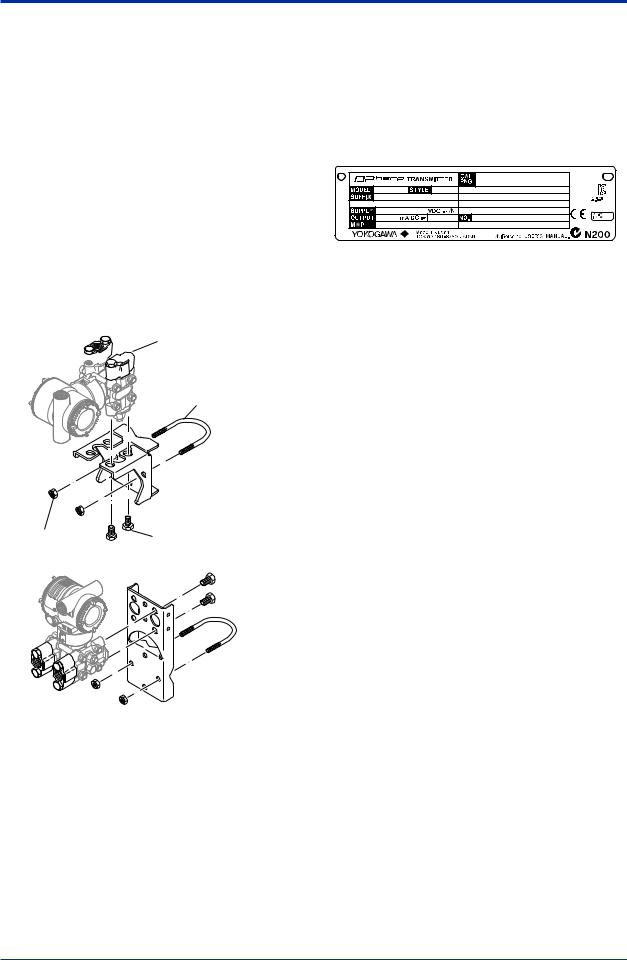
Also check that all transmitter mounting hardware shown in figure 2.1 is included. If the transmitter is ordered without the mounting bracket and the process connector, the transmitter mounting hardware will not be included.After checking the transmitter, carefully repack it in its box and keep it there until you are ready to install it.
Bolt


 Process connector (Note 1)


 Process connector
Gasket
U-bolt
 Mounting bracket (L type)
|
U-bolt nut |
Transmitter mounting bolt |
 Mounting bracket (Flat type)
F0201.ai
Figure 2.1 Transmitter Mounting Hardware
2.1Model and Specifications Check
The model name and specifications are written on the name plate attached to the case.
F0202.ai
Figure 2.2 Name Plate (EJX110A)
2.2Unpacking
Keep the transmitter in its original packaging to prevent it from being damaged during shipment. Do not unpack the transmitter until it reaches the installation site.
2.3Storage
The following precautions must be observed when storing the instrument, especially for a long period.
(a)Select a storage area which meets the following conditions:
•It is not exposed to rain or subject to water seepage/leaks.
•Vibration and shock are kept to a minimum.
•It has an ambient temperature and relative humidity within the following ranges.
Ambient temperature:
–40* to 85°C without integral indicator
–30* to 80°C with integral indicator
* –15°C when /HE is specified.
Relative humidity: 0% to 100% R.H.
Preferred temperature and humidity: approx. 25°C and 65% R.H.
(b)When storing the transmitter, repack it carefully in the packaging that it was originally shipped with.
(c)If the transmitter has been used, thoroughly clean the chambers inside the cover flanges, so that there is no process fluid remaining inside. Before placing it in storage, also make sure that the pressure-detector is securely connected to the transmitter section.
IM 01C25B01-01E

|
<2. Handling Cautions> |
2-2 |
2.4Selecting the Installation Location
The transmitter is designed to withstand severe environmental conditions. However, to ensure that it will provide years of stable and accurate performance, take the following precautions when selecting the installation location.
(a)Ambient Temperature
Avoid locations subject to wide temperature variations or a significant temperature gradient. If the location is exposed to radiant heat from plant equipment, provide adequate thermal insulation and/or ventilation.
(b)AmbientAtmosphere
Do not install the transmitter in a corrosive atmosphere. If this cannot be avoided, there must be adequate ventilation as well as measures to prevent the leaking of rain water and the presence of standing water in the conduits.
(c)Shock and Vibration
Although the transmitter is designed to be relatively resistant to shock and vibration, an installation site should be selected where this is kept to a minimum.
(d)Installation of Explosion-protected Transmitters An explosion-protected transmitters is certified for installation in a hazardous area containing specific gas types. See subsection 2.9 “Installation of an Explosion-Protected Transmitters.”
2.5Pressure Connection
 WARNING
•Never loosen the process connector bolts when an instrument is installed in a process. The device is under pressure, and a loss of seal can result in a sudden and uncontrolled release of process fluid.
•When draining toxic process fluids that have condensed inside the pressure detector, take appropriate steps to prevent the contact of such fluids with the skin or eyes and the inhalation of vapors from these fluids.
The following precautions must be observed in order to safely operate the transmitter under pressure.
(a)Make sure that all the process connector bolts are tightened firmly.
(b)Make sure that there are no leaks in the impulse piping.
(c)Never apply a pressure higher than the specified maximum working pressure.
2.6Waterproofing of Cable Conduit Connections
Apply a non-hardening sealant to the threads to waterproof the transmitter cable conduit connections. (See figure 6.8, 6.9 and 6.10.)
2.7Restrictions on Use of Radio Transceivers
 IMPORTANT
Although the transmitter has been designed to resist high frequency electrical noise, if a radio transceiver is used near the transmitter or its external wiring, the transmitter may be affected by high frequency noise pickup. To test this, start out from a distance of several meters and slowly approach the transmitter with the transceiver while observing the measurement loop for noise effects. Thereafter use the transceiver outside the range where the noise effects were first observed.
2.8Insulation Resistance and Dielectric Strength Test
Since the transmitter has undergone insulation resistance and dielectric strength tests at the factory before shipment, normally these tests are not required. If the need arises to conduct these tests, heed the following:
(a)Do not perform such tests more frequently than is absolutely necessary. Even test voltages that do not cause visible damage to the insulation may degrade the insulation and reduce safety margins.
IM 01C25B01-01E
![]()
|
<2. Handling Cautions> |
2-3 |
(b)Never apply a voltage exceeding 500 V DC (100 V DC with an internal lightning protector) for the insulation resistance test, nor a voltage exceeding 500 VAC (100 VAC with an internal lightning protector) for the dielectric strength test.
(c)Before conducting these tests, disconnect all signal lines from the transmitter terminals. The procedure for conducting these tests is as follows:
•Insulation Resistance Test
1)Short-circuit the + and – SUPPLY terminals in the terminal box.
2)Turn OFF the insulation tester. Then connect the insulation tester plus (+) lead wire to the shorted SUPPLY terminals and the minus (–) leadwire to the grounding terminal.
3)Turn ON the insulation tester power and measure the insulation resistance. The voltage should be applied as briefly as possible to verify that the insulation resistance is at least 20 MΩ.
4)After completing the test and being very careful not to touch exposed conductors disconnect the insulation tester and connect a 100 kΩ resistor between the grounding terminal and the shortcircuiting SUPPLY terminals. Leave this resistor connected at least one second to discharge any static potential. Do not touch the terminals while it is discharging.
•Dielectric Strength Test
1)Short-circuit the + and – SUPPLY terminals in the terminal box.
2)Turn OFF the dielectric strength tester. Then connect the tester between the shorted SUPPLY terminals and the grounding terminal. Be sure to connect the grounding lead of the dielectric strength tester to the ground terminal.
3)Set the current limit on the dielectric strength tester to 10 mA, then turn ON the power and gradually increase the test voltage from ‘0’to the specified voltage.
4)When the specified voltage is reached, hold it for one minute.
5)After completing this test, slowly decrease the voltage to avoid any voltage surges.
2.9Installation of an ExplosionProtected Instrument
 NOTE
NOTE
For FOUNDATION Fieldbus explosion protected type, please refer to IM 01C22T02-01E.
For PROFIBUS PAexplosion protected type, please refer to IM 01C25T04-01EN.
If a customer makes a repair or modification to an intrinsically safe or explosionproof instrument and the instrument is not restored to its original condition, its intrinsically safe or explosionproof construction may be compromised and the instrument may be hazardous to operate. Please contact Yokogawa before making any repair or modification to an instrument.
 CAUTION
This instrument has been tested and certified as being intrinsically safe or explosionproof. Please note that severe restrictions apply to this instrument’s construction, installation, external wiring, maintenance and repair.Afailure to abide by these restrictions could make the instrument a hazard to operate.
 WARNING
Maintaining the safety of explosionproof equipment requires great care during mounting, wiring, and piping. Safety requirements also place restrictions on maintenance and repair. Please read the following sections very carefully.
 WARNING
The range setting switch must not be used in a hazardous area.
IM 01C25B01-01E

|
<2. Handling Cautions> |
2-4 |
 IMPORTANT
For combined approval types
Once a device of multiple approval type is installed, it should not be re-installed using any other approval types.Apply a permanent mark in the check box of the selected approval type on the certification label on the transmitter to distinguish it from unused approval types.
 IMPORTANT
All the blind plugs which accompany the EJX/ EJA-E transmitters upon shipment from the factory are certified by the applicable agency in combination with those transmitters. The plugs which are marked with the symbols “◊ Ex” on their surfaces are certified only in combination with the EJX/EJA-E series transmitters.
2.9.1 FMApproval
a.FM Intrinsically Safe Type
Caution for FM intrinsically safe type. (Following contents refer “DOC. No. IFM022-A12”)
Note 1. Model EJX/EJA-E Series Differential, gauge and absolute pressure transmitters with optional code /FS1 are applicable for use in hazardous locations.
•Applicable Standard: FM3600, FM3610, FM3611, FM3810
•Intrinsically Safe for Class I, Division 1, GroupsA, B, C & D. Class II, Division 1, Groups E, F & G and Class III, Division 1, Class I, Zone 0 in Hazardous Locations,AEx ia IIC
•Nonincendive for Class I, Division 2, Groups A, B, C & D. Class II, Division 2, Groups F & G, Class I, Zone 2, Groups IIC, in Hazardous Locations.
•Outdoor hazardous locations, NEMATYPE 4X.
•Temperature Class: T4
•Ambient temperature: –60 to 60°C
Note 2. Entity Parameters
•Intrinsically SafeApparatus Parameters [GroupsA, B, C, D, E, F and G]
|
Vmax = 30 V |
Ci = 6 nF |
|
Imax = 200 mA |
Li = 0 µH |
|
Pmax = 1 W |
*AssociatedApparatus Parameters (FM approved barriers)
|
Voc ≤ 30 V |
Ca > 6 nF |
|
Isc ≤ 200 mA |
La > 0 µH |
|
Pmax ≤ 1W |
•Intrinsically SafeApparatus Parameters [Groups C, D, E, F and G]
|
Vmax = 30 V |
Ci = 6 nF |
|
Imax = 225 mA |
Li = 0 µH |
|
Pmax = 1 W |
*AssociatedApparatus Parameters (FM approved barriers)
|
Voc ≤ 30 V |
Ca > 6 nF |
|
Isc ≤ 225 mA |
La > 0 µH |
|
Pmax ≤ 1 W |
•Entity Installation Requirements
Vmax ≥ Voc or Uo or Vt, Imax ≥ Isc or Io or It, Pmax (or Po) ≤ Pi, Ca or Co ≥ Ci + Ccable, La or Lo ≥ Li + Lcable
Note 3. Installation
•Barrier must be installed in an enclosure that meets the requirements ofANSI/ISAS82.01.
•Control equipment connected to barrier must not use or generate more than 250 V rms or V dc.
•Installation should be in accordance with ANSI/ISARP12.6 “Installation of Intrinsically Safe Systems for Hazardous (Classified) Locations” and the National Electric Code (ANSI/NFPA70).
•The configuration of associated apparatus must be FMRCApproved.
•Dust-tight conduit seal must be used when installed in a Class II, III, Group E, F and G environments.
•Associated apparatus manufacturer’s installation drawing must be followed when installing this apparatus.
•The maximum power delivered from the barrier must not exceed 1 W.
•Note a warning label worded “SUBSTITUTION OF COMPONENTS MAY IMPAIR INTRINSIC SAFETY,” and “INSTALL INACCORDANCE WITH DOC. No. IFM022A12”
IM 01C25B01-01E
|
<2. Handling Cautions> |
2-5 |
Note 4. Maintenance and Repair
•The instrument modification or parts replacement by other than authorized representative of Yokogawa Electric Corporation is prohibited and will void Factory Mutual Intrinsically safe and NonincendiveApproval.
[Intrinsically Safe]
Hazardous Location 
 Nonhazardous Location
|
Class I, II, III, Division 1, |
||||||||||||||||||||
|
Groups A, B, C, D, E, F, G |
||||||||||||||||||||
|
Class 1, Zone 0 in |
||||||||||||||||||||
|
Hazardous (Classified) |
General |
|||||||||||||||||||
|
Locations AEx ia IIC |
||||||||||||||||||||
|
Purpose |
||||||||||||||||||||
|
Pressure Transmitters |
Safety Barrier |
Equipment |
||||||||||||||||||
|
+ |
+ |
+ |
+ |
|||||||||||||||||
|
Supply |
– |
– |
– |
– |
||||||||||||||||
|
F0203-1.ai |
||||||||||||||||||||
|
[Nonincendive] |
||||||||||||||||||||
|
Hazardous Location |
Nonhazardous Location |
|||||||||||||||||||
|
Class I, II, Division 2, |
||||||||||||||||||||
|
Groups A, B, C, D, F, G |
||||||||||||||||||||
|
Class 1, Zone 2, Group IIC, |
||||||||||||||||||||
|
in Hazardous (Classified) |
General |
|||||||||||||||||||
|
Locations |
||||||||||||||||||||
|
Purpose |
||||||||||||||||||||
|
Pressure Transmitters |
Equipment |
|||||||||||||||||||
|
Supply |
+ |
+ |
||||||||||||||||||
|
– |
– |
|||||||||||||||||||
|
Not Use |
||||||||||||||||||||
|
Safety Barrier |
F0203-2.ai |
|||||||||||||||||||
b. FM Explosionproof Type
Caution for FM explosionproof type.
Note 1. Model EJX/EJA-E Series pressure transmitters with optional code /FF1 are applicable for use in hazardous locations.
•Applicable Standard: FM3600, FM3615, FM3810,ANSI/NEMA250
•Explosionproof for Class I, Division 1, Groups B, C and D.
•Dust-ignitionproof for Class II/III, Division 1, Groups E, F and G.
•Enclosure rating: NEMATYPE 4X.
•Temperature Class: T6
•Ambient Temperature: –40 to 60°C
•Supply Voltage: 42 V dc max.
•Output signal: 4 to 20 mA
Note 2. Wiring
•All wiring shall comply with National Electrical CodeANSI/NFPA70 and Local Electrical Codes.
•When installed in Division 1, “FACTORY SEALED, CONDUIT SEALNOT REQUIRED.”
Note 3. Operation
•Keep the “WARNING” nameplate attached to the transmitter.
WARNING: OPEN CIRCUIT BEFORE REMOVING COVER. FACTORY SEALED, CONDUIT SEALNOT REQUIRED. INSTALLINACCORDANCE WITH THE USERS MANUAL IM 01C25.
•Take care not to generate mechanical sparking when accessing to the instrument and peripheral devices in a hazardous location.
Note 4. Maintenance and Repair
•The instrument modification or parts replacement by other than authorized representative of Yokogawa Electric Corporation is prohibited and will void Factory Mutual ExplosionproofApproval.
c.FM Intrinsically Safe Type/FM Explosionproof Type
Model EJX/EJA-E Series pressure transmitters with optional code /FU1 or /V1U1 can be selected the type of protection (FM Intrinsically Safe or FM Explosionproof) for use in hazardous locations.
Note 1. For the installation of this transmitter, once a particular type of protection is selected, any other type of protection cannot be used. The installation must be in accordance with the description about the type of protection in this instruction manual.
Note 2. In order to avoid confusion, unnecessary marking is crossed out on the label other than the selected type of protection when the transmitter is installed.
IM 01C25B01-01E
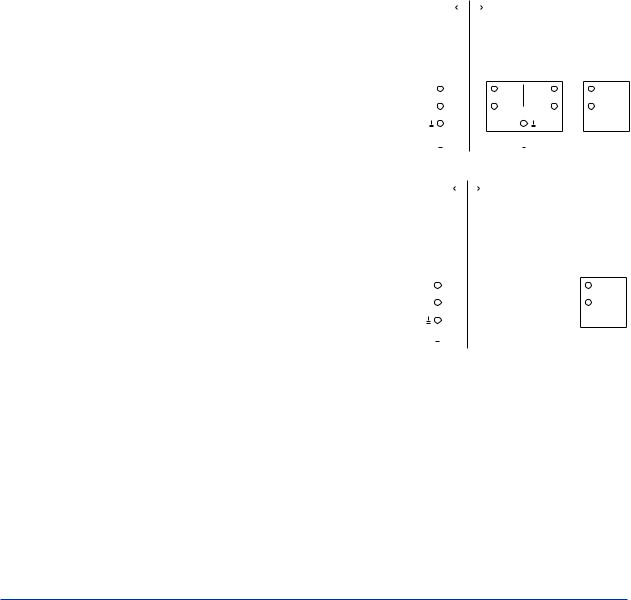
|
<2. Handling Cautions> |
2-6 |
2.9.2 CSACertification
a.CSAIntrinsically Safe Type
Caution for CSAIntrinsically safe and nonincendive type. (Following contents refer to “DOC No. ICS013-A13”)
Note 1. Model EJX/EJA-E Series differential, gauge, and absolute pressure transmitters with optional code /CS1 are applicable for use in hazardous locations
Certificate: 1606623 [For CSAC22.2]
•Applicable Standard: C22.2 No.0, C22.2 No.0.4, C22.2 No.25, C22.2 No.94, C22.2 No.157, C22.2 No.213, C22.2 No.61010-1, C22.2 No.60079-0
•Intrinsically Safe for Class I, Division 1, GroupsA, B, C & D, Class II, Division 1, Groups E, F & G, Class III, Division 1
•Nonincendive for Class I, Division 2, Groups A, B, C & D, Class II, Division 2, Groups E, F & G, Class III, Division 1
•Enclosure: NEMATYPE 4X
•Temp. Code: T4
•Amb. Temp.:–50* to 60°C
*–15°C when /HE is specified.
•Process Temperature: 120°C max. [For CSAE60079]
•Applicable Standard: CAN/CSAE60079-11, CAN/CSAE60079-15, IEC 60529:2001
•Ex ia IIC T4, Ex nLIIC T4
•Ambient Temperature: –50* to 60°C
*–15°C when /HE is specified.
•Max. Process Temp.: 120°C
•Enclosure: IP66/IP67
Note 2. Entity Parameters
•Intrinsically safe ratings are as follows: Maximum Input Voltage (Vmax/Ui) = 30 V Maximum Input Current (Imax/Ii) = 200 mA Maximum Input Power (Pmax/Pi) = 0.9 W Maximum Internal Capacitance (Ci) = 10 nF Maximum Internal Inductance (Li) = 0 µH
•Type «n» or Nonincendive ratings are as follows:
Maximum Input Voltage (Vmax/Ui) = 30 V Maximum Internal Capacitance (Ci) = 10 nF Maximum Internal Inductance (Li) = 0 µH
•Installation Requirements Uo ≤ Ui, Io ≤ Ii, Po ≤ Pi,
Co ≥ Ci + Ccable, Lo ≥ Li + Lcable Voc ≤ Vmax, Isc ≤ Imax,
Ca ≥ Ci + Ccable, La ≥ Li + Lcable
Uo, Io, Po, Co, Lo, Voc, Isc, Ca and La are parameters of barrier.
Note 3. Installation
•In any safety barreir used output current must be limited by a resistor ‘R’ such that Io=Uo/R or Isc=Voc/R.
•The safety barrier must be CSAcertified.
•Input voltage of the safety barrier must be less than 250 Vrms/Vdc.
•Installation should be in accordance with Canadian Electrical Code Part I and Local Electrical Code.
•Dust-tight conduit seal must be used when installed in Class II and III environments.
•The instrument modification or parts replacement by other than authorized representative of Yokogawa Electric Corporation and Yokogawa Corporation ofAmerica is prohibited and will void Canadian Standards Intrinsically safe and nonincendive Certification.
|
[Intrinsically Safe] |
|||||||||||||||||||||||||
|
Hazardous Location |
Nonhazardous Location |
||||||||||||||||||||||||
|
Group IIC, Zone 0 |
|||||||||||||||||||||||||
|
Class I, II, III, Division 1, |
General |
||||||||||||||||||||||||
|
Groups A, B, C, D, E, F, G |
|||||||||||||||||||||||||
|
Purpose |
|||||||||||||||||||||||||
|
Safety Barrier |
|||||||||||||||||||||||||
|
Pressure Transmitters |
Equipment |
||||||||||||||||||||||||
|
+ |
+ |
+ |
+ |
||||||||||||||||||||||
|
Supply |
– |
– |
– |
– |
|||||||||||||||||||||
|
F0204-1.ai |
|||||||||||||||||||||||||
|
[Nonincendive] |
|||||||||||||||||||||||||
|
Hazardous Location |
Nonhazardous Location |
||||||||||||||||||||||||
|
Group IIC, Zone 2 |
|||||||||||||||||||||||||
|
Class I, II, Division 2, |
CSA Certified |
||||||||||||||||||||||||
|
Groups A, B, C, D, F, G |
|||||||||||||||||||||||||
|
Equipment |
|||||||||||||||||||||||||
|
Class III, Division 1. |
|||||||||||||||||||||||||
|
([nL] or |
|||||||||||||||||||||||||
|
Pressure Transmitters |
|||||||||||||||||||||||||
|
nonincendive) |
|||||||||||||||||||||||||
|
+ |
|||||||||||||||||||||||||
|
Supply |
+ |
||||||||||||||||||||||||
|
– |
– |
||||||||||||||||||||||||
|
Not Use |
|||||||||||||||||||||||||
|
Safety Barrier |
F0204-2.ai |
||||||||||||||||||||||||
b. CSAExplosionproof Type
Caution for CSAexplosionproof type.
Note 1. Model EJX/EJA-E Series pressure transmitters with optional code /CF1 are applicable for use in hazardous locations:
•Certificate: 2014354
•Applicable Standard: C22.2 No.0,
C22.2 No.0.4, C22.2 No.0.5, C22.2 No.25,
C22.2 No.30, C22.2 No.94,
C22.2 No.61010-1, C22.2 No.60079-0,
C22.2 No.60079-1
IM 01C25B01-01E
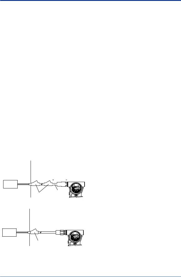
•Explosion-proof for Class I, Groups B, C and D.
•Dustignition-proof for Class II/III, Groups E, F and G.
•Enclosure: NEMATYPE 4X
•Temperature Code: T6…T4
•Ex d IIC T6…T4
•Enclosure: IP66/IP67
•Maximum Process Temperature: 120°C (T4), 100°C (T5), 85°C (T6)
•Ambient Temperature: –50* to 75°C (T4),
–50* to 80°C (T5), –50* to 75°C (T6)
* –15°C when /HE is specified.
•Supply Voltage: 42 V dc max.
•Output Signal: 4 to 20 mAdc
Note 2. Wiring
•All wiring shall comply with Canadian Electrical Code Part I and Local Electrical Codes.
•In hazardous location, wiring shall be in conduit as shown in the figure.
•WARNING:
ASEALSHALLBE INSTALLED WITHIN 50cm OF THE ENCLOSURE.
UN SCELLEMENT DOIT ÊTRE INSTALLÉ À MOINS DE 50cm DU BOÎTIER.
•WARNING:
WHEN INSTALLED IN CL.I, DIV 2, SEAL NOT REQUIRED.
UNE FOIS INSTALLÉ DANS CLI, DIV 2, AUCUN JOINT N’EST REQUIS.
|
Non-Hazardous |
Hazardous Locations Division 1 |
|||||||||
|
Locations |
||||||||||
|
Non-hazardous |
||||||||||
|
Location |
50 cm Max. |
|||||||||
|
Equipment |
||||||||||
|
42 V DC Max. |
SUPPLY |
||
|
Sealing Fitting |
Conduit |
||
|
4 to 20 mA DC |
|||
|
Signal |
Transmitter |
||
|
F0205-1.ai |
Non-Hazardous Hazardous Locations Division 2
Locations
Non-hazardous
Location
Equipment
|
42 V DC Max. |
SUPPLY |
|
4 to 20 mA DC |
Sealing Fitting |
|
Signal |
Transmitter |
|
F0205-2.ai |
|
<2. Handling Cautions> |
2-7 |
•All wiring shall comply with local installation requirements and local electrical code.
•In hazardous locations, the cable entry devices shall be of a certified flameproof type, suitable for the conditions of use and correctly installed.
•Unused apertures shall be closed with suitable flameproof certified blanking elements. (The plug attached is flameproof certified.)
Note 3. Operation
•WARNING:
AFTER DE-ENERGIZING, DELAY 5 MINUTES BEFORE OPENING. APRÉS POWER-OFF,ATTENDRE 5 MINUTESAVANT D’OUVRIR.
•WARNING:
WHENAMBIENTTEMPERATURE ≥ 65°C, USE THE HEAT-RESISTING CABLES ≥ 90°C.
QUAND LATEMPÉRATUREAMBIANTE ≥ 65°C, UTILISEZ DES CÂBLES RÉSISTANTES Á LACHALEUR ≥ 90°C.
•Take care not to generate mechanical sparking when accessing to the instrument and peripheral devices in a hazardous location.
Note 4. Maintenance and Repair
•The instrument modification or parts replacement by other than authorized representative of Yokogawa Electric Corporation and Yokogawa Corporation of America is prohibited and will void Canadian Standards Explosionproof Certification.
cCSAIntrinsically Safe Type/CSA Explosionproof Type
Model EJX/EJA-E Series pressure transmitters with optional code /CU1 or /V1U1 can be selected the type of protection (CSAIntrinsically Safe or CSAExplosionproof) for use in hazardous locations.
Note 1. For the installation of this transmitter, once a particular type of protection is selected, any other type of protection cannot be used. The installation must be in accordance with the description about the type of protection in this instruction manual.
Note 2. In order to avoid confusion, unnecessary marking is crossed out on the label other than the selected type of protection when the transmitter is installed.
IM 01C25B01-01E
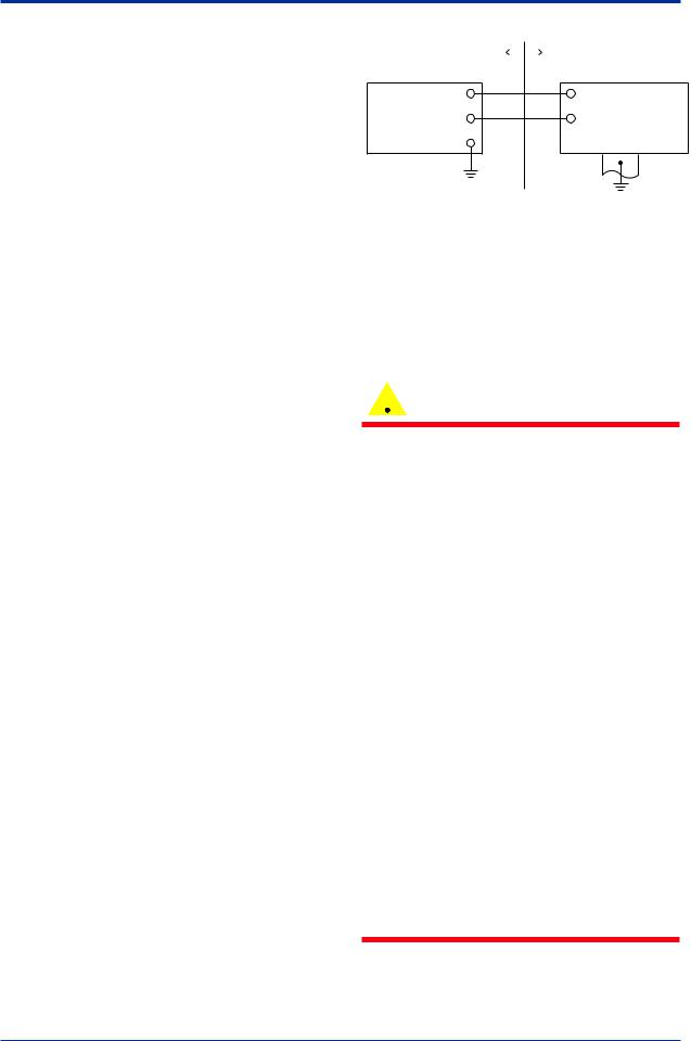
2.9.3 ATEX Certification
(1) Technical Data
a. ATEX Intrinsically Safe Ex ia
Caution forATEX Intrinsically safe type.
Note 1. Model EJX/EJA-E Series pressure transmitters with optional code /KS21 for potentially explosive atmospheres:
•No. DEKRA11ATEX0228 X
•Applicable Standard:
EN 60079-0:2009, EN 60079-11:2007, EN 60079-26:2007, EN 61241-11:2006
•Type of Protection and Marking code: Ex ia IIC T4 Ga
Ex ia IIIC T85 ºC T100 ºC T120 ºC Db
•Group: II
•Category: 1G, 2D
•Ambient Temperature for EPLGa: –50 to 60°C
•Ambient Temperature for EPLDb: –30* to 60°C
* –15°C when /HE is specified.
•Process Temperature (Tp.): 120°C max.
•Maximum Surface Temperature for EPLDb: T85°C (Tp.: 80°C)
T100°C (Tp.: 100°C) T120°C (Tp.: 120°C)
•Enclosure: IP66 / IP67
Note 2 Electrical Data
•In type of explosion protection intrinsic safety Ex ia IIC or Ex ia IIIC, only for connection to a certified intrinsically safe circuit with following maximum values:
Ui = 30 V Ii = 200 mA Pi = 0.9 W
(Linear Source)
Maximum internal capacitance; Ci = 27.6 nF Maximum internal inductance; Li = 0 µH
Note 3. Installation
•Refer to the control drawing.All wiring shall comply with local installation requirements.
|
<2. Handling Cautions> |
2-8 |
||||
|
[Control Drawing] |
|||||
|
Hazardous Location |
Nonhazardous Location |
||||
|
Transmitter |
|
|
+ |
+ |
|
Supply |
Safety Barrier *1 |
|
– |
– |
F0206.ai
*1: In any safety barriers used the output current must be limited by a resistor “R” such that Io=Uz/R.
Note 4. Maintenance and Repair
•The instrument modification or parts replacement by other than authorized representative of Yokogawa Electric Corporation is prohibited and will void DEKRAIntrinsically safe Certification.
Note 5. Special Conditions for Safe Use
 WARNING
•In the case where the enclosure of the Pressure Transmitter is made of aluminium, if it is mounted in an area where the use of category 1 G apparatus is required, it must be installed such, that, even in the event of rare incidents, ignition sources due to impact and friction sparks are excluded.
•Electrostatic charge may cause an exlosion hazard. Avoid any actions that cause the gerenation of eletrostatic charge, such as rubbing with a dry cloth on coating face of the product.
•In case of the enclosure of the Pressure Transmitter with paint layers, if it is mounted in an area where the use of category 2D apparatus is required, it shall be installed in such a way that the risk from electrostatic discharges and propagating brush discharges caused by rapid flow of dust is avoided.
•To satisfy IP66 or IP67, apply waterproof glands to the electrical connection port.
•When the lightning protector option is specified, the apparatus is not capable of withstanding the 500V insulation test
required by EN60079-11. This must be taken
into account when installing the apparatus.
IM 01C25B01-01E

|
<2. Handling Cautions> |
2-9 |
b. ATEX Flameproof Type
Caution forATEX flameproof type.
Note 1. Model EJX/EJA-E Series pressure transmitters with optional code /KF22 for potentially explosive atmospheres:
•No. KEMA07ATEX0109 X
•Applicable Standard: EN 60079-0:2009, EN 60079-1:2007, EN 60079-31:2009
•Type of Protection and Marking Code:
Ex d IIC T6…T4 Gb, Ex tb IIIC T85°C Db
•Group: II
•Category: 2G, 2D
•Enclosure: IP66 / IP67
•Temperature Class for gas-poof: T6, T5, and T4
•Ambient Temperature for gas-proof: –50 to 75°C (T6), –50 to 80°C (T5), and –50 to 75°C (T4)
•Maximum Process Temperature (Tp.) for gas-proof:
85°C (T6), 100°C (T5), and 120°C (T4)
•Maximum Surface Temperature for dustproof:
T85°C (Tamb.: –30* to 75°C, Tp.: 85°C)
* –15°C when /HE is specified.
Note 2. Electrical Data
•Supply voltage: 42 V dc max.
•Output signal: 4 to 20 mA
Note 3. Installation
•All wiring shall comply with local installation requirement.
•The cable entry devices shall be of a certified flameproof type, suitable for the conditions of use.
Note 4. Operation
•Keep the “WARNING” label attached to the transmitter.
WARNING:AFTER DE-ENERGIZING, DELAY 5 MINUTES BEFORE OPENING. WHEN THEAMBIENTTEMP.≥65°C, USE HEAT-RESISTING CABLEAND CABLE GLAND ≥90°C.
•Take care not to generate mechanical sparking when accessing to the instrument and peripheral devices in a hazardous location.
Note 5. Special Conditions for Safe Use
 WARNING
•Electrostatic charge may cause an exlosion hazard. Avoid any actions that cause the gerenation of eletrostatic charge, such as rubbing with a dry cloth on coating face of the product.
•In the case where the enclosure of the Pressure Transmitter is made of aluminium, if it is mounted in an area where the use of category 2D apparatus is required, it shall be installed in such a way that the risk from electrostatic discharges and propagating brush discharges caused by rapid flow of dust is avoided.
•The instrument modification or parts replacement by other than an authorized Representative of Yokogawa Electric Corporation is prohibited and will void the certification.
•To satisfy IP66 or IP67, apply waterproof glands to the electrical connection port.
c.ATEX Intrinsically Safe Type/ATEX Flameproof Type
Model EJX/EJA-E Series pressure transmitters with optional code /KU22 or /V1U1 can
be selected the type of protectionATEX Flameproof, Intrinsically Safe. Ex ia, or Ex ic for use in hazardous area.
Note 1. For the installation of this transmitter, once a particular type of protection is selected, any other type of protection cannot be used. The installation must be in accordance with the description about the type of protection in this user’s manual.
Note 2. For combined approval types Once a device of multiple approval type is installed, it should not be re-installed using any other approval types.Apply a permanent mark in the check box of the selected approval type on the certification label on the transmitter to distinguish it from unused approval types.
IM 01C25B01-01E
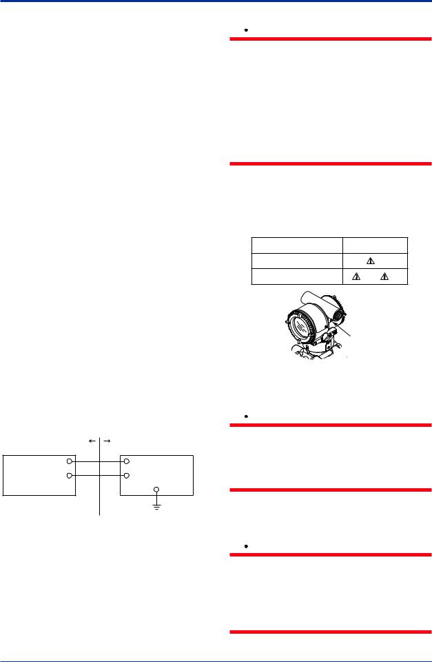
● ATEX Intrinsically Safe Ex ic
Caution forATEX intrinsically safe Ex ic
•Applicable Standard:
EN 60079-0:2009/EN 60079-0:2012, EN 60079-11:2012
•Type of Protection and Marking Code:  II 3G Ex ic IIC T4 Gc
•Ambient Temperature: –30* to +60°C
* –15°C when /HE is specified.
•Ambient Humidity:
0 to 100% (No condensation)
•Maximum Process Temperature: 120°C
•IP Code: IP66
•Ambient pollution degree: 2
•Overvoltage category: I
Note 1. Electrical Data
Ui = 30 V
Ci = 27.6 nF
Li = 0 µH
Note 2. Installation
•All wiring shall comply with local installation requirements. (refer to the control drawing)
•Cable glands, adapters and/or blanking elements shall be of Ex “n”, Ex “e” or Ex “d” and shall be installed so as to maintain the specified degree of protection (IP Code) of the transmitters.
Note 3. Maintenance and Repair
•The instrument modification or parts replacement by other than authorized representative of Yokogawa Electric Corporation is prohibited and will voidATEX intrinsically safe.
|
[Control drawing] |
|||
|
Hazardous Area |
Nonhazardous Area |
||
|
+ |
Associated |
||
|
Transmitter |
– |
||
|
Apparatus |
|||
F0207.ai
Note 4. Specific Conditions of Use
|
<2. Handling Cautions> |
2-10 |
 WARNING
•Electrostatic charge may cause an explosion hazard. Avoid any actions that cause the gerenation of eletrostatic charge, such as rubbing with a dry cloth on coating face of the product.
•When the lightning protector option is specified, the apparatus is not capable of withstanding the 500V insulation test
required by EN60079-11. This must be taken into account when installing the apparatus.
(2)Electrical Connection
Amark indicating the electrical connection type is stamped near the electrical connection port. These marks are as followed.
|
Screw Size |
Marking |
|
ISO M20 × 1.5 female |
M |
|
ANSI 1/2 NPT female |
N or W |
Location of the mark
F0208.ai
(3) Installation
 WARNING
•All wiring shall comply with local installation requirements and the local electrical code.
•There is no need for conduit seal in Division 1 and Division 2 hazardous locations because this product is sealed at the factory.
(4)Operation
 WARNING
•OPEN CIRCUIT BEFORE REMOVING COVER. INSTALLINACCORDANCE WITH THIS USER’S MANUAL
•Take care not to generate mechanical sparking when access to the instrument and peripheral devices in a hazardous location.
IM 01C25B01-01E
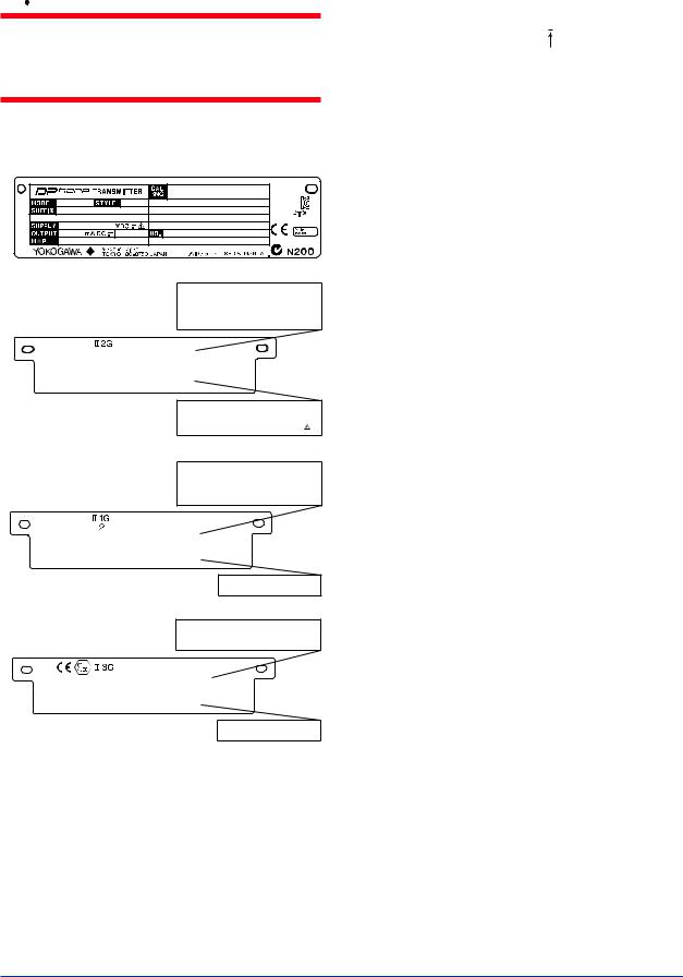
|
<2. Handling Cautions> |
2-11 |
(5) Maintenance and Repair
 WARNING
The instrument modification or parts replacement by other than an authorized Representative of Yokogawa Electric Corporation is prohibited and will void the certification.
(6) Name Plate
Name plate
Tag plate for flameproof type
|
No. KEMA 07ATEX0109 X |
||||
|
Ex d IIC T6…T4 Gb, |
Ex tb IIIC T85°C Db |
|||
|
Enlcosure : IP66/IP67 |
T6 |
T5 |
T4 |
|
|
TEMP. CLASS |
||||
|
MAX PROCESS TEMP.(Tp.) |
85 |
100 |
120 °C |
|
|
Tamb. |
-50 to |
75 |
80 |
75 °C |
T85°C(Tamb.:-30(-15) to 75°C, Tp.:85°C)(for Dust)
*3
 D
D
WARNING
AFTER DE-ENERGIZING, DELAY 5 MINUTES BEFORE
OPENING.
WHEN THE AMBIENT TEMP. ≥ 65°C, USE THE
HEAT-RESISTING CABLE & CABLE GLAND ≥ 90°C
POTENTIAL ELECTROSTATIC CHARGING HAZARD
Tag plate for intrinsically safe type
No. DEKRA 11ATEX 0228 X
Ex ia IIC T4 Ga Ta: -50 TO 60°C
|
Ex ia IIIC T85°C T100°C T120°C Db Ta:-30(-15) TO 60°C |
|
|
IP66/IP67 |
120°C |
|
MAX. PROCESS TEMP.(Tp.) |
|
|
T85°C(Tp.:80°C), T100°C(Tp.:100°C), T120°C(Tp.:120°C) |
|
|
Ui=30V, Ii=200mA , Pi=0.9W, |
Ci=27.6nF, Li=0µH |
*3
 D
D
WARNING
POTENTIAL ELECTROSTATIC CHARGING HAZARD
— SEE USER’S MANUAL
Tag plate for intrinsically safe Ex ic
Ex ic IIC T4 Gc
IP66
Tamb -30(-15) TO 60°C
MAX. PROCESS TEMP. 120°C
Ui=30V, Ci=27.6nF, Li=0µH
WARNING
POTENTIAL ELECTROSTATIC CHARGING HAZARD
— SEE USER’S MANUAL
F0209.ai
MODEL: Specified model code.
STYLE: Style code.
SUFFIX: Specified suffix code.
SUPPLY: Supply voltage.
OUTPUT: Output signal.
MWP: Maximum working pressure.
CALRNG: Specified calibration range.
NO.: Serial number and year of production*1.
TOKYO 180-8750 JAPAN:
The manufacturer name and the address*2.
*1: The first digit in the three numbers next to the nine letters of the serial number appearing after “NO.” on the nameplate indicates the year of production. The following is an example of a serial number for a product that was produced in 2010:
91K819857 032
The year 2010
*2: “180-8750” is a zip code which represents the following address.
2-9-32 Nakacho, Musashino-shi, Tokyo Japan
*3: The identification number of Notified Body.
2.9.4 IECEx Certification
Model EJX Series pressure transmitters with optional code /SU2 can be selected the type of protection (IECEx Intrinsically Safe/type n or flameproof) for use in hazardous locations.
Note 1. For the installation of this transmitter, once a particular type of protection is selected, any other type of protection cannot be used. The installation must be in accordance with the description about the type of protection in this instruction manual.
Note 2. In order to avoid confusion, unnecessary marking is crossed out on the label other than the selected type of protection when the transmitter is installed.
a. IECEx Intrinsically Safe Type / type n
Caution for IECEx Intrinsically safe and type n.
Note 1. Model EJX Series differential, gauge, and absolute pressure transmitters with optional code /SU2 are applicable for use in hazardous locations
•No. IECEx CSA05.0005
•Applicable Standard: IEC 60079-0:2000, IEC 60079-11:1999, IEC 60079-15:2001
•Ex ia IIC T4, Ex nLIIC T4
•Ambient Temperature: –50 to 60°C
•Max. Process Temp.: 120°C
•Enclosure: IP66/IP67
Note 2. Entity Parameters
•Intrinsically safe ratings are as follows: Maximum Input Voltage (Vmax/Ui) = 30 V Maximum Input Current (Imax/Ii) = 200 mA Maximum Input Power (Pmax/Pi) = 0.9 W Maximum Internal Capacitance (Ci) = 10 nF Maximum Internal Inductance (Li) = 0 µH
•Type «n» ratings are as follows: Maximum Input Voltage (Vmax/Ui) = 30 V
Maximum Internal Capacitance (Ci) = 10 nF Maximum Internal Inductance (Li) = 0 µH
IM 01C25B01-01E
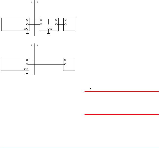
|
<2. Handling Cautions> |
2-12 |
•Installation Requirements Uo ≤ Ui, Io ≤ Ii, Po ≤ Pi,
Co ≥ Ci + Ccable, Lo ≥ Li + Lcable Voc ≤ Vmax, Isc ≤ Imax,
Ca ≥ Ci + Ccable, La ≥ Li + Lcable
Uo, Io, Po, Co, Lo, Voc, Isc, Ca and La are parameters of barrier.
Note 3. Installation
•In any safety barrier used output current must be limited by a resistor ‘R’ such that Io=Uo/R.
•The safety barrier must be IECEx certified.
•Input voltage of the safety barrier must be less than 250 Vrms/Vdc.
•The instrument modification or parts replacement by other than authorized representative of Yokogawa Electric Corporation and will void IECEx Intrinsically safe and type n certification.
|
[Intrinsically Safe] |
||||
|
Hazardous Location |
Nonhazardous Location |
|||
|
Group IIC, Zone 0 |
General |
|||
|
IECEx certified |
||||
|
Purpose |
||||
|
Pressure Transmitters |
Safety Barrier |
Equipment |
||
|
+ |
+ |
+ |
+ |
|
|
Supply |
– |
– |
– |
– |
|
F0210-1.ai |
||||
|
[type n] |
||||
|
Hazardous Location |
Nonhazardous Location |
|||
|
Group IIC, Zone 2 |
IECEx Certified |
|||
|
Pressure Transmitters |
||||
|
Equipment [nL] |
||||
|
+ |
+ |
|||
|
Supply |
– |
Not Use |
– |
|
|
Safety Barrier |
||||
|
F0210-2.ai |
b. IECEx Flameproof Type
Caution for IECEx flameproof type.
Note 1. Model EJX/EJA-E Series pressure transmitters with optional code /SF2 or /SU2 are applicable for use in hazardous locations:
•No. IECEx CSA07.0008
•Applicable Standard: IEC60079-0:2004, IEC60079-1:2003
•Flameproof for Zone 1, Ex d IIC T6…T4
•Enclosure: IP66/IP67
•Maximum Process Temperature: 120°C (T4), 100°C (T5), 85°C (T6)
•Ambient Temperature: –50 to 75°C (T4), –50 to 80°C (T5), –50 to 75°C (T6)
•Supply Voltage: 42 V dc max.
•Output Signal: 4 to 20 mAdc
Note 2. Wiring
•In hazardous locations, the cable entry devices shall be of a certified flameproof type, suitable for the conditions of use and correctly installed.
•Unused apertures shall be closed with suitable flameproof certified blanking elements.
Note 3. Operation
•WARNING:
AFTER DE-ENERGIZING, DELAY 5 MINUTES BEFORE OPENING.
•WARNING:
WHENAMBIENTTEMPERATURE ≥ 65°C, USE THE HEAT-RESISTING CABLES ≥ 90°C.
•Take care not to generate mechanical sparking when accessing to the instrument and peripheral devices in a hazardous location.
Note 4. Maintenance and Repair
•The instrument modification or parts replacement by other than authorized representative of Yokogawa Electric Corporation is prohibited and will void IECEx Certification.
2.10 EMC Conformity Standards
EN61326-1 ClassA,Table2 (For use in industrial locations)
EN61326-2-3
 CAUTION
To meet EMC regulations, Yokogawa recommends that customers run signal wiring through metal conduits or use shielded twistedpair cabling when installing EJX/EJA-E series transmitters in a plant.
IM 01C25B01-01E
![]()
|
<2. Handling Cautions> |
2-13 |
2.11Pressure Equipment Directive (PED)
(1) General
•EJX/EJA-E Series pressure transmitters are categorized as piping under the pressure accessories section of directive 97/23/EC, which corresponds toArticle 3, Paragraph 3 of PED, denoted as Sound Engineering Practice (SEP).
•EJX110A-MS, EJX110A-HS, EJX110A-VS, EJ130, EJ440, and EJA110E with /HG can be used above 200 bar and therefore considered as a part of a pressure retaining vessel where category III, Module H applies. These models with option code /PE3 conform to that category.
(2) Technical Data
•Models without /PE3
Article 3, Paragraph 3 of PED, denoted as Sound Engineering Practice (SEP).
•Models with /PE3 Module: H
Type of Equipment: PressureAccessory-Vessel Type of fluid: Liquid and Gas
Group of fluid: 1 and 2
|
Model |
Capsule |
PS*1 |
V(L) |
PS.V |
Category*2 |
|
|
code |
(bar) |
(bar.L) |
||||
|
EJA110E |
M, H, V |
160 |
0.01 |
1.6 |
||
|
EJ110 |
F, L |
Article 3, |
||||
|
EJX110A |
Paragraph 3 |
|||||
|
(SEP) |
||||||
|
EJA110E |
M, H, V |
250 |
0.01 |
2.5 |
||
|
with code |
||||||
|
/HG |
||||||
|
EJ110 |
M, H, V |
250 |
0.01 |
2.5 |
III |
|
|
with code |
||||||
|
/PE3 |
||||||
|
Article 3, |
||||||
|
EJ130 |
M, H |
500 |
0.01 |
5.0 |
Paragraph 3 |
|
|
(SEP) |
||||||
|
EJ130 |
M, H |
500 |
0.01 |
5.0 |
III |
|
|
with code |
||||||
|
/PE3 |
||||||
|
Article 3, |
||||||
|
EJ310 |
L, M,A, B |
160 |
0.01 |
1.6 |
Paragraph 3 |
|
|
(SEP) |
||||||
|
Article 3, |
||||||
|
EJ430 |
H,A, B |
160 |
0.01 |
1.6 |
Paragraph 3 |
|
|
(SEP) |
||||||
|
Article 3, |
||||||
|
EJ440 |
C, D |
500 |
0.1 |
5.0 |
Paragraph 3 |
|
|
(SEP) |
||||||
|
EJ440 |
C, D |
500 |
0.1 |
5.0 |
III |
|
|
with code |
||||||
|
/PE3 |
*1: PS is maximum pressure for vessel itself based on Pressure Equipment Directive 97/23/EC. Refer to General Specification for maximum working pressure of a transmitter.
*2: Referred to Table 1 covered byANNEX II of EC Directive on Pressure Equipment Directive 97/23/EC
(3) Operation
 CAUTION
•The temperature and pressure of fluid should be maintained at levels that are consistent with normal operating conditions.
•The ambient temperature should be maintained at a level that is consistent with normal operating conditions.
•Please take care to prevent water hammer and the like from inducing excessive pressures in pipes and valves. If phenomena are likely, install a safety valve or take some other appropriate measure to prevent pressure from exceeding PS.
•Take appropriate measures at the device or system level to protect transmitters if they are to be operated near an external heat source.
2.12 Low Voltage Directive
Applicable standard: EN61010-1
(1) Pollution Degree 2
«Pollution degree» describes the degree to which a solid, liquid, or gas which deteriorates dielectric strength or surface resistivity is adhering. » 2 » applies to normal indoor atmosphere. Normally, only non-conductive pollution occurs. Occasionally, however, temporary conductivity caused by condensation must be expected.
(2) Installation Category I
«Overvoltage category (Installation category)» describes a number which defines a transient overvoltage condition. It implies the regulation for impulse withstand voltage. » I » applies to electrical equipment which is supplied from the circuit when appropriate transient overvoltage control means (interfaces) are provided.
IM 01C25B01-01E
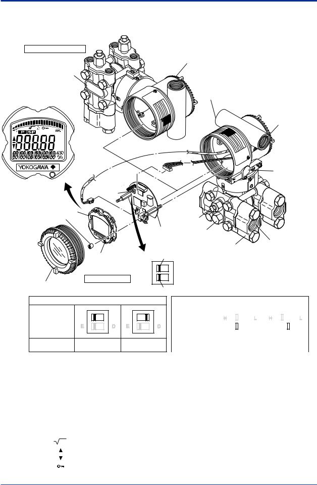
3.Component Names
Vertical impulse piping type
Pressure-detector section
Terminal box cover
Cover flange
Horizontal impulse piping type
External indicator conduit connection (Note 1)
Conduit connection
|
Zero- |
|||
|
adjustment |
|||
|
(Note 2) |
screw |
||
|
Integral |
|||
|
indicator (Note 1) |
|||
|
Mounting screw |
Vent plug |
||
|
CPU assembly Drain plug |
|||
|
Process |
Process |
||
|
connection |
|||
|
connector (Note 1) |
|||
|
Range-setting |
|||
|
Burnout direction switch |
|||
|
switch (Note 1) |
|||
|
(See section 7.6) |
BO H |
L |
|
|
Transmitter section |
WR E |
D |
|
|
Amplifier Cover |
Write protection switch |
||
Burnout direction switch (BO)
|
Burnout Direction |
H |
L |
H |
L |
|
Switch Position |
||||
|
Burnout Direction |
HIGH |
LOW |
Hardware write protection switch (WR)
|
Write Protection |
H |
L |
H |
L |
||||||||||||||||||
|
Switch Position |
E |
D |
E |
D |
||||||||||||||||||
|
Write Protection |
NO |
YES |
||||||||||||||||||||
|
(Write enabled) |
(Write disabled) |
|||||||||||||||||||||
F0301.ai
Note 1: See subsection 9.2, “Model and Suffix Codes,” for details.Aprocess connector will not be applied for lower side of EJ310,
EJ430, and EJ440.
Note 2: Applicable for BRAIN/HART communication type. Set the switches as shown in the figure above to set the burn-out direction
and write protection. The Burnout switch is set to the H side for delivery (unless option code /C1 or /C2 is specified in the order),
and the hardware write protection switch is set to E side. The setting of the switches can be confirmed via communication.An
external zero adjustment screw can only be disabled by communication. To disable the screw, set a parameter before activating
the hardware write protect function. See each communication manual.
Figure 3.1 Component Names
|
Table 3.1 |
Display Symbol |
||
|
Display Symbol |
Meaning of Display Symbol |
||
|
Display mode is ‘square root’. (Display is not lit when ‘linear’ mode.) |
|||
|
The output signal being zero-adjusted is increasing. |
|||
|
The output signal being zero-adjusted is decreasing. |
|||
|
Write protect function is enabled. |
F0302.ai
IM 01C25B01-01E
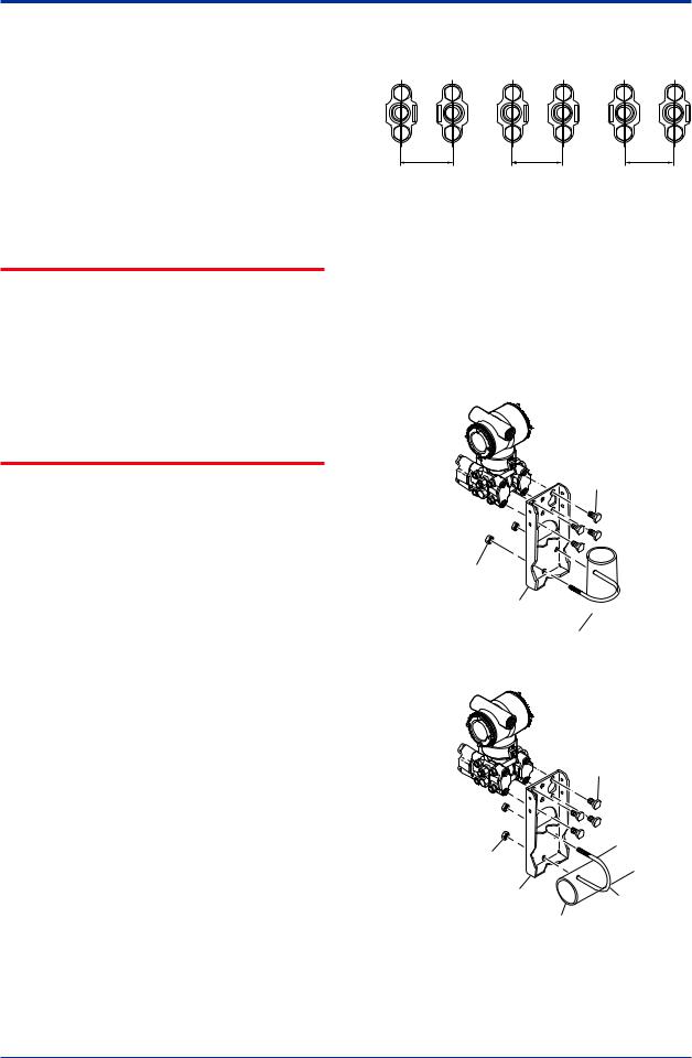
4.Installation
4.1Precautions
Before installing the transmitter, read the cautionary notes in section 2.4, “Selecting the Installation Location.” For additional information on the ambient conditions allowed at the installation location, refer to subsection 9.1 “Standard Specifications.”
 IMPORTANT
•When welding piping during construction, take care not to allow welding currents to flow through the transmitter.
•Do not step on this instrument after installation.
•For the EJ430and EJ440, the atmospheric opening is located on the low pressure side cover flange. The opening must not face upward. See section 9.4, “Dimensions,” for the location of the opening.
4.2Mounting
■The transmitter is shipped with the process connection, according to the ordering specifications. To change the orientation of the process connections, refer to section 4.3.
■With differential pressure transmitters, the distance between the impulse piping
connection ports is usually 54 mm (figure 4.1). By changing the orientation of the process connector, the dimension can be changed to 51 mm or 57 mm.
■The transmitter can be mounted on a nominal 50 mm (2-inch) pipe using the mounting bracket supplied, as shown in figure 4.2 and 4.3 The transmitter can be mounted on either a horizontal or a vertical pipe.
■When mounting the bracket on the transmitter, tighten the (four) bolts that hold the transmitter with a torque of approximately 39 N·m {4kgf·m}.
57 mm 54 mm 51 mm
F0401.ai
Figure 4.1 Process Connector Impulse Piping Connection Distances for Differential Pressure Transmitters
Figure 4.1 and 4.2 shows the mounting of the transmitter for horizontal piping and vertical piping with using the mounting bracket. The transmitters with the installation code -U (Universal flange) can be used for either type of mounting.
Vertical pipe mounting
Transmitter mounting bolt
U-bolt nut
Mounting bracket U-bolt

 50 mm(2-inch) pipe
Horizontal pipe mounting
Transmitter mounting bolt
|
U-bolt nut |
||
|
Mounting bracket |
U-bolt |
|
|
50 mm(2-inch) pipe |
F0402.ai |
|
Figure 4.2 Transmitter Mounting (Horizontal
Impulse Piping Type)
IM 01C25B01-01E
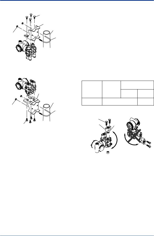
Vertical pipe mounting (Process connector downside)
Transmitter mounting bolt
Mounting bracket
50 mm(2-inch) pipe
U-bolt nut
U-bolt
Vertical pipe mounting (Process connector upside)
|
Mounting bracket |
|
|
50 mm(2-inch) pipe |
|
|
U-bolt nut |
U-bolt |
|
Transmitter |
|
|
mounting bolt |
F0403.ai |
Figure 4.3 Transmitter Mounting (Vertical Impulse
Piping Type)
4.3Changing the Process Connection
The transmitter is shipped with the process connection specified at the time of ordering. To change the process connection, the drain (vent) plug must be repositioned.
To reposition a drain (vent) plug, use a wrench to slowly and gently unscrew it. Then, remove and remount it on the opposite side. Wrap sealing tape around the drain (vent) plug threads (*1 in the figure below), and apply a lubricant to the threads of the drain (vent) screw(s) (*2 below). To tighten the drain (vent) plugs, apply a torque of 34 to 39 N·m (3.5 to 4 kgf·m). Process connector bolts are to be tightened uniformly to a torque shown in table 4.1.
|
Table 4.1 |
Torque |
|||
|
EJ110 |
EJ440 |
|||
|
Model |
EJ120 |
|||
|
EJ130 |
||||
|
EJ310 |
C capsule D capsule |
|||
|
EJ430 |
||||
|
Torque(N·m) |
39 to 49 {4 to 5} |
49 to 59 |
||
|
{kgf·m} |
{5 to 6} |
|||
|
Vertical impulse piping type |
Horizontal impulse piping type |
|||
|
Bolt |
||||
|
Process |
gasket |
|||
|
connector |
||||


 *1
*1
Drain/vent plug 
 *2 Note: For a horizontal impulse piping type, moving the
process connectors from the front side to the back cannot be made.
F0404.ai
Figure 4.4 Changing Process Connection
IM 01C25B01-01E
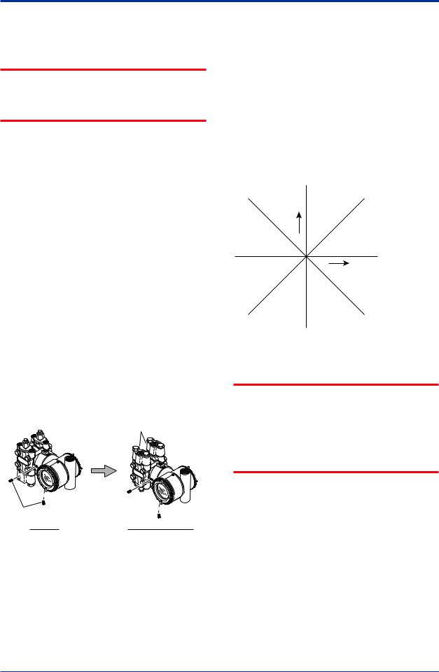
4.4Swapping the High/Lowpressure Side Connection
 IMPORTANT
This section is applicable only for EJ110, EJ120, and EJ130differential transmitters, and not applicable for gauge or absolute pressure transmitters.
4.4.1Rotating Pressure-detector Section 180°
This procedure can be applied only to a transmitter with a vertical impulse piping type.
The procedure below can be used to turn the pressure detector assembly 180°. Perform this operation in a maintenance shop with the
necessary tools laid out and ready for use, and then install the transmitter in the field after making the change.
1)Use anAllen wrench (JIS B4648, nominal 2.5 mm) to remove the two setscrews at the joint between the pressure-detector section and transmitter section.
2)Leaving the transmitter section in position, rotate the pressure-detector section 180°.
3)Tighten the two setscrews to fix the pressuredetector section and transmitter section together (at a torque of 1.5 N·m). Reposition the process connector and drain
(vent) plugs to the opposite side as described in subsection 4.3.
Process connector
|
Setscrew |
|
|
Before |
After rotating 180° |
|
F0405.ai |
Figure 4.5 Before andAfter Modification
4.4.2 Using the Communicator
This method is applicable only to the Model EJ110, EJ120, and EJ130.
With a communicator, you can change which process connection is used as the high-pressure side without mechanically rotating the pressuredetector section 180 as described in subsection 4.4.1. To change, call parameter ‘D15: H/LSWAP’ for BRAIN Communication or ‘H/Lswap’for HART Communication and select REVERSE (right side: low pressure; left side: high pressure) or select NORMALto change back to normal (right side: high pressure; left side: low pressure).
|
NORMAL |
|
Output |
|
Input |
|
REVERSE |
F0406.ai
Figure 4.6 Input/Output Relationship
 IMPORTANT
Since the H/Llabel plate on the capsule assembly will remain unchanged, use this function only when you cannot switch the impulse piping. If the ‘H/LSWAP’parameter setting is changed, the input/output relationship is reversed as shown in figure 4.6; be sure this is understood by all.
IM 01C25B01-01E
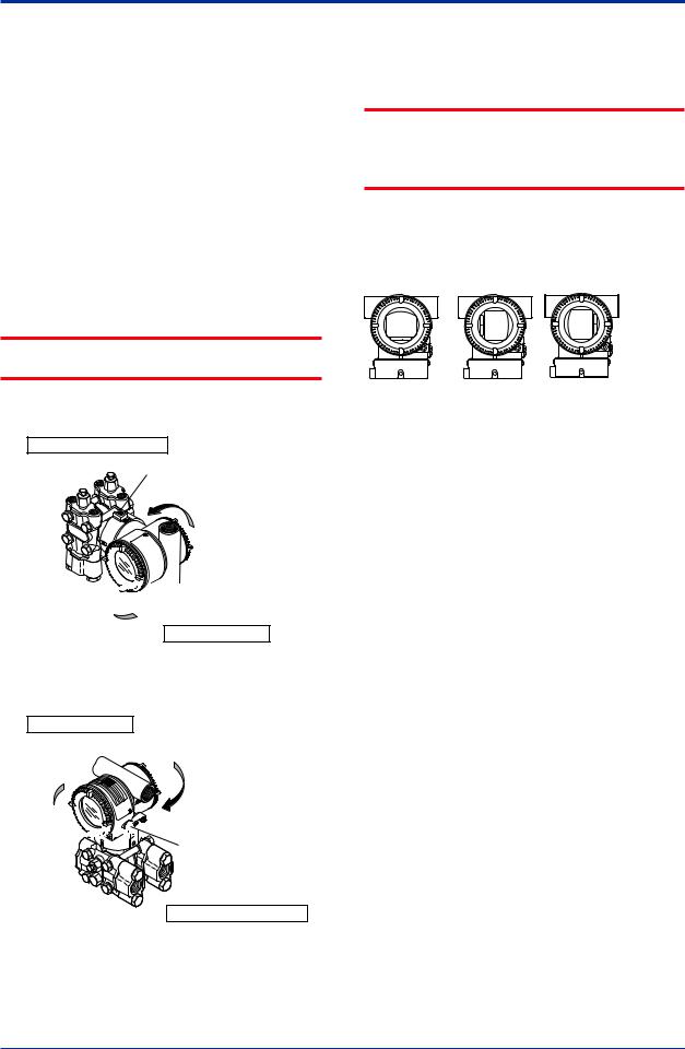
4.5Rotating Transmitter Section
The transmitter section can be rotated approximately 360° (180° to either direction or 360° to one direction from the original position at shipment, depending on the configuration of the instrument.) It can be fixed at any angle within above range.
1)Remove the two setscrews that fasten the transmitter section and capsule assembly, using theAllen wrench.
2)Rotate the transmitter section slowly and stop it at designated position.
3)Tighten the two setscrews to a torque of 1.5 N·m.
 IMPORTANT
Do not rotate the transmitter section more than the above limit.
Vertical impulse piping type
Pressure-detector section
Stopper
Rotate 0 to ±180° segments


 Conduit connection
Transmitter section
Horizontal impulse piping type
Transmitter section
Rotate 0 to ±180° segments


 Conduit connection
Zero-adjustment screw
Pressure-detector section
F0407.ai
Figure 4.7 Rotating Transmitter Section (Left Side
High Pressure Type)
4.6Changing the Direction of Integral Indicator
 IMPORTANT
Always turn OFF power, release pressure and remove a transmitter to non-hazardous area before disassembling and reassmbling an indicator.
An integral indicator can be installed in the following three directions. Follow the instructions in section 8.4 for removing and attaching the integral indicator.
F0408.ai
Figure 4.8 Integral Indicator Direction
IM 01C25B01-01E
 Loading…

User’s
Manual
Differential Pressure and
Pressure Transmitters
EJ110, EJ120,
EJ130, EJ310,
EJ430, and EJ440
IM 01C25B01-01E
IM 01C25B01-01E
13th Edition