- Manuals
- Brands
- Danfoss Manuals
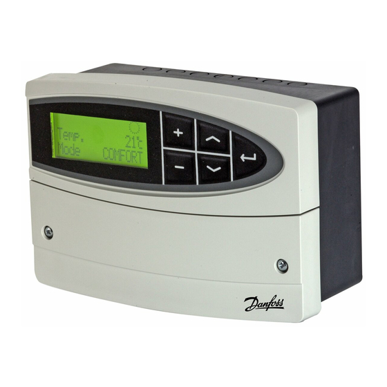
- Temperature Controller
- ECL Comfort 110
- Operating manual
-
Contents
-
Table of Contents
-
Bookmarks
Quick Links
Operating Guide
ECL Comfort 110, application 131
(valid as of software version 2.00)
English version
www.danfoss.com
Related Manuals for Danfoss ECL Comfort 110
Summary of Contents for Danfoss ECL Comfort 110
-
Page 1
Operating Guide ECL Comfort 110, application 131 (valid as of software version 2.00) English version www.danfoss.com… -
Page 2
The warning sign is used to emphasize special conditions that should be taken into consideration. This symbol indicates that this particular piece of information should be read with special attention. 2 | © Danfoss | 2016.05 VI.LV.A1.02… -
Page 3: Table Of Contents
Return T limit (return temp. limitation) 6000 Limit (return temperature limitation value) 6030 Gain — max. (return temp. limitation, maximum) 6035 Gain — min. (return temp. limitation, minimum) 6036 Intgr. time (Integration time) 6037 VI.LV.A1.02 © Danfoss | 2016.05 | 3…
-
Page 4
Electrical connections — 230 V a.c. — in general Connecting the temperature sensors and the ECL BUS External override How to identify your system type Adapting the ECL Comfort 110 controller Manual control Placing the temperature sensors Checklist, electrical connections… -
Page 5: Introduction
• Daily use (end user). Setting the desired flow temperature, mode and schedule • Maintenance (installer’s level). Setting of, for example, control functions. Access to Maintenance (installer’s level) on the ECL Comfort 110: Press and hold “Arrow-down” button for 3 sec.
-
Page 6: Settings Overview
Control param. – Xp 7184 80 K Control param. – Tn 7185 30 s Control param. – M1 run 7186 96 s Control param. – Nz 7187 Control param. – Min. on time 7189 6 | © Danfoss | 2016.05 VI.LV.A1.02…
-
Page 7
Application – Type 8600 Service – Code no. 9300 087B1670 Service – Ver. 9301 D200010516 Service – Backlight 9310 Service – Contrast 9311 Service – Language 9315 ENGLISH Service – MOD address 9320 VI.LV.A1.02 © Danfoss | 2016.05 | 7… -
Page 8: Daily Use
Actual room temperature Desired room temperature S2 des. T S3 act. T Actual flow temperature S3 des. T Desired flow temperature S4 act. T Actual return temperature S4 lim. T Desired return temperature limitation 8 | © Danfoss | 2016.05 VI.LV.A1.02…
-
Page 9: Select Control Mode
COMFORT< Wednesday Change the mode (AUTO, COMFORT, SAVING, or STANDBY). Set your personal schedule It is only possible to set the personal schedules if the ECL Comfort 110 controller has a built-in ECA 110 timer program. Wednesday < 04-01-12 8:32 This display will show the current day and time.
-
Page 10
The schedule has always two comfort periods a day. The start and stop times can be set in half-hourly intervals (30 min.). To arrange only one comfort period on a day: Set Start2 and Stop2 times to the same time value. 10 | © Danfoss | 2016.05 VI.LV.A1.02… -
Page 11: Maintenance
It is only necessary to set the correct date and time in connection with the first use of the ECL Comfort 110 controller or after a power break of more than 36 hours (see the chapter on Adapting the ECL Comfort 110 controller).
-
Page 12: Room T Limit (Room Temperature Limitation) 3000
This section is a general description for Room temperature limitation and is only relevant if you have installed a room temperature sensor (S2). The ECL Comfort 110 adjusts the desired flow temperature to compensate for the difference between the desired and the actual room temperature.
-
Page 13: Comfort T (Desired Room Temperature In Comfort Mode) 3180
The “Intgr. time” function can correct the desired flow temperature with max. 8 degrees. OFF: The control function is not influenced by the ‘Intgr. time’. Minor value: The desired room temperature is adapted quickly. Major value: The desired room temperature is adapted slowly. VI.LV.A1.02 © Danfoss | 2016.05 | 13…
-
Page 14
The actual room temperature is 2 degrees too high. The ‘Gain — max.’ is set to -3.5. The ‘Gain — min.’ is set to 2.0. Result: The desired flow temperature is changed by 2 x (-3.5) = -7.0 degrees. 14 | © Danfoss | 2016.05 VI.LV.A1.02… -
Page 15: Compensation 1 And 2 4000
The example shows that the desired flow temperature can be influenced when the compensation temperature gets below “Compensation temperature value 1”. Also, the desired flow temperature can be influenced when the compensation temperature gets above “Compensation temperature value 2”. VI.LV.A1.02 © Danfoss | 2016.05 | 15…
-
Page 16: Temp. (Compensation Temperature) 4060
Setting the compensation temperature value 1. When the temperature, measured by S1, falls below or gets higher than the set compensation value, the ECL Comfort 110 changes the desired flow temperature. The influence is set in ‘Gain — max.’ and ‘Gain — min.’.
-
Page 17: Compensation 2 5000
Setting the compensation temperature value 2. When the temperature, measured by S1, falls below or gets higher than the set compensation value, the ECL Comfort 110 changes the desired flow temperature. The influence is set in ‘Gain — max.’ and ‘Gain — min.’.
-
Page 18: Intgr. Time (Integration Time) 5065
‘Gain. min.’ (4063) is set to 2.5. The actual compensation temperature is 2°C (3 degrees below the limit value). Result: The desired flow temperature is changed by 2.5 x 3 = 7.5 degrees. 18 | © Danfoss | 2016.05 VI.LV.A1.02…
-
Page 19: Return T Limit (Return Temp. Limitation) 6000
This section is a general description for Return temperature limitation and is only relevant if you have installed a return temperature sensor (S4). The ECL Comfort 110 adjusts the desired flow temperature to compensate for the difference between the limitation temperature and the actual return temperature.
-
Page 20: Limit (Return Temperature Limitation Value) 6030
Minor value: The desired flow temperature is changed quickly. Major value: The desired flow temperature is changed slowly. If the ‘Gain’ is too high and / or the ‘Intgr. time’ too low, there is a risk of unstable control. 20 | © Danfoss | 2016.05 VI.LV.A1.02…
-
Page 21
The desired flow temperature is changed by 2.5 x 3 = 7.5 degrees. Temperature Temperature Time # 1 # Return temperature limit # 2 # Return temperature # 3 # Desired flow temperature # 4 # Action point VI.LV.A1.02 © Danfoss | 2016.05 | 21… -
Page 22: Control Param. (Control Parameters) 7000
5.0 mm x 15 sec. / mm = 75 sec. Rotating valves Running time = Turning degrees x actuator speed (sec. / degr.) Example: 90 degr. x 2 sec. / degr. = 180 sec. 22 | © Danfoss | 2016.05 VI.LV.A1.02…
-
Page 23: Nz (Neutral Zone) 7187
The setting should be kept as high as acceptable to increase the lifetime of the valve actuator. Setting examples Set value x 20 ms 40 ms (= 0.04 sec) 200 ms (= 0.2 sec) 1000 ms (= 1 sec) VI.LV.A1.02 © Danfoss | 2016.05 | 23…
-
Page 24
‘Tn’ = 0.85 x critical time period ‘Xp’ = 2.2 x proportional band value in the critical time period. If the regulation seems to be too slow, you can decrease the proportional band value by 10%. 24 | © Danfoss | 2016.05 VI.LV.A1.02… -
Page 25: Application 8000
Desired flow temperature # 1 # Standby temperature # 2 # Saving temperature # 3 # Desired saving temperature # 4 # Comfort temperature # 5 # Comfort period # 6 # Saving period VI.LV.A1.02 © Danfoss | 2016.05 | 25…
-
Page 26: P1 Exercise 8022
Exercises the control valve to avoid blocking in periods without cooling demand. The valve exercise is not active. The valve is opened daily for 15 minutes as from 12.00. The valve is closed as from 12.15. 26 | © Danfoss | 2016.05 VI.LV.A1.02…
-
Page 27: P1 Start T (Cooling Demand) 8078
Setting range OFF / Comfort / Saving By means of a switch or a relay contact the ECL Comfort 110 can be overridden to ‘Comfort’ or ‘Saving’ mode. The override switch or relay contact is connected to the input terminals 11 and 12. When closing the switch / relay contacts, the override is activated.
-
Page 28: Daylight (Daylight Saving Time Changeover) 8198
Setting range 0 . . . 15 This setting is relevant if more ECL Comfort 110 are connected in the same ECL Comfort system (connected via the ECL BUS). The ECL Comfort 110, which is physically connected with the S1 temperature sensor, must be the master of the entire system and must have the address 15.
-
Page 29: Type (Application Type) 8600
Press and hold for 5 sec. Hereafter the ECL Comfort 110 resets. An ECL Comfort 110, new from factory, will show “???” at start-up. Select application 131 by means of the + button. Press and hold the “arrow-down” button for 5 sec.
-
Page 30: Service 9000
Maintenance Service 9000 Code no. 9300 Information about the ECL Comfort 110’s code number. Example: 087B1670 Ver. (version no.) 9301 Info ABBBCCWWYY Information about the ECL Comfort 110’s version. = Hardware version BBB = Software version CC = Application version…
-
Page 31: Language 9315
Language 9315 Setting range ENGLISH / DANSK Choose the preferred language. MOD address (MODBUS address) 9320 Setting range 0 . . . 250 The MODBUS related functionality is used for production test only. VI.LV.A1.02 © Danfoss | 2016.05 | 31…
-
Page 32: Installation
93 x 139 mm. Insert the controller into the panel cut-out and fix it with the clamp which is placed horisontally on the controller. Establish the electrical connections. For further details on mounting, see the mounting guide. 32 | © Danfoss | 2016.05 VI.LV.A1.02…
-
Page 33: Electrical Connections — 230 V A.c. — In General
Not to be used Not to be used *: Ohmic load: 4 Amp.; Inductive load: 2 Amp. Wire cross section: 0.5 — 1.5 mm Incorrect connection can damage the TRIAC outputs (terminals 23, 24 and 25). VI.LV.A1.02 © Danfoss | 2016.05 | 33…
-
Page 34: Connecting The Temperature Sensors And The Ecl Bus
Cable lengths of more than 125 m may cause noise sensibility (EMC). External override ECL 110 11 12 # 1 # # 2 # Override by means of a relay (# 1 #) or a switch (# 2 #). 34 | © Danfoss | 2016.05 VI.LV.A1.02…
-
Page 35: How To Identify Your System Type
Installation How to identify your system type The ECL Comfort 110 is a universal controller that can be used for various systems. Based on the shown standard systems, it is possible to configure additional systems. Cooling system with heat exchanger…
-
Page 36: Adapting The Ecl Comfort 110 Controller
Installation Adapting the ECL Comfort 110 controller When you switch on the controller the first time, it will ask you to choose language (default language is English). Language English Choose your language. Options: English and Dansk (Danish). Accept and go to the next menu.
-
Page 37
Installation If the application 131 has already been chosen, the display shows: Application Type Go to the ‘Maintenance’ part for further setup of your controller. VI.LV.A1.02 © Danfoss | 2016.05 | 37… -
Page 38: Manual Control
Manual mode Pump P1 is OFF ( Pump Select control mode. Mode MANUAL< Wednesday Manual mode should only be used for maintenance purposes. In manual mode all control and safety functions are deactivated! 38 | © Danfoss | 2016.05 VI.LV.A1.02…
-
Page 39: Placing The Temperature Sensors
Place the sensor max. 15 cm from the mixing point. In systems with heat exchanger, Danfoss recommends that the ESMU-type to be inserted into the exchanger flow outlet. Make sure that the surface of the pipe is clean and even where the sensor is mounted.
-
Page 40: Checklist, Electrical Connections
Choose manual operation as controller mode. Check that valves open and close, and that required controlled units (pump etc.) start and stop when operated manually. Check that the temperatures shown in the display match the actual sensors. 40 | © Danfoss | 2016.05 VI.LV.A1.02…
-
Page 41: Frequently Asked Questions In Relation To Cooling Application
A PI control does the same as a P control, but the offset will disappear over time. A long ‘Intgr. time’ will give a slow but stable control, and a short ‘Intgr. time’ will result in a fast control but with a higher risk of oscillations. VI.LV.A1.02 © Danfoss | 2016.05 | 41…
-
Page 42: Definitions In Relation To Cooling Application
The circuit for cooling the room / building. Desired flow temperature Temperature set in the ECL Comfort 110 and influences from the room and / or return temperatures. This temperature is used as a reference for the control. Desired room temperature Temperature which is set as the desired room temperature.
-
Page 43
The time bars illustrate scheduled periods with comfort temperature. Disposal instruction: This product should be dismantled and its components sorted, if possible, in various groups before recycling or disposal. Always follow the local disposal regulations. VI.LV.A1.02 © Danfoss | 2016.05 | 43… -
Page 44: Vi.lv.a1.02
*087R9832* *VILVA102* 44 | © Danfoss | DHS-SRMT/DK | 2016.05 VI.LV.A1.02…
-
Contents
-
Table of Contents
-
Bookmarks
Quick Links
Instructions
ECL Comfort 110
Application 130
Weather compensated flow temperature
control of heating and boiler systems
User guide,
Installation & Maintenance
VI.KT.G2.02
DH-SMT/DK
© Danfoss 05/2007
Related Manuals for Danfoss ECL Comfort 110
Summary of Contents for Danfoss ECL Comfort 110
-
Page 1
Instructions ECL Comfort 110 Application 130 Weather compensated flow temperature control of heating and boiler systems User guide, Installation & Maintenance VI.KT.G2.02 DH-SMT/DK © Danfoss 05/2007… -
Page 2
The warning sign is used to emphasize special conditions that should be taken into consideration. This symbol indicates that this particular piece of information should be read with special attention. VI.KT.G2.02 VI.KT.G2.02 © Danfoss 05/2007 DH-SMT/DK DH-SMT/DK © Danfoss 05/2007… -
Page 3: Table Of Contents
Electrical connections — 24 V a.c. — in general Connecting the temperature sensors and the ECL BUS How to identify your system type Adapting the ECL Comfort 110 controller Manual control Placing the temperature sensors Connecting the room panel / remote control Checklist, electrical connections …………..45…
-
Page 4: Vi.kt.g2.02 © Danfoss
3183 Limit (return temp. limitation) 4030 18 50 °C Basic principles of application 130 for ECL Comfort 110 Gain — max. (return temp. limitation — max. influence) 4035 19 -2.0 Typically, the flow temperature is always adjusted according to your requirements.
-
Page 5: Vi.kt.g2.02 © Danfoss
Temperature overview 2 sec. Push the button to see the sensor (S1-S4) temperatures. It is only possible to set the personal schedules if the ECL Comfort 110 controller has a built-in ECA 110 timer program. Change between the temperature displays: ����������������…
-
Page 6
It is only necessary to set the correct date and time in connection with the first use of the change the start of this period. ECL Comfort 110 controller or after a power break of more than 36 hours (see the chapter Adapting the ECL Comfort 110 controller). -
Page 7
For quick setting, the graph can be used. The graph is intended for a T of 20 °C. If the room design data from example I is used, the slope will be approx. 1.7. VI.KT.G2.02 VI.KT.G2.02 © Danfoss 05/2007 DH-SMT/DK DH-SMT/DK © Danfoss 05/2007… -
Page 8
The ‘Gain — max.’ is set to -4.0. The ‘Gain — min.’ is set to 0.0. The ‘Slope’ is 1.8. Result: The desired flow temperature is changed by 2 x -4.0 x 1.8 = -14.4 degrees. VI.KT.G2.02 VI.KT.G2.02 © Danfoss 05/2007 DH-SMT/DK DH-SMT/DK © Danfoss 05/2007… -
Page 9
The ‘Gain — max.’ is set to -3.5. The ‘Gain — min.’ is set to 2.0. The ‘Slope’ is 1.8. Result: The desired flow temperature is changed by 2 x (-3.5) x 1.8 = -12.6 degrees. VI.KT.G2.02 VI.KT.G2.02 © Danfoss 05/2007 DH-SMT/DK DH-SMT/DK © Danfoss 05/2007… -
Page 10
The desired flow temperature is increased, when the return temperature gets below the set limit. Influence lower than 0: The desired flow temperature is decreased, when the return temperature gets below the set limit. VI.KT.G2.02 VI.KT.G2.02 © Danfoss 05/2007 DH-SMT/DK DH-SMT/DK © Danfoss 05/2007… -
Page 11
(line 5014). If a room temperature sensor or a room panel / remote control is connected, the boost stops when the room temperature is reached. VI.KT.G2.02 VI.KT.G2.02 © Danfoss 05/2007 DH-SMT/DK DH-SMT/DK © Danfoss 05/2007… -
Page 12
5014 Setting range Factory setting It is only possible make use of ‘Optimize’ if the ECL Comfort 110 controller has a built-in ECA OFF / 10 … 59 110 timer program or is connected to an ECA 61 / 63. -
Page 13
S1 T filter (outdoor temp. filter) 5081 Setting range Factory setting 1 … 200 Dampens the measured outdoor temperatures by the set factor. Fast (low filter constant) 200: Slow (high filter constant) VI.KT.G2.02 VI.KT.G2.02 © Danfoss 05/2007 DH-SMT/DK DH-SMT/DK © Danfoss 05/2007… -
Page 14
5 … 250 sec. 35 sec. ‘M1 run’ is the time it takes the controlled unit to move from fully closed to fully open position. Set the ‘M1 run’ according to the example. VI.KT.G2.02 VI.KT.G2.02 © Danfoss 05/2007 DH-SMT/DK DH-SMT/DK © Danfoss 05/2007… -
Page 15: Application
Factory setting GEAR / ABV GEAR Choose the actuator type for your valve. GEAR: Gear motor ABV: Thermo actuator (Danfoss type ABV) Control parameters (lines 6174-6187) are overruled if thermo actuator is chosen (ABV). VI.KT.G2.02 VI.KT.G2.02 © Danfoss 05/2007 DH-SMT/DK DH-SMT/DK…
-
Page 16: Dhw Prior. (Closed Valve / Normal Operation) 7052
SETBACK: The controller is in setback mode when terminals 11 and 12 are short- circuited. COMFORT: The controller is in comfort mode when terminals 11 and 12 are short- circuited. VI.KT.G2.02 VI.KT.G2.02 © Danfoss 05/2007 DH-SMT/DK DH-SMT/DK © Danfoss 05/2007…
-
Page 17: Knee Point 7162
Start the chosen application. Factory settings are restored. All personal settings will be deleted. It is recommended to make a note of your personal settings in the ‘Settings overview’ for future use. VI.KT.G2.02 VI.KT.G2.02 © Danfoss 05/2007 DH-SMT/DK DH-SMT/DK © Danfoss 05/2007…
-
Page 18: Service 8000
OFF: No backlight. Weak backlight. Strong backlight. Contrast (display contrast) 8311 Setting range Factory setting 0 … 20 The contrast of the display can be adjusted. High contrast Low contrast VI.KT.G2.02 VI.KT.G2.02 © Danfoss 05/2007 DH-SMT/DK DH-SMT/DK © Danfoss 05/2007…
-
Page 19: Installation
93 x 139 mm. Insert the controller into the panel cut-out and fix it with the clamp which Incorrect connection can damage the TRIAC outputs. is placed horisontally on the controller. Establish the electrical connections. For further details on mounting, see the mounting guide. VI.KT.G2.02 VI.KT.G2.02 © Danfoss 05/2007 DH-SMT/DK DH-SMT/DK © Danfoss 05/2007…
-
Page 20: Electrical Connections — 24 V A.c. — In General
Relay R2 4 (2) A Cable lengths of more than 125 m may cause noise sensibility (EMC). Wire cross section: 0.5 — 1.5 mm Incorrect connection can damage the TRIAC outputs. VI.KT.G2.02 VI.KT.G2.02 © Danfoss 05/2007 DH-SMT/DK DH-SMT/DK © Danfoss 05/2007…
-
Page 21: How To Identify Your System Type
How to identify your system type Adapting the ECL Comfort 110 controller When you switch on the controller the first time, it will ask you to choose language The ECL Comfort controller is a universal controller that can be used for various systems.
-
Page 22: Manual Control
Flow temperature sensor (ESMU, ESM-11 or ESMC) Place the sensor max. 15 cm from the mixing point. In systems with heat exchanger, 5 sec. Danfoss recommends that the ESMU-type to be inserted into the exchanger flow outlet. Go to manual mode. Actuator M1 is opening ( �����������…
-
Page 23: Connecting The Room Panel / Remote Control
The BUS is activated by setting the controller address to 15 (line 7199). etc.) start and stop when operated manually. Check that the temperatures shown in the display match the actual sensors. VI.KT.G2.02 VI.KT.G2.02 © Danfoss 05/2007 DH-SMT/DK DH-SMT/DK © Danfoss 05/2007…
-
Page 24: Frequently Asked Questions
Humidity, relative This value (stated in %) refers to the indoor moisture content compared to the max. moisture content. The relative humidity is measured by the ECA 62 / 63. VI.KT.G2.02 VI.KT.G2.02 © Danfoss 05/2007 DH-SMT/DK DH-SMT/DK © Danfoss 05/2007…
-
Page 25: Definitions
The definitions apply to the Comfort 110 series. Consequently, you might come across It must be collected separately with other electrical and electronic waste according to expressions that are not mentioned in your guide. local legislation. VI.KT.G2.02 VI.KT.G2.02 © Danfoss 05/2007 DH-SMT/DK DH-SMT/DK © Danfoss 05/2007…
-
Page 26
*VIKTG202* Danfoss can accept no responsibility for possible errors in catalogues, brochures and other printed material. Danfoss reserves the right to alter its products without notice. This also applies to products already on order provided that such alterations can be made without subsequential changes being necessary in specifications already agreed.
Архивная серия
Товары серии сняты с продажи
ECL Comfort 110 — это электронный одноконтурный регулятор, предназначенный для регулирования температуры подачи в системе теплоснабжения или регулирования постоянной температуры в системе ГВС.
Помимо регулирования температуры ECL 110 позволяет оптимизировать систему, ограничить температуру возвращаемого теплоносителя, а при помощи встроенного таймера значительно увеличить энергосбережение. Также имеются защитные функции, такие как защита от замерзания или защита от блокировки регулирующего клапана и насоса.
Регулятор имеет симисторные выходы для электроприводов регулирующих клапанов и релейные выходы для управления насосом, а также текстовый дисплей с подсветкой.
ECL Comfort 110 не требует отдельной клеммной панели, регулятор может быть смонтирован на DIN-рейке или на стене, а при помощи комплекта для монтажа его можно установить в вырез шкафа автоматизации.
Также нет нужды приобретать ключи управления для ECL Comfort 110, в регуляторе уже предустановлены приложения для управления системой отопления (приложение 130) и управления системой ГВС с емкостным или скоростным подогревателем (приложение 116).
Документация>>
Бренд:
Danfoss
Обсудить в Community

Товары серии
|
Название и артикул |
|---|
|
087B1249 Комплект для монтажа ECL 110 в вырезе шкафа |
||
|
|

Подпишитесь на наши новости
Первыми получайте уведомления о наших новостях в рассылке
перейти к содержанию
Руководство по установке приводов переменного тока и органов управления Danfoss ECL Comfort 110
Руководство по установке
ЭКЛ Комфорт 110


ЭКЛ Комфорт 110


Руководство по установке, ECL Comfort 110
230 В переменного тока

24 В переменного тока

ЕС-декларация соответствия
Перейти к:
https://store.danfoss.com/en/
Выберите: ECL Comfort 110 > Документы > Декларация ЕС:
https://assets.danfoss.com/approvals/188967/ID389638298581-0101.pdf or
Декларация Великобритании:
https://assets.danfoss.com/approvals/188970/ID389638299582-0101.pdf
?ECL Комфорт 110: www.heating.danfoss.com
?https://www.youtube.com/user/DanfossHeating -> Плейлисты -> Видео с практическими рекомендациями -> Видео по установке районного энергоснабжения
БАРНЫЙ КОД


Документы / Ресурсы
Рекомендации

✐
40 VI.KT.F4.50
© Danfoss 03/2013
DEN-SMT/DK
*087R9822*
*VIKTF450*
DEN-SMT/DK
VI.KT.F4.50
© Danfoss 03/2013
$2!&4
Инструкция
ECL Comfort 110
Применение 116
(действует применительно к версии
программного обеспечения 1.08)
Поддержание заданной температуры
горячей воды в системе горячего
водоснабжения (ГВС)
Инструкция пользователя
Установка и техническое обслуживание
перейти к содержанию
Руководство по установке приводов переменного тока и органов управления Danfoss ECL Comfort 110
Руководство по установке
ЭКЛ Комфорт 110
ЭКЛ Комфорт 110
Руководство по установке, ECL Comfort 110
230 В переменного тока
24 В переменного тока
ЕС-декларация соответствия
Перейти к:
https://store.danfoss.com/en/
Выберите: ECL Comfort 110 > Документы > Декларация ЕС:
https://assets.danfoss.com/approvals/188967/ID389638298581-0101.pdf or
Декларация Великобритании:
https://assets.danfoss.com/approvals/188970/ID389638299582-0101.pdf
?ECL Комфорт 110: www.heating.danfoss.com
?https://www.youtube.com/user/DanfossHeating -> Плейлисты -> Видео с практическими рекомендациями -> Видео по установке районного энергоснабжения
БАРНЫЙ КОД
Документы / Ресурсы
Рекомендации