-
Contents
-
Table of Contents
-
Troubleshooting
-
Bookmarks
Quick Links
UPS Network Management Card
Network-M2
User’s Guide
English
10/15/2020
2.0.5
Related Manuals for Eaton Network-M2
Summary of Contents for Eaton Network-M2
-
Page 1
UPS Network Management Card Network-M2 User’s Guide English 10/15/2020 2.0.5… -
Page 3
Google™ is a trademark of Google Inc. All other trademarks are properties of their respective companies. ©Copyright 2019 Eaton Corporation. All rights reserved. No part of this document may be reproduced in any way without the express written approval of Eaton Corporation. -
Page 4: Table Of Contents
1 Table of Contents TABLE OF CONTENTS ……………………….4 INSTALLING THE NETWORK MANAGEMENT MODULE …………….10 Unpacking the Network module……………………….10 Mounting the Network Module ……………………….10 Wiring the RS-485 Modbus RTU terminal ……………………..10 2.3.1 Modbus Common/GND (0V pin on terminal block) connection………………11 2.3.2 Cable shield connection (foiled or braised) ……………………
-
Page 5
3.4.2 Outlets — Group 1/ Group 2 ……………………….. 50 3.4.3 Access rights per profiles …………………………. 51 3.4.4 Troubleshooting…………………………..51 Protection ………………………………. 52 3.5.1 Agents list…………………………….52 3.5.2 Agent shutdown sequencing……………………….57 3.5.3 Scheduled shutdown…………………………60 3.5.4 Shutdown on power outage ……………………….61 Environment ……………………………. -
Page 6
4.1.1 Commissioning…………………………..159 4.1.2 Testing LDAP authentication ……………………….160 4.1.3 Limitations …………………………….160 Pairing agent to the Network Module ……………………..160 4.2.1 Pairing with credentials on the agent ……………………… 160 4.2.2 Pairing with automatic acceptance (recommended if done in a secure and trusted network)……..161 4.2.3 Pairing with manual acceptance … -
Page 7
5.2.3 References …………………………….. 200 Configuring user permissions through profiles……………………201 Decommissioning the Network Management module …………………. 201 SERVICING THE EMP ……………………….. 202 Description and features …………………………202 Unpacking the EMP…………………………..202 Installing the EMP …………………………..203 6.3.1 Defining EMPs address and termination ……………………203 6.3.2 Mounting the EMP …………………………. -
Page 8
7.7.2 Contextual help…………………………..242 7.7.3 get release info…………………………..243 7.7.4 history…………………………….. 244 7.7.5 ldap-test…………………………….244 7.7.6 logout……………………………… 246 7.7.7 maintenance …………………………… 246 7.7.8 modbus_message_display ……………………….246 7.7.9 modbus_statistics…………………………… 247 7.7.10 netconf …………………………….248 7.7.11 ping and ping6 …………………………..250 7.7.12 reboot …………………………….. -
Page 9
8.8.3 Action …………………………….. 265 SNMPv3 password management issue with Save and Restore ………………265 8.9.1 Affected FW versions…………………………265 8.9.2 Symptom …………………………….266 8.9.3 Cause……………………………… 266 8.9.4 Action …………………………….. 266 8.10 The alarm list has been cleared after an upgrade………………….. 266 8.10.1 Symptom ……………………………. -
Page 10: Installing The Network Management Module
Unpacking the Network module 2 Installing the Network Management Module 2.1 Unpacking the Network module The Network-M2 will include the following accessories: • QuickStart • USB AM to Micro USB/M/5P 5ft Cable Packing materials must be disposed of in compliance with all local regulations concerning waste.
-
Page 11: Modbus Common/Gnd (0V Pin On Terminal Block) Connection
Wiring the RS-485 Modbus RTU terminal If the Modbus Network Module is the last device installed in the network chain or the length of the network cable is excessive, termination needs to be enabled. For details on termination, see the Installing the Network Management Module>>>Wiring the RS-485 Modbus RTU terminal>>>Configuring the termination section.
-
Page 12: Configuring The Termination
Wiring the RS-485 Modbus RTU terminal Belden 9843-24AWG or equivalent cabling (3 twisted-pair shielded 120Ω cable with ground) is recommended. 2.3.5 Configuring the termination If the INDGW card is the last device installed in the network chain or the length of the network cable is excessive, termination needs to be enabled.
-
Page 13
Wiring the RS-485 Modbus RTU terminal Peel off the protection: Change the position of the termination switch according to your needs: Switch position No termination (default) Termination for two-wire networks One of the two position below can be used: Installing the Network Management Module – … -
Page 14: Accessing The Network Module
Accessing the Network Module Termination for four-wire networks 2.4 Accessing the Network Module 2.4.1 Accessing the web interface through Network 2.4.1.1 Connecting the network cable Security settings in the Network Module may be in their default states. For maximum security, configure through a USB connection before connecting the network cable. Connect a standard …
-
Page 15: Accessing The Web Interface Through Rndis
Accessing the Network Module If your device has an LCD, from the LCD’s menu, navigate to Identification>>>»COM card IPv4″. • Note the IP address of the card. • Go to the section: Accessing the web interface through Network. 2.4.2.1.2 With web browser through the configuration port For example, if your device does not have an LCD, the IP address can be discovered by accessing the web interface through RNDIS and browsing to Settings>Network.
-
Page 16
Accessing the Network Module 2.4.3.2 Web interface access through RNDIS 2.4.3.2.1 Configuring the RNDIS a Automatic configuration RNDIS driver is used to emulate a network connection from USB. After the card is connected to the PC, Windows® OS will automatically search for the RNDIS driver. On some computers, the OS can find the RNDIS driver then configuration is completed, and you can go to Accessing the web interface. -
Page 17
Accessing the Network Module STEP 4 – Then enter the configuration as below and validate (IP = 169.254.0.150 and mask = 255.255.0.0), click OK, then click on Close. Installing the Network Management Module – 17… -
Page 18: Accessing The Card Through Serial Terminal Emulation
2.4.3.2.2 Accessing the web interface STEP 1 – Be sure that the Device is powered on. STEP 2 – On the host computer, download the rndis.7z file from the website www.eaton.com/downloads and extract it. For more information, navigate to Servicing the Network Management Module>>>Accessing to the latest Network Module firmware/ driver section.
-
Page 19
After the card is connected to the PC, manual configuration of the driver is needed for Windows® OS to discover the serial connection. STEP 1 – On the host computer, download the rndis.7z file from the website www.eaton.com/downloads and extract it. STEP 2 – Plug the USB cable and go to Windows® Device Manager. -
Page 20: Modifying The Proxy Exception List
Accessing the Network Module STEP 7 – The installation is successful when the COM port number is displayed for the Gadget Serial device in the Windows® Device Manager. 2.4.4.3 Accessing the card through Serial It is intended mainly for automated configuration of the network and time settings of the network card. It can also be used for troubleshooting and remote reboot/reset of the network interface in case the web user interface is not accessible.
-
Page 21
Accessing the Network Module • Select the Connections tab • Press LAN Settings • Press ADVANCED • Add the address 169.254. * Installing the Network Management Module – 21… -
Page 22: Configuring Modbus
Configuring Modbus • Press OK. • Close Internet Explorer and re-open it. • Now you can access the address 169.254.0.1 with Internet Explorer and any other browser. 2.5 Configuring Modbus 2.5.1 Configuring the communication parameters • Access the web interface through Network or RNDIS •…
-
Page 23: Modbus Communication Monitoring Tool
Configuring Modbus • Type: Register/Discrete • Size in bytes • Number of modbus registers • Writable: True/False • Representation: Int16/Uint16/String/Boolean/… • Name • Description • Unit (Kelvin, A, V, W, VA, %, Hz, min, …) • Status to 0: status when the discrete equal 0 •…
-
Page 24
Configuring Modbus Installing the Network Management Module – 24… -
Page 25
Configuring Modbus Installing the Network Management Module – 25… -
Page 26
Configuring Modbus Installing the Network Management Module – 26… -
Page 27: Configuring The Network Module Settings
Configuring the Network Module settings 2.6 Configuring the Network Module settings Use the web interface to configure the Network Module. The main web interface menus are described below: 2.6.1 Menu structure Home: Overview and status of the Device (Active alarms, Outlet status, …). Installing the Network Management Module – 27…
-
Page 28
Configuring the Network Module settings Meters: Power quality meters and logs. Controls: Device and outlets control. Protection: Agents list, Agents shutdown sequencing, Shutdown on power outage. Environment: Commissioning/Status, Alarm configuration, Information. Settings: Network Module settings. Maintenance: Firmware, Services, Resources, System logs. Legal: Legal information, Availability of source code, Notice for proprietary elements. Profile: Displays user profile, password change, account information and logout. -
Page 29: Contextual Help Of The Web Interface
Login page 3 Contextual help of the web interface 3.1 Login page The page language is set to English by default but can be switched to browser language when it is managed. After navigating to the assigned IP address, accept the untrusted certificate on the browser. 3.1.1 Logging in for the first time 3.1.1.1 1. Enter default password As you are logging into the Network Module for the first time you must enter the factory set default username and password.
-
Page 30: Troubleshooting
Home 3.1.2 Troubleshooting How do I log in if I forgot my password? Action • Ask your administrator for password initialization. • If you are the main administrator, your password can be reset manually by following steps described in the Servicing the Network Management Module>>>Recovering main administrator password Web user interface is not up to date after a FW upgrade Symptom After an upgrade:…
-
Page 31: Information/Status On The Top Bar
Home 3.2.1 Information/Status on the top bar • Card name: Displays the card name. • Device name: Displays by default the device model or the system name if filled in the section Contextual help>>>Maintenance>>>System information. • Date and time: Displays local time but not the UTC time. •…
-
Page 32
Home Controls: Device and outlets control. Protection: Agents list, Agents shutdown sequencing, Shutdown on power outage. Environment: Commissioning/Status, Alarm configuration, Information. Settings: Network Module settings. Maintenance: Firmware, Services, Resources, System logs. Legal: Legal information, Availability of source code, Notice for proprietary elements. Profile: Displays user profile, password change, account information and logout. Help: Opens full documentation in a separate browser page. -
Page 33: Energy Flow Diagram
Home 3.2.3 Energy flow diagram 3.2.3.1 Line interactive UPS 3.2.3.2 Online UPS 3.2.3.3 ATS Contextual help of the web interface – 33…
-
Page 34
Home 3.2.3.4 Diagram elements description Description and Description Possible states below the symbol symbols Good Warning Fault Input Main utility input. In range Out of nominal range Output Output of the UPS. Protected In overload In short circuit Powered Not protected AVR device The equipment is protected and… -
Page 35
Home Maintenance bypass Maintenance bypass closed. Maintenance (optional) ATS device The equipment is powered through an ATS device. Description and Description Possible states symbols Green Orange Black Wiring Electrical connection between Energy flow In overload No energy blocks. Out of nominal range Unknown 3.2.3.5 Details … -
Page 36: Outlet Status
Home Input measures Output measures Voltage (V) Voltage (V) Current (A) Current (A) Frequency (Hz) Frequency (Hz) 3.2.3.6.2 Example #2 Dual input sources with 3 phases in and 3 phases out Input measures (main and secondary) Output measures Phase #1 Phase #2 Phase #3 Phase #1…
-
Page 37: Energy Flow Diagram Examples
Home 3.2.7 Energy flow diagram examples 3.2.7.1 Line interactive UPS 3.2.7.1.1 Normal mode 3.2.7.1.2 Buck/Boost mode Contextual help of the web interface – 37…
-
Page 38
Home 3.2.7.1.3 Battery mode 3.2.7.1.4 Off mode Contextual help of the web interface – 38… -
Page 39
Home 3.2.7.2 Online UPS with single input source 3.2.7.2.1 Online mode 3.2.7.2.2 Bypass mode Contextual help of the web interface – 39… -
Page 40
Home 3.2.7.2.3 Battery mode 3.2.7.2.4 Off mode Contextual help of the web interface – 40… -
Page 41
Home 3.2.7.2.5 HE mode / ESS mode 3.2.7.3 Online UPS with dual inputs sources and Maintenance bypass 3.2.7.3.1 Online mode Contextual help of the web interface – 41… -
Page 42
Home 3.2.7.3.2 Bypass mode 3.2.7.3.3 Battery mode Contextual help of the web interface – 42… -
Page 43
Home 3.2.7.3.4 HE mode / ESS mode 3.2.7.3.5 Maintenance bypass mode Contextual help of the web interface – 43… -
Page 44: Access Rights Per Profiles
Home 3.2.7.4 ATS 3.2.7.4.1 Normal mode 3.2.7.4.2 Prefered source missing 3.2.8 Access rights per profiles Administrator Operator Viewer Home 3.2.8.1 For other access rights For other access rights, see the Information>>>Access rights per profiles section. Contextual help of the web interface – 44…
-
Page 45: Meters
Meters 3.3 Meters Gauge color code: • Green: Value inside thresholds. • Orange/Red: Value outside thresholds. • Grey: No thresholds provided by the device. 3.3.1 Main utility input Displays the product main utility measures. • Current (A) • Voltage (V) 3.3.2 Second utility input (if available) Contextual help of the web interface – …
-
Page 46: Output
Meters If presents, displays the product second utility measures. • Current (A) • Voltage (V) 3.3.3 Output • Voltage (V) • Power (W) • Current (A) 3.3.4 Battery status Battery status section is an overview of the battery information. The information displayed depends on the device. Contextual help of the web interface – …
-
Page 47: Battery Health
Meters 3.3.4.1 Overview/Environment • Type • Nominal capacity • Nominal voltage • Capacity remaining • Runtime • State • Recommended replacement date • State of health • Voltage • Current • Temperature • Min cell voltage • Max cell voltage •…
-
Page 48: Logs
Meters • None • Scheduled • In progress • Aborted • Done 3.3.6 Logs This log configuration allows to define the log acquisition frequency of the Device measures only. The sensors measures logs acquisition is not settable and done every minutes. Sensors measures logs are accessible in Environment menu.
-
Page 49: Access Rights Per Profiles
Controls 3.3.7.1 For other settings For other settings, see the Information>>>Default settings parameters section. 3.3.8 Access rights per profiles Administrator Operator Viewer Meters Battery health: Launch test/Abort Logs configuration 3.3.8.1 For other access rights For other access rights, see the Information>>>Access rights per profiles …
-
Page 50: Outlets — Group 1/ Group 2
Controls • Safe OFF This will shut off the load. Protected applications will be safely powered down. This control is available only if the status is not OFF and if there are no active commands running. • Safe reboot This will shut off and then switch ON the load.
-
Page 51: Access Rights Per Profiles
Controls This control is available only if the status is not OFF and if there are no active commands running. • Switch ON This will switch ON the load connected to the associated load segment. This control is available when status is OFF and if there are no active commands running. 3.4.2.3 Pending action Displays the delay before shutdown and delay before startup.
-
Page 52: Protection
After automatic acceptance, make sure that all listed agents belong to your infrastructure. If not, access may be revoked using the Delete button. For maximum security, Eaton recommend following one of the two methods on the certificate settings page: • Import client certificates manually.
-
Page 53
Protection 3.5.1.2 Agents list table The table displays the IPP agent list that is connected to the Network Module and includes the following details: • Name • Address • Version of the Agent • Power source (Policy) • Delay (in seconds) • OS shutdown duration (in seconds) •… -
Page 54
Protection 3.5.1.5 Troubleshooting Card wrong timestamp leads to «Full acquisition has failed» error message on Software Symptoms: IPP/IPM shows the error message «The full data acquisition has failed» even if the credentials are correct. Possible cause: The Network module timestamp is not correct. Probably the MQTT certificate is not valid at Network module date. -
Page 55
Protection Software is not able to communicate with the Network module Symptoms • In the Network Module, in Contextual help>>>Protection>>>Agent list>>>Agent list table , agent is showing «Lost» as a status. • In the Network Module, in Contextual help>>>Settings>>>Certificate>>>Trusted remote certificates , the status of the Protected applications (MQTT) is showing «Not valid yet». -
Page 56
*.0 that (are) located folder Eaton\IntelligentPowerProtector\configs\tls. Client server is not restarting Symptom Utility power has been restored, the UPS and its load segments are powered on, but the Client server does not restart. Possible Cause The “Automatic Power ON” server setup setting might be disabled. -
Page 57: Agent Shutdown Sequencing
Protection 3.5.2 Agent shutdown sequencing 3.5.2.1 Agent shutdown sequence timing All agents that are connected to the Network Module are displayed in tables by power sources. • Primary • Group 1 • Group 2 The ‘local agent’ setting is used for setting for example a minimum shutdown duration, or a power down delay for a load segment that has no registered shutdown agents.
-
Page 58
Protection • Name • Delay (in seconds) • OS shutdown duration (in seconds) 3.5.2.2 Actions 3.5.2.2.1 Set Delay Select and directly change the setting in the table and then Save. 3.5.2.2.2 Set OS shutdown duration Select and directly change the setting in the table and then Save. 3.5.2.3 Examples Examples below show the impact of agent settings on the shutdown sequence for a shutdown or an immediate shutdown. -
Page 59
Protection 3.5.2.3.2 Example #2 → Shutdown time: 180s → Immediate shutdown time: 180s Contextual help of the web interface – 59… -
Page 60: Scheduled Shutdown
Protection The trigger in the diagram is the moment when the shutdown sequence starts, and it is defined in the Contextual help>>>Protection>>>Scheduled shutdown or the Contextual help>>>Protection>>>Shutdown on power outage sections for each power source. 3.5.2.4 Access rights per profiles Administrator Operator Viewer Protection/Agent settings 3.5.2.4.1 For other access rights For other access rights, see the Information>>>Access rights per…
-
Page 61: Shutdown On Power Outage
Protection 3.5.3.2.2 Delete Select a schedule shutdown and press the Delete button to delete the scheduled shutdown. 3.5.3.2.3 Edit Press the pen icon to edit schedule shutdown and to access the settings: 3.5.3.3 Access rights per profiles Administrator Operator Viewer Protection/Scheduled shutdowns 3.5.3.3.1 For other access rights For other access rights, see the…
-
Page 62
Protection in the correct order. For example, applications first, database servers next, and storage last. It is also possible to turn off some outlets to reduce power consumption and get longer battery runtime for the most important devices. For examples on Powering down applications see the Servicing the Network Management Module>>>Powering down/up applications examples section. -
Page 63
Protection • To initiate the sequence when the battery reaches the set capacity in (%) • To initiate or end the shutdown sequence after the set time in (s) before the end of backup time. When there are several conditions to start the shutdown sequence, the shutdown sequence will start as soon as one of the condition is reached. -
Page 64
Protection Example 2: Immediate OFF Example 4: Custom Contextual help of the web interface – 64… -
Page 65
Protection Settings #1 Contextual help of the web interface – 65… -
Page 66
Protection Settings #2 3.5.4.1.2 On low battery warning In some cases, like a renewed power failure or failed battery, the capacity is much lower than anticipated. The UPS gives a Low battery warning when there is 2 — 3 minutes of estimated runtime left, depending on the UPS and its settings. This time is typically enough for shutting down a server but does not allow sophisticated sequential shutdown schemes. -
Page 67
Protection 3.5.4.1.3 When utility comes back These settings define the restart sequence when utility comes back. For example, this allows sequential startup of the IT system so that network and storage devices are connected to ‘Primary’ and start up immediately. After a delay database servers in Group1 are powered up, and then application and web servers in Group 2 are powered up. -
Page 68: Environment
Environment 3.5.4.3 Troubleshooting Action not allowed in Control/Schedule/Power outage policy Symptom Below message is displayed when you access the Control, Schedule or Power outage policy page. This action is not allowed by the UPS. To enable it, please refer to the user manual of the UPS and its instructions on how to configure the UPS settings and allow remote commands.
-
Page 69
Environment • Name • Location – location-position-elevation • Temperature • Humidity • Dry contact #1 – Status and name • Dry contact #2 – Status and name • Communication – Connected/Lost with dates 3.6.1.2 Actions 3.6.1.2.1 Download sensors measures Press the Download sensors measures button to download the sensors log file: If available, possible measures are listed below: •… -
Page 70
Environment 1. Select the sensors. 2. Press the Define offset button to adjust the temperature and humidity offsets of the selected sensors. 3. Extend the temperature or humidity section. 4. Set the offsets in the cell, temperatures and humidity will be updated accordingly. 5. -
Page 71
Environment The dry contact is close and this is normal because it is configured as normally close. The dry contact is open and this is normal because it is configured as normally open. The dry contact is open and this is not normal because it is configured as normally close. The dry contact is close and this is not normal because it is configured as normally open. -
Page 72
Environment 3.6.1.5 Troubleshooting EMP detection fails at discovery stage In the Network Module, in Contextual help>>>Environment>>>Commissioning/Status , EMPs are missing in the Sensor commissioning table. Symptom #1 The EMPs green RJ45 LED (FROM DEVICE) is not ON. Possible causes The EMPs are not powered by the Network module. Action #1-1 Launch again the discovery, if it is still not ok, go to Action #1-2. -
Page 73: Alarm Configuration
Environment 2- Launch the discovery. 3.6.1.5.1 For other issues For details on other issues, see the Troubleshooting section. 3.6.2 Alarm configuration Humidity, temperatures or dry contacts deactivated during commissioning are not displayed. Gauge color code: • Green: Value inside thresholds. • Orange/Red: Value outside thresholds.
-
Page 74
Environment c Set Hysteresis Enable the alarm first and change the setting in the table and then Save. The hysteresis is the difference between the value where the alarm turns ON from turning OFF and the value where it turns OFF from turning ON. -
Page 75
Environment 3.6.2.3 Dry contacts The table shows the following settings for each dry contact: • Name • Location • Enabled – yes/no • Alarm severity – Info/Warning/Critical 3.6.2.3.1 Actions a Set Enabled Enable the alarm first and then change the setting in the table and then Save. When disabled, no alarm will be sent. -
Page 76: Information
Environment Temperature Enabled — No Enabled — No/Yes Low critical – 0°C/32°F low critical<low warning<high warning<high critical Low warning – 10°C/50°F High warning – 70°C/158°F High critical – 80°C/176°F Humidity Enabled — No Enabled — No/Yes Low critical – 10% 0%<low critical<low warning<high warning<high critical<100% Low warning – 20% High warning –…
-
Page 77
Environment • Physical name • Vendor • Part number • Firmware version • UUID • Serial number • Location 3.6.3.1 Access rights per profiles Administrator Operator Viewer Environment/Information 3.6.3.1.1 For other access rights For other access rights, see the Information>>>Access rights per profiles … -
Page 78: Settings
Settings 3.7 Settings 3.7.1 General 3.7.1.1 System details 3.7.1.1.1 Location Text field that is used to provide the card location information. Card system information is updated to show the defined location. 3.7.1.1.2 Contact Text field that is used to provide the contact name information. Card system information is updated to show the contact name.
-
Page 79
Settings 2. Select the time zone for your geographic area from the time zone pull-down menu or with the map. 3. Save the changes. DST is managed based on the time zone. 3.7.1.2 Email notification settings For examples on email sending configuration see the Servicing the Network Management Module>>>Subscribing to a set of alarms for email notification section. -
Page 80
Settings c Edit Press the pen icon to edit email sending configuration: You will get access to the following settings: • Custom name • Email address • Status – Active/Inactive • Hide the IP address from the email body – Disabled/Enabled This setting will be forced to Enabled if Enabled in the SMTP settings. •… -
Page 81
Settings 3.7.1.3 SMTP settings SMTP is an internet standard for electronic email transmission. The following SMTP settings are configurable: Contextual help of the web interface – 81… -
Page 82
Settings • Server IP/Hostname – Enter the host name or IP address of the SMTP server used to transfer email messages in the SMTP Server field. • Port • Default sender address • Hide the IP address from the email body – Disabled/Enabled If Enabled, it will force this setting to Enabled in the Email notification settings. -
Page 83
Settings Email notification settings No email 5 configurations maximum Custom name — 128 characters maximum Email address — 128 characters maximum Hide IP address from the email body — enable/disabled Status — Active/Inactive • Alarm notifications Active — No/Yes All card events – Subscribe/Attach logs Critical alarm –… -
Page 84
Settings 3.7.1.5 Access rights per profiles Administrator Operator Viewer General 3.7.1.5.1 For other access rights For other access rights, see the Information>>>Access rights per profiles section. 3.7.1.6 CLI commands email-test Description mail-test sends test email to troubleshoot SMTP issues. Help Usage: email-test <command>… -
Page 85
Settings time Description Command used to display or change time and date. Help For Viewer and Operator profiles: time -h Usage: time [OPTION]… Display time and date. -h, —help display help page -p, —print display date and time in YYYYMMDDhhmmss format For Administrator profile: time -h Usage: time [OPTION]… -
Page 86: Local Users
Settings 3.7.2 Local users 3.7.2.1 Local users table The table shows all the supported local user accounts and includes the following details: • Username • Email • Profile • Status – Status could take following values – Inactive/Locked/Password expired/Active For the list of access rights per profile refer to the section Full documentation>>>Information>>>Access rights per profiles.
-
Page 87
Settings d Global settings Press Save after modifications. Password settings To set the password strength rules, apply the following restrictions: • Minimum length • Minimum upper case • Minimum lower case • Minimum digit • Special character Password expiration To set the password expiration rules, apply the following restrictions: •… -
Page 88
Settings • Main administrator password never expire Main administrator password never expires If this feature is disabled, the administrator account can be locked after the password expiration. If Enabled, the administrator password never expires, make sure it is changed regularly. Lock account •… -
Page 89
Settings Local users 1 user only: 10 users maximum: • Active — Yes • Active — Yes/No • Profile — Administrator • Profile — Administrator/Operator/Viewer • Username — admin • Username — 255 characters maximum • Full Name — blank • Full Name — 128 characters maximum • Email — blank • Email — 128 characters maximum • Phone — blank • Phone — 64 characters maximum •… -
Page 90: Remote Users
Settings 3.7.2.4.1 For other CLI commands See the CLI commands in the Information>>>CLI section. 3.7.2.5 Troubleshooting How do I log in if I forgot my password? Action • Ask your administrator for password initialization. • If you are the main administrator, your password can be reset manually by following steps described in the Servicing the Network Management Module>>>Recovering main administrator password 3.7.2.5.1 For other issues…
-
Page 91
Settings 3.7.3.1.1 Actions a Configure 1. Press Configure to access the following LDAP settings: • Active • Base access Contextual help of the web interface – 91… -
Page 92
Settings • Security SSL – None/Start TLS/SSL Verify server certificate • Primary server – Name/Hostname/Port • Secondary server – Name/Hostname/Port • Credentials – Anonymous search bind/Search user DN/Password • Search base – Search base DN • Request parameters • User base DN • User name attribute •… -
Page 93
Settings 1. Press Users preferences to define preferences that will apply to all LDAP users • Language • Temperature • Date format • Time format 2. Click Save. 3.7.3.2 RADIUS Radius is not a secured protocol, for a maximum security, it is recomended to use LDAP over TLS. The table shows all the supported severs and includes the following details: Contextual help of the web interface – … -
Page 94
Settings • Name — descriptive name for the RADIUS server • Address — hostname or IP address for the RADIUS server • Status — whether the RADIUS server is active or inactive 3.7.3.2.1 Actions a Configure 1. Press Configure to access the following RADIUS settings: •… -
Page 95
Settings b Profile mapping For the list of access rights per profile refer to the section Full documentation>>>Information>>>Access rights per profiles. 1. Press Profile mapping to map RADIUS profile to local profiles. 2. Click Save. c Users preferences All users preferences will apply to all remote users (LDAP, RADIUS). 1. -
Page 96
Settings • Temperature • Date format • Time format 2. Click Save. 3.7.3.3 Default settings and possible parameters — Remote users Default setting Possible parameters LDAP Configure Configure • Active – No • Active – No/yes • Security • Security SSL –… -
Page 97
Settings RADIUS Configure Configure • Active – No • Active – Yes/No • Retry number – 0 • Retry number – 0 to 128 • Primary server • Primary server Name – blank Name – 128 characters maximum Secret – blank Address –… -
Page 98
Settings 3.7.3.5 CLI commands ldap-test Description Ldap-test help to troubleshoot LDAP configuration issues or working issues. Help Usage: ldap-test <command> [OPTION]… Test LDAP configuration. Commands: ldap-test -h, —help, Display help page ldap-test —checkusername <username> [—primary|—secondary] [-v] Check if the user can be retrieve from the LDAP server <username>… -
Page 99
Settings logout Description Logout the current user. Help logout <cr> logout the user whoami Description whoami displays current user information: • Username • Profile • Realm 3.7.3.5.1 For other CLI commands See the CLI commands in the Information>>>CLI section. 3.7.3.6 Troubleshooting How do I log in if I forgot my password? Action •… -
Page 100: Network & Protocol
Settings 3.7.4 Network & Protocol 3.7.4.1 Network 3.7.4.1.1 IPv4 Any modifications are applied after the Network Module reboots. Press the Edit button to configure the network settings, select either the Manual or DHCP settings option: Contextual help of the web interface – 100…
-
Page 101
Settings a Manual Select Manual, and then enter the network settings if the network is not configured with a BootP or DHCP server. • Enter the IP Address. The Network Module must have a unique IP address for use on a TCP/IP network. •… -
Page 102
Settings a Current configuration • Address • Gateway b Address settings • Enabled • Mode (Manual/DHCP) • Address • Prefix • Gateway Contextual help of the web interface – 102… -
Page 103
Settings 3.7.4.1.3 DNS/DHCP The DNS is a hierarchical decentralized naming system for computers, services, or other resources connected to the Internet or a private network. Press the Edit button to configure the network settings, select either the Static or Dynamic settings. a Manual •… -
Page 104
Settings • Secondary DNS server. Enter the IP address of the secondary DNS server that provides the translation of the domain name to the IP address when the primary DNS server is not available. b DHCP • Enter the Network Module Hostname. 3.7.4.1.4 Ethernet A LAN is a computer network that interconnects computers within a limited area. … -
Page 105
Settings 3.7.4.2.1 HTTPS Only https is available. The default network port for https is 443. For additional security, the ports can be changed on this page. Press Save after modifications. Since only https is available, port 80 is not supported. 3.7.4.2.2 Syslog a Settings This screen allows an administrator to configure up to two syslog servers. -
Page 106
Settings Press Save after modifications. 2- Configure the syslog server: • Click the edit icon to access settings. • Enter or change the server name. • Select Yes in the Active drop-down list to activate the server. • Enter the Hostname and Port. • Select the Protocol – UDP/TCP. •… -
Page 107
Settings HTTPS Port — 443 Port — x-xxx Syslog Inactive Inactive/Active • Server#1 • Server#1 Name – Primary Name – 128 characters maximum Status – Disabled Status – Disabled/Enabled Hostname – empty Hostname – 128 characters maximum Port – 514 Port –… -
Page 108
Settings 3.7.4.5 CLI commands netconf Description Tools to display or change the network configuration of the card. Help For Viewer and Operator profiles: netconf -h Usage: netconf [OPTION]… Display network information and change configuration. -h, —help display help page -l, —lan display Link status and MAC address -4, —ipv4… -
Page 109
Settings netconf -h Usage: netconf [OPTION]… Display network information and change configuration. -h, —help display help page -l, —lan display Link status and MAC address -d, —domain display Domain mode, FQDN, Primary and Secondary DNS -4, —ipv4 display IPv4 Mode, Address, Netmask and Gateway -6, —ipv6 display IPv6 Mode, Addresses and Gateway Set commands are used to modify the settings. -s, —set-lan <link speed> Link speed values: auto Auto negotiation 10hf 10 Mbps — Half duplex 10ff 10 Mbps — Full duplex 100hf 100 Mbps — Half duplex 100ff 100 Mbps — Full duplex 1000ff 1.0 Gbps — Full duplex -f, —set-domain hostname <hostname> set custom hostname -f, —set-domain <mode> Mode values: — set custom Network address, Netmask and Gateway: manual <domain name> <primary DNS> <secondary DNS> — automatically set Domain name, Primary and Secondary DNS dhcp -i, —set-ipv4 <mode> Mode values: — set custom Network address, Netmask and Gateway manual <network> <mask> <gateway> — automatically set Network address, Netmask and Gateway dhcp -x, —set-ipv6 <status> Status values: — enable IPv6 enable — disable IPv6 disable… -
Page 110
Settings -> Display Link status and MAC address netconf -l -> Set Auto negotiation to Link netconf -s auto -> Set custom hostname netconf -f hostname ups-00-00-00-00-00-00 -> Set Adress, Netmask and Gateway netconf -i manual 192.168.0.1 255.255.255.0 192.168.0.2 ->… -
Page 111: Snmp
Settings traceroute and traceroute6 Description Traceroute and traceroute6 utilities are for checking the configuration of the network. Help traceroute Specify maximum number of hops <Hostname or IP> Remote system to trace traceroute6 Specify maximum number of hops <IPv6 address> IPv6 address 3.7.4.5.1 For other CLI commands See the CLI commands in the Information>>>CLI …
-
Page 112
Settings SNMP monitoring Battery status, power status, events, and traps are monitored using third-party SNMP managers. To query SNMP data, you do not need to add SNMP Managers to the Notified Application page. To set-up SNMP managers: • Configure the IP address. •… -
Page 113
Settings b Configure the SNMP V1 settings: 1. Click the edit icon on either Read Only or Read/Write account to access settings: 2. Enter the SNMP Community Read-Only string. The Network Module and the clients must share the same community name to communicate. -
Page 114
Settings c Configure the SNMP V3 settings: 1. Click the edit icon on either Read Only or Read/Write account to access settings: 2. Edit the user name. 3. Select Active in the Enabled drop-down list to activate the account. 4. Select access level. •… -
Page 115
Settings 6. If Auth is selected on the communication security mechanism, select the Authentication algorithms. It is recommended to set SHA256/SHA384/SHA512 with the AES192/AES256 Privacy algorithms. • SHA— SHA1 is not recommended as it is not secured. • SHA256—fill in password and privacy keys. The password can be between 8 and 24 characters and use a combination of alphanumeric and the following special characters <>&@#%_=:;,./?|$*. -
Page 116
Settings 3.7.5.2.1 Actions a Add 1. Press the New button to create new trap receivers. 2. Set following settings: • Enabled – Yes/No • Application name • Hostname or IP address • Port • Protocol – V1/V3 • Trap community (V1) / User (V3) 3. -
Page 117
Settings 3.7.5.3 Link to SNMP traps • UPS Mib • ATS Mib • Sensor Mib 3.7.5.4 Default settings and possible parameters — SNMP Default setting Possible parameters SNMP Activate SNMP — disabled Activate SNMP — disable/enable Port — 161 Port — x-xxx SNMP V1 —… -
Page 118: Modbus
Settings 3.7.5.4.1 For other settings For other settings, see the Information>>>Default settings parameters section. 3.7.5.5 Access rights per profiles Administrator Operator Viewer SNMP 3.7.5.5.1 For other access rights For other access rights, see the Information>>>Access rights per profiles section. 3.7.5.6 Troubleshooting SNMPv3 password management issue with Save and Restore Affected FW versions…
-
Page 119
Settings This section is only for the Modbus Network ModuleINDGW For instructions on connecting Modbus RTU see the section Installing the Network Management Module>>>Wiring the RS-485 Modbus RTU terminal>>>Configuring the termination. For instructions on configuring Modbus see the section Installing the Network Management Module>>>Configuring Modbus 3.7.6.1 Modbus RTU The following Modbus RTU settings are configurable: •… -
Page 120
Settings 3.7.6.3 Mapping configuration 3.7.6.3.1 Mapping configuration table The table shows all the mapping configuration and includes the following details: • Name • • Transport • Access • Illegal read behaviour • Coil/register base address shift 3.7.6.3.2 Actions a Add Press the New button to create new mapping configuration. -
Page 121
Port — 502 Port — x-xxx Mapping configuration No mapping Name – 128 characters maximum Map – Eaton ModbusMS compatible Transport – RTU/TCP Device ID – from 1 to 247 Access – None/Read only/Read/Write Illegal read behaviour – Return exception/Return zeros Coil/register base address shift –… -
Page 122
Settings 3.7.6.4.1 For other settings For other settings, see the Information>>>Default settings parameters section. 3.7.6.5 Access rights per profiles Administrator Operator Viewer Modbus* *for INDGW only 3.7.6.5.1 For other access rights For other access rights, see the Information>>>Access rights per profiles … -
Page 123
Settings modbus_statistics This section is only for the Modbus Network Module INDGW Description modbus_statistics displays Modbus RTU and TCP status and server statistics: • Bus character overrun count • Bus frame error count • Bus parity error count • Buffer overrun count •… -
Page 124: Certificate
Settings 3.7.6.7 Troubleshooting Modbus communication doesn’t work Symptoms • Communication doesn’t work Refer to the section Servicing the Network Management Module>>>Configuring Modbus to get configuration and testings information. Possible cause • Incorrect communication parameters. Verify that the communication parameters are set to the desired settings. 3.7.6.7.1 For other issues For details on other issues, see the Troubleshooting …
-
Page 125
Settings After automatic acceptance, make sure that all listed clients belong to your infrastructure. If not, access may be revoked using the Delete button. The use of this automatic acceptance should be restricted to a secured and trusted network. For maximum security, we recommend following one of the two methods on the certificate settings page: •… -
Page 126
Settings A confirmation window appears, press Continue to proceed, this operation cannot be recovered. Revoke will replace current certificate by a new self-signed certificate. This may disconnect connected applications: — Web browsers — Shutdown application — Monitoring application The certificate that is taken out of use with the revoke action cannot be recovered. b Export Exports the selected certificate on your OS browser window. -
Page 127
Settings • Actions Generate a new self-signed certificate. Generate CSR. Import certificate (only available when CSR is generated). • Details e Generate a new self-signed certificate To replace a selected certificate with a new self-signed certificate. This may disconnect applications such as a Web browser, shutdown application, or monitoring application. This operation cannot be recovered. -
Page 128
Settings 3.7.7.3.1 CA table The table displays certificate authorities with the following details: • Used for • Issued by • Issued to • Valid from • Expiration • Status — valid, expires soon, or expired 3.7.7.3.2 Actions a Import When importing the CA, you must select the associated service, and then upload process can begin through the OS browser window. -
Page 129
Settings 3.7.7.4 Trusted remote certificates The table shows the following information for each trusted remote certificate. • Used for • Issued by • Issued to • Valid from • Expiration In case a certificate expires, the connection with the client will be lost. If this happens, the user will have to recreate the connection and associated certificates. -
Page 130
State or Province — 38 State or Province — 64 characters maximum City or Locality — Grenoble City or Locality — 64 characters maximum Organization name — Eaton Organization name — 64 characters maximum Organization unit — Power quality Organization unit — 64 characters maximum Contact email address —… -
Page 131
Settings 3.7.7.7 CLI commands certificates Description Allows to manage certificates through the CLI. Help certificates <target> <action> <service_name> <target> : — local <action> : — print: provides a given certificate detailed information. — revoke: revokes a given certificate. — export: returns a given certificate contents. — import: upload a given certificate for the server CSR. -
Page 132
Settings 3.7.7.7.1 For other CLI commands See the CLI commands in the Information>>>CLI section. Contextual help of the web interface – 132… -
Page 133
Settings 3.7.7.8 Troubleshooting Software is not able to communicate with the Network module Symptoms • In the Network Module, in Contextual help>>>Protection>>>Agent list>>>Agent list table , agent is showing «Lost» as a status. • In the Network Module, in Contextual help>>>Settings>>>Certificate>>>Trusted remote certificates , the status of the Protected applications (MQTT) is showing «Not valid yet». -
Page 134
*.0 that (are) located folder Eaton\IntelligentPowerProtector\configs\tls. Card wrong timestamp leads to «Full acquisition has failed» error message on Software Symptoms: IPP/IPM shows the error message «The full data acquisition has failed» even if the credentials are correct. Possible cause: The Network module timestamp is not correct. … -
Page 135: Ats
Maintenance 3.7.8 ATS This section is only for the ATS device and contains all its settings. • Prefered source – To set the priority on Source 1 or Source 2 (Source 1 by default). • Sensitivity – To set the sensitivity mode for input mains detection (Normal sensitivity by default, Low sensitivity for compatibility with distorted waveform).
-
Page 136: System Information
Maintenance 3.8.1 System information System information is an overview of the main Network Module information. The COPY TO CLIPBOARD button will copy the information to the clipboard. 3.8.1.1 Identification • System name – if filled, it replaces the Device model name in the top bar •…
-
Page 137
Displays the associated firmware version and associated Sha. c Generated on Displays the release date of the firmware. For better performance, security, and optimized features, Eaton recommends to upgrade the Network Module regularly. d Installation on Displays when the firmware was installed in the Network Module. -
Page 138
Maintenance Do not close the web browser or interrupt the operation. Depending on your network configuration, the Network Module may restart with a different IP address. Refresh the browser after the Network module reboot time to get access to the login page. Press F5 or CTRL+F5 to empty the browser to get all the new features displayed on the Web user interface. -
Page 139: Services
Maintenance 3.8.2.5 Troubleshooting The Network Module fails to boot after upgrading the firmware Possible Cause The IP address has changed. Note: If the application is corrupt, due to an interruption while flashing the firmware for example, the boot will be done on previous firmware. Action Recover the IP address and connect to the card.
-
Page 140
Maintenance 1. Click Sanitize. A confirmation message displays, click Sanitize to confirm. Depending on your network configuration, the Network Module may restart with a different IP address. Only main administrator user will remain with default login and password. Refresh the browser after the Network module reboot time to get access to the login page. 3.8.3.1.2 Reboot Reboot means restarting the network module operating system. -
Page 141
Maintenance Depending on your network configuration, the Network Module may restart with a different IP address. Refresh the browser after the Network module reboot time to get access to the login page. Communication Lost and Communication recovered may appear in the Alarm section. 3.8.3.1.3 Settings Allow to save and restore the Network module settings. -
Page 142
Maintenance 3.8.3.1.4 Save Below settings are not saved: Local users other than the main administratorSensor settings (commissioning, alarm configuration) To save the Network module settings: 1. Click on Save 2. Select to include the Network settings if needed. A passphrase need to be entered twice to cypher the sensitive data. 3. -
Page 143
Maintenance 5. Click on Restore to confirm 3.8.3.1.6 Maintenance The maintenance report is for the service representative use to diagnose problems with the network module. It is not intended for the user, which is why the file is protected by a password. To download the maintenance report file: Click Download report. -
Page 144
Maintenance 3.8.3.3 CLI commands maintenance Description Creates a maintenance report file which may be handed to the technical support. Help maintenance <cr> Create maintenance report file. -h, —help Display help page reboot Description Tool to Reboot the card. Help Usage: reboot [OPTION] <cr> Reboot the card —help Display help… -
Page 145
Maintenance save_configuration | restore_configuration Description Save_configuration and restore_configuration are using JSON format to save and restore certain part of the configuration of the card. Help save_configuration -h save_configuration: print the card configuration in JSON format to standard output. restore_configuration -h restore_configuration: restore the card configuration from a JSON-formatted standard input. -
Page 146: Resources
Maintenance sanitize Description Sanitize command to return card to factory reset configuration. Access • Administrator Help sanitize -h, —help Display help page —withoutconfirmation Do factory reset of the card without confirmation <cr> Do factory reset of the card 3.8.3.3.1 For other CLI commands See the CLI commands in the Information>>>CLI …
-
Page 147
Maintenance 3.8.4.2 Memory • Total size in MB • Available size in MB • Application size in MB • Temporary files size in MB 3.8.4.3 Storage • Total size in MB • Available size in MB • Used size in MB 3.8.4.4 Access rights per profiles Administrator Operator… -
Page 148: System Logs
Maintenance 3.8.4.4.1 For other access rights For other access rights, see the Information>>>Access rights per profiles section. 3.8.4.5 CLI commands systeminfo_statistics Description Displays the following system information usage: usage : % upSince : date since the system started total: MB free: MB used: MB tmpfs: temporary files usage (MB)
-
Page 149: Legal Information
Legal information For the list of system logs, see the Information>>>System Logs codes section. 3.8.5.2 Access rights per profiles Administrator Operator Viewer System logs 3.8.5.2.1 For other access rights For other access rights, see the Information>>>Access rights per profiles section. 3.9 Legal information This Network Module includes software components that are either licensed under various open source license, or under a proprietary license.
-
Page 150: Notice For Proprietary Elements
Legal information 3.9.3 Notice for proprietary elements Provides notice for our proprietary (i.e. non-Open source) elements. 3.9.4 Access rights per profiles Administrator Operator Viewer Legal information 3.9.4.1 For other access rights For other access rights, see the Information>>>Access rights per profiles …
-
Page 151: Alarms
Alarms 3.10 Alarms 3.10.1 Alarm sorting Alarms can be sorted by selecting: • • Active only 3.10.2 Active alarm counter Alarms with a severity set as Good are not taken into account into the counter of active alarms. 3.10.3 Alarm details All alarms are displayed and sorted by date, with alert level, time, description, and status.
-
Page 152: Export
Alarms When the number of alarms is above the number of alarms per page, the buttons First, Previous and Next appears to allow navigation in the Alarm list. 3.10.5 Export Press the Export button to download the file. 3.10.6 Clear Press the Clear button to clear alarms that are older than a specified date and up to a defined severity. 3.10.7 Alarms list with codes To get access to the Alarm log codes or the System log codes for email subscription, see sections below: •…
-
Page 153: User Profile
User profile 3.11 User profile 3.11.1 Access to the user profile Press the icon on the top right side of the page to access the user profile window: This page is in read-only mode when connected through LDAP and it displays the preferences applied to all LDAP users as configured in the Contextual help>>>Settings>>>Remote users>>>LDAP section.
-
Page 154
User profile 3.11.2.1 Change password Click on Change password to change the password. In some cases, it is not possible to change the password if it has already been changed within a day period. Refer to the troubleshooting section. Contextual help of the web interface – 154… -
Page 155: Default Settings And Possible Parameters — User Profile
User profile 3.11.2.2 Edit account If you have the administrator’s rights, you can click on Edit account to edit user profile and update the following information: Account details • Full name • Email • Phone • Organization Preferences • Language • Date format •…
-
Page 156: Access Rights Per Profiles
User profile Profile Account details: Account details: • Full name — Administrator • Full name — 128 characters maximum • Email — blank • Email — 128 characters maximum • Phone — blank • Phone — 64 characters maximum •…
-
Page 157: Troubleshooting
Documentation whoami Description whoami displays current user information: • Username • Profile • Realm 3.11.5.1 For other CLI commands See the CLI commands in the Information>>>CLI section. 3.11.6 Troubleshooting Password change in My profile is not working Symptoms The password change shows » Invalid credentials » when I try to change my password in My profile menu: Possible cause The password has already been changed once within a day period.
-
Page 158: Access Rights Per Profiles
Documentation The focus will be made on the contextual page. You can then navigate into below sections: Contextual help Help for each webpage. Extracts from the sections below when they are related to the web page. Servicing the Network Management Module How to install and use the Network module.
-
Page 159: Servicing The Network Management Module
Configuring/Commissioning/Testing LDAP 4 Servicing the Network Management Module 4.1 Configuring/Commissioning/Testing LDAP 4.1.1 Commissioning Refer to the section Contextual help>>>Settings>>>Local users to get help on the configuration. 4.1.1.1 Configuring connection to LDAP database This step configures the LDAP client of the network module to request data from an LDAP base. Activate LDAP.
-
Page 160: Testing Ldap Authentication
Pairing agent to the Network Module Configure the rules to mapped LDAP users to profile: Enter LDAP group name. Select the profile to assigned. You can define up to 5 mapping rules. All LDAP users belonging to the configured LDAP group will have permissions granted by the associated profile. If a user belongs to multiple LDAP groups mapped to different profiles, the behavior is undefined.
-
Page 161: Pairing With Automatic Acceptance (Recommended If Done In A Secure And Trusted Network)
Note: After that stage, the agent creates a client certificate. The power source could show a communication loss since the current client certificate is not trusted by the Network Module. 4. Copy the agent certificate file client.pem that is located in the folder Eaton\IntelligentPowerProtector\configs\tls.. STEP 2: Action on the Network Module 1. Connect to the Network Module…
-
Page 162: Powering Down/Up Applications (Examples)
Powering down/up applications (examples) • Enter the password in the Password field. • Click Login. The Network Module web interface appears. 2. Navigate to Contextual help>>>Settings>>>Certificate page 3. In the Trusted remote certificates section, click Import, select Protected applications (MQTT) and then click on CONTINUE 4.
-
Page 163
Powering down/up applications (examples) 4.3.1.3 Step 2: Agent settings 4.3.1.3.1 Objective Ensure IT solution is shutdown gracefully. 4.3.1.3.2 Resulting setup 1. Install IPP Software on each server (Application, Database servers, Storage) and register the UPS load segment as power source: • Applications: Group 1 •… -
Page 164
Powering down/up applications (examples) Storage is the last one to power down, its availability is maximized, and its shutdown will end 30s before the end of backup time. 3. Set Group 1 and Group 2 to: Custom. Applications must shutdown first so Group 1 has been set to start shutdown when on battery for 30s. Servers must shutdown second, so Group 2 has been set to start shutdown when on battery for 210s, so 3min after the applications. -
Page 165: Powering Down Non-Priority Equipment First
Powering down/up applications (examples) 4.3.2 Powering down non-priority equipment first 4.3.2.1 Target Powering down non-priority equipment first (immediately) and keep battery power for critical equipment. Powering down critical equipment 3min before the end of backup time. 4.3.2.2 Step 1: Installation setup 4.3.2.2.1 Objective Use load segmentation provided by the UPS to independently control the power supply of each IT equipment categories (Applications, Database servers, Storage).
-
Page 166
Powering down/up applications (examples) 4.3.2.2.2 Resulting setup UPS provides outlets (Group 1 and Group 2) and a primary output. When primary shuts OFF, both group 1 and group 2 shut OFF immediately. Connections can be done as described below: •… -
Page 167
Powering down/up applications (examples) Critical equipment is the last one to power down, their availability will be maximized and their shutdown will end 180s before the end of backup time. 3. Set Group 2 to: Immediate off. Servicing the Network Management Module – 167… -
Page 168: Restart Sequentially The It Equipment On Utility Recovery
Powering down/up applications (examples) Non-priority equipment immediately shuts down when on battery for 10s to keep battery power for critical equipment. 4.3.3 Restart sequentially the IT equipment on utility recovery 4.3.3.1 Target Restart the storage first (right after utility recovery), database servers next (2min after utility recovery) and applications last (3min after utility recovery).
-
Page 169: Checking The Current Firmware Version Of The Network Module
Firmware version x.xx.x • The Card menu : Contextual help>>>Maintenance>>>Firmware: Active FW version x.xx.x 4.5 Accessing to the latest Network Module firmware/driver/script Download the latest Eaton Network Module firmware, driver or script from the Eaton website www.eaton.com/downloads Servicing the Network Management Module – 169…
-
Page 170: Upgrading The Card Firmware (Web Interface / Shell Script)
Upgrading the card firmware (Web interface / shell script) 4.6 Upgrading the card firmware (Web interface / shell script) For instructions on accessing to the latest firmware and script, refer to: Accessing to the latest firmware and script 4.6.1 Web interface To upgrade the Network module through the Web interface, refer to the section: Firmware upgrade through the Web interface.
-
Page 171: Changing The Rtc Battery Cell
Changing the RTC battery cell STARTING UPDATE FROM: [FW_Update.tar] to [X.X.X.X] Transfer by scp (FW_Update.tar) to [X.X.X.X] Warning: Permanently added ‘X.X.X.X’ (ECDSA) to the list of known hosts. Transfer done. Check running upgrade status … Check firmware binary signature Uncompress and flash upgrade inProgress(%):11 Uncompress and flash upgrade…
-
Page 172
Changing the RTC battery cell 5. Replace the battery cell, the positive mark (+) should be visible when inserting it. 6. Replace the Network Module and secure the screw, reconnect the Network cable if it was unplugged during the operation. 7. -
Page 173: Updating The Time Of The Network Module Precisely And Permanently (Ntp Server)
Updating the time of the Network Module precisely and permanently (ntp server) 4.8 Updating the time of the Network Module precisely and permanently (ntp server) For an accurate and quick update of the RTC for the Network Module, we recommend implementing a NTP server as time source for the Network Module.
-
Page 174: Resetting Username And Password
Resetting username and password The language of the login page is English by default or browser language when it is supported. 4.11 Resetting username and password 4.11.1 As an admin for other users 1. Navigate to Contextual help>>>Settings>>>Local users. 2. Press the pen icon to edit user information: 3.
-
Page 175: Switching To Static Ip (Manual) / Changing Ip Address Of The Network Module
Switching to static IP (Manual) / Changing IP address of the Network Module Peel off the protection : Change the position of switch number 3, this change is detected during next power ON and the sanitization will be applied : Case 1 : …
-
Page 176: Reading Device Information In A Simple Way
Reading device information in a simple way • Default Gateway Save the changes. 4.14 Reading device information in a simple way 4.14.1 Web page The product information is located in the Contextual help>>>Home>>>Energy flow diagram>>>Details, specifically with the button on the top of the diagram: 4.15 Subscribing to a set of alarms for email notification 4.15.1 Example #1: subscribing only to one alarm (load unprotected) Follow the steps below:…
-
Page 177
Subscribing to a set of alarms for email notification Logs will be attached by default in that example even if there is no subscription on card or device events. 4. Press Save, the table will show the new configuration. Servicing the Network Management Module – 177… -
Page 178: Example #2: Subscribing To All Critical Alarms And Some Specific Warnings
Subscribing to a set of alarms for email notification 4.15.2 Example #2: subscribing to all Critical alarms and some specific Warnings Follow the steps below: 1. Navigate to Contextual help>>>Settings>>>General>>>Email notification settings. 2. Press the button New to create a new configuration. 3.
-
Page 179: Saving/Restoring/Duplicating Network Module Configuration Settings
Saving/Restoring/Duplicating Network module configuration settings 4.16 Saving/Restoring/Duplicating Network module configuration settings 4.16.1 Modifying the JSON configuration settings file 4.16.1.1 JSON file structure The JSON file is structured into 3 blocks: Servicing the Network Management Module – 179…
-
Page 180
Saving/Restoring/Duplicating Network module configuration settings 4.16.1.1.1 File block File block cannot be modified, this is the mandatory structure of the JSON file. 4.16.1.1.2 Feature block Feature block contains the full definition of a feature. If it is removed from the JSON file, this feature settings will not be updated/restored in the card. 4.16.1.1.3 Data block Data block contains all the feature settings values. -
Page 181
Saving/Restoring/Duplicating Network module configuration settings When restoring the file, the corresponding setting will be updated based on the cyphered value. without 4.16.1.2.2 The JSON file is saved passphrase All sensitive data will have below structure: When restoring the file, the corresponding setting will not be set. This may lead to restoration failure if corresponding setting was not previously set with a valid value. -
Page 182
Saving/Restoring/Duplicating Network module configuration settings Original file: Modified file: 4.16.1.3.4 Making a partial update/restoration a Example: Updating/Restoring only LDAP settings If you restore below JSON content, only LDAP settings will be updated/restored, everything else will remain unchanged. Servicing the Network Management Module – 182… -
Page 183
Saving/Restoring/Duplicating Network module configuration settings «version»: «x.x», «features»: { «ldap»: { «data»: { «version»: «x.x», «certificateData»: [], «dmeData»: { «enabled»: true, «baseAccess»: { «security»: {«ssl»: 1,»verifyTlsCert»: false}, «primary»: {«name»: «Primary»,»hostname»: «xxxxxxxxx»,»port»: xxxx}, «secondary»: {«name»: «xxxxxx»,»hostname»: «xxxxxx»,»port»: xxxx}, «credentials»: { «anonymousSearchBind»: false, «searchUserDN»: «CN=xxxx,OU=xxxx,OU=xxxx,OU=xxxx,DC=xxxx,DC=xxxx», «password»: {«plaintext»: null}},… -
Page 184
Saving/Restoring/Duplicating Network module configuration settings Account service preferences>>>language de: Deutsch en: English es: Español fr: Français it: Italiano ja: 日本語 ru: русский zh_Hans: 简体中文 zh_Hant:繁體中文 preferences>>>dateFormat Y-m-d: YYYY-MM-DD d-m-Y: DD-MM-YYYY d.m.Y: DD.MM.YYYY d/m/Y: DD/MM/YYYY m/d/Y: MM/DD/YYYY d m Y: DD MM YYYY preferences>>>timeFormat 1: 24h 0: 12h… -
Page 185
Values example Modbus mapping>>>configurations>>>transport 1: RTU 2: TCP mapping>>>configurations>>>map network_card: Card System Information modbus_ms: Eaton ModbusMS compatible mapping>>>configurations>>>transportFilter *: Access to all xx.xxx.xx.xx;yy.yyy.yy.yy;…: Access to a list of IP address mapping>>>configurations>>>deviceID 1 to 247 mapping>>>configurations>>>access 0: None 1: Read only 3: Read/Write mapping>>>configurations>>>illegalReadBehavior… -
Page 186
Values example Modbus mapping>>>configurations>>>transport 1: RTU 2: TCP mapping>>>configurations>>>map network_card: Card System Information modbus_ms: Eaton ModbusMS compatible mapping>>>configurations>>>transportFilter *: Access to all xx.xxx.xx.xx;yy.yyy.yy.yy;…: Access to a list of IP address mapping>>>configurations>>>deviceID 1 to 247 mapping>>>configurations>>>access 0: None 1: Read only 3: Read/Write mapping>>>configurations>>>illegalReadBehavior… -
Page 187
Saving/Restoring/Duplicating Network module configuration settings preferences>>>dateFormat Y-m-d: YYYY-MM-DD d-m-Y: DD-MM-YYYY d.m.Y: DD.MM.YYYY d/m/Y: DD/MM/YYYY m/d/Y: MM/DD/YYYY d m Y: DD MM YYYY preferences>>>timeFormat 1: 24h 0: 12h preferences>>>temperatureUnit 1: °C 2: °F Data Values example Schedule scheduler 1: Primary 2: Group 1 3: Group 2 recurrence 0: once… -
Page 188: Saving/Restoring/Duplicating Settings Through The Cli
Saving/Restoring/Duplicating Network module configuration settings Web server 4.16.2 Saving/Restoring/Duplicating settings through the CLI Navigate to Information>>>CLI>>>save_configuration | restore_configuration section to get example on how to save and restore settings through the CLI. 4.16.3 Saving/Restoring/Duplicating settings through the Web interface Navigate to Contextual help>>>Maintenance>>>Services section to get information on how to save and restore settings through the Web interface.
-
Page 189: Securing The Network Management Module
5.1 Cybersecurity considerations for electrical distribution systems 5.1.1 Purpose The purpose of this section is to provide high-level guidance to help customers across industries and applications apply Eaton solutions for power management of electrical systems in accordance with current cybersecurity standards.
-
Page 190: Defense In Depth
Cybersecurity considerations for electrical distribution systems 5.1.4.1 Paths to the control network The paths in above figure include: • External users accessing the network through the Internet • Misconfigured firewalls • Unsecure wireless routers and wired modems • Infected laptops located elsewhere that can access the network behind the firewall •…
-
Page 191: Designing For The Threat Vectors
Cybersecurity considerations for electrical distribution systems 5.1.6 Designing for the threat vectors 5.1.6.1 Firewalls Firewalls provide the capability to add stringent and multifaceted rules for communication between various network segments and zones in an ICS network. They can be configured to block data from certain segments, while allowing the relevant and necessary data through.
-
Page 192
Cybersecurity considerations for electrical distribution systems 5.1.6.2.1 Three-tier architecture for a secure control network Above figure shows that the control networks are divided into layers or zones based on control functions, which are then connected by conduits (connections between the zones) that provide security controls to: •… -
Page 193: Policies, Procedures, Standards, And Guidelines
Cybersecurity considerations for electrical distribution systems 5.1.6.3 Intrusion detection and prevention systems (IDPS) These are systems that are primarily focused on identifying possible incidents in an ICS network, logging the information about them, attempting to stop them, and reporting them to ICS security administrators. Because these systems are critical in an ICS network, they are regular targets for attacks and securing them is extremely important.
-
Page 194
Cybersecurity considerations for electrical distribution systems Existing (traditional) IT standards and policies may not apply (or have not been considered) for control systems. A gap analysis should be performed to determine which components are not covered (or not adequately covered) by existing policies. Relationships with existing policies and standards should be explicitly identified and new or supporting policies should be developed. -
Page 195: Conclusion
Cybersecurity considerations for electrical distribution systems general IT components, while the Industrial Control Systems Cyber Emergency Response Team (ICS-CERT) publishes advisories specific to control systems. A regular patch deployment schedule should be established for each component in the environment. Depending on the component, this could range from a monthly schedule to an as-needed deployment, depending on the historical frequency of patch or vulnerability related issues for the component or the vendor.
-
Page 196: References
Cybersecurity considerations for electrical distribution systems SCADA Supervisory Control and Data Acquisition SNMP Simple Network Management Protocol Secure Shell SIEM Security Information and Event Management Universal Serial Bus 5.1.11 References [1] Recommended Practice: Improving Industrial Control Systems Cybersecurity with Defense-In-Depth Strategies, October 2009 https://ics-cert.us-cert.gov/sites/default/files/FactSheets/NCCIC%20ICS_FactSheet_Defense_in_Depth_Strategies_S508C.pdf [2] NIST.SP.800-82 Guide to Industrial Control Systems (ICS) Security, June 2011 http://csrc.nist.gov/publications/nistpubs/800-82/SP800-82-final.pdf…
-
Page 197: Cybersecurity Recommended Secure Hardening Guidelines
Eaton is committed to minimizing the Cybersecurity risk in its products and deploys cybersecurity best practices and latest cybersecurity technologies in its products and solutions; making them more secure, reliable and competitive for our customers. …
-
Page 198
It is extremely important to securely configure the logical access mechanisms provided in Network module to safeguard the device from unauthorized access. Eaton recommends that the available access control mechanisms be used properly to ensure that access to the system is restricted to legitimate users only. And, such users are restricted to only the privilege levels necessary to complete their job roles/functions. -
Page 199
Eaton recommends segmentation of networks into logical enclaves and restrict the communication to host-to-host paths. This helps protect sensitive information and critical services and limits damage from network perimeter breaches. At a minimum, a utility Industrial Control Systems network should be segmented into a three-tiered architecture (as recommended by NIST SP800-82[R3]) for better security control. -
Page 200: References
Conduct regular Cybersecurity risk analyses of the organization /system. Eaton has worked with third-party security firms to perform system audits, both as part of a specific customer’s deployment and within Eaton’s own development cycle process. Eaton can provide guidance and support to your organization’s effort to perform regular cybersecurity audits or assessments.
-
Page 201: Configuring User Permissions Through Profiles
Configuring user permissions through profiles [R3] NIST SP 800-82 Rev 2, Guide to Industrial Control Systems (ICS) Security, May 2015: https://ics-cert.us-cert.gov/Standards-and-References [R4] National Institute of Technology (NIST) Interagency “Guidelines on Firewalls and Firewall Policy, NIST Special Publication 800-41”, October 2009: http://nvlpubs.nist.gov/nistpubs/Legacy/SP/nistspecialpublication800-41r1.pdf 5.3 Configuring user permissions through profiles The user profile can be defined when creating a new users or changed when modifying an existing one.
-
Page 202: Servicing The Emp
Description and features 6 Servicing the EMP 6.1 Description and features The optional Environmental Monitoring Probe EMPDT1H1C2 enables you to collect temperature and humidity readings and monitor the environmental data remotely. You can also collect and retrieve the status of one or two dry contact devices (not included). Up to 3 Environmental Monitoring Probe can be daisy chained on one device.
-
Page 203: Installing The Emp
Installing the EMP 6.3 Installing the EMP 6.3.1 Defining EMPs address and termination 6.3.1.1 Manual addressing Address must be defined before the EMP power-up otherwise the changes won’t be taken into account. Do not set Modbus address to 0, otherwise the EMP will not be detected. Define different address for all the EMPs in the daisy-chain.
-
Page 204
Installing the EMP Bottom mounting capabilities: Side mounting: • magnets • magnets • keyholes • tie wraps • tie wraps • nylon fastener 6.3.2.1 Rack mounting with keyhole example To mount the EMP on the rack, use the supplied screw, washer and nut. Then, mount the EMP on the screw and tighten it. -
Page 205
Installing the EMP Bottom mounting Side mounting 6.3.2.3 Wall mounting with screws example To mount the EMP on the wall close to the rack, use the supplied screw and screw anchor. Then, mount the EMP on the screw and tighten it. 6.3.2.4 Wall mounting with nylon fastener example To mount the EMP within the enclosure environment, attach one nylon fastener to the EMP and the other nylon fastener to an enclosure rail post. -
Page 206: Cabling The First Emp To The Device
Installing the EMP 6.3.3 Cabling the first EMP to the device 6.3.3.1 Available Devices 6.3.3.1.1 Network-M2/INDGW Network-M2 INDGW 6.3.3.2 Connecting the EMP to the device Address must be defined before the EMP power-up otherwise the changes won’t be taken into account.
-
Page 207: Daisy Chaining Emps
Installing the EMP STEP 2 – Connect the «USB to RS485 converter cable» to the RJ45 female/female connector. STEP 3 – Connect the Ethernet cable to the other end of the RJ45 female/female connector. STEP 4 – Connect the other end of the Ethernet cable to the RJ-45 port on the EMP (FROM DEVICE). Use the supplied tie wraps to secure the «RS485 to USB cable»…
-
Page 208: Commissioning The Emp
Commissioning the EMP To connect an external device to the EMP: STEP 1 – Connect the external contact closure inputs to the terminal block on the EMP (see the table and the figure below): • External contact device 1. Connect the return and signal input wires from device 1 to screw terminals 1. •…
-
Page 209: Commissioning The Emp
Using the EMP for temperature compensated battery charging 6.5.2 Commissioning the EMP Refer to the section Contextual help>>>Environment>>>Commissioning/Status. 6.5.3 Enabling temperature compensated battery charging in the UPS The temperature compensated battery charging feature needs to be enabled in the UPS. To enable the temperature compensated battery charging, refer to the UPS user manual. Servicing the EMP – …
-
Page 210: Information
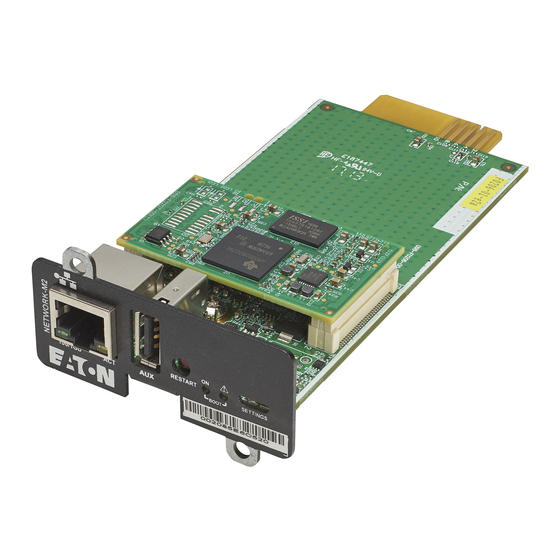
Front panel connectors and LED indicators 7 Information 7.1 Front panel connectors and LED indicators Name Description Network connector Ethernet port Network speed LED Flashing green sequences: • 1 flash — Port operating at 10Mbps • 2 flashes — Port operating at 100Mbps •…
-
Page 211: Specifications/Technical Characteristics
Specifications/Technical characteristics Boot LEDs Solid green and flashing red — Network Module is starting boot sequence. Settings/UPS data Configuration port. connector Access to Network Module’s web interface through RNDIS (Emulated Network port). Access to the Network Module console through Serial (Emulated Serial port). 7.2 Specifications/Technical characteristics Physical characteristics Dimensions (wxdxh)
-
Page 212: Default Settings And Possible Parameters
Default settings and possible parameters 7.3 Default settings and possible parameters 7.3.1 Settings Default settings and possible parameters — General Default setting Possible parameters System details Location — empty Location — 31 characters maximum Contact — empty Contact — 255 characters maximum System name — empty System name —…
-
Page 213
Default settings and possible parameters SMTP server authentication — disabled SMTP server authentication — disable/enable (Username/Password — 128 characters maximum) Port — 25 Port — x-xxx Default sender address — device @networkcard.com Sender address — 128 characters maximum Hide IP address from the email body — disabled Hide IP address from the email body —… -
Page 214
Default settings and possible parameters Default settings and possible parameters — Remote users Default setting Possible parameters LDAP Configure Configure • Active – No • Active – No/yes • Security • Security SSL – SSL SSL – None/Start TLS/SSL Verify server certificate –… -
Page 215
Default settings and possible parameters RADIUS Configure Configure • Active – No • Active – Yes/No • Retry number – 0 • Retry number – 0 to 128 • Primary server • Primary server Name – blank Name – 128 characters maximum Secret –… -
Page 216
Default settings and possible parameters Default settings and possible parameters — Network & Protocol Default setting Possible parameters IPV4 Mode — DHCP Mode — DHCP/Manual (Address/Netmask/Gateway) IPV6 Enable — checked Enabled — Active/Inactive Mode — DHCP Mode — DHCP/Manual (Address/Prefix/Gateway) DNS/DHCP Hostname —… -
Page 217
Default settings and possible parameters Using unicode byte order mask (BOM) – disable/ enable Default settings and possible parameters — SNMP Default setting Possible parameters SNMP Activate SNMP — disabled Activate SNMP — disable/enable Port — 161 Port — x-xxx SNMP V1 — disabled SNMP V1 —… -
Page 218
Port — 502 Port — x-xxx Mapping configuration No mapping Name – 128 characters maximum Map – Eaton ModbusMS compatible Transport – RTU/TCP Device ID – from 1 to 247 Access – None/Read only/Read/Write Illegal read behaviour – Return exception/Return zeros Coil/register base address shift –… -
Page 219: Meters
Default settings and possible parameters 7.3.2 Meters Default settings and possible parameters — Meters Default setting Possible parameters Meters/Logs Log measures every — 60s Log measures every — 3600s maximum 7.3.3 Sensors alarm configuration Default settings and possible parameters — Environment Alarm configuration Default setting Possible parameters Temperature…
-
Page 220: User Profile
Default settings and possible parameters 7.3.4 User profile Default settings and possible parameters — User profile Default setting Possible parameters Profile Account details: Account details: • Full name — Administrator • Full name — 128 characters maximum • Email —…
-
Page 221: Access Rights Per Profiles
Access rights per profiles 7.4 Access rights per profiles 7.4.1 Home Administrator Operator Viewer Home 7.4.2 Meters Administrator Operator Viewer Meters Battery health: Launch test/Abort Logs configuration 7.4.3 Controls Administrator Operator Viewer Control 7.4.4 Protection Administrator Operator Viewer Protection/Scheduled shutdowns Administrator Operator Viewer…
-
Page 222: Settings
Access rights per profiles Environment/Information 7.4.6 Settings Administrator Operator Viewer General Administrator Operator Viewer Local users Administrator Operator Viewer Remote users Administrator Operator Viewer Network & Protocols Administrator Operator Viewer SNMP Administrator Operator Viewer Modbus* *for INDGW only Administrator Operator Viewer Certificate…
-
Page 223: Legal Information
Access rights per profiles 7.4.8 Legal information Administrator Operator Viewer Legal information 7.4.9 Alarms Administrator Operator Viewer Alarm list Export Clear 7.4.10 User profile Administrator Operator Viewer User profile 7.4.11 Contextual help Administrator Operator Viewer Contextual help Full documentation 7.4.12 CLI commands Administrator Operator Viewer…
-
Page 224: List Of Event Codes
List of event codes modbus_statistics* *for INDGW only Administrator Operator Viewer netconf (read-only) (read-only) Administrator Operator Viewer ping ping6 Administrator Operator Viewer reboot Administrator Operator Viewer save_configuration restore_configuration Administrator Operator Viewer sanitize Administrator Operator Viewer ssh-keygen Administrator Operator Viewer time (read-only) (read-only)
-
Page 225
List of event codes To retrieve System logs, navigate to Contextual help>>>Maintenance>>>System logs section and press the Download System logs button. Below codes are the one to be used to add «Exceptions on events notification» on email sending configurations. Some zeros maybe added in front of the code when displayed in emails or logs. 7.5.1.1 Critical Code Severity… -
Page 226
List of event codes 1000D00 Warning Settings restoration error logSystem.csv 7.5.1.3 Info Code Severity Log message File 0300D00 Notice User action — sanitization launched logSystem.csv 0A00500 Notice Network module sanitized logUpdate.csv 0A00900 Notice Network module bootloader upgrade success <f/w: xx.yy.zzzz> logUpdate.csv 0A00B00 Notice… -
Page 227
List of event codes 0100B00 Notice Syslog is stopping logSystem.csv 0100D00 Notice Network module is booting logSystem.csv 0100E00 Notice Network module is operating logSystem.csv 0100F00 Notice Network module is starting shutdown sequence logSystem.csv 0101000 Notice Network module is ending shutdown sequence logSystem.csv 0101400 Notice… -
Page 228: Ups(Hid) Alarm Log Codes
List of event codes 7.5.2 UPS(HID) alarm log codes This table applies to all UPS except to the 9130 UPS. To retrieve Alarm logs, navigate to Contextual help>>>Alarms section and press the Download alarms button. Below codes are the one to be used to add «Exceptions on events notification» on email sending configurations. Some zeros maybe added in front of the code when displayed in emails or logs.
-
Page 229
List of event codes Critical Parallel negative power Parallel power OK Reduce output load Critical Calibration fault Calibration OK Service required Critical Load unprotected Load protected 7.5.2.2 Warning Code Severity Active message Non-active message Advice Warning On battery No more on battery Warning Fan fault Fan OK… -
Page 230
List of event codes Warning Max charger voltage Charger voltage OK Service required Warning Min charger voltage Charger voltage OK Service required Warning Battery fuse fault Battery fuse OK Service required Warning Battery fuse fault Battery fuse OK Service required Warning Battery low state of charge Battery state of charge OK… -
Page 231
List of event codes Warning Compatibility failure Compatibility OK Service required Warning Output over current No output over current Reduce output load Warning Output frequency out of range Output frequency in range Service required Warning Output voltage too high Output voltage OK Service required Warning Output voltage too low… -
Page 232: 9130 Ups(Xcp) Alarm Log Codes
List of event codes 7.5.3 9130 UPS(XCP) alarm log codes Use this table for 9130 UPS. To retrieve Alarm logs, navigate to Contextual help>>>Alarms section and press the Download alarms button. Below codes are the one to be used to add «Exceptions on events notification» on email sending configurations. Some zeros maybe added in front of the code when displayed in emails or logs.
-
Page 233
List of event codes 2325 Critical Bypass overload No bypass overload 2328 Critical Bypass thermal overload Bypass thermal OK 2364 Critical Internal failure End of internal failure 2402 Critical Parallel UPS not compatible Parallel UPS compatibility OK 281E Critical Load unprotected — 7.5.3.2 Warning Code… -
Page 234
List of event codes 2225 Warning Parallel UPS redundancy lost Parallel UPS redundancy OK 2231 Warning DC bus unbalanced DC bus OK 2240 Warning Parallel UPS communication lost Parallel UPS communication OK 2306 Warning Bypass breaker open Bypass breaker closed 2326 Warning Bypass phase out range… -
Page 235: Ats Alarm Log Codes
List of event codes 7.5.4 ATS alarm log codes To retrieve Alarm logs, navigate to Contextual help>>>Alarms section and press the Download alarms button. Below codes are the one to be used to add «Exceptions on events notification» on email sending configurations. Some zeros maybe added in front of the code when displayed in emails or logs.
-
Page 236
List of event codes 7.5.4.3 Good Alarms with a severity set as Good are not taken into account into the counter of active alarms. Code Severity Active message Non-active message Advice Good Source 1 used to power the load Source 1 not used to power the load — Good Source 2 used to power the load… -
Page 237: Emp Alarm Log Codes
List of event codes 7.5.5 EMP alarm log codes To retrieve Alarm logs, navigate to Contextual help>>>Alarms section and press the Download alarms button. Below codes are the one to be used to add «Exceptions on events notification» on email sending configurations. Some zeros maybe added in front of the code when displayed in emails or logs.
-
Page 238: Network Module Alarm Log Codes
List of event codes 7.5.6 Network module alarm log codes To retrieve Alarm logs, navigate to Contextual help>>>Alarms section and press the Download alarms button. Below codes are the one to be used to add «Exceptions on events notification» on email sending configurations. Some zeros maybe added in front of the code when displayed in emails or logs.
-
Page 239: Snmp Traps
SNMP traps 7.5.6.2.3 Alarms Code Severity Active message Non-active message Advice 1302 Info Alarms: the number of alarms is Alarms: the number of alarms is It is recommended to high and above 5 000 back to normal Export and Clear the alarm log.
-
Page 240: Ats Mib
SNMP traps Alarm oid at : Description when trap 3 Description when trap 4 .1.3.6.1.2.1.33.1.6.3.x .1.3.6.1.2.1.33.1.6.3.20 Communication lost Communication recovered .1.3.6.1.2.1.33.1.6.3.23 Shutdown imminent Shutdown canceled 7.6.1.2 Xups Mib traps This information is for reference only. Trap oid : Trap message at oid : .1.3.6.1.4.1.534.1.11.4.1.0.x .1.3.6.1.4.1.534.1.11.3.0 .1.3.6.1.4.1.534.1.11.4.1.0.3…
-
Page 241: Sensor Mib
SNMP traps Trap oid : Trap description .1.3.6.1.4.1.534.10.2.10.x .1.3.6.1.4.1.534.10.2.10.1 Communication lost .1.3.6.1.4.1.534.10.2.10.2 Communication recovered .1.3.6.1.4.1.534.10.2.10.3 Output powered .1.3.6.1.4.1.534.10.2.10.4 Output not powered .1.3.6.1.4.1.534.10.2.10.5 Overload .1.3.6.1.4.1.534.10.2.10.6 No overload .1.3.6.1.4.1.534.10.2.10.7 Internal failure .1.3.6.1.4.1.534.10.2.10.8 No internal failure .1.3.6.1.4.1.534.10.2.10.9 Source 1 normal .1.3.6.1.4.1.534.10.2.10.10 Source 1 out of range .1.3.6.1.4.1.534.10.2.10.11 Source 2 normal .1.3.6.1.4.1.534.10.2.10.12…
-
Page 242: Cli
CLI 7.7 CLI CLI can be accessed through: • • Serial terminal emulation (refer to section Servicing the Network Management Module>>>Installing the Network Module>>>Accessing the card through serial terminal emulation). It is intended mainly for automated configuration of the network and time settings of the network card. It can also be used for troubleshooting and remote reboot/reset of the network interface in case the web user interface is not accessible.
-
Page 243: Get Release Info
CONTEXT SENSITIVE HELP [?] — Display context sensitive help. This is either a list of possible command completions with summaries, or the full syntax of the current command. A subsequent repeat of this key, when a command has been resolved, will display a detailed reference. …
-
Page 244: History
CLI 7.7.3.3 Specifics 7.7.3.4 Access rights per profiles Administrator Operator Viewer get release info 7.7.4 history 7.7.4.1 Description Displays recent commands executed on the card. 7.7.4.2 Help history <cr> Display the current session’s command line history(by default display last commands) <Unsigned integer> Set the size of history list (zero means unbounded).
-
Page 245
7.7.5.2 Help Usage: ldap-test <command> [OPTION]… Test LDAP configuration. Commands: ldap-test -h, —help, Display help page ldap-test —checkusername <username> [—primary|—secondary] [-v] Check the user can be retrieve from the LDAP server <username> Remote username to test —primary Force the test to use primary server (optional) —secondary Force the test to use secondary server (optional) -
Page 246: Logout
CLI 7.7.6 logout 7.7.6.1 Description Logout the current user. 7.7.6.2 Help logout <cr> logout the user 7.7.6.3 Specifics 7.7.6.4 Access rights per profiles Administrator Operator Viewer logout 7.7.7 maintenance 7.7.7.1 Description Creates a maintenance report file which may be handed to the technical support. 7.7.7.2 Help maintenance <cr>…
-
Page 247: Modbus_Statistics
7.7.8.1 Description modbus_message_display restarts the server and displays Modbus message. This command allow you to verifiy that Modbus server is working as expected. 7.7.8.2 Help modbus_message_display —help Restart server and display modbus message Restart server and display modbus message 7.7.8.3 Specifics 7.7.8.4 Access rights per profiles Administrator Operator…
-
Page 248: Netconf
CLI 7.7.9.3 Specifics 7.7.9.4 Access rights per profiles Administrator Operator Viewer modbus_statistics* *for INDGW only 7.7.10 netconf 7.7.10.1 Description Tools to display or change the network configuration of the card. 7.7.10.2 Help For Viewer and Operator profiles: netconf -h Usage: netconf [OPTION]…
-
Page 249
netconf -h Usage: netconf [OPTION]… Display network information and change configuration. -h, —help display help page -l, —lan display Link status and MAC address -d, —domain display Domain mode, FQDN, Primary and Secondary DNS -4, —ipv4 display IPv4 Mode, Address, Netmask and Gateway … -
Page 250: Ping And Ping6
CLI 7.7.10.3 Examples of usage -> Display Link status and MAC address netconf -l -> Set Auto negotiation to Link netconf -s auto -> Set custom hostname netconf -f hostname ups-00-00-00-00-00-00 -> Set Adress, Netmask and Gateway netconf -i manual 192.168.0.1 255.255.255.0 192.168.0.2 ->…
-
Page 251: Reboot
7.7.11.3 Specifics 7.7.11.4 Access rights per profiles Administrator Operator Viewer ping ping6 7.7.12 reboot 7.7.12.1 Description Tool to Reboot the card. 7.7.12.2 Help Usage: reboot [OPTION] <cr> Reboot the card —help Display help —withoutconfirmation Reboot the card without confirmation 7.7.12.3 Specifics 7.7.12.4 Access rights per profiles Administrator Operator…
-
Page 252: Sanitize
CLI 7.7.13.3 Examples of usage 7.7.13.3.1 From a linux host: Save over SSH: sshpass -p $PASSWORD ssh $USER@$CARD_ADDRESS save_configuration -p $PASSPHRASE> $FILE Restore over SSH: cat $FILE | sshpass -p $PASSWORD ssh $USER@$CARD_ADDRESS restore_configuration -p $PASSPHRASE 7.7.13.3.2 From a Windows host: Save over SSH: plink …
-
Page 253: Ssh-Keygen
7.7.15 ssh-keygen 7.7.15.1 Description Command used for generating the ssh keys. 7.7.15.2 Help ssh-keygen -h, —help Display help <cr> Renew SSH keys 7.7.15.3 Specifics 7.7.15.4 Access rights per profiles Administrator Operator Viewer ssh-keygen 7.7.16 time 7.7.16.1 Description Command used to display or change time and date. 7.7.16.2 Help For Viewer and Operator profiles: time -h…
-
Page 254: Traceroute And Traceroute6
CLI time -h Usage: time [OPTION]… Display time and date, change time and date. -h, —help display help page -p, —print display date and time in YYYYMMDDhhmmss format -s, —set <mode> Mode values: — set date and time (format YYYYMMDDhhmmss) …
-
Page 255: Whoami
7.7.17.3 Specifics 7.7.17.4 Access rights per profiles Administrator Operator Viewer traceroute traceroute6 7.7.18 whoami 7.7.18.1 Description whoami displays current user information: • Username • Profile • Realm 7.7.18.2 Specifics 7.7.18.3 Access rights per profiles Administrator Operator Viewer whoami 7.7.19 email-test 7.7.19.1 Description mail-test sends test email to troubleshoot SMTP issues.
-
Page 256: Systeminfo_Statistics
CLI 7.7.19.3 Specifics 7.7.19.4 Access rights per profiles Administrator Operator Viewer email-test 7.7.20 systeminfo_statistics 7.7.20.1 Description Displays the following system information usage: usage : % upSince : date since the system started total: MB free: MB used: MB tmpfs: temporary files usage (MB) Flash user data …
-
Page 257
7.7.21.2 Help certificates <target> <action> <service_name> <target> : — local <action> : — print: provides a given certificate detailed information. — revoke: revokes a given certificate. — export: returns a given certificate contents. — import: upload a given certificate the server CSR. This will replace the CSR with the certificate given. -
Page 258: Legal Information
Copyright © 2020 Eaton. This firmware is confidential and licensed under Eaton Proprietary License (EPL or EULA). This firmware is not authorized to be used, duplicated, or disclosed to anyone without the prior written permission of Eaton. Limitations, restrictions and exclusions of the Eaton applicable standard terms and conditions, such as its EPL and EULA, apply.
-
Page 259: Acronyms And Abbreviations
Acronyms and abbreviations 7.9 Acronyms and abbreviations AC: Alternating current. ATS: Automatic transfer switch is an electrical switch that switches a load between two sources. AVR: Automatic Voltage Regulation provides stable voltage to keep equipment running in the optimal range. BMS: A Battery Management System is any electronic system that manages li-ion battery. bps: bit per second BOM: In Syslog, placing an encoded Byte Order Mark at the start of a text stream can indicates that the text is Unicode and identify the encoding scheme used.
-
Page 260
Acronyms and abbreviations MAC: A media access control address of a computer is a unique identifier assigned to network interfaces for communications at the data link layer of a network segment. MIB: A management information base is a database used for managing the entities in a communication network. Most often associated with the Simple Network Management Protocol (SNMP). -
Page 261
Acronyms and abbreviations Information – 261… -
Page 262: Troubleshooting
Action not allowed in Control/Schedule/Power outage policy 8 Troubleshooting 8.1 Action not allowed in Control/Schedule/Power outage policy 8.1.1 Symptom Below message is displayed when you access the Control, Schedule or Power outage policy page. This action is not allowed by the UPS. To enable it, please refer to the user manual of the UPS and its instructions on how to configure the UPS settings and allow remote commands.
-
Page 263: Action
EMP detection fails at discovery stage 8.3.3 Action In the server system BIOS, change the setting for Automatic Power ON to «Enabled». 8.4 EMP detection fails at discovery stage In the Network Module, in Contextual help>>>Environment>>>Commissioning/Status, EMPs are missing in the Sensor commissioning table.
-
Page 264: How Do I Log In If I Forgot My Password
How do I log in if I forgot my password? Refer to the section Contextual help>>>Maintenance>>>Services>>>Reboot. 2- Launch the discovery. 8.5 How do I log in if I forgot my password? 8.5.1 Action • Ask your administrator for password initialization. • If you are the main administrator, your password can be reset manually by following steps described in the Servicing the Network Management Module>>>Recovering main administrator password.
-
Page 265: Action #2
During the selected timeframe, new agent connections to the Network Module are automatically trusted and accepted. STEP 4: Action on the agent (IPP/IPM) while the time to accepts new agents is running on the Network Module Remove the Network module certificate file(s) *.0 that is (are) located in the folder Eaton\IntelligentPowerProtector\configs\tls. 8.7 LDAP configuration/commissioning is not working Refer to the section Servicing the Network Management Module>>>Commissioning/Testing…
-
Page 266
The alarm list has been cleared after an upgrade 8.9.2 Symptom SNMPv3 connectivity is not properly working after a restore settings on a 1.7.0 version or above. 8.9.3 Cause The SNMPv3 was configured prior to 1.7.0. In that case, SNMPv3 configuration is not well managed by the Save and by the Restore settings. 8.9.4 Action Reconfigure your SNMPv3 users and passwords on versions 1.7.0 or above and Save the settings. -
Page 267
Web user interface is not up to date after a FW upgrade 8.11.2 Action Recover the IP address and connect to the card. Refer to Installing the Network Management Module>>>Accessing the Network Module>>>Finding and setting the IP address section. 8.12 Web user interface is not up to date after a FW upgrade 8.12.1 Symptom After an upgrade: •…
-
Page 1
UPS Network Management Card — Network-M2 User guide English 06/08/2018 1.4.2… -
Page 3
Google™ is a trademark of Google Inc. All other trademarks are properties of their respective companies. ©Copyright 2017 Eaton Corporation. All rights reserved. No part of this document may be reproduced in any way without the express written approval of Eaton Corporation. -
Page 4: Table Of Contents
1 Table of Contents Table of Contents ………………….4 Contextual Help………………….11 Login page 2.1.1 Logging in for the first time 2.1.1.1 1. Enter default password 2.1.1.2 2. Change default password 2.1.1.3 3. Accept license agreement 2.1.2 Troubleshooting login issues Home 2.2.1 Menu structure 2.2.2 Energy flow diagram 2.2.2.1…
-
Page 5
2.4.7.4 Trusted clients certificates 2.4.8 Email 2.4.8.1 Email sending configuration 2.4.8.2 SMTP 2.4.8.3 Default settings parameters and limitations 2.4.9 My preferences 2.4.9.1 Profile 2.4.9.2 Temperature 2.4.9.3 Date format 2.4.9.4 Time format 2.4.9.5 Language Meters 2.5.1 Power 2.5.1.1 Input 2.5.1.2 Output 2.5.2 Measure logs 2.5.2.1… -
Page 6
2.9.2 Alarm configuration (sensors) 2.9.2.1 Temperature 2.9.2.2 Humidity 2.9.2.3 Dry contacts 2.9.2.4 Default settings parameters and limitations 2.9.3 Information (sensors) 2.10 Legal information (footer) 2.10.1 Component list 2.10.2 Notice for our proprietary (i.e. non-Open source) elements 2.10.3 Availability of source code 2.11 Contextual and detailed help 2.11.1… -
Page 7
3.13.2.1 Target 3.13.2.2 Step 1: Installation setup 3.13.2.3 Step 2: Agent settings 3.13.2.4 Step 3: Power outage policy settings 3.13.3 Restart sequentially the IT equipment on utility recovery 3.13.3.1 Target 3.13.3.2 Step 1: Installation setup 3.13.3.3 Step 2: Power outage policy settings 3.14 Resetting username and password Securing the Network Management Module …………. -
Page 8
5.3.4 Defining EMPs address and termination 5.3.4.1 Manual addressing 5.3.5 Connecting an external contact device Commissioning the EMP 5.4.1 On the Network-M2 device Information …………………… 91 Front panel connectors and LED indicators Default settings parameters 6.2.1 Settings 6.2.1.1 General 6.2.1.2 Date &… -
Page 9
EMP detection fails at discovery stage 7.1.1 Symptoms 7.1.2 Possible cause 7.1.3 Action #1 7.1.4 Action #2 How do I log in if I forgot my password? 7.2.1 Action IPP is not able to communicate with the Network module 7.3.1 Symptoms 7.3.2 Possible cause… -
Page 10
Table of Contents – 10… -
Page 11: Contextual Help
Login page 2 Contextual Help 2.1 Login page The page language is set to English by default, but can be switched to browser language when it is managed. After navigating to the assigned IP address, accept the untrusted certificate on the browser. 2.1.1 Logging in for the first time 1. Enter default password As you are logging into the Network Module for the first time you must enter the factory set default username and password. •…
-
Page 12: Energy Flow Diagram
Home Settings Module settings: • General • Date & Time • Users • Network • Protocols • SNMP • Certificates • Email • My Preferences Alarms List of alarms with date and time Alarms download Meters Power quality measures: • Frequency •…
-
Page 13
Home Diagram elements description Description Possible states bols Green Yellow Black / White / Greyed Main utility Powered Out of nominal Not present range Unknown The equipment Normal In overload Not powered is protected and mode Unknown powered Buck through an AVR mode… -
Page 14
Home Line interactive diagram examples Normal mode Buck/Boost mode Battery mode Contextual Help – 14… -
Page 15: Online
Home Online Diagram elements description Description Possible states bols Green Yellow Black or white Main utility or Powered Out of nominal Not present second utility range Unknown Rectifier: convert Powered In overload In short Not powered AC power to DC circuit HE mode Unknown…
-
Page 16
Home Automatic Powered In overload In fault Not powered bypass (standby, Unknown auto bypass, forced bypass, high efficiency mode) Maintenance Powered Not powered bypass (optional) (maintenance Unknown bypass) Wiring Energy flow In overload No energy Out of nominal Unknown range Online diagram examples… -
Page 17: Top Bar
Home Mainte nance bypas mode 2.2.3 Top bar Current user/Logout Status Output power Battery status Alarms button Settings button 2.2.4 Details This view provides a summary of device identification information and nominal values: Name Model Location Firmware version Input Voltage Input Frequency Output Voltage Output Frequency The COPY TO CLIPBOARD button will copy the information to your clipboard so that it can be past. For example, you can copy and paste information into an email. 2.2.5 Outlet status Provides the status of the UPS outlets (ON/OFF) by load segmentation : Status (ON/OFF— Protected/Not protected/Not powered)
-
Page 18: Active Alarms
Alarms 2.2.6 Active Alarms Only active alarms are displayed, the Alarms icon will also display the number of active alarms. Alarms are sorted by date, alert level, time, and description. Note: To see the alarm history, press the Alarms button. 2.3 Alarms All alarms are displayed and sorted by date, with alert level, time, description, and status. • Alert level : Critical/Warning/Minor • Status : Active/Non-active Above 10 alarms, buttons First, Previous and Next appears to allow navigation in the Alarm list. Press the Download Alarms button to download the file. 2.3.1 Active alarm list with codes For details on alarm codes, see the Information>>>Alarm log codes sectionin the detailed help. 2.4 Settings 2.4.1 General Location…
-
Page 19: Manual: Manually Entering The Date And Time
Settings The current date and time appears in the footer at the bottom of the screen. You can set the time either manually or automatically. Manual: Manually entering the date and time 1. Select the time zone for your geographic area from the time zone pull-down menu or with the map. 2. Select the date and time. 3. Save the changes. Dynamic (NTP) : Synchronizing the date and time with an NTP server 1. Enter the IP address or host name of the NTP server in the NTP server field. 2. Select the time zone for your geographic area from the time zone pull-down menu or with the map. 3. Save the changes. Note: DST is managed based on the time zone. Default settings parameters and limitations …
-
Page 20: Actions
Settings Controls Protection Sensors Status Alarm configuration Information Card System information System logs Administration Sensors (commissioning) Legal information (footer) Contextual and detailed help Command Line Interface • Status – Status could take following values – Inactive/Locked/Password expired/Active Actions Press the New button to create up to ten new users. Remove Select a user and press the Delete button to remove it.
-
Page 21: Account Expiration
Settings Press Save after modifications. Account expiration To set the account expiration rules, apply the following restrictions: • Password expires after (in days). The main administrator password never expires. • Block account when invalid password is entered after (in number of attempts). The main administrator account will never block.
-
Page 22: Domain
Settings • Enter the gateway address. The gateway address allows connections to devices or hosts attached to different network segments. Dynamic (DHCP) • Select dynamic DHCP to configure network parameters by a BootP or DHCP server. If a response is not received from the server, the UPS Network Module boots with the last saved parameters from the most recent power up.
-
Page 23: Default Settings Parameters And Limitations
Settings Default settings parameters and limitations For details on default parameters and limitations, see the Information>>>Default settings parameters section in the detailed help. 2.4.5 Protocols This tab contains settings for communication protocols used to get information from the device through the network, such as https for web browser. HTTPS Only https is available. The default network port for https is 443. For additional security, the ports can be changed on this page. Press Save after modifications.
-
Page 24: Trap Receivers
Settings For a list of supported MIBs, see the Information>>>Specifications/Technical characteristics section in the detailed help. Press the Supported MIBs button to download the MIBs. Settings This screen allows an administrator to configure SNMP settings for computers that use the MIB to request information from the UPS Network Module. Default ports for SNMP are 161 (SNMP v1 and v3, set/get) and 162 (traps). These ports can be changed on the settings screen for additional security.
-
Page 25: Actions
Settings Actions 1. Press the New button to create new trap receivers. 2. Set following settings: • Status • Application name • Hostname or IP address • Port • Protocol • Trap community (V1) / User (V3) 3. Press the SAVE button. Remove Select a trap receiver and press the Delete button to remove it. Edit Press the pen icon to edit trap receiver information and access to its settings. Test all traps Press the Test all traps button to send the trap test to all trap receivers.
-
Page 26
Settings • Expiration • Status — valid, expires soon, or expired Actions Revoke This action will take the selected certificate out of use. Select the certificate to revoke, and then press the Revoke button. A confirmation window appear, press Continue to proceed, this operation cannot be recovered. Revoke will replace current certificate by a new self signed certificate. This may disconnect connected applications: — Web browsers — Shutdown application — Monitoring application… -
Page 27: Certificate Authorities (Ca)
Settings CSR must be signed with the CA, which is managed outside the card. Import certificate When the CSR is signed by the CA, it can be imported into the Network Module. When the import is complete, the new server certificate information is displayed in the table. Certificate authorities (CA) Manages CAs.
-
Page 28: Trusted Clients Certificates
Settings Actions Start Starts the pairing window during the selected timeframe or until it is stopped. Time countdown is displayed. Stop Stops the pairing window. Trusted clients certificates The table shows the following information for each trusted clients certificates. • Used for •…
-
Page 29: Smtp
Settings Edit Press the pen icon to edit email sending configuration and access to the following settings: • Active • Configuration name • Email address • Notify on events – Severity level/Attach logs/Exceptions on events notification • Periodic report – Active/Recurrence/Starting/Topic selection – Card/Devices SMTP SMTP is an internet standard for electronic email transmission. The following SMTP settings are configurable: •…
-
Page 30: Date Format
Meters • °F (Fareinheit) Date format • MM-DD-YYYY • YYY-MM-DD • DD-MM-YYY • MM-DD-YYYY • DD.MM.YYY • DD/MM/YYY • DD MM YYYY Time format • hh:mm:ss (24h) • hh:mm:ss (12h) Language • German • English • Spanish • French • Italian •…
-
Page 31: Measure Logs
Controls Measure logs Press the Download measures button to download the log file. If available, possible measures are listed below: • Input Voltage (V) • Input Frequency (Hz) • Bypass Voltage (V) • Bypass Frequency (Hz) • Output Voltage (V) • Output Frequency (Hz) •…
-
Page 32: Battery Test
Controls This control is available only if the status is not OFF and if there are no active commands running. • Switch ON This will switch ON the load or turn ON the online UPS. This control is available when the status is OFF, if there are no active commands running and if the Online UPS is on bypass.
-
Page 33: Protection
Protection This will shut off the load connected to the associated load segment. Protected applications are safely powered down. This control is available only if the status is not OFF and if there are no active commands running. • Safe reboot This will power down and then switch ON the load connected to the associated load segment.
-
Page 34: Agent List
After automatic acceptance, make sure that all listed agents belong to your infrastructure. If not, access may be revoked using the Delete button. For maximum security, Eaton recommend following one of the two methods on the certificate settings page: — import client certificates manually. — generate trusted certificate for both clients and Network Module using your own PKI.
-
Page 35: Actions
Protection Actions Delete When the agent is connected, the Delete function will not work correctly because the agent will keep on trying to re-connect. So connect to the software, remove the Network module from the Software nodes list (in the nodes list, right click on the Network module and click remove nodes).
-
Page 36: Power Outage Policy
Protection Note: The trigger in the diagram is the moment when the shutdown sequence starts and it is defined in the power outage policy section for each power source. 2.7.4 Power outage policy These setting are in conjuntion with the shutdown agents and control how the network module directs the shutdown of protected servers and appliances. It gives the possibility to prioritize and schedule shutdown actions so that the IT system is powered down in the correct order. For example, applications first, database servers next, and storage last.
-
Page 37
Protection On custom policy, if the 2 checkboxes are unchecked, only the last condition is taken into account. Settings examples All the following examples are using below agents settings. • Example 1: Maximize availability policy • Example 2: Immediate graceful shutdown policy Contextual Help – 37… -
Page 38
Protection • Example 3: Load shedding policy Settings Settings Contextual Help – 38… -
Page 39: On Low Battery Warning
Protection • Example 4: Custom policy Settings Settings On low battery warning In some cases, like a renewed power failure or failed battery, the capacity is much lower than anticipated. The UPS gives a Low battery warning when there is 2 — 3 minutes of estimated runtime left, depending on the UPS and its settings.
-
Page 40: Card
Card • Wait until UPS battery capacity exceeds a set percentage value in (%), and then automatically restart the UPS. — Then restart Group 1 after a set time in (s). — Then restart Group 2 after a set time in (s). Enable/Disable Each option listed above can be enabled or disabled with check-boxes. When disabled, the option will be greyed out. 2.8 Card 2.8.1 System information System information is an overview of the main Network Module information.
-
Page 41: Sanitization
• Active Version Displays the associated firmware version. Release date Displays the release date of the firmware. For better performance, security, and optimized features, Eaton recommends to upgrade the Network Module regularly. Installation date Displays when the firmware was installed in the Network Module. Activation date Displays when the firmware was activated in the Network Module.
-
Page 42: Reboot
Card For details on default settings, see the Information>>>Default settings parameters section in the detailed help. To sanitize the Network Module: 1. Click Sanitize. 2. A confirmation message displays, click Sanitize to confirm. Depending on your network configuration, the Network Module may restart with a different IP address. Only main administrator user will remain with default login and password.
-
Page 43: Sensors (Commissioning)
Card • User accounts (user settings, passwords, preferences) • Protection agents (agent list, agent settings) • Sensor settings (commissioning, alarm configuration) • SNMPv3 authentication and privacy keys To save the Network module settings: Click on Save Select the settings to exclude Click on Continue Restore …
-
Page 44: Actions
Sensors Actions Discover At first the table is empty, press the Discover button to lauch the sensor discovery process. If sensors are discovered, the table is populated accordingly Delete Select a sensor and press the Delete button to delete the sensor. When a sensor is deleted, all the commissioning informations are deleted. Define offsets Select the sensors. Press the Define offset button to adjust the temperature and humidity offsets of the selected sensors.
-
Page 45: Humidity Table
Sensors • Current temperature • Communication – Connected/Lost with dates Humidity table The table shows the following information for each sensors. • Name • Location • Current humidity • Communication – Connected/Lost with dates Dry contacts table The table shows the following information for dry contacts. •…
-
Page 46: Humidity
Sensors Set alarm threshold Select and directly change the setting in the table and then Save. When a warning threshold is reached, an alarm will be sent with a warning level. When a critical threshold is reached, an alarm will be sent with a critical level. Set Hysteresis Select and directly change the setting in the table and then Save. The hysteresis is the difference between the value where the alarm turns ON from turning OFF and the value where it turns OFF from turning ON.
-
Page 47: Default Settings Parameters And Limitations
Legal information (footer) Dry contacts alarm will be sent at the selected level. Default settings parameters and limitations For details on default parameters and limitations, see the Information>>>Default settings parameters section in the detailed help 2.9.3 Information (sensors) Sensor information is an overview of all the sensors informations connected to the Network Module. • Physical name • Model • Part number • Firmware version • UUID •…
-
Page 48: Access To Detailed Help
Contextual and detailed help Search feature is indexed, but when inside the contextual help section it won’t search in the detailed help sections. To get better results when searching, search inside the detailed help section. 2.11.2 Access to detailed help Press ? icon on the top right side of the page to access the contextual help.
-
Page 49: Servicing The Network Management Module
Unpacking the Network module 3 Servicing the Network Management Module 3.1 Unpacking the Network module The network module will include the following: • Network module • Quickstart • USB AM to Micro USB/M/5P 5ft Cable Packing materials must be disposed of in compliance with all local regulations concerning waste. Recycling symbols are printed on the packing materials to facilitate sorting.
-
Page 50: Accessing The Web Interface Through Network
Installing the Network Module 3.2.2 Accessing the web interface through Network Connecting the network cable Security settings in the Network Module may be in their default states. For maximum security, configure through a USB connection before connecting the network cable. Connect a standard gigabit compatible shielded ethernet cable (F/UTP or F/FTP) between the network connector on the Network Module and a network jack.
-
Page 51: Your Network Is Not Equipped With A Bootp/Dhcp Server
Installing the Network Module • To access the web interface through RNDIS, see the Accessing the web interface through RNDIS section. • Navigate to Settings>>>Network>>>IPV4. • Read the IPv4 settings. Your network is not equipped with a BOOTP/DHCP server Define from the configuration port The IP address can be defined by accessing the web interface through RNDIS. To access web interface through RNDIS, see the Accessing the web interface through RNDIS section.
-
Page 52
Installing the Network Module On some others it may fail then proceed to manual configuration. Manual configuration 1. In case Windows® OS fails to find driver automatically, go to the Windows control panel>Network and sharing center>Local area connection 2. Right click on the RNDIS local area connection and select Properties. 3. Select Internet Protocol Version 4 (TCP/IPv4)” and press the Properties button. Servicing the Network Management Module – 52… -
Page 53
Installing the Network Module 4. Then enter the configuration as below and validate (IP = 169.254.0.150 and mask = 255.255.255.0), click OK, then click on Close. Servicing the Network Management Module – 53… -
Page 54: Accessing The Card Through Serial Terminal Emulation
Installing the Network Module Accessing the web interface 1. Be sure that the UPS is powered on. 2. On the host computer, download the RNDIS_Serial.zip file from the website www.powerquality.eaton.com/Support/ and extract it. For more information, navigate to Accessing to the latest Network Module firmware/driver section. 3. Launch setProxy.bat to add 169.254.* in proxy’s exceptions list, if needed. 4. Launch a supported browser, the browser window appears. 6. Enter the user name in the User Name field. The default user name is admin. 7. Enter the password in the Password field. The default password is admin. 8. Click Sign In. The Network Module local web interface appears. 3.2.5 Accessing the card through serial terminal emulation Connecting the configuration cable 1.
-
Page 55: Manual Configuration Of The Serial Connection
Serial driver is used to emulate a serial connection from USB. After the card is connected to the PC, manual configuration of the driver is needed for Windows® OS to discover the serial connection. 1. On the host computer, download the RNDIS_Serial.zip file from the website www.powerquality.eaton.com/ Support/ and extract it. 2. Plug the USB cable and go to Windows® Device Manager. 3- Check the CDC Serial in the list, if it is with a yellow exclamation mark implying that driver has not been installed follow the steps 4-5-6-7 otherwise configuration is OK.
-
Page 56: Accessing The Card Through Serial
Accessing the card through Serial Use the console and get access to the card, refer to CLI section to get command instructions. 3.2.6 Configuring the UPS Network Module settings Use Eaton UPS Network Module web interface to configure the UPS Network Module. Main web interface menus are described below: Home page with overview of the UPS/Module status (Synoptic, Alarm, Meters, Load segments,…). Module settings (Date&Time, Users, Alerts, Network, Protocols, System logs, My Preferences, …).
-
Page 57: Pairing Agent To The Network Module
Pairing agent to the Network Module Entire UPS Control, Battery test, Load Segments control. Scheduled Shutdown, Protected Application, Agents Settings, Power Outage Policy. Sensors (only displayed when sensors have been discovered in card administration) Card administration (Firmware upgrade, reboot, save and restore, sensor commissioning,…) 3.3 Pairing agent to the Network Module Authentication and encryption of connections between the UPS network module and shutdown agents is based on matching certificates.
-
Page 58: Pairing With Manual Acceptance (Maximum Security)
4. Select the client.pem file previously saved, click Open. Communication with the agent is restored. 3.4 Accessing to the latest Network Module firmware/driver/script Download the latest Eaton Network Module firmware, driver or script from the Eaton website www.powerquality.eaton.com/Support/. 3.5 Upgrading the card firmware (Web interface / shell script) …
-
Page 59: Shell Script
Upgrading the card firmware (Web interface / shell script) 3.5.2 Shell script Prerequisite Shell script uses the following tools: sshpass, scp. To get it installed on your linux host, use the following commands. Debian/Ubuntu sudo apt-get install sshpass RedHat/Fedora/CentOS sudo install sshpass Make shell script executable:…
-
Page 60: Changing The Rtc Battery Cell
Changing the RTC battery cell Uncompress and flash upgrade inProgress(%):28 Uncompress and flash upgrade inProgress(%):44 Uncompress and flash upgrade inProgress(%):61 Uncompress and flash upgrade inProgress(%):78 Uncompress and flash upgrade inProgress(%):92 Uncompress and flash upgrade inProgress(%):100 Uncompress and flash upgrade inProgress(%):100 Uncompress and flash upgrade Executing post post_upgrade.sh script upgrade Upgrade done…
-
Page 61
Changing the RTC battery cell 6. Replace the Network Module and secure the screw, reconnect the Network cable if it was unplugged during the operation. 7. Connect the Network Module and set the date and time. For more information, see the Date & Time section. Servicing the Network Management Module – 61… -
Page 62: Changing The Language Of The Web Pages
Changing the language of the web pages 3.7 Changing the language of the web pages Update the language of the web page in the Settings menu. Navigate to Settings>>>My preferences>>>Language. 2. Select the language, and then press the Save button. The language of the login page is English by default or browser language when it is managed. 3.8 Checking the current firmware version of the Network Module Current firmware of the Network Module can be accessed in : •…
-
Page 63: Switching To Static Ip (Manual) / Changing Ip Address Of The Network Module
Switching to static IP (Manual) / Changing IP address of the Network Module 5. Change the position of switch number 3, this change is detected during power ON and the reset will be applied : Case 1 : Case 2 : …
-
Page 64: Powering Down/Up Applications (Examples)
Powering down/up applications (examples) LANs have an internal NTP server (Domain Controller, mail servers, Outlook servers are generally time servers too) but you can use a public ntp server like pool.ntp.org (after addition of the related rules to your firewall system). For more information, see the Date and Time section. 3.13 Powering down/up applications (examples) 3.13.1 Powering down IT system in a specific order Target Powering down applications first (when on battery for 30s), database servers next (3min after the…
-
Page 65: Step 2: Agent Settings
Powering down/up applications (examples) Step 2: Agent settings Objective Ensure IT solution is shutdown gracefully. Resulting setup 1. Install IPP Software on each servers (Application, Database servers, Storage) and register the UPS load segment as power source: • Applications: Group 1 • Database servers: Group 2 • Storage: Entire UPS 2. Pair agent to the Network Module (Pairing agent to the Network Module).
-
Page 66: Powering Down Non-Priority Equipment First
Powering down/up applications (examples) Storage is the last one to power down, its availability is maximized and its shutdown will end 30s before the end of backup time. 4. Set Group 1 and Group 2 to: load shedding policy. Applications must shutdown first so Group 1 has been set to start shutdown when on battery for 30s. Servers must shutdown second so Group 2 has been set to start shutdown when on battery for 210s, so 3min after the applications.
-
Page 67: Step 1: Installation Setup
Powering down/up applications (examples) Step 1: Installation setup Objective Use load segmentation provided by the UPS to independently control the power supply of each IT equipment categories (Applications, Database servers, Storage). Load segmentation also allows IT equipment to restart sequentially on utility recovery (Restart sequentially the IT equipment on utility recovery). Resulting setup UPS provides outlets (Group 1 and Group 2) and a primary output.
-
Page 68
Powering down/up applications (examples) For examples of Power outage policy, see the following sections: • Maximize availability policy example • Immediate graceful shutdown policy example • Load shedding policy examples • Custom policy examples 2. Enable policies of Primary, Group 1 and Group 2. 3. Set Primary and Group 1 to: custom policy and set it to end shutdown sequence 180s before the end of backup time. -
Page 69: Restart Sequentially The It Equipment On Utility Recovery
Powering down/up applications (examples) 3.13.3 Restart sequentially the IT equipment on utility recovery Target Restart the storage first (right after utility recovery), database servers next (2min after utility recovery) and applications last (3min after utility recovery). Step 1: Installation setup Objective Use load segmentation provided by the UPS to independently control the power supply of each IT equipment categories (Applications, Database servers, Storage).
-
Page 70: Resetting Username And Password
Resetting username and password 2. Enable the «Keep shutdown sequence running until the end and then restart (forced reboot)». 3. Enable the «Automatically restart the UPS when battery capacity exceeds» and set it to 0%. The storage will restart first, right after utility recovery without waiting the battery capacity to exceed a % limit. 4. Set Then Group 1 after to 120s. The database servers will restart 120s after the utility recovery. 5. Set Then Group 2 after to 60s. The database servers will restart 180s after the utility recovery.
-
Page 71: Securing The Network Management Module
4.1.1 Purpose The purpose of this section is to provide high-level guidance to help customers across industries and applications apply Eaton solutions for power management of electrical systems in accordance with current cybersecurity standards. This document is intended to provide an overview of key security features and practices to consider in order to meet industry recommended standards and best practices.
-
Page 72: Paths To The Control Network
Cybersecurity considerations for electrical distribution systems Paths to the control network The paths in above figure include: • External users accessing the network through the Internet • Misconfigured firewalls • Unsecure wireless routers and wired modems • Infected laptops located elsewhere that can access the network behind the firewall •…
-
Page 73: Designing For The Threat Vectors
Cybersecurity considerations for electrical distribution systems 4.1.6 Designing for the threat vectors Firewalls Firewalls provide the capability to add stringent and multifaceted rules for communication between various network segments and zones in an ICS network. They can be configured to block data from certain segments, while allowing the relevant and necessary data through.
-
Page 74
Cybersecurity considerations for electrical distribution systems Three-tier architecture for a secure control network Above figure shows that the control networks are divided into layers or zones based on control functions, which are then connected by conduits (connections between the zones) that provide security controls to: •… -
Page 75: Intrusion Detection And Prevention Systems (Idps)
Cybersecurity considerations for electrical distribution systems Intrusion detection and prevention systems (IDPS) These are systems that are primarily focused on identifying possible incidents in an ICS network, logging the information about them, attempting to stop them, and reporting them to ICS security administrators. Because these systems are critical in an ICS network, they are regular targets for attacks and securing them is extremely important.
-
Page 76: Security Policy And Procedures
Cybersecurity considerations for electrical distribution systems Security policy and procedures It is important to identify “asset owners,” and to develop policies and procedures for a cybersecurity program. These policies need to be practical and enforceable in order to be effective. Policies should also address access related issues, such as physical access, contractors, and vendors. Existing (traditional) IT standards and policies may not apply (or have not been considered) for control systems.
-
Page 77: Patch Management Planning And Procedures
Cybersecurity considerations for electrical distribution systems • Physical security • People and processes • Network security • Host security • Applications security (both internally developed and commercially off-the-shelf (COTS)) Patch management planning and procedures A patching and vulnerability management process should be established based on the timely awareness of issues and appropriate action.
-
Page 78: Acronyms
Cybersecurity considerations for electrical distribution systems 4.1.10 Acronyms COTS Commercially Off-the-Shelf Demilitarized Zone Denial of Service File Transfer Protocol Human Machine Interface Industrial Control Systems ICS-CERT Industrial Control Systems — Cyber EmergencyResponse Team IDPS Intrusion Detection and Prevention Systems Intrusion Detection Systems Intrusion Prevention Systems Information Technology National Vulnerability Database…
-
Page 79: Cybersecurity Recommended Secure Hardening Guidelines
“hardening” guidelines provide information to the users to securely deploy and maintain their product to adequately minimize the cybersecurity risks to their system. Eaton is committed to minimizing the Cybersecurity risk in its products and deploys cybersecurity best practices and latest cybersecurity technologies in its products and solutions; making them more secure, reliable and competitive for our customers. Eaton also offers Cybersecurity Best Practices whitepapers to its customers that can be referenced at www.eaton.com/cybersecurity…
-
Page 80: Physical Protection
Cybersecurity recommended secure hardening guidelines • Link status • MAC address • Configuration IPV4 • Status • Mode • Address • Netmask • Gateway Domain • Mode • FQDN • Primary DNS • Secondary DNS IPV6 • Status • Mode •…
-
Page 81: Authorization And Access Control
The device also provide multiple options to connect with the device i.e. SSH, SNMP,SMTP,HTTPS etc. Services like SNMPv1 are considered insecure and Eaton recommends disabling all such insecure services. • It is recommended to disable unused physical ports like USB and SD card.
-
Page 82: Logging And Event Management
— http://eaton.com/cybersecurity and patch through www.powerquality.eaton.com/Support/. Conduct regular Cybersecurity risk analyses of the organization /system. Eaton has worked with third-party security firms to perform system audits, both as part of a specific customer’s deployment and within Eaton’s own development cycle process. Eaton can provide guidance and support to your organization’s effort to perform regular cybersecurity audits or assessments. Plan for Business Continuity / Cybersecurity Disaster Recovery It’s a Cybersecurity best practice for organizations to plan for Business continuity. Establish an OT Business Continuity plan, periodically review and, where possible, exercise the established continuity plans.
-
Page 83: Configuring User Permissions Through Profiles
Configuring user permissions through profiles https://ics-cert.us-cert.gov/Standards-and-References [R4] National Institute of Technology (NIST) Interagency “Guidelines on Firewalls and Firewall Policy, NIST Special Publication 800-41”, October 2009: http://nvlpubs.nist.gov/nistpubs/Legacy/SP/nistspecialpublication800-41r1.pdf 4.3 Configuring user permissions through profiles The user profile can be defined when creating a new users or changed when modifying an existing one. Refer to the section Users in the settings. 4.4 Decommissioning the Network Management module With the increased frequency of reported data breaches, it’s becoming more and more necessary for companies to implement effective and reliable decommissioning policies and procedures in order to protect the data stored on retired IT equipment from falling into the wrong hands, or a data breach. …
-
Page 84: Servicing The Emp
Description and features 5 Servicing the EMP 5.1 Description and features The optional Environmental Monitoring Probe (EMP) enables you to collect temperature and humidity readings and monitor the environmental data remotely. You can also collect and retrieve the status of one or two dry contact devices (not included). You can monitor readings remotely using SNMP or a standard Web browser through the Network module.
-
Page 85: Mounting The Emp
Installing the EMP 5.3.1 Mounting the EMP The EMP includes magnets, cable ties slots and keyholes to enable multiple ways of mounting it on your installation. Bottom mounting capabilities: Side mounting • magnets • magnets • keyholes • tie wraps •…
-
Page 86: Wall Mounting With Screws Example
Installing the EMP Bottom mounting Side mounting Wall mounting with screws example To mount the EMP on the wall close to the rack, use the supplied screw and screw anchor. Then, mount the EMP on the screw and tighten it. Wall mounting with nylon fastener example To mount the EMP within the enclosure environment, attach one nylon fastener to the EMP and the other nylon fastener to an enclosure rail post.
-
Page 87: Cabling The First Emp To The Device
3- Connect the USB connector of the USB to RS485 converter cable to the Network-Module USB connector. Use the supplied tie wraps to secure the RS485 to USB cable connection. Example: EMP connection to the Network-M2 Servicing the EMP – 87…
-
Page 88: Daisy Chaining 3 Emps
RJ45 connector of the third EMP (FROM DEVICE). 3- Refer to next section for the EMPs addressing in daisy chain. Example: connection to the Network-M2 5.3.4 Defining EMPs address and termination Manual addressing Define different address for all the EMPs in the daisy-chain.
-
Page 89: Connecting An External Contact Device
• External contact device 2. Connect the return and signal input wires from device 2 to screw terminals 2- Tighten the corresponding tightening screws on top of the EMP to secure the wires. 5.4 Commissioning the EMP 5.4.1 On the Network-M2 device STEP 1: Connect to the Network Module Servicing the EMP – 89…
-
Page 90
Commissioning the EMP • On a network computer, launch a supported web browser. The browser window appears. • In the Address/Location field, enter: https://xxx.xxx.xxx.xxx/ where xxx.xxx.xxx.xxx is the IP address of the Network Module. • The log in screen appears. • Enter the user name in the User Name field. • Enter the password in the Password field. •… -
Page 91: Information
Front panel connectors and LED indicators 6 Information 6.1 Front panel connectors and LED indicators Name Description Network connector Ethernet port Network speed LED Flashing green sequences: • 1 flash — Port operating at 10Mbps • 2 flashes — Port operating at 100Mbps •…
-
Page 92: Default Settings Parameters
Default settings parameters Warning LED Solid red — Network Module is in error state. Boot LEDs Solid green and flashing red — Network Module is starting boot sequence. Settings/UPS data Configuration port. connector Access to Network Module’s web interface through RNDIS (Emulated Network port). Access to the Network Module console through Serial (Emulated Serial port).
-
Page 93: Network
Default settings parameters Minimum length — enabled (8) Minimum length — enable (6-32)/disable Password Minimum upper case — enabled (1) Minimum upper case — enable (0-32)/disable strength Minimum lower case — enabled (1) Minimum lower case — enable (0-32)/disable Minimum digit — enabled (1) Minimum digit — enable (0-32)/disable Special character — enabled (1) Special character — enable (0-32)/disable Password expires after — disabled Password expires after — disable/enable Account (1-99999) Main administrator password never expiration expires — disabled Main administrator password never expires — disable/enable Block account when invalid password is entered after — Block account when invalid password is disabled entered after — disable/enable (1-99) Main administrator account never Main administrator account never blocks —…
-
Page 94: Snmp
Default settings parameters SNMP Default setting Possible parameters Enable — disabled Enable — disable/enable SNMP Port — 161 Port — x-xxx SNMP V1 — disabled SNMP V1 — disable/enable • Community #1 — public • Community #1 — 128 characters maximum Status — Inactive Status — Inactive/Active Access — Read only Access — Read only • Community #2 — private • Community #2 — 128 characters maximum Status — Inactive Status — Inactive/Active Access — Read/Write Access — Read/Write SNMP V3 — enabled SNMP V3 — disable/enable • User #1 — readonly •…
-
Page 95: Email
Default settings parameters Email Default setting Possible parameters No email 5 configurations maximum Email sending Active — Active/Inactive configuration Configuration name — 128 characters maximum Email address — 128 characters maximum • Delegate email to Active — No/Yes Email addresses – List of emails Keep primary email address in copy – disable/enable Starting – Date and time Ending – Date and time • Notify on events Active — No/Yes On card events – Subscribe/Attach logs (Critical/Warning/Info) On devices events – Subscribe/Attach logs…
-
Page 96: My Preferences
Default settings parameters My preferences Default setting Possible parameters Edit user: Edit user: Profile • Full name — Administrator • Full name — 128 characters maximum • Email — blank • Email — 128 characters maximum • Phone — blank • Phone — 64 characters maximum • Organization — blank • Organization — 128 characters maximum °C (Celsius) °C (Celsius)/°F (Fahrenheit) Temperature MM-DD-YYYY…
-
Page 97
Default settings parameters Dry contacts Enabled — No Enabled — No/Yes Alarm severity – Warning Alarm severity – Info/Warning/Critical Information – 97… -
Page 98: Specifications/Technical Characteristics
Specifications/Technical characteristics 6.3 Specifications/Technical characteristics Physical characteristics Dimensions (wxdxh) 132 x 66 x 42 mm | 5.2 x 2.6 x 1.65 in Weight 70 g | 0.15 lb RoHS 100% compatible Storage Storage temperature -25°C to 70°C (14°F to 158°F) Ambient conditions Operating temperature 0°C to 70°C (32°F to 158°F)
-
Page 99: List Of Events Codes
List of events codes Settings/UPS data USB RNDIS Apipa compatible | IP address: 169.254.0.1 | Subnet mask: connector 255.255.0.0 *xUPS MIB | Standard IETF UPS MIB (RFC 1628) 6.4 List of events codes To get access to the Alarm log codes or the System log codes for email subscription, see the Alarm log codes and System log codes sections. 6.5 Alarm log codes …
-
Page 100
Alarm log codes Critical Rectifier short circuit Rectifier OK Reduce output load Critical DCDC converter failure DCDC converter OK Service required Critical Battery charger fault Battery charger OK Service required Critical Battery fuse fault Battery fuse OK Service required Critical Battery low Battery OK Critical… -
Page 101: Warning
Alarm log codes Critical Inverter thermal No power overload Reduce output overload load Critical Inverter voltage too low Inverter voltage OK Service required Critical Inverter voltage too high Inverter voltage OK Service required 6.5.2 Warning Code Severity Active message Non active message Advice Warning On battery…
-
Page 102: Info
Alarm log codes Warning Battery low voltage Battery OK Warning Battery voltage too high Battery voltage OK Warning Load not powered Load powered Warning Power overload No power overload Reduce output load Warning Overload alarm No overload Reduce output load 1032 Warning Protection: immediate…
-
Page 103: With Settable Severity
Alarm log codes 1016 Info Protection: sequential Protection: sequential shutdown scheduled shutdown canceled 1017 Info Protection: sequential Protection: sequential shutdown in progress shutdown completed 1100 Info Schedule: shutdown Schedule: shutdown date reached initiated 1101 Info Schedule: restart date Schedule: restart reached initiated Info…
-
Page 104: System Log Codes
System log codes 6.6 System log codes To retrieve System logs, navigate to Card>>>System logs section and press the Download System logs button. 6.6.1 Alert Code Severity Log message File 0801000 Alert User account — admin password reset to default logAccount.csv 6.6.2 Critical Code Severity Log message File 0E00400 Critical The [selfsign/PKI] signed certificate of the <service> logSystem.csv server is not valid 6.6.3 Error…
-
Page 105: Notice
System log codes 6.6.5 Notice Code Severity Log message File 0300D00 Notice User action — sanitization launched logSystem.csv 0A00500 Notice Network module sanitized logUpdate.csv 0A00900 Notice Network module bootloader upgrade success <f/w: logUpdate.csv xx.yy.zzzz> 0A00B00 Notice Network module bootloader upgrade started <f/w: logUpdate.csv xx.yy.zzzz>…
-
Page 106: Info
System log codes 6.6.6 Info Code Severity Log message File 0A00100 Info Network module upgrade success <f/w: xx.yy.zzzz> logUpdate.csv 0A00300 Info Network module upgrade started logUpdate.csv 0A00600 Info Network module file system integrity OK <f/w: logUpdate.csv xx.yy.zzzz> 0B00300 Info Time with NTP synchronized logSystem.csv 0B00600 Info…
-
Page 107: Snmp Trap Oid
SNMP trap oid 6.7 SNMP trap oid 6.7.1 Eaton XupsMIB trap oid and message: Trap oid: Message .1.3.6.1.4.1.534.1.11.4.1.0.x .1.3.6.1.4.1.534.1.11.4.1.0.3 Battery discharging .1.3.6.1.4.1.534.1.11.4.1.0.4 Battery low .1.3.6.1.4.1.534.1.11.4.1.0.5 No more on battery .1.3.6.1.4.1.534.1.11.4.1.0.6 Battery OK .1.3.6.1.4.1.534.1.11.4.1.0.7 Power overload .1.3.6.1.4.1.534.1.11.4.1.0.8 Internal failure .1.3.6.1.4.1.534.1.11.4.1.0.10 Inverter internal failure .1.3.6.1.4.1.534.1.11.4.1.0.11 Bypass mode .1.3.6.1.4.1.534.1.11.4.1.0.12…
-
Page 108: Cli
CLI .1.3.6.1.4.1.534.1.11.4.1.0.43 Sensor humidity is below/above critical threshold .1.3.6.1.4.1.534.1.11.4.1.0.48 Maintenance bypass 6.8 CLI CLI can be accessed through SSH. It is intended mainly for automated configuration of the network and time settings of the network card. It can also be used for troubleshooting and remote reboot/reset of the network interface in case the web user interface is not accessible.
-
Page 109: Examples Of Usage
-4, —ipv4 <mode> Mode values: manual <network> <mask> <gateway> set custom Network address, Netmask and Gateway dhcp automatically set Network Address, Netmask and Gateway Examples of usage • Display Link status and MAC address netconf -L • Set Auto negotiation to Link netconf -L auto • Set custom hostnamen netconf -d hostname ups-00-00-00-00-00-00 •…
-
Page 110: Examples Of Usage
6.9.1 Availability of Source Code The source code of open source components that are made available by their licensors may be obtained upon written express request by contacting network-m2-opensource@Eaton.com. Eaton reserves the right to charge minimal administrative costs, in compliance with the terms of the underlying open source licenses, when the situation requires.
-
Page 111: Notice For Our Proprietary (I.e. Non-Open Source) Elements
Legal Information pages, available from the HTML user interface of the present product. 6.9.3 Notice for our proprietary (i.e. non-Open source) elements Copyright © 2017 Eaton. This firmware is confidential and licensed under Eaton Proprietary License (EPL or EULA). This firmware is not authorized to be used, duplicated, or disclosed to anyone without the prior written permission of Eaton.
-
Page 112: Acronyms And Abbreviations
Acronyms and abbreviations 6.10 Acronyms and abbreviations AC: Alternating current. AVR: Automatic Voltage Regulation provides stable voltage to keep equipment running in the optimal range. CA: Certificate Authority CLI: Command Line Interface. Aim is to interact with the Network Module by using commands in the form of successive lines of text (command lines). CSR: Certificate Signing Request DC: Direct current.
-
Page 113
Acronyms and abbreviations SSH: Secure Shell is a cryptographic network protocol for operating network services securely over an unsecured network. TLS: Transport Layer Security (TLS) is cryptographic protocol that provide communications security over a computer network. TFTP: Trivial File Transfer Protocol (TFTP) is a simple lockstep File Transfer Protocol which allows a client to get a file from or put a file onto a remote host. UPS: An uninterruptible power supply is an electrical apparatus that provides emergency power to a load when the input power source or mains power fails. A UPS is typically used to protect hardware such as computers, data centers, telecommunication equipment or other electrical equipment where an unexpected power disruption could cause injuries, fatalities, serious business disruption or data loss. -
Page 114
Acronyms and abbreviations Information – 114… -
Page 115: Troubleshooting
EMP detection fails at discovery stage 7 Troubleshooting 7.1 EMP detection fails at discovery stage 7.1.1 Symptoms In the Network Module, in Card>>>Sensors, EMPs are missing in the Sensor commissioning table. 1. The EMPs orange RJ45 LEDs are not blinking. 2. The EMPs green RJ45 LED (FROM DEVICE) is not ON. 7.1.2 Possible cause 1.
-
Page 116: Possible Cause
IPP is not able to communicate with the Network module 7.3.2 Possible cause The IPP certificate is not yet valid for the Network Module. Certificates of IPP and the Network Module are not matching so that authentication and encryption of connections between the Network Module and the shutdown agents is not working.
-
Page 117: Password Change In My Preferences Is Not Working
During the selected timeframe, new agent connections to the Network Module are automatically trusted and accepted. STEP 4: Action on the agent (IPP) while the time to accepts new agents is running on the Network Module Remove the Network module certificate file(s) *.0 that is (are) located in the folder Eaton IntelligentPowerProtectorconfigstls. 7.4 Password change in My preferences is not working 7.4.1 Symptoms The password change shows «Invalid credentials» when I try to change my password in My preferences menu.
-
Page 1
UPS Network Management Card — Network-M2 User guide English 06/08/2018 1.4.2… -
Page 3
Google™ is a trademark of Google Inc. All other trademarks are properties of their respective companies. ©Copyright 2017 Eaton Corporation. All rights reserved. No part of this document may be reproduced in any way without the express written approval of Eaton Corporation. -
Page 4: Table Of Contents
1 Table of Contents Table of Contents ………………….4 Contextual Help………………….11 Login page 2.1.1 Logging in for the first time 2.1.1.1 1. Enter default password 2.1.1.2 2. Change default password 2.1.1.3 3. Accept license agreement 2.1.2 Troubleshooting login issues Home 2.2.1 Menu structure 2.2.2 Energy flow diagram 2.2.2.1…
-
Page 5
2.4.7.4 Trusted clients certificates 2.4.8 Email 2.4.8.1 Email sending configuration 2.4.8.2 SMTP 2.4.8.3 Default settings parameters and limitations 2.4.9 My preferences 2.4.9.1 Profile 2.4.9.2 Temperature 2.4.9.3 Date format 2.4.9.4 Time format 2.4.9.5 Language Meters 2.5.1 Power 2.5.1.1 Input 2.5.1.2 Output 2.5.2 Measure logs 2.5.2.1… -
Page 6
2.9.2 Alarm configuration (sensors) 2.9.2.1 Temperature 2.9.2.2 Humidity 2.9.2.3 Dry contacts 2.9.2.4 Default settings parameters and limitations 2.9.3 Information (sensors) 2.10 Legal information (footer) 2.10.1 Component list 2.10.2 Notice for our proprietary (i.e. non-Open source) elements 2.10.3 Availability of source code 2.11 Contextual and detailed help 2.11.1… -
Page 7
3.13.2.1 Target 3.13.2.2 Step 1: Installation setup 3.13.2.3 Step 2: Agent settings 3.13.2.4 Step 3: Power outage policy settings 3.13.3 Restart sequentially the IT equipment on utility recovery 3.13.3.1 Target 3.13.3.2 Step 1: Installation setup 3.13.3.3 Step 2: Power outage policy settings 3.14 Resetting username and password Securing the Network Management Module …………. -
Page 8
5.3.4 Defining EMPs address and termination 5.3.4.1 Manual addressing 5.3.5 Connecting an external contact device Commissioning the EMP 5.4.1 On the Network-M2 device Information …………………… 91 Front panel connectors and LED indicators Default settings parameters 6.2.1 Settings 6.2.1.1 General 6.2.1.2 Date &… -
Page 9
EMP detection fails at discovery stage 7.1.1 Symptoms 7.1.2 Possible cause 7.1.3 Action #1 7.1.4 Action #2 How do I log in if I forgot my password? 7.2.1 Action IPP is not able to communicate with the Network module 7.3.1 Symptoms 7.3.2 Possible cause… -
Page 10
Table of Contents – 10… -
Page 11: Contextual Help
Login page 2 Contextual Help 2.1 Login page The page language is set to English by default, but can be switched to browser language when it is managed. After navigating to the assigned IP address, accept the untrusted certificate on the browser. 2.1.1 Logging in for the first time 1. Enter default password As you are logging into the Network Module for the first time you must enter the factory set default username and password. •…
-
Page 12: Energy Flow Diagram
Home Settings Module settings: • General • Date & Time • Users • Network • Protocols • SNMP • Certificates • Email • My Preferences Alarms List of alarms with date and time Alarms download Meters Power quality measures: • Frequency •…
-
Page 13
Home Diagram elements description Description Possible states bols Green Yellow Black / White / Greyed Main utility Powered Out of nominal Not present range Unknown The equipment Normal In overload Not powered is protected and mode Unknown powered Buck through an AVR mode… -
Page 14
Home Line interactive diagram examples Normal mode Buck/Boost mode Battery mode Contextual Help – 14… -
Page 15: Online
Home Online Diagram elements description Description Possible states bols Green Yellow Black or white Main utility or Powered Out of nominal Not present second utility range Unknown Rectifier: convert Powered In overload In short Not powered AC power to DC circuit HE mode Unknown…
-
Page 16
Home Automatic Powered In overload In fault Not powered bypass (standby, Unknown auto bypass, forced bypass, high efficiency mode) Maintenance Powered Not powered bypass (optional) (maintenance Unknown bypass) Wiring Energy flow In overload No energy Out of nominal Unknown range Online diagram examples… -
Page 17: Top Bar
Home Mainte nance bypas mode 2.2.3 Top bar Current user/Logout Status Output power Battery status Alarms button Settings button 2.2.4 Details This view provides a summary of device identification information and nominal values: Name Model Location Firmware version Input Voltage Input Frequency Output Voltage Output Frequency The COPY TO CLIPBOARD button will copy the information to your clipboard so that it can be past. For example, you can copy and paste information into an email. 2.2.5 Outlet status Provides the status of the UPS outlets (ON/OFF) by load segmentation : Status (ON/OFF— Protected/Not protected/Not powered)
-
Page 18: Active Alarms
Alarms 2.2.6 Active Alarms Only active alarms are displayed, the Alarms icon will also display the number of active alarms. Alarms are sorted by date, alert level, time, and description. Note: To see the alarm history, press the Alarms button. 2.3 Alarms All alarms are displayed and sorted by date, with alert level, time, description, and status. • Alert level : Critical/Warning/Minor • Status : Active/Non-active Above 10 alarms, buttons First, Previous and Next appears to allow navigation in the Alarm list. Press the Download Alarms button to download the file. 2.3.1 Active alarm list with codes For details on alarm codes, see the Information>>>Alarm log codes sectionin the detailed help. 2.4 Settings 2.4.1 General Location…
-
Page 19: Manual: Manually Entering The Date And Time
Settings The current date and time appears in the footer at the bottom of the screen. You can set the time either manually or automatically. Manual: Manually entering the date and time 1. Select the time zone for your geographic area from the time zone pull-down menu or with the map. 2. Select the date and time. 3. Save the changes. Dynamic (NTP) : Synchronizing the date and time with an NTP server 1. Enter the IP address or host name of the NTP server in the NTP server field. 2. Select the time zone for your geographic area from the time zone pull-down menu or with the map. 3. Save the changes. Note: DST is managed based on the time zone. Default settings parameters and limitations …
-
Page 20: Actions
Settings Controls Protection Sensors Status Alarm configuration Information Card System information System logs Administration Sensors (commissioning) Legal information (footer) Contextual and detailed help Command Line Interface • Status – Status could take following values – Inactive/Locked/Password expired/Active Actions Press the New button to create up to ten new users. Remove Select a user and press the Delete button to remove it.
-
Page 21: Account Expiration
Settings Press Save after modifications. Account expiration To set the account expiration rules, apply the following restrictions: • Password expires after (in days). The main administrator password never expires. • Block account when invalid password is entered after (in number of attempts). The main administrator account will never block.
-
Page 22: Domain
Settings • Enter the gateway address. The gateway address allows connections to devices or hosts attached to different network segments. Dynamic (DHCP) • Select dynamic DHCP to configure network parameters by a BootP or DHCP server. If a response is not received from the server, the UPS Network Module boots with the last saved parameters from the most recent power up.
-
Page 23: Default Settings Parameters And Limitations
Settings Default settings parameters and limitations For details on default parameters and limitations, see the Information>>>Default settings parameters section in the detailed help. 2.4.5 Protocols This tab contains settings for communication protocols used to get information from the device through the network, such as https for web browser. HTTPS Only https is available. The default network port for https is 443. For additional security, the ports can be changed on this page. Press Save after modifications.
-
Page 24: Trap Receivers
Settings For a list of supported MIBs, see the Information>>>Specifications/Technical characteristics section in the detailed help. Press the Supported MIBs button to download the MIBs. Settings This screen allows an administrator to configure SNMP settings for computers that use the MIB to request information from the UPS Network Module. Default ports for SNMP are 161 (SNMP v1 and v3, set/get) and 162 (traps). These ports can be changed on the settings screen for additional security.
-
Page 25: Actions
Settings Actions 1. Press the New button to create new trap receivers. 2. Set following settings: • Status • Application name • Hostname or IP address • Port • Protocol • Trap community (V1) / User (V3) 3. Press the SAVE button. Remove Select a trap receiver and press the Delete button to remove it. Edit Press the pen icon to edit trap receiver information and access to its settings. Test all traps Press the Test all traps button to send the trap test to all trap receivers.
-
Page 26
Settings • Expiration • Status — valid, expires soon, or expired Actions Revoke This action will take the selected certificate out of use. Select the certificate to revoke, and then press the Revoke button. A confirmation window appear, press Continue to proceed, this operation cannot be recovered. Revoke will replace current certificate by a new self signed certificate. This may disconnect connected applications: — Web browsers — Shutdown application — Monitoring application… -
Page 27: Certificate Authorities (Ca)
Settings CSR must be signed with the CA, which is managed outside the card. Import certificate When the CSR is signed by the CA, it can be imported into the Network Module. When the import is complete, the new server certificate information is displayed in the table. Certificate authorities (CA) Manages CAs.
-
Page 28: Trusted Clients Certificates
Settings Actions Start Starts the pairing window during the selected timeframe or until it is stopped. Time countdown is displayed. Stop Stops the pairing window. Trusted clients certificates The table shows the following information for each trusted clients certificates. • Used for •…
-
Page 29: Smtp
Settings Edit Press the pen icon to edit email sending configuration and access to the following settings: • Active • Configuration name • Email address • Notify on events – Severity level/Attach logs/Exceptions on events notification • Periodic report – Active/Recurrence/Starting/Topic selection – Card/Devices SMTP SMTP is an internet standard for electronic email transmission. The following SMTP settings are configurable: •…
-
Page 30: Date Format
Meters • °F (Fareinheit) Date format • MM-DD-YYYY • YYY-MM-DD • DD-MM-YYY • MM-DD-YYYY • DD.MM.YYY • DD/MM/YYY • DD MM YYYY Time format • hh:mm:ss (24h) • hh:mm:ss (12h) Language • German • English • Spanish • French • Italian •…
-
Page 31: Measure Logs
Controls Measure logs Press the Download measures button to download the log file. If available, possible measures are listed below: • Input Voltage (V) • Input Frequency (Hz) • Bypass Voltage (V) • Bypass Frequency (Hz) • Output Voltage (V) • Output Frequency (Hz) •…
-
Page 32: Battery Test
Controls This control is available only if the status is not OFF and if there are no active commands running. • Switch ON This will switch ON the load or turn ON the online UPS. This control is available when the status is OFF, if there are no active commands running and if the Online UPS is on bypass.
-
Page 33: Protection
Protection This will shut off the load connected to the associated load segment. Protected applications are safely powered down. This control is available only if the status is not OFF and if there are no active commands running. • Safe reboot This will power down and then switch ON the load connected to the associated load segment.
-
Page 34: Agent List
After automatic acceptance, make sure that all listed agents belong to your infrastructure. If not, access may be revoked using the Delete button. For maximum security, Eaton recommend following one of the two methods on the certificate settings page: — import client certificates manually. — generate trusted certificate for both clients and Network Module using your own PKI.
-
Page 35: Actions
Protection Actions Delete When the agent is connected, the Delete function will not work correctly because the agent will keep on trying to re-connect. So connect to the software, remove the Network module from the Software nodes list (in the nodes list, right click on the Network module and click remove nodes).
-
Page 36: Power Outage Policy
Protection Note: The trigger in the diagram is the moment when the shutdown sequence starts and it is defined in the power outage policy section for each power source. 2.7.4 Power outage policy These setting are in conjuntion with the shutdown agents and control how the network module directs the shutdown of protected servers and appliances. It gives the possibility to prioritize and schedule shutdown actions so that the IT system is powered down in the correct order. For example, applications first, database servers next, and storage last.
-
Page 37
Protection On custom policy, if the 2 checkboxes are unchecked, only the last condition is taken into account. Settings examples All the following examples are using below agents settings. • Example 1: Maximize availability policy • Example 2: Immediate graceful shutdown policy Contextual Help – 37… -
Page 38
Protection • Example 3: Load shedding policy Settings Settings Contextual Help – 38… -
Page 39: On Low Battery Warning
Protection • Example 4: Custom policy Settings Settings On low battery warning In some cases, like a renewed power failure or failed battery, the capacity is much lower than anticipated. The UPS gives a Low battery warning when there is 2 — 3 minutes of estimated runtime left, depending on the UPS and its settings.
-
Page 40: Card
Card • Wait until UPS battery capacity exceeds a set percentage value in (%), and then automatically restart the UPS. — Then restart Group 1 after a set time in (s). — Then restart Group 2 after a set time in (s). Enable/Disable Each option listed above can be enabled or disabled with check-boxes. When disabled, the option will be greyed out. 2.8 Card 2.8.1 System information System information is an overview of the main Network Module information.
-
Page 41: Sanitization
• Active Version Displays the associated firmware version. Release date Displays the release date of the firmware. For better performance, security, and optimized features, Eaton recommends to upgrade the Network Module regularly. Installation date Displays when the firmware was installed in the Network Module. Activation date Displays when the firmware was activated in the Network Module.
-
Page 42: Reboot
Card For details on default settings, see the Information>>>Default settings parameters section in the detailed help. To sanitize the Network Module: 1. Click Sanitize. 2. A confirmation message displays, click Sanitize to confirm. Depending on your network configuration, the Network Module may restart with a different IP address. Only main administrator user will remain with default login and password.
-
Page 43: Sensors (Commissioning)
Card • User accounts (user settings, passwords, preferences) • Protection agents (agent list, agent settings) • Sensor settings (commissioning, alarm configuration) • SNMPv3 authentication and privacy keys To save the Network module settings: Click on Save Select the settings to exclude Click on Continue Restore …
-
Page 44: Actions
Sensors Actions Discover At first the table is empty, press the Discover button to lauch the sensor discovery process. If sensors are discovered, the table is populated accordingly Delete Select a sensor and press the Delete button to delete the sensor. When a sensor is deleted, all the commissioning informations are deleted. Define offsets Select the sensors. Press the Define offset button to adjust the temperature and humidity offsets of the selected sensors.
-
Page 45: Humidity Table
Sensors • Current temperature • Communication – Connected/Lost with dates Humidity table The table shows the following information for each sensors. • Name • Location • Current humidity • Communication – Connected/Lost with dates Dry contacts table The table shows the following information for dry contacts. •…
-
Page 46: Humidity
Sensors Set alarm threshold Select and directly change the setting in the table and then Save. When a warning threshold is reached, an alarm will be sent with a warning level. When a critical threshold is reached, an alarm will be sent with a critical level. Set Hysteresis Select and directly change the setting in the table and then Save. The hysteresis is the difference between the value where the alarm turns ON from turning OFF and the value where it turns OFF from turning ON.
-
Page 47: Default Settings Parameters And Limitations
Legal information (footer) Dry contacts alarm will be sent at the selected level. Default settings parameters and limitations For details on default parameters and limitations, see the Information>>>Default settings parameters section in the detailed help 2.9.3 Information (sensors) Sensor information is an overview of all the sensors informations connected to the Network Module. • Physical name • Model • Part number • Firmware version • UUID •…
-
Page 48: Access To Detailed Help
Contextual and detailed help Search feature is indexed, but when inside the contextual help section it won’t search in the detailed help sections. To get better results when searching, search inside the detailed help section. 2.11.2 Access to detailed help Press ? icon on the top right side of the page to access the contextual help.
-
Page 49: Servicing The Network Management Module
Unpacking the Network module 3 Servicing the Network Management Module 3.1 Unpacking the Network module The network module will include the following: • Network module • Quickstart • USB AM to Micro USB/M/5P 5ft Cable Packing materials must be disposed of in compliance with all local regulations concerning waste. Recycling symbols are printed on the packing materials to facilitate sorting.
-
Page 50: Accessing The Web Interface Through Network
Installing the Network Module 3.2.2 Accessing the web interface through Network Connecting the network cable Security settings in the Network Module may be in their default states. For maximum security, configure through a USB connection before connecting the network cable. Connect a standard gigabit compatible shielded ethernet cable (F/UTP or F/FTP) between the network connector on the Network Module and a network jack.
-
Page 51: Your Network Is Not Equipped With A Bootp/Dhcp Server
Installing the Network Module • To access the web interface through RNDIS, see the Accessing the web interface through RNDIS section. • Navigate to Settings>>>Network>>>IPV4. • Read the IPv4 settings. Your network is not equipped with a BOOTP/DHCP server Define from the configuration port The IP address can be defined by accessing the web interface through RNDIS. To access web interface through RNDIS, see the Accessing the web interface through RNDIS section.
-
Page 52
Installing the Network Module On some others it may fail then proceed to manual configuration. Manual configuration 1. In case Windows® OS fails to find driver automatically, go to the Windows control panel>Network and sharing center>Local area connection 2. Right click on the RNDIS local area connection and select Properties. 3. Select Internet Protocol Version 4 (TCP/IPv4)” and press the Properties button. Servicing the Network Management Module – 52… -
Page 53
Installing the Network Module 4. Then enter the configuration as below and validate (IP = 169.254.0.150 and mask = 255.255.255.0), click OK, then click on Close. Servicing the Network Management Module – 53… -
Page 54: Accessing The Card Through Serial Terminal Emulation
Installing the Network Module Accessing the web interface 1. Be sure that the UPS is powered on. 2. On the host computer, download the RNDIS_Serial.zip file from the website www.powerquality.eaton.com/Support/ and extract it. For more information, navigate to Accessing to the latest Network Module firmware/driver section. 3. Launch setProxy.bat to add 169.254.* in proxy’s exceptions list, if needed. 4. Launch a supported browser, the browser window appears. 6. Enter the user name in the User Name field. The default user name is admin. 7. Enter the password in the Password field. The default password is admin. 8. Click Sign In. The Network Module local web interface appears. 3.2.5 Accessing the card through serial terminal emulation Connecting the configuration cable 1.
-
Page 55: Manual Configuration Of The Serial Connection
Serial driver is used to emulate a serial connection from USB. After the card is connected to the PC, manual configuration of the driver is needed for Windows® OS to discover the serial connection. 1. On the host computer, download the RNDIS_Serial.zip file from the website www.powerquality.eaton.com/ Support/ and extract it. 2. Plug the USB cable and go to Windows® Device Manager. 3- Check the CDC Serial in the list, if it is with a yellow exclamation mark implying that driver has not been installed follow the steps 4-5-6-7 otherwise configuration is OK.
-
Page 56: Accessing The Card Through Serial
Accessing the card through Serial Use the console and get access to the card, refer to CLI section to get command instructions. 3.2.6 Configuring the UPS Network Module settings Use Eaton UPS Network Module web interface to configure the UPS Network Module. Main web interface menus are described below: Home page with overview of the UPS/Module status (Synoptic, Alarm, Meters, Load segments,…). Module settings (Date&Time, Users, Alerts, Network, Protocols, System logs, My Preferences, …).
-
Page 57: Pairing Agent To The Network Module
Pairing agent to the Network Module Entire UPS Control, Battery test, Load Segments control. Scheduled Shutdown, Protected Application, Agents Settings, Power Outage Policy. Sensors (only displayed when sensors have been discovered in card administration) Card administration (Firmware upgrade, reboot, save and restore, sensor commissioning,…) 3.3 Pairing agent to the Network Module Authentication and encryption of connections between the UPS network module and shutdown agents is based on matching certificates.
-
Page 58: Pairing With Manual Acceptance (Maximum Security)
4. Select the client.pem file previously saved, click Open. Communication with the agent is restored. 3.4 Accessing to the latest Network Module firmware/driver/script Download the latest Eaton Network Module firmware, driver or script from the Eaton website www.powerquality.eaton.com/Support/. 3.5 Upgrading the card firmware (Web interface / shell script) …
-
Page 59: Shell Script
Upgrading the card firmware (Web interface / shell script) 3.5.2 Shell script Prerequisite Shell script uses the following tools: sshpass, scp. To get it installed on your linux host, use the following commands. Debian/Ubuntu sudo apt-get install sshpass RedHat/Fedora/CentOS sudo install sshpass Make shell script executable:…
-
Page 60: Changing The Rtc Battery Cell
Changing the RTC battery cell Uncompress and flash upgrade inProgress(%):28 Uncompress and flash upgrade inProgress(%):44 Uncompress and flash upgrade inProgress(%):61 Uncompress and flash upgrade inProgress(%):78 Uncompress and flash upgrade inProgress(%):92 Uncompress and flash upgrade inProgress(%):100 Uncompress and flash upgrade inProgress(%):100 Uncompress and flash upgrade Executing post post_upgrade.sh script upgrade Upgrade done…
-
Page 61
Changing the RTC battery cell 6. Replace the Network Module and secure the screw, reconnect the Network cable if it was unplugged during the operation. 7. Connect the Network Module and set the date and time. For more information, see the Date & Time section. Servicing the Network Management Module – 61… -
Page 62: Changing The Language Of The Web Pages
Changing the language of the web pages 3.7 Changing the language of the web pages Update the language of the web page in the Settings menu. Navigate to Settings>>>My preferences>>>Language. 2. Select the language, and then press the Save button. The language of the login page is English by default or browser language when it is managed. 3.8 Checking the current firmware version of the Network Module Current firmware of the Network Module can be accessed in : •…
-
Page 63: Switching To Static Ip (Manual) / Changing Ip Address Of The Network Module
Switching to static IP (Manual) / Changing IP address of the Network Module 5. Change the position of switch number 3, this change is detected during power ON and the reset will be applied : Case 1 : Case 2 : …
-
Page 64: Powering Down/Up Applications (Examples)
Powering down/up applications (examples) LANs have an internal NTP server (Domain Controller, mail servers, Outlook servers are generally time servers too) but you can use a public ntp server like pool.ntp.org (after addition of the related rules to your firewall system). For more information, see the Date and Time section. 3.13 Powering down/up applications (examples) 3.13.1 Powering down IT system in a specific order Target Powering down applications first (when on battery for 30s), database servers next (3min after the…
-
Page 65: Step 2: Agent Settings
Powering down/up applications (examples) Step 2: Agent settings Objective Ensure IT solution is shutdown gracefully. Resulting setup 1. Install IPP Software on each servers (Application, Database servers, Storage) and register the UPS load segment as power source: • Applications: Group 1 • Database servers: Group 2 • Storage: Entire UPS 2. Pair agent to the Network Module (Pairing agent to the Network Module).
-
Page 66: Powering Down Non-Priority Equipment First
Powering down/up applications (examples) Storage is the last one to power down, its availability is maximized and its shutdown will end 30s before the end of backup time. 4. Set Group 1 and Group 2 to: load shedding policy. Applications must shutdown first so Group 1 has been set to start shutdown when on battery for 30s. Servers must shutdown second so Group 2 has been set to start shutdown when on battery for 210s, so 3min after the applications.
-
Page 67: Step 1: Installation Setup
Powering down/up applications (examples) Step 1: Installation setup Objective Use load segmentation provided by the UPS to independently control the power supply of each IT equipment categories (Applications, Database servers, Storage). Load segmentation also allows IT equipment to restart sequentially on utility recovery (Restart sequentially the IT equipment on utility recovery). Resulting setup UPS provides outlets (Group 1 and Group 2) and a primary output.
-
Page 68
Powering down/up applications (examples) For examples of Power outage policy, see the following sections: • Maximize availability policy example • Immediate graceful shutdown policy example • Load shedding policy examples • Custom policy examples 2. Enable policies of Primary, Group 1 and Group 2. 3. Set Primary and Group 1 to: custom policy and set it to end shutdown sequence 180s before the end of backup time. -
Page 69: Restart Sequentially The It Equipment On Utility Recovery
Powering down/up applications (examples) 3.13.3 Restart sequentially the IT equipment on utility recovery Target Restart the storage first (right after utility recovery), database servers next (2min after utility recovery) and applications last (3min after utility recovery). Step 1: Installation setup Objective Use load segmentation provided by the UPS to independently control the power supply of each IT equipment categories (Applications, Database servers, Storage).
-
Page 70: Resetting Username And Password
Resetting username and password 2. Enable the «Keep shutdown sequence running until the end and then restart (forced reboot)». 3. Enable the «Automatically restart the UPS when battery capacity exceeds» and set it to 0%. The storage will restart first, right after utility recovery without waiting the battery capacity to exceed a % limit. 4. Set Then Group 1 after to 120s. The database servers will restart 120s after the utility recovery. 5. Set Then Group 2 after to 60s. The database servers will restart 180s after the utility recovery.
-
Page 71: Securing The Network Management Module
4.1.1 Purpose The purpose of this section is to provide high-level guidance to help customers across industries and applications apply Eaton solutions for power management of electrical systems in accordance with current cybersecurity standards. This document is intended to provide an overview of key security features and practices to consider in order to meet industry recommended standards and best practices.
-
Page 72: Paths To The Control Network
Cybersecurity considerations for electrical distribution systems Paths to the control network The paths in above figure include: • External users accessing the network through the Internet • Misconfigured firewalls • Unsecure wireless routers and wired modems • Infected laptops located elsewhere that can access the network behind the firewall •…
-
Page 73: Designing For The Threat Vectors
Cybersecurity considerations for electrical distribution systems 4.1.6 Designing for the threat vectors Firewalls Firewalls provide the capability to add stringent and multifaceted rules for communication between various network segments and zones in an ICS network. They can be configured to block data from certain segments, while allowing the relevant and necessary data through.
-
Page 74
Cybersecurity considerations for electrical distribution systems Three-tier architecture for a secure control network Above figure shows that the control networks are divided into layers or zones based on control functions, which are then connected by conduits (connections between the zones) that provide security controls to: •… -
Page 75: Intrusion Detection And Prevention Systems (Idps)
Cybersecurity considerations for electrical distribution systems Intrusion detection and prevention systems (IDPS) These are systems that are primarily focused on identifying possible incidents in an ICS network, logging the information about them, attempting to stop them, and reporting them to ICS security administrators. Because these systems are critical in an ICS network, they are regular targets for attacks and securing them is extremely important.
-
Page 76: Security Policy And Procedures
Cybersecurity considerations for electrical distribution systems Security policy and procedures It is important to identify “asset owners,” and to develop policies and procedures for a cybersecurity program. These policies need to be practical and enforceable in order to be effective. Policies should also address access related issues, such as physical access, contractors, and vendors. Existing (traditional) IT standards and policies may not apply (or have not been considered) for control systems.
-
Page 77: Patch Management Planning And Procedures
Cybersecurity considerations for electrical distribution systems • Physical security • People and processes • Network security • Host security • Applications security (both internally developed and commercially off-the-shelf (COTS)) Patch management planning and procedures A patching and vulnerability management process should be established based on the timely awareness of issues and appropriate action.
-
Page 78: Acronyms
Cybersecurity considerations for electrical distribution systems 4.1.10 Acronyms COTS Commercially Off-the-Shelf Demilitarized Zone Denial of Service File Transfer Protocol Human Machine Interface Industrial Control Systems ICS-CERT Industrial Control Systems — Cyber EmergencyResponse Team IDPS Intrusion Detection and Prevention Systems Intrusion Detection Systems Intrusion Prevention Systems Information Technology National Vulnerability Database…
-
Page 79: Cybersecurity Recommended Secure Hardening Guidelines
“hardening” guidelines provide information to the users to securely deploy and maintain their product to adequately minimize the cybersecurity risks to their system. Eaton is committed to minimizing the Cybersecurity risk in its products and deploys cybersecurity best practices and latest cybersecurity technologies in its products and solutions; making them more secure, reliable and competitive for our customers. Eaton also offers Cybersecurity Best Practices whitepapers to its customers that can be referenced at www.eaton.com/cybersecurity…
-
Page 80: Physical Protection
Cybersecurity recommended secure hardening guidelines • Link status • MAC address • Configuration IPV4 • Status • Mode • Address • Netmask • Gateway Domain • Mode • FQDN • Primary DNS • Secondary DNS IPV6 • Status • Mode •…
-
Page 81: Authorization And Access Control
The device also provide multiple options to connect with the device i.e. SSH, SNMP,SMTP,HTTPS etc. Services like SNMPv1 are considered insecure and Eaton recommends disabling all such insecure services. • It is recommended to disable unused physical ports like USB and SD card.
-
Page 82: Logging And Event Management
— http://eaton.com/cybersecurity and patch through www.powerquality.eaton.com/Support/. Conduct regular Cybersecurity risk analyses of the organization /system. Eaton has worked with third-party security firms to perform system audits, both as part of a specific customer’s deployment and within Eaton’s own development cycle process. Eaton can provide guidance and support to your organization’s effort to perform regular cybersecurity audits or assessments. Plan for Business Continuity / Cybersecurity Disaster Recovery It’s a Cybersecurity best practice for organizations to plan for Business continuity. Establish an OT Business Continuity plan, periodically review and, where possible, exercise the established continuity plans.
-
Page 83: Configuring User Permissions Through Profiles
Configuring user permissions through profiles https://ics-cert.us-cert.gov/Standards-and-References [R4] National Institute of Technology (NIST) Interagency “Guidelines on Firewalls and Firewall Policy, NIST Special Publication 800-41”, October 2009: http://nvlpubs.nist.gov/nistpubs/Legacy/SP/nistspecialpublication800-41r1.pdf 4.3 Configuring user permissions through profiles The user profile can be defined when creating a new users or changed when modifying an existing one. Refer to the section Users in the settings. 4.4 Decommissioning the Network Management module With the increased frequency of reported data breaches, it’s becoming more and more necessary for companies to implement effective and reliable decommissioning policies and procedures in order to protect the data stored on retired IT equipment from falling into the wrong hands, or a data breach. …
-
Page 84: Servicing The Emp
Description and features 5 Servicing the EMP 5.1 Description and features The optional Environmental Monitoring Probe (EMP) enables you to collect temperature and humidity readings and monitor the environmental data remotely. You can also collect and retrieve the status of one or two dry contact devices (not included). You can monitor readings remotely using SNMP or a standard Web browser through the Network module.
-
Page 85: Mounting The Emp
Installing the EMP 5.3.1 Mounting the EMP The EMP includes magnets, cable ties slots and keyholes to enable multiple ways of mounting it on your installation. Bottom mounting capabilities: Side mounting • magnets • magnets • keyholes • tie wraps •…
-
Page 86: Wall Mounting With Screws Example
Installing the EMP Bottom mounting Side mounting Wall mounting with screws example To mount the EMP on the wall close to the rack, use the supplied screw and screw anchor. Then, mount the EMP on the screw and tighten it. Wall mounting with nylon fastener example To mount the EMP within the enclosure environment, attach one nylon fastener to the EMP and the other nylon fastener to an enclosure rail post.
-
Page 87: Cabling The First Emp To The Device
3- Connect the USB connector of the USB to RS485 converter cable to the Network-Module USB connector. Use the supplied tie wraps to secure the RS485 to USB cable connection. Example: EMP connection to the Network-M2 Servicing the EMP – 87…
-
Page 88: Daisy Chaining 3 Emps
RJ45 connector of the third EMP (FROM DEVICE). 3- Refer to next section for the EMPs addressing in daisy chain. Example: connection to the Network-M2 5.3.4 Defining EMPs address and termination Manual addressing Define different address for all the EMPs in the daisy-chain.
-
Page 89: Connecting An External Contact Device
• External contact device 2. Connect the return and signal input wires from device 2 to screw terminals 2- Tighten the corresponding tightening screws on top of the EMP to secure the wires. 5.4 Commissioning the EMP 5.4.1 On the Network-M2 device STEP 1: Connect to the Network Module Servicing the EMP – 89…
-
Page 90
Commissioning the EMP • On a network computer, launch a supported web browser. The browser window appears. • In the Address/Location field, enter: https://xxx.xxx.xxx.xxx/ where xxx.xxx.xxx.xxx is the IP address of the Network Module. • The log in screen appears. • Enter the user name in the User Name field. • Enter the password in the Password field. •… -
Page 91: Information
Front panel connectors and LED indicators 6 Information 6.1 Front panel connectors and LED indicators Name Description Network connector Ethernet port Network speed LED Flashing green sequences: • 1 flash — Port operating at 10Mbps • 2 flashes — Port operating at 100Mbps •…
-
Page 92: Default Settings Parameters
Default settings parameters Warning LED Solid red — Network Module is in error state. Boot LEDs Solid green and flashing red — Network Module is starting boot sequence. Settings/UPS data Configuration port. connector Access to Network Module’s web interface through RNDIS (Emulated Network port). Access to the Network Module console through Serial (Emulated Serial port).
-
Page 93: Network
Default settings parameters Minimum length — enabled (8) Minimum length — enable (6-32)/disable Password Minimum upper case — enabled (1) Minimum upper case — enable (0-32)/disable strength Minimum lower case — enabled (1) Minimum lower case — enable (0-32)/disable Minimum digit — enabled (1) Minimum digit — enable (0-32)/disable Special character — enabled (1) Special character — enable (0-32)/disable Password expires after — disabled Password expires after — disable/enable Account (1-99999) Main administrator password never expiration expires — disabled Main administrator password never expires — disable/enable Block account when invalid password is entered after — Block account when invalid password is disabled entered after — disable/enable (1-99) Main administrator account never Main administrator account never blocks —…
-
Page 94: Snmp
Default settings parameters SNMP Default setting Possible parameters Enable — disabled Enable — disable/enable SNMP Port — 161 Port — x-xxx SNMP V1 — disabled SNMP V1 — disable/enable • Community #1 — public • Community #1 — 128 characters maximum Status — Inactive Status — Inactive/Active Access — Read only Access — Read only • Community #2 — private • Community #2 — 128 characters maximum Status — Inactive Status — Inactive/Active Access — Read/Write Access — Read/Write SNMP V3 — enabled SNMP V3 — disable/enable • User #1 — readonly •…
-
Page 95: Email
Default settings parameters Email Default setting Possible parameters No email 5 configurations maximum Email sending Active — Active/Inactive configuration Configuration name — 128 characters maximum Email address — 128 characters maximum • Delegate email to Active — No/Yes Email addresses – List of emails Keep primary email address in copy – disable/enable Starting – Date and time Ending – Date and time • Notify on events Active — No/Yes On card events – Subscribe/Attach logs (Critical/Warning/Info) On devices events – Subscribe/Attach logs…
-
Page 96: My Preferences
Default settings parameters My preferences Default setting Possible parameters Edit user: Edit user: Profile • Full name — Administrator • Full name — 128 characters maximum • Email — blank • Email — 128 characters maximum • Phone — blank • Phone — 64 characters maximum • Organization — blank • Organization — 128 characters maximum °C (Celsius) °C (Celsius)/°F (Fahrenheit) Temperature MM-DD-YYYY…
-
Page 97
Default settings parameters Dry contacts Enabled — No Enabled — No/Yes Alarm severity – Warning Alarm severity – Info/Warning/Critical Information – 97… -
Page 98: Specifications/Technical Characteristics
Specifications/Technical characteristics 6.3 Specifications/Technical characteristics Physical characteristics Dimensions (wxdxh) 132 x 66 x 42 mm | 5.2 x 2.6 x 1.65 in Weight 70 g | 0.15 lb RoHS 100% compatible Storage Storage temperature -25°C to 70°C (14°F to 158°F) Ambient conditions Operating temperature 0°C to 70°C (32°F to 158°F)
-
Page 99: List Of Events Codes
List of events codes Settings/UPS data USB RNDIS Apipa compatible | IP address: 169.254.0.1 | Subnet mask: connector 255.255.0.0 *xUPS MIB | Standard IETF UPS MIB (RFC 1628) 6.4 List of events codes To get access to the Alarm log codes or the System log codes for email subscription, see the Alarm log codes and System log codes sections. 6.5 Alarm log codes …
-
Page 100
Alarm log codes Critical Rectifier short circuit Rectifier OK Reduce output load Critical DCDC converter failure DCDC converter OK Service required Critical Battery charger fault Battery charger OK Service required Critical Battery fuse fault Battery fuse OK Service required Critical Battery low Battery OK Critical… -
Page 101: Warning
Alarm log codes Critical Inverter thermal No power overload Reduce output overload load Critical Inverter voltage too low Inverter voltage OK Service required Critical Inverter voltage too high Inverter voltage OK Service required 6.5.2 Warning Code Severity Active message Non active message Advice Warning On battery…
-
Page 102: Info
Alarm log codes Warning Battery low voltage Battery OK Warning Battery voltage too high Battery voltage OK Warning Load not powered Load powered Warning Power overload No power overload Reduce output load Warning Overload alarm No overload Reduce output load 1032 Warning Protection: immediate…
-
Page 103: With Settable Severity
Alarm log codes 1016 Info Protection: sequential Protection: sequential shutdown scheduled shutdown canceled 1017 Info Protection: sequential Protection: sequential shutdown in progress shutdown completed 1100 Info Schedule: shutdown Schedule: shutdown date reached initiated 1101 Info Schedule: restart date Schedule: restart reached initiated Info…
-
Page 104: System Log Codes
System log codes 6.6 System log codes To retrieve System logs, navigate to Card>>>System logs section and press the Download System logs button. 6.6.1 Alert Code Severity Log message File 0801000 Alert User account — admin password reset to default logAccount.csv 6.6.2 Critical Code Severity Log message File 0E00400 Critical The [selfsign/PKI] signed certificate of the <service> logSystem.csv server is not valid 6.6.3 Error…
-
Page 105: Notice
System log codes 6.6.5 Notice Code Severity Log message File 0300D00 Notice User action — sanitization launched logSystem.csv 0A00500 Notice Network module sanitized logUpdate.csv 0A00900 Notice Network module bootloader upgrade success <f/w: logUpdate.csv xx.yy.zzzz> 0A00B00 Notice Network module bootloader upgrade started <f/w: logUpdate.csv xx.yy.zzzz>…
-
Page 106: Info
System log codes 6.6.6 Info Code Severity Log message File 0A00100 Info Network module upgrade success <f/w: xx.yy.zzzz> logUpdate.csv 0A00300 Info Network module upgrade started logUpdate.csv 0A00600 Info Network module file system integrity OK <f/w: logUpdate.csv xx.yy.zzzz> 0B00300 Info Time with NTP synchronized logSystem.csv 0B00600 Info…
-
Page 107: Snmp Trap Oid
SNMP trap oid 6.7 SNMP trap oid 6.7.1 Eaton XupsMIB trap oid and message: Trap oid: Message .1.3.6.1.4.1.534.1.11.4.1.0.x .1.3.6.1.4.1.534.1.11.4.1.0.3 Battery discharging .1.3.6.1.4.1.534.1.11.4.1.0.4 Battery low .1.3.6.1.4.1.534.1.11.4.1.0.5 No more on battery .1.3.6.1.4.1.534.1.11.4.1.0.6 Battery OK .1.3.6.1.4.1.534.1.11.4.1.0.7 Power overload .1.3.6.1.4.1.534.1.11.4.1.0.8 Internal failure .1.3.6.1.4.1.534.1.11.4.1.0.10 Inverter internal failure .1.3.6.1.4.1.534.1.11.4.1.0.11 Bypass mode .1.3.6.1.4.1.534.1.11.4.1.0.12…
-
Page 108: Cli
CLI .1.3.6.1.4.1.534.1.11.4.1.0.43 Sensor humidity is below/above critical threshold .1.3.6.1.4.1.534.1.11.4.1.0.48 Maintenance bypass 6.8 CLI CLI can be accessed through SSH. It is intended mainly for automated configuration of the network and time settings of the network card. It can also be used for troubleshooting and remote reboot/reset of the network interface in case the web user interface is not accessible.
-
Page 109: Examples Of Usage
-4, —ipv4 <mode> Mode values: manual <network> <mask> <gateway> set custom Network address, Netmask and Gateway dhcp automatically set Network Address, Netmask and Gateway Examples of usage • Display Link status and MAC address netconf -L • Set Auto negotiation to Link netconf -L auto • Set custom hostnamen netconf -d hostname ups-00-00-00-00-00-00 •…
-
Page 110: Examples Of Usage
6.9.1 Availability of Source Code The source code of open source components that are made available by their licensors may be obtained upon written express request by contacting network-m2-opensource@Eaton.com. Eaton reserves the right to charge minimal administrative costs, in compliance with the terms of the underlying open source licenses, when the situation requires.
-
Page 111: Notice For Our Proprietary (I.e. Non-Open Source) Elements
Legal Information pages, available from the HTML user interface of the present product. 6.9.3 Notice for our proprietary (i.e. non-Open source) elements Copyright © 2017 Eaton. This firmware is confidential and licensed under Eaton Proprietary License (EPL or EULA). This firmware is not authorized to be used, duplicated, or disclosed to anyone without the prior written permission of Eaton.
-
Page 112: Acronyms And Abbreviations
Acronyms and abbreviations 6.10 Acronyms and abbreviations AC: Alternating current. AVR: Automatic Voltage Regulation provides stable voltage to keep equipment running in the optimal range. CA: Certificate Authority CLI: Command Line Interface. Aim is to interact with the Network Module by using commands in the form of successive lines of text (command lines). CSR: Certificate Signing Request DC: Direct current.
-
Page 113
Acronyms and abbreviations SSH: Secure Shell is a cryptographic network protocol for operating network services securely over an unsecured network. TLS: Transport Layer Security (TLS) is cryptographic protocol that provide communications security over a computer network. TFTP: Trivial File Transfer Protocol (TFTP) is a simple lockstep File Transfer Protocol which allows a client to get a file from or put a file onto a remote host. UPS: An uninterruptible power supply is an electrical apparatus that provides emergency power to a load when the input power source or mains power fails. A UPS is typically used to protect hardware such as computers, data centers, telecommunication equipment or other electrical equipment where an unexpected power disruption could cause injuries, fatalities, serious business disruption or data loss. -
Page 114
Acronyms and abbreviations Information – 114… -
Page 115: Troubleshooting
EMP detection fails at discovery stage 7 Troubleshooting 7.1 EMP detection fails at discovery stage 7.1.1 Symptoms In the Network Module, in Card>>>Sensors, EMPs are missing in the Sensor commissioning table. 1. The EMPs orange RJ45 LEDs are not blinking. 2. The EMPs green RJ45 LED (FROM DEVICE) is not ON. 7.1.2 Possible cause 1.
-
Page 116: Possible Cause
IPP is not able to communicate with the Network module 7.3.2 Possible cause The IPP certificate is not yet valid for the Network Module. Certificates of IPP and the Network Module are not matching so that authentication and encryption of connections between the Network Module and the shutdown agents is not working.
-
Page 117: Password Change In My Preferences Is Not Working
During the selected timeframe, new agent connections to the Network Module are automatically trusted and accepted. STEP 4: Action on the agent (IPP) while the time to accepts new agents is running on the Network Module Remove the Network module certificate file(s) *.0 that is (are) located in the folder Eaton IntelligentPowerProtectorconfigstls. 7.4 Password change in My preferences is not working 7.4.1 Symptoms The password change shows «Invalid credentials» when I try to change my password in My preferences menu.
На чтение 11 мин. Просмотров 10 Опубликовано
Содержание
- Архив
- Поддержка
- Сертификат к блокам питания c 2021 года
- Сертификация сетевого оборудования — стоимость, сроки и требования оценки соответствия
Архив
| Сертификат ТС | Кабели связи, симметричные, LANMASTER, TWT, NM (АРХИВ) | 593.55 Kb | |
| Декларация | Кабель связи LANMASTER, оптич., 1, 2 или 4 волокна в плотном буфере, в обол. PVC, PE или LSZH (АРХИВ) | 813.61 Kb | |
| Декларация | Кабель связи LANMASTER, симметричный, одножильный, экранир., кат. 6A, 4 пары, в обол. PE внешний, с разделителем (АРХИВ) | 879.92 Kb | |
| Декларация | Кабель связи LANMASTER, симметричный, одножильный, экранир., кат. 6A, 4 пары, в обол. PVC или LSZH, с разделителем (АРХИВ) | 872.18 Kb | |
| Декларация | Кабель связи LANMASTER, симметричный, одножильный, экранир., кат. 6, 4 пары, в обол. PE внешний, с разделителем (АРХИВ) | 884.57 Kb | |
| Декларация | Кабель связи LANMASTER, симметричный, одножильный, экранир., кат. 6, 4 пары, в обол. PVC или LSZH (АРХИВ) | 858.98 Kb | |
| Декларация | Кабель связи LANMASTER, симметричный, многожильный, экранированный, кат. 5e, 4 пары, в обол. PVC (АРХИВ) | 857.10 Kb | |
| Декларация | Кабель связи LANMASTER, симметричный, одножильный, экранированный, кат. 5e, 4 пары, в оболочке PE внешний (АРХИВ) | 874.38 Kb | |
| Декларация | Кабель связи LANMASTER, симметричный, одножильный, экранированный, кат. 5e, 4 пары, в обол. PVC или LSZH (АРХИВ) | 855.99 Kb | |
| Декларация | Кабель связи LANMASTER, симметричный, одножильный, неэкранир., кат. 6, 4 пары, в об. PE, внешний, с разделителем (АРХИВ) | 848.98 Kb | |
| Декларация | Кабель связи LANMASTER симметричный, одножильный, неэкранированный, кат. 6, 4 пары, PVC или LSZH, с разделителем (АРХИВ) | 840.89 Kb | |
| Декларация | Кабель связи LANMASTER симметричный, многожильный, неэкранированный, кат. 5e, 4 пары, в оболочке PVC (АРХИВ) | 831.31 Kb | |
| Декларация | Кабель связи LANMASTER, симметричный, одножильный, неэкранированный, кат. 5e, 4 пары, в оболочке PE внешний (АРХИВ) | 850.61 Kb | |
| Декларация | Кабель связи LANMASTER, симметричный, одножильный, неэкранированный, кат. 5e, 4 пары, PVC или LSZH (АРХИВ) | 832.96 Kb | |
| Сертификат ПБ | Кабели связи оптические LANMASTER, TWT (АРХИВ) | 1.66 Mb | |
| Сертификат ПБ | Кабели телекоммуникационные симметричные в оболочке NGLS, HFLT (АРХИВ) | 2.26 Mb | |
| Сертификат ПБ | Телекоммуникационные медные кабели с оболочкой из ПВХ и LSZH (АРХИВ) | 2.95 Mb |
Поддержка
Сертификат соответствия на коаксиальный кабель и коаксиал с питанием тм Netko

3C-2V, 3C-2V 2×0.5mm2, 5C-2V, DG-J 13, RG-8, RG- 11U, RG-58U, RG-59U, RG 59 2×0.75mm2, RG-59U micro, RG-6, RG-6 SAТ, RG-6U, RG-6U FR-LSZH нr(A)-HF, RG-174, RG213, SAT-50, SAT-703, SAT-752
Сертификат к блокам питания c 2021 года
Выберите категорию
Выберите категориюAlligator clip / Зажим крокодилCRT socket / Панели для кинескоповDigi AlkalineDVB-T2 эфирное цифровое телевидение/Цифровые ресиверы DVB-T2FM-модуляторы (МР-3 плеер с FM трансмиттером)Fuse Holders / Держатели предохранителейKey lock switch / ЗамкиMicroswitch / МикровыключателиPlus AlkalinePower switch / Сетевые выключателиPush botton / Кнопочные выключателиRocker switch / Переключатели коромысловые (клавишные, рокерные)Slide switch / Ползунковые переключателиSuper Heavy DutyTV разветвителиUSB 2.0 флэш-накопителиUSB 2.0 флэш-накопители классический корпусUSB 2.0 флэш-накопители мини корпусUSB 2.0-micro USB 2.0 (OTG USB DRIVE) флэш-накопители мини корпусUSB 3.0 флэш-накопителиUSB 3.0 флэш-накопителиWall Speaker / Громкоговорители (динамики) настенныеАвтоакустикаАвтоматические предохранителиАвтомобильная акустикаАвтомобильные аксессуарыАвтомобильные видеорегистраторыАвтомобильные зарядные устройстваАвтомобильные зарядные устройства для телефонов/ планшетовАвтомобильные инверторыАвтомобильные универсальные блоки питания DC/DCАккумуляторы и зарядные устройстваАксессуарыАксессуары для пайкиАксессуары к теплым поламАлкотестерыАлюминиевыеАлюминиевые профессиональныеАлюминиевые профессиональныеАлюминиевые фонари-брелокиАнтенныАнтенные переходники к магнитоламАрматура вилок и гнёздАрматура штекераАРХИВАтоматические выключателиАудио-видео бытовая техникаАудио-видео шнуры, USB шнуры, UTP шнурыБесконтактное электронное зажиганиеБлоки питания AC/DC (Нейва)Блоки питания AC/DC USBБлоки питания AC/DC со встроенной вилкойБлоки питания AC/DC со шнуромБлоки питания AC/DC универсальныеБлоки питания AC/DC, DC/DC, инверторы, зарядкиБлоки питания DC/DC автомобильные USB и универсальныеБлоки питания для LED ламп, лент, прожекторов и т. д.ВесыВнешние аккумуляторыГарнитуры для мобильных телефоновГильзы соединительные изолированныеГромкоговорители (динамики) высокочастотные (Tweeter)Громкоговорители (динамики) для смартфонов, моб. телефоновГромкоговорители (динамики) и аксессуарыГромкоговорители (динамики) малой мощностиГромкоговорители (динамики) мультимедиаГромкоговорители (динамики) низкочастотныеГромкоговорители (динамики) широкополосныеГромкоговорители (динамики) широкополосные открытый магнитГромкоговорители (динамики) широкополосные экранированный магнитДержатели для телефонов и планшетовДиодные мостыДиодыДиоды ШотткиДиоды Шоттки и другие для блоков питанияДифференциальные автоматыДля гаджетов Apple, SamsungДля импортных TVДля РоссииЗажимы крокодилЗажимы соединительные изолированныеЗажимы соединительные изолирующиеЗарядные устройства, зарядки, аксессуарыЗвонки бытовыеИзмерительные головкиИзмерительные приборыИзолентаИзолента ISOFLEXИзолента Pro LineИзолента ProfessionalИнверторы LCDИнверторы автомобильныеИнверторы для LCD мониторов, TVsИндикаторы радиоактивностиИнструмент, оборудованиеКабельКабель акустическийКабель витая пара (LAN-Кабель)Кабель измерительный для мультиметров, аксессуарыКабель коаксиальный телевизионныйКабельный тёплый полКарты памятиКарты памяти Micro SDКарты памяти Micro SDHCКарты памяти Micro SDHCКарты памяти Micro SDXCКарты памяти SDHCКарты памяти SDHCКарты памяти SDXCКипятильники, тэн для эл. плитКлассика (Globe)КлемметрыКлеммы (connectors)Клеммы для электромонтажаКлеммы самозажимныеКоаксиальные штепселя, вилкиКолодки клеммныеКоммутационные и установочные изделияКонденсаторыКорпуса к блокам питанияКрепление для проводовЛампы светодиодныеЛампы светодиодные OULEIЛампы энергосберегающиеЛинии задержкиМикро (Micro Globe)Микросхемы, лазерные головкиМикрофоны, телефонные капсулиМодульное оборудованиеМультиметрыНаконечники кабельныеНаушникиНаушники и гарнитурыНекондицияНеодимовые магнитыНестандартныеОповещатели речевыеОсветительная и домашняя техникаПатроны лампПаяльникиПаяльные материалы, инструментыПереходник гнездо 5,5/2,1 ммПереходник гнездо 5,5/2,5 ммПереходники (автомобиль — ISO (евро))Переходники аудио — видеоПереходники к блокам питанияПластиковыеПластиковыеПредохранителиПредохранители стекло 3.6*10mm с выводами (ZH-212)Предохранители стекло 5*20mm (ZH-211)Предохранители стекло 6*30mm (ZH-213)Премиум (Candle)Премиум (Full Spiral Premium) (10000 часов)Премиум-слим (узкая форма) (10000 часов)Преобразователи DC/DC бескорпусные, промышленныеПриемники радиовещательныеПриемники радиовещательные ЛираПринадлежностиПрипои безсвинцовыеПрипои легкоплавкиеПрипой оловянно-свинцовыйПродукция химического концерна KellerПрожекторы — фонариПрожекторы профессиональныеПрофессиональная акустикаПрочие товарыПульты дистанционного управления ACERПульты дистанционного управления AIWAПульты дистанционного управления AKADOПульты дистанционного управления AKAIПульты дистанционного управления AKIRAПульты дистанционного управления ASANOПульты дистанционного управления AUTO (CAR)Пульты дистанционного управления AVESTПульты дистанционного управления BBKПульты дистанционного управления BEKOПульты дистанционного управления BigSatПульты дистанционного управления BIMATEKПульты дистанционного управления BorkПульты дистанционного управления BRAVISПульты дистанционного управления Cameron/General/WatsonПульты дистанционного управления CASIOПульты дистанционного управления CHANGHONGПульты дистанционного управления CHUNGHOPПульты дистанционного управления CISCOПульты дистанционного управления COBYПульты дистанционного управления CONTINENTПульты дистанционного управления D-COLORПульты дистанционного управления DAEWOOПульты дистанционного управления DENNПульты дистанционного управления DEXPПульты дистанционного управления DIGMAПульты дистанционного управления DISTARПульты дистанционного управления DNSПульты дистанционного управления DofflerПульты дистанционного управления DREПульты дистанционного управления DUNE HDПульты дистанционного управления ECONПульты дистанционного управления ELECTRONПульты дистанционного управления ELENBERGПульты дистанционного управления EltexПульты дистанционного управления ERISSONПульты дистанционного управления FOSTONПульты дистанционного управления FUNAIПульты дистанционного управления FUSIONПульты дистанционного управления Galaxy InnovationsПульты дистанционного управления GENERALПульты дистанционного управления General SatelliteПульты дистанционного управления GLOBOПульты дистанционного управления Golden InterstarПульты дистанционного управления GOLDSTARПульты дистанционного управления GRUNDIGПульты дистанционного управления HaierПульты дистанционного управления HamberПульты дистанционного управления HANNSPREEПульты дистанционного управления HARPERПульты дистанционного управления HD BOXПульты дистанционного управления HelixПульты дистанционного управления HI.Пульты дистанционного управления HISENSEПульты дистанционного управления HITACHIПульты дистанционного управления HOMECASTПульты дистанционного управления HORIZONTПульты дистанционного управления HUMAXПульты дистанционного управления HYUNDAIПульты дистанционного управления IRBISПульты дистанционного управления IZUMIПульты дистанционного управления JVCПульты дистанционного управления KAONПульты дистанционного управления KIVIПульты дистанционного управления KRAFTПульты дистанционного управления LebenПульты дистанционного управления LENTELПульты дистанционного управления LGПульты дистанционного управления LOEWEПульты дистанционного управления LoviewПульты дистанционного управления LUMAXПульты дистанционного управления LUMUSПульты дистанционного управления MARANTZПульты дистанционного управления MITSUBISHIПульты дистанционного управления MOTOROLAПульты дистанционного управления MUSTEKПульты дистанционного управления MYSTERYПульты дистанционного управления NASHПульты дистанционного управления NECПульты дистанционного управления NESONSПульты дистанционного управления NOKIAПульты дистанционного управления NOVEXПульты дистанционного управления Ok.Пульты дистанционного управления OLTOПульты дистанционного управления ONIKSПульты дистанционного управления OnLimeПульты дистанционного управления ONWAПульты дистанционного управления OPENBOXПульты дистанционного управления OpentechПульты дистанционного управления OpticumПульты дистанционного управления OrfeyПульты дистанционного управления ORIELПульты дистанционного управления ORIONПульты дистанционного управления PANASONICПульты дистанционного управления PATRIOTПульты дистанционного управления PHILIPSПульты дистанционного управления PIONEERПульты дистанционного управления POLARПульты дистанционного управления POLARLINEПульты дистанционного управления PrestigioПульты дистанционного управления PRIMAПульты дистанционного управления RADUGAПульты дистанционного управления RECORDПульты дистанционного управления REFLECTПульты дистанционного управления ROLSENПульты дистанционного управления RUBINПульты дистанционного управления SAGEMCOMПульты дистанционного управления SAMSUNGПульты дистанционного управления SANSUIПульты дистанционного управления SANYOПульты дистанционного управления SATURNПульты дистанционного управления SELENGAПульты дистанционного управления SHARPПульты дистанционного управления SHIVAKIПульты дистанционного управления SITRONICSПульты дистанционного управления SkylineПульты дистанционного управления SKYWAYПульты дистанционного управления SKYWORTHПульты дистанционного управления SMARTПульты дистанционного управления SOKOLПульты дистанционного управления SONYПульты дистанционного управления SOUNDMAXПульты дистанционного управления STARSATПульты дистанционного управления STARTПульты дистанционного управления STARWINDПульты дистанционного управления SUPRAПульты дистанционного управления TCLПульты дистанционного управления TECHNOПульты дистанционного управления TELEFUNKENПульты дистанционного управления TELEVISIONПульты дистанционного управления THOMSONПульты дистанционного управления TOPFIELDПульты дистанционного управления TOSHIBAПульты дистанционного управления TRONYПульты дистанционного управления TVIPПульты дистанционного управления VektaПульты дистанционного управления VESTELПульты дистанционного управления VITEKПульты дистанционного управления VITYAZПульты дистанционного управления VRПульты дистанционного управления WALTONПульты дистанционного управления WIFIREПульты дистанционного управления World VisionПульты дистанционного управления XiaomiПульты дистанционного управления XOROПульты дистанционного управления YASINПульты дистанционного управления YunoПульты дистанционного управления ZIFROПульты дистанционного управления АВАНГАРДПульты дистанционного управления БИЛАЙН ТВПульты дистанционного управления для DVDПульты дистанционного управления для вентиляторовПульты дистанционного управления для ресиверов DVB-T2Пульты дистанционного управления ДОМ.RU/DOM.RUПульты дистанционного управления МТС-ТВПульты дистанционного управления НТВ Пульты дистанционного управления ОКЕАНПульты дистанционного управления РОСТЕЛЕКОМПульты дистанционного управления ТЕЛЕКАРТАПульты дистанционного управления ТРИКОЛОРПульты ДУРадиодеталиРадиоточкиРадиочасы (часы с радиоприёмником)Разветвители в прикуривательРазноеРазъемы питания с клеммной колодкойРазъемы, гнезда, переходники, провода, шнуры для автомагнитолРазъёмы для магнитолРазъёмы питания, штекера, F- разъёмы, гнёзда антенныеРезиновыеРезисторы переменныеРезисторы переменные СП3-500Резисторы переменные R16K1 вал 15 и 20Резисторы переменные R16K4 вал 15 и 20Резисторы переменные R16K5 вал 15 и 20Резисторы переменные R16S1Резисторы переменные R16T1 вал 15 и 20Резисторы переменные WH148 (R16)Резисторы переменные СП3-400Резисторы переменные СП3-400″а»М вал 12 мм, 20 мм, 32 ммРезисторы переменные СП3-400″б»М вал 12 мм, 20 мм, 32 ммРезисторы переменные СП3-400″в»М вал 12 мм, 20 мм, 32 ммРезисторы переменные СП3-400″г»М вал 12 мм, 20 мм, 32 ммРезисторы переменные СП3-400″д»М вал 12 мм, 20 мм, 32 ммРезисторы переменные СП3-400″е»М вал 12 мм и 32 ммРезисторы переменные СП3-400″к»М вал 12 мм, 20 мм, 32 ммРезисторы переменные СП3-500″а»М вал Т/15 и Т/20Резисторы переменные СП3-500″б»М вал Т/15 и Т/20Резисторы переменные СП3-500″е»М вал T/15 и Т/20Резисторы переменные СП3-500″к»М вал T/15 и Т/20Резисторы постоянныеРемкомплекты к пду и тестеры пдуРесиверы и тюнерыРефлекторРефлектор (R39) 220VРефлектор (R50) 220VРефлектор (R63) 220VРефлектор — JDR 220VРефлектор — MR16 12VРефлектор — MR16 220VРефлектор — MR16 220VРефлектор — MR16 угол освещения 110 град. 50 000 часов 220VРефлектор( R50) 220VРефлектор( R50) 220V 50 000 часовРучки для переменных резисторовРучки для переноски и Сетки для громкоговорителей (динамиков)Саморегулируемый кабельСветильники, лампы-переноскиСвечаСвеча 220V 50 000 часовСвеча 220V 50 000 часов диммируемыеСвеча 220VСвеча 220VСвеча 220VСвеча на ветру 220V 50 000 часовСерия Классика (35 000 /50 000 часов) корпус алюминийСерия Кристалл (прозрачная) (35 000 часов) корпус алюминийСерия Эконом (30 000 часов) корпус пластик-алюминийСертификат к цифровым ресиверам MAN WELLСертификат к цифровым ресиверам ReflectСертификат к электрокипятильникамСертификатыСертификаты и декларации о соответствии к продукции SUPRA и GOLDSTARСертификаты к автомобильным видеорегистраторамСертификаты к адаптерам питанияСертификаты к выключателямСертификаты к громкоговорителям (динамикам)Сертификаты к громкоговорителям НейваСертификаты к громкоговорителям РоссияСертификаты к держателям предохранителяСертификаты к картам памяти и USB-накопителямСертификаты к клещам обжимнымСертификаты к колодкам клеммнымСертификаты к модульному оборудованию DEKraftСертификаты к паяльникам и паяльным станциямСертификаты к паяльным материаламСертификаты к переключателямСертификаты к переменным резисторамСертификаты к предохранителямСертификаты к преобразователям статическим (инверторам)Сертификаты к припоюСертификаты к пультам дистанционного управленияСертификаты к розеткам (электрическим штепсельным бытовым соединителям)Сертификаты к светодиодным лампам SUPRAСертификаты к сетевым тройникамСертификаты к сушилкам для обувиСертификаты к термостатамСертификаты к ТЭН-амСертификаты к удлинителям электрическим и сетевым фильтрам-удлинителямСертификаты к шнурам сетевымСертификаты к шнурам соединительнымСертификаты к энергосберегающим лампам SUPRAСетевые Евро переходники и Штепсельные вилкиСопротивления подстроечныеСопротивления подстроечные / аналог СП3-38бСпиральСтроительно-монтажные клеммыСушилки для обувиТелескопические держатели для телефонов, фотоаппаратов и видеокамер (моноподы для селфи)Телефония и компьютерные разъёмыТелефонный витой кабельТелефонный кабельТеплопроводящие материалыТеплые полыТеплый пол инфракрасный пленочныйТеплый пол электрический (мат)Терминальные блокиТермопредохранителиТерморегуляторыТерморегуляторы, аксессуарыТермостатыТермоусадочные трубкиТранзисторыТрансформаторыТрансформаторы высоковольтныеТрансформаторы звуковыеТрансформаторы импульсныеТрансформаторы строчные. Инверторы LCD (Высоковольтные изделия)ТройникиТрубка электроизоляционная стекловолоконнаяТрубки термоусадочные нарезкаТумблерыТюнерыУдлинители сетевыеУдлинители силовыеУдлинители телефонныеУниверсальные обучаемые пдуУниверсальные для ворот и шлагбаумов пдуУниверсальные для кондиционеров пдуУниверсальные для проекторов пдуУниверсальные программируемые через ПК пульты ДУУниверсальные пульты дистанционного управленияУниверсальные пульты дистанционного управления по производителямУсилители звука для систем оповещенияУстройства защитного отключения (УЗО)Ферритовые изделияФильтры сетевыеФлюсыФонари светодиодныеФонари светодиодные аккумуляторныеФонари светодиодные с питанием от батареекХимия для электроникиШарШар 220V 50 000 часовШар 220VШар 220VШар мини 220VШар-мини 220V 50 000 часовШар-мини 220V 50 000 часов диммируемыеШар-мини 220V полностью прозрачная колбаШар-мини 220VШар-мини 220VШнуры USBШнуры UTP (патч-корды)Шнуры аудио — видеоШнуры сетевыеШнуры соединительные к адаптерам питанияШтекера-гнёзда прикуривателяШтепселя, вилки телефонииЭко (Full Spiral) (8000 часов)Электроприборы для выжигания по деревуЭлектротовары, батарейки, измерительные приборыЭлементы питания (батарейки)Энергосберегающие водяные теплые полыЮМОР В КАРТИНКАХ
Выберите товар
Сертификация сетевого оборудования — стоимость, сроки и требования оценки соответствия
Сертификация сетевого оборудования — не совсем верный термин, потому что на сетевое оборудование необходимо оформлять сразу несколько разрешительных документов, и не все из них являются непосредственно сертификатами.
Во-первых, это обязательно сертификат или декларация о соответствии требованиям технических регламентов. Как минимум, на сетевое оборудование распространяются действия следующих техрегламентов: «низковольтное оборудование» (ТР ТС 004/2021) и «ограничение опасных веществ в изделиях электроники» (ТР ЕАЭС 037/2021). В зависимости от типа оборудования, это может быть ещё «электромагнитная совместимость» (ТР ТС 020/2021).
Оформлять сертификат или декларацию — можно понять только в каждом конкретном случае. Более того, возможно по одному техрегламенту надо будет оформлять сертификат, а по другому — декларацию.
Во-вторых, если сетевое оборудование попадает под меры нетарифного регулирования, на него необходимо будет оформлять Лицензию Минпромторга на ввоз и, как следствие, сопутствующие документы: Заключение ГРЧЦ и/или Нотификацию о шифровальных характеристиках (она же Нотификация ФСБ).
В-третьих, при использовании сетевого оборудования в сетях связи, на него в обязательном порядке необходимо будет оформить сертификат соответствия в системе «Связь».
Наконец, в-четвёртых, если сетевое оборудование будет устанавливаться на объекты транспортной инфраструктуры, то на него необходимо получить сертификат соответствия технических средств обеспечения транспортной безопасности (ТС ОТБ) от Россвязи.