Перед вами файл pdf, где представлена инструкция (руководство) на русском для EATON 9SX1000I. Вы можете скачать ее либо изучить в онлайн режиме.
Подробные сведения об инструкции:
Устройство из раздела: источник бесперебойного питания (ИБП)
Бренд-производитель: EATON
Наименование модели: EATON 9SX1000I
Язык: Руководство на русском языке
Файл: pdf
Размер файла: 36,39 MB

Скачать инструкцию к HARPER HDT2-1110
ЗАГРУЗИТЬ
Просмотр инструкции онлайн
|
Код: 140840
Бесплатная доставка
? В корзину Сравнить Купить в один клик Новости интернет-магазина «Лаукар»:28.03.2023 22.02.2023 13.02.2023 Дополнительная информация в категории Источник бесперебойного питания:Источник бесперебойного питания — терминология и особенности. Таблица Авторизованных сервисных центров по брендам. Описание Инструкция Отзывы (0) В интернет-магазине бытовой техники «Лаукар» Вы можете скачать инструкцию к товару Источник бесперебойного питания Eaton 9SX1000I совершенно бесплатно. Все инструкции, представленные на сайте интернет-магазина бытовой техники «Лаукар», предоставляются производителем товара. Для того чтобы скачать инструкцию, Вам необходимо нажать на ссылку «скачать инструкцию», расположенную ниже, а в случае, если ссылки нет, Скачать инструкцию Смотреть инструкцию
Фирма-производитель оставляет за собой право на внесение изменений в конструкцию, дизайн и комплектацию товара: Источник бесперебойного питания Eaton 9SX1000I. Пожалуйста, сверяйте информацию о товаре с информацией на |


9SX UPS
9SX EBM
Installation
and user manual
Copyright © 2018 EATON
All rights reserved.
614-20306-00_EN
9SX 0-6 KVA EMEA

Page 2 614-20306-00 — 9SX 0-6 KVA EMEA_EN
SAVE THESE INSTRUCTIONS. This manual contains important instructions that should be followed
during installation and maintenance of the UPS and batteries.
The 9SX models that are covered in this manual are intended for installation in an environment within
0 to 40 °C, free of conductive contaminant.
Please check section «6.1 Equipment care«, page 42, for additional information.
Special symbols
The following are examples of symbols used on the UPS or accessories to alert you to important
information:
RISK OF ELECTRIC SHOCK — Observe the warning associated with the risk of electric shock symbol.
Important instructions that must always be followed.
Do not discard the UPS or the UPS batteries in the trash.
This product contains sealed lead acid batteries and must be disposed as it’s explain in this manual.
For more information, contact your local recycling/reuse or hazardous waste center.
This symbol indicates that you should not discard waste electrical or electronic equipment (WEEE) in the
trash.
For proper disposal, contact your local recycling/reuse or hazardous waste center.
Information, advice, help.
Refer to the user manual of UPS accessories.
SAFETY INSTRUCTIONS

Page 3
614-20306-00 — 9SX 0-6 KVA EMEA_EN
SAFETY INSTRUCTIONS
Safety of persons
• The system has its own power source (the battery). Consequently, the power outlets may be energized
even if the systems is disconnected from the AC power source. Dangerous voltage levels are present
within the system. It should be opened exclusively by qualifi ed service personnel.
• The system must be properly grounded.
• The battery supplied with the system contains small amounts of toxic materials.
To avoid accidents, the directives listed below must be observed:
— Servicing of batteries should be performed or supervised by personnel knowledgeable about batteries
and the required precautions.
— When replacing batteries, replace with the same type and number of batteries or battery packs.
— Do not dispose of batteries in a fi re. The batteries may explode.
— Batteries constitute a danger (electrical shock, burns). The short-circuit current may be very high.
• Precautions must be taken for all handling:
— Wear rubber gloves and boots.
— Do not lay tools or metal parts on top of batteries.
— Disconnect charging source prior to connecting or disconnecting battery terminals.
— Determine if battery is inadvertently grounded. If inadvertently grounded, remove source from ground.
Contact with any part of a grounded battery can result in electrical shock. The likelihood of such shock can
be reduced if such grounds are removed during installation and maintenance (applicable to equipment
and remote battery supplies not having a grounded supply circuit).
Product safety
• The UPS connection instructions and operation described in the manual must be followed in the indicated
order.
• CAUTION — To reduce the risk of fi re, the unit connects only to a circuit provided with 20 or 30 amperes
maximum branch circuit overcurrent protection in accordance with the National Electric Code,
ANSI/NFPA 70 (US installations only).
• Check that the indications on the rating plate correspond to your AC powered system and to the actual
electrical consumption of all the equipment to be connected to the system.
• For PLUGGABLE EQUIPMENT, the socket-outlet shall be installed near the equipment and shall be easily
accessible.
• Never install the system near liquids or in an excessively damp environment.
• Never let a foreign body penetrate inside the system.
• Never block the ventilation grates of the system.
• Never expose the system to direct sunlight or source of heat.
• If the system must be stored prior to installation, storage must be in a dry place.
• The admissible storage temperature range is -25 ºC to +55 ºC without batteries, 0 ºC to +40 ºC with batteries.
• The system is not for use in a computer room AS DEFINED IN the standard for the Protection of Information
Technology Equipment, ANSI/NFPA 75 (US installations only).

Page 4 614-20306-00 — 9SX 0-6 KVA EMEA_EN
SAFETY INSTRUCTIONS
Special precautions
• The unit is heavy: wear safety shoes and use vacuum lifter preferentially for handling operations.
• All handling operations will require at least two (2) people (unpacking, lifting, installation in rack system).
• Before and after the installation, if the UPS remains de-energized for a long period, the UPS must be
energized for a period of 24 hours, at least once every 6 months (for a normal storage temperature less
than 25 °C). This charges the battery, thus avoiding possible irreversible damage.
• During the replacement of the Battery Module, it is imperative to use the same type and number of element
as the original Battery Module provided with the UPS to maintain an identical level of performance and
safety. If there are any questions, don’t hesitate to contact your EATON representative.
• All repairs and service should be performed by AUTHORIZED SERVICE PERSONNEL ONLY.
There are NO USER SERVICEABLE PARTS inside the UPS.
• For potential safety issue on defective UPS: DISCONNECT INTERNAL BATTERY for storage and
transportation.

Page 5
614-20306-00 — 9SX 0-6 KVA EMEA_EN
Contents
1. Introduction ……..……………..…………………………………………………….. 6
1.1 Environmental protection ……………………………..……..…………………….………………………6
2. Presentation …………….……………………………………………………………. 8
2.1 Standard installations ………………………..……………………………………………………………...8
2.2 Rear panels ….………………..………….………………..…………..………………..………….…….…..9
2.3 Accessories ……………….…………………….……………………………….………………………….. 13
3. Installation ………….…………………………………………………….………… 14
3.1 Inspecting the equipment …………..……………….……………………………………….………… 14
3.2 UPS Tower 0-3KVA ………………..……………..……………..…………..……………….………….… 14
3.3 EBM Tower 0-3KVA ……..……………….………….………………....…………………………..…….. 15
3.4 UPS Tower 5-6KVA ………………..……………..……………..…………..……………….………….… 16
3.5 EBM Tower 5-6KVA ..…………..…………………………..…………………………....………………..22
3.6 UPS Rack 0-3KVA …………………………………………..……………….…………...……………….25
3.7 EBM Rack 0-3KVA ……………………………….…..……………..…………………..………………..27
3.8 Connecting other accessories ……….……….……..…….………….………..…….….……….…..28
4. Interfaces and Communication …………………..………………………… 29
4.1 Control panel ……………….………….………….………………..……………..……………..………….29
4.2 LCD description ……………….…………………....…………………………….……………..…………30
4.3 Display functions ………………..…………..………….……………………….…………………………31
4.4 User settings ………………………………………………………..…..…………………………………..31
4.5 Communication ports ……………………..…………..……………....…………..………….…………35
4.6 UPS remote control functions …………..…………..……………....…………………………..……36
4.7 Eaton Intelligent Power Software suite ……..………………………………………………………38
4.8 Cybersecurity ………………..………….……………………………………..………………………....…38
5. Operation………………………………….…………………………………………. 39
5.1 Start-up and Normal operation ………………….………………..…..………………………………..39
5.2 Starting the UPS on Battery …………………..………………..………………..………………..……39
5.3 UPS Shutdown ……………………………..……………….………….………………....……………….39
5.4 Operating modes …………………………………..………….………………..….………………………39
5.5 Return of AC Input Power ……………………….………………..………….………………..………..40
5.6 Setting High Effi ciency mode ……..…………………………….……………………………………..40
5.7 Confi guring Bypass settings ……………………………..………….………………..………………..40
5.8 Confi guring battery settings ……………………………….……………………………………………41
5.9 Retrieving the Event log .…………..………………………………………..….………………….…….41
5.10 Retrieving the Fault log ……………………………….…………..……………….………….………….41
6. UPS maintenance ………………………………………………………………… 42
6.1 Equipment care ……………….………………..………….………………..……………..……………....42
6.2 Storing the equipment ……..………………………………….………….………………..…………….42
6.3 When to replace batteries …………………………..……………….………….………………..…….42
6.4 Replacing batteries ……………………..………….………………..…………..………………..………43
6.5 Recycling the used equipment ………….…….………….………….…….………….…….………..49
7. Troubleshooting …………………………………………………………………… 50
7.1 Typical alarms and faults ……..………………..………….………………..……………..…………….50
7.2 Silencing the alarm ……………..………………..……………..……………..…………..……………..51
7.3 Service and support ……………………………………………………………………….……………….51
7.4 CE compliance contact …………………………………………………………….……………………..51
8. Specifi cations ………..…………………………………………………………….. 52
8.1 Model specifi cations ……..…………..…………………………..……………….………….…………52
9. Glossary ……………….…………………………………………………….……….. 57

Page 6 614-20306-00 — 9SX 0-6 KVA EMEA_EN
1. Introduction
Thank you for selecting an EATON product to protect your electrical equipment.
The 9SX range has been designed with the utmost care.
We recommend that you take the time to read this manual to take full advantage of the many features of your
UPS (Uninterruptible Power Supply).
Before installing your 9SX, please read the booklet presenting the safety instructions.
Then follow the indications in this manual.
To discover the entire range of EATON products and the options available for the 9SX range, we invite you to
visit our web site at www.eaton.com/powerquality or contact your EATON representative.
1.1 Environmental protection
EATON has implemented an environmental-protection policy.
Products are developed according to an eco-design approach.
Substances
This product does not contain CFCs, HCFCs or asbestos.
Packing
To improve waste treatment and facilitate recycling, separate the various packing components.
• The cardboard we use comprises over 50% of recycled cardboard.
• Sacks and bags are made of polyethylene.
• Packing materials are recyclable and bear the appropriate identifi cation symbol
Materials Abbreviations Number in the symbols
Polyethylene terephthalate PET 01
High-density polyethylene HDPE 02
Polyvinyl chloride PVC 03
Low-density polyethylene LDPE 04
Polypropylene PP 05
Polystyrene PS 06
Follow all local regulations for the disposal of packing materials.
End of life
EATON will process products at the end of their service life in compliance with local regulations.
EATON works with companies in charge of collecting and eliminating our products at the end of their service
life.
Product
The product is made up of recyclable materials.
Dismantling and destruction must take place in compliance with all local regulations concerning waste.
At the end of its service life, the product must be transported to a processing center for electrical and electronic
waste.
Battery
The product contains lead-acid batteries that must be processed according to applicable local regulations
concerning batteries.
The battery may be removed to comply with regulations and in view of correct disposal.

Page 7
614-20306-00 — 9SX 0-6 KVA EMEA_EN
1. Introduction
The EATON 9SX uninterruptible power system (UPS) protects your sensitive electronic equipment from the
most common power problems, including power failures, power sags, power surges, brownouts, line noise,
high voltage spikes, frequency variations, switching transients, and harmonic distortion.
Power outages can occur when you least expect it and power quality can be erratic. These power problems
have the potential to corrupt critical data, destroy unsaved work sessions, and damage hardware — causing
hours of lost productivity and expensive repairs.
With the EATON 9SX, you can safely eliminate the effects of power disturbances and guard the integrity
of your equipment. Providing outstanding performance and reliability, the EATON 9SX’s unique benefi ts
include:
• True online double-conversion technology with high power density, utility frequency independence, and
generator compatibility.
• ABM®technology that uses advanced battery management to increase battery service life, optimize
recharge time, and provide a warning before the end of useful battery life.
• Selectable High Effi ciency mode of operation.
• Standard communication options: one RS-232 communication port, one USB communication port, and
relay output contacts.
• Optional connectivity cards with enhanced communication capabilities.
• Extended runtime with up to four Extended Battery Modules (EBMs) per UPS.
• Remote On/Off control.
• Backed by worldwide agency approvals.

Page 8 614-20306-00 — 9SX 0-6 KVA EMEA_EN
2. Presentation
2.1 Standard installations
Tower installation
Rack installation
Description Weights (kg) Dimensions (mm) W x H x D
9SX700I 11.5 160 x 252 x 357
9SX1000I 14.8 160 x 252 x 387
9SX1000IM 14.8 160 x 252 x 387
9SX1500I 18.5 160 x 252 x 437
9SX2000I 33.3 214 x 346 x 412
9SX3000I 33.4 214 x 346 x 412
9SX3000IM 33.4 214 x 346 x 412
9SX5KI 65.5 244 x 575 x 542
9SX6KI 65.5 244 x 575 x 542
9SX1000IR 15.7 438 x 86.5 x 438
9SX1500IR 18.4 438 x 86.5 x 438
9SX2000IR 26.5 438 x 86.5 x 608
9SX3000IR 26.5 438 x 86.5 x 608
9SXEBM36T 19 160 x 252 x 387
9SXEBM48T 24.5 160 x 252 x 387
9SXEBM96T 48.7 214 x 346 x 412
9SXEBM240T 104.9 244 x 575 x 542
9SXEBM36R 22.2 438 x 86.5 x 438
9SXEBM48R 27.4 438 x 86.5 x 438
9SXEBM72R 40.5 438 x 86.5 x 608

Page 9
614-20306-00 — 9SX 0-6 KVA EMEA_EN
2. Presentation
2.2 Rear panels
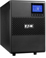
9SX700I
1 Input AC power source
2 Slot for optional communication card
3 Relay output contact
4 Connector for additional battery
module
5 Primary outlets (critical equipment)
6 Group 1: programmable outlets
7 Group 2: programmable outlets
8 Connector for automatic recognition of
an additional battery module
9 RS232 communication port
10 USB communication port
11 RPO port (Remote Power Off)
9SX1000I
9SX1500I
Page 10 614-20306-00 — 9SX 0-6 KVA EMEA_EN
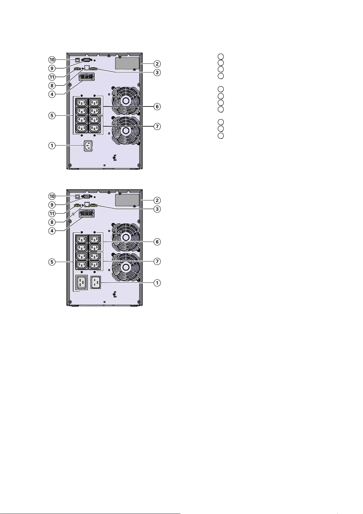
9SX2000I
1 Input AC power source
2 Slot for optional communication card
3 Relay output contact
4 Connector for additional battery
module
5 Primary outlets (critical equipment)
6 Group 1: programmable outlets
7 Group 2: programmable outlets
8 Connector for automatic recognition of
an additional battery module
9 RS232 communication port
10 USB communication port
11 RPO port (Remote Power Off)
9SX3000I
2. Presentation

Page 11
614-20306-00 — 9SX 0-6 KVA EMEA_EN
9SX5KI — 9SX6KI
1 Input AC power source
1a Bypass connection
1b Input AC power source
1c Output
2 Slot for optional communication card
3 Relay output contact
4 Connector for additional battery
module
5 Primary outlets (critical equipment)
6 Group 1: programmable outlets
7 Group 2: programmable outlets
8 Connector for automatic recognition of
an additional battery module
9 RS232 communication port
10 USB communication port
11 RPO port (Remote Power Off)
9SX1000IR
9SX1500IR
2. Presentation
Page 12 614-20306-00 — 9SX 0-6 KVA EMEA_EN
2. Presentation
9SX2000IR
1 Input AC power source
2 Slot for optional communication card
3 Relay output contact
4 Connector for additional battery
module
5 Primary outlets (critical equipment)
6 Group 1: programmable outlets
7 Group 2: programmable outlets
8 Connector for automatic recognition of
an additional battery module
9 RS232 communication port
10 USB communication port
11 RPO port (Remote Power Off)
9SX3000IR
9SXEBM36T — 9SXEBM48T
12 Connectors for battery modules
(to the UPS or to the other battery
modules)
13 Connectors for automatic recognition
of battery modules
9SXEBM96T
Page 13
614-20306-00 — 9SX 0-6 KVA EMEA_EN
2. Presentation
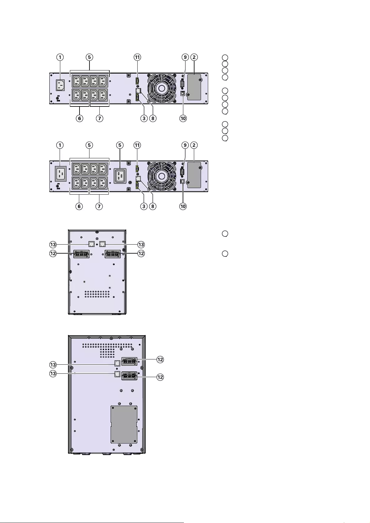
9SXEBM240T
12 Connectors for battery modules
(to the UPS or to the other battery
modules)
13 Connectors for automatic recognition
of battery modules
9SXEBM36R — 9SXEBM48R — 9SXEBM72R
2.3 Accessories
Part number Description
Network-MS /
Network M2 Network card
Modbus-MS Modbus and network card
INDGW-M2 Industrial Gateway Card MiniSlot
Relay-MS Relay card
EBMCBL36T
EBMCBL48T
EBMCBL96T
EBMCBL240T
Eaton 2 m cable 36V EBM Tower
Eaton 2 m cable 48V EBM Tower
Eaton 2 m cable 96V EBM Tower
Eaton 2 m cable 240V EBM Tower
9SXIK1KI
9SXIK3KI
Eaton 9SX1000I Marine Installation kit
Eaton 9SX3000I Marine Installation kit
9SXMF3KI Eaton 9SXMarine filter

Page 14 614-20306-00 — 9SX 0-6 KVA EMEA_EN
3.1 Inspecting the equipment
If any equipment has been damaged during shipment, keep the shipping cartons and packing materials for
the carrier or place of purchase and fi le a claim for shipping damage. If you discover damage after acceptance,
fi le a claim for concealed damage.
To fi le a claim for shipping damage or concealed damage:
1. File with the carrier within 15 days of receipt of the equipment;
2. Send a copy of the damage claim within 15 days to your service representative.
Check the battery recharge date on the shipping carton label. If the date has passed and the batteries were
never recharged, do not use the UPS. Contact your service representative.
3.2 UPS Tower 0-3KVA
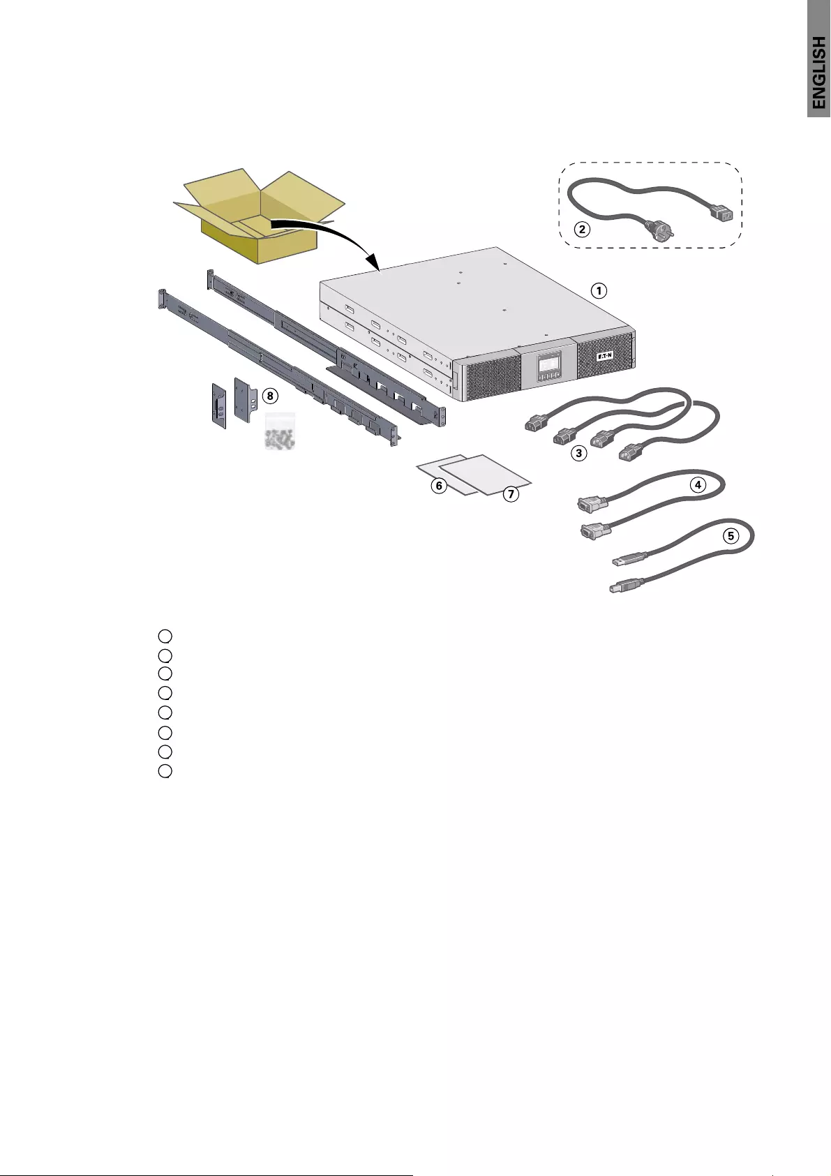
A — Checking the accessory kit
• Verify that the following additional items are included with the UPS:
1 9SX UPS
2 Connection cable to AC-power source (3KVA models only)
3 2 connection cables for the protected equipment
4 RS232 communication cable
5 USB communication cable
6 Safety instructions
7 Quick start
B — Installation
If you ordered other UPS accessories, refer to specifi c user manuals to check the tower installation with the
UPS.
1. Place the UPS on a fl at, stable surface in its fi nal location.
2. Always keep 150 mm of free space behind the UPS rear panel.
3. Installation

Page 15
614-20306-00 — 9SX 0-6 KVA EMEA_EN
C — UPS connection
Check that the indications on the name plate located on the back of the UPS meets to the AC-power source
and the true electrical consumption of the total load.
1. 9SX700I / 1000I / 1500I / 2000I: connect the UPS input socket
1 to the AC-power source using the cable of the protected
equipment.
9SX3000I: connect the supplied cable 15 (250 V — 16 A) to the
socket 1, then to the AC-power source.
2. Connect the loads to the UPS using the cables 16 .
It is preferable to connect the priority loads to the outlets
marked 5 and the non-priority loads to the outlets marked
6 7 that can be programmed (see 2.2 «Rear panels»).
Connect any high-power devices to the 16 A outlet.
To program shutdown of outlets 6 7 during operation on
battery power and thus optimise the available backup time,
please check the in/out settings.
Note: The UPS charges the battery as soon as it is connected to the AC-power source, even if button is not
pressed.
Once the UPS is connected to the AC-power source, 24 hours of charging are required before the battery can
supply the rated backup time.
3.3 EBM Tower 0-3KVA
A — Checking the accessory EBM
1 9SX EBM
2 Battery power cable, attached with battery detection cable
3 Quick start
4 EBM Installation manual.
Discard the EBM user’s guide if you are installing the EBM with a new UPS at the same time.
Use the UPS user’s guide to install both the UPS and the EBM.
If you ordered other UPS accessories, refer to specifi c user manuals to check the packing contents.
3. Installation

Page 16 614-20306-00 — 9SX 0-6 KVA EMEA_EN
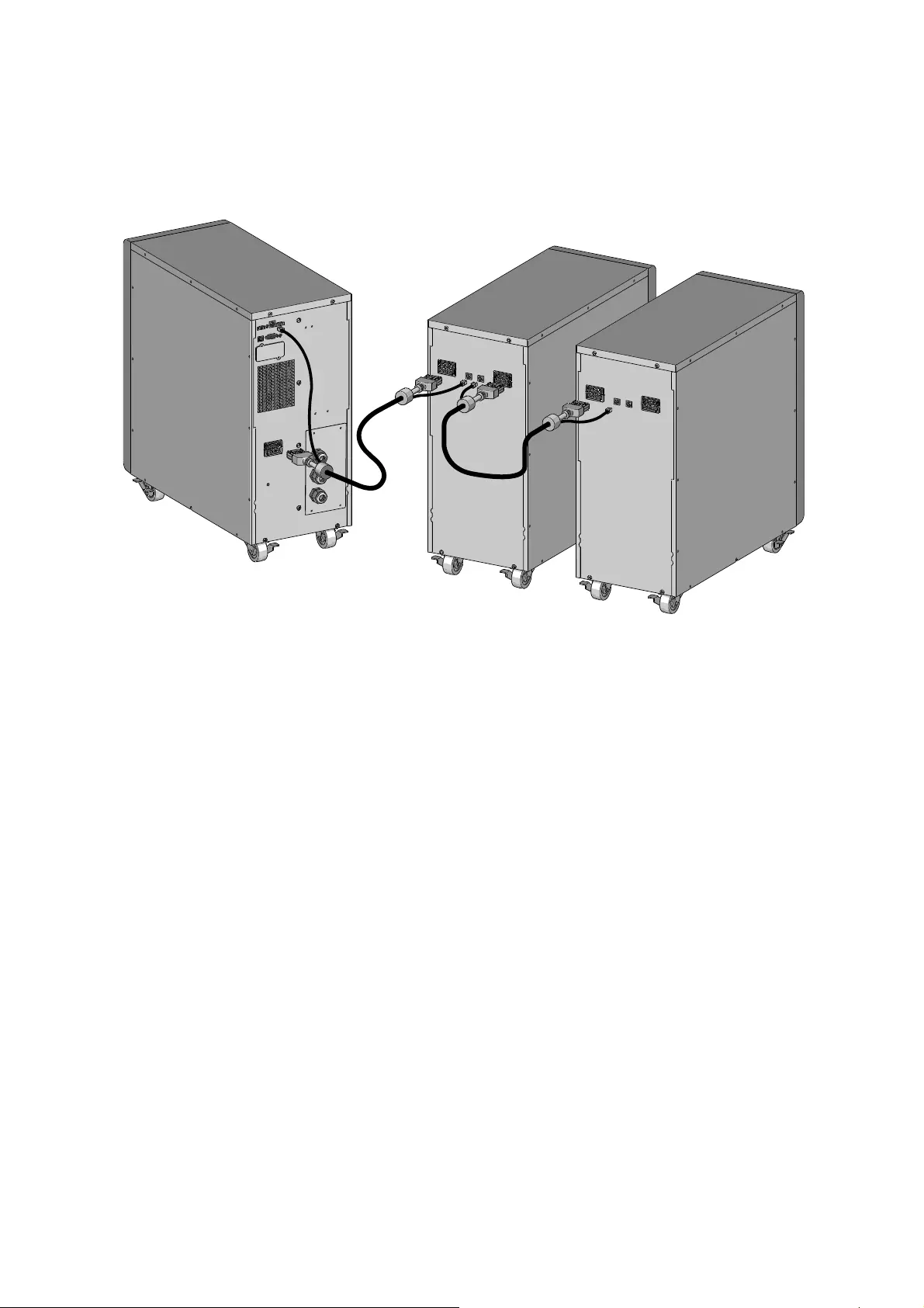
B — Connecting the EBM
1. Plug the EBM power cable(s) into the battery connector(s). Up to 4 EBMs may be connected to the UPS.
2. Verify that the EBM connections are tight and that adequate bend radius and strain relief exist for each
cable.
3. Connect the battery detection cable(s) to the connector of the UPS and of the EBM(s).
3.4 UPS Tower 5-6KVA
A — Checking the accessory kit
• Verify that the following additional items are included with the UPS:
1 9SX UPS
2 2 stabilizing feet
3 RS232 communication cable
4 USB communication cable
5 Safety instructions
6 Quick start
3. Installation

Page 17
614-20306-00 — 9SX 0-6 KVA EMEA_EN
3. Installation
B — Unpacking:
Follow from step 1 to 6 to unpack the UPS:
C — Installation:
To install the cabinet:
1. Place the UPS on a fl at, stable surface in its fi nal location.
2. Always keep 150 mm of free space behind the UPS rear panel.
3. If installing additional cabinets, place them next to the UPS in their fi nal location.

Page 18 614-20306-00 — 9SX 0-6 KVA EMEA_EN
3. Installation
D — UPS connection
Check that the indications on the name plate located on the back of the UPS meets the AC-power source
and the true electrical consumption of the total load. The output cable must not exceed 10 m.
E — Installation requirements
Required protective devices and cable cross-sections
1. Recommended upstream protection
Table 1. Upstream circuit breaker rating
UPS power rating Upstream circuit breaker
5KVA / 6KVA D curve – 40 A
2. Required cable cross-sections
Table 2. Cable cross sections
UPS power rating
5KVA / 6KVA
Minimum of section
required
Terminal-block capacity
Phase and neutral solid or
stranded wire
6 mm²
AWG 10
10 mm²
AWG 8
Earthing solid or stranded
wire
6 mm²
AWG 10
10 mm²
AWG 8
F — Installation depending on the system earthing arrangement (SEA)
UPS with common Normal and Bypass inputs
Change in SEA between upstream and downstream or galvanic isolation required
2 poles circuit breaker
To UPS input source
and/or Bypass source.
Main low
voltage
switchboard
(MLVS)
Bypass
Input
Load
Output
Main low
voltage
switchboard
(MLVS)
Bypass
Input
Load
Output

Page 19
614-20306-00 — 9SX 0-6 KVA EMEA_EN
3. Installation
UPS with separate Normal and Bypass inputs
Change in SEA between upstream and downstream or galvanic isolation required
The transformer is not necessary if:
• Normal and Bypass inputs are connected to the same source,
• and wires cross sections and wires lengths on Input and Bypass inputs are identical,
• and upstream protection is provided by only one switch with RCD (residual current
device) for Input and Bypass inputs.
UPS with separate Input and Bypass inputs, supplied by separate sources
Change in SEA between upstream and downstream or galvanic isolation required
Frequency converter (without Bypass input)
Confi guration used when the frequency of the application differs from the Mains, example: marine
requirements.
Main low
voltage
switchboard
(MLVS)
Bypass
Input
Load
Output
Main low
voltage
switchboard
(MLVS)
Bypass
Input
Load
Output
Bypass
Bypass
Input
Input
Load
Load
MLVS1
MLVS1
MLVS2
MLVS2
Output
Output
Bypass
Input
Load
MLVS1
MLVS2
Output
Main low
voltage
switchboard
(MLVS)
Input
Load
Output

Page 20 614-20306-00 — 9SX 0-6 KVA EMEA_EN
3. Installation
G — Access to terminal block and cable wiring
1. Access to terminal block: remove the 4 screws of the terminal block cover.
2. Follow instructions in below sections to wire and secure the cables depending on your connection.
• High leakage current:
Earth connection essential before connecting supply.
H — Common input sources connection
This type of connection must be carried out by qualified electrical personnel.
Before carrying out any connection, check that the upstream protection device Input source is open («O»)
(OFF).
Always connect the earthing wire first.
1. Make sure the metal jumper is connected.
2. Insert the Input source cable through the cable.
3. Connect the 3 cables to the Input source terminal block.
4. Insert the Output cable through the cable gland.
5. Connect the 3 cables to the output terminal block
(10 lb in / 1.2 Nm).
6. Put back and secure the terminal block cover with the 4
screws.
7. Tightened the cable glands.

Page 21
614-20306-00 — 9SX 0-6 KVA EMEA_EN
3. Installation
I — Separate input sources connection
This type of connection must be carried out by qualified electrical personnel.
Before carrying out any connection, check that the upstream protection device Input source is open («O»)
(OFF).
Always connect the earthing wire first.
1. Remove the metal jumper.
2. Insert the Input source cable through the cable gland.
3. Connect the 3 cables to the Input terminal block.
4. Insert the Bypass source cable through the cable gland.
5. Connect the 3 cables to the Bypass terminal block.
6. Insert the Output cable through the cable gland.
7. Connect the 3 cables to the output terminal block
(10 lb in / 1.2 Nm).
8. Put back and secure the terminal block cover with the 4
screws.
9. Tightened the cable glands.
J — Frequency converter connection
This type of connection must be carried out by qualified electrical personnel.
Before carrying out any connection, check that the upstream protection device Input source is open («O»)
(OFF).
Always connect the earthing wire first.
1. Remove the metal jumper.
2. Insert the Input source cable through the cable gland.
Do not connect anything to the Bypass terminal
block.
3. Connect the 3 cables to the Input terminal block.
4. Insert the Output cable through the cable gland.
5. Connect the 3 cables to the output terminal block
(10 lb in / 1.2 Nm).
6. Put back and secure the terminal block cover with the 4
screws.
7. Tightened the cable glands.
Note: The UPS charges the battery as soon as it is connected to the AC-power source, even if button is not
pressed.
Once the UPS is connected to the AC-power source, 24 hours of charging are required before the battery can
supply the rated backup time.

Page 22 614-20306-00 — 9SX 0-6 KVA EMEA_EN
3. Installation
3.5 EBM Tower 5-6KVA
A — Checking the accessory EBM
1 9SX EBM
2 Battery power cable, attached with battery detection cable
3 Quick start
4 EBM Installation manual
Discard the EBM user’s guide if you are installing the EBM with a new UPS at the same time.
Use the UPS user’s guide to install both the UPS and the EBM.
If you ordered other UPS accessories, refer to specifi c user manuals to check the packing contents.

Page 23
614-20306-00 — 9SX 0-6 KVA EMEA_EN
3. Installation
B — Unpacking:
Follow from step 1 to 6 to unpack the EBM:
C — Installation:
To install the cabinet:
1. Place the EBM on a fl at, stable surface in its fi nal location.
2. Always keep 150 mm of free space behind the EBM rear panel.
3. If installing additional cabinets, place them next to the EBM in their fi nal location.
Page 24 614-20306-00 — 9SX 0-6 KVA EMEA_EN
3. Installation
D — Connecting the EBM
1. Plug the EBM power cable(s) into the battery connector(s). Up to 4 EBMs may be connected to the UPS.
2. Verify that the EBM connections are tight and that adequate bend radius and strain relief exist for each
cable.
3. Connect the battery detection cable(s) to the connector of the UPS and of the EBM(s).
Page 25
614-20306-00 — 9SX 0-6 KVA EMEA_EN
3. Installation
3.6 UPS Rack 0-3KVA
A — Checking the accessory kit
• Verify that the following additional items are included with the UPS:
1 9SX UPS
2 Connection cable to AC-power source (3KVA models only)
3 2 connection cables for the protected equipment
4 RS232 communication cable
5 USB communication cable
6 Safety instructions
7 Quick start
8 Mounting kit for 19-inch enclosures

Page 26 614-20306-00 — 9SX 0-6 KVA EMEA_EN
3. Installation
B — Installation
• Rack mounting of UPS and accessory modules.
Follow steps 1 to 4 for module mounting on the rails.
C — UPS connection
Check that the indications on the name plate located on the back of the UPS meets to the AC-power source
and the true electrical consumption of the total load.
1. 9SX1000IR / 1500IR / 2000IR: connect the
UPS input socket 1 to the AC-power
source using the cable of the protected
equipment.
9SX3000IR: connect the supplied cable
15 (250 V — 16 A) to the socket 1, then to
the AC-power source.
2. Connect the loads to the UPS using the
cables 16 .
It is preferable to connect the priority
loads to the outlets marked 5 and the
non-priority loads to the outlets marked
6 7 that can be programmed (see 2.2
«Rear panels»).
For the 9SX3000IR model, connect any
high-power devices to the 16 A outlet.
To program shutdown of outlets 6 7
during operation on battery power and
thus optimise the available backup time,
please check the in/out settings.
Note: The UPS charges the battery as soon as it is connected to the AC-power source, even if button is not
pressed.
Once the UPS is connected to the AC-power source, 24 hours of charging are required before the battery can
supply the rated backup time.

Page 27
614-20306-00 — 9SX 0-6 KVA EMEA_EN
3. Installation
3.7 EBM Rack 0-3KVA
A — Checking the accessory kit
• If you ordered an optional Extended Battery Module (EBM), verify that the following additional items are
included with the EBM:
1 9SX EBM
2 Battery detection cable
3 Quick start
4 EBM Installation manual
5 Rack kit for 19-inch enclosures (optional)
B — Installation
• Rack mounting of EBM, and accessory modules.
Follow steps 1 to 4 for module mounting on the rails.
Page 28 614-20306-00 — 9SX 0-6 KVA EMEA_EN
3. Installation
C — Connecting the EBM
A small amount of arcing may occur when connecting an EBM to the UPS. This is normal and will not harm
personnel. Insert the EBM cable into the UPS battery connector quickly and fi rmly.
1. Remove the EBM front panel.
2. Plug the EBM power cable(s) into the battery connector(s). Up to 4 EBMs may be connected to the UPS.
Verify that the EBM connections are tight and that adequate bend radius and strain relief exist for each
cable.
3. Put back the EBM front panel.
4. Connect the battery detection cable(s) to the connector of the UPS and of the EBM(s).
3.8 Connecting other accessories
If you ordered other UPS accessories, refer to specifi c user manuals to check the connection to the UPS.
Page 29
614-20306-00 — 9SX 0-6 KVA EMEA_EN
4. Interfaces and Communication
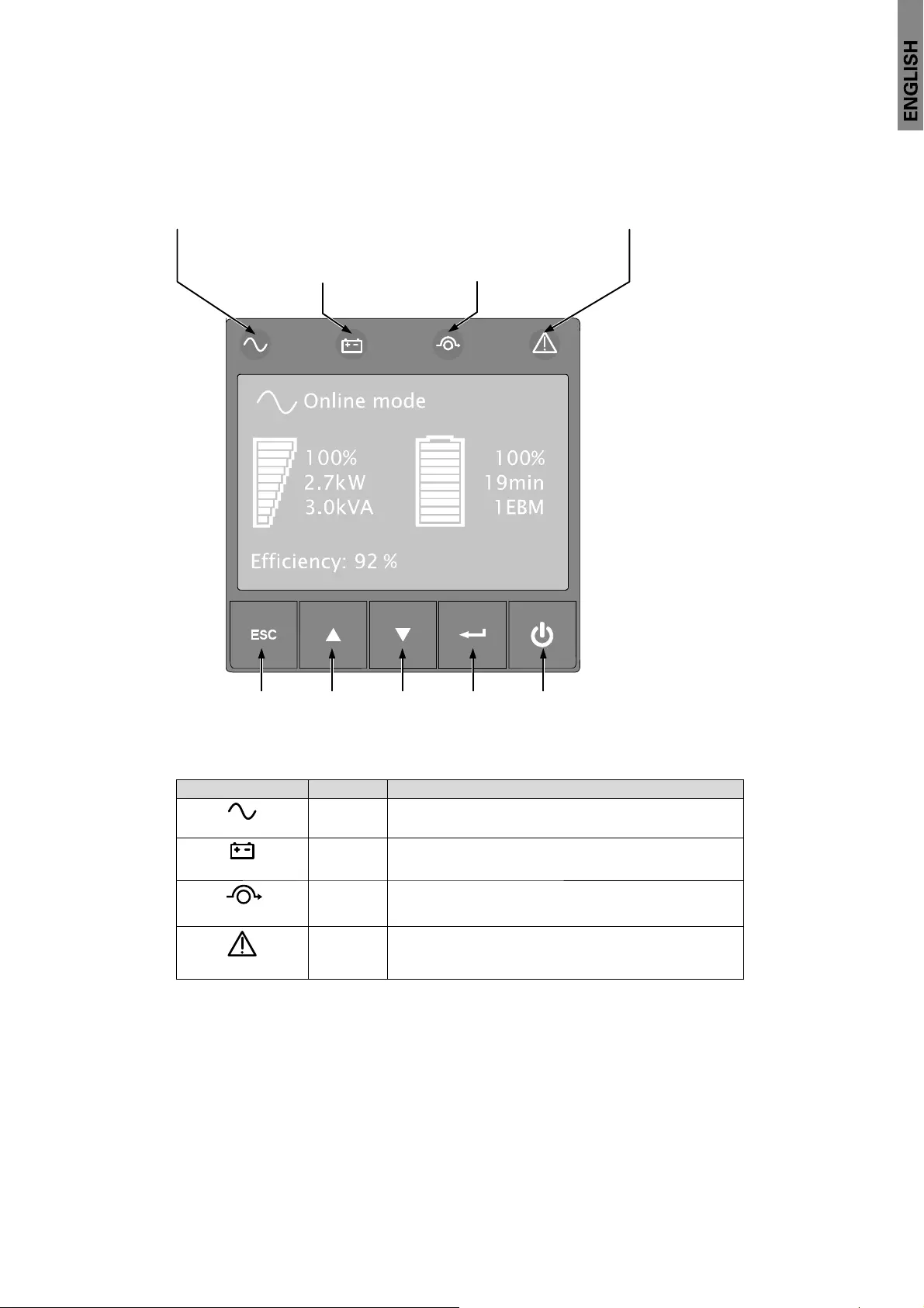
4.1 Control panel
The UPS has a fi ve-button graphical LCD. It provides useful information about the UPS itself, load status,
events, measurements and settings.
Online mode
indicator (green)
Fault
indicator (red)
Escape Up Down Enter On/Off
button
Battery mode
indicator (orange)
Bypass mode
indicator (orange)
The following table shows the indicator status and description:
Indicator Status Description
Green On The UPS is operating normally on Online or on High
Efficiency mode.
Orange On The UPS is on Battery mode.
Orange On The UPS is on Bypass mode.
Red
On
The UPS has an active alarm or fault. See
troubleshooting on page 50 for additional
information.

Page 30 614-20306-00 — 9SX 0-6 KVA EMEA_EN
4. Interfaces and Communication
4.2 LCD description
After 5 minutes of inactivity, the LCD displays the screen saver.
The LCD backlight automatically dims after 10 minutes of inactivity. Press any button to restore the screen.
Operation status
Load/equipment status Battery status
Efficiency and load group information
The following table describes the status information provided by the UPS.
Note: If other indicator appears, see troubleshooting on page 50 for additional information.
Operation status Cause Description
Standby mode The UPS is Off, waiting form start-up
command from user. Equipment is not powered until
button is pressed.
Online mode The UPS is operating normally. The UPS is powering and protecting
the equipment.
Battery mode
1 beep every 10 seconds
A utility failure has occurred and the
UPS is on Battery mode.
The UPS is powering the equipment
with the battery power.
Prepare your equipment for
shutdown.
End of backup time
1 beep every 3 seconds
The UPS is on Battery mode and the
battery is running low.
This warning is approximate, and
the actual time to shutdown may
vary significantly.
High Efficiency mode The UPS is operating on High
Efficiency mode.
The UPS is powering and protecting
the equipment.
Bypass mode An overload or a fault has occurred,
or a command has been received,
and the UPS is on Bypass mode.
Equipment is powered but not
protected by the UPS.

Page 31
614-20306-00 — 9SX 0-6 KVA EMEA_EN
4. Interfaces and Communication
4.3 Display functions
Press the Enter ( ) button to activate the menu options. Use the two middle buttons ( and ) to scroll
through the menu structure. Press the Enter ( ) button to select an option. Press the button to cancel or
return to the previous menu.
Main menu Submenu Display information or Menu function
Measurements [Load] W VA A pf / [Input/Output] V Hz / [Efficiency] % /
[Battery] % min V n° [Battery remaining life] months /
[Average power usage] Wh / [Cumulated power] Wh
Control Go to Bypass Transfers the UPS on Bypass mode
Load segments On/Off Commands the load segments
Start battery test Starts a manual battery test
Connectivity test Tests dry contact relay outputs and relay card contacts.
Simulates line failure and battery low
Function reset Clears active fault, power usage, battery remaining life, reset
NMC, Restore factory settings
Settings Local settings Sets product general parameters
In/Out settings Sets Input and Output parameters
On/Off settings Sets On/Off conditions
Battery settings Sets battery configuration
Com settings Sets communication parameters
Event log Event filter Selects faults, alarms and/or events to display
Event list Displays the events stored
Reset event list Clears events
Fault log Fault list Displays the faults stored
Reset fault list Clears faults
Identification [Product type/model] / [Part/Serial number] / [UPS/NMC
firmware] / [Com card IPv4], [Com card IPv6], [Com card MAC]
Registration Links to Eaton registration website
4.4 User settings
The following table displays the options that can be changed by the user.
Submenu Available settings Default settings
Local settings
Language [English] [Français] [Español]
[Português] [Simplified Chinese]
[Italiano] [Deutsch] [Русский] [Japanese]
Menus, status, notices and alarms, UPS
fault, Event Log data and settings are in
all supported languages.
[English]
User selectable when UPS is
powered for the first time.
Date / time Format:
[International] [US]
[International]
LCD Modify LCD screen brightness and
contrast to be adapted to room light
conditions.
Audible alarm [Enabled] [Disabled on battery] [Always
disabled]
Enable or disable the buzzer if an alarm
occurs.
[Enabled]
Level: [High] [Low] [High]
Protected access [Enabled] [Disabled]
Password is: 0577
[Disabled]

Page 32 614-20306-00 — 9SX 0-6 KVA EMEA_EN
4. Interfaces and Communication
Submenu Available settings Default settings
In/Out settings
Output voltage [200V] [208V] [220V] [230V] [240V] [230V]
Output frequency Mode: [Normal] [Converter] [Marine]
Frequency can be changed in Frequency
[Converter] mode
In [Marine] mode output frequency
follows input frequency
[Normal]
Output mode Mode: [Industrial] [IT] [Custom]
Overload: [Inv>Stop] [Inv>BP]
[Inv>BP>Inv]
Short—circuit: [Inv>Stop] [Inv>BP]
[Inv>BP>Inv]
[IT]
[Inv>BP>Inv]
[Inv>Stop]
Input volt hysteresis Sets input voltage hysteresis
from [1] to |10V]
[10V]
High Efficiency
mode
[Enabled] [Disabled]
Power the output from Bypass for high
efficiency
[Disabled]
Bypass settings [Volt low]
[Volt high]
[Qualify]
[Hz synch]
[Unsynch]
[160V];
[276V];
[In spec];
[5%];
[Half cycle]
Load segments [Auto start delay]
[Auto shutdown delay]
UPS: [0s]; Group1: [3s];
Group2: [6s]
UPS: [Disabled]; Group1:
[Disabled]; Group2:
[Disabled]
Overload
prealarm
[10%] … [102%]
Load % when overload alarm occurs
[102%]
On/Off settings
Start/Restart [Cold start] [Auto restart] [Auto start]
[Start on bypass]
[Cold start] [Auto restart] are
Enabled
[Auto start] [Start on bypass]
are Disabled
Forced reboot [Enabled] [Disabled]
[Timer] [10s] … [180s]
When mains recover during a shutdown
sequence:
If set to Enabled, shutdown sequence
will complete and wait 10 seconds prior
to restart,
If set to Disabled, shutdown sequence
will not complete, UPS stays on.
[Enabled]
[10s]
Energy saving [Enabled] [Disabled]
[Time] [1min] … [15min]
[Level] [100W] … [1000W]
If Enabled, UPS will shut-down after
defined duration. of back-up time, if
load is less than set value.
[Disabled]
[5min]
[100W]
Sleep mode [Enabled] [Disabled]
[Timer] [10min] … [120min]
If Disabled, LCD and communication
will turn OFF immediately after UPS
is OFF.
If Enabled, LCD and communication
stays ON 1h30 min after UPS is OFF.
[Enabled]
[90min]
Site wiring fault [Enabled] [Disabled]
Prevents from starting the UPS in case
of phase vs neutral wires swapping.
[Disabled]
Power Off alert [Enabled] [Disabled]
If Enabled, activates a confirmation
screen that requires user confirmation
after pressing the power button, before
the UPS shutdown occurs.
[Enabled]

Page 33
614-20306-00 — 9SX 0-6 KVA EMEA_EN
Submenu Available settings Default settings
Battery settings
Automatic battery
test
In ABM® cycling mode:
[No test] [Every ABM® cycle]
In constant charge mode:
[No test] [Every day] [Every week]
[Every month]
[Every ABM® cycle]
[Every week]
Low battery
warning
[Capacity] [0%] … [100%]
[Runtime] [0min] … [60min]
The alarm triggers when the set
percentage of battery capacity or
remaining back-up time is reached.
[0%]
[3min]
Restart bat. level [0%] … [100%]
If set, automatic restart will occur only
when percentage of battery charge is
reached.
[0%]
Battery charge
mode
[ABM® cycling] [Constant charge] [ABM® cycling]
External battery [Auto detection] [Manual EBM set.]
[Manual battery set.]
[Auto detection]
Using standard EBM, UPS
detects automatically the
number of EBM connected
Deep Disch.
protect.
[Yes] [No]
If set to Yes, the UPS automatically
prevents battery from deep discharge
by adapting end of back-up time voltage
threshold.
Warranty void if set to No.
[Yes]
Com settings
Input signals [RPO] [DB9-4]
Sets Input signals parameters (function,
delay, operation) through external
contact connectors or RS232 port.
RPO port:
— [Function]: [No] [ROO] [RPO]
[Building alarm] [Forced bypass] [On
generator] [Remote shutdown]
— [Delay]: [0s] … [999s]
— [Active]: [Open] [Closed]
DB9-4 port:
— [Function]: [No] [ROO] [RPO]
[Building alarm] [Forced bypass] [On
generator] [Remote shutdown]
— [Delay]: [0s] … [999s]
— [Active]: [High] [Low]:
[No]
[0s]
[Open]
[No]
[0s]
[High]
4. Interfaces and Communication

Page 34 614-20306-00 — 9SX 0-6 KVA EMEA_EN
4. Interfaces and Communication
Submenu Available settings Default settings
Com settings
Output signals [Relay] [DB9-1] [DB9-8]
Sets events or fault that will actuate
Output signal parameters through
external contact connector or RS232
port
[Relay]: [On bat] [Low bat] [Bat fault]
[Bypass] [UPS OK] [Load protected]
[Load powered] [General alarm] [Ext.
charger ON] [OVL pre-alarm]
[DB9-1]: [On bat] [Low bat] [Bat fault]
[Bypass] [UPS OK] [Load protected]
[Load powered] [General alarm] [Ext.
charger ON] [OVL pre-alarm]
[DB9-8]: [On bat] [Low bat] [Bat fault]
[Bypass] [UPS OK] [Load protected]
[Load powered] [General alarm] [Ext.
charger ON] [OVL pre-alarm]
[Relay] [Bypass]
[DB9-1] [Low bat]
[DB9-8] [On bat]
Remote command [Enabled] [Disabled]
If Enabled, shutdown or restart
commands from software are
authorized.
[Enabled]
Shutdown
commands
[Send CMD] [Output OFF] [OFF delay]
[restart]
Sets events or fault that will actuate
Output signal parameters through
external contact connector or RS232
port
[Send CMD]: [Yes] [No]
[Output OFF]: [No] [UPS] [Group 1]
[Group 2] [Group 1 + Group 2]
[OFF delay]: [0s] …[999s]
[Restart]: [Yes] [No]
For a proper server shutdown please
make sure that the Output OFF delay is
long enough
Send CMD: [No]
Output OFF: [No]
OFF delay: [0s]
Restart: [Yes]
On battery notice
delay
[0s] ... [99s]
Sets delay before noticing on battery
information to software.
[0s]
General alarm [On battery] [Battery fault] [Overload
pre-alarm] [Internal fault] [Ambient
temp.] [Fan lock] [Bypass overload]
[Current limit] [Short circuit] [Inverter
overload] [Power overload] [Low
battery] [On bypass] [UPS OK] [Load
protected] [Load powered] [Ext. charger
ON]
Defines which event or fault generate
a general alarm through Output signal
screen.
[Internal fault]

Page 35
614-20306-00 — 9SX 0-6 KVA EMEA_EN
4. Interfaces and Communication
4.5 Communication ports
Connection of RS232 or USB communication port
Independent Multiplexed
Communication Bay USB RS-232
Any connectivity card Available Not in use
Any connectivity card Not in use Available
1. Connect the RS232 17 or USB 18 communication cable to the serial or USB port on the computer
equipment.
2. Connect the other end of the communication cable 17 or 18 to the USB 10 or RS232 9 communication
port on the UPS.
The UPS can now communicate with EATON power management software.
Installation of the communication cards (optional)
It is not necessary to shutdown the UPS
before installing a communication card.
1. Remove the slot cover 2 secured by
screws.
2. Insert the communication card in the
slot.
3. Secure the card cover with the 2 screws.
Characteristics of the contact RS232 communication port
Contact characteristics (optocoupler)
• Voltage: 48 V DC max
• Current: 25 mA max
Pin Signal Direction Function
1 Bat Low Output Low Battery Output
2 TxD Output Transmit to external device
3 RxD Input Receive from external device
4 I/P SIG Input —
5GNDS — Signal Common tied to
chassis
6 PNP Input Plug and Play
7
8BAT ModeOutput —
9 +5V Output Power supply for external
signal or options
Page 36 614-20306-00 — 9SX 0-6 KVA EMEA_EN
4.6 UPS remote control functions
Programmable Signal Inputs
The 9SX incorporates 2 programmable signal inputs: one RPO terminal input, one RS-232 input (pin-4). Signal
inputs can be confi gured (see Settings > Com settings > Signal Input on page33) to have one of the following
functions:
Function Description
No No function, please choose a function if you want to use input signal
RPO Remote Power off (RPO) is used to shutdown the UPS remotely
ROO Remote On/Off allows remote action of button to switch On/Off the UPS.
(Cold start is prohibited while using the ROO function)
Forced bypass If feeding the load the unit goes to bypass operation and stays there regardless of the
bypass state until the input is inactivated
Building
alarm
Active input generates an alarm “building alarm”
On generator Active input disables synchronization and transfers to bypass
Remote
shutdown
Active input turns UPS output (or outlet groups) off after a user defi ned shutdown
delay but keeps on charging batteries according to a selected charging scheme,
inactive input does not abort shutdown countdown. Depending on the “Restart”
parameter (see Settings > Com Settings > Shutdown commands on page 34) the unit
may startup automatically.
Warning Signal inputs have no function by default please choose a function through the LCD
(Settings > Com settings > Input signals on page 33).
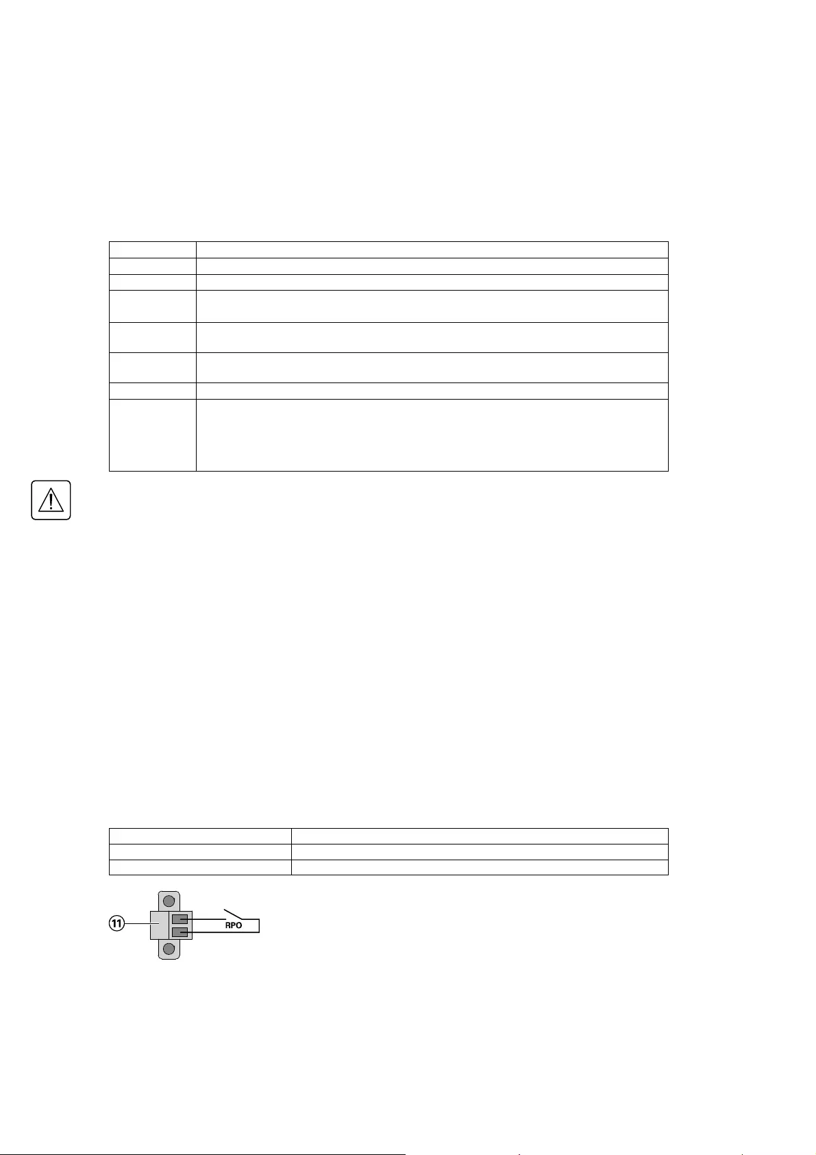
See below example of confi guration with RPO terminal used as RPO function:
• Remote Power Off (RPO)
RPO is used to shutdown the UPS remotely when the contact is open. This feature can be used for shutting
down the load and the UPS by thermal relay, for instance in the event of room over temperature. When RPO
is activated, the UPS shuts down the output and all its power converters immediately. The UPS remains on
to alarm the fault.
The RPO circuit is an IEC 60950 safety extra low voltage (SELV) circuit. This circuit must be separated from any
hazardous voltage circuits by reinforced insulation.
• The RPO must not be connected to any utility connected circuits. Reinforced insulation to the utility is
required. The RPO switch must be a dedicated latching-type switch not tied into any other circuit. The RPO
signal must remain active for at least 250 ms for proper operation.
• To ensure the UPS stops supplying power to the load during any mode of operation, the input power must
be disconnected from the UPS when the Remote Power Off function is activated.
Leave the RPO connector installed in the RPO port on the UPS even if the RPO function is not needed.
RPO connections:
RPO Comments
Connector type Terminal, 14 AWG Maximum wires
External breaker specifi cation 60 V DC/30 V AC 20 mA max
4. Interfaces and Communication

Page 37
614-20306-00 — 9SX 0-6 KVA EMEA_EN
4. Interfaces and Communication
• Remote control connection and test
1. Check the UPS is shut down and the electrical supply network disconnected.
2. Remove RPO connector from the UPS by unfi tting the screws.
3. Connect a normally closed volt-free contact between the two pins of connector.
Contact open: shut down of UPS.
To return to normal operation, deactivate the external remote shut down contact
and restart the UPS from the front panel.
Normally closed
4. Plug the RPO connector into the back of the UPS and fi x the screws.
5. Connect and restart the UPS according to the previously described procedures.
6. Activate the external remote shut down contact to test the function.
Always test the RPO function before applying your critical load to avoid accidental load loss.
Programmable Signal Outputs
The 9SX incorporates 3 programmable signal outputs: one relay output, 2 optocouplers outputs (pin-1/8).
Signal outputs can be confi gured (see Settings > Com settings > Output Signals on page 34) to report the
following information:
Signal Default
assignment
Description
On battery (On bat) DB9-Pin 8 UPS is in battery mode
Low battery (Low bat) DB9-Pin 1 Battery is nearly empty
Battery fault (Bat fault) — Battery fault
Bypass Relay output (1) UPS is operating in Bypass mode
Load powered — Load is powered (from inverter or bypass)
Load protected — UPS is on inverter, with no alarm and ready to go to battery
General alarm — Choose events that will trigger this alarm trough the
LCD (Settings > Com settings > General alarm) for more
information on possible events please look at page 34.
Ext charger ON — Control an optional external battery charger on and off.
OVL pre-alarm — Overload pre-alarm
(1) Relay output:

Page 38 614-20306-00 — 9SX 0-6 KVA EMEA_EN
4. Interfaces and Communication
Connectivity Cards
Connectivity cards allow the UPS to communicate in a variety of networking environments and with different
types of devices. The 9SX models have one available communication bay for the following connectivity cards:
• Network-MS card — has SNMP and HTTP capabilities as well as monitoring through a Web browser
interface; connects to Ethernet network. In addition, a Environmental Monitoring Probe can be attached to
obtain humidity, temperature, smoke alarm, and security information.
• Gigabit Network card (NETWORK-M2) — provides a Gigabit Ethernet connection and enables secure UPS
monitoring over HTTPS web browser interface, SNMP v1/v3 protocol and email alarms. In addition, up to
3 Environmental Monitoring Probes can be attached to obtain humidity, temperature, smoke alarm, and
security information.
• Modbus-MS card — has connection to Modbus protocol in addition to network management.
• Relay-MS card — has isolated dry contact (Form-C) relay outputs for UPS status: Utility failure, Battery low,
UPS alarm/OK, or on Bypass.
4.7 Eaton Intelligent Power Software suite
Eaton Intelligent Power Software suite is available from eaton.com/downloads.
Eaton Software suite provides up-to-date graphics of UPS power and system data and power fl ow.
It also gives you a complete record of critical power events, and it notifi es you of important UPS or power
information.
If there is a power outage and the 9SX UPS battery power becomes low, Eaton Software suite can automatically
shut down your computer system to protect your data before the UPS shutdown occurs.
4.8 Cybersecurity
Eaton is committed to minimizing the Cybersecurity risk in its products and deploys cybersecurity best
practices and latest cybersecurity technologies in its products and solutions, making them more secure,
reliable and competitive for our customers. Eaton also offers Cybersecurity Best Practices whitepapers to its
customers, referenced at www.eaton.com/cybersecurity.

Page 39
614-20306-00 — 9SX 0-6 KVA EMEA_EN
5. Operation
5.1 Start-up and Normal operation
To start the UPS:
1. Verify that the UPS power cord is plugged in.
2. The UPS front panel display illuminates and shows EATON logo.
3. Verify that the UPS status screen shows .
4. Press the button on the UPS front panel for at least 2 seconds.
The UPS front panel display changes status to «UPS starting…».
5. Check the UPS front panel display for active alarms or notices. Resolve any active alarms before continuing.
See «Troubleshooting» on page 50.
If the indicator is on, do not proceed until all alarms are clear. Check the UPS status from the front panel
to view the active alarms. Correct the alarms and restart if necessary.
6. Verify that the indicator illuminates solid, indicating that the UPS is operating normally and any loads
are powered and protected.
The UPS should be in Normal mode.
5.2 Starting the UPS on Battery
Before using this feature, the UPS must have been powered by utility power with output enabled at least
once. Battery start can be disabled. See the «Cold start» setting in «ON/OFF Settings» on page 32.
To start the UPS on battery:
1. Press the button on the UPS front panel until the UPS front panel display illuminates and shows
a status of «UPS starting…».
The UPS transfers from Standby mode to Battery mode. The indicator illuminates solid.
The UPS supplies power to your equipment.
2. Check the UPS front panel display for active alarms or notices besides the «Battery mode» notice
and notices that indicate missing utility power. Resolve any active alarms before continuing.
See «Troubleshooting» on page 50.
Check the UPS status from the front panel to view the active alarms. Correct the alarms and restart
if necessary.
5.3 UPS Shutdown
To shut down the UPS:
1. Press the button on the front panel for 3 seconds.
A confi rmation message will appear.
When confi rmed, the UPS starts to beep and shows a status of «UPS shutting OFF…». The UPS then
transfers to Standby mode, and the indicator turns off.
5.4 Operating modes
The Eaton 9SX front panel indicates the UPS status through the UPS indicators, see page 29.
Online mode
During Online mode, the indicator illuminates solid and the UPS is powered from the utility.
The UPS monitors and charges the batteries as needed and provides fi ltered power protection to your
equipment. Optional High Effi ciency and Energy Saving settings minimize heat contribution to the rack
environment. See user settings on page 31.
Battery mode
When the UPS is operating during a power outage, the alarm beeps once every 10 seconds and the
indicator illuminates solid. The necessary energy is provided by the battery.
When the utility power returns, the UPS transfers to Online mode operation while the battery recharges.
If battery capacity becomes low while on Battery mode, the audible alarm beeps once every 3 seconds.
This warning is approximate, and the actual time to shutdown may vary signifi cantly.
Shutdown all applications on the connected equipment because automatic UPS shutdown is imminent.
When utility power is restored after the UPS shuts down, the UPS automatically restarts.

Page 40 614-20306-00 — 9SX 0-6 KVA EMEA_EN
5. Operation
Low-battery warning
• The indicator illuminates solid.
• The audio alarm beeps every three seconds.
The remaining battery power is low. Shut down all applications on the connected equipment because
automatic UPS shutdown is imminent.
End of battery backup time
• LCD displays «End of backup time».
• All the LEDs go OFF.
• The audio alarms stops.
Bypass mode
In the event of a UPS overload or internal failure, the UPS transfers your equipment to utility power. Battery
mode is not available and your equipment is not protected; however, the utility power continues to be
passively fi ltered by the UPS. The indicator illuminates.
Depending on overload conditions, the UPS remains in Bypass mode for at least 5 seconds and will stay in
this mode if three transfers to Bypass occur within 20 minutes.
The UPS transfers to Bypass mode when:
• the user activates Bypass mode through the front panel,
• the UPS detects an internal failure,
• the UPS has an overtemperature condition,
• the UPS has an overload condition listed in table 6 on page 54.
The UPS shuts down after a specifi ed delay for overload conditions listed in table 6 on page 54.
The UPS remains on to alarm the fault.
5.5 Return of AC Input Power
Following an outage, the UPS restarts automatically when AC input power returns (unless the restart function
has been disabled) and the load is supplied again.
5.6 Setting High Effi ciency mode
In High Effi ciency mode, the UPS operates normally on Bypass and transfers to Online (or Battery) mode in
less than 10 ms when utility fails. Transfers to High Effi ciency mode will be active after 5 minutes of Bypass
voltage monitoring: if Bypass quality is not in tolerance, then the UPS will remain in Online mode.
Eaton recommends to use the HE mode only to protect IT equipment.
To se t t h e H i g h Ef fi ciency mode:
1. Select Settings, In/Out settings, and High Effi ciency mode.
2. Select Enabled and Enter to confi rm.
3. The UPS transfers to High Effi ciency mode after 5 minutes.
5.7 Confi guring Bypass settings
The following settings are available for confi guring Bypass operation.
Bypass Voltage Low Limit
The default disables a transfer to Bypass if the measured bypass voltage level is below the nominal output
voltage minus 20%. You can confi gure the setting for another voltage value. This setting can be overruled by
the “Qualify Bypass” setting.
Bypass Voltage High Limit
The default disables a transfer to Bypass if the measured bypass voltage level is above the nominal output
voltage plus 15%. You can confi gure the setting for another voltage value. This setting can be overruled by
the “Qualify Bypass” setting.

Page 41
614-20306-00 — 9SX 0-6 KVA EMEA_EN
5. Operation
Qualify Bypass
The default setting (“In spec”) allows a transfer to Bypass only when Bypass is within the following
specifi cations:
• Bypass voltage is between the “Bypass Voltage Low Limit” and “Bypass Voltage High Limit” settings.
• Bypass frequency is within nominal frequency 5%.
You can prohibit Bypass (”Never”) or always allow Bypass with no specifi cation checking (“Always”). For
“Always on UPS Fault,” transfer to Bypass is always made on UPS fault; otherwise, operation proceeds as
with the default setting.
Synchronization Window
The UPS tries to synchronize with Bypass when the Bypass frequency is less than the value set for the
“Synchronization Window” setting. When the Bypass frequency is more than the set value, the UPS goes to
nominal frequency.
Unsynchronized Transfers
When Qualify Bypass is set to “Always” or “Always on Fault” you can select the interruption time when
transferring to bypass, default setting is “Half Cycle” but can be changed to “Full cycle”.
5.8 Confi guring battery settings
Automatic battery test
Automatic battery tests are done every week in constant charging mode and at each cycle in ABM® mode. The
tests frequency can be modifi ed.
During the test, the UPS transfers to Battery mode and discharges the batteries for 10 seconds under load.
Battery mode is not displayed and battery low alarm does not activate during a battery test.
The battery test may be postponed due to bad conditions, or failed if battery is not ok.
Low battery warning
During discharge, the low battery alarm is activated if the remaining runtime goes below 3 minutes or less
than the setting capacity threshold (0% by default).
This threshold can be modifi ed.
External battery setting
The number of Extended Battery Module is automatically detected, or can be set manually in number of EBM
or in Ah.
Deep discharge protection
This setting is recommended to avoid damaging the battery. Warranty is void if deep discharge protection is
disabled.
5.9 Retrieving the Event log
To retrieve the Event log through the display:
1. Press any button to activate the menu options, then select Event log.
2. Scroll through the listed events.
5.10 Retrieving the Fault log
To retrieve the Fault log through the display:
1. Press any button to activate the menu options, then select Fault log.
2. Scroll through the listed faults.

Page 42 614-20306-00 — 9SX 0-6 KVA EMEA_EN
6. UPS maintenance
6.1 Equipment care
For the best preventive maintenance, keep the area around the equipment clean and dust free.
If the atmosphere is very dusty, clean the outside of the system with a vacuum cleaner.
For full battery life, keep the equipment at an ambient temperature of 25 °C (77 °F).
If the UPS requires any type of transportation, verify that the UPS is disconnected and turned off .
The batteries are rated for a 3-5 year service life. The length of service life varies, depending on the frequency
of usage and ambient temperature (life divided by 2 each 10 °C above 25 °C).
Batteries used beyond expected service life will often have severely reduced runtimes. Replace batteries at
least every 4 years to keep units running at peak effi ciency.
Batteries runtime will be reduced at low temperature (below 10 °C).
6.2 Storing the equipment
If you store the equipment for a long period, recharge the battery every 6 months by connecting the UPS to
utility power. The internal batteries charge to 90% capacity in less than 3 hours. However, Eaton recommends
that the batteries charge for 48 hours after long-term storage.
Check the battery recharge date on the shipping carton label.
If the date has passed and the batteries were never recharged, do not use them. Contact your service
representative.
6.3 When to replace batteries
Eaton UPS batteries have an expected life span of 3-5 years. After 4 years of operation, the UPS will provide
a battery replacement notifi cation reminding you that your batteries are nearing the end of their useful life.
You should take proactive steps to ensure you replace your batteries for optimal operation and reliability.
Contact your service representative to order new batteries.
Battery recommended replacement date can be accessed through the LCD (Measurements > Battery).

Page 43
614-20306-00 — 9SX 0-6 KVA EMEA_EN
6. UPS maintenance
6.4 Replacing batteries
DO NOT DISCONNECT the batteries while the UPS is in Battery mode.
Batteries can be replaced easily without turning off the UPS or disconnecting the load.
If you prefer to remove input power to change the batteries, see «UPS Shutdown» on page 39.
Consider all warnings, cautions, and notes before replacing batteries.
• Servicing should be performed by qualifi ed service personnel knowledgeable of batteries and required
precautions. Keep unauthorized personnel away from batteries.
• Batteries can present a risk of electrical shock or burn from high short circuit current.
Observe the following precautions:
1. Remove watches, rings, or other metal objects.
2. Use tools with insulated handles.
3. Do not lay tools or metal parts on top of batteries.
4. Wear rubber gloves and boots.
• When replacing batteries, replace with the same type and number of batteries or battery packs.
Contact your service representative to order new batteries.
• Proper disposal of batteries is required. Refer to your local codes for disposal requirements.
• Never dispose of batteries in a fi re. Batteries may explode when exposed to fl ame.
• Do not open or mutilate the battery or batteries. Released electrolyte is harmful to the skin and eyes and
may be extremely toxic.
• Determine if the battery is inadvertently grounded. If inadvertently grounded, remove source
from ground. Contact with any part of a grounded battery can result in electrical shock.
The likelihood of such shock can be reduced if such grounds are removed during installation and
maintenance (applicable to equipment and remote battery supplies not having a grounded supply circuit).
• ELECTRIC ENERGY HAZARD. Do not attempt to alter any battery wiring or connectors. Attempting to alter
wiring can cause injury.
• Disconnect charging source prior to connecting or disconnecting battery terminals.

Page 44 614-20306-00 — 9SX 0-6 KVA EMEA_EN
6. UPS maintenance
• Replacing internal batteries — RACK
The internal battery is heavy. Use caution when handling heavy batteries.
To replace the battery pack:
1. Remove the 3 fi xing screws of the front
panel.
2. Pull the front panel toward you to unclip it
from the cabinet.
A ribbon cable connects the LCD control
panel to the UPS. Do not pull on the
cable or disconnect it.
3. Disconnect the internal battery connector.
4. Unscrew and remove the 2 screws of the metal
battery cover.
5. Remove the battery cover to free the battery
pack.
6. Pull out the plastic handle of the battery pack,
and slide the pack out slowly on to a fl at and
stable surface. Use two hands to support
the battery pack. See «Recycling the used
equipment« on page 49 for proper disposal.
7. Verify that the replacement batteries have the
same rating as the batteries being replaced.
8 Put the new battery pack into the UPS. Push
the battery pack fi rmly to ensure a proper
connection.
9. Reassemble in the reverse order.
10. Continue to “Testing new batteries” on page
49.
11. Reset the 4 years Life Cycling Monitoring
(LCM): Control > Reset battery life.

Page 45
614-20306-00 — 9SX 0-6 KVA EMEA_EN
6. UPS maintenance
• Replacing the internal battery — TOWER 0-3KVA
The internal battery is heavy. Use caution when handling heavy batteries.
To replace the battery pack:
1. Unlock the lugs on the upper part of the front
panel.
2. Rotate the front face.
3. Remove the lower part of the front panel.
A ribbon cable connects the LCD control
panel to the UPS. Do not pull on the
cable or disconnect it.
4. Disconnect the internal battery connector.
5. Unscrew and remove the 2 screws of the metal
battery cover.
6. Pull up the metal battery protection cover.
7. Remove the battery cover to free the battery
pack.

Page 46 614-20306-00 — 9SX 0-6 KVA EMEA_EN
8. Pull out the plastic handle of the battery pack,
and slide the pack out slowly on to a fl at and
stable surface. Use two hands to support
the battery pack. See «Recycling the used
equipment« on page 49 for proper disposal.
9. Verify that the replacement batteries have the
same rating as the batteries being replaced.
10. Put the new battery pack into the UPS. Push
the battery pack fi rmly to ensure a proper
connection.
11. Reassemble in the reverse order.
12. Continue to “Testing new batteries” on page
49.
13. Reset the 4 years Life Cycling Monitoring
(LCM): Control > Reset battery life.
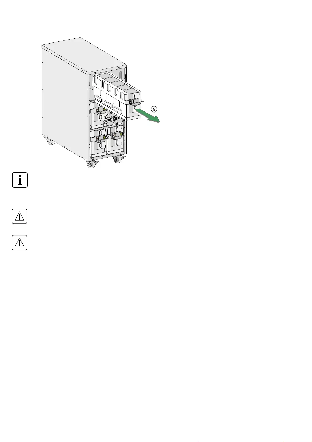
• Replacing the internal battery — TOWER 5-6KVA
The internal battery is heavy. Use caution when handling the heavy batteries.
The internal batteries are located behind the UPS front cover. The internal batteries are packaged together as
one unit for easier handling.
To replace the batteries in the UPS:
1. Remove the UPS front cover.
To remove the cover:
Remove the 2 fi xing screws on the bottom of
the cover.
Push upon the bottom of the cover and pull the
cover toward you to unclip it from the cabinet.
A ribbon cable connects the LCD control panel to the UPS. Do not pull on the cable or disconnect it.
6. UPS maintenance

Page 47
614-20306-00 — 9SX 0-6 KVA EMEA_EN
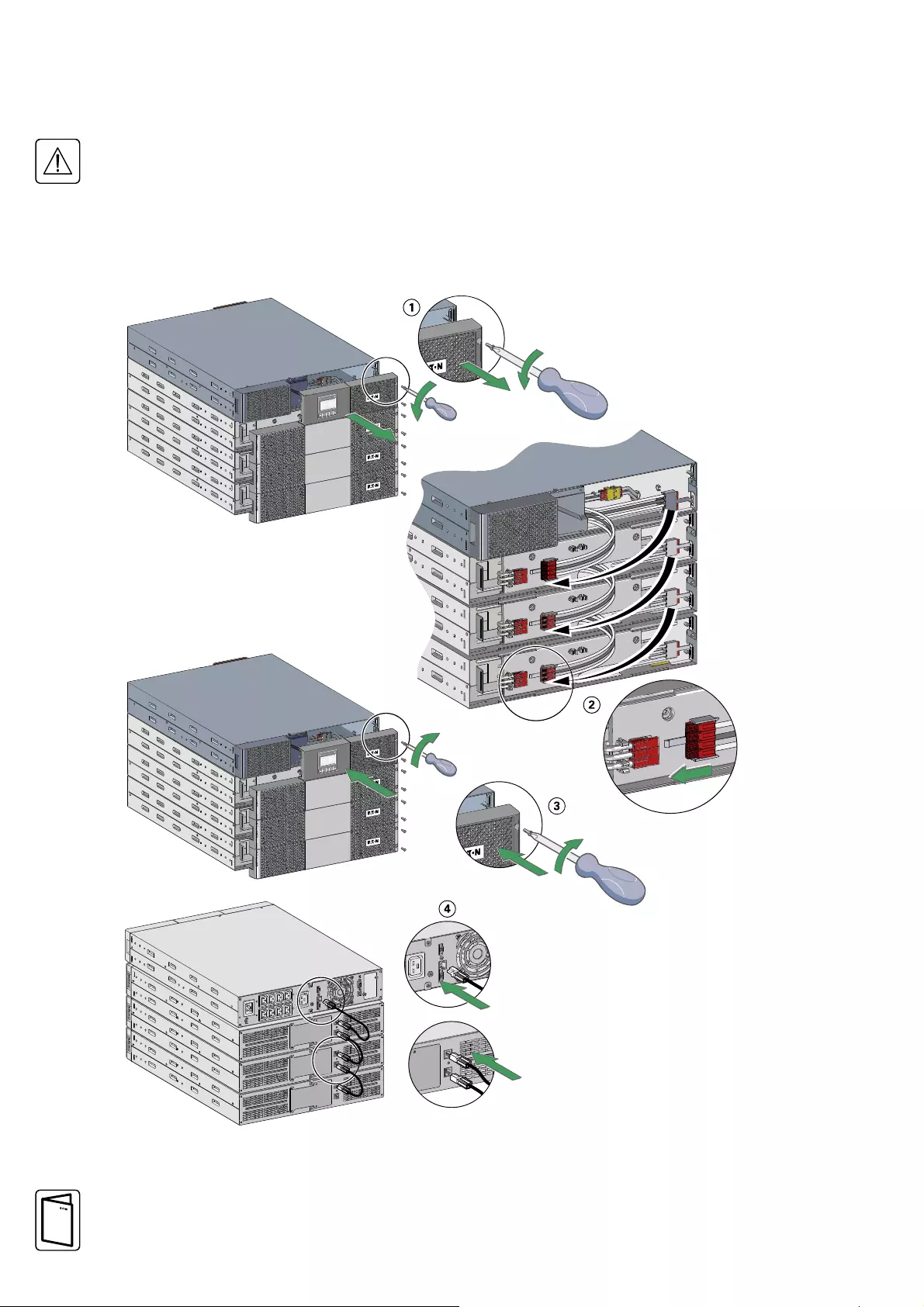
2. Disconnect the internal battery connector.
3. Disconnect one of the 4 battery trays.
Remove the plastic protection above the
connector and disconnect the battery tray.
4. Remove the metal fi xing part to free the battery
tray.
6. UPS maintenance
Page 48 614-20306-00 — 9SX 0-6 KVA EMEA_EN
6. UPS maintenance
5. Carefully pull the handle on the battery tray
and slide the battery package slowly out onto
a fl at, stable surface; use two hands to support
the battery package. See «Recycling the used
battery or UPS» on page 49 for proper disposal.
Verify that the replacement batteries have the same rating as the batteries being replaced.
Repeat step 3-4-5 if several battery tray need to be removed.
6. Slide the new battery package into the cabinet. Push the battery package in fi rmly.
7. Screw the metal part to fi x the battery tray.
Make sure main internal battery connector is disconnected.
8. Connect the battery tray and put back the plastic protection above the connector.
A small amount of arcing may occur when connecting the internal batteries. This is normal and will not harm
personnel. Connect the cables quickly and fi rmly.
9. Reconnect the internal battery connector. Press the two parts tightly together to ensure a proper connection.
10. Place the connector between the screw mounts and reinstall the retained screws.
11. Replace the UPS front cover.
To replace the cover, verify that the ribbon cable is protected, then insert the clips on the back of the cover
into the cabinet and push fi rmly to snap the cover into place.
Put back the 2 fi xing screws on the bottom of the cover.
12. Continue to «Testing New Batteries».

Page 49
614-20306-00 — 9SX 0-6 KVA EMEA_EN
6. UPS maintenance
• Replacing the EBM(s) (all models)
The EBM is heavy (see page 8). Lifting the cabinet into a rack requires a minimum of 2 people.
To replace the EBM(s):
1. Unplug the EBM power cable and battery detection cable from the UPS.
If additional EBM(s) are installed, unplug the EBM power cable and battery detection cable from each
EBM.
2. Replace the EBM(s). See «Recycling the used equipment» on page 49 for proper disposal.
A small amount of arcing may occur when connecting an EBM to the UPS. This is normal and will not harm
personnel. Insert the EBM cable into the UPS battery connector quickly and fi rmly.
3. Plug the EBM cable(s) into the battery connector(s). Up to four EBMs may be connected to the UPS.
4. Verify that the EBM connections are tight and that adequate bend radius and strain relief exist for each
cable.
5. Connect the battery detection cable(s) to the connector of the UPS and of the EBM(s).
• Testing new batteries
To test new batteries:
1. Charge the batteries for 48 hours.
2. Press any button to activate the menu options.
3. Select Control then Start battery test.
The UPS starts a battery test if the batteries are fully charged, the UPS is in Normal mode with no active
alarms, and the bypass voltage is acceptable.
During the battery test, the UPS transfers to Battery mode and discharges the batteries for 10 seconds. The
front panel displays «Battery test in progress» and the percentage of the test completed.
6.5 Recycling the used equipment
Contact your local recycling or hazardous waste center for information on proper disposal of the used
equipment.
• Do not dispose of the battery or batteries in a fi re. Batteries may explode. Proper disposal of batteries is
required. Refer to your local codes for disposal requirements.
• Do not open or mutilate the battery or batteries. Released electrolyte is harmful to the skin and eyes. It
may be toxic.
Do not discard the UPS or the UPS batteries in the trash. This product contains sealed, lead acid batteries and
must be disposed of properly. For more information, contact your local recycling/reuse or hazardous waste
center.
Do not discard waste electrical or electronic equipment (WEEE) in the trash. For proper disposal, contact your
local recycling/reuse or hazardous waste center.

Page 50 614-20306-00 — 9SX 0-6 KVA EMEA_EN
7. Troubleshooting
The Eaton 9SX are designed for durable, automatic operation and also alert you whenever potential operating
problems may occur. Usually the alarms shown by the control panel do not mean that the output power is
affected. Instead, they are preventive alarms intended to alert the user.
• Events are silent status information that are recorded into the Event log. Example = «AC freq in range».
• Alarms are recorded into the Event log and displayed on the LCD status screen with the logo blinking.
Some alarms may be announced by a beep every 3 seconds. Example = «Battery low».
• Faults are announced by a continuous beep and red LED, recorded into the Fault log and displayed on the
LCD with a specifi c message box. Example = Out. short circuit.
Use the following troubleshooting chart to determine the UPS alarm condition.
7.1 Typical alarms and faults
To check the Event log or Fault log:
1. Press any button on the front panel display to activate the menu options.
2. Press the button to select Event log or Fault log.
3. Scroll through the listed events or faults.
The following table describes typical conditions.
Conditions Possible cause Action
Battery mode
LED is On.
1 beep every 10 seconds.
A utility failure has occurred and the
UPS is in Battery mode.
The UPS is powering the equipment
with battery power. Prepare your
equipment for shutdown.
Battery low The UPS is in Battery mode and the
battery is running low.
This warning is approximate, and the
actual time to shutdown may vary
significantly.
Depending on the UPS load and
number of Extended Battery Modules
(EBMs), the «Battery Low» warning
may occur before the batteries reach
20% capacity.
LED is On.
1 beep every 3 seconds.
No battery The batteries are disconnected. Verify that all batteries are properly
connected.
If the condition persists, contact your
service representative.
LED is On.
Beep continuous.
Battery fault The battery test is failed due to bad or
disconnected batteries, or the battery
minimum voltage is reached in ABM®
cycling mode.
Verify that all batteries are properly
connected. Start a new battery test:
if the condition persists, contact your
service representative.
LED is On.
Beep continuous.
The UPS does not
provide the expected
backup time.
The batteries need charging or service. Apply utility power for 48 hours to
charge the batteries. If the condition
persists, contact your service
representative.
Bypass mode An overload or a fault has occurred, or
a command has been received and the
UPS is in Bypass mode.
Equipment is powered but not
protected by the UPS.
Check for one of the following alarms:
overtemperature, overload or UPS
failure.
LED is on.
Power overload Power requirements exceed the
UPS capacity (greater than 100% of
nominal; see in table 6 on page 54 for
specific output overload ranges).
Remove some of the equipment from
the UPS.
The UPS continues to operate, but
may switch to Bypass mode or shut
down if the load increases.
The alarm resets when the condition
becomes inactive.
LED is On.
Beep continuous.

Page 51
614-20306-00 — 9SX 0-6 KVA EMEA_EN
7. Troubleshooting
UPS overtemperature The UPS internal temperature is too
high or a fan has failed.
At the warning level, the UPS generates
the alarm but remains in the current
operating state.
If the temperature rises another 10 °C,
the UPS transfers to Bypass mode or
shuts down if Bypass is unusable.
If the UPS transferred to Bypass
mode, the UPS will return to normal
operation when the temperature drops
5 °C below the warning level.
If the condition persists, shut down
the UPS.
Clear vents and remove any heat
sources. Allow the UPS to cool. Ensure
the airflow around the UPS is not
restricted. Restart the UPS.
If the condition continues to persist,
contact your service representative.
LED is On.
1 beep every 3 seconds.
The UPS does not start. The input source is not connected
correctly.
Check the input connections.
The Remote Power Off (RPO) switch is
active or the RPO connector is missing.
If the UPS Status menu displays the
«Remote Power Off» notice, inactivate
the RPO input.
After 4 years of operation, the UPS
will provide a battery replacement
notification reminding you that your
batteries are nearing the end of their
useful life.
See «6.3 When to replace batteries».
7.2 Silencing the alarm
Press the ESC (Escape) button on the front panel display to silence the alarm. Check the alarm condition and
perform the applicable action to resolve the condition. If the alarm status changes, the alarm beeps again,
overriding the previous alarm silencing.
7.3 Service and support
If you have any question or problem with the UPS, call your distributor, your local service representative or
connect to: powerquality.eaton.com.
Please have the following information ready when you call for service:
• Model number
• Serial number
• Firmware version number
• Date of failure or problem
• Symptoms of failure or problem
• Customer return address and contact information
If repair is required, you will be given a Returned Material Authorization (RMA) number. This number must
appear on the outside of the package and on the Bill Of Lading (if applicable). Use the original packaging
or request packaging from the Help Desk or distributor. Units damaged in shipment as a result of improper
packaging are not covered under warranty. A replacement or repair unit will be shipped, freight prepaid for
all warrantied units.
For critical applications, immediate replacement may be available. Call the Help Desk for the dealer or
distributor nearest you.
7.4 CE compliance contact
• Eaton I.F. SAS — 110 Rue Blaise Pascal — 38330 Montbonnot St Martin – France.

Page 52 614-20306-00 — 9SX 0-6 KVA EMEA_EN
8. Specifications
8.1 Model specifi cations
Table 1. Power Module model list
Description / Part
Number
Power ratings
9SX700I 700VA / 630W
9SX1000I 1000VA / 900W
9SX1000IM 1000VA / 900W
9SX1500I 1500VA / 1350W
9SX2000I 2000VA / 1800W
9SX3000I 3000VA / 2700W
9SX3000IM 3000VA / 2700W
9SX5KI 5000VA / 4500W
9SX6KI 6000VA / 5400W
Table 2. Extended Battery Module model list
Part Number Configuration Battery voltage For power ratings
9SXEBM36T Tower 36Vdc 1000VA
9SXEBM48T Tower 48Vdc 1500VA
9SXEBM96T Tower 96Vdc 2000-3000VA
9SXEBM240T Tower 240Vdc 5000-6000VA
9SXEBM36R Rack 36Vdc 1000VA
9SXEBM48R Rack 48Vdc 1500VA
9SXEBM72R Rack 72Vdc 2000-3000VA

Page 53
614-20306-00 — 9SX 0-6 KVA EMEA_EN
8. Specifications
Table 3. Weights and dimensions
Part Number (UPS) Weights (kg) Dimensions (mm) W x H x D
9SX700I 11.5 160 x 252 x 357
9SX1000I 14.8 160 x 252 x 387
9SX1000IM 14.8 160 x 252 x 387
9SX1500I 18.5 160 x 252 x 437
9SX2000I 33.3 214 x 346 x 412
9SX3000I 33.4 214 x 346 x 412
9SX3000IM 33.4 214 x 346 x 412
9SX5KI 65.5 244 x 575 x 542
9SX6KI 65.5 244 x 575 x 542
9SX1000IR 15.7 438 x 86.5 x 438
9SX1500IR 18.4 438 x 86.5 x 438
9SX2000IR 26.5 438 x 86.5 x 608
9SX3000IR 26.5 438 x 86.5 x 608
Part Number (EBM) Weights (kg) Dimensions (mm) W x H x D
9SXEBM36T 19 160 x 252 x 387
9SXEBM48T 24.5 160 x 252 x 387
9SXEBM96T 48.7 214 x 346 x 412
9SXEBM240T 104.9 244 x 575 x 542
9SXEBM36R 22.2 438 x 86.5 x 438
9SXEBM48R 27.4 438 x 86.5 x 438
9SXEBM72R 40.5 438 x 86.5 x 608
Table 4. Electrical input
Nominal frequency 50/60Hz auto-sensing
Frequency range 40-70Hz before transfer to battery
Bypass voltage range -20% / +15% of nominal value (default)
Part Number Default input
(Voltage/Current)
Input nominal voltages Input voltage window
9SX700I 230V / 3.5A
200V, 208V, 220V, 230V,
240V
at 100% load: 190-276V
at ≤25% load: 120-276V
9SX1000I 230V / 4.9A
9SX1000IM 230V / 4.9A
9SX1000IR 230V / 4.9A
9SX1500I 230V / 7.2A
9SX1500IR 230V / 7.2A
9SX2000I 230V / 9.5A
200V, 208V, 220V, 230V,
240V
at 100% load: 200-276V
at ≤25% load: 140-276V
9SX2000IR 230V / 9.5A
9SX3000I 230V / 13.9A
9SX3000IM 230V / 13.9A
9SX3000IR 230V / 13.9A
9SX5KI 230V / 21.7A 208V, 220V, 230V, 240V at 100% load: 180-276V
at ≤25% load: 120-276V
9SX6KI 230V / 28.5A

Page 54 614-20306-00 — 9SX 0-6 KVA EMEA_EN
8. Specifications
Table 5. Electrical input connections
Part Number Input connection Input cable
9SX700I IEC C14-10A NA (1)
9SX1000I
9SX1000IM
9SX1000IR
9SX1500I
9SX1500IR
9SX2000I
9SX2000IR
9SX3000I IEC C20-16A Schuko 16A to IEC320/16A (2)
9SX3000IM
9SX3000IR
9SX5KI Hardwired NA
9SX6KI
(1) If used in 2W + PE confi guration, customer should use input power cord IEC C13 to NEMA 6-15P or L6-15P.
(min18 AWG / 3C , min 300V, 105 °C ,min 1.5 m, max 4.5 m)
(2) If used in 2W + PE confi guration, customer should use input power cord IEC C19 to NEMA 6-20P or L6-20P.
(min14 AWG / 3C , min 300V, 105 °C , min 1.5 m, max 4.5 m)
Table 6. Electrical output
All models Normal mode High Efficiency mode Battery mode
Voltage regulation ±2% ±3%
Efficiency 700VA 87% 92% 79%
1KVA 88% 94% 82%
1.5KVA 91% 96% 82%
2KVA 92% 97% 84%
3KVA 92% 97% 84%
5KVA 94% 98% 92%
6KVA 94% 98% 92%
Frequency regulation Sync with line ±5% of nominal line frequency
(outside this range: ±0.5% of auto-selected nominal
frequency)
±0.5% of auto-selected
nominal frequency
Nominal output 200/208/220/230/240V for 0-3KVA (voltage configurable)
208/220/230/240V for 5-6KVA
Frequency 50 or 60Hz. autosensing or configurable as a frequency converter
0-3KVA 5-6KVA
Output overload
(Online mode)
102%~130%* 12 s 120 s
130%~150%* 2 s 30 s
>150%* Shutdown
immediately**
0.1 s**
Output overload
(Battery mode)
102%~130%* 12 seconds 120 s
130%~150%* 2 seconds 30 s
>150%* Shutdown
immediately**
0.1 s**
Output overload
(Bypass mode)
102%~110%* Overload warning
110%~130%* Shutdown after 5 mins
130%~150%* Shutdown after 15 s Shutdown after 15 s
>150%* Shutdown after 300 ms
Voltage waveform Sine wave
Harmonic distortion < 3% THDV on linear load
< 5% THDV on non-linear load
Power factor Up to 0.9
Load crest ratio Up to 3:1
* Percent is based on nominal Watt/VA
** Behaviour can change (see output mode in In/Out settings of the section 4.4)
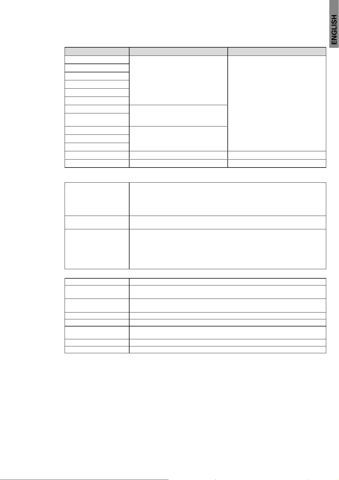
Page 55
614-20306-00 — 9SX 0-6 KVA EMEA_EN
8. Specifications
Table 7. Electrical output connection
Part Number Output connection Output cables
9SX700I (3) IEC10A
(2) IEC10A Group 1
(1) IEC10A Group 2
(2) IEC10A 2 meters
9SX1000I
9SX1000IM
9SX1000IR
9SX1500I
9SX1500IR
9SX2000I (4) IEC10A
(2) IEC10A Group 1
(2) IEC10A Group 2
9SX2000IR
9SX3000I (4) IEC10A + (1) IEC16A
(2) IEC10A Group 1
(2) IEC10A Group 2
9SX3000IM
9SX3000IR
9SX5KI NA NA
9SX6KI NA NA
Table 8. Environmental and safety
Certifications IEC/EN 62040-1
IEC/EN 62040-2: Cat. C1
IEC/EN 62040-3
UL1778 5th edition (for 0-3KVA)
CSA 22.2 (for 0-3KVA)
EMC (Emissions)* CISPR22 Class B
FCC part 15 Class B / ICES-003 (for 0-3KVA)
EMC (Immunity) IEC 61000-4-2, (ESD): 8 kV Contact Discharge / 15 kV Air Discharge
IEC 61000-4-3, (Radiated field): 10 V/m
IEC 61000-4-4, (EFT): 4 kV
IEC 61000-4-5, (Surges): 2 kV Differentiel Mode / 4 kV Common Mode
IEC 61000-4-6, (Electromagnetic field): 10 V
IEC 61000-4-8, (Conducted magnetic field): 30 A/m
* for output cable < 10m.
Agency markings CE / cULus (for 0-3KVA) / EAC / RCM / KC / Energy Star
Operating temperature 0 to 40 °C (32 to 104 °F) in Online mode, with linear derating for altitude
Note: thermal protection switches load to Bypass in case of overheating.
Storage temperature 0 to 40 °C (32 to 104 °F) with batteries
-25 to 55 °C (-13 to 130 °F) without batteries
Transit temperature -25 to 55 °C (-13 to 130 °F)
Relative humidity 0 to 96% no condensing
Operating altitude Up to 3,000 meters (9,843 ft) above sea level, no derating for 35 °C (95 °F)
room temperature
Transit altitude Up to 10,000 meters (32,808 ft) above sea level
Audible noise < 50 dBA at 1 meter typical
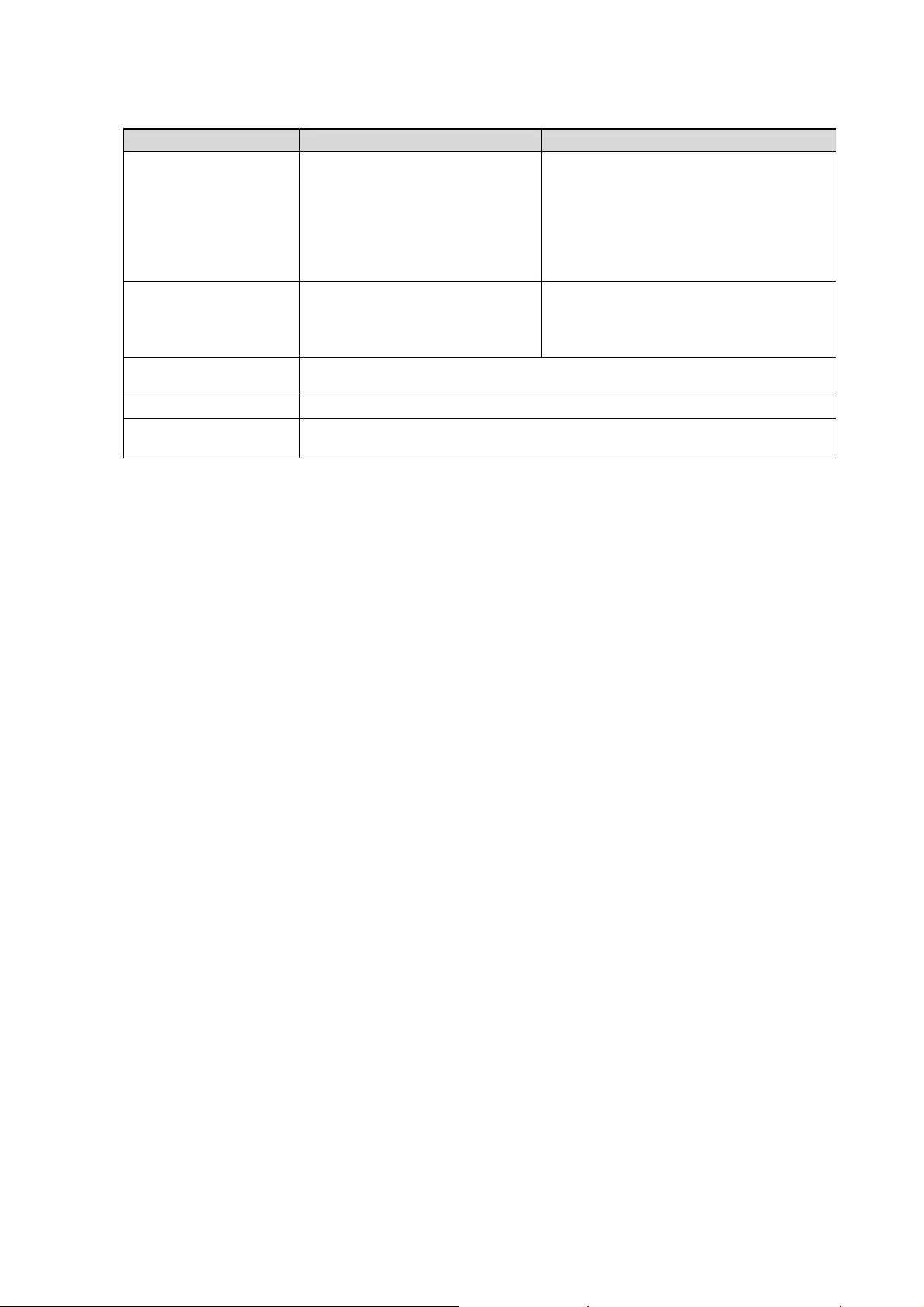
Page 56 614-20306-00 — 9SX 0-6 KVA EMEA_EN
8. Specifications
Table 9. Battery
Internal batteries EBM
Tower configuration 700VA: 24Vdc — 2 x 12V. 9Ah
1000VA: 36Vdc — 3 x 12V. 9Ah
1500VA: 48Vdc — 4 x 12V. 9Ah
2000VA: 96Vdc — 8 x 12V. 7Ah
3000VA: 96Vdc — 8 x 12V. 9Ah
5KVA: 240Vdc — 20 x 12V. 7Ah
6KVA: 240Vdc — 20 x 12V. 7Ah
9SXEBM36T: 36Vdc — 2 x 3 x 12V. 9Ah
9SXEBM48T: 48Vdc — 2 x 4 x 12V. 9Ah
9SXEBM96T: 96Vdc — 2 x 8 x 12V. 9Ah
9SXEBM240T: 240Vdc — 2 x 20 x 12V. 7Ah
Rack configuration 1000VA: 36Vdc — 3 x 12V. 9Ah
1500VA: 48Vdc — 4 x 12V. 9Ah
2000VA: 72Vdc — 6 x 12V. 7Ah
3000VA: 72Vdc — 6 x 12V. 9Ah
9SXEBM36R: 36Vdc — 2 x 3 x 12V. 9Ah
9SXEBM48R: 48Vdc — 2 x 4 x 12V. 9Ah
9SXEBM72R: 72Vdc — 2 x 6 x 12V. 9Ah
Ty p e Sealed, maintenance-free, valve-regulated, lead-acid, with minimum 3-year
float service life at 25 °C (77 °F)
Monitoring Advanced monitoring for earlier failure detection and warning
EBM battery cable
length
400 mm / 15.75 in

Page 57
614-20306-00 — 9SX 0-6 KVA EMEA_EN
9. Glossary
Bypass AC source Source supplying the bypass line. The equipment can be transferred to the
by-pass line if an overload occurs on the UPS output, for maintenance or in the
event of a malfunction.
Frequency converter Operating mode used to convert the AC-power frequency between the UPS input
and output (50Hz -> 60Hz or 60Hz -> 50Hz).
Low-battery warning This is a battery-voltage level indicating that battery power is low and that the user
must take action to prevent the imminent break in the supply of power to the load.
Backup time Time during which the load can be supplied by the UPS operating on battery
power.
Load Devices or equipment connected to the UPS output.
HE mode Operating mode by which the load is supplied directly by the AC source if it is
within the tolerances defi ned by the user. This mode reduces the consumption
of electrical power.
Normal (double The normal UPS operating mode in which the AC source supplies the UPS which
conversion) mode in turn supplies the connected loads (after electronic double conversion).
Normal AC source Normal source of power for the UPS.
Relay contacts Contacts supplying information to the user in the form of signals.
UPS Uninterruptible Power Supply.

Page 58 614-20306-00 — 9SX 0-6 KVA EMEA_EN

Page 59
614-20306-00 — 9SX 0-6 KVA EMEA_EN

Page 60 614-20306-00 — 9SX 0-6 KVA EMEA_EN
File Specifications:1759/1759975-9sx_series.pdf file (14 Jul 2023) |
Accompanying Data:
Eaton 9SX Series UPS PDF Manual (Updated: Friday 14th of July 2023 02:43:33 AM)
Rating: 4.6 (rated by 36 users)
Compatible devices: Ellipse 375, 9E-IN 1K, 9PX 1:1, 93E 30IAC-D, Power Xpert 9395P 250 kVA, Tower 6KS, 700VA, 5S 550.
Recommended Documentation:
Manual (Text Version):
(Ocr-Read Summary of Contents of some pages of the Eaton 9SX Series Document (Main Content), UPD: 14 July 2023)
-
90, 84 Mode 3-3(single source) 1. Input: connect mian-ground cable (PE) to chassis first; short ‘UPS input terminal N/N’ with ‘busbar #1’, then connect AC cable(N); connect ‘UPS input terminal L1/L2/L3’ with AC cable(L1/L2/L3) and ‘jumper cable’ by back to back mounted; then fix ‘jumper cable’ to ‘UPS bypass terminal L1/L2/L3’. 2. Output: connect ground cable (PE) to chassis first; short ‘UPS output terminal N/N’ with ‘…
-
71, Eaton 9SX Series 65 True online double-conversion technology with high power density, utility frequency independence, and generator compatibility. Selectable High Efficiency mode of operation. Standard communication options: one RS232 communication port, one USB communication port, one dry in port and dry out port. Optional connectivity cards with enhanced communication capabilities. Firmware that is easi…
-
32, 26 4.2 与外部电池组 与外部电池组与外部电池组 与外部电池组(EBM)的接线 的接线的接线 的接线 本系列的‘外部电池组(EBM)’为选配模块,能够为 UPS 提供更长的备电时间。 1. 连接 UPS 前,一定确保电池线与外部电池组 (EBM)断开。 2. 连接或断开外部电池组(EBM)前,请确保 UPS 完全关闭。 3. 连接外部电池组(EBM)前,请确认电池节数和…
-
55, 49 7.4.4 UPS 并机 并机并机 并机 1. 一般操作需要遵循单机操作要求 2. 并机开机 市电开机: • 接入市电后,按下并机系统中任意一台 UPS 开机键 1 秒以上,系统所有的机 器将同时开机,然后跳转到逆变状态。 • 并机系统中一台 UPS 已经开机到逆变状态的情况下,再给其余 UPS 连接市电, 刚上电的 UPS 会自动开机到逆变状态。 电池开…
-
5, 6. 非专业人士请勿打开或损毁蓄电池,因为电池中的电解液含有强酸等危险物质,会 对皮肤和眼睛造成伤害。如果不小心接触到电解液,应立即用大量的清水进行清洗, 并去医院检查。 7. 请勿将电池正负极短路,否则会导致电击或着火。 使用保养 使用保养使用保养 使用保养 1. 使用环境及保存方法对本产品的使用寿命及可靠性有一定…
-
42, Eaton 9SX Series 36 Dry in & Dry out (干接点) (干接点)(干接点) (干接点) Dry in 是光耦合输入接口,连接外部开关,自定义设置干接点输入功能后,可 以执行开机、关机等操作。 Dry out 是继电器输出,接口为常开,可以用来指示 UPS 负载过载、电池模式、 电…
-
33, Eaton 9SX Series 27 本系列的外部电池组(EBM)的附件线包含: 数量(个) 用途 图示 外部电池组 侦测线(RJ45) 1 侦测 EBM 外部电池组 连接线 1 连接 EBM 到 UPS 外部电池组 扩展线 2 并联扩展 EBM UPS 连接外部电池组(EBM)的电缆接线的示意图如下: 备注: 如果用户自行配置‘外接电池’,请依照上述的接线原理及章节 3.2 进行电池 的配线。 …
-
81, 75 2. Install the mounting ears. Lock the left/right mounting ears into the UPS with 8pcs M4 flat screws (make sure the correct-direction of the mounting ears as below) Note: This UPS provided another two fix-position for the mounting ears as to meet a special installation depth requirements(as below): 3. Take the UPS to the rail kit and push backwards; secure to the cabinet posts with 4pcs M5 screws…
-
105, 99 6. Communication ports Computer ports The UPS provides USB and RS232 communication ports. For practical applications, please use the communication cable provided by the accessory to connect to the corresponding communication port. RS-232 port communication default parameters:2400, 8, 1, 0.(The baud rate is 2400, 8 data bits, 1 stop bit, no parity) If USB and RS232 are connected …
-
47, 41 7.2.4 主菜单页面 主菜单页面主菜单页面 主菜单页面 在主页面下,点击左下角菜单图标,即可进入主菜单页面。 在主菜单页面,可根据需求点击相应图标进行操作。 屏幕保护 • 在任意页面下,当 5 分钟内无任何按键操作时,LCD 背光灯会自动熄灭,LCD 进入屏幕休眠。该模式下触摸屏幕可以重新点亮 LCD,回到之前的页面。 • 在任意页面�…
-
86, 80 Please refer to the following table for conductor’s terminal selection: Recommended circuit breaker and contactor current specifications: Model name Input mode Breaker Contactor 9SX 15KPM(AU) DXRT 15KS-IN 1 phase main input D type 125A ≥125A 3 phase main input D type 63A ≥63A 1 phase bypass input D type 100A ≥100A 3 phase bypass input D type 40A ≥40A 9SX 20KPM(AU) DXRT 20KS-IN 1 phase main input D type 160A ≥160A 3 phase main inp…
-
46, 40 7.2.3 主页面及弹窗 主页面及弹窗主页面及弹窗 主页面及弹窗 标号 名称 说明 ① 故障或告警信息 没有故障或者告警信息时为空白 存在故障或者告警信息时在此位置逐条显示 ② 输入状态 下部图标有旁路、市电和电池三个输入状态显示 高亮颜色的文字代表当前的输入状态 ③ 系统状态 颜色区分系统状态�…
-
45, 39 7.2.2 引导页面 引导页面引导页面 引导页面 本产品在第一次使用时、开机画面结束之后,会进入引导页面,引导用户进行 初始化设置,包括语言选择,密码设置、时间设置以及输出电压设置。 设置时请先点击密码框,出现光标后在屏幕右侧小键盘输入您的四位数字密码, 确认密码操作与设置时�…
-
20, 14 • 塔式安装: 塔式安装:塔式安装: 塔式安装: 本模块的 LCD 支持自重力感应,LCD 界面可以自动调整显示方向。 从附件中取出 ‘ 塔式安装脚架 ’ ,锁紧到箱体两侧的螺芽孔(如下图示)。 安装时需注意,UPS 模块的显示屏应在上部(如下图示)。 3.3.2 外部电池组 外部电池组外部电池组 外部电池组…
-
26, 20 三进三出(主旁同源): 1. 输入:‘地线(PE)’先接入机箱,‘铜排#1’短接 UPS 输入端子的 N 并接入‘中线 (N)’,然后‘主输入的相线(L1/L2/L3)’分别搭配‘跳线’以背靠背的方式接入 UPS 输入端子的 L1/L2/L3,最后将‘跳线’的另一头分别接入旁路输入端子的 L1/L2/L3。 2. 输出:‘地线(PE)’先接入机箱,‘铜排#1’短接 UPS 输出端子的 N 并接入‘中线 (N)’,…
-
Eaton 9SX Series User Manual
-
Eaton 9SX Series User Guide
-
Eaton 9SX Series PDF Manual
-
Eaton 9SX Series Owner’s Manuals
Recommended: Aspire 3300S, 8109.282 Salvador, TA1FRI-1S, 5070 — Cell Phone 4.3 MB, A1008
Links & Tools
Operating Impressions, Questions and Answers: