Инструкция по эксплуатации для стиральной машины Ardo AE, SE
Комплектующие для стиральной машины
ТЭН
| Модель ТЭНа | фото |
|---|---|
| Тэн для стиральной машины 0305 1950 W 200 мм изогнутый Thermowatt |  |
Манжет люка
| Модель манжета люка | фото |
|---|---|
| Манжета люка для Ardo AE, SE |  |
Ремни
| Модель ремня | фото |
|---|---|
| Ремень приводной для Ardo AE, SE |  |
Подшипники
| Модель подшипника | фото |
|---|---|
| Подшипник барабана для Ardo AE, SE |  |
Сальники
| Модель сальника | фото |
|---|---|
| Сальник бака для Ardo AE, SE |  |
Ручка люка
| Модель ручки люка | фото |
|---|---|
| РУЧКА ДВЕРЦЫ ЛЮКА ДЛЯ СТИРАЛЬНОЙ МАШИНЫ АРДО (ARDO) |  |
Электронный модуль
| Модель электронного модуля | фото |
|---|---|
| МОДУЛЬ ЭЛЕКТРОННЫЙ, ПЛАТА УПРАВЛЕНИЯ ДЛЯ СТИРАЛЬНОЙ МАШИНЫ АРДО (ARDO) AE1000X | 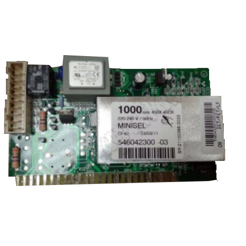 |
Блокировка люка
| Модель блокировки люка | фото |
|---|---|
| Замок люка (убл) для Ardo | 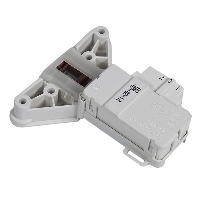 |
МОДЕЛЬ: АЕ 833, SE 800X, SE 810, SE 1000Х, SE 1010, АЕ 810, АЕ 800Х, АЕ 1033, АЕ 1010, АЕ 1000Х, АЕ 1200Х, АЕ 1400Х
ОСНОВНЫЕ ФУНКЦИИ СТИРАЛЬНОЙ МАШИНЫ
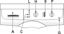
А список программ
С кнопки дополнительных функций
G кнопка вкл/выкл
Н ручка выбора скорости отжима
L кнопка пуска программы
Р ручка программатора и термостата
S контрольные лампочки выполнения фаз программы
ПОЛЬЗОВАНИЕ СТИРАЛЬНОЙ МАШИНОЙ
▼ ЦИКЛ СТИРКИ:
(последовательность операций для выполнения цикла стирки)
1. Откройте дверцу люка.
2. Загрузите белье в барабан и закройте дверцу люка.
Внимание: Запрещается перегружать стиральную машину. Не рекомендуется стирать в машине вещи, поглощающие большое количество воды, например ковры.
3. В соответствующие отделения засыпьте стиральный порошок с низким ценообразованием для автоматических стиральных машин и залейте кондиционер (см. раздел «Применение стирального порошка»).
4. Закройте контейнер для стирального порошка. Во избежание утечки воды во время работы машины не вынимайте контейнер для стирального порошка
5. Вставьте вилку в розетку и откройте кран подачи воды. Нажмите кнопку вкл/выкл G; загорится контрольная лампочка, соответствуюгщя последней установленной программе
6. При помощи ручки программатора Р установите выбранные программу и температуру, соответствующие типу ткани, из которой изготовлено предназначенное для стирки белье (см. раздел «ТАБЛИЦА ПРОГРАММ»).
7. При помощи ручки Н выберите скорость отжима (см. «УСТАНОВКА СКОРОСТИ ОТЖИМА»)
8. При помощи кнопок С установите требуемые функции (см. «ДОПОЛНИТЕЛЬНЫЕ ФУНКЦИИ») При нажатии кнопки загорятся.
9. Для пуска программы нажмите кнопку L (см. «КНОПКА ПУСКА»)
10. По завершении программы стирки нажмите кнопку вкл/выкл G, чтобы выключить стиральную машину.
11. Подождите 2 минуты, чтобы отключилось блокировочное устройство. Откройте дверцу люка и выньте белье.
12. Сухими руками выньте вилку из розетки.
13. Закройте кран подачи воды
▼ УСТАНОВКА СКОРОСТИ ОТЖИМА:
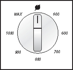
В стиральной машине предусмотрен широкий выбор скоростей отжима, которые устанавливаются в соответствии с выбранной программой перед ее пуском. Для изменения скорости отжима достаточно просто установить ручку Н в положение, соответствующее требуемому количеству оборотов. Если Вы ютите отключить отжим, ручку следует установить в положение .
ПРИМЕЧАНИЕ: Максимальная скорость отжима меняется в зависимости от модели и указана в разделе’Технические характеристики* Максимальная скорость отжима, предусмотренная для каждой программы, указана в таблице программ (если будет установлена скорость, превьшающая ото значение, стиральная машина все равно осуществит отжим на максимально допустимой для данной программы скорости)
Система защиты от дисбаланса при отжиме:
Эта стиральная машина оснащена специальной системой электронного контроля правильной балансировки загрузки Благодаря наличию этой системы перед каждым отжимом белье распределяется в барабане максимально равномерно В случае неправильного распределения белья, для обеспечения надежности скорость заключительного отжима снижается, а в случае повышенного дисбаланса заключительный отжим не производится.
ПОЛЬЗОВАНИЕ СТИРАЛЬНОЙ МАШИНОЙ
▼ КНОПКА ПУСКА:
После установки требуемой программы следует нажать эту кнопку, и машина начнет выполнение цикла стирки. При этом загорится кнопка L, указывая на начало выполнения цикла стирки.
▼ ОСТАНОВКА СТИРАЛЬНОМ МАШИНЫ:
Функция остановки предназначена для изменения программы стирки Если по какой-либо причине вовремя выполнения цикла стирки Вам понадобится изменить программу стирки, или Вы захотите добавить в машину белье, достаточно просто установить ручку программатора в положение “STOP» (остановка) (кнопка “start” начнет мигать) Затем при помощи ручки программатора установите новую программу и нажмите кнопку «START» (пуск) Перед тем как машина вновь начнет выполнять цикл стирки, вода из бака будет слита. ПРИМЕЧАНИЕ: Перед тем как снова включить машину, проверьте наличие стирального порошка в соответствующих отделениях, и при необходимости добавьте его.
ВНИМАНИЕ! Рекомендуется использовать данную функцию только в случаях крайней необходимости и не позднее, чем через 5 минут после начала выполнения программы Перед тем как открыть дверцу люка после остановки, следует подождать 2 минуты, чтобы отключилось блокировочное устройство.
ДОПОЛНИТЕЛЬНЫЕ ФУНКЦИИ
Предварительная стирка
При нажатии этой кнопки включается функция предварительной стирки при максимальной температуре 40°С.
Эта функция может использоваться только для программ стирки «ХЛОПОК» и «СИНТЕТИКА»
При выборе этой функции машина выполняет сначала ускоренную стирку при 40:С, а затем основную стирку при температуре, установленной пользователем Примечание: При использовании функции предварительной стирки порошок следует засыпать в отделения I и II контейнера для стирального порошка. Если нужно выполнить только основную стирку порошок следует засыпать в отделение II.
Дополнительное полоскание:
Стиральная машина спроектирована таким образом, чтобы расход воды был минимальным. При нажатии этой кнопки машина выполнит дополнительное полоскание. Эту функцию рекомендуется использовать в районах с очень мягкой водой, или в случае, если по окончании цикла стирки Вы замечаете в контейнере остатки стирального порошка.
Примечание: Использование дополнительных функций обусловлено установленной программой, поэтому, если данной программой не допускается использование какой-либо функции, нажать соответствующую кнопку будет невозможно (см. «ТАБЛИЦУ ПРОГРАММ»).
▼ КОНТРОЛЬ ВЫПОЛНЕНИЯ ФАЗ ПРОГРАММЫ:
На рисунке приведены 5 основных фаз цикла стирки: ПРЕДВАРИТЕЛЬНАЯ СТИРКА, ОСНОВНАЯ СТИРКА, ПОЛОСКАНИЕ, ОТЖИМ, ОКОНЧАНИЕ.
Во время выполнения цикла каждая из этих функций будет обозначаться включением соответствующей контрольной лампочки. Таким образом, можно узнать какая фаза цикла выполняется в данный момент.
По окончании отжима соответствующая контрольная лампочка будет гореть в течение примерно 2 минут, что соответствует времени, необходимому для отключения блокировочного устройства дверцы люка. Затем загорится контрольная лампочка «ОКОНЧАНИЕ»
После этого следует нажать кнопку вкл/выкл G, открыть дверцу люка и вынуть белье.
ТАБЛИЦЫ ПРОГРАММ
| Ручка программатора | Температура стирки | Символ на этикетке | Тип ткани | Отделение контейнера для стирального порошка | Скорость отжима | Кнопки дополнительных функции | |
| хлопок | 90° | Очень грязное белье из белой ткани с пятнами, в том числе органического происхсждения | |||||
| хлопок | 75° | Очень грязное постельное белье, рубашки, скатерти, полотенца из прочной ткани | Макс. (или ниже) | ||||
| хлопок* | 60° | Обычно загрязненные рубашки, скатерти, полотенца из прочной ткани | Макс. (или ниже) | ||||
| хлопок | 40° | Очень грязное белье из белой или цветной ткани с устойчивой окраской | Макс. (или ниже) | ||||
| хлопок | Макс. (или ниже) | ||||||
| 30° | Белье с нестойкой окраской, малозагрязненное белье | ||||||
| СИНТЕТИКА | 60° | Очень грязные вещи из синтетических тканей с устойчивой окраской | Макс. (или ниже) | ||||
| СИНТЕТИКА | 50° | Обычно загрязненные вещи из синтетических тканей с устойчивой окраской | 800 (или ниже) | ||||
| 800 (или ниже) | |||||||
| СИНТЕТИКА | 40° | Малозагрязненные вещи из синтетических тканей с нестойкой окраской | |||||
| СИНТЕТИКА | 30° | Малозагрязненные вещи из синтетических тканей с нестойкой окраской | 800 (или ниже) | ||||
| 800 (или ниже) | |||||||
| ДЕЛИКАТНЫЕ ТКАНИ | 40° | Вещи из тонкой хлопчатобумажной ткани, вискозы и тонких смешанных тканей | |||||
| ДЕЛИКАТНЫЕ ТКАНИ | 30° | Вещи из тонкой хлопчатобумажной ткани, вискозы и тонких смешанных тканей | 500 (или ниже) | ||||
| ДЕЛИКАТНЫЕ ТКАНИ | ХОЛОДНАЯ ВОДА | Вещи из шелка и тонких смешанных тканей | 500 (или ниже) | ||||
| 500 (или ниже) | |||||||
| ШЕРСТЬ | 40° | Вещи из шерстяных тканей, которые можно стирать в машине | |||||
| ШЕРСТЬ | 30° | Вещи из шерстяных тканей, которые можно стирать в машине | 800 (или ниже) | ||||
| ШЕРСТЬ | ХОЛОДНАЯ ВОДА | — | Вещи из шерстяных тканей, которые можно стирать в машине | 800 (или ниже) | |||
| 800 (или ниже) | |||||||
| РУЧНАЯ СТИРКА | 30° | Вещи, предназначенные для ручной стирки | |||||
| 800 (или ниже) |
дополнительная функция, действующая при включении кнопки предварительной стирки
возможность использования функции при выполнении программы
невозможность использования функции при выполнении программы
* Программа для определения класса энергопотребления в соответствии с нормой EN 60456
СИСТЕМА «EASY LOGIC»
Электронная стиральная машина оснащена системой «EASY LOGIC». Эта система автоматически определяет вес загружаемого белья и соответственно регулирует количество воды, используемой при стирке, что позволяет сократить расход воды и электроэнергии.
В случае если вес белья меньше рекомендуемой максимальной загрузки (см. «ТЕХНИЧЕСКИЕХАРАКТЕРИСТИКИ»), количество используемой для стирки воды сократится на 2 литра на каждый недостающий до максимальной загрузки килограмм белья.
В случае стирки половины или меньше половины максимальной загрузки, машина автоматически выполнит на одно полоскание меньше, чем это предусмотрено программой.
Примечание: Функция “EASY LOGIC» действует только для программ «ХЛОПОК».
ТЕХНИЧЕСКИЕ ХАРАКТЕРИСТИКИ
| МОДЕЛЬ | АЕ 633 | SE 600Х SEB10 |
SE 1000X SE 1010 |
AE 810 АЕ 600X |
AE 1033 |
AE 1010 AE 1000X |
AE 1200X | AE 140 OX | |
| ГАБАРИТЫ: | Ширина см: | 59.5 | 59.5 | 59.5 | 59.5 | 59.5 | 59.5 | 59.5 | 59.5 |
| Высота см: | 85.0 | 85.0 | 85.0 | 85.0 | 85.0 | 85.0 | 85.0 | 85.0 | |
| Глубина см: | 33.0 | 39.5 | 39 5 | 54.5 | 33.0 | 54.5 | 54.5 | 54.5 | |
| Рекомендуемая максимальная загрузка для стирки* | 3,5 Kg | 5,0 Kg | 5,0 Kg | 5,0 Kg | 3,5 Kg | 5,0 Kg | 5,0 Kg | 5,0 Kg | |
| 1,5 Kg | 2,5 Kg | 2,5 Kg | 2,5 Kg | 1,5 Kg | 2,5 Kg | 2,5 Kg | 2,5 Kg | ||
| 1,0 Kg | 1,0 Kg | 1,0 Kg | 1,0 Kg | 1,0 Kg | 1,0 Kg | 1,0 Kg | 1,0 Kg | ||
| Отжим макс.: (об/мин) | 800 | 800 | 1000 | 800 | 1000 | 1000 | 1200 | 1400 | |
| Давление воды | мин. 0,05 МПа — макс. 1 МПа | ||||||||
| Шанс, потребляемая мощлост^Электр (месите подключение | см маркировочную табличку |
* Для того чтобы белье, загружаемое в машину было хорошо сбалансировано и во избежание повышенной вибрации во время отжима, вес предназначенного для стирки белья должен быть не менее 1 кг.
1 EasyLogic PM2100 series User Manual NHA /2016
2 Legal Information The Schneider Electric brand and any registered trademarks of Schneider Electric Industries SAS referred to in this guide are the sole property of Schneider Electric SA and its subsidiaries. They may not be used for any purpose without the owner’s permission, given in writing. This guide and its content are protected, within the meaning of the French intellectual property code (Code de la propriété intellectuelle français, referred to hereafter as «the Code»), under the laws of copyright covering texts, drawings and models, as well as by trademark law. You agree not to reproduce, other than for your own personal, noncommercial use as defined in the Code, all or part of this guide on any medium whatsoever without Schneider Electric’s permission, given in writing. You also agree not to establish any hypertext links to this guide or its content. Schneider Electric does not grant any right or license for the personal and noncommercial use of the guide or its content, except for a non-exclusive license to consult it on an «as is» basis, at your own risk. All other rights are reserved. Electrical equipment should be installed, operated, serviced, and maintained only by qualified personnel. No responsibility is assumed by Schneider Electric for any consequences arising out of the use of this material. As standards, specifications, and designs change from time to time, please ask for confirmation of the information given in this publication.
3 Safety information Important information Read these instructions carefully and look at the equipment to become familiar with the device before trying to install, operate, service or maintain it. The following special messages may appear throughout this bulletin or on the equipment to warn of potential hazards or to call attention to information that clarifies or simplifies a procedure. The addition of either symbol to a Danger or Warning safety label indicates that an electrical hazard exists which will result in personal injury if the instructions are not followed. This is the safety alert symbol. It is used to alert you to potential personal injury hazards. Obey all safety messages that follow this symbol to avoid possible injury or death. Please note Electrical equipment should be installed, operated, serviced and maintained only by qualified personnel. No responsibility is assumed by Schneider Electric for any consequences arising out of the use of this material. A qualified person is one who has skills and knowledge related to the construction, installation, and operation of electrical equipment and has received safety training to recognize and avoid the hazards involved. NHA
4 Notices FCC This equipment has been tested and found to comply with the limits for a Class A digital device, pursuant to Part 15 of the FCC rules. These limits are designed to provide reasonable protection against harmful interference when the equipment is operated in a commercial environment. This equipment generates, uses, and can radiate radio frequency energy and, if not installed and used in accordance with the instruction manual, may cause harmful interference to radio communications. Operation of this equipment in a residential area is likely to cause harmful interference in which case the user will be required to correct the interference at his own expense. The user is cautioned that any changes or modifications not expressly approved by Schneider Electric could void the user s authority to operate the equipment. This digital apparatus complies with CAN ICES-3 (A) /NMB-3(A). 4 NHA
5 Table of Contents FCC…4 Safety precautions…9 Introduction…10 Meter Overview…10 Meter Features…10 Feature summary Mounting adaptors Measured parameters…12 Meter configuration…13 Firmware consideration…14 Hardware references…15 PM2100 meter models and accessories…15 Meter models…15 Meter accessories…15 Supplemental information…15 Panel Meter…15 LED Indicators…16 Meter mounting…16 Meter wiring…17 Direct connect voltage limits…17 Balanced system considerations…18 Balanced 3-phase Wye system with 2 CTs…19 Balanced 3-phase Wye or Delta system with 1CT…19 Serial communications…19 RS-485 wiring…19 Pulse output…19 I/O Modules…20 Configuring optional I/O module using ION Setup…21 Display and meter setup…23 Display overview…23 LED Indicators…23 Button functions…24 Meter screen menus…25 Remote meter setup…39 Overview…39 ION Setup…39 RS-485 port setup…39 Meter setup through RS Meter configuration using ION Setup…39 Viewing meter data…40 Viewing meter data from the display…40 Meters data screens…40 Meter data display screens…40 Using ION Setup to view or modify configuration data…41 Using software to view meter data…41 Power Monitoring Expert…42 NHA
6 PowerScada Expert…42 Modbus command interface…42 Alarms…43 Alarms overview…43 Alarm types…43 Unary alarms…43 Available unary alarms…43 Digital alarms…43 Digital alarm with setpoint delay…43 Available digital alarms…44 Standard alarms…44 Maximum allowable setpoint…45 Available standard alarms…46 Alarm priorities…47 Alarm setup overview…48 Built-in error-checking…48 LED alarm indicator…50 Configuring the LED for alarms using ION Setup…50 Alarms counters…50 Alarms rollover value…50 Meter logging…51 Logs overview…51 Setting up the data log…51 Saving the data log contents using ION Setup…51 Alarm log…52 Meter resets…53 Meter resets…53 Meter Initialization…53 Performing resets using ION Setup…53 Measurements and calculations…54 Meter Initialization…54 Real-time readings…54 Energy measurements…54 Min/max values…54 Power demand…54 Current demand…57 Timer…58 Active load timer…58 Meter operation timer…58 Run Time…58 Power quality…59 Harmonics overview…59 Total harmonic distortion…59 Displaying harmonics data…59 Maintenance and upgrades…61 Maintenance overview…61 Troubleshooting LED indicators…61 Meter memory…61 Meter battery…61 Viewing firmware version, model and serial number NHA
7 Firmware upgrades…62 Technical assistance…62 Verifying accuracy…63 Overview of meter accuracy…63 Accuracy test requirements…63 Signal and power source…63 Control equipment…63 Environment…63 Reference device or energy standard…64 Verifying accuracy test…64 Required pulses calculation for accuracy verification testing…65 Total power calculation for accuracy verification testing…66 Percentage error calculation for accuracy verification testing…66 Accuracy verification test points…66 Energy pulsing considerations…67 VT and CT considerations…67 Example calculations…68 Adjustments to allow energy pulsing at the pulse outputs…68 Typical sources of test errors…69 Power and power factor…70 Power and power factor…70 Current phase shift from voltage…70 Real, reactive and apparent power (PQS)…70 Power flow…71 Power factor (PF)…71 True PF and displacement PF…71 Meter specifications…74 Specifications…74 Mechanical characteristics…74 Electrical characteristics…74 Environmental characteristics…76 EMC (electromagnetic compatibility)*…76 Safety…76 RS-485 communications…77 Pulse output…77 Real-time clock…77 NHA
8
9 Safety precautions Safety precautions Installation, wiring, testing and service must be performed in accordance with all local and national electrical codes. DANGER HAZARD OF ELECTRIC SHOCK, EXPLOSION, OR ARC FLASH Apply appropriate personal protective equipment (PPE) and follow safe electrical work practices. See NFPA 70E in the USA, CSA Z462 or applicable local standards. Turn off all power supplying this device and the equipment in which it is installed before working on the device or equipment. Always use a properly rated voltage sensing device to confirm that all power is off. Do not exceed the device s ratings for maximum limits. Never short the secondary of a potential/voltage transformer (PT/VT). Never open circuit a current transformer (CT). Always use grounded external CTs for current inputs. Replace all devices, doors and covers before turning on power to this equipment. Failure to follow these instructions will result in death or serious injury. UNINTENDED OPERATION WARNING Do not use this device for critical control or protection applications where human or equipment safety relies on the operation of the control circuit. Failure to follow these instructions can result in death, serious injury, or equipment damage. NHA
10 Introduction Introduction Meter Overview The PM2100 series meters are digital meters that offer comprehensive 3-phase electrical instrumentation and load management facilities in a compact and rugged package. The meters offer value for the demanding needs of your energy monitoring and cost management applications. All meters in the PM2100 series range comply with Class 1, or Class 0.5S accuracy standards and feature high quality, reliability and affordability in a compact and easy to install format. Meter Features The PM2100 series meter supports many features, a few of the features are listed below: LED display screen: Intuitive self-guided navigation using three buttons LED display, with three lines of concurrent values. Two columns of LEDs given on the either side of the meter s front panel indicate the parameter name being displayed. Energy accounting and balancing Measurement of both True PF and Displacement PF Active, reactive, and apparent energy readings Min/Max values of instantaneous parameters with timestamp. Cyber security: The meter enables disabling the RS-485 port through front panel keys against unauthorized access. This feature can also be used for toggling between the RTU devices in case of limited availability of nodes in software system. 12 AM snap shot: The meter features include a 12 AM snap shot of average voltage, average current, total active power, and delivered energy. You can use the meter as a stand-alone device, but its extensive capabilities are fully realized when used as part of an energy management system. For applications, feature details and the most current and complete specifications of the PM2100 meters, see the EasyLogic PM2000 series technical datasheet at Feature summary Parameter PM2110 PM2120 PM2130 Accuracy Class for Wh Class 1 Class 1 Class 0.5S Accuracy Class for VARh Sampling rate per cycle Current: Per-phase and 3 phase average Calculated neutral current Voltage: V L-N — per-phase and 3 phase average V L-L — per-phase and 3 phase average Power Factor Per phase and 3 phase total True PF True PF Displacement PF * True PF Displacement PF * Frequency 10 NHA
11 Introduction Parameter PM2110 PM2120 PM2130 Power: Active power (kw) — Phase wise and total Apparent power (kva) — Phase wise and total Reactive power (kvar) — Phase wise and total 3 Phase unbalance Current Current Voltage * Current Voltage * Demand parameters (kw, kva, kvar, I) Last demand Present demand Predictive demand (no timestamp) Peak demand: Timestamp for peak demand * Energy: kwh, kvah, kvarh (4 Quadrant) Delivered (Import / Forward) Received (Export / Reverse) Delivered Received Delivered Received Total * Delivered Received Total * Net * Net * Last cleared (Old) * Last cleared (Old) * Meter On hours * Load Run hours * Power Interruptions * THD: Voltage L-N Voltage L-L Current per phase Individual Harmonics * Up to 15th individual harmonics Up to 31st individual harmonics Min / Max with timestamp * V L-L average V L-N average Current average Frequency Active power, Total Apparent power, Total Reactive power, Total Power factor, Total RTC Communication POP RS-485 Modbus RTU RS-485 Modbus RTU Expandable Analog IO modules (1 input & 1 output) Expandable Analog IO modules (2 inputs & 2 outputs) Expandable Digital IO modules (2 inputs & 2 outputs) Data Logging Energy (W, VA, VAR): Delivered / Received Power: Active / Apparent / Reactive Demand (W, VA, VAR, A): Last / Present / Predictive * Indicates features that can be read through communication only Mounting adaptors There are different mounting adaptor accessories that can help when installing your meter in existing panels and cutouts where the default mounting hardware is not appropriate. Mounting adaptor kits are ordered separately from the meter. NHA
12 Introduction Measured parameters Energy The meter provides bi-directional, 4-quadrant, Class 1 / Class 0.5S accurate energy metering. The meter stores all accumulated active, reactive, and apparent energy parameters in nonvolatile memory: kwh, kvarh, kvah delivered kwh, kvarh, kvah received kwh, kvarh, kvah delivered + received kwh, kvarh, kvah delivered received Demand The meter provides last, present, predicted, and maximum (peak) demand values, and a timestamp when the maximum (peak) demand occurred. The meter supports standard demand calculation methods, including sliding block, fixed block, rolling block, thermal and synchronized. Peak demand registers can be reset manually (password protected). Demand measurements include: W, VAR, VA demand total Amps demand average Instantaneous The meter provides highly accurate 1-second measurements, average values, including true RMS, per phase and total for: Per phase and average voltage (line-to-line, line-to-neutral) Per phase and average current, and neutral current Per phase and total power (VA, W, Var) True and displacement power factor System frequency Power quality The meter provides complete harmonic distortion metering, recording, and realtime reporting, up to the 15 th harmonic for PM2120 and up to 31 st harmonic for PM2130 for all voltage and current inputs. The following power quality measurements are available: PM2120: Individual odd harmonics up to 15 th order (Voltage and current, per phase) PM2130: Individual odd harmonics up to 31 st order (Voltage and current, per phase) Total harmonic distortion (THD%) for current and voltage (displays line-to-line or line-to-neutral, based on selected system configuration) Data recording The meter stores each new minimum and new maximum value with date and timestamp for all instantaneous values and for each phase. The meter also records the following: Alarms (with 1s timestamping) 12 NHA
13 Introduction Parameters configured for data logging Data, alarm history, and diagnostics logs Input/output The meter supports optional input and output capabilities. Other measurements Additional measurements recorded by the meter include several timers. These timers include: I/O timer shows how long an input or output has been ON. Operating timer shows how long the meter has been powered. Load timer shows how much time a load has been running, based on the specified minimum current for the load timer setpoint setting. Data display and analysis tools Power Monitoring Expert StruxureWare Power Monitoring Expert is a complete supervisory software package for power management applications. The software collects and organizes data gathered from your facility s electrical network and presents it as meaningful, actionable information via an intuitive web interface. Power Monitoring Expert communicates with devices on the network to provide: Real-time monitoring through a multi-user web portal Trend graphing and aggregation Power quality analysis and compliance monitoring Preconfigured and custom reporting See the StruxureWare Power Monitoring Expert online help for instructions on how to add your meter into its system for data collection and analysis. PowerScada Expert StruxureWare PowerScada Expert is a complete real-time monitoring and control solution for large facility and critical infrastructure operations. It communicates with your meter for data acquisition and real-time control. You can use PowerScada Expert for: System supervision Real-time and historical trending, event logging and waveform capture PC-based custom alarms See the StruxureWare PowerScada Expert online help for instructions on how to add your meter into its system for data collection and analysis. Meter configuration Meter configuration is performed through the display or through PowerLogic ION Setup. ION Setup is a meter configuration tool that can be downloaded for free at NHA
14 Introduction See the EasyLogic PM2000 Series Power Meter in the ION Setup online help or in the ION Setup device configuration guide. To download a copy, go to and search for ION Setup device configuration guide. Firmware consideration This user manual is written to be used with meter firmware or later. 14 NHA
15 Hardware references Hardware references PM2100 meter models and accessories The PM2100 series meter is available in one physical form factor and three different variants. Meter models Model Commercial reference Description PM2110 METSEPM2110 Class 1 panel mount LED meter with pulse output. PM2120 METSEPM2120 Class 1 panel mount LED meter with RS-485 communication and odd harmonics up to 15 th order. PM2130 METSEPM2130 Class 0.5S panel mount LED meter with RS-485 communication and odd harmonics up to 31 st order with IO support and data log. Meter accessories Model Commercial reference Description 2 Channel Digital Input Output Module 2 Channel Analog Input Output Module 1 Channel Analog Input Output Module METSEPM2KDGTLIO22 METSEPM2KANLGIO22 METSEPM2KANLGIO11 Digital I/O module with 2 channel input and output. Analog I/O module with 2 channel input and output. Analog I/O module with single channel input and output. NOTE: The I/O modules are supported by PM2230/PM2130 meter models only. See the PM2000 series catalog pages, available from or consult your local Schneider Electric representative for information about mounting adapters available for your meter. Supplemental information This document is intended to be used in conjunction with the installation sheet that ships in the box with your meter and accessories. See your device s installation sheet for information related to installation. See your product s catalog pages at for information about your device, its options and accessories. You can download updated documentation from or contact your local Schneider Electric representative for the latest information about your product. Panel Meter The back of your meter supports various power system connections. NHA
16 Hardware references A Auxiliary power supply (control power) terminals (L1, L2) B C D E F Input voltage terminals (V1, V2, V3, VN) Optional I/O Slot (Only for PM2130) Input current terminals (I1+, I1-, I2+, I2-, I3+, I3-) RS-485 communications (D0, D1, SHLD, 0V) / POP terminals (D1+, D1-) Gasket LED Indicators The LED indicators alert or inform you of meter activity. A B Alarm / energy pulsing LED (Red) Heartbeat / serial communications LED (Green) Meter mounting For mounting instructions and safety precautions, see the installation sheet that was shipped with your device You can also download the latest copy at 16 NHA
17 Hardware references Meter wiring For wiring instructions and safety precautions, see the meter installation sheet that was shipped with your meter. You can also download the latest copy at Direct connect voltage limits You can connect the meter s voltage inputs directly to the phase voltage lines of the power system if the power system s line-to-line or line-to-neutral voltages do not exceed the meter s direct connect maximum voltage limits. The meter’s voltage measurement inputs are rated by the manufacturer for up to 277 V L-N / 480 V L-L. However, the maximum voltage allowed for direct connection may be lower, depending on the local electrical codes and regulations. As per installation category II / III the maximum voltage on the meter voltage measurement inputs should not exceed 277 V L-N / 480 V L-L for CAT III and 347 V L-N / 600 V L-L for CAT II. If your system voltage is greater than the specified direct connect maximum voltage, you must use VTs (voltage transformers) to step down the voltages. Power system description Single-phase 2- wire line-toneutral Meter setting Symbol Direct connect maximum (UL / IEC) # of VTs (if required) Display (meter) Display (communication) Installation category III Installation category II 1P.LN 1PH 2Wire L-N 277 V L-N 347 V L-N 1 VT Single-phase 2- wire line-to-line 1P.LL 1PH 2Wire L-L 480 V L-L 600 V L-L 1 VT Single-phase 3- wire line-to-line with neutral 1P.3L 1PH 3Wire L-L with N 277 V L-N / 480 V L-L 347 V L-N / 600 V L-L 2 VT 3-phase 3-wire Delta ungrounded 3P.3L 3PH 3Wire Ungrounded Delta 480 V L-L 600 V L-L 2 VT 3-phase 3-wire Delta corner grounded 3PH 3Wire Corner Grounded Delta 480 V L-L 600 V L-L 2 VT 3-phase 3-wire Wye ungrounded 3PH 3Wire Ungrounded Wye 480 V L-L 600 V L-L 2 VT NHA
18 Hardware references Power system description Meter setting Symbol Direct connect maximum (UL / IEC) # of VTs (if required) Display (meter) Display (communication) Installation category III Installation category II 3-phase 3-wire Wye grounded 3PH 3Wire Grounded Wye 480 V L-L 600 V L-L 2 VT 3-phase 3-wire Wye resistancegrounded 3PH 3Wire Resistance Grounded Wye 480 V L-L 600 V L-L 2 VT 3-phase 4-wire open Delta center-tapped 3P.4L 3PH 4Wire Center- Tapped Open Delta 240 V L-N / 480 V L-L 240 V L-N / 480 V L-L 3 VT 3-phase 4-wire Delta centertapped 3PH 4Wire Center- Tapped Delta 240 V L-N / 480 V L-L 240 V L-N / 480 V L-L 3 VT 3-phase 4-wire ungrounded Wye 3PH 4Wire Ungrounded Wye 277 V L-N / 480 V L-L 347 V L-N / 600 V L-L 3 VT or 2 VT 3-phase 4-wire grounded Wye 3PH 4Wire Grounded Wye 277 V L-N / 480 V L-L 347 V L-N / 600 V L-L 3 VT or 2 VT 3-phase 4-wire resistancegrounded Wye 3PH 4Wire Resistance Grounded Wye 277 V L-N / 480 V L-L 347 V L-N / 600 V L-L 3 VT or 2 VT Balanced system considerations In situations where you are monitoring a balanced 3-phase load, you may choose to connect only one or two CTs on the phase(s) you want to measure, and then configure the meter so it calculates the current on the unconnected current input(s). NOTE: For a balanced 4-wire Wye system, the meter s calculations assume that there is no current flowing through the neutral conductor. 18 NHA
19 Hardware references Balanced 3-phase Wye system with 2 CTs The current for the unconnected current input is calculated so that the vector sum for all three phases equal zero. Balanced 3-phase Wye or Delta system with 1CT The currents for the unconnected current inputs are calculated so that their magnitude and phase angle are identical and equally distributed, and the vector sum for all three phase currents equal zero. NOTE: You must always use 3 CTs for 3-phase 4-wire center-tapped Delta or center-tapped open Delta systems. Serial communications The meter supports serial communications through the RS-485 port. Up to 32 devices can be connected on a single RS-485 bus. In an RS-485 network, there is one master device, typically an Ethernet to RS-485 gateway. It provides the means for RS-485 communications with multiple slave devices (for example, meters). For applications that require only one dedicated computer to communicate with the slave devices, an RS-232 to RS-485 converter can be used as the master device. RS-485 wiring Connect the devices on the RS-485 bus in a point-to-point configuration, with the (+) and (-) terminals from one device connected to the corresponding (+) and (-) terminals on the next device. RS-485 cable Use a shielded 2 twisted pair or 1.5 twisted pair RS-485 cable to wire the devices. Use one twisted pair to connect the (+) and (-) terminals, and use the other insulated wire to connect the C terminals The total distance for devices connected on an RS-485 bus should not exceed 1000 m (3280 ft). RS-485 terminals C Common. This provides the voltage reference (zero volts) for the data plus and data minus signals Shield. Connect the bare wire to this terminal to help suppress signal noise that may be present. Ground the shield wiring at one end only (either at the master or the last slave device, but not both. — Data minus. This transmits/receives the inverting data signals. + Data plus. This transmits/receives the non-inverting data signals. NOTE: If some devices in your RS-485 network do not have the C terminal, use the bare wire in the RS-485 cable to connect the C terminal from the meter to the shield terminal on the devices that do not have the C terminal. Pulse output The meter is equipped with one pulse output port (D1+, D1-). You can configure the pulse outputs for use in the following application: NHA
20 Hardware references energy pulsing applications, where a receiving device determines energy usage by counting the k_h pulses coming from the meter s pulse output port. One pulse output can handle voltage less than or equal to 40 V DC (20 ma maximum). For higher voltage applications, use an external relay in the switching circuit. I/O Modules The PM2130 meter supports additional I/O modules. This section supplements the option module installation sheets and provides additional information regarding physical characteristics and capabilities of the I/O module. The I/O modules come in the following variants: Single channel analog I/O module Two channel analog I/O module Two channel digital I/O module Status input applications Status inputs are typically used for monitoring the status of external contacts or circuit breakers. The meter s status inputs require either an external voltage source or whetting voltage (provided in the meter) to detect the status input s ON/OFF state. The meter detects an ON state if the external voltage appearing at the status input is within its operating range. Wiring the status inputs Digital output applications Digital outputs are typically used in switching applications, for example, to provide on/off control signals for switching capacitor banks, generators, and other external devices and equipment. They can also be used in demand synchronization applications, where the meter provides pulse signals to the input of another meter to control its demand period. 20 NHA
21 Hardware references The digital output can also be used in energy pulsing applications, where a receiving device determines energy usage by counting the kwh pulses coming from the meter s digital output port. Wiring the digital output IO LED Indicator The IO LED indicator alerts or informs you of meters IO activities. The LED blinks at a constant pace when the IO module is attached to the meter. A IO LED indicator (Green) Configuring optional I/O module using ION Setup You can configure the optional I/O module using ION Setup. The available analog and digital I/O modules can be connected to the base of your meter. Calculate your zero scale and full scale values based on the analog source and the input range of your meter. Make sure that the input port that you want to use is properly configured and connected to a valid external signal source. 1. Start ION Setup and connect to your meter. 2. Open I/O Setup and select the required input or output parameter you want to configure. 3. Select an input or output channel and click Edit. The setup screen is displayed. NHA
22 Hardware references 4. Configure the parameter and click OK. Below are the associated parameter lists for analog IO: Current: Phase wise Current Average Current Unbalance: Phase wise Current Unbalance Worst Voltage L-L: Phase wise Voltage L-L Avg Voltage L-N: Phase wise Voltage L-N Avg Voltage Unbalance L-L: Phase wise Voltage Unbalance L-L Worst Voltage Unbalance L-N: Phase wise Voltage Unbalance L-N Worst Active Power: Phase wise Active Power Total Reactive Power: Phase wise Reactive Power Total Apparent Power: phase wise Apparent Power Total PF Total Frequency 22 NHA
23 Display and meter setup Display and meter setup Display overview The display lets you use the meter to perform various tasks such as setting up the meter, displaying data screens, or performing resets. A Phase measurements VL-N, VL-L, I, kva, kw, kvar, PF, VTHD, ITHD B Demand measurements DM, PrsDM, PrdDM, MD C D RTC (Amber) / IO (Green) Negative indicator E Navigation key To navigate down F Energy readings Apparent energy, Active energy, and Reactive energy G Navigation key To navigate up H OK Enter key I J Energy pulsing LED (Red) Heartbeat / communications LED (Green) x 1000 indicator K System measurements Vavg, kva, F, Iavg, kw, In, PFavg, kvar, Iunb LED Indicators The LED indicators alert or inform you of meter activity. NHA
24 Display and meter setup A B Alarms / Energy pulsing LED (Red) Heartbeat / serial communications LED (Green) Alarm / energy pulsing LED The alarm / energy pulsing LED can be configured for alarm notification or energy pulsing. When configured for alarm notification, this LED blinks every one second indicating that a high, medium or low priority alarm is tripped. The LED provides a visual indication of an active alarm condition or an inactive but unacknowledged high priority alarm. When configured for energy pulsing, this LED flashes at a rate proportional to the amount of energy consumed. This is typically used to verify the power meter s accuracy. Heartbeat / serial communications LED The heartbeat / serial communications LED blinks to indicate the meter s operation and serial Modbus communications status. The LED blinks at a slow, steady rate to indicate the meter is operational. The LED flashes at a variable, faster rate when the meter is communicating over a Modbus serial communications port. You cannot configure this LED for other purposes. NOTE: A heartbeat LED that remains lit and does not blink (or flash) can indicate a hardware problem. Button functions The meter supports single press and combination press functions of the buttons. Symbol Description To navigate down the list of items. To move cursor to the left. Press and hold for 2 seconds. To navigate up the list of items. To move cursor to the right. Press and hold for 2 seconds. 24 NHA
25 Display and meter setup Symbol Description To select a parameter. To enter into or exit Clear page. Press and hold for 2 seconds. To enter into or exit Setup page. To enter into or exit Diagnostics page. To lock or unlock a meter page. Meter screen menus All meter screens are grouped logically, according to their function. You can access any available meter screen by first selecting the Level 1 (top level) screen that contains it. With the meter front panel, you can view parameter values; configure parameters; perform demand resets; perform LED checks; and view meter information. Each of these functions can be accomplished by pressing the Up, Down, and OK buttons on the front panel. These button actions achieve different results according to the mode that the meter is in: Display mode (default): view parameter measurements Setup mode: configure a parameter Diagnostics mode: verify that the front panel display LEDs are operational, and view meter information (e.g. meter model, firmware version, etc.) Clear mode: reset measurements Lock mode: lock or unlock a screen This section describes front panel navigation within each mode. Display screen menus In Display mode, you can view values from the following measurement groups: System measurements Phase measurements Energy measurements Demand measurements RTC Viewing display parameters The meter s display screen and buttons allow you to view the required parameters. 1. Press the OK button to navigate to different measurement types. 2. Press the Up or Down button to navigate to the previous or next value under each measurement type. NHA
26 Display and meter setup Display screen menu tree Use the menu tree to navigate to the setting you want to view. The below image summarizes the available meter screens and parameters: rgy — Import/Export Apparent energy — Import/Export RTC / IO Date and Time / IO (optional) Display parameters The meter displays various power system measurements. Measurement Group System measurements Phase measurements Demand measurements RTC / IO Energy readings Parameters Measured V avg, kva, F, I avg, kw, In, PF avg, kvar, I unb V L-N, V L-L, I, kva, kw, kvar, PF, V THD, I THD DM, PrsDM, PrdDM, MD Date and time NOTE: RTC is only applicable for meters with RS-485 communication. Meters with POP do not support this function. The meter supports digital and analog IO. NOTE: IO is supported only by PM2130 meter model. Other LED variants do not support IO function. kwh (Active energy): Delivered / Received kvah (Apparent energy): Delivered / Received kvarh (Reactive energy): Delivered / Received NOTE: When the x 1000 LED is lit, multiply the displayed value by 1000 for the actual value. 26 NHA
27 Display and meter setup Button functions in viewing display parameters Display mode is the default page when you power up the meter. Mode Button Function Display Mode To view the next parameter value. To view the previous parameter value. To move from one measurement group to the next measurement group. Setup screen menus Setup screen enables you to configure various setup parameters. Below is the list of setup parameters and the configurations it supports. Meter setup menus PH.SQ 123, 321 t.vah, none ON, OFF 1 to , 9600, 19200, Eve n, Odd, None YYYY ( 2000 to 2127) M(month) — 1 to 12, dd(day) — 1 to 31 HH(hours) — 00 to 23, M(minitues) — 00 to 59 Off, Enr G 1 to (k_h) Wh, Vrh, VAh NHA
28 Display and meter setup Entering setup The meter s display screen and buttons allow you to navigate to and edit the required parameters. 1. Press and hold the Up key and Down key simultaneously for 2 seconds. 2. Enter the password. Default password is Press OK key to enter setup. 4. Press and hold the Up key and Down key simultaneously for 2 seconds to exit Setup after viewing parameters. Setup parameters The meter supports configuration of various measurement parameters. Name on display Description Input range Default value Type = Power System Configurations Vt= VT Connect Vt.Pr = Primary Voltage (V L-L) Input range = 1P.Ln, 1P.LL, 1P.3L, 3P.3L, 3P.4L NOTE: Other power system configurations can be set through ION setup. Input range = no.vt, 2.VT, 3.VT, 1.VT NOTE: The VT Connect parameters are enabled based on selected power system configuration V to V NOTE: Vt.Pr will not be enabled if VT Connect is no.vt. 3P4L no.vt 120 Vt.SE = Secondary Voltage (V L-L) 100, 110, 115, 120 V NOTE: Vt.SE will not be enabled if VT Connect is no.vt. 120 Ct = CT Terminal Ct.Pr = CT Primary A.1, A.2, A.3, A.12, A.23, A.31, A.123 NOTE: The Ct terminal parameters are enabled based on the selected power system and VT connect configuration. 1 A to A NOTE: Ct primary can be set to A through communication. A Ct.SE = CT Secondary 1 A, 5 A 5 FrEq = System Frequency 50 Hz, 60 Hz 50 Ph.Sq = Phase sequence 123, NHA
29 Display and meter setup Name on display Description Input range Default value Pd = Power Demand ther, t.sb, t.b, t.rb, CS.b, CS.rb, CL.b, CL.rb t.b Pd.CY = Power Demand Period 1 to 60 mins NOTE: The demand update time is available for rolling block methods under power demand. 15 Pd.ut = Power Demand Update Time Pd.SY = Power Demand Clock Sync Time Ad = Current Demand 1 to 60 mins NOTE: The power demand update time is available for rolling block methods under power demand. 00:00 to 23:59 NOTE: The clock sync time is available only for clock sync block and clock sync roll block methods under power demand. ther, t.sb, t.b, t.rb, CS.b, CS.rb, CL.b, CL.rb t.b Ad.CY = Current Demand Period 1 to 60 mins 15 Ad.ut = Current Demand Update Time Ad.SY = Current Demand Clock Sync Time 1 to 60 mins NOTE: The current demand update time is available for rolling block methods under current demand. 00:00 to 23:59 NOTE: The clock sync time is available only for clock sync block and clock sync roll block methods under current demand LEd = LED Off, EnrG, ALM ALM L.PLS = LED Pulse Weight 1 to (Pulse per k_h) NOTE: Pulse per energy values cannot be viewed if LED is off. 1 LPAr = LED Energy Parameter d.wh, r.wh, t.wh, d.vrh, r.vrh, t. Vrh, d.vah, r.vah, t.vah, none NOTE: LED parameter values cannot be viewed if LED is off. none PASS = Password NHA
30 Display and meter setup Name on display Description Input range Default value CoM = Communication ON, OFF NOTE: Id, baud rate, and parity cannot be viewed if com is off. ON Id = Unit Id 1 to baud = Baud Rate 4800, 9600, 19200, Prty = Parity EVEn, odd, none EVEn YEAr = RTC YYYY ( 2000 to 2127) NA date = Month:Date MM (month) — 1 to 12 dd (day) — 1 to 31 NA hour = Hours:Minutes HH (hours) — 00 to 23 MM (minutes) — 00 to 59 NA PoP = Communication Pulse Output Off, EnrG NOTE: Pulse weight and energy parameter cannot be viewed if POP is off. EnrG P.PLS = POP Pulse Weight 1 to (pulse per k_h) 200 P.PAr = POP Energy Parameter Wh, VAh, Vrh Wh Indicates optional setup parameters Button functions in viewing setup parameters The meter supports single press and combination press functions of the buttons to view setup parameters. 30 NHA
31 Display and meter setup Mode Button Function To navigate to the next parameter configuration screen. To navigate to the previous parameter configuration screen. Setup Menu Enter setup mode to configure the displayed parameter value. Press and hold the Up and Down buttons simultaneously for 2 seconds to enter Setup. Exit setup with the same button sequence. Button functions in editing setup parameters The meter supports single press and combination press functions of the buttons to edit setup parameters. Mode Button Function Flashing Digit: To decrease the numeric value. Flashing Value: To view the next value from the list. Flashing Decimal Point: To move the decimal point to the left. Flashing Digit: To increase the numeric value. Flashing Value: To view the previous value from the list. Flashing Decimal Point: To move the decimal point to the right. Flashing Digit / Flashing Decimal Point: To move the position of the cursor to left. Setup Menu Press and hold for 2 seconds. Flashing Digit / Flashing Decimal Point: To move the position of the cursor to right. Press and hold for 2 seconds. To select a parameter to edit the values. To select configured parameter values. To save the changes made to setup parameter. Press and hold the Up and Down buttons simultaneously for 2 seconds to enter Setup. Exit setup with the same button sequence. Editing setup parameters You can edit various measurement parameters as required. 1. Press and hold the Up and Down buttons simultaneously for 2 seconds to enter Setup. 2. Enter password. Default password is Press OK. NHA
32 Display and meter setup 4. Press the Up or Down button to select a parameter to edit. The selected parameter flashes the digit, value, or decimal point that is required to be set (the meter automatically determines which option to flash for editing, depending on the parameter). 5. Increase or decrease the digit value, move the decimal point, or select a value from a pre-programmed list using the Up or Down button. 6. Press OK after making the required changes. 7. Press and hold the Up and Down buttons simultaneously for 2 seconds to exit Setup. 8. Select Yes to save your settings. Exiting setup parameters The following steps describe how to exit setup mode without editing any parameter values. 1. Press and hold the Up and Down buttons simultaneously for 2 seconds to enter Setup. 2. Enter password. Default password is Press OK. 4. Press the Up or Down button to view various setup parameters. 5. Press and hold the Up and Down buttons simultaneously for 2 seconds to exit Setup without making any changes to the parameter values. Demand Demand parameters Demand is a measure of average consumption (typically power or current) over a fixed programmed time interval. Power / current demand setup parameters Parameter Values Description Method Thermal: Ther Timed Sliding Block: t.sb Timed Block: t.b Timed Rolling Block: t.rb Command Sync Block: CS. b Command Sync Rolling Block: CS.rb Clock Sync Block: CL.b Clock Sync Rolling Block: Cl.rb NOTE: Command sync and clock sync methods are applicable for meters with RS- 485 communication only. Select the appropriate demand calculation method for your needs. Interval 1 60 Set the demand interval, in minutes. Subinterval (update time) 1 60 Applies only to rolling block methods. Define how many subintervals the demand interval should be equally divided into. Clock Sync Time 00:00 23:59 Applies only to clock sync methods (these synchronize the demand interval to the meter s internal clock). Define what time of day you want to synchronize the demand. 32 NHA
33 Display and meter setup Viewing demand values on Display screen You can view the demand values provided on the display screen by navigation through display parameters. 1. Press OK to navigate to demand values on display screen. 2. The LED indicates last demand (DM).The values displayed on the screen indicate kva, kw, and kvar. 3. Press the Down button to view I avg values. 4. Repeat the steps to view present demand (PrsDM), predictive demand (PrdDM), and max demand (MD) values. Viewing demand values in Setup screen The meter supports editing power and current demand through setup mode. 1. Press and hold the Up and Down buttons simultaneously for 2 seconds to enter Setup. 2. Enter password. Default password is Press OK. 4. Press the Down button to select Pd (power demand) or Ad (current demand) parameter. 5. Press OK. 6. Press the Down button to select required values from the existing list. 7. Press OK. 8. Press and hold the Up and Down buttons simultaneously for 2 seconds to exit Setup. 9. Select Yes to save your settings. Communications setup After wiring the meter s serial communications ports, you can configure these ports so you can connect to the meter remotely and use device configuration software such as ION Setup to configure the meter. The setup screen allows you to configure the meter s RS-485 communications port so you can use software to access the meter s data or configure the meter remotely. To turn on communication in setup screen, follow these steps: 1. Press and hold the Up and Down buttons simultaneously for 2 seconds to enter setup. 2. Enter password. Default password is Press OK. 4. Press the Down button to select a CoM (communication) parameter. 5. Press OK. 6. Press the Down button to select on from the list. 7. Press OK. 8. Press and hold the Up and Down buttons simultaneously for 2 seconds to exit Setup. 9. Select Yes to save your settings. NHA
34 Display and meter setup RS-485 communication parameters Parameter Values Description Address 1 to 247 Set the address for this device. The address must be unique for each device in a communications loop. Baud Rate 4800, 9600, 19200, Select the speed for data transmission. The baud rate must be the same for all devices in a communications loop. Parity Number of stop bits Even 1 Odd 1 None 2 Select None if the parity bit is not used. The parity setting must be the same for all devices in a communications loop. Setting up the password The meter password can only be configured through the front panel. The factory-default setting for all passwords is 0000 (zero). Changing the default password for screens that are password protected prevents unauthorized personnel from accessing certain screens such as the Setup and Clear screens. To change the meter password using Setup, follow these steps: 1. Press and hold the Up and Down buttons simultaneously for 2 seconds to enter Setup. 2. Enter password. Default password is Press OK. 4. Press the Down button to select PASS (password) parameter. 5. Press OK. 6. Press the Down button to change the digits. NOTE: Hold Down button for 2 seconds to move the cursor to the next digit. 7. Press OK. 8. Press and hold the Up and Down buttons simultaneously for 2 seconds to exit Setup. 9. Select Yes to save your settings. Password settings Parameter Values Description Pass Sets the password for accessing the meter setup screen. NOTE: Common password applies across all parameters. Lost password Visit for support and assistance with lost passwords or other technical problems with the meter. Make sure you include your meter s model, serial number and firmware version in your or have it readily available if calling Technical Support. Setting up date and time The Clock setup allows you to set the meter s date and time. 1. Press and hold the Up and Down buttons simultaneously for 2 seconds to enter Setup. 2. Enter password. Default password is Press OK. 4. Press the Down button to select year, date, and hour parameter. 34 NHA
35 Display and meter setup 5. Press OK. 6. Press Down button to change the digits. NOTE: Hold the Down button for 2 seconds to move the cursor to the next digit. 7. Press OK. 8. Press and hold the Up and Down buttons simultaneously for 2 seconds to exit Setup. 9. Select Yes to save your settings. NOTE: You must always set or sync the meter time to local time. Clock setup parameters Parameter Values Description Year YYYY Set the current year using format displayed on screen. Date MM:DD Set the current date using the format displayed on screen, where date is in MM (month) and DD (date) format. Hour HH:MM Use the 24 hours format to set the current time in local time, where the time is in HH (hour) and MM (minutes) format. Diagnostics (Diag) screen menus In Diag, you can verify the front panel LEDs, and view meter information. Below is the list of Diag parameter that are displayed on the meter screen. Meter Diag menus Viewing Diag The meter s display screen and buttons allow you to navigate to the Diag. 1. Press and hold the Down and OK buttons simultaneously for 2 seconds to view Diag. 2. Press the Down button to navigate to the next screen. 3. Press and hold the Down and OK buttons simultaneously for 2 seconds to exit Diag. Diag screens The meter displays various diagnostics screens. Screens All LEDs on Meter Model Description On entering diag screen, all LEDs on the front panel light up. The display shows four eights (8888), four decimal points (…) per line, negative indicators, and parameter LEDs. This indicates that the front panel LEDs and display are operating correctly. Displays the meter model number. NHA
36 Display and meter setup Screens Serial number Description Displays the meter serial number, for example SN NOTE: Ensure you have your meter s serial number information available while contacting Technical Support for help. OS version Displays the operating system version number, for example OS RS version Displays the reset (boot code) version number, for example RS Diagnostics error code Displays the error codes of the meter for diagnostics. For example: 0041 is the error code for Over-Running energy pulse output. RS-485 Communication error code Communication settings screen Displays the communication errors of the meter. Displays the unit ID, baud rate, and parity values of the meter. IO Displays the type of IO card used. NOTE: Only PM2130 supports external IO cards. Other variants of PM2100 series meter do not support IO card. Button functions in viewing Diag screen The meter supports single press and combination press functions of the buttons to view Diag screens. Mode Button Function To navigate to the next screen. Setup Menu To navigate to the previous screen. Press and hold the Down and OK buttons simultaneously for 2 seconds to view Diag. Exit Diag screen with the same button sequence. Clear screen menus Clear screen enables you to reset energy, demand, min / max, or max demand values. Below is the list of clear screen parameter that are displayed on the meter screen. Meter clear screen menus Entering Clear screen The meter s display screen and buttons allow you to navigate to Clear. 1. Press and hold the OK button for 2 seconds. 2. Press the Up button to select Yes. 3. Press OK. 4. Enter password. Default password is NHA
37 Display and meter setup 5. Press OK. 6. Press the Down or Up button to navigate to the required parameter for clearing the values. 7. Press and hold the OK button simultaneously for 2 seconds to exit Clear screen. Clear parameters The meter supports reset of various parameters. Parameters Energy DM Hi Lo MD Description Resets the energy values. The meter supports reset of the following parameter values: Active energy — Import / Export Reactive energy — Import / Export Apparent energy — Import / Export Run Hour Used for demand synchronization function. The meter supports reset of the following parameter values: Last demand Present demand Predictive demand Resets the minimum and maximum (min/max) values. The meter supports reset of the following parameter values: V L-L average V L-N average Current average Frequency Active power, Total Apparent power, Total Reactive power, Total Power factor, Total Resets the maximum demand values. W, VA, VAR, and current demand with timestamp Button functions in editing Clear parameters The meter supports single press functions of the buttons to enter Clear screens. Mode Button Function Clear Screen Press and hold OK button for 2 seconds to enter Clear. Press OK button to clear/reset parameter values. Press and hold OK button for 2 seconds to exit Clear. To navigate to the next parameter. To navigate to the previous parameter. Lock / Unlock Lock enables you to set the a meter screen to default screen. You can scroll to other display screens while a screen has been locked. Once the manual scrolling is stopped, the meter displays the default (lock) screen after four minutes. The meter s display screen and buttons allow you to lock or unlock any screen. NHA
38 Display and meter setup To lock / unlock a meter screen: Press and hold the Up and OK buttons simultaneously for 2 seconds to lock or unlock a meter screen. NOTE: You can only lock the display parameters. You cannot enter the Setup or Clear when a meter screen is locked. Button functions in locking / unlocking meter screen The meter supports a combination press function of the buttons to lock or unlock a screen. Mode Button Function Lock / Unlock Press and hold the Up and OK buttons simultaneously for 2 seconds to lock or unlock a meter screen. 38 NHA
39 Remote meter setup Remote meter setup Overview You can configure the meter s setup parameters through the meter s RS-485 communications port. The meter is factory-configured with default RS-485 communications port settings. You must modify the default settings before connecting the meter to your RS-485 network. To configure the RS-485 port, you need: ION Setup NOTE: Remote meter setup is applicable only for meter models supporting RS- 485 communication. ION Setup Go to and search for ION Setup to download a copy of the installation file. If you already have an existing installation of ION Setup, it is recommended that you upgrade to the latest version in order to access new features or enhancements and properly configure features available on your device. Refer to the online help to learn how to use ION Setup. RS-485 port setup The meter is factory-configured with default serial communications settings that you may need to modify before connecting the meter to the RS-485 bus. The meter is factory-configured with the following default serial communications settings: Protocol = Modbus RTU Address = 1 Baud rate = Parity = Even You can use a communications converter (USB to RS-485 or RS-232 to RS-485) device to connect to the meter. Meter setup through RS-485 After the meter s RS-485 port is configured and connected to the RS-485 network, you can use ION Setup to configure all other meter setup parameters. Meter configuration using ION Setup Start ION Setup, create a site (or if applicable, use an existing site), then add your meter to the site. See the EasyLogic PM2000 Series Power Meter topic in the ION Setup online help or in the ION Setup device configuration guide. To download a copy, go to and search for ION Setup device configuration guide. NHA
40 Viewing meter data Viewing meter data Viewing meter data from the display Voltage average, current average, and power factor average are displayed the first time a meter is powered up, after which the last viewed screen or locked (default) screen is displayed every time the meter is powered up. Meters data screens The meter screens are divided as per phase measurements, system measurements, demand measurements, energy measurements, and RTC / IO. Meter data display screens The screen menu items are listed below. System measurements Vavg kva F x1000 Iavg kw In x1000 PF kvar Iunb x1000 Voltage 3 phase average Apparent power total Frequency (Hz) Multiplication factor Current 3 phase average Active power total Neutral current Multiplication factor Power factor total Reactive power total Current unbalance Multiplication factor 40 NHA
Суб-учет
Общее гармоническое искажение
Общее гармоническое искажение
Полная мощность (min/max, total)
Активная и реактивная мощность (min/max, total)
Ток (min/max, avg)
Напряжение (min/max, avg)
Частота (min/max, avg)
Суммарный коэффициент гармоник тока THD (I) (на фазу)
Суммарный коэффициент гармоник напряжения THD (U) (на фазу)
Коэффициент мощности (min/max, avg)
Apparent energy (общий)
Активная и реактивная энергия (общий)
Apparent power S, S1, S2, S3
Demand current I1, I2, I3
Пиковые токи до востребования
Реактивная мощность Q, Q1, Q2, Q3
Напряжение U21, U32, U13, V1, V2, V3
Unbalance current
Active, reactive, apparent energy (signed, four quadrant)
Active, reactive, apparent energy (signed, four quadrant)
Calculated neutral current
Calculated neutral current
Demand power P, Q, S
Demand power P, Q, S
Peak demand power PM, QM, SM
Peak demand power PM, QM, SM
Peak demand power PM, QM, SM
Класс 1 (реактивная энергия в соответствии с IEC 62053-24)
Class 5 (гармонические искажения (I THD и U THD)
+/- 0,5 % активная мощность
+/- 0,5 % полная мощность
+/- 0,05 % частота
+/- 1 % реактивная энергия
+/- 0,5 % ток
+/- 0,5 % напряжение
+/- 0.01 коэффициент мощности
20…277 В переменный ток 50/60 Гц между фазой и нейтралью
480…999000 V AC 50/60 Hz with external VT
44…277 В постоянный ток +/- 10 %
60 Hz
5 А
Напряжение (полное сопротивление 5 МОм)
Ток
Частота
Энергопотребление
Гармоническое искажение
Demand current past value
Demand current past value
Demand current present value
Demand power past value
Demand power present value
Power factor
Активная мощность
Полная мощность
Реактивная мощность
Unbalanced in %
Красный светодиод : выходной сигнал
Min/max for 8 parameters
CE в соответствии с IEC 61010-1
CULus в соответствии с UL 61010-1
EAC
CULus в соответствии с CSA C22.2 No 61010-1
RCM
Двойная изоляция
Входы напряжения : верхний винтовое соединениеx 4
61.64 mm встроенный

Уважаемые партнёры!
Универсальный измеритель мощности PM2000 внесён в государственный реестр средств измерений РБ.
Серия щитовых измерителей мощности EasyLogic PM2000 включает в себя 9 позиций:
- 6 типов приборов
- 3 универсальных дополнительных контакта с цифровыми и аналоговыми входами/выходами.
Применения
- Контроль электрических параметров
- Исследование нагрузки и оптимизация цепи
- Контроль и управление оборудованием
- Профилактическое техническое обслуживание
Преимущества измерителей мощности серии PM2000 Schneider Electric:
- Приборы имеют декларацию соответствия ТС
- Свидетельство об утверждении типа СИ
- Класс точности 1 и 0,5S
- LED-дисплей (модели PM2100)
- LCD-дисплей (модели PM2200)
- Измерения: I, U, F, P, Q, S, Pf, THDi, THDu, E…
- Срок службы — более 7 лет.
Ассортимент измерителей мощности серии PM2000 Schneider Electric:
|
Артикул |
Описание |
|---|---|
|
METSEPM2110 |
EasyLogic PM2110 изм мощ LED CL1 |
|
METSEPM2120 |
EasyLogic PM2120 изм мощ LED RS485 CL 1 |
|
METSEPM2130 |
EasyLogic PM2130 изм мощ LED RS485 0.5S |
|
METSEPM2210 |
EasyLogic PM2210 изм мощ LCD CL 1 |
|
METSEPM2220 |
EasyLogic PM2220 изм мощ LCD RS485 CL 1 |
|
METSEPM2230 |
EasyLogic PM2230 изм мощ LCD RS485 0.5S |
|
METSEPM2KDGTLIO22 |
EasyLogic PM2×30 модуль цифр 2вх/2вых |
|
METSEPM2KANLGIO22 |
EasyLogic PM2×30 модуль аналог 2вх/2вых |
|
METSEPM2KANLGIO11 |
EasyLogic PM2×30 модуль аналог вх/вых |


По запросу
Кратно 1 шт (1 уп)
METSEPM2KANLGIO22
Код EAN: 3606480800207
| Основные характеристики | |
| Серия | EasyLogic |
| Краткое название устройства | PM2K2AIAO |
| Тип продукта | Модуль ввода/вывода IO |
| Область применения | Дополнительный модуль расширения |
| Совместимость серий продукта | EasyLogic PM2100 PM2130EasyLogic PM2200 PM2230 |
| Дополнительные характеристики | |
| [Ui] номинальное напряжение изоляции | 2500 В |
| количество выходов | 2 аналоговый, 4…20 mA |
| Выходное напряжение | 12 V пер. ток |
| Тип подключения | аналоговый вход (полное сопротивление <= 300 Ом) |
| количество входов | 2 аналоговых входа 4…20 mA |
| входное напряжение | 12…30 В пер. ток |
| тип аналогового выхода | Аналоговый выход, полное сопротивление <600 Ом |
| Ширина | 90,5 мм |
| Глубина | 14,6 мм |
| Высота | 53 мм |
| Вес нетто | 50 г |
| Условия эксплуатации | |
| Рабочая температура окружающей среды | -10…60 °C |
| Температура окружающей среды при хранении | -25…70 °C |
| Packing Units | |
| Тип упаковки 1 | PCE |
| Кол-во едениц в упаковке | 1 |
| Вес упаковки | 47,3 г |
| Высота упаковки 1 | 5,3 см |
| Ширина упаковки 1 | 3,05 см |
| Длина упаковки 1 | 9,05 см |
| Offer Sustainability | |
| Статус устойчивого продукта | Грин Премиум продукция |
| Регламент REACh | Декларация REACh |
| Директива EC RoHS | Соответствует |
| Не содержит ртути | Да |
| Информация об исключениях по регламенту RoHS | Да |
| Регламент RoHS Китая | Декларация RoHS Китая |
| Экологическая отчетнсть | Экологический профиль продукта |
| Профиль кругооборота | Информация о конце срока службы |
| Гарантия на оборудование | |
| Гарантия | Срок гарантии на данное оборудование составляет 18 месяцев со дня ввода его в эксплуатацию, что подтверждается соответствующим документом, но не более 24 месяцев с даты поставки |
С этим товаром так же ищут: