3.0
Rated 3 out of 5
3 out of 5 stars (based on 1 review)
Your overall rating
KROHNE DWM 2000 IP68 (01) PDF MANUAL
Click here to download KROHNE DWM 2000 IP68 (01) PDF MANUAL
KROHNE DWM 2000 IP68 (01) PDF MANUAL
FREE ENGLISH PDF
OPERATING INSTRUCTIONS
USER GUIDE – USER MANUAL
OWNER GUIDE – OWNER MANUAL
REFERENCE GUIDE – REFERENCE MANUAL
INSTRUCTION GUIDE – INSTRUCTION MANUAL
Your overall rating
- YouTube
KROHNE DWM 2000 IP68 (01) PDF MANUAL
KROHNE DWM 2000 IP68 (01) PDF MANUAL
-
Contents
-
Table of Contents
-
Bookmarks
Quick Links
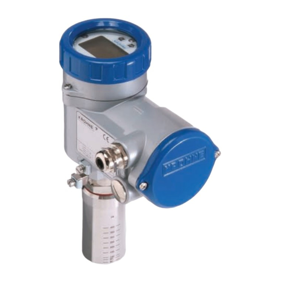
DWM 2000 D
Operating instructions
DWM 2000 Electromagnetic Flowmeter with LCD Indicator
Related Manuals for KROHNE DWM 2000 D
Summary of Contents for KROHNE DWM 2000 D
-
Page 1
DWM 2000 D Operating instructions DWM 2000 Electromagnetic Flowmeter with LCD Indicator… -
Page 2: Table Of Contents
Contents Display data in operating mode…………………………………………………………………..3 Functions of the LCD indicator for the DWM 2000 D ………………………………………..4 Programmable parameters ………………………………………………………………………..4 2.1.1 Flow calibration ………………………………………………………………………4 2.1.2 Current output adjustment ………………………………………………………….4 2.1.3 Time constant ………………………………………………………………………..4 …
-
Page 3: Display Data In Operating Mode
Display data in operating mode Operating Instructions DWM 2000 D…
-
Page 4: Functions Of The Lcd Indicator For The Dwm 2000 D
Functions of the LCD indicator for the DWM 2000 D Programmable parameters 2.1.1 Flow calibration The G can be modified in menu 2.1.3 in order to obtain the maximum accuracy at operating conditions. A field calibration requires an accurate reference of velocity. The meter recalibration (G modification) is also recommended after an exchange of electronics module.
-
Page 5: Electronics Module Checks
Make sure that the instrument is correctly grounded. Install the instrument in the sequence given in the installation manual. A bad mechanical or electrical connection will cause the DWM 2000 to operate incorrectly. Programming structure (Software n° 1.02) 2.3.1 User interface buttons Operating Instructions DWM 2000 D…
-
Page 6: Menu Naviagation
2.3.2 Menu navigation Go through the steps given in the illustrations that follow to get to the required menu. Operating Instructions DWM 2000 D…
-
Page 7
Operating Instructions DWM 2000 D… -
Page 8: Summary Of Programming Menus
Primary head calibration constant 0.8 ≤ G ≤ 1.300 2.1.3. GK VALUE See section “1.1.1. Flow calibration” on how to recalculate G 2.1.4. CORRECTION Activation of the low flow linearization for velocity below 3 m/s. Select “YES” or “NO”, default setting:“YES” Operating Instructions DWM 2000 D…
-
Page 9
“0” and switch off the flow rate line on the indicator display. Use menu 2.4.3 to read EEPROM settings (this includes DIAMETER). If the value is reset to “0”, you must re-enter the pipe diameter in menu 2.4.6. Operating Instructions DWM 2000 D… -
Page 10: Parameters Stored In The Eeprom (Menu 2.4.3)
Test value of the amplifier control 75 … 95 loop (see menu 1.1.4.) Frequency of the magnetic field 10 … 14.5 Hz (see menu 1.1.1.) ≥ 50 mm DIAMETER Diameter of pipeline (see menu 2.4.6) Operating Instructions DWM 2000 D…
-
Page 11: Error Message List
FS SWIT EEP Modification of the full scale power on Program the full scale power off ZERO Velocity measurement during the zero Deactivate the alarm mode and adjustment is more than 0.2 m/s. adjust the zero again Operating Instructions DWM 2000 D…
-
Page 12
DWM 2000 D nnnnnnnnnnnnnnnnnnnnnnnnnnnnnnnnnnnnnnnnnnn KROHNE measuring technology — Product overview • • Electromagnetic flowmeters Level measuring instruments • • Variable area flowmeters Temperature measuring instruments • • Mass flowmeters Pressure measuring instruments • • Ultrasonic flowmeters Analysis • • Vortex flowmeters Oil and gas industry •…

2
Содержание
Страница
Общее
……………………………………………………………………… 3
Специальное
исполнение
Принцип
измерения
Компоненты
Установка
……………………………………………………………….. 6
Установка
на
трубопроводе
Габариты
и
Вес
Электрические
соединения
и
установочные
параметры
DWM1000…………………………………………………………….. 8
DWM2000…………………………………………………………….. 8
Совместимость
реле
(
для
DWM1000)………………………. 15
Информация
для
зоны
2 ………………………………………… 15
Версия
DWM 2000 IP68 …………………………………………… 16
Версия
DWM2000 L (
длинная
)
Характеристики
……………………………………………………. 18
Компоненты
…………………………………………………………. 19
Установка
…………………………………………………………….. 20
Возможные
неисправности
…………………………………….. 23
Технические
характеристики
…………………………………. 25
Контактные
адреса
фирмы
KROHNE ……………………… 28

KROHNE
10/99
Электромагнитный
Индикатор потока и
Расходомер
Инструкция
по установке и
эксплуатации
DWM
1000
DWM
2000
DWM 2000 L
DWM 2000 IP68
KROHNE S.A
сертифицирована
ISO 9001

 DWM 2000 D Operating instructions
DWM 2000 Electromagnetic Flowmeter with LCD Indicator
Contents
1 Display data in operating mode…………………………………………………………………..3
2 Functions of the LCD indicator for the DWM 2000 D ………………………………………..4
2.1Programmable parameters ………………………………………………………………………..4
2.1.1Flow calibration ………………………………………………………………………4
2.1.2Current output adjustment ………………………………………………………….4
2.1.3Time constant ………………………………………………………………………..4
2.2 Electronics module checks ……………………………………………………………………..5
2.3Programming structure (Software n° 1.02) ………………………………………………………5
2.3.1User interface buttons ………………………………………………………………5
2.3.2Menu naviagation ……………………………………………………………………6
2.3.3Summary of programming menus …………………………………………………8
2.4Parameters stored in the EEPROM (menu 2.4.3) …………………………………………….10
2.5Error message list ………………………………………………………………………………..11
|
2 |
Operating Instructions DWM 2000 D |
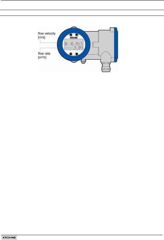
1 Display data in operating mode
|
Operating Instructions DWM 2000 D |
3 |

2 Functions of the LCD indicator for the DWM 2000 D
2.1Programmable parameters
2.1.1 Flow calibration
The GK can be modified in menu 2.1.3 in order to obtain the maximum accuracy at operating conditions. A field calibration requires an accurate reference of velocity. The meter recalibration (GK modification) is also recommended after an exchange of electronics module.
The value of the new calibration constant (GK new) can be calculated as follows:
GKnew = GKold x Va
Vm
with:
Va = actual velocity
Vm = measured velocity (reference value)
2.1.2 Current output adjustment
The minimum value (i0%) and the maximum value (i100%) of the current output at normal operating conditions can be adjusted from menus 2.2.2. and 2.2.3.
The actual values of the i0% and the i100% must be measured with an accurate milliammeter in a 4…20 mA loop.
i0% must be in the range 3….12 mA. The factory setting is 4 mA. i100% must be in the range 12….21 mA. The factory setting is 20 mA.
2.1.3 Time constant
The time constant value can be set in menu 2.2.4. This value represents the time needed to detect 63% of a simulated flow rate instantaneously raised from 0 to 100%. Time constant range : 5, 10, 15, 20, 25, 30, 50 m.
|
4 |
Operating Instructions DWM 2000 D |
 Loading…