-
Contents
-
Table of Contents
-
Bookmarks
Quick Links
DVPEN01-SL
Ethernet Communication Module
Operation Manual
DVP-0204320-04
Related Manuals for Delta DVPEN01-SL
Summary of Contents for Delta DVPEN01-SL
-
Page 1
DVPEN01-SL Ethernet Communication Module Operation Manual DVP-0204320-04… -
Page 3: Table Of Contents
LED Indicators …………………….. 4 RJ-45 PIN Definition ……………………. 5 INSTALLATION & WIRING …………………… 5 Installation ……………………..5 Connecting DVPEN01-SL to the Network: …………….6 CONTROL REGISTER (CR) ………………….6 Control Registers in DVPEN01-SL ………………. 6 Explanations on CR ……………………8 Numbering of Left-Side Modules ………………..
-
Page 4
APPLICATION EXAMPLES ………………….34 Setting an IP Address and Communication through WPLSoft ……….34 Connecting the PC with DVPEN01-SL through LAN …………… 36 Setting a Password and Clearing a Password ……………. 38 When the Password is Lost (Returning to Default Setting by RS-232) ……..41 IP Filter Protection …………………… -
Page 5: Introduction
DVPEN01-SL is an Ethernet communication module for remote setting and communication through WPLSoft. DVPEN01-SL is able to send E-mails, automatically correct the RTC in DVP28SV11R/T and exchange data. It supports MODBUS TCP communication protocol and can conduct remote monitoring by using SCADA (Supervisor Control and Data Acquisition) software or HMI (Human Machine Interfaces).
-
Page 6: Product Profile & Outline
Ethernet Communication Module DVPEN01-SL Electrical specifications Item Specification Power supply voltage 24VDC (-15%~20%) (Power is supplied by the internal bus of MPU.) Power consumption 1.5W Insulation voltage 500V Weight (g) 92 (g) Product Profile & Outline 2.1 Dimension 3 [0.118]…
-
Page 7: Pin Definition
DVP28SV POWER RS-232 100M LINK RS-232 Connecting DVPEN01-SL to other I/O modules: To connect DVPEN01-SL with the other I/O module, lift the extension clip of the I/O module by a screwdriver and open the side cover. DVP-PLC Operation Manual…
-
Page 8: Connecting Dvpen01-Sl To The Network
Ethernet Communication Module DVPEN01-SL 3.2 Connecting DVPEN01-SL to the Network: Connect DVPEN01-SL to the Ethernet Hub by twisted pair cable CAT-5e. DVPEN01-SL has Auto MDI/MDIX function; therefore, DVPEN01-SL does not need to use a crossing cable between the PC and DVPEN01-SL.
-
Page 9
Ethernet Communication Module DVPEN01-SL Attribute Content Explanation Data exchange cycle The control register is used to set data exchange cycle time. The time unit used is a millsecond. 0: No error occurs. Error status of slaves in 1: An error occurs in data exchange. -
Page 10: Explanations On Cr
You can read the model code in the program to see if the I/O module exists. CR #1: Firmware version Explanations: The firmware version of DVPEN01-SL is displayed in hex, e.g. H’0100 indicates version V1.00. CR #2: Communication mode Explanations: Bit No.
-
Page 11
Ethernet Communication Module DVPEN01-SL CR #9 ~ 1 2: E-mail 1~4 additional message Explanations: The user fills in the code, and the code will be stored in the title of the E-mail and sent out with the E-mail. Data Exchange … -
Page 12
Explanations: When you set the Salve ID (i.e. K1~K255) for data exchange, DVPEN01-SL will automatically search for the corresponding IP address from the slave IP address list. For example, if the ID is set as “0”, the value in CR#25 and #26 will be regarded as the destination IP address. -
Page 13
D8~D11 of the Master will be written into D2~D5 of the Slave. Both sending and receiving can be executed at the same time. When the values in CR#82 and #85 are both “0”, DVPEN01-SL will use the default registers DVP-PLC Operation Manual… -
Page 14
Ethernet Communication Module DVPEN01-SL (CR#29~CR#68) and number of registers (K20). Setting an IP address CR #8 7: Mode of setting an IP address Explanations: 0: Static IP address 1: DHCP CR #8 8 ~ 89 : IP address Explanations: The control registers are used to set an IP address. -
Page 15
CR#112 is the TCP Keepalive timeout for MODBUS TCP connection. (Unit: Second) Default: 30s If the connection idle time becomes longer than the keep-alive time-out, DVPEN01-SL will cut off the idle connection. CR # 11 4: MODBUS TCP timeout Explanations:… -
Page 16: Numbering Of Left-Side Modules
4.3 Numbering of Left-Side Modules After DVPEN01-SL is installed properly, you need to compile the PLC program to control the special I/O module. PLC offers FROM instruction (for reading) and TO instruction (for writing) to control the control registers (CR) in the special I/O module.
-
Page 17: Setting The Software
Ethernet in the Communication Setting window. Next, you can search by IP address or use Auto-Search. You also can open the setup page for DVPEN01-SL by RS-232. DVPEN01-SL is set by UDP port 20006;…
-
Page 18
1. Click Search in DCISoft to search for all Delta Ethernet products on the network. The window on the left hand side shows the models found, and the window on the right hand side displays the device list of all models. -
Page 19
Ethernet Communication Module DVPEN01-SL 3. You will see the basic setup page as follow. Designating a model to search 1. Right click Ethernet on the left hand side window and click Configure to designate a model to search for. -
Page 20
Ethernet Communication Module DVPEN01-SL 2. After configure a model, select the DVPEN01-SL checkbox and click OK to auto-search for DVPEN01-SL modules on the network. 3. List of the current DVPEN01-SL modules DVP-PLC Operation Manual… -
Page 21
Ethernet Communication Module DVPEN01-SL Searching by an IP address 1. Select Ethernet in the Communication Type section, and enter the IP address. Click OK. 2. Click IP Search to start searching for the designated IP address. DVP-PLC Operation Manual… -
Page 22
Ethernet Communication Module DVPEN01-SL 3. The DVPEN01-SL module found will be displayed in the right hand side window. Double click it to enter the setup page. Opening the DVPEN01-SL setup page by RS-232 1. Select RS232 as the transmission type in the Communication Setting window. You will have to designate a communication port. -
Page 23: Basic Settings
Basic settings 1. Module Name There can be many DVPEN01-SL modules in the network. Thus, you can set a module name for each module to identify the module when you need to use them. 2. Module Language You can select a language for each module name, and the windows will be displayed in the selected language.
-
Page 24: Network Settings
You should choice the Time zone that you are. 8. Protocol Select DVPEN01-SL supports MODBUS TCP and the Mitsubishi MELSEC protocol in a UDP mode. The defatul setting is MODBUS TCP. 5.3 Network Settings The first step for all the network equipment to connect to the network is to have its own IP address (Internet Protocol).
-
Page 25
Ethernet Communication Module DVPEN01-SL 2. You will see the Local Area Connection Status window. Click on Properties. 3. Click on Internet Protocol (TCP/IP). 4. Enter 192.168.0.1 into the IP address box. Click on OK to complete the IP address setting of the PC. -
Page 26
For example, if the LAN has to be connected to WAN, it will need a gateway to bridge the communication. The IP address of the gateway has to be in the same subnet as DVPEN01-SL. The default gateway IP address of DVPEN01-SL is 192.168.1.1. -
Page 27: Setting E-Mails
DVPEN01-SL offers 4 sets of E-mail information, and you can self-define the register or bit information to be read. When the trigger occurs, DVPEN01-SL will add the set register or bit present value read to the E-mail. Every piece of E-mail information is able to contain the present values in the up to 100 consecutive registers.
-
Page 28: Snmp
SMTP server first, and the server will further send the mail to the designated address. 5.5 SNMP SNMP is a simple network management function. Users can read and control the registers in a PLC by means of a SNMP network management tool. (DVPEN01-SL version 2.06 and above support this function.) Setting …
-
Page 29: Data Exchange
3. Station Address and IP Address You have to enter the IP address of DVPEN01-SL at the other end. For example, if you would like DVPEN01-SL to exchange data with 192.168.0.1, set No. 1 as 192.168.0.1. When the data are being exchanged, if the value in CR#28 is H’0001, the data will be exchanged with 192.168.0.1.
-
Page 30: Melsec Protocol
Ethernet Communication Module DVPEN01-SL MELSEC Protocol DVPEN01-SL can communicate with Mitsubishi devices by means of the MELSEC protocol. It can support the communication with a master and the communication with slaves simultaneously. Only UDP communication is allowed. (DVPEN01-SL version 2.10 and above support this function.) Setting the MELSEC protocol mode …
-
Page 31
For example, the users can type the slave ID 1 and the IP address 192.168.0.1. If data exchange is executed, DVPEN01-SL will exchange data with the device whose slave ID is 1 and whose IP address is 192.168.0.1 by means of the MELSEC communication. -
Page 32: Rtu
Use the RTU function to conduct mapping between Delta’s network modules DVPEN01-SL and RTU-EN01.Set the mapping information first, and you will be able to use WPLSoft in DVPEN01-SL to save and retrieve the mapped bit (M) and register (D) in order to operate the remote RTU-EN01.
-
Page 33: Ip Filter
Ethernet Communication Module DVPEN01-SL 5.9 IP Filter An IP filter is used for restricting the connection of the network in case some uncertain IP addresses will cause errors. Only the IP addresses set within a certain range can establish a connection. Other IP addresses will be rejected.
-
Page 34: Setting A Password
Incorrect settings may result in connection failure. Therefore, DO NOT set the MAC address of the equipment without the network into the table. 5.11 Setting a Password To prevent the set values in DVPEN01-SL from being modified, you can set a password to lock the settings in DVPEN01-SL. Setting the DVPEN01-SL password …
-
Page 35: Returning To Default Settings
Note: If you set DVPEN01-SL by RS-232, you can return the setting to default setting whether the password is locked or not. It takes approximately 10 seconds to return to default setting, so DO NOT switch off the power within the 10 seconds.
-
Page 36: Application Examples
(3) IP address of DVPEN01-SL: 192.168.0.4 (4) Connect the PC and DVPEN01-SL by RJ-45 cable. Note: Both PC and DVPEN01-SL have to adopt a static IP address. 1. The connection 2. Start WPLSoft, and click Ethernet in the Communication Setting Section.
-
Page 37
Ethernet Communication Module DVPEN01-SL 4. All the devices connected to the network are shown in the Ethernet section. After DELTA DVPEN01-SL is clicked, WPSoft can communicate with the MPU by means of DVPEN01-SL. 5. After DELTA DVPEN01-SL in the Ethernet section is double-clicked, DCISoft will be started. Please refer to section 5.3 for more infomrationa bout setting an IP address. -
Page 38: Connecting The Pc With Dvpen01-Sl Through Lan
Application Setting the network parameters of DVPEN01-SL by WPLSoft through LAN. Network (1) Connect the PC and DVPEN01-SL by using DHCP server through LAN. environment (2) IP address of DVPEN01-SL: 172.16.157.148 Note: DVPEN01-SL can use a RJ-45 cable with/without a jump wire.
-
Page 39
3. Click Auto-Search Ethernet Module to search for all the Ethernet modules on the network. 4. All the devices connected to the network are shown in the Ethernet section. After DELTA DVPEN01-SL is clicked, WPSoft can communicate with the MPU by means of DVPEN01-SL. -
Page 40: Setting A Password And Clearing A Password
Ethernet Communication Module DVPEN01-SL 5. After DELTA DVPEN01-SL in the Ethernet section is double-clicked, DCISoft will be started. Please refer to section 5.3 for more infomrationa bout setting an IP address. 6. After the setting of an IP address is complete, and step 2~step 4 are repeated, the IP address can be used for communication.
-
Page 41
Ethernet Communication Module DVPEN01-SL 3. Select the Modify checkbox, and enter “aabb” in the Password box and the Confirm Password box. Click on OK to save the password. DVP-PLC Operation Manual… -
Page 42
Ethernet Communication Module DVPEN01-SL 4. Open the setup page again, and DVPEN01-SL is now locked by the password. You cannot open any of the settings now. Click on Confirm to leave the entering password window. 5. Enter the password to temporarily unlock the protection and modify the parameters. If you close the setup page, the locking will automatically be recovered. -
Page 43: When The Password Is Lost (Returning To Default Setting By Rs-232)
Returning to default setting by RS-232 Network (1) DVPEN01-SL is set with a password. environment (2) The password is forgotten. 1. Use DVPACAB2A30 cable to connect the PC and DVPEN01-SL and open the setup page. Open the Security page. DVP-PLC Operation Manual…
-
Page 44: Ip Filter Protection
6.5 IP Filter Protection Application Setting the IP filter protection Network (1) IP address of DVPEN01-SL: 192.168.0.4 environment (2) Only connections to 192.168.0.7 and 172.16.0.1~172.16.0.255 are allowed. 1. See 6.1 for the connection and how to set the communication. 2. Open the setup page and switch to the IP Filter page.
-
Page 45
Ethernet Communication Module DVPEN01-SL 3. Select the Enable IP Filter checkbox. Enter “192.168.0.4” in the No. 1 IP Address box and “255.255.255.255” in the No. 1 Subnet Netmask box. 4. Enter “192.168.0.1” in the No. 2 IP Address box and “255.255.255.0” in the No.2 Subnet Netmask box. Click on OK to complete the setting. -
Page 46: Setting A Static Arp Table
Ethernet Communication Module DVPEN01-SL 6.6 Setting a Static ARP Table Application Setting a static ARP table Network (1) MAC address of equipment 192.168.1.6 is 00:18:23:10:00:35 environment (2) MAC address of equipment 192.168.1.1 is 00:18:23:10:00:04 1. See 6.1 for the connection and how to set the communication.
-
Page 47
Only the equipment within the IP address range can be connected. Note: The MAC address of DVPEN01-SL can be obtained from WPLSoft or the MAC address sticker on the equipment. The MAC address of PC can be found in the Network Connection Details widow (see below). -
Page 48: Application Of E-Mails
Ethernet Communication Module DVPEN01-SL 6.7 Application of E-mails Application Sending an E-mail to notify the administrator when the current status of X0 and Y0 is changed. Network (1) IP address of the SMTP server: 172.16.144.121 application (2) E-mail address of administrator: test@sample.com (3) An E-mail message will be generated when the status of X0 and Y0 is changed.
-
Page 49: Application Of Data Exchange (1)
K100 Explanations: • If the rising-edge of X0 is triggered, X0 will go from Off to On. Write “1” into CR#3 of DVPEN01-SL, and the first E-mail will be sent out. • If the falling-edge of X0 is triggered, X0 will go from On to Off. Write “1” into CR#4 of DVPEN01-SL, and the second E-mail will be sent out.
-
Page 50
Ethernet Communication Module DVPEN01-SL 2. Open the setup page of PLC_B and switch to the Data Exchange page. 3. Select the Enable Data Exchange checkbox. Select Program Control in the Enable Confition drop-down list box. Enter the IP address of PLC_A “192.168.0.4” in the IP Address cell corresponding to station address 1. -
Page 51: Application Of Data Exchange (2)
• The data exchange will be executed every one second. • Write the communication address of the destination PLC in CR#28, and DVPEN01-SL will automatically detect by the previous setting that No. 1 IP address is “192.168.0.4″. • Write the data in RTC into CR#29~CR#35.
-
Page 52
Ethernet Communication Module DVPEN01-SL (1) Adopt a static IP address. (2) IP address of PLC_A: 192.168.1.99 Network environment (3) IP address of PLC_B: 192.168.1.97 (4) Update from PLC_A to PLC_B and PLC_B to PLC_A. 1. See 6.1 for how to set the communication. -
Page 53: Application Of Data Exchange (3)
Ethernet Communication Module DVPEN01-SL 6.10 Application of Data Exchange (3) Firmware version 2.0 and above support this function. Enable a timer (X20) and write the timer values into D0~D99. Control the program (X21) and write the Application present values in D0~D99 of PLC_A into D0~D99 of PLC_B, and write the values in D0~D99 of PLC-B into D200~D299 of PLC_A.
-
Page 54: Application Of Data Exchange (4)
Ethernet Communication Module DVPEN01-SL 4. After all the settings in PLC_A are completed, you have to write a ladder diagram for the MPU and download it to PLC_B. The program designed is like the one shown below. 6.11 Application of Data Exchange (4)
-
Page 55
Ethernet Communication Module DVPEN01-SL M1000 D100 M1013 K100 K100 HC0A8 K100 K100 D100 K100 K100 FROM K100 = D14 K2 = D14 K3 Explanations: • The data exchange will be executed every one second. • Write “0” into CR#28, and PLC_B will use CR#25~CR#26 as the IP address of the destination PLC. -
Page 56: Application Of Data Exchange (5)
Ethernet Communication Module DVPEN01-SL 6.12 Application of Data Exchange (5) Writing the time in RTC in PLC_B directly into D0~D6 of PLC_A without writing in ladder diagram into Application PLC_A. Network (1) Adopt a static IP address. environment (2) IP addres of PLC_A: 192.168.0.4 (3) IP address of PLC_B: 192.168.0.5…
-
Page 57: Application Of Modbus Tcp Master
Ethernet Communication Module DVPEN01-SL • Write the IP address of PLC_A into CR#25 and CR#26. The first two IP codes (192.168=H’C0A8) should be written into CR#26, and the last two IP codes (0.4=H’0004) into CR#25. • Write the MODBUS address of D0 (H’1000) in PLC_A into CR#81 and CR#84.
-
Page 58: Rtu Mapping
(5) Set the mapping start address and number of data for RX, RY, RCR (read) and RCR (write) at DVPEN01-SL. (6) Enable the mapping function in DVP-SV PLC at DVPEN01-SL. Use M2000 and D2000 in DVP-SV to read and M3000 and D3000 to write the value in the remote RTU-EN01.
-
Page 59
3. Use DCISoft for DVPEN01-SL to set start addresses and numbers. (RX: M2000~M2009; RY: M3000~M3009; RCR (Reading): D2000~D2009; RCR (Writing): D3000~D3009) 4. Edit a ladder diagram, and download it to DVPEN01-SL. The program edited is like the one shown below. DVP-PLC Operation Manual… -
Page 60: Application Of The Melsec Protocol
Communication port: 9002 3. Write a program for the MPU, and download it to DVPEN01-SL. The program designed is like the one shown below. 4. Use DCISof to set data exchange for DVPEN01-SL. ※ After the settings are downloaded, DVPEN01-SL will read the data in D0~D99 in the Mitsubish PLC into D0~D99 in DVP28SV, and write the data in D100~D199 in DVP28SV into D100~D199 in the Mitsubish PLC.
![]()
DVPEN01-SL
Ethernet Communication Module
Operation Manual
DVP-0204320-02

Ethernet Communication Module DVPEN01-SL
Warning
3Please read this instruction carefully before use and follow this instruction to operate the device in order to prevent damages on the device or injuries to staff.
3Switch off the power before wiring.
3RTU-DNET is an OPEN TYPE device and therefore should be installed in an enclosure free of airborne dust, humidity, electric shock and vibration. The enclosure should prevent non-maintenance staff from operating the device (e.g. key or specific tools are required for operating the enclosure) in case danger and damage on the device may occur.
3RTU-DNET is to be used for controlling the operating machine and equipment. In order not to damage it, only qualified professional staff familiar with the structure and operation of RTU-DNET can install, operate, wire and maintain it.
3DO NOT connect input AC power supply to any of the I/O terminals; otherwise serious damage may occur. Check all the wirings again before switching on the power and DO NOT touch any terminal when the power is switched on. Make sure the ground terminal  is correctly grounded in order to prevent electromagnetic interference.
Table of Contents
|
1 |
INTRODUCTION………………………………………………………………………………………………………………….. |
3 |
|
|
1.1 |
Functions……………………………………………………………………………………………………………………. |
3 |
|
|
1.2 |
Specifications ……………………………………………………………………………………………………………… |
3 |
|
|
2 |
PRODUCT PROFILE & OUTLINE …………………………………………………………………………………………. |
4 |
|
|
2.1 |
Dimension ………………………………………………………………………………………………………………….. |
4 |
|
|
2.2 |
Product Profiles…………………………………………………………………………………………………………… |
4 |
|
|
2.3 |
LED Indicators…………………………………………………………………………………………………………….. |
5 |
|
|
2.4 |
RJ-45 PIN Definition…………………………………………………………………………………………………….. |
5 |
|
|
3 |
INSTALLATION & WIRING …………………………………………………………………………………………………… |
5 |
|
|
3.1 |
Installation ………………………………………………………………………………………………………………….. |
5 |
|
|
4 |
CONTROL REGISTER (CR) …………………………………………………………………………………………………. |
6 |
|
|
4.1 |
Control Registers in DVPEN01-SL…………………………………………………………………………………. |
6 |
|
|
4.2 |
Explanations on CR …………………………………………………………………………………………………….. |
8 |
|
|
4.3 |
Numbering of Left-Side Modules………………………………………………………………………………….. |
13 |
|
|
5 |
SETTING UP SOFTWARE ………………………………………………………………………………………………….. |
14 |
|
|
5.1 |
Setting up Communication & Searching for Modules………………………………………………………. |
14 |
|
|
5.2 |
Basic Settings …………………………………………………………………………………………………………… |
20 |
|
|
5.3 |
Network Settings ……………………………………………………………………………………………………….. |
21 |
|
|
5.4 |
Setting up E-Mails ……………………………………………………………………………………………………… |
24 |
|
|
5.5 |
Data Exchange………………………………………………………………………………………………………….. |
25 |
|
|
5.6 |
RTU …………………………………………………………………………………………………………………………. |
26 |
|
|
5.7 |
IP Filter…………………………………………………………………………………………………………………….. |
27 |
|
|
5.8 |
Static ARP Table………………………………………………………………………………………………………… |
27 |
|
|
5.9 |
Setting up Password ………………………………………………………………………………………………….. |
28 |
|
DVP-PLC Operation Manual |
1 |

|
Ethernet Communication Module DVPEN01-SL |
||
|
5.10 |
Returning to Default Setting ……………………………………………………………………………………….. |
29 |
|
6 APPLICATION EXAMPLES………………………………………………………………………………………………… |
30 |
|
|
6.1 |
Setting up IP and Communicating through WPLSoft………………………………………………………. |
30 |
|
6.2 |
Connecting the PC with DVPEN01-SL through LAN ………………………………………………………. |
33 |
|
6.3 |
Setting up Password and Clearing Password ……………………………………………………………….. |
37 |
|
6.4 |
When the Password is Lost (Returning to Default Setting by RS-232)………………………………. |
39 |
|
6.5 |
IP Filter Protection …………………………………………………………………………………………………….. |
40 |
|
6.6 |
Setting up Static ARP Table ………………………………………………………………………………………… |
42 |
|
6.7 |
Application of E-Mail………………………………………………………………………………………………….. |
44 |
|
6.8 |
Application of Data Exchange (1) ………………………………………………………………………………… |
45 |
|
6.9 |
Application of Data Exchange (2) ………………………………………………………………………………… |
48 |
|
6.10 |
Application of Data Exchange (3) ………………………………………………………………………………… |
49 |
|
6.11 |
Application of Data Exchange (4) ………………………………………………………………………………… |
50 |
|
6.12 |
Application of Data Exchange (5) ………………………………………………………………………………… |
52 |
|
6.13 |
Application of Modbus TCP Master ……………………………………………………………………………… |
53 |
|
6.14 |
RTU Mapping……………………………………………………………………………………………………………. |
54 |
|
2 |
DVP-PLC Operation Manual |

Ethernet Communication Module DVPEN01-SL
1 Introduction
Thank you for choosing DVPEN01-SL module. To correctly install and operate DVPEN01-SL, please read the manual carefully before using the module.
DVPEN01-SL is an Ethernet communication module for remote setting and communication through WPLSoft. DVPEN01-SL is able to send E-mails, automatically correct the RTC in DVP28SV11R/T and exchange data. It supports Modbus TCP communication protocol and can conduct remote monitoring by using SCADA (Supervisor Control and Data Acquisition) software or HMI (Human Machine Interfaces). DVPEN01-SL can be the master of Modbus TCP, sending out Modbus TCP instructions and controlling the peripheral equipment. In addition, under MDI/MDI-X auto-detection, it does not need to use a crossing cable. See the contents below for more detailed instructions on DVPEN01-SL module.
1.1Functions
zAuto-detects 10/100Mbps transmission speed
zMDI/MDI-X auto-detection
zSupports Modbus TCP protocol (at the same time supports Master and Slave mode)
zAble to send out E-mails
zAuto-corrects the RTC in PLC through the Internet time correction function
zSupports point-to-point data exchange (Max. data exchange length: 200 bytes)
1.2Specifications
Internet interface
|
Item |
Specification |
|
Interface |
RJ-45 with Auto MDI/MDIX |
|
Number of ports |
1 Port |
|
Transmission method |
IEEE802.3, IEEE802.3u |
|
Transmission cable |
Category 5e |
|
Transmission speed |
10/100 Mbps Auto-Detect |
|
Network protocol |
ICMP, IP, TCP, UDP, DHCP, SMTP, NTP, Modbus TCP |
|
Serial communication interface |
|
|
Item |
Specification |
|
Interface |
RS-232 |
|
Number of ports |
1 Port |
|
Transmission cable |
DVPACAB230, DVPACAB215, DVPACAB2A30, DVPACAB2B10 |
|
Environment |
|
|
Specification |
|
|
Item |
|
|
ESD (IEC 61131-2, IEC 61000-4-2): 8KV Air Discharge |
|
|
EFT (IEC 61131-2, IEC 61000-4-4): Power Line: 2KV |
|
|
Noise immunity |
Analog & Communication I/O: 1KV |
|
Damped-Oscillatory Wave: Power Line: 1KV |
|
|
RS (IEC 61131-2, IEC 61000-4-3): 26MHz ~ 1GHz, 10V/m |
|
|
Environment |
Operation: 0°C ~ 55°C (temperature), 50 ~ 95% (humidity), Pollution degree 2; |
|
DVP-PLC Operation Manual |
3 |
Ethernet Communication Module DVPEN01-SL
|
Item |
Specification |
|
Storage: -25°C ~ 70°C (temperature), 5 ~ 95% (humidity) |
|
|
Vibration/ Shock Resistance |
Standard: IEC61131-2, IEC 68-2-6 (TEST Fc)/IEC61131-2 & IEC 68-2-27 (TEST Ea) |
|
Electrical specifications |
|
|
Item |
Specification |
|
Power supply voltage |
24VDC (-15% ~ 20%) (Power is supplied by the internal bus of MPU.) |
|
Power consumption |
1.5W |
|
Insulation voltage |
500V |
|
Weight (g) |
92 (g) |
2Product Profile & Outline
2.1Dimension
3 [0.118]
DVPEN01
POWER
RS-232
100M
LINK
RS-232 [3.543]
90
LAN
Unit: mm [inches]
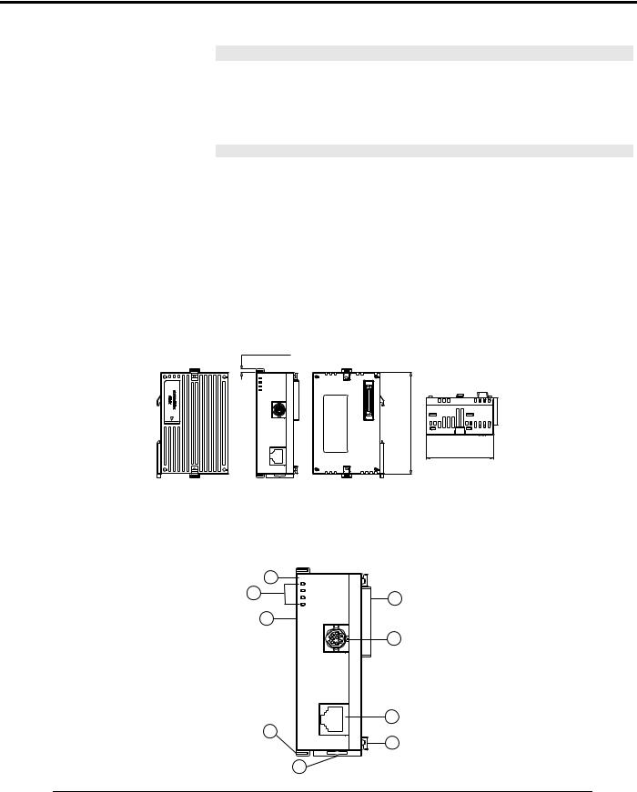
2.2Product Profiles
|
1 |
DVPEN01 |
|
|
POWER |
||
|
4 |
RS-232 |
2 |
|
100M |
||
|
LINK |
3
8
RS-232
|
7 |
9 |
|
|
LAN |
6 |
|
|
5 |
60 [2.362]
|
1. |
Model name |
6. |
Fixing tenon for I/O module |
|||
|
2. |
Extension port to connect device |
7. |
Fixing clip for I/O module |
|||
|
3. |
Extension port to connect I/O module |
8. |
RS-232 connection port |
|||
|
4. |
POWER, LINK, RS-232, 100M indicators |
9. |
Ethernet RJ-485 connection port |
|||
|
5. |
DIN rail clip |
|||||
|
4 |
DVP-PLC Operation Manual |
Ethernet Communication Module DVPEN01-SL
2.3LED Indicators
|
Indicator |
Color |
Indication |
|
POWER |
Green |
Power indication |
|
RS-232 |
Red |
Communication status of the series port |
|
100M |
Orange |
Network connection status |
|
LINK |
Green |
Network communication speed |
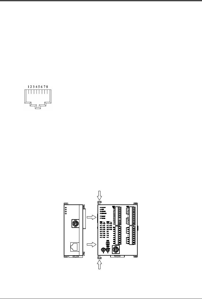
2.4RJ-45 PIN Definition
|
RJ-45 sketch |
Terminal No. |
Definition |
Explanation |
|
1 |
Tx+ |
Positive pole for data transmission |
|
|
2 |
Tx- |
Negative pole for data transmission |
|
|
3 |
Rx+ |
Positive pole for data receiving |
|
|
6 |
Rx- |
Negative pole for data receiving |
|
|
4, 5, 7, 8 |
— |
N/C |
|
3 Installation & Wiring
This section gives instructions on how to connect DVPEN01-SL with PLC MPU and how to connect DVPEN01-SL to the network.
3.1Installation
Connect PLC MPU to DVPEN01-SL
zAdjust the I/O module clip on the left side of the MPU.
zMeet the I/O module port of the MPU with DVPEN01-SL as shown in the figure below.
zFasten the I/O module clip on the left side of the MPU.
|
DVPEN01 |
DVP28SV |
|
POWER |
|
|
RS-232 |
|
|
100M |
|
|
LINK |
|
|
RS-232 |
LAN
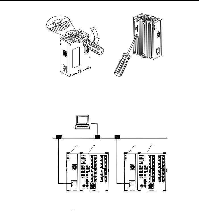
Connect DVPEN01-SL to other I/O modules
zTo connect DVPEN01-SL with the other I/O module, lift the extension clip of the I/O module by a screwdriver and open the side cover.
|
DVP-PLC Operation Manual |
5 |
Ethernet Communication Module DVPEN01-SL
Connect DVPEN01-SL to the Network:
Connect DVPEN01-SL to the Ethernet Hub by twisted pair cable CAT-5e. DVPEN01-SL has Auto MDI/MDIX function; therefore, DVPEN01-SL does not need to use a crossing cable between the PC and DVPEN01-SL. Network connections between the PC and DVPEN01-SL:
PC Master
|
Ethernet |
|||
|
DVPEN01 DVP28SV |
DVPEN01 DVP28SV |
||
|
DVPEN01 |
DVP28SV |
DVPEN01 |
DVP28SV |
|
POWER |
POWER |
||
|
RS-232 |
RS-232 |
||
|
100M |
100M |
||
|
LINK |
LINK |
||
|
RS-232 |
RS-232 |
4Control Register (CR)
4.1Control Registers in DVPEN01-SL
|
CR# |
Attribute |
Content |
Explanation |
|||
|
HW |
LW |
|||||
|
#0 |
R |
Model name |
Set up by the system; read only. Model code of DVPEN01-SL |
|||
|
= H’4050 |
||||||
|
#1 |
R |
Firmware version |
Displaying the current firmware version in hex. |
|||
|
#2 |
R |
Communication mode |
b0: Modbus TCP mode; b1: data exchange mode |
|||
|
#3 |
W |
E-Mail Event 1 trigger |
Set up whether to send E-Mail 1 |
|||
|
#4 |
W |
E-Mail Event 2 trigger |
Set up whether to send E-Mail 2 |
|||
|
#5 |
W |
E-Mail Event 3 trigger |
Set up whether to send E-Mail 3 |
|||
|
#6 |
W |
E-Mail Event 4 trigger |
Set up whether to send E-Mail 4 |
|||
|
6 |
DVP-PLC Operation Manual |

Ethernet Communication Module DVPEN01-SL
|
CR# |
Attribute |
Content |
Explanation |
||
|
HW |
LW |
||||
|
#7 |
R |
Status of E-Mail 1, 2 |
b0 ~ b7: Current status of E-Mail 2 |
||
|
b8 ~ b15: Current status of E-Mail 1 |
|||||
|
#8 |
R |
Status of E-Mail 3, 4 |
b0 ~ b7: Current status of E-Mail 4 |
||
|
b8 ~ b15: Current status of E-Mail 3 |
|||||
|
#9 |
R/W |
E-Mail 1 additional |
Filled in by the user, and it will be send by E-mail. |
||
|
message |
|||||
|
#10 |
R/W |
E-Mail 2 additional |
Filled in by the user, and it will be send by E-mail. |
||
|
message |
|||||
|
#11 |
R/W |
E-Mail 3 additional |
Filled in by the user, and it will be send by E-mail. |
||
|
message |
|||||
|
#12 |
R/W |
E-Mail 4 additional |
Filled in by the user, and it will be send by E-mail. |
||
|
message |
|||||
|
#13 |
R/W |
Data exchange trigger |
Set up whether to send out data in data exchange mode |
||
|
#14 |
R |
Status of data exchange |
Displaying current status of data exchange. |
||
|
#15 |
RW |
Enabling flag for RTU |
1: Enable; 0: Disable. Default = 0 |
||
|
mapping |
|||||
|
b0: Status of RTU slave 1 |
|||||
|
#16 |
RW |
Connection status of |
b1: Status of RTU slave 2 |
||
|
RTU mapping slave |
b2: Status of RTU slave 3 |
||||
|
b3: Status of RTU slave 4 |
|||||
|
#24 ~ #17 |
— |
Reserved |
|||
|
#26 |
#25 |
R/W |
Destination IP |
Destination IP address for data exchange |
|
|
#27 |
— |
Reserved |
|||
|
#28 |
R/W |
Destination Slave ID |
Destination Slave ID for data exchange |
||
|
#48 ~ #29 |
R/W |
Data transmission buffer |
Buffer for transmitted data in data exchange |
||
|
#68 ~ #49 |
R |
Data receiving buffer |
Buffer for received data in data exchange |
||
|
#80 ~ #69 |
— |
Reserved |
|||
|
#81 |
R/W |
Read address for data |
Slave transmission buffer address for data exchange |
||
|
exchange |
|||||
|
#82 |
R/W |
Read length for data |
Number of registers for read data |
||
|
exchange |
|||||
|
#83 |
R/W |
Received address for |
Buffer address for the receiving Master in data exchange |
||
|
data exchange |
|||||
|
#84 |
R/W |
Written-in address for |
Buffer address for the receiving Slave in data exchange |
||
|
data exchange |
|||||
|
#85 |
R/W |
Written-in length for data |
Number of registers for data transmission |
||
|
exchange |
|||||
|
#86 |
R/W |
Transmission address |
Master transmission buffer address for data exchange |
||
|
for data exchange |
|||||
|
#110 ~ #87 |
— |
Reserved |
|||
|
#111 |
R/W |
8-bit processing mode |
Setting up Modbus TCP Master control as 8-bit mode |
||
|
#112 |
R/W |
Modbus TCP Keep-Alive |
Modbus TCP Keep-Alive Time-out (s) |
||
|
Time-out |
|||||
|
#113 |
— |
Reserved |
|||
|
#114 |
R/W |
Modbus TCP time-out |
Setting up Modbus TCP time-out (in ms) |
||
|
DVP-PLC Operation Manual |
7 |

Ethernet Communication Module DVPEN01-SL
|
CR# |
Attribute |
Content |
Explanation |
||||
|
HW |
LW |
||||||
|
#115 |
R/W |
Modbus TCP trigger |
Setting up whether to send out data in Modbus TCP mode |
||||
|
#116 |
R/W |
Modbus TCP status |
Displaying current status of Modbus TCP mode |
||||
|
#118 |
#117 |
R/W |
Modbus TCP |
Setting up destination IP address for Modbus TCP transaction |
|||
|
destination IP |
|||||||
|
#119 |
R/W |
Modbus TCP data length |
Setting up the data length for Modbus TCP transaction |
||||
|
#219 ~ #120 |
R/W |
Modbus TCP data buffer |
Data buffer of Modbus TCP for storing sending/receiving data |
||||
|
#248 ~ #220 |
— |
Reserved |
|||||
|
#251 |
R |
Error code |
Displaying the errors. See table of error codes in the following |
||||
|
section for more information. |
|||||||
|
#255 ~ #252 |
— |
Reserved |
|||||
Symbols “R” refers to “able to read data by FROM instrcution”; “W” refers to “able to write data by TO instrcution”.
4.2Explanations on CR
CR#0: Model Name
Explanations:
1.Model code of DVPEN01-SL = H’4050.
2.You can read the model code in the program to see if the I/O module exists.
CR#1: Firmware Version
Explanations:
The firmware version of DVPEN01-SL is displayed in hex, e.g. H’0100 indicates version V1.00.
CR#2: Communication Mode
Explanations:
|
Bit No. |
Mode |
“0” |
“1” |
|
b0 |
Modbus TCP |
Disable |
Enable |
|
b1 |
Data exchange |
Disable |
Enable |
E-mail Functions
CR#3 ~ 6: E-Mail Event 1 ~ 4 Trigger
Explanations:
When the CR is set as “1”, E-mail sending will be enabled. After the sending is completed, the CR will automatically be reset as “0”. Note: Please trigger by differential instructions.
|
8 |
DVP-PLC Operation Manual |
![]()
Ethernet Communication Module DVPEN01-SL
CR#7 ~ 8: Status of E-Mail 1 ~ 4
Explanations:
1.CR#7_b0 ~ b7: current status of E-Mail 2; CR#7_b8 ~ b15: current status of E-Mail 1.
2.CR#8_b0 ~ b7: current status of E-Mail 4; CR#8_b8 ~ b15: current status of E-Mail 3.
3.Table of E-Mail status
|
CR value |
E-Mail status |
|
0 |
Not been sent |
|
1 |
Being processed |
|
2 |
E-Mail sending is successful |
|
10 |
Fail to connect to SMTP-Server |
|
11 |
Incorrect recipient E-Mail address |
|
12 |
SMTP-Server communication error |
|
13 |
Exceeding the max. number of TCP connection |
|
3 ~ 9, 14 ~ 255 |
Reserved |
CR#9 ~ 12: E-Mail 1 ~ 4 Additional Message
Explanations:
The user fills in the code, and the code will be stored in the title of the E-Mail and sent out with the E-Mail.
Data Exchange
CR#13: Data Exchange Trigger
Explanations:
When the CR is set as “0”, the data in data exchange area will not be transmitted. When the CR is set as “1”, the data in data exchange area will be transmitted.
fWhen the Execute Mode in the software is set to “Program Control” (See 5.5), set CR#13 to 2, and the data exchange will continue to execute. Set CR#13 to 0 to stop the data exchange.
fWhen the Execute Mode in the software is set to “Always Enable”, the data exchange will
continue to execute whatever the setting in CR#13 is.
(Firmware V2.0 and later versions support continuous execution of data exchange.)
CR#14: Data Exchange Status
Explanations:
When the CR is set as “0”, the data have not yet been received. When the CR is set as “1”, the data exchange is in progress. When the CR is set as “2”, the data exchange is successful. When the CR is set as “3”, the data exchange fails.
|
DVP-PLC Operation Manual |
9 |
Ethernet Communication Module DVPEN01-SL
|
CR value |
Status |
|
0 |
Data have not yet been received. |
|
1 |
Data exchange is in progress. |
|
2 |
Data exchange is successful. |
|
3 |
Data exchange fails. |
CR#25, 26: Destination IP
Explanations:
To set up the Slave IP address for data exchange manually, write “0” into CR#28 first before setting up the destination IP. For example, if the user wants to set the destination IP address to 192.168.0.2, write H’0002 to CR#25 and H’C0A8 to CR#26. (K192 = H’C0, K168 = H’A8, K0 = H’00, K2 = H’02).
CR#28: Destination Slave ID
Explanations:
When you set up the Salve ID (i.e. K1 ~ K255) for data exchange, DVPEN01-SL will automatically search for the corresponding IP address from the Slave IP list. For example, if the ID is set as “0”, the value in CR#25 and #26 will be regarded as the destination IP.
CR#29 ~ 48: Data Transmission Buffer
Explanations:
Storing the data to be transmitted to the remote MPU.
CR#49 ~ 68: Data Receiving Buffer
Explanations:
Storing the data received from the remote MPU.
CR#81: Read Address for Data Exchange
Explanations:
Setting up manually the Modbus address of the register for Slave data exchange. Only register address is allowed (e.g. D0 = H’1000).
CR#82: Read Length for Data Exchange
Explanations:
The number of receiving registers (K1 ~ K100) in data exchange.
|
10 |
DVP-PLC Operation Manual |

Ethernet Communication Module DVPEN01-SL
CR#83: Read Length for Data Exchange
Explanations:
Setting up the Modbus address of the register for Master data exchange.
CR#84: Written-in Address for Data Exchange
Explanations:
Setting up manually the Modbus address of the register for Slave data exchange.
CR#85: Written-in Address for Data Exchange
Explanations:
The number of transmission registers (K1 ~ K100) in data exchange.
CR#86: Transmission Address for Data Exchange
Explanations:
1.Setting up the Modbus address of the register for Master data exchange.
2.Example: Write H’1000 (D0) into CR#81, K1 into CR#82, and H’1064 (D100) into CR#83. If the data exchange is successful, the value in D0 of the Slave will be written into D100 of the MPU. Or write H’1002 (D2) into CR#84, K4 into CR#85, and H’1008 (D8) into CR#86. If the data exchange is successful, the value in D8 ~ D11 of the Master will be written into D2 ~ D5 of the Slave. Both sending and receiving can be executed at the same time. When the values in CR#82 and #85 are both “0”, DVPEN01-SL will use the default registers (CR#29 ~ CR#68) and number of registers (K20).
Sending Modbus TCP Instruction
CR#111: 8-bit Processing Mode
Explanations:
Setting up the Modbus TCP transmission mode. When the CR value is set as “0” Æ 16-bit mode; when the CR value is set as “1” Æ 8-bit mode.
CR#112: Modbus Client Keep-Alive Time-out
Explanations:
CR#112 is the TCP Keep-Alive time-out for Modbus TCP connection (s). Default: 30s. If the connection idle time becomes longer than the keep-alive time-out, DVPEN01-SL will cut off the idle connection.
|
DVP-PLC Operation Manual |
11 |

Ethernet Communication Module DVPEN01-SL
CR#114: Modbus TCP Time-Out
Explanations:
Setting up the communication time-out (in ms) for Modbus TCP mode.
CR#115: Modbus TCP Trigger
Explanations:
When the CR value is set as “1”, Modbus TCP will be triggered. After the data transmission is completed in Modbus TCP mode, the CR value will automatically be reset to “0”. Please trigger by differential instructions.
CR#116: Modbus TCP Status
Explanations:
Displaying the current communication status of Modbus TCP mode. When the CR value is set as”0” Æ the data have not yet been received; when the CR value is set as “1” Æ the data exchange is in progress; when the CR value is set as “2” Æ the data exchange is successful; when the CR value is set as “3” Æ the data exchange fails.
|
CR value |
Data exchange status |
|
0 |
The data have not been received. |
|
1 |
The data exchange is in progress. |
|
2 |
The data exchange is successful. |
|
3 |
The data exchange fails. |
CR#117, 118: Modbus TCP Destination IP
Explanations:
Setting up the destination IP address in Modbus TCP mode. See explanations on CR#70 and #71 for how to set.
CR#119: Modbus TCP Data Length
Explanations:
Setting up the length of communication data in Modbus TCP mode. Length for 8-bit mode: K1 ~K100; length for 16-bit mode: K1 ~ K200.
CR#120 ~ 219: Modbus TCP Data Buffer
Explanations:
Buffer for transmitted/received data in Modbus TCP mode.
|
12 |
DVP-PLC Operation Manual |

Ethernet Communication Module DVPEN01-SL
CR#251: Error Code
Explanations:
Table of error code:
|
Bit No. |
Error |
|
|
b0 |
The network is not yet connected. |
|
|
b1 |
Incorrect IP setting |
|
|
b2 |
CR#13 is set as “transmitting data”, but the data exchange |
|
|
is forbidden. |
||
|
b3 |
CR#13 is set as “transmitting data”, but the data exchange |
|
|
mode has not yet been enabled. |
||
|
b4 |
NTP-Server connection fails. |
|
|
b7 |
SMTP-Server connection fails. |
|
|
b8 |
DHCP has not obtained the correct network parameter. |
|
RTU Mapping
CR#15: Enabling Flag for RTU Mapping
Explanations:
1: Enable; 0: Disable. Default = 0
Firmware V2.0 and later versions support RTU mapping.
CR#16: Connection Status of RTU Mapping Slave
Explanations:
b3 ~ b0 display the connection status of RTU slave. The connection may encounter some problems when any of the bits becomes 0. Firmware V2.0 and later versions support RTU mapping.
b0: Status of RTU slave 1 b1: Status of RTU slave 2 b2: Status of RTU slave 3 b3: Status of RTU slave 4
4.3Numbering of Left-Side Modules
After DVPEN01-SL is installed properly, you need to compile the PLC program to control the special I/O module. PLC offers FROM instruction (for reading) and TO instruction (for writing) to control the control registers (CR) in the special I/O module.
Numbering of the modules: Every special I/O module connected to PLC MPU has a No. to allow you to know which module is which when compiling the PLC program. The first special I/O module attached at the left hand side of the PLC MPU is numbered as K100, the second as K101, the third K102, and so on.
|
DVP-PLC Operation Manual |
13 |
Ethernet Communication Module DVPEN01-SL
5 Setting up Software
This section gives instructions on how to set up DVPEN01-SL by DCISoft and explanations on each setup page. Before you start a setup page, you have to select “Ethernet” in the communication setting. Next, you can search by IP address or use Auto-Search. You also can open the setup page for DVPEN01-SL by RS-232.
DVPEN01-SL is set up by UDP port 20006; therefore, you have to be aware of the relevant settings of the firewall.
5.1Setting up Communication & Searching for Modules
Communication settings
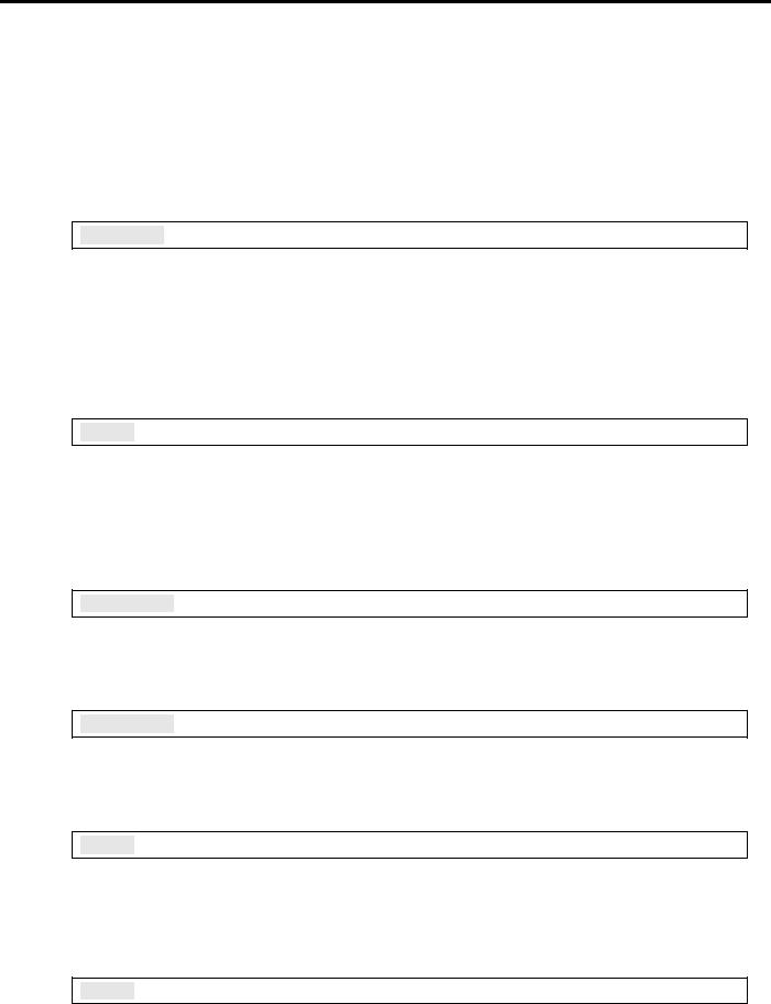
1.Open DCISoft in your PC and click on “Communication Setting”.
2. Select “Ethernet” as the transmission type.
|
14 |
DVP-PLC Operation Manual |

Ethernet Communication Module DVPEN01-SL
Broadcast search
1.Click broadcast icon in DCISoft to search for all Delta Ethernet products on the network. The window on the left hand side shows the models found, and the window on the right hand side displays the device list of all models.
2.Click a model on the left hand side, and you will see the device list of the model selected on the right hand side. Click the device to be set up to enter the setup page.
|
DVP-PLC Operation Manual |
15 |
Ethernet Communication Module DVPEN01-SL
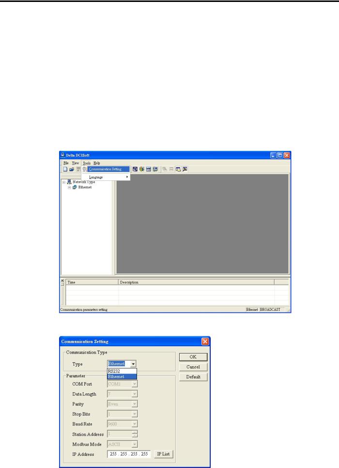
3. You will see the basic setup page as follow.
Designating model to search
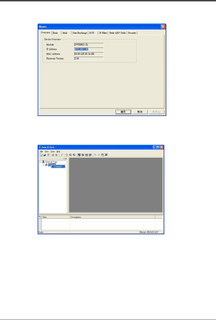
1.Right click “Ethernet” on the left hand side window and select “Configure” to designate a model to search for.
|
16 |
DVP-PLC Operation Manual |
 Loading…
Скачать
DVPEN01-SL
Ethernet Communication Module
Operation Manual
DVP-0204320-02
-
Страница 1
DVPEN01-SL Ethernet Communication Module Operation Manual DVP-0204320-02[…]
-
Страница 2
[…]
-
Страница 3
Ethernet Communication Module DVPEN01-SL DVP-PLC Operation Manual 1 Wa r n i n g 3 Please r ead this instruction carefully befor e use and fo llow th is instruction to operate th e device in or der to prevent damage s on the device or injuries to st aff. 3 Switch off the power befor e wiring. 3 RTU-DNET is an OPEN T YPE device and ther efor e shoul[…]
-
Страница 4
Ethernet Communication Module DVPEN01-SL DVP-PLC Operation Manual 2 5.10 Returning to Default Setting ……………………………………………………………………………………… .. 29 6 APPLICA TION EXAMPLES…………………………………………………………………………………………….. …. 30 6.1[…]
-
Страница 5
Ethernet Communication Module DVPEN01-SL DVP-PLC Operation Manual 3 1 Introduction Thank you for choosing DVPEN01-SL module. T o correctly install and operate DVPEN01-SL, please read the manual carefully before using the module. DVPEN01-SL is an Ethernet communication module for remote setting and communication through WPLSoft. DVPEN01-S L is able […]
-
Страница 6
Ethernet Communication Module DVPEN01-SL DVP-PLC Operation Manual 4 Item S pecification S torage: -25 ° C ~ 70 ° C (temperature), 5 ~ 95% (humidit y) Vibration/ Shock Resistance S tandard: IEC61 131-2, IEC 68 -2-6 (TEST Fc)/IEC61 131-2 & IEC 68-2-27 (TEST Ea) Electrical specifications Item S pecification Power supply voltage 24VDC (-15% ~[…]
-
Страница 7
Ethernet Communication Module DVPEN01-SL DVP-PLC Operation Manual 5 2.3 LED Indicators Indicator Color Indication POWER Green Power indication RS-232 Red Communication st atus of the series port 100M Orange Network connection st atus LINK Green Network communication speed 2.4 RJ-45 PIN Definition RJ-45 sketch Terminal No. Definition Explanation 1 T[…]
-
Страница 8
Ethernet Communication Module DVPEN01-SL DVP-PLC Operation Manual 6 Connect DVPEN01-SL to the Network: Connect DVPEN01-SL to t he Ethernet Hub by twisted pair cable CA T -5e. DVPEN01-SL has Auto MDI/MDIX function; therefore, DVPEN01-SL do es not need to use a crossing cabl e between the PC and DVPEN01-SL. Network connections between the PC and DVPE[…]
-
Страница 9
Ethernet Communication Module DVPEN01-SL DVP-PLC Operation Manual 7 CR# HW LW Attribute Content Explanation #7 R S tatus of E-Mail 1, 2 b0 ~ b7: Current status of E-Mail 2 b8 ~ b15: Current st atus of E-Mail 1 #8 R S tatus of E-Mail 3, 4 b0 ~ b7: Current status of E-Mail 4 b8 ~ b15: Current st atus of E-Mail 3 #9 R/W E-Mail 1 additional message Fil[…]
-
Страница 10
Ethernet Communication Module DVPEN01-SL DVP-PLC Operation Manual 8 CR# HW LW Attribute Content Explanation #1 15 R/W Modbus TCP trigger Setting up whether to send out dat a in Modbus TCP m ode #1 16 R/W Modbus TCP status Displayi ng current st atus of Modbus TCP mode #1 18 #1 17 R/W Modbus TCP destination IP Setting up destination IP address for M[…]
-
Страница 11
Ethernet Communication Module DVPEN01-SL DVP-PLC Operation Manual 9 CR#7 ~ 8: S tatus of E-Mail 1 ~ 4 Explanations: 1. CR#7_b0 ~ b7: current status of E-Mail 2; CR#7_b8 ~ b15: current status of E-Mail 1. 2. CR#8_b0 ~ b7: current status of E-Mail 4; CR#8_b8 ~ b15: current status of E-Mail 3. 3. Table of E-Mail status CR value E-Mail status 0 Not bee[…]
-
Страница 12
Ethernet Communication Module DVPEN01-SL DVP-PLC Operation Manual 10 CR value S tatus 0 Data have not yet been received. 1 Data excha nge is in progress. 2 Data excha nge is successful. 3 Data excha nge fails. CR#25, 26: Destination IP Explanations: T o set up the Slave IP address for dat a exchan ge manually , write “0” into CR#28 first before[…]
-
Страница 13
Ethernet Communication Module DVPEN01-SL DVP-PLC Operation Manual 11 CR#83: Read Length for Dat a Exchange Explanations: Setting up the Modbus address of the r egiste r for Master data exchange. CR#84: W ritten-in Address for Data Exchange Explanations: Setting up manually the Modbus addres s of t he register for Slave dat a exchange. CR#85: Writte[…]
-
Страница 14
Ethernet Communication Module DVPEN01-SL DVP-PLC Operation Manual 12 CR#1 14: Modbus TCP Time-O ut Explanations: Setting up the communication time-out (in ms) for Mo dbus TCP mode. CR#1 15: Modbus TCP Tr igger Explanations: When the CR value is set as “1”, Modbus TCP will be triggered. After the data transmissi on is completed in Modbus TCP mod[…]
-
Страница 15
Ethernet Communication Module DVPEN01-SL DVP-PLC Operation Manual 13 CR#251: Error Code Explanations: T able of error code: Bit No. Error b0 The network is not yet connected. b1 Incorrect IP setting b2 CR#13 is set as “tran smitting data”, but the dat a exchange is forbidden. b3 CR#13 is set as “tran smitting data”, but the dat a exchange m[…]
-
Страница 16
Ethernet Communication Module DVPEN01-SL DVP-PLC Operation Manual 14 5 Setting up Sof tware This section gives instructions o n how to set up DV PEN01 -SL by DCISoft and explanations on each setup page. Before you st art a setup page, you have to select “Ethernet” in the commu nic ation setting. Next, you can search by IP address or use Auto -S[…]
-
Страница 17
Ethernet Communication Module DVPEN01-SL DVP-PLC Operation Manual 15 Broadcast search 1. Click broadcast icon in DCISoft to search for all Delt a Ethernet products on the network. The window on the lef t hand side shows the model s foun d, and the window on the right hand side displays the device list of all models. 2. Click a model on the left[…]
-
Страница 18
Ethernet Communication Module DVPEN01-SL DVP-PLC Operation Manual 16 3. Y ou will see the basic setup page as follow . Designating model to search 1. Right click “Et hernet” on the left hand side windo w and select “Configure” to desi gnate a model to search for .[…]
-
Страница 19
Ethernet Communication Module DVPEN01-SL DVP-PLC Operation Manual 17 2. After configure a model, sele ct “DVPEN01-SL” and click “OK” to auto-search for DVPEN01-SL modules on the network. 3. Lis t of the current DVPEN01-SL modules[…]
-
Страница 20
Ethernet Communication Module DVPEN01-SL DVP-PLC Operation Manual 18 Searching by IP address 1. Set the communication type to “Etherne t” and enter the IP address. Click “OK”. 2. Click “IP Search” icon to st ar t searching for the designated IP . 3. The DVPEN01-SL module found will be displayed in the right hand side window . Double[…]
-
Страница 21
Ethernet Communication Module DVPEN01-SL DVP-PLC Operation Manual 19 Opening DVPEN01-SL setup page by RS-232 1. Select “RS232″ as the transmission type in communication setting. Y ou will have to designate a communication port. When DVPEN01-S L is searched by RS-232, you do not need to set up the parameters (i .e. data length, p arity , […]
-
Страница 22
Ethernet Communication Module DVPEN01-SL DVP-PLC Operation Manual 20 5.2 Basic Settings The basic settings in clude parameters a s module name, language, enabling Mo dbus TCP and time correction. Setting up DVPEN01-SL basics 1. Module Name: There can be many DVPEN01-SL mo dules in the network. Thus, y ou can set up a module name for each module[…]
-
Страница 23
Ethernet Communication Module DVPEN01-SL DVP-PLC Operation Manual 21 7. T ime Zone: A time zone is a region of the Earth that has adopted the same st andard time, usually referred to as the local time. Most adjacent time zones a re exactly one hour apart, and by convention compute their local time as an offset from Gr e enwich Mean T ime (see also […]
-
Страница 24
Ethernet Communication Module DVPEN01-SL DVP-PLC Operation Manual 22 3. Click on “Internet Protocol (TCP/IP). 4. Enter 192.168.0.1 into IP address. Click on “OK” to complete the IP address setting of the PC.[…]
-
Страница 25
Ethernet Communication Module DVPEN01-SL DVP-PLC Operation Manual 23 Setting up DVPEN01-SL Net work 1. IP configuration: There are two types of IP, static IP and DHCP. S tatic IP: Preset or manually modified by the user . DHCP: Automatically updated by the server . There has to be a server in the LAN. IP Explanation Static The user e nters the […]
-
Страница 26
Ethernet Communication Module DVPEN01-SL DVP-PLC Operation Manual 24 5.4 Setting up E-Mails E-mail is the abbreviation of electronic mail, which transmit s mails through the network. DVPEN01-SL has E-Mail functions for the user to pre-save a segment of text message s, which can be a descriptiv e message or error message, into the subject of the E-M[…]
-
Страница 27
Ethernet Communication Module DVPEN01-SL DVP-PLC Operation Manual 25 E-Mail will be sent to the desig nated recipient s w hen the E-Mail is triggered. T o trigger E-Mail, se t the value is CR#3 ~ CR#6 as “1”. 6. See “Applicat ion Examples Section 6.8” for more det ails. Notes: T o correctly send out E-Mails, there has to be a SMTP serve r i[…]
-
Страница 28
Ethernet Communication Module DVPEN01-SL DVP-PLC Operation Manual 26 receiving register In data exchange, DVPEN01-SL will execute Write ( Æ ) first before Read ( Å ). Quantity: A slave is able to send and receive at the same time maximum 100 con secutive data. f For data e xchange, D register is p arted into 2 sections, D0000 ~ D4 095 and D4096 ~[…]
-
Страница 29
Ethernet Communication Module DVPEN01-SL DVP-PLC Operation Manual 27 of every slave: Digital I/O point s (RX+RY): 256 Analog (Read) register: 64 Analog (Write) regi ster: 64 5.7 IP Filter IP filter is used for restri cting the connect ion of the network in case some uncert ain IP will cause errors. Onl y the IP set within a ce rtain range can e sta[…]
-
Страница 30
Ethernet Communication Module DVPEN01-SL DVP-PLC Operation Manual 28 Therefore, if you do not know the MA C address, you will have to spend some time looking up the MAC address. If you want to enhance the transmission ef ficiency , use stat ic ARP t able to save time. For example, assume IP: 192.168.0.1 and MAC: 00:14:22:56:0F:7F . As long as there[…]
-
Страница 31
Ethernet Communication Module DVPEN01-SL DVP-PLC Operation Manual 29 1. Modify: Check the box to modify the passwo rd. 2. New Password: Maximum 4 characters are allowed. Lea ve the column “blank” to disable the p assword protection function. 3. Confirm Password: Enter the new password a gain. 4. See “Application Examples Section 6.4” for mo[…]
-
Страница 32
Ethernet Communication Module DVPEN01-SL DVP-PLC Operation Manual 30 Check “Default Setting” box and click o n “Y es”. Note: If you set up DVPEN01-SL by RS-232, you can return the setti ng to default setting whether the password is locked or not. It takes approxim ately 10 seconds to return to default setting, so DO NOT switch of f the powe[…]
-
Страница 33
Ethernet Communication Module DVPEN01-SL DVP-PLC Operation Manual 31 3. Select “Ethernet” and press «OK”. 4. Click on “Auto-Search” icon to search for all DVPEN01-SL modules in the network. 5. Designate a DVPEN01 -SL and double click it to open the setup page.[…]
-
Страница 34
Ethernet Communication Module DVPEN01-SL DVP-PLC Operation Manual 32 6. Open “Basic” setup p age. 7. Switch to “Network” setup page[…]
-
Страница 35
Ethernet Communication Module DVPEN01-SL DVP-PLC Operation Manual 33 8. Enter IP address: 192.168.0.4; Netmask: 255.255.255.0; Gateway: 192.168.0.1. Press “OK” to complete the setup, and WPLSoft will automatically search for DVPEN01-SL. 9. The IP of DVPEN01-SL ha s been modified into the new setting (DELTA DVPEN01-SL: 192.168.0.4). 10. Click on[…]
-
Страница 36
Ethernet Communication Module DVPEN01-SL DVP-PLC Operation Manual 34 PC Hu b DH CP Serv er PC DVP- P LC DVPE N 01 2. Open “Communication Setting” in WPLSoft. 3. Select “Ethernet” and press “OK”.[…]
-
Страница 37
Ethernet Communication Module DVPEN01-SL DVP-PLC Operation Manual 35 4. Click on “Auto-Search” icon to search for a ll DVPEN01-SL modules in the network. Follow “View Æ Workspace Æ Communication” or “View Æ Workspace Æ Projec t” to find the detected DVPEN01-SL module (default module name: DELT A DVPEN01-SL, IP: 192.168. 1.5) in the […]
-
Страница 38
Ethernet Communication Module DVPEN01-SL DVP-PLC Operation Manual 36 6. Open the setup page. You can modify the modul e name for easier identification. 7. Next, set up the new IP of DVPEN01-SL. First s w itch to “Network” setup page. If there is a DHCP server in the LAN, select DHCP in “IP Configuration”. If there is no DHCP server in the L[…]
-
Страница 39
Ethernet Communication Module DVPEN01-SL DVP-PLC Operation Manual 37 6.3 Setting up Password and Clearing Password Application Setting up and clearing p assword by WPLSoft Network requirement (1) Set password in DVPEN01-SL (2) Unlock DVPEN01-SL (3) Clear the password in DVPEN01-SL 1. See 6.1 for the connection and how to set up the comm unication. […]
-
Страница 40
Ethernet Communication Module DVPEN01-SL DVP-PLC Operation Manual 38 5. Enter the password to temporarily unlock the protecti on and modify the parameters. If you close the setup page, the locking will automatically be recovered. 6. To clear the password, simply leave the passw ord columns blan k. Click on “OK” to clear the password.[…]
-
Страница 41
Ethernet Communication Module DVPEN01-SL DVP-PLC Operation Manual 39 7. After the password is cleared, you can modify the parameters. 6.4 When the Password is Lost (Retur ning to Default Setting by RS-232) Application Returning to default setting by RS-23 2 Network requirement (1) DVPEN01-SL is set with a password. (2) The password is forgotten. 1.[…]
-
Страница 42
Ethernet Communication Module DVPEN01-SL DVP-PLC Operation Manual 40 2. Check the “Default Setting” box an d the “Warning” dia log box will appear. Cli ck on “Yes” to ret urn to default setting (in approx. 5 ~ 10 seconds), and the password will be cleared as well. 3. After the searching, all the parameters ha ve already returned to thei[…]
-
Страница 43
Ethernet Communication Module DVPEN01-SL DVP-PLC Operation Manual 41 3. Check “Enable IP Filter Function” box. Enter “1 92.168.0.4” in No. 1 IP and “255.255.255.2 55” in all “Netmask” columns. 4. Enter “192.168.0.1” in No. 2 IP and “255.255.255.0” in No.2 “Netmask” column. Click on «OK” to complete the setting. On[…]
-
Страница 44
Ethernet Communication Module DVPEN01-SL DVP-PLC Operation Manual 42 6.6 Setting up St atic ARP T able Application Setting up static ARP table Network requirement (1) MAC address of equipment 192.168.1.6 is 00:18:23:10 :00:35 (2) MAC address of equipment 192.168.1.1 is 00:18:23:10 :00:04 1. See 6.1 for the connection and how to set up the communica[…]
-
Страница 45
Ethernet Communication Module DVPEN01-SL DVP-PLC Operation Manual 43 4. Enter “192.168.1.1” in No.2 IP, and its MAC address is “00:18:23:10:00:04”. Cli ck on “OK” to complete the setting. Only the equipment within the IP range can be connected. Note: The MAC address of D VPEN01-SL can be obtained from WPLS oft or the MAC address sticker[…]
-
Страница 46
Ethernet Communication Module DVPEN01-SL DVP-PLC Operation Manual 44 6.7 Application of E-Mail Application Sending an E-Mail to notify the administr ator when the current status of X0 and Y0 is changed. Network application (1) SMTP Server IP: 172.16.144.121 。 (2) E-mail address of administrator: test @sample.com (3) An E-mail message will be gene[…]
-
Страница 47
Ethernet Communication Module DVPEN01-SL DVP-PLC Operation Manual 45 4. Switch to “Select Recipients” pa ge. Check all the boxes of “Recipient 1”. C lick on “OK” to c omplete the setting. 5. After all the settings in DVPEN01-SL are comp leted, compile the ladder diag ram in the MPU and download it to the MPU. See below for the program d[…]
-
Страница 48
Ethernet Communication Module DVPEN01-SL DVP-PLC Operation Manual 46 1. See 6.1 for how to set up the communication. 2. Open the setup page of PLC_B and switch to “Data Exchange” p age. 3. Check “Enable Data Exchange” box. Select “Program Control” for Execute Mode. Enter IP address of PLC_A “192.168.0.4” in No. 1 Data Exchange Ho st[…]
-
Страница 49
Ethernet Communication Module DVPEN01-SL DVP-PLC Operation Manual 47 END M101 3 K100 K1 K1 K100 K100 K1 M2 M1 M1 SET M1 TOP K2 8 TOP TOP K29 K14 K13 K0 D100 K7 K100 K1 TOP K 1 SET M2 M1 RST K100 K1 M2 K14 D14 RS T M2 RS T M2 = D 1 4 K 2 = D 1 4 K 3 FROM D1 00 TD R M100 0 Explanations: • The data exchang e will be executed every one secon d. • W[…]
-
Страница 50
Ethernet Communication Module DVPEN01-SL DVP-PLC Operation Manual 48 6.9 Application of Dat a Exchan ge (2) Available in firmware V2.0 and later versio ns Application “Always Enable” Data Exchange. Enabl e a timer and write the timer values into D0 ~ D99. Continue to write the present values in D0 ~ D99 of PLC_A into D0 ~ D99 of PLC_B, and writ[…]
-
Страница 51
Ethernet Communication Module DVPEN01-SL DVP-PLC Operation Manual 49 6.10 Application of Dat a Exchange (3) Available in firmware V2.0 and later versio ns Application Enable a timer (X20) and write the timer values into D0 ~ D99. Control the program (X21 ) and write the present values in D0 ~ D99 of PLC_A into D0 ~ D99 of PLC_B, and write the value[…]
-
Страница 52
Ethernet Communication Module DVPEN01-SL DVP-PLC Operation Manual 50 After all the settings in PLC_A are completed, co mpi le the ladder diagram in the MPU and download it to PLC_A. See below for the program design: 6.11 Application of Dat a Exchange (4) Application Writing the time in RTC in PLC_B into D0 ~ D6 of PL C_A by designating IP by ladder[…]
-
Страница 53
Ethernet Communication Module DVPEN01-SL DVP-PLC Operation Manual 51 END M101 3 K100 K1 K100 K100 K1 M2 M1 M1 SET M1 TOP K 2 8 TOP TOP K100 TOP SET M2 M1 RST K100 K1 M2 K14 D14 RST M2 RST M2 = D 1 4 K2 = D 1 4 K 3 FROM K1 K100 K1 TOP K100 TOP K1 K1 K0 K0 K26 K25 K29 K14 K13 D100 K7 H4 HC0A8 D1 00 TD R M100 0 Explanations: • The data exchang e wil[…]
-
Страница 54
Ethernet Communication Module DVPEN01-SL DVP-PLC Operation Manual 52 6.12 Application of Dat a Exchange (5) Application Writing the time in RTC in PLC_B directl y into D0 ~ D6 of PLC_A without writing in ladder diagram into PLC_A. Network requirement (1) Adopting static IP. (2) IP of PLC_A: 192.168.0.4 (3) IP of PLC_B: 192.168.0.5 (4) Update from P[…]
-
Страница 55
Ethernet Communication Module DVPEN01-SL DVP-PLC Operation Manual 53 • Write “0” into CR#28, and PLC_B will u se CR# 25 ~ CR#26 as the IP address of the destination PLC. • Write the IP address of PLC_A into CR#25 and CR#26. The first two IP codes (192.168 = H’C0A8) should be written into CR#26, and the la st two IP codes (0.4 = H’0 004)[…]
-
Страница 56
Ethernet Communication Module DVPEN01-SL DVP-PLC Operation Manual 54 K100 K1 TOP K100 TOP K1 K1 K0 K100 K1 TOP K100 TOP K1 H0 K6 K125 K1 19 K1 16 K1 15 SET M2 M1 RST MOV K0 D0 = D 0 K2 INC D 0 END K100 K1 M2 D14 RS T M2 RS T M2 = D 1 4 K 2 = D 1 4 K 3 FROM K1 16 Explanations: • The data exchang e will be executed every one secon d. • Write the […]
-
Страница 57
Ethernet Communication Module DVPEN01-SL DVP-PLC Operation Manual 55 1. See 6.1 for how to set up the communication. 2. Use DCISof t for RTU-EN01 to set up the mapping CR for read/write. 3. Use DCISoft for DVPEN01-SL to set up the m apping start address and numbe r of dat a. RX: M2000 ~ M2009, RY : M3000 ~ M3009, RCR Read: D2000 ~ D20 009, RCR Writ[…]
-
Страница 58
Ethernet Communication Module DVPEN01-SL DVP-PLC Operation Manual 56 Explanations: 1. Enable mapping: CR15 = 1 2. Disable mapping: CR15 = 0 3. Once CR#15 is enabled, M2000 ~M2009 and D2000 ~ D2009 will read the data, and M3000 ~ M3009 and D3000 ~ D3009 will read the pre sent value before st arting to write. 4. During the execution of mapping, other[…]
File Specifications:1443/1443014-dvpen01sl.pdf file (18 Jul 2023) |
Accompanying Data:
Delta DVPEN01-SL Control Unit, Network Hardware PDF Operation Manual (Updated: Tuesday 18th of July 2023 12:44:30 PM)
Rating: 4.8 (rated by 37 users)
Compatible devices: AHBP06M1-5A, DVS Series, Agema Series, LE-764501, AC-160-DIN, IFD8540, CP2000 Series, MultiChoice T27 Series.
Recommended Documentation:
Operation Manual (Text Version):
(Ocr-Read Summary of Contents of some pages of the Delta DVPEN01-SL Document (Main Content), UPD: 18 July 2023)
-
32, Ethernet Communication Module DVPEN01-SL DVP-PLC Operation Manual 30 5. Please refer to section 6.15 for more information. 5.8 RTU Use the RTU function to conduct mapping between Delta’s network modules DVPEN01-SL and RTU-EN01.Set the mapping information first, and you will be able to use WPLSoft in DVPEN01-SL to save and retrieve the mapped bit (M) and register (D) in order to operate the remote RTU-EN01. Setting the RTU mapping 1. Enable Remote I/O Mapping…
-
13, Ethernet Communication Module DVPEN01-SL DVP-PLC Operation Manual 11 CR#29~48: Data transmission buffer Explanations: Storing the data to be transmitted to the remote MPU. CR#49~68: Data receiving buffer Explanations: Storing the data received from the remote MPU. CR#81: Read address for data exchange Explanations: Setting manually the MODBUS address of the register for Slave data exchange Only regi…
-
57, Ethernet Communication Module DVPEN01-SL DVP-PLC Operation Manual 55 • Write the IP address of PLC_A into CR#25 and CR#26. The first two IP codes (192.168=H’C0A8) should be written into CR#26, and the last two IP codes (0.4=H’0004) into CR#25. • Write the MODBUS address of D0 (H’1000) in PLC_A into CR#81 and CR#84. • Write the MODBUS address of D100 (register of RTC) (H’1064) into CR#86. • Write the number of registers K7 into CR#85. • Write “1” into CR#1…
-
42, Ethernet Communication Module DVPEN01-SL DVP-PLC Operation Manual 40 4. Open the setup page again, and DVPEN01-SL is now locked by the password. You cannot open any of the settings now. Click on Confirm to leave the entering password window. 5. Enter the password to temporarily unlock the protection and modify the parameters. If you close the setup page, the locking will automatically be recovered.
… -
10, Ethernet Communication Module DVPEN01-SL DVP-PLC Operation Manual 8 CR# Attribute Content Explanation HW LW #248~#220 — Reserved #251 R Error code Displaying the errors. See table of error codes in the following section for more information. #255~#252 — Reserved Symbols “R” refers to “able to read data by FROM instrcution”; “W” refers to “able to write data by TO instrcution”. …
-
17, Delta DVPEN01-SL Ethernet Communication Module DVPEN01-SL DVP-PLC Operation Manual 15 5 Setting the Software This section gives instructions on how to set DVPEN01-SL by DCISoft and explanations on each setup page. Before you start a setup page, you have to select Ethernet in the Communication Setting window. Next, you can search by IP address or use Auto-Search. You also can open the setup page for DVPEN01-SL by RS-232. DVPEN01-SL is set by UDP port 20006; there…
-
40, Ethernet Communication Module DVPEN01-SL DVP-PLC Operation Manual 38 5. After DELTA DVPEN01-SL in the Ethernet section is double-clicked, DCISoft will be started. Please refer to section 5.3 for more infomrationa bout setting an IP address. 6. After the setting of an IP address is complete, and step 2~step 4 are repeated, the IP address can be used for communication. 6.3 Setting a Password and Cl…
-
48, Delta DVPEN01-SL Ethernet Communication Module DVPEN01-SL DVP-PLC Operation Manual 46 6.7 Application of E-mails Application Sending an E-mail to notify the administrator when the current status of X0 and Y0 is changed. Network application (1) IP address of the SMTP server: 172.16.144.121 (2) E-mail address of administrator: [email protected] (3) An E-mail message will be generated when the status of X0 and Y0 is changed. 1.…
-
60, Ethernet Communication Module DVPEN01-SL DVP-PLC Operation Manual 58 Explanations: 1. Enabling mapping: CR15=1 2. Disabling mapping: CR15=0 3. After CR#15 is enabled, M2000~M2009 and D2000~D2009 will be used to read data, and present values will be read before M3000~M3009 and D3000~D3009 are used to write data. 4. During the execution of mapping, other devices can not be used to modify the values in mapping …
-
19, Ethernet Communication Module DVPEN01-SL DVP-PLC Operation Manual 17 3. You will see the basic setup page as follow. Designating a model to search 1. Right click Ethernet on the left hand side window and click Configure to designate a model to search for.
… -
22, Delta DVPEN01-SL Ethernet Communication Module DVPEN01-SL DVP-PLC Operation Manual 20 3. The DVPEN01-SL module found will be displayed in the right hand side window. Double click it to enter the setup page. Opening the DVPEN01-SL setup page by RS-232 1. Select RS232 as the transmission type in the Communication Setting window. You will have to designate a communication port. When DVPEN01-SL is searched by RS-232, you do not need to set the parameters (i.e…
-
8, Ethernet Communication Module DVPEN01-SL DVP-PLC Operation Manual 6 3.2 Connecting DVPEN01-SL to the Network: Connect DVPEN01-SL to the Ethernet Hub by twisted pair cable CAT-5e. DVPEN01-SL has Auto MDI/MDIX function; therefore, DVPEN01-SL does not need to use a crossing cable between the PC and DVPEN01-SL. Network connections between the PC and DVPEN01-SL: 4 Control Register (CR) 4.1 Control Registers in DVPEN01-…
-
36, Ethernet Communication Module DVPEN01-SL DVP-PLC Operation Manual 34 6 Application Examples 6.1 Setting an IP Address and Communication through WPLSoft Application Setting the network parameters of DVPEN01-SL directly on the PC. Network environment (1) IP address of the PC executing WPLSoft: 192.168.0.3 (2) Subnet mask: 255.255.255.0; Gateway: 192.168.0.1 (3) IP address of DVPEN01-SL: 192.168.0.4 (4) Connect the PC and DVPEN01-SL b…
-
20, Ethernet Communication Module DVPEN01-SL DVP-PLC Operation Manual 18 2. After configure a model, select the DVPEN01-SL checkbox and click OK to auto-search for DVPEN01-SL modules on the network. 3. List of the current DVPEN01-SL modules
… -
1, DVPEN01-SL Ethernet Communication Module Operation Manual DVP-0204320-04
… -
33, Ethernet Communication Module DVPEN01-SL DVP-PLC Operation Manual 31 5.9 IP Filter An IP filter is used for restricting the connection of the network in case some uncertain IP addresses will cause errors. Only the IP addresses set within a certain range can establish a connection. Other IP addresses will be rejected. Setting an IP filter 1. Enable IP Filter Check the box to enable IP filter. 2. IP Address IP addresses that are allowed to establish co…
-
Delta DVPEN01-SL User Manual
-
Delta DVPEN01-SL User Guide
-
Delta DVPEN01-SL PDF Manual
-
Delta DVPEN01-SL Owner’s Manuals
Recommended: 24PW9553/12, 7962, FW-C500, Race XXX Lite
Links & Tools
Operating Impressions, Questions and Answers: