Примечание: большая часть софта скачивается напрямую с сервера производителя, поэтому система не может определить размер файла и в колонке «размер» может стоять ‘0’
| Тип | Документ | Язык | Категория | Размер | Дата |
|---|---|---|---|---|---|
Программируемые контроллеры серий DVP / AX-3 / AS, панели оператора серий DOP, TP |
RU | Рекламные материалы | 38.99Mb | 08.09.2023 | |
ISPSoft v3.17 (ПО для контроллеров AS/AH/DVP. Совместимо с Windows® XP/Vista/7 (32-bit/64-bit)/8/10(64-bit) |
EN | Программное обеспечение | 0Mb | 16.05.2023 | |
COMMGR v.1.14 — integrated communication management software (Windows® XP/7(32-bit/64-bit)/8/10 (64-bit) |
EN | Программное обеспечение | 0Mb | 18.02.2022 | |
WPLSoft v2.51 (ПО для контроллеров DVP. Совместимо с Windows® XP/Vista/7(32-bit/64-bit)/8/10(64-bit) |
EN | Программное обеспечение | 0Mb | 30.11.2021 | |
Примеры программ для контроллеров DVP |
EN | Программное обеспечение | 52.77Mb | 16.06.2021 | |
Каталог «Программируемые контроллеры серий DVP/AH/AS и панели оператора DOP/TP» |
RU | Рекламные материалы | 27.08Mb | 09.06.2021 | |
Инструкция по совместному использованию симуляторов панелей оператора Delta DOP-100 и контроллеров Delta AS/DVP/AH |
RU | Руководства пользователя | 2.97Mb | 16.11.2020 | |
Сертификат соответствия EAC на ПЛК серий AS/AH/DVP 24В (2020-2025) |
RU | Сертификаты | 1.56Mb | 20.10.2020 | |
Примеры программ для ПЛК DVP и панелей оператора DOP-100 |
EN | Программное обеспечение | 56.81Mb | 05.10.2020 | |
Руководство по программированию DVP-ES2/EX2/SS2/SA2/SX2/SE & TP04P |
EN | Руководства пользователя | 11.5Mb | 15.09.2020 | |
Каталог по ПЛК Delta |
EN | Рекламные материалы | 6Mb | 13.08.2020 | |
Каталог «Программируемые контроллеры серий DVP/AH/AS и панели оператора DOP/TP |
RU | Рекламные материалы | 38.79Mb | 12.08.2020 | |
Свидетельство об утверждении типа средств измерения DVP |
RU | Сертификаты | 0.94Mb | 30.07.2020 | |
Сертификат соответствия EAC на ПЛК серий AS/AH/DVP (2019-2024) |
RU | Сертификаты | 2.14Mb | 21.01.2020 | |
Каталог «Программируемые контроллеры серий DVP/AH/AS и панели оператора DOP/TP» |
RU | Рекламные материалы | 24Mb | 19.03.2019 |
Перейти к контенту
Примечание: большая часть софта скачивается напрямую с сервера производителя, поэтому система не может определить размер файла и в колонке «размер» может стоять ‘0’
Категория файлов:
| Тип | Документ | Язык | Категория | Размер | Дата |
|---|---|---|---|---|---|
ISPSoft v3.16 (ПО для контроллеров AS/AH/DVP. Совместимо с Windows® XP/Vista/7 (32-bit/64-bit)/8/10(64-bit) |
EN | Программное обеспечение | 0Mb | 30.06.2022 | |
COMMGR v.1.14 — integrated communication management software (Windows® XP/7(32-bit/64-bit)/8/10 (64-bit) |
EN | Программное обеспечение | 0Mb | 18.02.2022 | |
WPLSoft v2.51 (ПО для контроллеров DVP. Совместимо с Windows® XP/Vista/7(32-bit/64-bit)/8/10(64-bit) |
EN | Программное обеспечение | 0Mb | 30.11.2021 | |
Примеры программ для контроллеров DVP |
EN | Программное обеспечение | 52,77Mb | 16.06.2021 | |
Каталог «Программируемые контроллеры серий DVP/AH/AS и панели оператора DOP/TP» |
RU | Рекламные материалы | 27,08Mb | 09.06.2021 | |
Инструкция по совместному использованию симуляторов панелей оператора Delta DOP-100 и контроллеров Delta AS/DVP/AH |
RU | Руководства пользователя | 2,97Mb | 16.11.2020 | |
Сертификат соответствия EAC на ПЛК серий AS/AH/DVP 24В (2020-2025) |
RU | Сертификаты | 1,56Mb | 20.10.2020 | |
Примеры программ для ПЛК DVP и панелей оператора DOP-100 |
EN | Программное обеспечение | 56,81Mb | 05.10.2020 | |
Руководство по программированию DVP-ES2/EX2/SS2/SA2/SX2/SE & TP04P |
EN | Руководства пользователя | 11,5Mb | 15.09.2020 | |
Каталог по ПЛК Delta |
EN | Рекламные материалы | 6Mb | 13.08.2020 | |
Каталог «Программируемые контроллеры серий DVP/AH/AS и панели оператора DOP/TP |
RU | Рекламные материалы | 38,79Mb | 12.08.2020 | |
Свидетельство об утверждении типа средств измерения DVP |
RU | Сертификаты | 0,94Mb | 30.07.2020 | |
Сертификат соответствия EAC на ПЛК серий AS/AH/DVP (2019-2024) |
RU | Сертификаты | 2,14Mb | 21.01.2020 | |
Каталог «Программируемые контроллеры серий DVP/AH/AS и панели оператора DOP/TP» |
RU | Рекламные материалы | 24Mb | 19.03.2019 | |
Инструкция по программированию контроллеров DVP [Внимание! Версия 2013 г., сверяйтесь с последней версией на англ. языке] |
RU | Руководства пользователя | 11,78Mb | 04.12.2018 |
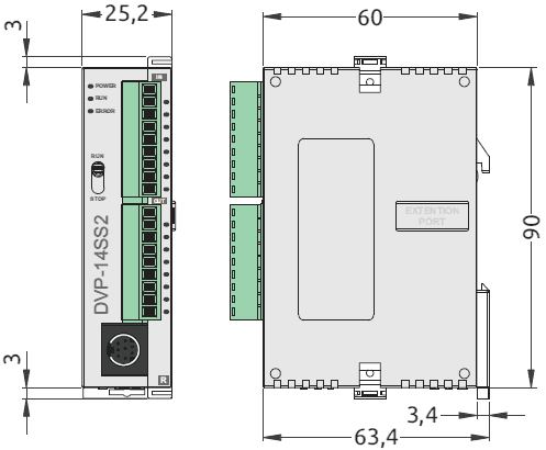
14 точек дискретного ввода/вывода (8DI + 6DO)
Шина расширения до 480 вх/вых
Выгодная цена
ModBUS COMx2, RS-232 / RS-485
Высокоскоростные входы, < 20 кГц
- ЦПУ: 14 точек дискретного ввода/вывода (8DI + 6DO).
- Расширение до 480 вх/вых.
- Память: программа – 8 К шагов, регистры данных – 5 К слов.
- Время обработки инструкций: базовая – 0,35…1 мкс, прикладная (MOV) – 3,4 мкс.
- Два COM-порта: RS-232, RS-485 (Modbus, ASCII / RTU).
- 4 высокоскоростных импульсных выхода: 10 кГц.
- 8 каналов высокоскоростного счета и внешних прерываний: 4 входа по 20 кГц и 4 выхода по 10 кГц.
- Бесплатное ПО.
| Артикул | DVP14SS211R | DVP14SS211T |
|---|---|---|
| Напряжение питания | =24 В (-15%, +20%), с защитой от переполюсовки | |
| Потребляемая мощность | 1,8 Вт | |
| Входы | ||
| Тип входа | PNP или NPN | |
| Потребляемый ток | 5 мА при =24 В | |
| Время фильтрации | 10 мс (регулируется в диапазоне 0-20 мс, регистр D1020) | |
| Выходы | Реле | Транзистор |
| Максимальный ток | 1,5 А / 1 точка (5 А общий) | 0,5 А / 1 точка (3 А общий) |
| Рабочее напряжение | ~250 В, < =30 В | =5…30 В |
| Максимальная нагрузка (индуктивная) | см. руководство по эксплуатации | 15 Вт (=30 В) |
| Время реакции | около 10 мс | выкл. – вкл. (Y0-Y3) 20 мкс, (Y4, Y5) 100 мкс вкл. – выкл. (Y0-Y3) 30 мкс, (Y4, Y5) 100 мкс |


Hello everyone!
In some previous posts plc247.com wrote an article to guide you to use PLC Delta DVP14SS2 to control Servo Motor Yaskawa Sigma 7 & Mitsubishi MR-J4-A.
- Mitsubishi FX3U ” Stepping Motor” Control Tutorial
Today plc247.com will continue to guide you to use the Delta PLC to control the stepper motor using Driver DM542, this is a very popular driver used all over the world because of its extremely cheap price but good quality.
Delta DVP-14SS2 & DM542 Driver “Wiring Diagram”
Note: Most Step Controllers can only control = 5V signal. With DM542 Driver we can control from 5 > 24 V
+ R= 2K2Ω: Reduce voltage from 24VDC to 5VDC
+ DM542 Setting 1000PLS = 1 Rev.
PLC Delta Programming
+ Simple program to control Stepping Motor
Project Video Example
======
Required Software
- Download PLC Delta Programming Software
Please share the article to the community if you find it useful. Subscribe to Youtube channel and Website to read new articles from plc247.com
Thanks and Best Regards!
You may also like
About the author
plc247.com
 |
|
 |
||||||||||||||||||||||||||||||||||||||||||||||||||||||||||||||||||||||||||||||||||||||||||||||||||||||||||||||||||||||||||||||||||||
|
ООО НПК «Промпривод » 150008, г. Ярославль, пр. Машиностроителей, д. 83. ПОКАЗАТЬ СХЕМУ ПРОЕЗДА Червячный редуктор, цилиндрический редуктор, мотор редуктор от ведущего поставщика редукторов. Создание и продвижение сайтов в Ярославле. «Perspektiva» |
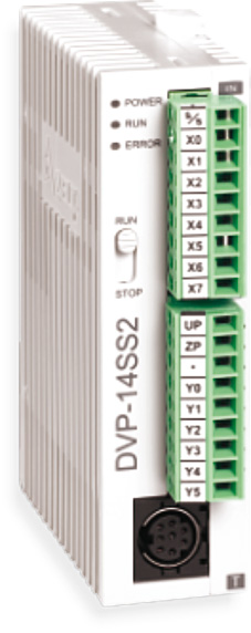
The Delta DVP SS2-S is the slim type Second Generation Programmable Logic Controller (PLC) of Delta Electronics. The DVP SS2 Programmable Logic Controller (PLC) Includes 0ne 12-point Programmable Logic Controller (PLC) and two 14-point Programmable Logic Controller (PLC). A DVP SS2 Series Programmable Logic Controller (PLC) provides various types of instructions, Small Sizes, and Program Capacity is 8k Steps. However, Today plchmiservo.com would like to share the [Download] 14SS2 Manual Delta PLC Programming Manual also how to download the manual.
DVP SS2 Series Programmable Logic Controller (PLC) is able to connect all DVP-S Series Extension Modules, Including Digital Input Output Module (Maximum 480 I/O Points), Analog Input Module AD, Analog Output Module DA, Temperature Module PT, and TC. DVP SS2 Series Programmable Logic Controller (PLC) Supports 08 Extension Modules. DVP SS2 Series Programmable Logic Controller has 04 groups of High Speed (10KHZ) Pulse Output.
User Can Easily Install the PLC, Also User Does not has to install any batteries in the delta DVP SS2 Series Programmable Logic Controller (PLC). DVP SS2 Series (PLC) Program and Latched data stored in the Flash Memory. DVP SS2 Series Programmable Logic Controller used for Small projects and medium projects, also used in various types of Factories. Today plchmiservo.com would like to share the Manual Delta DVP SS2 Series User Manual and Delta PLC Programming Example Manual with you.
Specification of the Delta DVP14-SS2-S PLC
+Power Supply Voltage: 24V DC (-15% ~ 20 %) With counter connection Protection on the DC Input Power.
+Digital Input Number: 8 Points X0, X1…..X7
+Digital Output Number: 6 points Y0, Y1…Y6
+Input Type: DC (Sink or Source)
+Communication Port: Two Communication Port COM1 RS232 and COM2 RS485 MODBUS ASCII/RTU Mode.
Note That: The Power is connected to Two terminals 24C DC and 0V, the range of power (20.4 V DC to 28.8 V DC). If the Power input Voltage is Less than 20.4 V DC, the Programmable Logic Controller (PLC) will stop running; all outputs will be off, also Error Indicator Blinking Continuously.
Program of the Delta DVP14SS2-S PLC
+Step 01: At First Download the Software from our Website then Extract it and Install then Open the Software WPLSoft V2.51, or Others Version then click on File then click on New and Select the Model then click OK and Edit the Program
+ Step 2: After Programming the PLC DVP14SS2-S then Simulation the program, So Click on Simulator Click on Online, and click on Run.
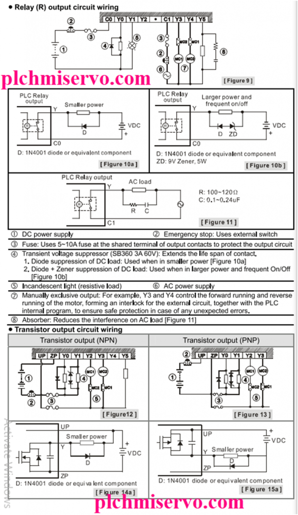
Wiring Diagram of the Delta DVPSS2-S
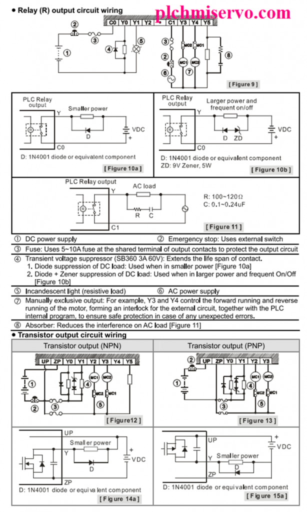
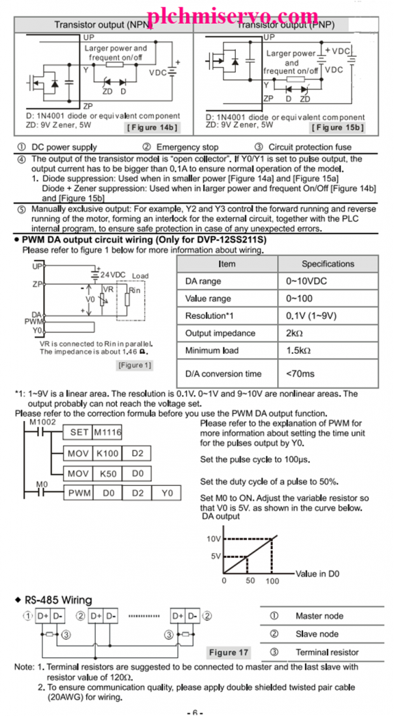
+Step 01: Digital Input and Output Wiring Connection of DVP-SS2-S Programmable Logic Controller (PLC), Also COM2 RS485 Wiring Connection.
>>>> Download 14SS2 Manual Delta PLC Programming Manual Google Drive Link>>>>
We have given the link [Download] 14SS2 Manual Delta PLC Programming Manual on google drive so click on the link to download your required manual.
+ [Download] Delta DVP14SS2-S Manual Delta PLC Programming Manual
Download Link:
https://drive.google.com/file/d/1PE4ZQlk4yar7OAfZEZSNDBZ4r2bFboZc/view?usp=sharing
Link: + [Download] DVP Series Delta PLC Programming Examples Manual
Thanks for Reading our Article In you need a DVP14SS2 Programmable Logic Controller or any help with Software, Programming examples, and Manual Link, Please contact our admin via mail or WhatsApp.
+Delta HMI
+Delta servo
Contents
6
Table of Contents
7
PLC Concepts
11
PLC Scan Method
12
Scanning Process
12
Input Signal
12
Scan Time
12
Current Flow
13
NO Contact, NC Contact
13
PLC Registers and Relays
13
Reverse Current
13
Ladder Logic Symbols
14
Creating a PLC Ladder Program
15
Execution Order of the Sample Program
15
LD / LDI (Load no Contact / Load NC Contact)
16
Or / Ori
16
LDP / LDF (Load Rising Edge Trigger/ Load Falling Edge Trigger)
16
AND / ANI (Connect no Contact in Series / Connect NC Contact in Series)
16
ANDP / ANDF (Connect Rising Edge in Series/ Connect Falling Edge in Series)
16
ORP / ORF (Connect Rising Edge in Parallel/ Connect Falling Edge in Parallel)
16
ANB (Connect Block in Series)
16
ORB (Connect Block in Parallel)
17
MPS / MRD / MPP (Branch Instructions)
17
STL (Step Ladder Programming)
17
RET (Return)
18
Conversion between Ladder Diagram and Instruction List Mode
19
Fuzzy Syntax
20
Correcting Ladder Diagram
21
Basic Program Design Examples
23
Example 1 — Stop First Latched Circuit
23
Example 2 — Start First Latched Circuit
23
Example 3 — Latched Circuit of SET and RST
23
Example 4 — Power down Latched Circuit
24
Example 5 — Conditional Control
24
Example 6- Interlock Control
24
Example 7 — Sequential Control
24
Example 8 — Oscillating Circuit
25
Example 9 – Oscillating Circuit with Timer
25
Example 10 — Flashing Circuit
25
Example 11 — Trigger Circuit
25
Example 13 — Output Delay Circuit
26
Example 14 — Timing Extension Circuit
26
Example 15 – Counting Range Extension Circuit
26
Example 16 — Traffic Light Control (Step Ladder Logic)
26
Wplsoft Programming (SFC Mode)
29
Programming Concepts
31
ES2/EX2 Memory Map
32
SS2 Memory Map
34
SA2/SX2 Memory Map
36
SE Memory Map
39
Status and Allocation of Latched Memory
41
PLC Bits, Nibbles, Bytes, Words, Etc
42
Binary, Octal, Decimal, BCD, Hex
42
M Relay
43
S Relay
52
T (Timer)
53
Accumulative Timer
53
Timers for Subroutines and Interrupts
53
C (Counter)
54
High-Speed Counters
55
Applicable Software High Speed Counters
56
AB-Phase Input High-Speed Counter
59
Special Data Register
60
E, F Index Registers
69
Nest Level Pointer[N], Pointer[P], Interrupt Pointer [I]
70
CJ Condition Jump
70
CALL Subroutine, SRET Subroutine END
70
External Interrupt
71
Timer Interrupt
71
Counter Interrupt
71
Communication Interrupt
71
Applications of Special M Relays and D Registers
72
Special M and Special D Relevant to RTC
74
Adjustment on Input Terminal Response Time
75
X6 Pulse Width Detecting Function
75
Communication Error Code
75
Pulse Output Mark and Mask Function
76
Execution Completed Flag
76
Clear Instruction
76
Function Group COM Port Function
77
Output State Latched in STOP Mode
77
Disabling All y Outputs
77
RUN/STOP Switch
77
Modifying COM1 Communication Format
78
Modiying COM2 Communication Format
78
Modifying COM3 Communication Format
79
RTU Mode Setting of COM1、COM2、COM3
79
Enable SPD Function
80
Communication Response Delay
80
Fixed Scan Time
81
Analog Function Built in the PLC
81
The Description of D1113 for 30EX2
82
The Status of the Analog Input Channel of 30EX2
82
The Upper/Lower Limit Values for the Analog Input Mode of 30EX2
82
The Description of D1115 for 30EX2
83
The Analog Input Modes for 30EX2
83
Enable 2-Speed Output Function of DDRVI/DDRVA Instruction
83
Program Execution Error
85
I/O Modules Detection
85
Reverse Interrupt Trigger Pulse Direction
85
Stores Value of High-Speed Counter When Interrupt Occurs
85
Enabling Force-ON/OFF of Input Point X
86
ID of Right Side Modules on ES2/EX2/SS2/SA2/SX2/SE
86
ID of Left Side Modules on SA2/SX2/SE
87
Mapping Function for Right-Side High-Speed Special Modules
87
Output Clear Signals When ZRN Is Completed
87
Plc Link
87
Frequency Detection Function
99
Fetching the Value in a Hardware Counter
99
Instruction Set
101
Basic Instructions (Without API Numbers)
102
Explanations to Basic Instructions
102
Pointers
113
Application Programming Instructions
115
Instruction Composition
115
Length of Operand (16-Bit or 32-Bit Instruction)
116
16-Bit MOV Instruction
116
32-Bit DMOV Instruction
116
Explanation of the Format of Application Instruction
116
Continuous Execution Vs. Pulse Execution
117
Pulse Execution Instruction
117
Continuous Execution Instruction
117
Operands
117
Kn Values
118
Flags
118
General Flags
118
Error Operation Flags
119
Flags to Extend Functions
119
Limitations for Times of Using Instructions
119
Limitation of Synchronized Execution
120
Numeric Values
120
Assign Continuous Bit Numbers
121
Floating Point Operation
121
Application Instructions Revelant to Floating Point
121
Binary Floating Point
122
Decimal Floating Point
122
Numerical List of Instructions (Classified According to the Function)
124
Loop Control
124
Transmission Comparison
124
Four Arithmetic Operations
124
Rotation and Displacement
125
Data Processing
125
High Speed Processing
125
Handy Instructions
126
External I/O Display
126
Serial I/O
126
Basic Instructions
127
Communication Instructions
127
Additional Instruction
129
Positioning Control
129
Real Time Calendar
130
Gray Code
130
Matrix Operation
130
Contact Type Logic Operation
131
Contact Type Comparison
131
Specific Bit Control
132
Floating-Point Contact Type Comparison
132
Numerical List of Instructions (in Alphabetic Order)
134
Detailed Instruction Explanation
141
Interrupt Return
148
Enable Interrupt
148
Disable Interrupt
148
CJ Instruction Program Flow
152
CALL Instruction Program Flow
153
Watchdog Timer Refresh
154
Start of a FOR-NEXT Loop
156
End of a FOR-NEXT Loop
156
Compare
159
Zone Compare
160
Move
161
Shift Move
162
Compliment
165
Block Move
166
Fill Move
168
Exchange
169
Convert bin to BCD
171
Convert BCD to bin
172
4-Digit DIP Switch in BCD Format
173
4-Digit 7-Segment Display in BCD Format
173
Addition
175
Subtraction
177
Multiplication
178
Division
180
Increment
182
Decrement
183
Logical Word and
184
Logical Dword and
185
Logical Word or
186
Logical Dword or
187
Logical Word XOR
188
Logical Dword XOR
189
2’S Complement
190
Ss2Sx230Drorprotation
192
Rotate Left
193
Rotation Right with Carry
194
Rotation Left with Carry
195
Bit Shift Right
196
Bit Shift Left
197
Word Shift Right
198
Word Shift Left
200
Shift Register Write
201
Shift Register Read
202
Zone Reset
203
Decode
205
Encode
207
Sum of Active Bits
209
Check Specified Bit Status
210
Mean
211
Timed Annunciator Set
212
Annunciator Reset
213
Square Root
215
Floating Point
216
Refresh
219
Refresh and Filter Adjust
221
Input Matrix
223
High Speed Counter Set
226
Block Diagram of Software Counters and Comparators:
227
High Speed Counter Reset
233
High Speed Zone Compare
234
Speed Detection
238
Pulse Output
240
Description of Associated Special D Registers
243
More Explanations for M1347,M1348, M1524, M1525
243
Pulse Width Modulation
245
Pulse Ramp
247
Explanations on Associated Flags and Registers
249
Description on Associated Flags
249
Description on Associated Special Registers
250
Operation of Mark Function on Y0
250
Operation of Mask Function on Y0
252
Adding Mask and Alignment Mark Function for CH0 and CH1
253
Execution of the Mask Function (Use Y0 as an Example)
254
Adding Fixed Slope Function for CH0 and CH1
254
Y1 and Y3 Relative Parameters for Alignment Mark Function
255
Y1 and Y3 Relative Parameters for Fixed Slope Function
255
Robot Arm Control (by ist Instruction)
257
Control Purpose
257
Motion of the Robot Arm
257
I/O Devices
257
START Circuit
258
Manual Mode
258
Zero Return Mode
258
Ladder Diagram
259
Auto Operation
259
Flag Explanation
261
Disable “All Output Reset” Function
261
Incremental Drum Sequencer
266
Teaching Timer
268
Special Timer
270
Alternate State
272
Ramp Variable Value
273
Data Transform and Move
275
Data Sort
293
Ten Key Input
296
Hexadecimal Key Input
298
DIP Switch
301
7-Segment Decoder
303
7-Segment with Latch
304
Arrow Switch
308
ASCII Code Conversion
310
Print (ASCII Code Output)
311
Read CR Data from Special Modules
313
Write CR Data into Special Modules
315
Serial Communication
317
Example Program of RS-485 Communication
339
Rising-Edge Output
371
Rising–Edge Detection Operation
372
Falling–Edge Detection Operation
373
Rising-Edge Series Connection
374
Falling-Edge Series Connection
375
Rising-Edge Parallel Connection
376
Falling-Edge Parallel Connection
377
Timer
378
16-Bit Counter
379
32-Bit Counter
380
Inverse Operation
381
Falling-Edge Output
382
Read Modbus Data
383
Registers for Received Data (Responding Messages)
385
Communication between PLC and VFD-B Series AC Motor Drive
386
Registers for Data to be Sent (Sending Messages)
386
Write Modbus Data
388
Communication between PLC and VFD-B Series AC Motor Drives
389
Reverse Operation of VFD
393
Stop VFD
393
Read VFD Status
398
Reset Abnormal VFD
402
LRC Checksum
405
CRC Checksum
408
Floating Point Compare
410
Floating Point Zone Compare
411
Move Floating Point Data
412
Ethernet Communication
413
16-Bit Multiplication
416
32-Bit Multiplication
416
Degree/Radian
420
Float to Scientific Conversion
422
Scientific to Float Conversion
423
Floating Point Addition
425
Floating Point Subtraction
426
Floating Point Multiplication
427
Floating Point Division
428
Float Exponent Operation
429
Float Natural Logarithm Operation
430
Float Logarithm Operation
431
Floating Point Square Root
432
Floating Point Power Operation
433
Float to Integer
435
Sine
436
Cosine
438
Tangent
440
Arc Sine
442
Arc Cosine
444
Arc Tangent
446
Delay
447
General PWM Output
450
Fuzzy Temperature Control
451
Byte Swap
457
Reading the Data from the File Register
458
Writing the Data into the File Register
459
MODBUS Read/ Write
460
Mov H87
479
Set M1120
479
Mov K100
479
Rst M1143
479
Receiving Completed
479
M1143 = off ASCII Mode
479
ASCII Mode (M1143 = OFF)
480
When X0 = ON, MODRW Instruction Executes the Function Specified by Function Code
480
Set Communication Protocol as 9600, 8, E
483
Retain Communication Protocol
483
Set Communication Timeout as 100Ms
486
Data Address: H2000
486
Connection Device
487
Address: K1
487
Absolute Position Read
491
Zero Return
496
Adjustable Speed Pulse Output
502
Relative Position Control
503
Absolute Position Control
507
Time Compare
510
Time Zone Compare
511
Time Addition
512
Time Subtraction
513
Time Read
515
Time Write
517
Transfer Designated Bits
519
Hour Meter
520
BIN — Gray Code
522
Gray Code — bin
523
GPS Data Receiving
529
Sum of Multiple Devices
535
Matrix and
537
Matrix or
539
Matrix XOR
540
Matrix XNR
541
Matrix Inverse
542
Matrix Compare
543
Matrix Bit Read
545
Matrix Bit Write
547
Matrix Bit Shift
549
Matrix Bit Rotate
551
Matrix Bit Status Count
553
2-Axis Relative Point to Point Motion
554
2-Axis Absolute Point to Point Motion
557
Single-Axis Pulse Output by Table
567
Close Loop Position Control
569
Variable Speed Pulse Output
576
Immediately Change Frequency
580
Proportional Calculation
583
Parameter Proportional Calculation
585
Compare Table
589
ASDA Servo Drive R/W
591
Catch Speed and Proportional Output
594
Serial Type Logic Operation
597
Parallel Type Logic Operation
598
Serial Type Comparison
600
Parallel Type Comparison
601
Contact Type Timer
602
Output Specified Bit of a Word
603
Set on Specified Bit of a Word
604
Reset Specified Bit of a Word
605
Load no Contact by Specified Bit
606
Load NC Contact by Specified Bit
607
Connect no Contact in Series by Specified Bit
608
Connect NC Contact in Series by Specified Bit
609
Connect no Contact in Parallel by Specified Bit
610
Connect NC Contact in Parallel by Specified Bit
611
Floating Point Contact Type Comparison LD
612
Floating Point Contact Type Comparison and
613
Floating Point Contact Type Comparison or
614
DMV Communication Command
615
Communication Combination Function Code
616
Comparing Contact Type Absolute Values LDZ
620
Comparing Contact Type Absolute Values ANDZ
622
Comparing Contact Type Absolute Values ORZ
624
Self-Defined Ethernet Communication Port
626
TCP Socket Connection
630
Communications
633
Communication Ports
634
Communication Format
634
Communication Protocol ASCII Mode
635
Communication Data Structure
635
ADR (Communication Address)
635
CMD (Command Code) and DATA
636
LRC CHK (Checksum)
637
Exception Response
637
Communication Protocol RTU Mode
639
Address (Communication Address)
639
CRC CHK (Check Sum)
640
PLC Device Address
642
Command Code
644
Command Code: 02, Read Status of Contact (Input Point X Is Included)
645
Command Code: 03, Read Content of Register (T, C, D)
646
Command Code: 05, Force ON/OFF Single Contact
647
Command Code: 06, Set Content of Single Register
648
Command Code: 15, Force ON/OFF Multiple Contacts
648
Command Code: 16, Set Content of Multiple Registers
649
Sequential Function Chart
651
Step Ladder Instruction [STL], [RET]
652
Sequential Function Chart (SFC)
652
The Operation of STL Program
654
Actions of Step Points
654
STL Transition
655
Repeated Usage of Output Coil
655
Repeated Usage of Timer
656
Transfer of Step Points
656
SET Sn
656
OUT Sn
657
Restrictions on Using Certain Instructions
658
Basic Instructions Applicable in a Step
658
Points to Note for Designing a Step Ladder Program
660
Sequence Jump
661
Restrictions on Diverging Sequence
661
Reset Step Points and Disable Output
661
Latched Step
661
Types of Sequences
662
Single Sequence: the Basic Type of Sequence
662
Single Sequence Without Divergence and Convergence
662
Step Jump
663
Reset Sequence
663
Structure of Simultaneous Divergence
664
Structure of Alternative Divergence
664
Ladder Diagram of Simultaneous Divergence
664
SFC Diagram of Simultaneous Divergence
664
Structure of Simultaneous Convergence
665
Structure of Alternative Convergence
665
Example of Alternative Divergence & Alternative Convergence
666
Example of Simultaneous Divergence & Simultaneous Convergence
667
Example of the Simultaneous Divergence & Alternative Convergence
668
Restrictions on Divergence Sequence
671
IST Instruction
673
Control Panel
675
Troubleshooting
679
Common Problems and Solutions
680
Error Code Table (Hex)
682
Error Detection Devices
684
Canopen Function and Operation
685
The Introduction of Canopen
686
The Description of the Canopen Functions
686
The Input/Output Mapping Areas
687
The Installation and the Network Topology
687
The Dimensions
687
The Profile
688
The CAN Interface and the Network Topology
688
The Pins of COM3 (CAN Interface)
688
The CAN Signal and the Data Frame Format
688
The CAN Network Endpoint and the Topology Structure
689
The Topology Structure of the Canopen Network
690
The Canopen Protocol
693
The Introduction of the Canopen Protocol
693
The Object Dictionary
693
The Canopen Communication Object
694
SDO (Service Data Object)
695
The Format of the Reply Message
696
NMT (Network Management Object)
696
Module Control Services
696
Error Control Services
697
Boot-Up Services
698
Other Predefined Canopen Communication Objects (SYNC and EMCY)
698
Emergency Object
699
The Predefined Connection Set
699
Data Structure of SDO Request Message
700
Sending SDO, NMT and Reading Emergency Message through the Ladder Diagram
700
Data Structure of NMT Message
702
The Data Format of the NMT Response Message
703
Data Structure of EMERGENCY Request Message
703
The Data Format of the Emergency Response Message
704
Emergency Response Data
705
Example on Sending SDO through the Ladder Diagram
705
Explanation of Request Message Devices
706
Editing the Ladder Diagram through Wplsoft
706
Indicators and Troubleshooting
707
Explanation of Response Message Devices
707
POWER Indicator
707
RUN Indicator
707
Canopen Network Node State Display
708
Application Example
710
Hardware Connection
710
Setting Servo Parameters
710
Setting Canopen Baud Rate and Node ID of DVP-ES2-C
711
Network Scanning
714
Node Configuration
714
“Error Control Protocol”
714
“Auto SDO Configuration”
714
PDO Mapping
715
PDO Transmission Type
715
Program Explanation
717
The Mapping Relation between Master and Slave
717
Object Dictionary
718
Installing a USB Driver in the PLC
727
A.1 Installing the USB Driver in Windows 7
728
A.2 Installing the USB in Windows 8
730
A.3 Installing the USB Driver in Windows 10
733
Setting and Using an Ethernet Plc/Module
735
Specifications for an Ethernet Plc/Module
736
Ethernet Control Registers
736
Station Addresses of Ethernet Modules
736
DVPEN01-SL (Left-Side Ethernet Communication Module)
738
DVP-FEN01 (DVP-EH3 Series Ethernet Communication Card
740
Searching for an Ethernet PLC
740
B.3.1 Communication Setting
741
B.3.2 Broadcast Search
742
Searching for a Model Specified
743
B.3.4 Searching by an IP Address
745
Ethernet/Ip List
746
Data Exchange
746
B.4 Data Exchange
746
Ethernet/Ip Information Supported by DVP-SE Series Plcs
747
Ethernet/Ip Objects Supported by DVP-SE Series Plcs
748
TCP/IP Interface Object
750
Ethernet Link Object
750
Setting the RTU Mapping
751
B.6 RTU Mapping
751
Application of the RTU Mapping
752
Inforamation about TP Series Text Panels
755
C.1 TP Memory Map
756
Special Data Register
757
Special Auxiliary Relay
766
Instructions Applicable to TP
775
Basic Instructions
775
C.4 Instructions Applicable to TP
775
Numerical List of Instructions
776
Additional Remarks on High-Speed Instructions
780
D.1 Current Consumption of a Slim Plc/An Extension Module
781
Current Supply and Current Consumption of a PLC (+24VDC)
782
Current Consumption of a Slim Plc/An Extension Module
782
Calculating the Maximum Current Consumed by a System
783
Current Consumption of a Special Input/Output Module (+24VDC)
783
Current Consumption of a Left-Side High-Speed Special Module (+24VDC
783


