Руководство на английском языке по техническому обслуживанию и ремонту двигателей Hino моделей W06D-TI и W06D-TI-II.
- Автор: —
- Издательство: Hino Motors
- Год издания: —
- Страниц: 236
- Формат: PDF
- Размер: 3,4 Mb
Руководство на английском языке по техническому обслуживанию и ремонту двигателей Hino моделей W04C-T, W04C-TI, W04D.
- Автор: —
- Издательство: Hino Motors
- Год издания: —
- Страниц: 216
- Формат: PDF
- Размер: 5,2 Mb
Руководство на английском языке по техническому обслуживанию и ремонту двигателей Hino модели W04D.
- Автор: —
- Издательство: Hino Motors
- Год издания: —
- Страниц: 205
- Формат: PDF
- Размер: 4,4 Mb
Руководство по техническому обслуживанию и ремонту двигателей Hino моделей H06, H06C-T, H06C, H07C-T, H07D, EH700, EH700-TI, EP100-TI.
- Автор: —
- Издательство: Легион-Автодата
- Год издания: —
- Страниц: 144
- Формат: —
- Размер: —
Руководство по техническому обслуживанию и ремонту двигателей Hino моделей J08C-TP, J08C-TR, J05C, J05C-TD, J05D, J05E-TE, J05E-TC, J05E-TD, S05C, S05C-B, S05C-TA, S05C-TB, S05D.
- Автор: —
- Издательство: Легион-Автодата
- Год издания: —
- Страниц: 190
- Формат: —
- Размер: —
Руководство по техническому обслуживанию и ремонту двигателей Hino моделей J05C, S05C, S05C-B, S05C-TA, S05C-TB, S05D.
- Автор: —
- Издательство: Легион-Автодата
- Год издания: —
- Страниц: 120
- Формат: —
- Размер: —
Руководство по техническому обслуживанию и ремонту двигателей Hino моделей W04 и W06.
- Автор: —
- Издательство: Легион-Автодата
- Год издания: —
- Страниц: 134
- Формат: —
- Размер: —

Содержание
- Руководства по эксплуатации, обслуживанию и ремонту двигателей марки Hino
- Workshop Manual Hino W04C/W04D.
- Workshop Manual Hino W04D.
- Руководство по ремонту и ТО двигателей Hino H06/H07/EH700/EP100
- Руководство по ремонту и ТО двигателей Hino J05/J08/S05.
- Устройство, ТО и ремонт двигателей Hino J05C/S05C/S05D.
- Устройство, ТО и ремонт двигателей Hino W04/W06.
- Скидки от справочной
- Toyota, Hino. Двигатели J08, J05, S05. Руководство по ремонту и ТО
- Toyota, Hino. Двигатели J08, J05, S05. Руководство по ремонту и ТО
- Toyota, Hino. Двигатели J08, J05, S05. Руководство по ремонту и ТО
- Двигатели HINO H06C, H07C, H07D, EH700, EP100. Руководство по ремонту и техническому обслуживанию
- Двигатели HINO H06C, H07C, H07D, EH700, EP100. Руководство по ремонту и техническому обслуживанию
- Двигатели HINO H06C, H07C, H07D, EH700, EP100. Руководство по ремонту и техническому обслуживанию
- Hino. Двигатели J05C, S05C, S05D. Ремонт, устройство, техническое обслуживание
- Hino. Двигатели J05C, S05C, S05D. Ремонт, устройство, техническое обслуживание
- Hino. Двигатели J05C, S05C, S05D. Ремонт, устройство, техническое обслуживание
- Hino Trucks Service Repair Manuals PDF
- Related Posts:
- 40 Hino Trucks Spare Parts Catalogs, Workshop & Service Manuals PDF, Electrical Wiring Diagrams, Fault Codes free download!
- Hino Trucks Workshop Repair Manuals PDF Free Download
- Hino Engines Workshop Manuals Free Download
- Hino Trucks Spare Parts Catalog
- Hino History
- Buses
- Trucks
Руководства по эксплуатации, обслуживанию и ремонту двигателей марки Hino
Руководство на английском языке по техническому обслуживанию и ремонту двигателей Hino моделей W06D-TI и W06D-TI-II.
- Автор: —
- Издательство: Hino Motors
- Год издания: —
- Страниц: 236
- Формат: PDF
- Размер: 3,4 Mb
Workshop Manual Hino W04C/W04D.
Руководство на английском языке по техническому обслуживанию и ремонту двигателей Hino моделей W04C-T, W04C-TI, W04D.
- Автор: —
- Издательство: Hino Motors
- Год издания: —
- Страниц: 216
- Формат: PDF
- Размер: 5,2 Mb
Workshop Manual Hino W04D.
Руководство на английском языке по техническому обслуживанию и ремонту двигателей Hino модели W04D.
- Автор: —
- Издательство: Hino Motors
- Год издания: —
- Страниц: 205
- Формат: PDF
- Размер: 4,4 Mb
Руководство по ремонту и ТО двигателей Hino H06/H07/EH700/EP100
Руководство по техническому обслуживанию и ремонту двигателей Hino моделей H06, H06C-T, H06C, H07C-T, H07D, EH700, EH700-TI, EP100-TI.
- Автор: —
- Издательство: Легион-Автодата
- Год издания: —
- Страниц: 144
- Формат: —
- Размер: —
Руководство по ремонту и ТО двигателей Hino J05/J08/S05.
Руководство по техническому обслуживанию и ремонту двигателей Hino моделей J08C-TP, J08C-TR, J05C, J05C-TD, J05D, J05E-TE, J05E-TC, J05E-TD, S05C, S05C-B, S05C-TA, S05C-TB, S05D.
- Автор: —
- Издательство: Легион-Автодата
- Год издания: —
- Страниц: 190
- Формат: —
- Размер: —
Устройство, ТО и ремонт двигателей Hino J05C/S05C/S05D.
Руководство по техническому обслуживанию и ремонту двигателей Hino моделей J05C, S05C, S05C-B, S05C-TA, S05C-TB, S05D.
- Автор: —
- Издательство: Легион-Автодата
- Год издания: —
- Страниц: 120
- Формат: —
- Размер: —
Устройство, ТО и ремонт двигателей Hino W04/W06.
Руководство по техническому обслуживанию и ремонту двигателей Hino моделей W04 и W06.
- Автор: —
- Издательство: Легион-Автодата
- Год издания: —
- Страниц: 134
- Формат: —
- Размер: —
Скидки от справочной
При упоминании АСС вы можете получить скидки на запчасти и услуги
Автомобильная Справочная Служба: автоновости, запчасти в Красноярске для иномарок и отечественных автомобилей, машины в разборках, ремонт автомобилей, адреса и телефоны фирм, доска объявлений, каталоги запчастей, руководства по обслуживанию и ремонту.
Вся представленная на сайте информация носит информационный характер и ни при каких условиях не является публичной офертой.
Toyota, Hino. Двигатели J08, J05, S05. Руководство по ремонту и ТО
книга по ремонту

Автомануал по ремонту Двигатели Hino в электронном виде. Руководство будет всегда под рукой во время обслуживания и ремонта автомобиля, для этого его достаточно бесплатно скачать на планшет или телефон в формате pdf.
Перед использованием автомануала проверьте соответствие года выпуска и двигателя автомобиля.
Язык: русский
Формат: pdf
Размер: 201,5 Mb
Toyota, Hino. Двигатели J08, J05, S05. Руководство по ремонту и ТО
Книга по ремонту Двигатели Hino
Эксплуатация любого автомобиля Двигатели Hino невозможна без знаний его устройства, особенностей обслуживания и ремонта. Не имеет значения, кем будут производиться необходимые работы, — каждый водитель просто обязан знать элементарные процедуры ухода и устранения неполадок.
Книга по ремонту Двигатели Hino содержит в себе все необходимые сведения, которые помогут владельцу разобраться в устройстве автомобиля, научат грамотному уходу за автомобилем, своевременному техническому обслуживанию и правильному ремонту.
Руководство по ремонту Двигатели Hino разделено на главы:
Устройство автомобиля (описываются общие сведения и паспортные данные автомобиля);
Инструкция по эксплуатации (подготовка к выезду, рекомендации по безопасности движения);
Неисправности в пути (советы, которые помогут Вам в случае неожиданной поломки в дороге);
Техническое обслуживание (подробные рекомендации по проведению всех процедур обслуживания);
Инструкции по ремонту (двигатель, трансмиссия, ходовая часть, рулевое управление, тормозная система, а также включены сборочно-разборочные работы, необходимые в процессе ремонта Двигатели Hino);
Электрооборудование (подробный мануал по диагностике и устранению неисправностей, отдельно описаны основные блоки и даны подробные электрические схемы Двигатели Hino).
Любая из процедур ремонта Двигатели Hino приведена по принципу от простого к сложному: от простейших операций по обслуживанию, регулировке, замене деталей, до глобального ремонта со сборочно-разборочными работами.
Все материалы книги основаны на конкретном опыте, полученном в процессе полной разборки и сборки Двигатели Hino высококвалифицированными автомеханиками.
Книга «Toyota, Hino. Двигатели J08, J05, S05. Руководство по ремонту и ТО» необходима, чтобы диагностика и ремонт Двигатели Hino могли быть сделаны профессионально и быстро даже владельцем автомобиля, который ещё имеет мало практического опыта.
Бесплатно скачать руководство по ремонту Двигатели Hino Вы можете в формате pdf. Его достаточно закачать в свой телефон либо планшет и в любой ситуации на дороге Вы сможете им воспользоваться.
Toyota, Hino. Двигатели J08, J05, S05. Руководство по ремонту и ТО
книга по ремонту Двигатели Hino в формате pdf (201,5 Mb)
Двигатели HINO H06C, H07C, H07D, EH700, EP100. Руководство по ремонту и техническому обслуживанию
книга по ремонту

Автомануал по ремонту Двигатели Hino в электронном виде. Руководство будет всегда под рукой во время обслуживания и ремонта автомобиля, для этого его достаточно бесплатно скачать на планшет или телефон в формате pdf.
Перед использованием автомануала проверьте соответствие года выпуска и двигателя автомобиля.
Язык: русский
Формат: pdf
Размер: 125,6 Mb
Двигатели HINO H06C, H07C, H07D, EH700, EP100. Руководство по ремонту и техническому обслуживанию
Книга по ремонту Двигатели Hino
Эксплуатация любого автомобиля Двигатели Hino невозможна без знаний его устройства, особенностей обслуживания и ремонта. Не имеет значения, кем будут производиться необходимые работы, — каждый водитель просто обязан знать элементарные процедуры ухода и устранения неполадок.
Книга по ремонту Двигатели Hino содержит в себе все необходимые сведения, которые помогут владельцу разобраться в устройстве автомобиля, научат грамотному уходу за автомобилем, своевременному техническому обслуживанию и правильному ремонту.
Руководство по ремонту Двигатели Hino разделено на главы:
Устройство автомобиля (описываются общие сведения и паспортные данные автомобиля);
Инструкция по эксплуатации (подготовка к выезду, рекомендации по безопасности движения);
Неисправности в пути (советы, которые помогут Вам в случае неожиданной поломки в дороге);
Техническое обслуживание (подробные рекомендации по проведению всех процедур обслуживания);
Инструкции по ремонту (двигатель, трансмиссия, ходовая часть, рулевое управление, тормозная система, а также включены сборочно-разборочные работы, необходимые в процессе ремонта Двигатели Hino);
Электрооборудование (подробный мануал по диагностике и устранению неисправностей, отдельно описаны основные блоки и даны подробные электрические схемы Двигатели Hino).
Любая из процедур ремонта Двигатели Hino приведена по принципу от простого к сложному: от простейших операций по обслуживанию, регулировке, замене деталей, до глобального ремонта со сборочно-разборочными работами.
Все материалы книги основаны на конкретном опыте, полученном в процессе полной разборки и сборки Двигатели Hino высококвалифицированными автомеханиками.
Книга «Двигатели HINO H06C, H07C, H07D, EH700, EP100. Руководство по ремонту и техническому обслуживанию» необходима, чтобы диагностика и ремонт Двигатели Hino могли быть сделаны профессионально и быстро даже владельцем автомобиля, который ещё имеет мало практического опыта.
Бесплатно скачать руководство по ремонту Двигатели Hino Вы можете в формате pdf. Его достаточно закачать в свой телефон либо планшет и в любой ситуации на дороге Вы сможете им воспользоваться.
Двигатели HINO H06C, H07C, H07D, EH700, EP100. Руководство по ремонту и техническому обслуживанию
книга по ремонту Двигатели Hino в формате pdf (125,6 Mb)
Hino. Двигатели J05C, S05C, S05D. Ремонт, устройство, техническое обслуживание
книга по ремонту

Автомануал по ремонту Двигатели Hino в электронном виде. Руководство будет всегда под рукой во время обслуживания и ремонта автомобиля, для этого его достаточно бесплатно скачать на планшет или телефон в формате pdf.
Перед использованием автомануала проверьте соответствие года выпуска и двигателя автомобиля.
Язык: русский
Формат: pdf
Размер: 24,5 Mb
Hino. Двигатели J05C, S05C, S05D. Ремонт, устройство, техническое обслуживание
Книга по ремонту Двигатели Hino
Эксплуатация любого автомобиля Двигатели Hino невозможна без знаний его устройства, особенностей обслуживания и ремонта. Не имеет значения, кем будут производиться необходимые работы, — каждый водитель просто обязан знать элементарные процедуры ухода и устранения неполадок.
Книга по ремонту Двигатели Hino содержит в себе все необходимые сведения, которые помогут владельцу разобраться в устройстве автомобиля, научат грамотному уходу за автомобилем, своевременному техническому обслуживанию и правильному ремонту.
Руководство по ремонту Двигатели Hino разделено на главы:
Устройство автомобиля (описываются общие сведения и паспортные данные автомобиля);
Инструкция по эксплуатации (подготовка к выезду, рекомендации по безопасности движения);
Неисправности в пути (советы, которые помогут Вам в случае неожиданной поломки в дороге);
Техническое обслуживание (подробные рекомендации по проведению всех процедур обслуживания);
Инструкции по ремонту (двигатель, трансмиссия, ходовая часть, рулевое управление, тормозная система, а также включены сборочно-разборочные работы, необходимые в процессе ремонта Двигатели Hino);
Электрооборудование (подробный мануал по диагностике и устранению неисправностей, отдельно описаны основные блоки и даны подробные электрические схемы Двигатели Hino).
Любая из процедур ремонта Двигатели Hino приведена по принципу от простого к сложному: от простейших операций по обслуживанию, регулировке, замене деталей, до глобального ремонта со сборочно-разборочными работами.
Все материалы книги основаны на конкретном опыте, полученном в процессе полной разборки и сборки Двигатели Hino высококвалифицированными автомеханиками.
Книга «Hino. Двигатели J05C, S05C, S05D. Ремонт, устройство, техническое обслуживание» необходима, чтобы диагностика и ремонт Двигатели Hino могли быть сделаны профессионально и быстро даже владельцем автомобиля, который ещё имеет мало практического опыта.
Бесплатно скачать руководство по ремонту Двигатели Hino Вы можете в формате pdf. Его достаточно закачать в свой телефон либо планшет и в любой ситуации на дороге Вы сможете им воспользоваться.
Hino. Двигатели J05C, S05C, S05D. Ремонт, устройство, техническое обслуживание
книга по ремонту Двигатели Hino в формате pdf (24,5 Mb)
Hino Trucks Service Repair Manuals PDF
40 Hino Trucks Spare Parts Catalogs, Workshop & Service Manuals PDF, Electrical Wiring Diagrams, Fault Codes free download!
Hino Trucks Workshop Repair Manuals PDF Free Download
| Title | File Size | Download Link |
| ECU Connector Terminal Layout.png | 21.6kb | Download |
| ECU External Wiring Diagram.png | 82.7kb | Download |
| Hino – Plan De Mantenimiento Serie 500.pdf | 200.9kb | Download |
| Hino – Manual Book.pdf | 10.8Mb | Download |
| Hino 300 S1-YXZE16C Manual (1) – Electrical Wiring diagrams.pdf | 17.6Mb | Download |
| HINO 300 SERIES – Body Mounting Manual.pdf | 6.8Mb | Download |
| Hino 700 Brake Direccion Suspension Workshop Manual.pdf | 16.7Mb | Download |
| HINO 700 series Workshop manual.pdf | 10.9Mb | Download |
| Hino Diagnostico y Cod. Fallas Sistema Tics 500-600.pdf | 2.6Mb | Download |
| Hino Dutro Service Manual.pdf | 1.4Mb | Download |
| Hino Dx Activation User’s Manual.pdf | 436.7kb | Download |
| Hino FC 1022 ProShift 6 Service Manual.pdf | 945.4kb | Download |
| Hino FC 1022 Service Manual.pdf | 945.4kb | Download |
| Hino RB14 Bus Workshop Manual.pdf | 16.7Mb | Download |
| HINO Serie 300 Chasis Service Manual.pdf | 40.2Mb | Download |
| Hino-ePc System Operating Manual.pdf | 6Mb | Download |
| Manual de Reparacion Hino 700 (1).pdf | 21.4Mb | Download |
Hino Engines Workshop Manuals Free Download
| Title | File Size | Download Link |
| Hino Common Rail j05d-j08e Engine Service Manual.pdf | 1.2Mb | Download |
| Hino Diesel Engine Workshop Manual j08e-Tm.pdf | 16.7Mb | Download |
| HINO E13C Type Engine Service Manual.pdf | 968.4kb | Download |
| Hino J05D, J08D Engine Service Manual.pdf | 831.5kb | Download |
| Hino J08C-TP and J08C-TR Engine Service Manual.pdf | 5.1Mb | Download |
| Hino Motors W04C-T Workshop Manual.pdf | 5.2Mb | Download |
| Hino Motors W04C-TI Workshop Manual.pdf | 5.2Mb | Download |
| Hino Motors W04D Workshop Manual.pdf | 5.2Mb | Download |
| Hino Motors W06D-TI Workshop Manual.pdf | 3.4Mb | Download |
| Hino Motors W06D-TIl Workshop Manual.pdf | 3.4Mb | Download |
| Hino RB145 Motors Workshop Manual WO4D W04C-T.pdf | 4.4Mb | Download |
| Hino W04d – W06e Castellano.pdf | 3.3Mb | Download |
| HINO_Engine Manual W04_W06.rar | 9.4Mb | Download |
Hino Trucks Spare Parts Catalog
| Title | File Size | Download Link |
| Hino – Quick Reference Parts Catalog 1998 – 2004 Model Year Edition.pdf | 1.7Mb | Download |
| HINO AccessoriesCatalog_V18.pdf | 1.9Mb | Download |
| Hino Engine Hand Book Parts Catalog.pdf | 5.3Mb | Download |
| Hino Parts Torque Summer2012.pdf | 4.1Mb | Download |
| Hino Truck 2005-2010 Quick Reference Guide.pdf | 900.1kb | Download |
| HINO Trucks 2011-2013 Quick Reference Chart.pdf | 5.9Mb | Download |
| HINO VIN Code – LT-0013 Quick Reference Counter Card.pdf | 1.4Mb | Download |
Hino History
Hino Motors, Ltd. – One of the largest truck and bus manufacturers in Japan, since the 1960s it has been a division of Toyota Corporation.
Hino manufactures a wide range of diesel buses and trucks for various purposes.

In 1913, the Tokyo Gas Industry began manufacturing Model TGE A-Type cars. (Tokyo Gas Industry, founded in 1910, later split into Tokyo Gas Company and Tokyo Electric Power.) In 1937, Tokyo Electric Power joined its automotive division with Kyodo Kokusan K.K. – a division of Tokyo Automobile Industry Co., Ltd. In 1941, the company changed its name to Diesel Motor Industry Co., Ltd, which gradually changed to Isuzu Motors Limited.
In 1942, from the company Diesel Motor Industry Co. Hino Heavy Industry Co., Ltd. was singled out. So the company Hino.
After the end of World War II, Hino Heavy Industry ceased the production of large diesels for marine vessels, and removed the word “Heavy” from its name. The company concentrated its efforts on the production of trucks, buses and diesel engines. In 1948, the company added the word “Diesel” in its name, and became known as Hino Diesel Industry Co., Ltd.
In 1953, Hino acquired licenses of the French company Renault, and in 1961 began production of the Contessa 900 with an engine capacity of 893 cm³. In 1964, the Italian stylist Giovanni Michelotti upgraded the car, and it began to be produced with a 1.3 liter engine.
The Hino company developed rapidly, and in 1967 became part of the Toyota Corporation.
Buses
Hino produces three categories of buses: small, medium and large.
Small buses
Melpha 7 is a small 7-meter bus, which is offered in 7 variants, with a capacity of 23-29 people and a total weight of 7.6-7.9 tons. It uses a 4-cylinder 5.3-liter turbocharged engine with a capacity of 175 liters. with., automatic 3-speed gearbox and front disc brakes.
Liesse – a series of small buses of the widest destination. The tourist version of the Liesse for 20-29 passengers is practically the same as the Melpha model, but it has an overall width of only 2025 mm and is completed with mechanical 5- and 6-speed transmissions. The Liesse II version is a lightweight, multifunctional vehicle of classic design with a length of only 6230 mm and a gross weight of about 5 tons. On numerous versions of this series, 4- and 6-cylinder front engines with 130, 170 or 190 hp, 5 and 6-speed gearbox, side sliding doors. There is an option with all-wheel drive with a 12-speed transmission.
Middle class buses
The gamma consists of medium-sized buses with a length of up to 9 m and a total weight of 9.8–11.6 tons. It is headed by the universal model Melpha 9 for 34–47 seats, equipped with 6-cylinder engines of 220 and 260 hp, with the most A powerful engine with a displacement of 7961 cm³ is equipped with a turbocharger. For the first time, the Selega FC tourist bus with 37-47 seats with a 260-horsepower engine and a 6-speed manual appears in this range. It also presents the “light” city 2-door Rainbow bus with a total weight of 10.4–11.0 tons, offered in 5 variants with a total capacity of up to 60 people (22-25 seats).
Large class buses
The urban series consists of Blue Ribbon low-frame buses, 9.5–11.1 m long and 13.7–15.2 tons gross weight with various cabin layouts. Some of them are adapted for local and long-distance transport. Their total capacity is in the range of 66–95 people, including seating from 23 to 51. On the basic RU, HT and HU series, rear-mounted 6-cylinder engines with a displacement of 7961, 9880 and 13 267 cm³, develop a power of 215, 230 and 270 hp, the usual 5-speed gearbox and air suspension. Since 2000, the urban version of the HU has used a rare for Japan 250-strong diesel with a working volume of 10,520 cm³, equipped with a turbocharger with intermediate cooling. The tourist 12-meter series Selega with a total mass of 15.5–16.0 tons also has several modifications. The most simple range of Selega FS / FD with a capacity of up to 57 passengers, which also performs long-distance transportation, is equipped with two types of V8 diesel engines with a displacement of 19,688 and 20,781 cm³ without a boost with a capacity of 365 and 430 hp. respectively. Tourist buses Selega RFD, RGJ and RGD with a raised cabin with 57 seats are equipped with a new V8 diesel engine (16,745 cm³, 450 hp).
Trucks
- Ranger 2 FA, FB, FC – light truck, the predecessor of Dutro
- Hino 300, Dutro – light truck with carrying capacity from 3 to 5 tons. Total weight up to 8.5 tons, widely represented in Russia
- Hino 500, Ranger – medium to heavy truck. It began production in 1969. Total weight up to 18 tons, widely represented in Russia
- Hino 600 is a medium truck. For sale in North America
- Hino 700, Profia (previous name Super Dolphin Profia) – heavy truck, produced in the form of tractors, rigid chassis for the construction of dump trucks, concrete mixers and other heavy equipment
Hino Truck Modes Lineup
HINO 300
HINO 500
HINO FC1YKDA
HINO FC3YYDA
HINO FD1YLDA
HINO FD1YLDA1
HINO FD1YLDG
HINO FD1YWDA
HINO FE1YLDA
HINO FG1YMDA
HINO FH2PVGA
HINO FN1KXHA
HINO FN1KYHA
HINO FP2PWGA
HINO RZU300M
HINO FQ2PWGA
HINO FQ2PWHA
HINO FR1KZHG
HINO FR2PXHA
HINO FR4FZHA
HINO FS1KZHA
HINO FT1YHDA
HINO FW2PZHA
HINO FW2PZHG
HINO FX1YLDA
HINO XZU420M
HINO GD1YLDA
HINO GK1YWDA
HINO GX1YLDA
HINO Profia
HINO Ranger

Hybrid technology
The Dutro Hybrid hybrid power truck family was first introduced in November 2003. Trucks have a 100 kW diesel engine. (134 hp), with a torque of 353 Nm. Electric motor 36 kW, with a torque of 350 Nm. Nickel-metal hydride (NiMH) batteries 228 V. Fuel consumption is about 10 l / 100 km. Carrying capacity 2-4 tons.
In 2006, about 1,000 Dutro Hybrids were sold in Japan. In 2007, hybrid truck sales began in Australia. By early 2011, the company sold 10,000 hybrid trucks. In August 2011, sales of hybrid trucks will begin in North America.
Дата публикации: 09.01.2023 22:57
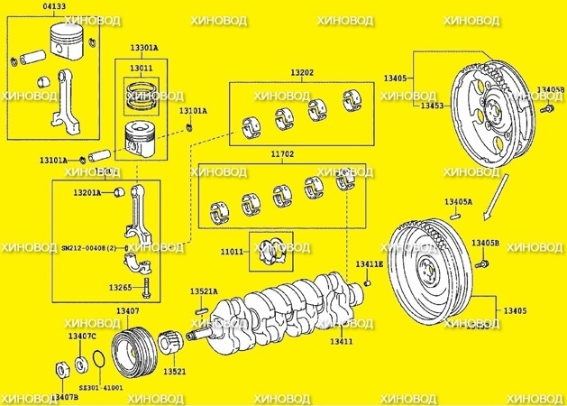
Хиновод — это склад запчастей для ремонта Двигателя Хино (Hino) N04C. Мы подскажем какие запчасти понадобятся для замены. Замена прокладок, головки блока цилиндров. ДВС Хино (Hino) N04C. Установка головки блока. (Замена прокладки ГБЦ) Замена прокладок и установка ГБЦ Как заменить прокладку ГБЦ на двигателе Хино (Hino) N04C
Ремонт ГБЦ N04C — Установка Снятие и установка головки блока цилиндров (ГБЦ). Разборка и сборка головки. ремонт ГБЦ N04C. Как установить ГБЦ? Замена прокладки головки блока цилиндров как снять гбц и клапана Прокладки ГБЦ. Ремонт головки блока Хино (Hino) N04C.
Ремонт головки блока цилиндров Хино (Hino) N04C, ремонт двигателя, ремонт гбц, ремонт блока цилиндров, ремонт головок, ремонт клапанов, ремонт форсунок, ремонт впускного коллектора, ремонт выпускного коллектора.
Руководство по ремонту N04C. Руководство по ремонту, эксплуатации и техническому обслуживанию автомобилей Хино N04C. Инструкция по эксплуатации Содержание: Руководство на русском языке по эксплуатации, техническому обслуживанию и ремонту + каталог расходных запчастей автомобиля Хино 300 N04C
На нашем сайте вы можете купить запчасти двигателя на Хино (Hino) N04C. Мы предлагаем приобрести запчасти Хино от ведущих производителей Японии. Большой выбор запасных частей, низкие цены. Доставка запчастей в любой город России. Запчасти для двигателя, ходовой части и других узлов автомобиля. Для иномарок: оригинальные и качественные аналоги. Цены на сайте Хиновод
N04C-# EngineCOMMON RAIL SYSTEM (CRS)SERVICE MANUAL: OperationIssued : March 2007Revised : December 2009Applicable Vehicle :ManufacturerTOYOTAHINOVehicle NameDYNACOASTERDUTRO00400058EB
Revision HistoryDate2007.03Revision ContentsBasic CRS content omitted, March, 2007 model CRS content added.Items added are as per the following:APPLICABLE VEHICLES AND PRODUCT INFORMATIONMain components and SensorsEXHAUST GAS CONTROL SYSTEM (FEBRUARY 2007, JUNE 2009)Engine ECU External Wiring Diagram and Connector Terminal LayoutENGINE ECU DIAGNOSTIC TROUBLE CODES (DTC)2009.12Basic CRS content omitted, June, 2009 model CRS content added.Items added are as per the following:APPLICABLE VEHICLES AND PRODUCT INFORMATIONINJECTOREngine ECU External Wiring Diagram and Connector Terminal Layout 2009 DENSO CORPORATIONAll rights reserved. This material may not be reproducedor copied, in whole or in part, without the writtenpermission of DENSO Corporation.
Table of ContentsOperation Section1. APPLICABLE VEHICLE AND PRODUCT INFORMATION1.1Introduction . . . . . . . . . . . . . . . . . . . . . . . . . . . . . . . . . . . . . . . . . . . . . . . . . . . . . . . . . . . . . . . . . . . . . . . . . . . . 1-11.2Applicable Vehicles . . . . . . . . . . . . . . . . . . . . . . . . . . . . . . . . . . . . . . . . . . . . . . . . . . . . . . . . . . . . . . . . . . . . . . 1-11.3Applicable Product List . . . . . . . . . . . . . . . . . . . . . . . . . . . . . . . . . . . . . . . . . . . . . . . . . . . . . . . . . . . . . . . . . . . 1-22. SYSTEM OUTLINE2.1Layout of Main Components . . . . . . . . . . . . . . . . . . . . . . . . . . . . . . . . . . . . . . . . . . . . . . . . . . . . . . . . . . . . . . . 1-53. SUPPLY PUMP3.1Outline . . . . . . . . . . . . . . . . . . . . . . . . . . . . . . . . . . . . . . . . . . . . . . . . . . . . . . . . . . . . . . . . . . . . . . . . . . . . . . . . 1-63.2Suction Control Valve (SCV) . . . . . . . . . . . . . . . . . . . . . . . . . . . . . . . . . . . . . . . . . . . . . . . . . . . . . . . . . . . . . . . 1-73.3Fuel Temperature Sensor . . . . . . . . . . . . . . . . . . . . . . . . . . . . . . . . . . . . . . . . . . . . . . . . . . . . . . . . . . . . . . . . 1-104. RAIL4.1Outline . . . . . . . . . . . . . . . . . . . . . . . . . . . . . . . . . . . . . . . . . . . . . . . . . . . . . . . . . . . . . . . . . . . . . . . . . . . . . . . 1-115. INJECTOR5.1Outline . . . . . . . . . . . . . . . . . . . . . . . . . . . . . . . . . . . . . . . . . . . . . . . . . . . . . . . . . . . . . . . . . . . . . . . . . . . . . . . 1-126. CONTROL SYSTEM6.1Control System Diagram . . . . . . . . . . . . . . . . . . . . . . . . . . . . . . . . . . . . . . . . . . . . . . . . . . . . . . . . . . . . . . . . . 1-156.2Engine ECU. . . . . . . . . . . . . . . . . . . . . . . . . . . . . . . . . . . . . . . . . . . . . . . . . . . . . . . . . . . . . . . . . . . . . . . . . . . 1-166.3Electronic Drive Unit (EDU) . . . . . . . . . . . . . . . . . . . . . . . . . . . . . . . . . . . . . . . . . . . . . . . . . . . . . . . . . . . . . . . 1-176.4Sensors . . . . . . . . . . . . . . . . . . . . . . . . . . . . . . . . . . . . . . . . . . . . . . . . . . . . . . . . . . . . . . . . . . . . . . . . . . . . . . 1-187. EXHAUST GAS CONTROL SYSTEM (FEBRUARY 2007, AND JUNE 2009)7.1Outline . . . . . . . . . . . . . . . . . . . . . . . . . . . . . . . . . . . . . . . . . . . . . . . . . . . . . . . . . . . . . . . . . . . . . . . . . . . . . . . 1-237.2E-EGR System . . . . . . . . . . . . . . . . . . . . . . . . . . . . . . . . . . . . . . . . . . . . . . . . . . . . . . . . . . . . . . . . . . . . . . . . 1-237.3DPF System . . . . . . . . . . . . . . . . . . . . . . . . . . . . . . . . . . . . . . . . . . . . . . . . . . . . . . . . . . . . . . . . . . . . . . . . . . 1-248. ENGINE ECU DIAGNOSTIC TROUBLE CODES (DTC)8.1DTC Table . . . . . . . . . . . . . . . . . . . . . . . . . . . . . . . . . . . . . . . . . . . . . . . . . . . . . . . . . . . . . . . . . . . . . . . . . . . . 1-269. CONTROL SYSTEM COMPONENTS9.1Engine ECU External Wiring Diagram. . . . . . . . . . . . . . . . . . . . . . . . . . . . . . . . . . . . . . . . . . . . . . . . . . . . . . . 1-339.2Connector Terminal Layout . . . . . . . . . . . . . . . . . . . . . . . . . . . . . . . . . . . . . . . . . . . . . . . . . . . . . . . . . . . . . . . 1-57
Operation Section1 11. APPLICABLE VEHICLE AND PRODUCT INFORMATION1.1 IntroductionThis manual describes the Common Rail System (CRS) equipped with the NO4C-# engines used in theHINO DUTRO, TOYOTA DYNA (both pickup trucks), as well as the TOYOTA COASTER (bus.)For information on items common to all CRSs, refer to the previously published CRS general additionmanual (Doc ID: 00400076E). [Items common to all CRSs: CRS development process, system control,construction and operation of main components (supply pump, rail, injectors.)]1.2 Applicable VehiclesNovember 2003Vehicle NameEngine ModelDUTRO/DYNAN04C-TFRemarksMarch 2007Vehicle NameEngine ModelDestinationRemarksVehicle power supply voltage: 24 V, EngineECU 12 V spec., with Diesel Particulate FilterN04C-TP(DPF), MTEuropeN04C-TQVehicle power supply voltage: 24 V, MT withDPFN04C-TRDUTRO/DYNAN04C-TSVehicle power supply voltage: 24 V, EngineGeneralECU 12 V spec., MTN04C-TTVehicle power supply voltage: 24 V, EngineN04C-TUECU 12 V spec., ATAustraliaVehicle power supply voltage: 24 V, EngineN04C-TVECU 12 V spec., MTN04C-TWEurope, Hong KongN04C-TQEurope, AustraliaVehicle power supply voltage: 24 V, EngineECU 12 V spec., with DPF, MTVehicle power supply voltage: 24 V, with DPF,MTCOASTERN04C-TYChinaVehicle power supply voltage: 24 V, MTJune 2009Vehicle NameEngine ModelDUTRO/DYNA/COASTERN04C-#Remarks
Operation Section1 21.3 Applicable Product ListNovember 2003Part NameDENSO Part NumberManufacturer Part NumberSupply 0AInjector095000-532#23910-1271AEngine ECU175800-658#89660-37460Electronic Drive Unit (EDU)101310-539#89870-37030Accelerator Pedal Module198800-315#78100-37550Crankshaft Position Sensor029600-136#89410-1630ACamshaft Position Sensor949979-131#89410-1570ACoolant Temperature Sensor071560-011#83420-1250AMass Air Flow (MAF) Meter197400-200#22204-21010Intake Air Temperature Sensor 071500-249#89441-4310AManifold Absolute Pressure(MAP) SensorExhaustGas(EGR) -1080A135000-705#17350-1170ATemperature 265600-060# (IN)265600-053# (OUT)89441-37020 (IN)89441-37030 (OUT)March 2007DENSO PartManufacturerNumberPart Number294000-059#22100-E0060294000-063#22100-E0080 China 3670-E0080095000-652#23670-E0090 General Only095000-655#23670-E0190 China OnlyPart NameSupply PumpRemarksRemarks
Operation SectionPart NameEngineDYNA/ECUDUTROEngineCOASTERECUDENSO PartManufacturerNumberPart Number175800-799#89661-37540N04C-TQ, DPF175800-881#89661-37590N04C-TP, e power supplyvoltage: 24 V, Engine ECU12 V specs.N04C-TUN04C-TQ, N04C-TQ, 7750EGR Valve135000-721#25620-E0010 Without N04C-TR, TS, 00-200#22204-21010265600-053#89425-37021DPF, Upstream of Catalyst265600-054#89425-37031DPF, Downstream of orCrankshaftPositionSensorMAF MeterExhaustGasTemperature supplyvoltage: 12 VVehiclepowervoltage: 24 VN04C-TQDPFpowervoltage: 24 V175800-865#PedalsupplyN04C-TW, DPF89661-36210Acceleratorpowervoltage: 24 V175800-864#EDU1 3supply
Operation Section1 4June 2009DENSO PartManufacturerNumberPart NumberSupply 10095000-848#23670-E0420 24 V use095000-847#23670-E0410 12V 0-37030198800-309#78120-35460DUTRO right-hand driver vehicles198800-326#78100-37820DUTRO left-hand driver vehicles198300-815#89281-26030DYNA, A029600-136#89410-1630AIntake Air Temperature 072800-052#89424-E0060Part NameInjectorEngine sorEGR rSensorMAP 7030104990-102#89480-37010Remarks
Operation Section2. SYSTEM OUTLINE2.1 Layout of Main Components1 5
1 6Operation Section3. SUPPLY PUMP3.1 OutlineThe November 2003, and June 2009 model supply pumps are equipped with an SV1 type Suction ControlValve (SCV). The March 2007 supply pump is equipped with an SV2 type SCV. Additionally, supply pumpsin the part number series 294000-059# are equipped with the SV1 type SCV as of June 2009. Supply pumpsin the part number series 294000-063# are equipped with the SV1 type SCV as of October 2007.(1) November 2003 (294000-019#) , March 2007 (294000-063#*) and June 2009 (294000-059#)* : Beginning from October 2007(2) March 2007 (294000-059#, -063#)
Operation Section3.2 Suction Control Valve (SCV)(1) November 2003 (294000-019#)The supply pumps in the part number series above are equipped with a conventional, normally open type SCV.Operation Concept DiagramOperation1 7
1 8Operation Section(2) March 2007 (294000-059#, -063#)The supply pumps in the part number series above are equipped with a compact, normally closed SCV.Operation Concept DiagramOperation
Operation Section1 9(3) March 2007 (294000-063#*) and November 2009 (294000-059#)The supply pumps in the part number series above are equipped with a conventional, normally closedtype SCV* : Beginning from October 2007Operation Concept DiagramOperation
1 10Operation Section3.3 Fuel Temperature SensorA conventional sensor is used with the NO4C-# engine CRS. Sensor resistance values in relation to fueltemperature are provided below.
Operation Section1 114. RAIL4.1 OutlineRails in the part number series 095440-049# have a flow damper to suppress fuel pulsations.Since rails in the part number series 095440-098# have a built-in function to suppress fuel pulsations, thereis no flow damper.(1) November 2003 (Rail: 095440-049#)(2) March 2007, and June 2009 (Rail: 095440-098#)
1 12Operation Section5. INJECTOR5.1 OutlineThe CRS detailed herein uses solenoid injectors with QR codes.The injectors used in the June 2009 model CRS were designed to show improved responsiveness, as wellas to increase resistance against foreign material adherence to the nozzle.(1) November 2003 (Injector: 095000-532#)
Operation Section(2) March 2007 (Injector: 095000-651#, -652#, -655#)1 13
1 14Operation Section(3) June 2009 (Injector: 095000-847#, -848#)
Operation Section6. CONTROL SYSTEM6.1 Control System Diagram1 15
1 16Operation Section6.2 Engine ECUGeneral export vehicles for Europe, Oceania, and Asia use 12 V specification engine ECUs in relation tothe 24 V vehicle power supply (battery voltage). Accordingly, in the event that service such as repairs arenecessary, always verify the engine ECU specifications. To verify the specifications, look behind thepassenger seat back and check the engine ECU case, as well as whether or not there is a DC-DC converter. ATTENTION When performing checks, do not apply vehicle power supply voltage to the engine ECU. If thevehicle power supply voltage (24 V) is applied to a 12 V specification engine ECU, the ECU may bedamaged.The figure below is an external view of the engine ECU. For the connector pin layout and external wiringdiagram: Refer to [Connector Terminal Layout] on P1-57.
Operation Section1 176.3 Electronic Drive Unit (EDU)A conventional EDU is used with the NO4C-# engine CRS.(1) OperationA high-voltage generating device converts the battery voltage into high voltage. The engine ECU sends signals toterminals B through E of the EDU in accordance with the signals from each sensor. Upon receiving these signals, theEDU outputs signals to the injectors from terminals K through N. At this time, terminal F outputs the IJf injectionverification signal to the ECU.External Wiring Diagram
1 18Operation Section6.4 Sensors(1) Crankshaft position sensor and camshaft position sensorConventional sensors are used as the crankshaft position sensor and camshaft position sensor. The crankshaftposition sensor is a Magnetic Pick Up (MPU) type sensor, while the camshaft position sensor is a MagneticResistance Element (MRE) type.
Operation Section(2) Accelerator position sensor and accelerator pedal moduleA conventional hall element type sensor is used as the accelerator position sensor.Accelerator Position Sensor: DYNA, COASTER1 19
1 20Operation SectionAccelerator Pedal Module: DUTRO
Operation Section1 21(3) Manifold Absolute Pressure (MAP) sensorThe MAP sensor is used in the NO4C-TF engine. Sensor output voltage values in relation to absolute pressure areprovided below.(4) Coolant temperature sensorThe coolant temperature sensor is used in the NO4C-TF engine. Sensor resistance values in relation to coolanttemperature are provided below.
1 22Operation Section(5) Mass Air Flow (MAF) meterA conventional sensor is used with the NO4C-# engine CRS.OperationWhen a heating element (heating coil) is placed in the air passage, the air absorbs heat and cools the heatingelement. For this reason, the resistance value of the heating element decreases, and the current increases. As theintake air volume increases, the cooling temperature of the heating element also increases. The hot-wire type airflowmeter utilizes the changes in the heating element.One portion of the intake air passes by the heating element, and the temperature of the heating element resistorchanges in accordance with the intake air volume. The control circuit is used to ensure the temperature of the heatingelement resistor is always constant. In other words, since the heating element becomes cooler as the airflow volumeincreases, it is necessary to heat the element by increasing current flow through the resistor. This change in currentis converted into voltage by the control circuit IC.However, even if the intake air volume is constant, the temperature of the heating element resistor changes accordingto the intake air temperature. These changes result in errors when detecting the intake air volume. To correct theseerrors, an additional intake air temperature compensator resistor (air thermometer) is used.
Operation Section1 237. EXHAUST GAS CONTROL SYSTEM (FEBRUARY 2007, ANDJUNE 2009)7.1 OutlineBoth an Electric-Exhaust Gas Recirculation (E-EGR) and a Diesel Particulate Filter (DPF) system are usedto comply with Euro 4 emission regulations. The EGR valve, exhaust gas temperature sensor, anddifferential pressure sensor are made by DENSO.7.2 E-EGR SystemThe E-EGR system is an electronically controlled EGR system. The EGR system reduces NOx by loweringthe combustion temperature through re-circulating a portion of the exhaust gas to the intake manifold. Sincethis system may also reduce engine output and decrease drivability, the EGR volume is controlledelectronically to an optimum level in accordance with driving conditions.Both the electronically controlled EGR system and a high-capacity multipass system EGR cooler are used.Engine performance has been increased through enabling high-volume exhaust gas recirculation.A linear solenoid type valve is used as the actuator in the EGR valve. Simultaneous PM and NOx reductionhave been achieved by increasing EGR quantity adjustment precision.An EGR valve lift sensor is also used. The EGR valve opening is fed back to the engine control computerto enable optimal EGR control.(1) Construction and operationTo improve EGR exhaust gas purification performance, feedback control is performed using the EGR valve position.Oxygen concentration in the intake air (which changes according to EGR) is controlled to a target value in accordancewith the engine state (engine speed, rising pressure, part temperatures, load and intake air volume.)To expand the EGR range, the lift sensor installed on the EGR valve performs feedback control of theactual EGR quantity in relation to the pre-set target EGR quantity. Feedback control is based on the intakerestriction position and the variable nozzle turbo position.
1 24Operation Section7.3 DPF SystemA conventional DPF system is used with the NO4C-# engine CRS.
Operation Section1 25(1) Exhaust gas temperature sensorA conventional sensor is used as the exhaust gas temperature sensor. Sensor resistance values in relation to exhaustgas temperature are provided below.(2) Differential pressure sensorA conventional sensor is used as the differential pressure sensor. Sensor output voltage values in relation to exhaustgas differential pressure are provided below.
Operation Section1 268. ENGINE ECU DIAGNOSTIC TROUBLE CODES (DTC)8.1 DTC TableThe following are Diagnostic Trouble Code (DTC) tables for November 2003, and March 2007 vehicles. The»November 2003″ DTC table is for conventional N04C-TF engines. The «March 2007» DTC table is for theN04C-TP, Q, R, S, T, U, V, and W engines.(1) November 2003*1 : TCCS is the name designated by TOYOTA for DTCs resulting from the Malfunction Indicator Light(MIL). For details, refer to the CRS General Edition Manual (00400076E.)*2 : The «A» in «A#» for TCCS represents a «10».DTCSAEDetectionTCCS*1TripLampOutputDetection Item(CE)P0030,P0031,211A/F sensor (B1S1)271A/F sensor (B1S2)P0087491Rail pressure abnormality (fixed output)P0088781Suction Control Valve (SCV) abnormality (high-pressure in rail)P0093781Fuel leak abnormality231311Mass Air Flow (MAF) meter351Manifold Absolute Pressure (MAP) sensor241Intake air temperature 38P0095,P0097,P0098Intake air temperature sensor No. 2 (post-turbo intake airtemperature 12,P0113
Operation SectionDTCSAEDetectionTCCS*1Trip1 27LampOutputDetection Item(CE)P0115,P0117,221Coolant temperature sensor411Accelerator position sensor391Abnormally high fuel temperature391Fuel temperature sensor491Rail pressure sensor with back-up sensorP0191491Rail pressure sensor with back-up sensor (out- of-range)P0200971EDU abnormality (engine diagnostic)P0234341VN turbo abnormality (closed-side abnormality)P0263781Injector abnormality (FCCB abnormality) (No. 1 cylinder)P0266781Injector abnormality (FCCB abnormality) (No. 2 cylinder)P0269781Injector abnormality (FCCB abnormality) (No. 3 cylinder)P0272781Injector abnormality (FCCB abnormality) (No. 4 cylinder)P0299341VN turbo abnormality (open-side abnormality)131P0335121Crankshaft position sensor (open circuit)P0339131Crankshaft position sensor (NE power flicker)P0340121Crankshaft position sensor (open circuit/power flicker)P0340121Camshaft position sensor (during start-up)P0400711Exhaust Gas Recirculation (EGR) flow malfunctionP0400711EGR valve961EGR lift sensorP0488151Intake restriction motor control systemP0500421Vehicle speed sensor (MT)P0504511Stop light switchP0607891CPU abnormalityP0627781Pump abnormality (open/short circuit)P1133001Exterior accelerator position No. 1 sensor highP1143191Throttle knob 190,P0192,P0193P0335P0405,P0406Crankshaft position sensor (open circuit/phase difference/powerflicker)
Operation Section1 28DTCDetectionTripLampOutputDetection ItemSAETCCS*1P1229781Pump valve abnormalityP1238782Injector injection abnormalityP
This manual describes the Common Rail System (CRS) equipped with the NO4C-# engines used in the HINO DUTRO, TOYOTA DYNA (both pickup trucks), as well as the TOYOTA COASTER (bus.) For information on items common to all CRSs, refer to the previously published CRS general addition
![]()
Diesel Injection Pump
SERVICE MANUAL
Common Rail System for HINO Dutro / TOYOTA Dyna N04C-T# Type Engine
OPERATION
November, 2003
00400058E
|
TABLE OF CONTENTS |
|||
|
1. |
Product Application List . . . . . . . . . . . . . . . . . . . . . . . . . . . . . . . . . . . . . . . . . . . . . . . . . . . . . . . . . . . . . . . . . . . . . . . . . . . . . . . . |
1 |
|
|
1-1. |
Vehicle Specifications . . . . . . . . . . . . . . . . . . . . . . . . . . . . . . . . . . . . . . . . . . . . . . . . . . . . . . . . . . . . . . . . . . . . . . . . . . . . . . |
1 |
|
|
1-2. |
Component Part Numbers . . . . . . . . . . . . . . . . . . . . . . . . . . . . . . . . . . . . . . . . . . . . . . . . . . . . . . . . . . . . . . . . . . . . . . . . . . . |
1 |
|
|
2. |
Common Rail System Outline . . . . . . . . . . . . . . . . . . . . . . . . . . . . . . . . . . . . . . . . . . . . . . . . . . . . . . . . . . . . . . . . . . . . . . . . . . . . |
2 |
|
|
2-1. |
Background to Development . . . . . . . . . . . . . . . . . . . . . . . . . . . . . . . . . . . . . . . . . . . . . . . . . . . . . . . . . . . . . . . . . . . . . . . . |
2 |
|
|
2-2. |
System Characteristics . . . . . . . . . . . . . . . . . . . . . . . . . . . . . . . . . . . . . . . . . . . . . . . . . . . . . . . . . . . . . . . . . . . . . . . . . . . . . |
2 |
|
|
2-3. Comparison to The Conventional System . . . . . . . . . . . . . . . . . . . . . . . . . . . . . . . . . . . . . . . . . . . . . . . . . . . . . . . . . . . . . . |
3 |
||
|
3. |
Outline of TOYOTA / HINO Small Truck Common Rail System . . . . . . . . . . . . . . . . . . . . . . . . . . . . . . . . . . . . . . . . . . . . . . . . |
4 |
|
|
3-1. |
Main System Components . . . . . . . . . . . . . . . . . . . . . . . . . . . . . . . . . . . . . . . . . . . . . . . . . . . . . . . . . . . . . . . . . . . . . . . . . . |
4 |
|
|
3-2. Outline of Composition and Operation . . . . . . . . . . . . . . . . . . . . . . . . . . . . . . . . . . . . . . . . . . . . . . . . . . . . . . . . . . . . . . . . |
5 |
||
|
3-3. Fuel System and Control System . . . . . . . . . . . . . . . . . . . . . . . . . . . . . . . . . . . . . . . . . . . . . . . . . . . . . . . . . . . . . . . . . . . . . |
6 |
||
|
4. |
Description of Main Components . . . . . . . . . . . . . . . . . . . . . . . . . . . . . . . . . . . . . . . . . . . . . . . . . . . . . . . . . . . . . . . . . . . . . . . . . |
7 |
|
|
4-1. |
Supply Pump (HP3) . . . . . . . . . . . . . . . . . . . . . . . . . . . . . . . . . . . . . . . . . . . . . . . . . . . . . . . . . . . . . . . . . . . . . . . . . . . . . . . . |
7 |
|
|
4-2. |
Rail . . . . . . . . . . . . . . . . . . . . . . . . . . . . . . . . . . . . . . . . . . . . . . . . . . . . . . . . . . . . . . . . . . . . . . . . . . . . . . . . . . . . . . . . . . . . . |
14 |
|
|
4-3. |
Injector . . . . . . . . . . . . . . . . . . . . . . . . . . . . . . . . . . . . . . . . . . . . . . . . . . . . . . . . . . . . . . . . . . . . . . . . . . . . . . . . . . . . . . . . . |
16 |
|
|
4-4. Engine ECU (Electronic Control Unit) . . . . . . . . . . . . . . . . . . . . . . . . . . . . . . . . . . . . . . . . . . . . . . . . . . . . . . . . . . . . . . . . |
19 |
||
|
4-5. EDU (Electronic Driving Unit) . . . . . . . . . . . . . . . . . . . . . . . . . . . . . . . . . . . . . . . . . . . . . . . . . . . . . . . . . . . . . . . . . . . . . . . |
19 |
||
|
5. |
Description of Control System Components . . . . . . . . . . . . . . . . . . . . . . . . . . . . . . . . . . . . . . . . . . . . . . . . . . . . . . . . . . . . . . |
20 |
|
|
5-1. |
Block Diagram . . . . . . . . . . . . . . . . . . . . . . . . . . . . . . . . . . . . . . . . . . . . . . . . . . . . . . . . . . . . . . . . . . . . . . . . . . . . . . . . . . . |
20 |
|
|
5-2. |
Description of Sensors . . . . . . . . . . . . . . . . . . . . . . . . . . . . . . . . . . . . . . . . . . . . . . . . . . . . . . . . . . . . . . . . . . . . . . . . . . . . |
21 |
|
|
6. |
Various Types of Controls . . . . . . . . . . . . . . . . . . . . . . . . . . . . . . . . . . . . . . . . . . . . . . . . . . . . . . . . . . . . . . . . . . . . . . . . . . . . . . |
26 |
|
|
6-1. Common Rail System Outline . . . . . . . . . . . . . . . . . . . . . . . . . . . . . . . . . . . . . . . . . . . . . . . . . . . . . . . . . . . . . . . . . . . . . . . |
26 |
||
|
6-2. Fuel Injection Quantity Control . . . . . . . . . . . . . . . . . . . . . . . . . . . . . . . . . . . . . . . . . . . . . . . . . . . . . . . . . . . . . . . . . . . . . . |
27 |
||
|
6-3. Fuel Injection Timing Control . . . . . . . . . . . . . . . . . . . . . . . . . . . . . . . . . . . . . . . . . . . . . . . . . . . . . . . . . . . . . . . . . . . . . . . |
30 |
||
|
6-4. Fuel Injection Rate Control . . . . . . . . . . . . . . . . . . . . . . . . . . . . . . . . . . . . . . . . . . . . . . . . . . . . . . . . . . . . . . . . . . . . . . . . . |
31 |
||
|
6-5. Fuel Injection Pressure Control . . . . . . . . . . . . . . . . . . . . . . . . . . . . . . . . . . . . . . . . . . . . . . . . . . . . . . . . . . . . . . . . . . . . . |
31 |
||
|
7. |
Other (ECU Related) . . . . . . . . . . . . . . . . . . . . . . . . . . . . . . . . . . . . . . . . . . . . . . . . . . . . . . . . . . . . . . . . . . . . . . . . . . . . . . . . . . |
32 |
|
|
7-1. ECU External Wiring and Terminal Layout . . . . . . . . . . . . . . . . . . . . . . . . . . . . . . . . . . . . . . . . . . . . . . . . . . . . . . . . . . . . |
32 |
||
|
7-2. |
Diagnostic Trouble Code . . . . . . . . . . . . . . . . . . . . . . . . . . . . . . . . . . . . . . . . . . . . . . . . . . . . . . . . . . . . . . . . . . . . . . . . . . . |
38 |
|
1. |
Product Application List |
|||
|
1-1. |
Vehicle Specifications |
|||
|
Vehicle Name |
Engine Model |
Exhaust Volume |
||
|
HINO DUTRO / TOYOTA DYNA |
N04C-TF |
4.0L |
||
1-2. Component Part Numbers |
||||
|
Product Name |
HINO Part Number |
DENSO Part Number |
||
|
Supply Pump |
22730-1261B |
294000-0191 |
||
|
Rail |
22760-1170A |
095440-0490 |
||
|
Injector |
23910-1271A |
095000-5321 |
||
|
Engine ECU |
89660-37460 |
101758-6580 |
||
|
EDU |
89870-37030 |
101310-5391 |
||
|
APM (Accelerator Pedal Module) |
78100-37550 |
198800-3150 |
||
|
NE Sensor |
89411-1630A |
029600-1361 |
||
|
TDC Sensor |
89410-1570A |
949979-1310 |
||
|
Coolant Temperature Sensor |
83420-1250A |
071560-0110 |
||
|
AFM (Mass Airflow Meter) |
22204-21010 |
197400-2000 |
||
|
Intake Air Temperature Sensor |
89441-4310A |
071500-2490 |
||
|
Turbo Pressure Sensor |
89390-1080A |
079800-5890 |
||
|
EGR-V |
17350-1170A |
135000-7051 |
||
|
Exhaust Gas Temperature Sensor |
89441-37020 (IN) |
265600-0600 (IN) |
||
|
89441-37030 (OUT) |
265600-0530 (OUT) |
|||
-1-

2. Common Rail System Outline
2-1. Background to Development
•The common rail system was developed primarily to cope with exhaust gas regulations for diesel engines, and is a diesel injection control system with the following aims:
•To further improve fuel economy;
•To reduce noise;
•To achieve high power output.
2-2. System Characteristics
•The common rail system uses a type of accumulation chamber called a rail to store pressurized fuel, and injectors that contain electronically controlled solenoid valves to inject the pressurized fuel into the cylinders. Because the engine ECU controls the injection system (injection pressure, injection rate, and injection timing), the injection system is independent, and thus unaffected by the engine speed or load. This ensures a stable injection pressure at all times, particularly in the low engine speed range, and dramatically decreases the amount of black smoke ordinarily emitted by a diesel engine during start-up and acceleration. As a result, exhaust gas emissions are cleaner and reduced, and higher power output is achieved.
A.Injection Pressure Control
•Enables high-pressure injection even at low engine speeds.
•Optimizes control to minimize particulate matter and NOx emissions.
B.Injection Timing Control
•Enables finely tuned optimized control in accordance with driving conditions.
C.Injection Rate Control
•Pilot injection control injects a small amount of fuel before the main injection.
|
Common Rail System |
||||||||||
|
Injection Pressure Control |
Injection Timing Control |
Injection Rate Control |
||||||||
|
Optimization, High Pressurization |
Optimization |
Rate |
Pilot |
After-Injection |
||||||
|
Injection |
||||||||||
|
Post-Injection |
||||||||||
|
Injection Pressure |
Common Rail System |
Common Rail |
Injection |
Main |
||||||
|
System |
||||||||||
|
Injection |
||||||||||
|
Particulate |
||||||||||
|
NOx |
Crankshaft Angle |
|||||||||
|
Injection Quantity Control |
||||||||||
|
Conventional |
Conventional |
Cylinder Injection |
||||||||
|
Quantity Correction |
||||||||||
|
Pump |
TimingInjection |
|||||||||
|
Pump |
||||||||||
|
Speed |
Injection Pressure |
Speed |
Speed |
|||||||
|
1 |
3 |
4 |
2 |
|||||||
|
Q000518E |
||||||||||
|
-2- |
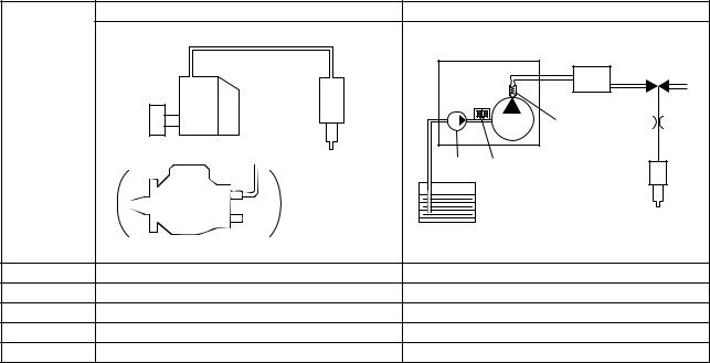
2-3. Comparison to The Conventional System |
||||
|
In-Line & VE Pumps |
Common Rail System |
|||
|
High-Pressure Pipe |
||||
|
Momentary High Pressure |
Supply |
Rail |
||
|
Timer |
Pump |
|||
|
Nozzle |
Normally High Pressure |
|||
|
Governor |
||||
|
System |
Delivery Valve |
|||
|
In-Line Pump |
||||
|
Feed |
SCV (Suction Control Valve) |
|||
|
Pump |
||||
|
Injector |
||||
|
Fuel Tank |
||||
|
VE Pump |
||||
|
Injection Quantity Control |
Pump (Governor) |
Engine ECU, Injector (TWV)*1 |
||
|
Injection Timing Control |
Pump (Governor) |
Engine ECU, Injector (TWV)*1 |
||
|
Rising Pressure |
Pump |
Engine ECU, Supply Pump |
||
|
Distributor |
Pump |
Engine ECU, Rail |
||
|
Injection Pressure Control |
Dependent upon speed and injection quantity |
Engine ECU, Supply Pump (SCV)*2 |
||
|
*1 TWV: Two Way Valve |
||||
|
*2 SCV: Suction Control Valve |
||||
|
Q000387E |
-3-
3. Outline of TOYOTA / HINO Small Truck Common Rail System
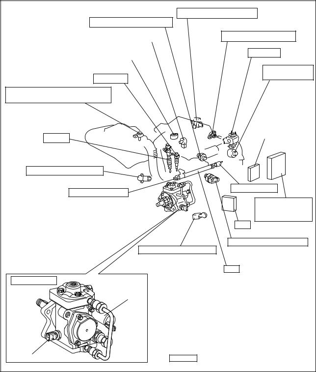
3-1. Main System Components
|
Accelerator Position Sensor |
|
|
Intake Air Temperature Sensor |
|
|
Variable Nozzle Type Turbo Opening Sensor |
Intake Air Pressure Sensor |
|
Variable Nozzle Type Turbo Motor |
EGR Valve |
|
Intake Restriction |
|
|
Glow Plug |
Step Motor |
|
Airflow Meter (With Integrated Ambient |
|
|
Air Temperature Sensor) |
|
|
Variable Nozzle |
|
|
Injector |
Controller |
|
Crankshaft Position Sensor |
|
|
Rail Pressure Sensor |
Pressure Limiter |
|
Engine ECU (With |
|
|
Built-In Atmospheric |
|
|
Pressure Sensor) |
|
|
EDU |
|
|
Coolant Temperature Sensor |
|
|
Cylinder Recognition Sensor |
|
|
Rail |
|
|
Supply Pump |
|
|
SCV |
|
|
Fuel Temperature Sensor |
Items are DENSO products |
|
Q000569E |
|
|
-4- |
3-2. Outline of Composition and Operation A. Composition
The common rail system consists primarily of a supply pump, rail, injectors, and engine ECU.
Fuel Temperature
Vehicle Speed 
Accelerator Opening 
Intake Air Pressure
Intake Air Temperature  Engine ECU
Coolant Temperature 
Crankshaft Position 
Cylinder Recognition Signal 
|
Intake Airflow Rate |
|||
|
Rail |
Pressure |
Injector |
|
|
Limiter |
|||
|
Rail |
|||
|
Pressure Sensor |
Fuel Temperature Sensor
|
Supply Pump |
SCV (Suction |
Fuel Tank |
|
|
Control Valve) |
|||
Q000144E
B. Operation
a.Supply Pump (HP3)
The supply pump draws fuel from the fuel tank, and pumps the high pressure fuel to the rail. The quantity of fuel discharged from the supply pump controls the pressure in the rail. The SCV (Suction Control Valve) in the supply pump effects this control in accordance with commands received from the engine ECU.
b.Rail
The rail is mounted between the supply pump and the injector, and stores the high-pressure fuel.
c.Injector (G2 Type)
This injector replaces the conventional injection nozzle, and achieves optimal injection by effecting control in accordance with signals from the engine ECU. Signals from the engine ECU determine the duration and timing in which current is applied the injector. This in turn, determines the quantity, rate and timing of the fuel that is injected from the injector. QR codes noting the characteristics of each vehicle are inscribed on the injector, and this data is sent to the ECU when the engine ECU or injectors are replaced. This enables software to be adjusted to the mechanical characteristics of each injector.
d.Engine ECU
The engine ECU calculates data received from the sensors to comprehensively control the injection quantity, timing and pressure.
-5-

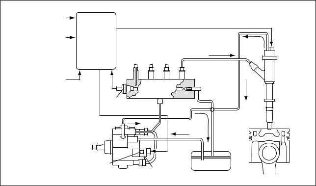
3-3. Fuel System and Control System A. Fuel System
This system comprises the route through which diesel fuel flows from the fuel tank via the rail to the supply pump, and is injected through the injector, as well as the route through which the fuel returns to the tank via the overflow pipe.
B. Control System
In this system, the engine ECU controls the fuel injection system in accordance with signals received from various sensors. The components of this system can be broadly divided into the following three types: (a) sensors; (b) ECU; and (c) actuators.
a.Sensors
Detect the engine and driving conditions, and convert them into electrical signals.
b.Engine ECU
Performs calculations based on the electrical signals received from the sensors, and sends them to the actuators in order to achieve optimal conditions.
c.Actuators
Operate in accordance with electrical signals received from the ECU. Injection system control is undertaken by electronically controlling the actuators. The injection quantity and timing are determined by controlling the duration and timing in which current is applied to the TWV (Two-Way Valve) in the injector. Injection pressure is determined by controlling the SCV (Suction Control Valve) in the supply pump.
|
Sensor |
Actuator |
|||||||
|
Crankshaft Position Sensor NE |
Engine Speed |
|||||||
|
Injector |
||||||||
|
· Injection Quantity Control |
||||||||
|
Cylinder Recognition |
· Injection Timing Control |
|||||||
|
Cylinder Recognition Sensor G |
· Injection Pressure Control |
|||||||
|
Load |
Engine |
|||||||
|
Accelerator Position Sensor |
||||||||
|
ECU |
Supply Pump (SCV) |
|||||||
|
· Fuel Pressure Control |
||||||||
|
Rail Pressure Sensor |
||||||||
|
EGR, Air Intake Control |
||||||||
|
Relay, Light |
||||||||
|
Other Sensors and Switches |
||||||||
|
Q000390E |
||||||||
-6-
4. Description of Main Components
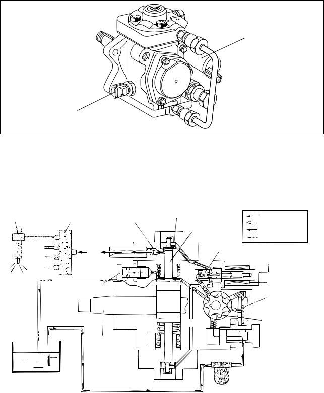
4-1. Supply Pump (HP3)
A.Outline
•The supply pump consists primarily of the pump body (camshaft (eccentric cam), ring cam, and plungers), SCV (Suction Control Valve), fuel temperature sensor, and feed pump.
SCV
Fuel Temperature Sensor
Q000570E
•The two plungers are positioned vertically on the outer ring cam for compactness.
•The engine drives the supply pump at a ratio of 1:1. The supply pump has a built-in feed pump (trochoid type), and draws the fuel from the fuel tank, sending it to the plunger chamber.
•The internal camshaft drives the two plungers, and they pressurize the fuel sent to the plunger chamber and send it to the rail. The quantity of fuel supplied to the rail is controlled by the SCV, using signals from the engine ECU. The SCV is a normally open type (the intake valve opens during de-energization).
|
Injector |
Rail |
Intake Valve |
Intake Pressure |
|||
|
Discharge Valve |
Feed Pressure |
|||||
|
Plunger |
High Pressure |
|||||
|
Return |
||||||
|
Return Spring |
||||||
|
Return |
||||||
|
Fuel Overflow |
SCV |
|||||
|
Regulating Valve |
||||||
|
Feed Pump |
||||||
|
Filter |
||||||
|
Camshaft |
Fuel Inlet |
|||||
|
Fuel Tank |
Intake Fuel Filter |
|||||
|
(With Priming Pump) |
||||||
|
Q000392E |
• The supply pump in the common rail system with DPNR has a fuel cut valve (FCV). The FCV is provided to enable manual shut-off if a fuel leak occurs in the fuel addition valve passage.
-7-
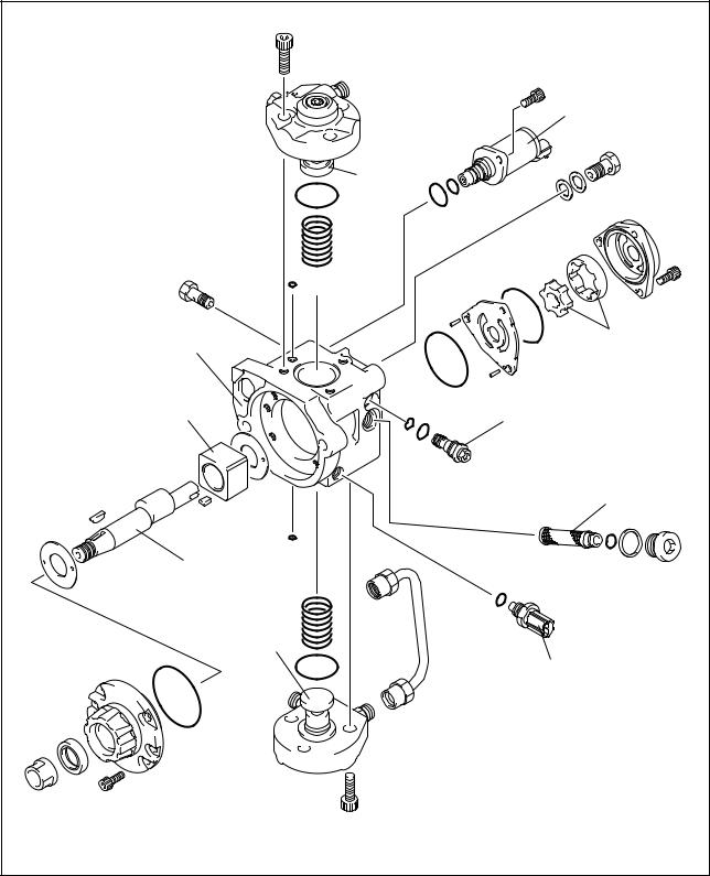
a.Supply Pump Exploded Diagram
|
SCV |
|
|
(Suction Control Valve) |
|
|
Plunger |
|
|
Pump Body |
Feed Pump |
|
Ring Cam |
Regulating Valve |
|
Filter |
|
|
Camshaft |
|
|
Plunger |
|
|
Fuel Temperature Sensor |
|
|
Q000393E |
|
|
-8- |

B. Supply Pump Internal Fuel Flow
Fuel drawn from the fuel tank passes through the route in the supply pump as illustrated, and is fed into the rail.
|
Supply Pump Interior |
|||||||||||||||||||||||
|
Regulating Valve |
|||||||||||||||||||||||
|
Feed Pump |
SCV (Suction Control Valve) |
Discharge Valve |
Rail |
||||||||||||||||||||
|
Overflow |
|||||||||||||||||||||||
|
Intake Valve |
Pumping Portion (Plunger) |
||||||||||||||||||||||
Fuel Tank
Q000394E
C.Construction of Supply Pump
•The eccentric cam is formed on the camshaft and is attached to the ring cam.
Ring Cam
Camshaft
Eccentric Cam
Q000395E
• As the camshaft rotates, the eccentric cam rotates eccentrically, and the ring cam moves up and down while rotating.
Eccentric Cam
Ring Cam
Camshaft
Q000396E
-9-
•The plunger and the suction valve are mounted on top of the ring cam. The feed pump is connected to the rear of the camshaft.
Plunger A
Ring Cam
Feed Pump
Plunger B
QD0728E
D. Supply Pump Operation
As shown in the illustration below, the rotation of the eccentric cam causes the ring cam to push Plunger A upwards. Due to the spring force, Plunger B is pulled in the opposite direction to Plunger A. As a result, Plunger B draws in fuel while Plunger A pumps it to the rail.
Suction Valve Delivery Valve
Plunger A
Eccentric Cam
Ring Cam
SCV
Plunger B
|
Plunger A: Finish Compression |
Plunger A: Begin IntakePlunger |
|
Plunger B: Finish Intake |
B: Begin Compression |
|
Plunger A: Begin Compression |
Plunger A: Finish Intake |
||||||||||||||||||||||||||
|
Plunger B: Begin Intake |
Plunger B: Finish Compression |
QD0707E
-10-
E. Description of Supply Pump Components
a.Feed Pump
The trochoid type feed pump integrated into the supply pump, draws fuel from the fuel tank and feeds it to the two plungers via the fuel filter and the SCV (Suction Control Valve). The feed pump is driven by the camshaft. With the rotation of the inner rotor, the feed pump draws fuel from its suction port and pumps it out through the discharge port. This is done in accordance with the space that increases and decreases with the movement of the outer and inner rotors.
Quantity Decrease
To Quantity Decrease (Fuel Discharge)
Pump Chamber
Outer Rotor
Inner Rotor
Intake Port
|
Discharge |
Quantity Increase |
Quantity Increase |
|
|
Port |
|||
|
From |
(Fuel Intake) |
||
|
Fuel Tank |
QD0708E |
||
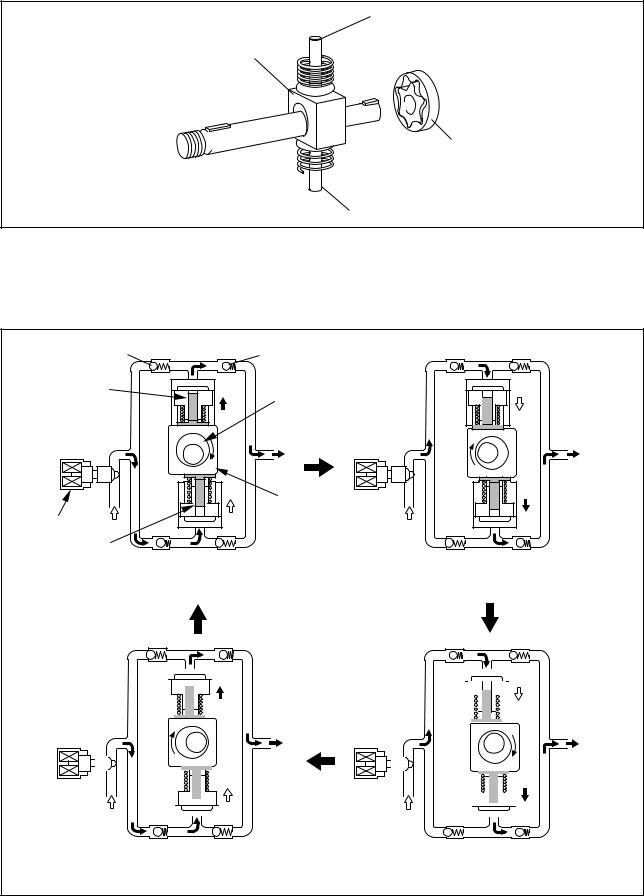
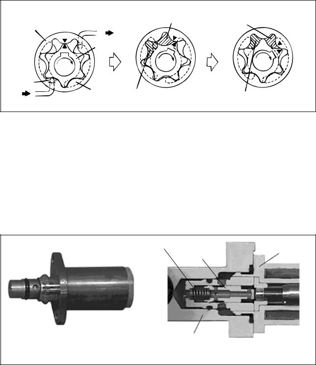
b.SCV (Suction Control Valve: Normally Open Type)
•A linear solenoid type valve has been adopted. The ECU controls the duty ratio (the duration in which current is applied to the SCV), in order to control the quantity of fuel that is supplied to the high-pressure plunger.
•The supply pump drive load decreases because intake fuel quantity is controlled to achieve the target rail pressure.
•When current flows to the SCV, the internal armature moves in accordance with the duty ratio. The fuel quantity is regulated by the cylinder, which moves in connection with the armature to block the fuel passage.
•With the SCV OFF, the return spring pushes the cylinder, completely opening the fuel passage and supplying fuel to the plungers. (Full quantity intake => full quantity discharge.)
•When the SCV is ON, the return spring contracts and closes the fuel passage.
•By turning the SCV ON/OFF, fuel is supplied in an amount corresponding to the drive duty ratio and then discharged by the plungers.
Return Spring
SCV
Cylinder
Pump Body
|
External View |
Cross-Section |
Q000050E
-11-
 Loading…