- Manuals
- Brands
- Isuzu Manuals
- Engine
- 4HK-1
- Manual
-
Bookmarks
Quick Links
Isuzu
4HK-1 and 6HK-1
ENGINE
FUEL SYSTEM
CE APPLICATIONS
Revised 8/29/06
Form Number 5137
1
Related Manuals for Isuzu 4HK-1
Summary of Contents for Isuzu 4HK-1
-
Page 1
Isuzu 4HK-1 and 6HK-1 ENGINE FUEL SYSTEM CE APPLICATIONS Revised 8/29/06 Form Number 5137… -
Page 2
Table Of Contents… -
Page 3
These engines also use an air to air aftercooling intake air system. The air to air intake system ports pressurized air flow between the turbocharger and the intake manifold through an air to air heat exchanger in front of the radiator. The 4HK-1 model has a displacement of 317 cubic inches (in ) or 5193 cubic centimeters (cc). -
Page 4
Isuzu 4HK-1 and 6HK-1 Engine Overview The electronic control system for the Isuzu 4HK-1 and 6HK-1 Engines use input information from a number of sensors and from the Excavator controller to determine the quantity and timing of the fuel delivery to the engine. -
Page 5
Isuzu 6HK1 Common Rail Engine Fuel System Common Fuel Temp Coolant Intake Air Boost Temp Barometric ENG Oil Engine Stop Rail Fuel PSI Sensor Temperature Temp. Sensor Sensor AMB PSI Switch Sensor Sensor Sensor Sensor Boost PSI Crankshaft Camshaft Sensor… -
Page 6
90° on the gear and one reference hole) on the camshaft gear flange surface on the 4HK-1 Engine. Seven through holes (six holes arranged equally every 60° on the gear and one reference hole) on the camshaft gear flange surface on the 6HK-1 Engine. -
Page 7
Isuzu 6HK1 Common Rail Engine Fuel System Common Fuel Temp Coolant Intake Air Boost Temp Barometric ENG Oil Engine Stop Rail Fuel PSI Sensor Temperature Temp. Sensor Sensor AMB PSI Switch Sensor Sensor Sensor Sensor Boost PSI Crankshaft Camshaft Sensor… -
Page 8
Isuzu 4HK-1 and 6HK-1 Engine Overview (continued) Inputs to 81 pin engine harness connector: • The 2 wire intake air temperature (IAT) sensor is installed on intake air tube and detects the temperature of intake air for optimum fuel injection control. -
Page 9
Isuzu 6HK1 Common Rail Engine Fuel System Common Fuel Temp Coolant Intake Air Boost Temp Barometric ENG Oil Engine Stop Rail Fuel PSI Sensor Temperature Temp. Sensor Sensor AMB PSI Switch Sensor Sensor Sensor Sensor Boost PSI Crankshaft Camshaft Sensor… -
Page 10
Isuzu 4HK-1 and 6HK-1 Engine Overview (continued) Inputs to 81 pin engine harness connector: (continued) • The CAN (Controller Area Network) Data Bus Connector transmits communication between the engine controller and the Excavator controller. This connector transmits throttle, idle up/down, work mode, breaker mode, tachometer, instrumentation and fault code information. -
Page 11
Isuzu 6HK1 Common Rail Engine Fuel System Common Fuel Temp Coolant Intake Air Boost Temp Barometric ENG Oil Engine Stop Rail Fuel PSI Sensor Temperature Temp. Sensor Sensor AMB PSI Switch Sensor Sensor Sensor Sensor Boost PSI Crankshaft Camshaft Sensor… -
Page 12
Isuzu 4HK-1 and 6HK-1 Engine Overview (continued) Outputs from 40 pin engine harness connector: (continued) • The injectors are controlled by the engine control module (ECM). The ECM sends a common power supply to injectors 1, 3 and 5. The ECM also sends a common power supply to injectors 2, 4 and 6. -
Page 13
Isuzu 6HK1 Common Rail Engine Fuel System Common Fuel Temp Coolant Intake Air Boost Temp Barometric ENG Oil Engine Stop Rail Fuel PSI Sensor Temperature Temp. Sensor Sensor AMB PSI Switch Sensor Sensor Sensor Sensor Boost PSI Crankshaft Camshaft Sensor… -
Page 14
Isuzu 4HK-1 and 6HK-1 Engine Fuel Schematic Overview Fuel System Hydraulic Function Fuel comes from the tank and typically will go through a prefilter assembly. From the prefilter, the fuel then flows to an electric fuel pump, located in the hydraulic pump compartment. -
Page 16
Isuzu 4HK-1 and 6HK-1 Engine Fuel Schematic Overview The common rail system stores high pressure fuel between the supply pump and the injectors. The common rail also serves as an accumulator to dampen the fuel pulsations from the pump. Flow dampers are located at the outlet of the common rail to the lines to the injectors. -
Page 19
Isuzu 4HK-1 and 6HK-1 Engine Sensor Locations… -
Page 20
Exhaust gas Recirculation (EGR) System Exhaust Gas Recirculation system is abbreviated to EGR system. It recirculates part of exhaust gas into intake manifold to mix an inert gas with intake air. This leads to lower the combustion temperature to limit emissions of nitrogen oxide (NOx). It controls amount of EGR by opening/closing the EGR valve installed between exhaust manifold and intake manifold. -
Page 23: Engine Control System
Engine Control System 42 Installation of ECM Install the ECM in the reverse order of removal. EGR valve position learning is required after replacing the ECM. 1. Turn the key switch to “ON”. 2. Turn the key switch to “OFF”. 3.
-
Page 24
Engine Control System 56 Senser and actuator *Refer at last page.(About wiring diagrams) -
Page 25
57 Engine Control System Circuit diagram (Refer to “Wiring diagrams” for a way to read the diagram.) Main relay circuit TSWG0027… -
Page 26
Engine Control System 58 Starter for safety relay, glow circuit TSWG0068… -
Page 27
59 Engine Control System CAN, GND, DLC circuits TSHK0013… -
Page 28
Engine Control System 60 Injector circuit TSWG0031… -
Page 29
61 Engine Control System SCV circuit TSHK0016… -
Page 30
Engine Control System 62 CKP sensor, fuel temperature sensor, engine coolant temperature sensor, engine oil pressure sensor circuit TSHK0017… -
Page 31
63 Engine Control System Boost temperature sensor, boost pressure sensor circuit TSWG0034… -
Page 32
Engine Control System 64 CMP sensor, common rail pressure sensor, EGR circuit TSHK0018… -
Page 33
65 Engine Control System Memory clear switch, engine stop switch circuit TSWG0038… -
Page 34
This page Is Intentionally Left Blank. -
Page 35
67 Engine Control System TSHK0035… -
Page 36
Engine Control System 68 Terminal Terminal Number Number Boost pressure sensor GND CKP + Boost pressure sensor Vout CKP GND Boost pressure sensor Vcc E112 Terminal Number Terminal Number CMP shield Engine oil pressure sensor GND CMP GND Engine oil pressure sensor Vout CMP + Engine oil pressure sensor Vcc E113… -
Page 37
69 Engine Control System Terminal Terminal Number Number SCV−Lo CKP + SCV−Hi CKP GND Fuel temperature sensor + CKP shield ECT meter CMP + — CMP GND Overheating switch CMP shield ECT + Boost pressure sensor Vcc Terminal Engine oil pressure sensor Vcc Number Engine oil pressure sensor Vout EGR hall sensor U… -
Page 38
Engine Control System 70 Terminal Number — OS−INJ6 signal Injector power supply 2 Injector power supply 1 — OS−INJ4 signal OS−INJ2 signal — (Female connector on injector side) In cylinder head (Female connector on injector side) (Male connector on ECM side) (Male connector on ECM side) TSWG0041… -
Page 39
71 Engine Control System Connector list Connector Face Connector Face E-27 E-75 003-501 #1 injector (Silver) E-29 E-76 003-501 #2 injector (Silver) (Black) E-31 E-80 #3 injector (Silver) (Black) E-33 E-90 003-500 #4 injector (Silver) (Blue) E-35 E-93 #5 injector (Silver) (Gray) E-37 E-98… -
Page 40
Engine Control System 72 Connector Face Connector Face E-114 (Black) (Black) E-161 (Brown) (Gray) E-162 (Dark gray) (Gray) E-163 (Gray) (Black) E-164 (Black) FB-124 H-12 (Black) (Gray) FL-150 H-12 016-500 (Gray) 9 10 11 12 FL-269 H-20 13 14 15 16 17 18 19 20 020-500 003-502… -
Page 41
73 Engine Control System Connector Face Connector Face H-95 12 11 10 9 H-20 (ECM 16 15 14 13 side) 20 19 18 17 020-501 (Gray) H-95 (Injector side) (White) (Gray) H-95 (Injector side) (White) (Gray) H-94 (ECM side) (Gray) H-94 (ECM side) -
Page 42
This page Is Intentionally Left Blank. -
Page 43
103 Trouble Shooting — EXAMPLE From Service Manual Error Code: 0088 Common rail pressure is abnormally high (1st or 2nd stage). TSHK0041 Name 1. Common rail 5. Fuel tank 2. Fuel filter 6. Supply pump 3. Electromagnetic Pump 7. Injector 4. -
Page 44: Trouble Shooting 104
Trouble Shooting 104 Engine control module (ECM) CMP sensor EGR position EGR position EGR position Common rail pressure signal sensor signal sensor signal sensor signal sensor signal 99 E-56 98 E-56 E-56 E-56 E-56 E-56 E-56 E-56 E-56 E-56 E-56 E-56 E-56 H-20…
-
Page 45
105 Trouble Shooting — EXAMPLE From Service Manual Error Code set condition Back-up mode 1st step • L mode fixed. • Rail pressure is more than 185MPa for 5 seconds • Limited injection amount 3 (multi-injection stopped) or more. • Target RP upper limit (80MPa) •… -
Page 46: Trouble Shooting 106
Trouble Shooting 106 Step Action Value Check the fuel return pipe between the supply pump and the fuel tank for breakage, twist, etc. Check for clogging or twisting in the vent hose of the fuel tank. — Check for foreign matter in the fuel tank. If the trouble is detected, repair as required.
-
Page 47
107 Trouble Shooting — EXAMPLE From Service Manual About common rail pressure sensor TSWG0055 Name 1. Sensor ground 2. Sensor signal 3. Sensor power supply Characteristics of common rail pressure sensor (MPa) TSWG0201… -
Page 48
5. 380002726 EMPS/EST ECM Cable 6. 380002728 EMPS/EST RS232 Null Modem Cable Start the Engine Download Tool — Isuzu EMPS The Additional Tools screen provides a button linking the Electronic Service Tool to: • Engine Diagnostic Tool — Isuzu EMPS… -
Page 49: Process Menu
Preliminary ELECTRONIC SERVICE TOOL (EST) Engine Module Programming System (EMPS) — Summary Selecting an EMPS Process Process Menu Select an EMPS operation from the Process Menu Process Menu. • ECM Reflash — Select when the ECM control program is suspected to have ECM Reflash damaged/corrupted files.
-
Page 50
This page Is Intentionally Left Blank.
This manual is also suitable for:
6hk-1
![]()
WORKSHOP MANUAL
727 (N SERIES)
ENGINE CONTROL SYSTEM
(4HK1 ENGINE)
SECTION 1A
International Service & Parts
Tokyo, Japan
N O T I C E
Before using this Workshop Manual to assist you in performing vehicle service and maintenance operations, it is recommended that you carefully read and thoroughly understand the information contained in Section — 0A under the headings “GENERAL REPAIR INSTRUCTIONS” and “HOW TO USE THIS MANUAL”.
All material contained in this Manual is based on the latest product information available at the time of publication.
All rights are reserved to make changes at any time without prior notice.

Engine Control System 1A-1
ENGINE
Engine Control System
CONTENTS
Engine Control System . . . . . . . . . . . . . . . . . . . . 1A-2 Precautions on Service . . . . . . . . . . . . . . . . . . . 1A-2 Function and Operation. . . . . . . . . . . . . . . . . . . 1A-4 Component Layout . . . . . . . . . . . . . . . . . . . . . 1A-20 Circuit diagram . . . . . . . . . . . . . . . . . . . . . . . . 1A-25 Strategy-Based Diagnostics . . . . . . . . . . . . . . 1A-31 Functional Check List . . . . . . . . . . . . . . . . . . . 1A-37 Hearing Diagnostic . . . . . . . . . . . . . . . . . . . . . 1A-37 On-Board Diagnostic (OBD) System Check . . 1A-39 Inactive CHECK ENGINE Lamp (MIL) . . . . . . 1A-41 CHECK ENGINE Lamp (MIL) Remains Active 1A-44 Engine Cranks But Will Not Run . . . . . . . . . . . 1A-46 Diagnosis with Tech 2 Scan Tool. . . . . . . . . . . 1A-48 Diagnostic Chart . . . . . . . . . . . . . . . . . . . . . . . 1A-67 DTC11 — No Signal CKP Sensor . . . . . . . . . . . 1A-73 DTC13 — TCV Fault . . . . . . . . . . . . . . . . . . . . . 1A-75 DTC14 — Pump ROM Fault . . . . . . . . . . . . . . . 1A-78 DTC15 — Pump Cam Sensor (NE Sensor)
Short Break Fault . . . . . . . . . . . . . . . . . . . . . . 1A-80 DTC16 — No Signal from Pump Cam Sensor
(NE Sensor) . . . . . . . . . . . . . . . . . . . . . . . . . . 1A-82 DTC21 — ECT Sensor Fault . . . . . . . . . . . . . . . 1A-84 DCT23 — IAT Sensor Fault. . . . . . . . . . . . . . . . 1A-88 DTC24 — AP Sensor Output Fault . . . . . . . . . . 1A-91 DTC25 — VS Sensor Circuit Fault . . . . . . . . . . 1A-95 DTC31 — Idle Up Volume Fault . . . . . . . . . . . . 1A-98 DTC32 — MAP Sensor Fault . . . . . . . . . . . . . 1A-101 DTC34 — Exhaust Brake Open Wiring Fault . 1A-104 DTC35 — Neutral Switch Signal Fault . . . . . . 1A-106 DTC36 — Clutch Switch Signal Fault
(M/T Vehicle only) . . . . . . . . . . . . . . . . . . . . . 1A-108 DTC41 — FT Sensor Circuit High Voltage . . . 1A-110 DTC51 — Atmospheric Pressure Sensor Fault 1A-113 DTC52 — ECM Internal Fault . . . . . . . . . . . . . 1A-114 DTC53 — Engine Driver Unit Fault . . . . . . . . . 1A-116 DTC55 — Pump Unmatched
(Difference from ECM Specifications) . . . . . . 1A-118 DTC65 — Idle Position Switch Fault . . . . . . . . 1A-120 Symptom Diagnosis Chart . . . . . . . . . . . . . . 1A-122 Hard Starting . . . . . . . . . . . . . . . . . . . . . . . . . 1A-123 Vehicle Speed Variation . . . . . . . . . . . . . . . . 1A-127 Lack Power or Faulty Response . . . . . . . . . . 1A-130 Unstable Idling . . . . . . . . . . . . . . . . . . . . . . . 1A-134 Engine Not Stall . . . . . . . . . . . . . . . . . . . . . . 1A-137 Starter Motor does Not Run . . . . . . . . . . . . . 1A-139 Quick On Start (QOS) System does Not
Operate . . . . . . . . . . . . . . . . . . . . . . . . . . . . . 1A-142 Excessive Black Smoke in Exhaust Gas. . . . 1A-144 Excessive White Smoke in Exhaust Gas . . . 1A-147 Noisy Engine . . . . . . . . . . . . . . . . . . . . . . . . . 1A-149 Nasty Smell. . . . . . . . . . . . . . . . . . . . . . . . . . 1A-152
Poor Fuel Economy. . . . . . . . . . . . . . . . . . . . 1A-155
Excessive Engine Oil Consumption . . . . . . . 1A-159
Large Engine Vibration . . . . . . . . . . . . . . . . . 1A-161
Special Tools . . . . . . . . . . . . . . . . . . . . . . . . . 1A-164
Wiring Harness Repair: Shielded Cable. . . . . . 1A-165
Removal Procedure . . . . . . . . . . . . . . . . . . . 1A-165
Installation Procedure . . . . . . . . . . . . . . . . . . 1A-165
Twisted Leads . . . . . . . . . . . . . . . . . . . . . . . . . 1A-166
Removal Procedure . . . . . . . . . . . . . . . . . . . 1A-166
Installation Procedure . . . . . . . . . . . . . . . . . . 1A-166
Weather-Pack Connector . . . . . . . . . . . . . . . . . 1A-168
Removal Procedure . . . . . . . . . . . . . . . . . . . 1A-168
Installation Procedure . . . . . . . . . . . . . . . . . . 1A-168
Special Tools . . . . . . . . . . . . . . . . . . . . . . . . . 1A-169
Com-Pack III. . . . . . . . . . . . . . . . . . . . . . . . . . . 1A-170
General Information . . . . . . . . . . . . . . . . . . . 1A-170
Metri-Pack . . . . . . . . . . . . . . . . . . . . . . . . . . . . 1A-171
Removal Procedure . . . . . . . . . . . . . . . . . . . 1A-171
Installation Procedure . . . . . . . . . . . . . . . . . . 1A-171
Special Tools . . . . . . . . . . . . . . . . . . . . . . . . . 1A-171

1A-2 Engine Control System
Engine Control System
Precautions on Service
Circuit Test Tools
Unless otherwise specified in diagnostic procedures, do not use Test Light to diagnose the powertrain electrical system. When diagnostic procedures need probe connector, use Connector Test Adapter Kit 5- 8840-0385-0.
On-Market Electrical Equipment and Vacuum Devices
On-market electrical equipment and vacuum devices refer to those components that will be installed to vehicles after shipment from manufacturing plants. Be careful that installation of these components is not considered during the process of vehicle design.
CAUTION:
Do not install on-market vacuum devices to vehicles.
CAUTION:
Connect on-market electrical equipment, as well as its power supplies and grounds, to the circuits isolated from the electronic control system.
The on-market electrical equipment, even when installed to vehicles in normal manner, may bring functional troubles to the electronic control system. Affected devices include those not connected to the vehicle electrical equipment system, for example, mobile phones or radios. Therefore, when you intend to diagnose the powertrain, check such the on-market electrical equipment has not been installed to the vehicle and, if installed, remove it. If faults still occur even after removal of on-market electrical equipment, diagnose the vehicle according to normal procedures.
List of Abbreviations
Damage by Electrostatic Discharge
Electronic components used in the electronic control system are designed to work at very low voltages and, for this reason, they are susceptible to damage by electrostatic discharge and some types of electronic components may be damaged even by the static electricity of less than 100 V that is usually not sensed by persons. Persons’ sensitivity level is 4,000 V. Persons are electrostatically charged in various ways and the most typical electrification sources are friction and induction. Shown below are examples.
•Electrification by friction occurs when a person slides on the seat in the vehicle.
•Electrification by induction occurs when a person with insulating shoes is standing near a highly electrifiable substance and touches a ground momentarily. Electric charges with the same polarity flow out and resultantly the person is charged at high opposite polarity. Since static electric charges cause damages, it is important when you handle or test electronic components.
CAUTION:
To prevent damages by electrostatic discharge, follow the guidelines shown below.
•Do not touch ECM connector pins as well as electronic components soldered to the ECM circuit board.
•Do not unpack each replacement component until preparations are completed for the component.
•Before taking out a component from the package, connect the package to the normal grounding line of the vehicle.
•When you intend to slide on the seat, change the posture from standing to sitting, or walk by a certain distance to handle a component, touch an appropriate grounding material.
|
Abbreviation |
Original form |
Meaning in this manual |
|
A/C |
Air Conditioner |
Air conditioning units (cooler, heater, etc.) |
|
AP |
Accelerate Position |
Depressing stroke of accelerator pedal |
|
CKP |
Crankshaft Position |
Rotating reference signal of crankshaft |
|
CMP |
Camshaft Position |
Rotating reference signal of pump camshaft |
|
DLC |
Data Link Connector |
DLC connector (Tech 2 communication connector) |
|
DTC |
Diagnosis Trouble Code |
DTC code |
|
DVM |
Digital Volt Meter |
Special service tool (part No. 5-8840-0366-0) |
|
ECT |
Engine Coolant Temperature |
Coolant temperature |
|
ECM |
Engine Control Modulle |
Engine control computer |
|
EDU |
Engine Driver Unit |
Fuel pump spill valve drive unit |

|
Engine Control System 1A-3 |
||
|
Abbreviation |
Original form |
Meaning in this manual |
|
EGR |
Exhaust Gas Recirculation |
Exhaust gas recirculation |
|
ISM |
Intake Step Motor |
Intake throttle valve drive motor |
|
ITP |
Intake Throttle Position |
Intake throttle valve opening |
|
MIL |
Malfunction Indicator Lamp |
CHECK ENGINE Lamp |
|
SPV |
Spill Control Valve |
Valve for high pressure circuit in the fuel pump |
|
SW |
Switch |
|
|
TCV |
Timing Control Valve |
Injection timing control valve in the fuel pump |
|
Key SW |
Key switch |
Starter switch |
Wire Color
All wiring harnesses are identified using colored jacket. The wiring harness used for the main circuit in an electrical system is identified with single color while the wiring harness used for the sub-circuit is identified with color stripe. The following rule is used in each wiring diagram to indicate size and color of a wiring harness.
eg. : 0.5 GRN / RED
1
2
3
LNW21ASH000101-X
|
Legend |
|||||
|
1. |
Red (stripe color) |
||||
|
2. |
Green (base color) |
||||
|
3. |
Harness size (0.5 mm2) |
||||
|
Symbol |
Color |
Symbol |
Color |
||
|
B |
Black |
BR |
Brown |
||
|
W |
White |
LG |
Light green |
||
|
R |
Red |
GR |
Gray |
||
|
G |
Green |
P |
Pink |
||
|
Y |
Yellow |
LB |
Light blue |
||
|
L |
Blue |
V |
Violet |
||
|
O |
Orange |
||||
1A-4 Engine Control System
Function and Operation
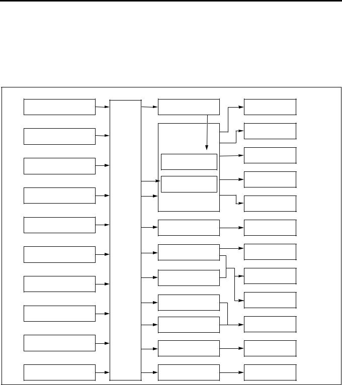
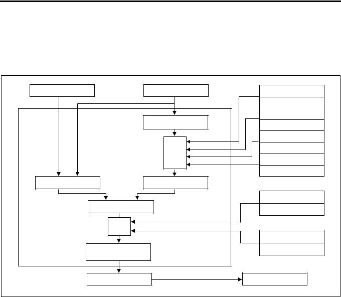
Electronic Control System
The electronic control system processes the data, which has been collected with various types of sensors, by means of the control program installed to ECM (engine control module) to totally control engine parameters such as fuel injection amount, injection timing, engine startup, altitude compensation, and EGR.
|
Sensor |
ECM |
Actuator |
Control |
|
Engine Rotating Speed |
Engine Driver Unit |
Fuel Injection Volume |
|
|
(Built-in Injection Pump) |
Control |
||
|
Fuel Injection Timing |
|||
|
Crankshaft Position |
Injection Pump |
Control |
|
|
Idle Rotating Speed |
|||
|
Spill Control Valve |
Control |
||
|
Accelerator Position |
|||
|
Timing Control Valve |
Starting Control |
||
|
Coolant Temperature |
|||
|
Altitude Control |
|||
|
Fuel Temperature |
EGR Valve |
EGR Control |
|
|
(Built-in Injection Pump) |
|||
|
Engine |
|||
|
Control |
|||
|
Module |
Intake Air Throttle |
||
|
Intake Air Pressure |
Intake Throttle Valve |
||
|
Control |
|||
|
Exhaust Magnetic Valve |
Exhaust Brake Control |
||
|
Vehicle Speed |
|||
|
Glow Plug |
Warm-Up System |
||
|
Control |
|||
|
Idle Up Volume |
|||
|
Glow Lamp |
Starting Aid Control |
||
|
Intake Air Temperature |
Self Diagnosis |
||
|
CHECK ENGINE Lamp |
|||
|
Atmospheric Pressure |
Swirl Change-Over Valve |
Intake Air Swirl Control |
|
|
(Built-in ECU) |
|||
|
LNW21ALF000301-X |
|||
ECM
ECM Description
The ECM is mounted in the glove box. The ECM monitors various data sent from diversified sensors and controls systems in the powertrain. The ECM diagnoses these systems to detect faults with respect to system operations and inform the driver of faulty condition via the CHECK ENGINE Lamp (MIL) and stores DTCs (diagnostic trouble codes). DTC identifies the trouble generation area to aid repairs by service operators.
Function of ECM
ECM supplies 5 V and 12 V voltages to various sensors and switches. Since powers are supplied via high resistances in ECM, Test Light, even when connected to the circuit, will not be lit. In a special case, a normal voltmeter does not indicate correct values since the resistance of the instrument is too low. To get accurate readings, you need a digital voltmeter whose input impedance is at least 10 MΩ . The special tool 5-8840- 0366-0 is a proper choice for this measurement. In the ECM, the output circuit is controlled by regulating the
Engine Control System 1A-5
grounding system or power circuit via transistor or either of the devices listed below.
•Output driver module (ODM)
•Quad drive module (QDM)
ECM and Components
The ECM is designed to offer excellent drivability and fuel economy while achieving exhaust gas emission control requirements. The ECM monitors engine and vehicle functions via various electronic sensors such as CKP (crank position) and VS (vehicle speed) sensors.
Voltages from ECM
The ECM supplies reference voltages to various switches and sensors. Resistances of the ECM are very high and this allows the ECM to supply voltages to these devices, and voltages actually applied to circuits are low and even connecting Test Light to individual circuits may fail turn-on. Since the voltmeter normally used in service factories has low input impedance, correct readings may not be obtained. To get accurate readings, a digital voltmeter whose input impedance is 10 MΩ (for example, 5-8840-0366-0) should be used.
Input/output devices of the ECM include analog-to- digital converter, signal buffer, counter, and special driver. By using electronic switches, the ECM controls most system components and turning off a switch closes the ground circuit. These switches are divided into four-switch or seven-switch groups, and the former group is called quad driver module (QDM) and controls up to four output pins respectively while the latter group is called output driver module (ODM) and controls up to seven outputs respectively. Note that all the outputs are necessarily not used in the control.
Electrically Erasable Programmable ROM (EEPROM)
EEPROM is a permanent memory chip and soldered to the board in the ECM. EEPROM stores program and calibration data, both of which are necessary for the ECM to control the powertrain. Different from conventional ROMs, EEPROM cannot be replaced with new component. If EEPROM fails, the complete ECM assembly must be replaced with new one.
Precautions on ECM Service
The ECM is designed to withstand ordinary currents used in operations of a vehicle. Be careful that the circuits must not be overloaded. To test the ECM to check open wiring or short, ECM circuits must be connected to the ground or voltages must not be applied to the ECM. To test ECM circuits, the digital voltmeter 5-8840-0366-0 should always be used.
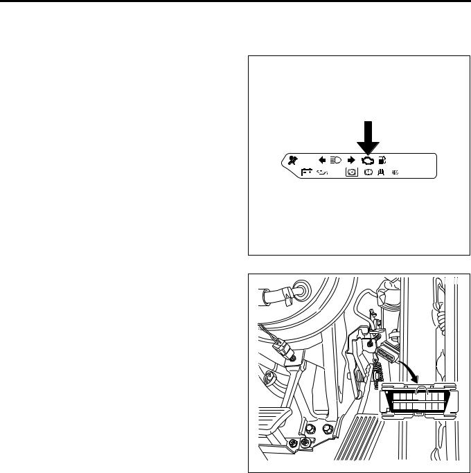
CHECK ENGINE Lamp (MIL)
Used as a means of communication between ECM and user usually in the user mode, by light on and off. If this lamp illuminates during operation, it warns some
engine fault to the user.
In a service factory, 4 pins and 6 pins of DLC (data link connector) can be short to check the DTC while the CHECK ENGINE Lamp (MIL) is flashing.
|
LNW21ASH000201 |
|||||||
|
1 |
2 |
3 |
4 |
5 |
6 |
7 |
8 |
|
9 |
10 11 12 13 14 15 16 |
||||||
|
LNW21ASH000301 |
1A-6 Engine Control System
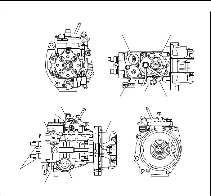
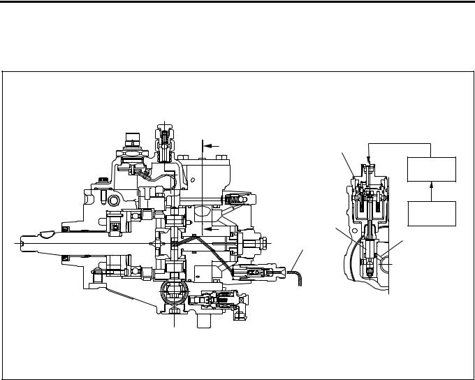
Electronically Controlled Distributor Injection Pump
|
1 |
2 |
|
|
4 |
||
|
5 |
3 |
|
|
12 |
||
|
11 |
||
|
10 |
6 |
|
|
9 |
||
|
7 |
||
|
8 |
||
|
LNW21ALF000101 |
|
Legend |
|||
|
1. |
Spill control valve |
7. |
Timer |
|
2. |
Pump cam position sensor (engine speed |
8. |
Timing control valve |
|
sensor) |
9. |
Delivery valve holder |
|
|
3. |
Inlet pipe |
10. |
Compensation ROM |
|
4. |
Fuel temperature sensor |
11. |
Overflow pipe |
|
5. |
Accumulator |
12. |
Overflow valve |
|
6. |
Bearing cover |
||
An electronically controlled distributor injection pump is employed to meet the requirements of the long-term exhaust gas control without impairing the fuel efficiency and output. These features allow finer particles of injected fuel, and optimum injection timing and injection amount while the vehicle is traveling, which was impossible with the former injection pump.
Fuel Dehumidifying Agent
Sliding parts in the injection pump are lubricated by the fuel (light oil) as in the existing distributor type injection pump. If dehumidifying agent is mixed in the fuel, it may exert adverse influence on the sliding parts. Particularly, dehumidifying agent of alcohol type is characterized by introducing moisture into water, causing rust generation. It should be explained to customers not to use fuel dehumidifying agent or other fuel additives.
Engine Control System 1A-7
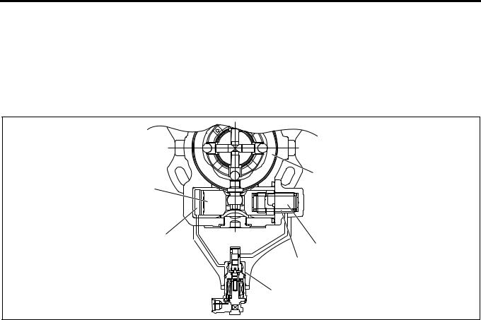
Structure and Operation
1.Higher pressure of injection fuel
An inner cam with a cam ring and radial plunger are used to increase the pressure of the injection fuel.
The cam ring is supported on the pump body side and provided with projections (cams) on the internal periphery.
Four plungers are provided at an interval of 90°, incorporated in the rotor integrated with the drive shaft, and in contact with the internal periphery of the cam ring in the radial direction through the roller.
When the drive shaft rotates, the plunger moves on the cam ring internal surface through the rolling of the roller, pushed out in the shaft center direction with the inner cam and compresses the fuel.
Four plungers operate simultaneously. This enables higher pressure (75 ~ 130 MPa) and high rigidity is obtained since the load becomes relative load in the radial direction.
Plunger diameter is ø7.5mm and the cam lift is 2.5mm.
1
5


 2 4
2 4 


3
LNW21ASH000401
Legend
1.Cam ring
2.Rotor
3.Timer piston
4.Roller
5.Plunger
2.Injection timing control
Injection timing is adjusted by shifting the cam ring phase with the fuel pressure applied to the back of the timer piston. The fuel pressure applied to the timer piston is controlled with the ECM (engine control module) through the timing control valve.
3.Fuel injection amount control
Fuel injection amount is adjusted by opening or closing the fuel high pressure circuit with the high response SPV (spill control valve).
EDU (engine driver unit; a high voltage driver) is employed to drive the SPV at a high speed. EDU can drive the SPV of high fuel pressure at a high speed by the high voltage and high speed energizing system.
4.Pump ROM
In order to compensate the variation of correlation between the fuel pump and engine, variation of the injection amount inherent to the injection pump is corrected.
5.Air bleeding of injection pump
a.Pumping until the pump is hard to operate.
b.Start the engine. If not started, repeat pumping.
c.After the engine is started, keep the engine speed at 1000 to 1500rpm for about 10 seconds.
d.Stop the engine.
e.Check for fuel leakage.
1
4
3
2
LNW21ASH000501
Legend
1.Priming pump
2.Plug
3.Sensor
4.Cartridge
1A-8 Engine Control System
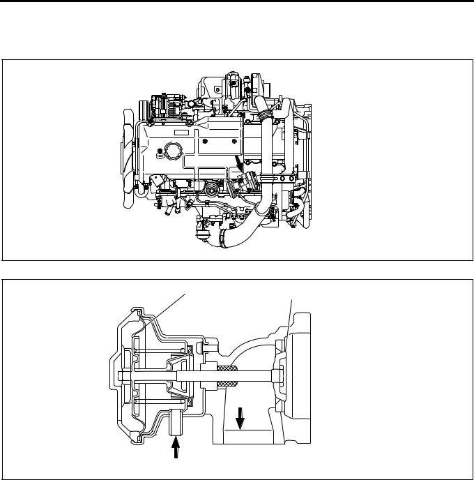
EGR (Exhaust Gas Recirculation) Valve
In order to decrease NOx (nitrogen oxide) in the exhaust gas, an EGR system is employed.
The EGR valve is vacuum control type.
LNW21ASF000101
1
2
 3
3
3
4
LNW21ASF000201
|
Legend |
|||
|
1. |
Diaphragm |
3. |
Exhaust gas |
|
2. |
Valve |
4. |
Vacuum |
![]()
Engine Control System 1A-9
Injection Nozzle
Legend
1. Edge filter
A two-step valve opening pressure nozzle is used as the injection nozzle. Spray particle size is reduced by reducing the injection hole diameter.
To prevent clogging of the nozzle injection hole, an edge filter is provided at the nozzle holder inlet.
Reference:
If the injection nozzle hole is clogged, ECM corrects the cylinder inside condition.
The cylinder correction amount in the Tech 2 data list is helpful to know the injection nozzle condition.
|
Item |
Engine 4HK1 |
||
|
Valve |
1st valve opening |
18.0 {185} |
|
|
opening |
pressure |
(Nominal value) |
|
|
pressure |
|||
|
2nd valve |
22.0 {225} |
||
|
MPa(kg/cm2) |
|||
|
opening pressure |
(Nominal value) |
||
|
No. of injection holes — Injection |
5 -ø0.25 |
||
|
hole diameter (mm) |
|||
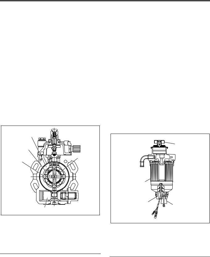
Fuel Filter with Sedimentor
In order to secure the lubrication efficiency in the injection pump, a fuel filter with sedimentor to remove moisture in the fuel is provided.
This filter is provided with a priming pump to bleed the air from the injection pump.
1
2
LNW21ASH000601
Legend
1.Priming pump
2.Fuel filter & sedimentor
1A-10 Engine Control System
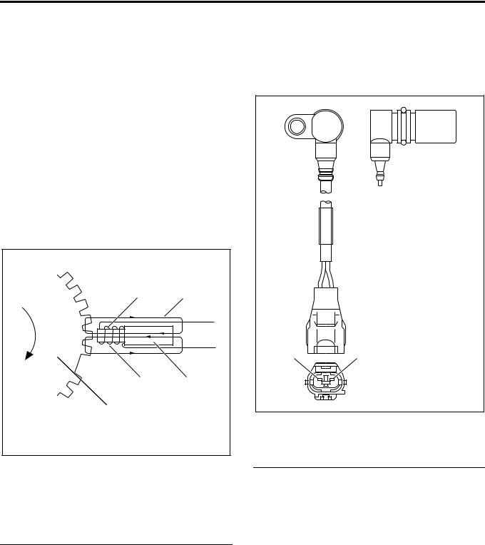
Pump CMP (Cam Position) Sensor (Engine Rotation Sensor ) = NE Sensor
The pump CMP sensor is positioned on the outer surface of the cam ring of the pump chamber. The pulser installed to the injection pump drive shaft interrupts the magnetic flux generated by the permanent magnet and iron core of the sensor according to the shaft rotation to generate AC wave signal to the coil. This is transmitted to ECM (engine control module) and converted to square wave signal. engine speed and cam position are calculated by this signal.
• Calculation of engine speed: No. of pulses per hour is counted.
• Calculation of cam position: When the cam ring slides, timing of signal read from the pulse of the sensor installed to the cam ring varies. ECM calculates the time difference between this signal and signal of the crank position sensor and calculates the cam position.
1 2
4 3
5
LNW21ASH000701
Legend
1.Iron core
2.Magnetic flux
3.Permanent magnet
4.Coil
5.Pulser
CKP (Crank Position) Sensor
CKP sensor to detect the crank position is installed to the flywheel housing. The sensor detects the rotating angle of the crankshaft in non-contact condition with the pointer installed to the flywheel and sends pulse signal to ECM. ECM calculates the injection timing at the pump cam position based on this pulse signal.
12
LNW21AMH000101
Legend
1.(–) Pin
2.(+) Pin
Engine Control System 1A-11
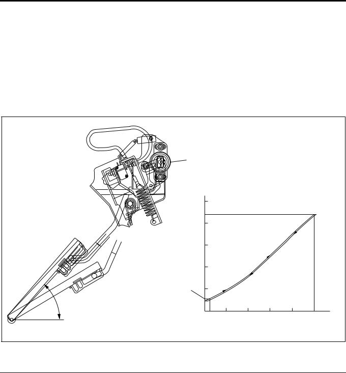
Accelerator Position Sensor
The accelerator control is accelerator position sensor type. This sensor is a potentiometer (variable resistance) installed to the accelerator pedal. Reference voltage is constantly applied to the sensor from ECM (engine control module) and the accelerator pedal stepping angle is detected from varying voltage. An accelerator switch (idle position switch) is also installed to the accelerator pedal. The accelerator switch is turned ON when the accelerator pedal is released and OFF when the accelerator pedal is stepped on.
|
1 |
||||||
|
(V) |
||||||
|
5 |
||||||
|
(WOT) |
||||||
|
4 |
||||||
|
Voltage |
3 |
|||||
|
Output |
2 |
|||||
|
2 |
1 |
|||||
|
49 |
(Idle) |
|||||
|
0 |
10 |
20 |
30 |
40 |
50 (mm) |
|
|
Stroke (on Pedal) |
||||||
|
LNW21AMF000701-X |
|
Legend |
|
|
1. Accelerator position sensor |
2. Accelerator switch operating point |
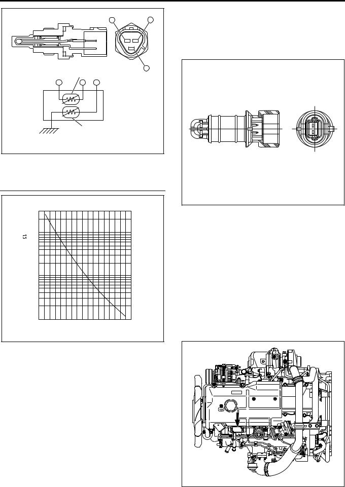
Engine Coolant Temperature Sensor (Coolant Temperature Sensor / ECT)
The engine coolant temperature sensor serves for both the ECM and thermo meter unit. The engine coolant temperature sensor is of the thermistor type that the electric resistance reduces with the increase of the temperature. It is installed on the left front of the cylinder head.
1A-12 Engine Control System
|
A |
C |
||
|
B |
|||
|
1 |
|||
|
A |
C |
B |
|
|
2 |
|||
|
LNW21ASH000801 |
Legend
1.Thermistor for ECM
2.Thermistor for thermo meter
[Thermistor Characteristics]
|
30 |
||
|
20 |
||
|
) |
10 |
|
|
(k |
7.0 |
|
|
5.0 |
||
|
Value |
||
|
3.0 |
||
|
Resistance |
||
|
2.0 |
||
1.0
0.7
0.5
0.3
0.2
0.1
-20 0 20 40 60 80 100 120
Engine Coolant Temperature ( C)
LNW21ASH000901-X
Fuel Temperature Sensor
Fuel temperature sensor is installed in the pump chamber full of fuel. Thermistor is used for the temperature detector as in the thermo sensor and convert the changes of temperature to changes of resistance and values transmits to ECM.
Vehicle Speed Sensor
The vehicle speed sensor is used commonly with the speedometer. ECM receives signal from the speedometer.
By one turn of the speedometer driven gear, 25 pulses are generated indicating 60 km/h at 637rpm.
Intake Air Temperature Sensor
Intake air temperature sensor is installed to the intake duct. Thermistor is used for the temperature detector as in the thermo sensor to convert the changes of temperature to changes of resistance values and transmits to ECM.
Atmospheric Pressure Sensor
The atmospheric pressure sensor is incorporated in ECM.
MAP (Intake Air Pressure) Sensor
The MAP sensor is installed to the cylinder head cover. The MAP sensor is composed of piezo type semiconductor pressure element. Reference voltage is constantly applied to the MAP sensor from ECM and manifold pressure is detected by the changes of voltage. When the manifold pressure is low (at idling), low voltage signal is sent to ECM and when the pressure is high (at full throttle), high voltage signal is transmitted to ECM.
Engine Control System 1A-13
MAP (Intake Air Pressure) Sensor
|
Output Voltage (V) |
[MAP Sensor Characteristics] |
|||
|
6 |
Absolute |
|||
|
Pressure |
||||
|
1 |
2 |
|
5 |
4 |
3 |
|||||
|
LNW21AMF000801-X |
|||||||
|
Legend |
|||||||
|
1. |
Pressure at idling (low pressure) |
4. |
Output pin |
||||
|
2. |
Pressure at rating point (absolute pressure (high |
5. |
Ground pin |
||||
|
pressure)) |
6. |
Vacuum hose connected pipe |
|||||
|
3. |
Power pin |
||||||
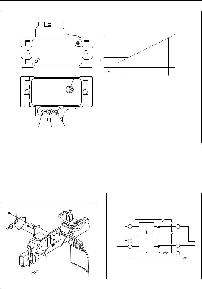
EDU (Engine Driver Unit)
EDU enables SPV high speed drive at high fuel pressure by the high voltage and high speed energizing system.
Maximum charging voltage is about 150V.
Legend
1.EDU
2.Left side cover
|
Connecting Diagram |
|||
|
Battery |
High Voltage |
D SPV+ |
|
|
A |
Generating |
||
|
Circuit |
|||
|
ECM |
Control |
||
|
B |
|||
|
ECM |
Circuit |
E |
|
|
C |
SPV |
||
|
F |
Ground |
||
|
LNW21ASH001601-X |
1A-14 Engine Control System
SPV (Spill Control Valve)
Fuel injection amount is controlled with the highresponse SPV by opening and closing the fuel high pressure circuit.
SPV is incorporated in the injection pump.
|
B |
1 |
|
|
7 |
||
|
2 |
||
|
3 |
||
|
B |
5 |
|
|
4 |
||
|
6 |
||
|
8 |
||
|
LNW21AMF000901 |
|
Legend |
|||
|
1. |
SPV drive signal |
5. |
Valve |
|
2. |
EDU |
6. |
High pressure fuel passage |
|
3. |
ECM |
7. |
SPV |
|
4. |
High pressure fuel |
8. |
B-B section |
Engine Control System 1A-15
TCV (Timing Control Valve)
TCV using a solenoid valve is installed to the oil pressure timer. Duty (energizing rate) controlled current with ECM increases or decreases the valve opening time to control the oil pressure in the high pressure chamber side. The timer piston is moved by the balance with the timer spring. By sliding the cam ring connected movably with the timer piston in the rotating direction, the injection timing is controlled.
1
6
5
2
3
4
7 
LNW21ASF000401
|
Legend |
|||
|
1. |
Cam ring |
5. |
High pressure chamber |
|
2. |
Low pressure chamber |
6. |
Timer piston |
|
3. |
Timer spring |
7. |
From ECM |
|
4. |
TCV |
||
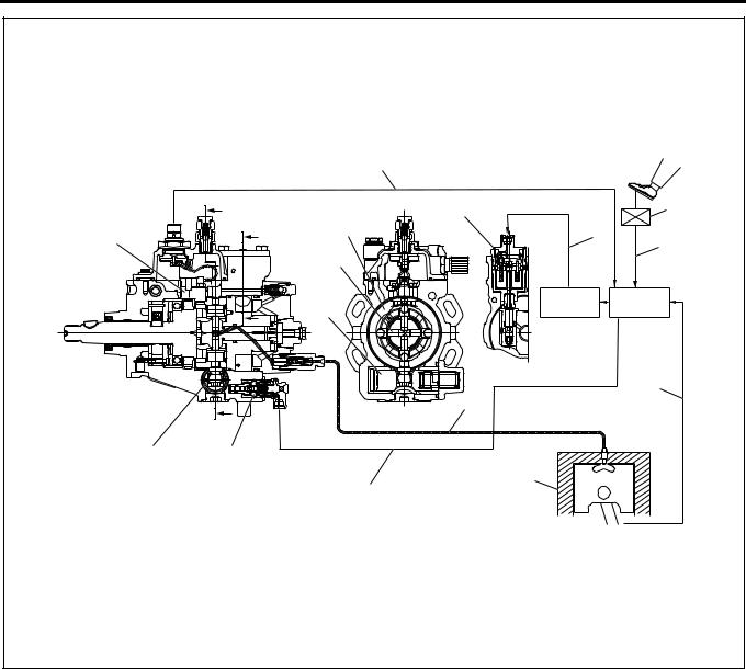
Electronic Control Distributor Pump System System Overview
The accelerator control uses an accelerator position sensor. The accelerator sensor of the potentio meter (variable resistance) type is installed to the accelerator pedal. Reference voltage is constantly applied to the sensor from the ECM (engine control module) to detect the accelerator pedal stepping angle from changes of voltage. An idle position switch (accelerator switch ) is also installed to the accelerator pedal. The idle position switch (accelerator switch ) is turned ON when the accelerator pedal is released and OFF when the accelerator is stepped on.
ECM detects the accelerator pedal stepping angle as AP (accelerator position) signal and after calculating, transmits SPV (spill controller valve) drive signal to EDU (engine driver unit).
EDU enables high speed drive of SPV which controls fuel injection amount.
The fuel injection amount is controlled by opening and closing the fuel high pressure circuit with the high response SPV.
SPV is incorporated in the injection pump.
The spill control valve and timing control valve are
electronically controlled with ECM (engine control module).
1A-16 Engine Control System
|
4 |
||||
|
A |
5 |
10 |
||
|
B |
3 |
6 |
||
|
17 |
||||
|
9 |
||||
|
2 |
||||
|
7 |
8 |
|||
|
B |
1 |
|||
|
19 |
||||
|
11 |
||||
|
A |
13 |
|||
|
18 |
||||
|
16 |
15 |
|||
|
12 |
||||
|
14 |
||||
|
LNW21ALF003101 |
|
Legend |
|||
|
1. |
Timer piston |
11. |
Crankshaft position signal |
|
2. |
Plunger |
12. |
Engine |
|
3. |
Cam ring |
13. |
High pressure fuel passage |
|
4. |
Pump cam position signal (engine speed signal) |
14. |
Injection timing control signal |
|
5. |
Spill control valve |
15. |
Timing control valve |
|
6. |
Spill control valve drive signal |
16. |
Timer piston |
|
7. |
Engine driver unit |
17. |
Pump cam position sensor (engine speed |
|
8. |
Engine control module |
sensor) |
|
|
9. |
Accelerator pedal opening signal |
18. |
A-A section |
|
10. |
Accelerator position signal |
19. |
B-B section |
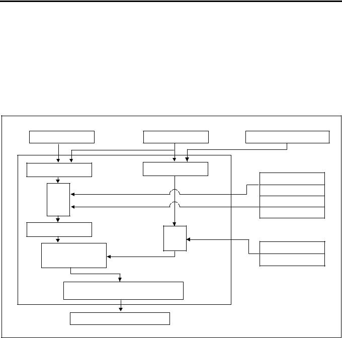
Fuel Injection Amount Control
The electromagnetic spill valve is opened by the signal from ECM (engine control module), pressure in the fuel forced feed unit (rotor unit) is decreased and injection is completed. Injection amount is controlled at this timing.
Engine Control System 1A-17
Operation
ECM calculates the basic injection amount optimum to the engine operating conditions and the maximum injection amount at that engine condition, compares and selects lower injection amount. By adding the phase compensated with the compensation ROM to that injection amount, the final injection amount is determined.
At the time of start, the optimum fuel injection amount is determined by the starter signal and coolant temperature. (Injection amount increases more when the coolant temperature is lower.)
|
Accelerator Position |
Engine Speed Sensor |
Intake Air Pressure |
|
Sensor |
Sensor |
|
|
Increase When Higher |
||
|
Intake Air Temperature |
||
|
Basic Max. Injection |
Sensor |
|
|
Varying Depending on |
||
|
Amount |
||
|
Conditions |
||
|
Fuel Temperature Sensor |
||
|
Compen- |
Increases When Lower |
|
|
sation |
Coolant Temperature |
|
|
Sensor |
||
|
Increases When Lower |
||
|
Basic Injection Amount |
Max. Injection Amount |
|
|
Fuel Temperature Sensor |
||
|
Select Lower Injection |
Compensates to Increasing |
|
|
Amount Side |
||
|
Side When Higher |
||
|
Compen- |
||
|
sation |
||
|
Compensation ROM |
||
|
Injection Amount |
Compensation Value |
|
|
of Each Pump |
||
|
Determine |
||
|
EDU |
Electromagnetic Spill Valve |
|
|
LNW21AMF001001-X |
1.Basic injection amount
Determined by accelerator opening and engine speed.
2.Max. injection amount
Maximum injection amount is determined by adding compensation by signals of sensors to the basic maximum injection amount (amount which can be theoretically injected) determined based on the engine speed.
a.Intake air pressure compensation
When the intake air pressure is high, the air amount is increased and the injection amount is increased.
b.Intake air temperature compensation
Injection amount is increased or decreased depending on the difference of density based on the intake air temperature.
c.Fuel temperature compensation
When the fuel temperature decreases, the injection amount is increased.
d.Coolant temperature compensation
When the coolant temperature is lower, the injection amount is increased to secure the operability immediately after the cold start.
3.Injection amount compensation
Since the actual injection amount decreases in comparison with the designated value of injection amount when the fuel temperature is higher, designated injection amount value is increased.
Fuel Injection Timing Control
•Timing control valve is duty-controlled according to a signal from ECM (engine control module) to control the fuel injection start timing.
•Using the crankshaft angle feed back system, highly precise control is effected.
1A-18 Engine Control System
Operation
ECM calculates the optimum target injection timing for the engine condition, adding the compensation by signals from sensors based on the basic target injection timing.
At the time of start, the injection timing is determined by the starter signal, coolant temperature and engine speed (at the higher engine speed, the injection timing angle advances.)
Crank angle feedback system is employed to calculate the actual injection timing and feed back the result at the target injection timing.
|
Accelerator Position |
Speed Sensor |
Crank Position Sensor |
|
|
Sensor |
|||
|
Basic Target Injection |
Actual Injection Timing |
||
|
Timing |
Intake Air Pressure |
||
|
Sensor |
|||
|
Angle Advances |
|||
|
Compen- |
When Lower |
||
|
Coolant Temperature |
|||
|
sation |
|||
|
Sensor |
|||
|
Angle Advances |
|||
|
When Lower |
|||
|
Target Injection Timing |
Compen- |
||
|
sation |
|||
|
Comparison with Target |
Compensation ROM |
||
|
Injection Timing and |
Compensation Value |
||
|
Actual Injection Timing |
of Each Pump |
||
|
Calculation of Duty Ratio |
|||
|
Timing Control Valve |
|||
|
LNW21AMF001101-X |
1.Basic target injection timing
Determined based on the accelerator opening and engine speed.
2.Injection timing compensation
a.Intake air pressure compensation
Basic target injection timing is compensated by the intake air pressure. When the atmospheric pressure is low on a altitude, for instance, the injection timing angle is advanced.
b.Coolant temperature compensation
Basic target injection timing is compensated based on the coolant temperature. When the coolant temperature is low, the injection timing angle is advanced.
3.Feedback control
a.Calculation of actual injection timing
When relation between the compression TDC position and crank angle reference position signal is correct on the engine side and the relation between the injection waveform and
cam angle signal is correct on the pump side, actual injection timing θ n can be calculated by calculating the phase difference θ i between the crank angle reference position signal and cam angle signal.
![]()
Engine Control System 1A-19
6
θ 
1
5
 θ
θ 
4
2
3
LNW21ASH001701
Legend
1.Engine
2.Pump
3.Injection waveform
4.Cam angle signal
5.Crank angle reference position signal
6.Actual compression TDC
b.Feedback control
Timing control valve duty ratio is calculated so that the actual injection timing coincides the target injection timing.
Idle Speed Control
•Idle speed is controlled by increasing or decreasing the specified fuel injection amount value based on the signal from ECM (engine control module).
Operation
1.Feedback control
When there is a difference between the target speed calculated by the ECM and engine speed at the idle speed, the fuel injection amount is controlled by changing the signal to the electromagnetic spill valve and controls so that the engine speed coincides the idle speed.
2.Warm-up control
Optimum fast idle engine speed is controlled at idling by the coolant temperature.
3.Estimated control
Immediately after changing over the air conditioning switch, before the engine speed changes, the injection amount is changed by a constant amount to prevent change of idle speed by the change of load given to the engine.
Idle Speed (P.N Range in A/T Vehicle) [r/min]
|
M/T |
A/T |
||
|
Engine speed at |
Approx. 580 |
Approx. 650 |
|
|
no load |
|||
|
Air conditioner |
Approx. 800 |
Approx. 870 |
|
|
system ON |
|||
1A-20 Engine Control System
Component Layout
Fuse Layout
[Fuse Box Label, In Glove Box]
|
22 |
19 |
16 |
13 |
10 |
7 |
4 |
1 |
|
|
25 |
23 |
20 |
17 |
14 |
11 |
8 |
5 |
2 |
|
26 |
24 |
21 |
18 |
15 |
12 |
9 |
6 |
3 |
1
[Fuse Box, Front Left of Radiator]
27 28
LNW21ALF000401-X
Legend
1. Spare fuse
|
No. |
Indication on label |
Capacity |
Devices connected |
|
|
1 |
CONTROLLER |
10A |
Control unit |
|
|
2 |
HAZARD,HORN (12V) |
15A |
Hazard warning flashing lamp, horn |
|
|
HAZARD,HORN (24V) |
10A |
|||
|
3 |
— |
10A |
— |
|
|
4 |
AIR CON (12V) |
10A |
Air conditioner |
|
|
HEATER,AIR CON (24V) |
15A |
Heater, air conditioner |
||
|
5 |
FUEL, SEAT HEATER (24V) |
10A |
Fuel, seat heater |
|
|
6 |
ABS, HAB, RETARDER (24V) |
15A |
ABS, HAB, retarder |
|
|
Engine Control System 1A-21 |
||||
|
No. |
Indication on label |
Capacity |
Devices connected |
|
|
7 |
ROOM LAMP |
15A |
Room lamp |
|
|
8 |
STOP LAMP |
10A |
Stop lamp |
|
|
9 |
POWER WINDOW (24V) |
20A |
Power window |
|
|
10 |
TAIL.ILLUMI (12V) |
15A |
Tail lamp |
|
|
TAIL.ILUMI (24V) |
10A |
|||
|
11 |
FOG.CORNER |
10A |
Fog lamp, cornering lamp |
|
|
12 |
ELEC.PTO (24V) |
10A |
PTO switch (electric PTO) |
|
|
13 |
WIPER,WASHER |
15A |
Wiper, window washer |
|
|
14 |
TURN |
10A |
Turn signal lamp |
|
|
15 |
GENERATOR (12V) |
15A |
Generator |
|
|
ELEC.PTO (24V) |
20A |
PTO solenoid valve (electric PTO) |
||
|
16 |
MIRROR HEAT (12V) |
10A |
Heated side mirror |
|
|
ENG.CONT (24V) |
15A |
ECM |
||
|
17 |
MIRROR |
10A |
Electrically operated mirror |
|
|
18 |
CIGAR,AUDIO |
10A |
Cigarette lighter, audio |
|
|
19 |
METER (12V) |
10A |
Meter |
|
|
METER (24V) |
15A |
|||
|
20 |
ENGINE STOP (12V) |
10A |
Engine stop |
|
|
HSA (24V) |
10A |
HSA |
||
|
21 |
AIR BAG |
10A |
SRS airbag |
|
|
22 |
STARTER |
10A |
Starter |
|
|
23 |
H/LAMP RH |
10A |
Headlamp, RH |
|
|
24 |
H/LAMP LH |
10A |
Headlamp, LH |
|
|
25 |
HEATER (12V) |
30A |
Heater |
|
|
ENG CONTROLLER (24V) |
30A |
ECM (except for turbocharged vehicles) |
||
|
26 |
POWER WINDOW (12V) |
30A |
Power window |
|
|
External Fuse Box |
||||
|
No. |
Indication on label |
Capacity |
Devices connected |
|
|
27 |
MARKER LAMP |
10A |
Marker lamp |
|
|
28 |
COND FAN |
10A |
Condenser fan |
|
1A-22 Engine Control System
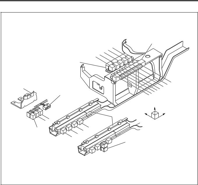
Relay Layout
|
Relay Box No.1 |
|||||
|
13 |
|||||
|
16 15 14 |
|||||
|
18 |
|||||
|
Relay Box No.2 |
|||||
|
12 |
|||||
|
Bracket |
11 |
||||
|
Spare Power Circuit |
6 |
7 |
8 9 10 |
||
|
5 |
|||||
|
Upper |
|||||
|
Fuse & |
Front |
Right |
|||
|
Relay Box |
|||||
|
19 20 |
|||||
|
Cooler Relay |
4 |
||||
|
3 |
|||||
|
2 |
|||||
|
1 |
17 |
||||
|
LNW21ALF006101-X |
|
No. |
Legend |
||
|
1 |
12 |
V: On relay |
|
|
24 |
V: Charge relay |
||
|
2 |
Horn relay |
||
|
3 |
12 |
V: ABS, VSV, FICD, EXH brake |
|
|
24 |
V: Headlamp relay |
||
|
4 |
Tail relay |
||
|
5 |
12 |
V: Headlamp relay |
|
|
24 |
V: 4WD relay |
||
|
6 |
Dimmer relay |
||
|
7 |
Power window relay |
||
|
8 |
Fog lamp relay |
||

Engine Control System 1A-23
|
No. |
Legend |
||
|
9 |
Cornering lamp relay |
||
|
10 |
Air conditioner thermo relay |
||
|
11 |
12 |
V: Charge relay |
|
|
24 |
V: Key on relay |
||
|
12 |
Heater & air conditioner relay |
||
|
24 |
V: PTO cut relay for electric PTO in fire engine (MT) |
||
|
24 |
V: PTO solenoid relay for electric PTO (AT) |
||
|
13 |
|||
|
12 |
V: Exhaust brake cut relay (MT) |
||
|
24 |
V: Idle on relay for fire engine (AT) |
||
|
24 |
V: Idle stop, wiper relay (with CFS (clutch free system)) |
||
|
24 |
V: PTO solenoid relay for electric PTO (MT) |
||
|
24 |
V: PTO buzzer relay for electric PTO (AT) |
||
|
14 |
|||
|
12 |
V: OD off relay (AT) |
||
|
24 |
V: Idle keep relay for fire engine (AT) |
||
|
24 |
V: Idle stop, radio relay (with CFS) |
||
|
24 |
V: PTO main relay for electric PTO (MT) |
||
|
15 |
24 |
V: Garbage relay for garbage collector (AT) |
|
|
24 |
V: Indicator lamp relay for fire engine (AT) |
||
|
24 |
V: Idle stop, engine control module relay (with CFS) |
||
|
16 |
4WD relay |
||
|
24 |
V: Idle stop, mirror relay (with CFS) |
||
|
24 |
V: Full automatic air conditioner, high relay |
||
|
17 |
|||
|
24 |
V: Automatic air conditioner, high relay |
||
|
24 |
V: Shift lock relay for fire engine (AT) |
||
|
18 |
24 |
V: Shift relay for fire engine (AT) |
|
|
24 |
V: PTO main relay for electric PTO (MT) |
||
|
19 |
24 |
V: PTO solenoid relay for electric PTO (MT) |
|
|
20 |
24 |
V: PTO cut relay for electric PTO (MT) |
|

1A-24 Engine Control System
Engine Component Layout
1
4
5
11
6
9
10
LNW21ALF003001
|
Legend |
|||
|
1. |
EGR valve |
7. |
Fuel temperature sensor (FT sensor) |
|
2. |
Crank position sensor (CKP sensor) |
8. |
Oil pressure SW |
|
3. |
Intake throttle body |
9. |
TCV |
|
4. |
MAP sensor |
10. |
ROM |
|
5. |
NE sensor |
11. |
Coolant temperature sensor |
|
6. |
SPV |
||
Engine Control System 1A-25
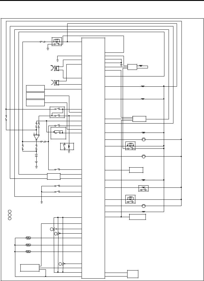
Circuit diagram
ECM wiring diagram (1)
|
D24 |
|||||||
|
Main Relay |
|||||||
|
D13 |
D9 |
||||||
|
D16 |
|||||||
|
B6 |
D26 |
||||||
|
Pump Cam Position Sensor |
B5 |
A11 |
Spill Valve |
||||
|
D20 |
|||||||
|
EDU |
|||||||
|
A15 |
|||||||
|
Crankshaft Position Sensor |
B12 |
D6 |
|||||
|
B11 |
D12 |
Timing Control Valve |
|||||
|
Vehicle Speed |
D7 |
||||||
|
Sensor |
|||||||
|
Cooler |
EGR EVRV |
||||||
|
Compressor |
A1 |
||||||
|
Freezer |
|||||||
|
Compressor |
Neutral SW |
A17 |
|||||
|
A20 |
|||||||
|
A2 |
B3 |
||||||
|
Inhibitor SW |
A3 |
TCM |
|||||
|
B9 |
|||||||
|
Exhaust Brake SW |
A21 |
||||||
|
(A/T) |
A19 |
Swirl Control |
|||||
|
A6 |
A22 |
VSV |
|||||
|
Key SW |
Clutch SW |
D21 |
Check Engine Lamp |
||||
|
(M/T) |
|||||||
|
D10 |
|||||||
|
Starter Relay |
D22 |
Spill Valve Relay |
|||||
|
Glow Lamp |
|||||||
|
Warm-Up SW |
B2 |
A13 |
|||||
|
TECH 2 |
|||||||
|
A16 |
|||||||
|
ABS/ASR |
|||||||
|
B8 |
ECM |
Exhaust Brake VSV1 |
|||||
|
ECU |
D4 |
||||||
|
Diagnostic SW |
A9 |
D23 |
Glow Relay |
||||
|
Idle SW |
|||||||
|
A10 |
|||||||
|
Stop Lamp Relay |
|||||||
|
A5 |
|||||||
|
B7 |
|||||||
|
D19 |
Exhaust Brake Lamp |
||||||
|
1 |
Accelerator Position Sensor |
A12 |
Intake VSV |
||||
|
2 |
Idle Up Volume |
C3 |
B10 |
Tachometer |
|||
|
5 |
PTO Position Sensor |
||||||
|
C4 |
|||||||
|
C11 |
ECM |
: Engine Control Module |
|||||
|
1 |
|||||||
|
C10 |
EDU |
: Engine Driver Unit |
|||||
|
Coolant Temperature |
2 |
||||||
|
Sensor |
C1 |
||||||
|
EVRV: Electric Vacuum Regulating Valve |
|||||||
|
Fuel Temperature |
|||||||
|
Sensor |
C12 |
TCM |
: Transmission Control Module |
||||
|
Intake Air Temperature |
VSV |
: Vacuum Switching Valve |
|||||
|
Sensor |
C15 |
||||||
|
5 |
C14 |
||||||
|
Intake Air |
C9 |
||||||
|
Pressure Sensor |
C6 |
D3 |
|||||
|
Pump |
|||||||
|
C5 |
D17 |
||||||
|
ROM |
LNW21AXF000301-X |
||||||
1A-26 Engine Control System
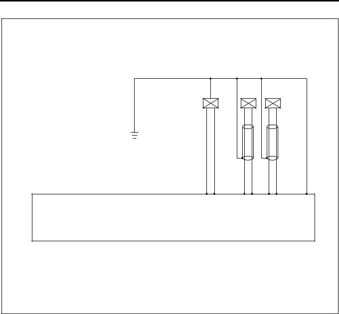
ECM Wiring Diagram (2)
|
1.25 B/L |
||||||
|
CKP |
NE |
|||||
|
ROM |
Sensor |
Sensor |
||||
|
0.5 |
0.5 |
0.5 |
0.5 0.5 |
0.5 |
||
|
G/B |
G/R |
W |
R |
G |
L |
|
|
D17D3 |
B5B11 |
B6B12 |
D13 |
|||
|
(+) () |
(+) () |
|||||
|
Engine Control Module (ECM) |
||||||
|
Compensation ROM and NE Sensor are built in the Injection Pump |
||||||
|
LNW21ALF000701-X |
Engine Control System 1A-27
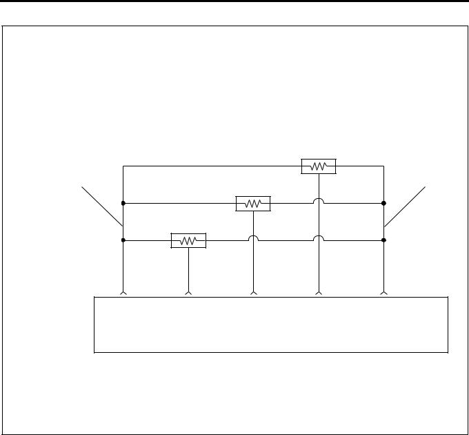
ECM Wiring Diagram (3)
|
AP (Accelerator Position) Sensor |
|||||
|
2 |
1 |
||||
|
Idle Up Volume |
|||||
|
PTO Accelerator Sensor |
|||||
|
0.5 |
0.5 |
0.5 |
0.5 |
0.5 |
|
|
Y/B |
R/B |
Y/G |
G/O |
Y/R |
|
|
Engine Control Module |
C6 |
C14 |
C10 |
C11 |
C3 |
|
(ECM) |
(Sensor |
Signal |
Signal |
Signal |
(Sensor |
|
Ground) |
Power) |
||||
|
LNW21ALF000501-X |
Characteristics of Circuit
•Multiple DTC is generated when several troubles (failures) occur. When multiple sensors or switches share a ground, or an open wiring or short occurs on the share power supply or ground, DTCs with respect to related sensors or switches are displayed.
If several DTCs are displayed, it is necessary to inspect the shared power supply or ground for open wiring or short.
The harness 1 shown above figure is the power common to the AP sensor and idle up volume, and the harness 2 is a common ground. In the event of open wiring in wire 1 or 2, DTC 24 and 31 are displayed at the same time. Like this, the case where two or more DTC’s are displayed is the multiple DTC.
•If multiple DTC24 and 31 are displayed, the power supply wire 1 or ground wire 2 must be checked.
|
DTC |
Sensor actuator (detection item) |
||
|
24 |
Accelerator position |
Connector not |
|
|
sensor |
connected, |
||
|
harness open wiring, |
|||
|
31 |
idle up volume |
||
|
or |
|||
|
short, failure of |
|||
|
main unit |
|||
1A-28 Engine Control System
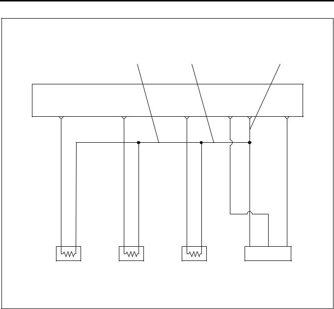
ECM wiring diagram (4)
|
3 |
2 |
1 |
|||||
|
ECM |
Sensor |
||||||
|
Ground |
|||||||
|
C-1 |
C-12 |
C-15 |
C-9 |
C-5 |
C-4 |
||
|
0.5 |
0.5 |
0.5 |
|||||
|
Y/G |
W/ |
L/W |
|||||
|
GRN |
|||||||
|
0.3 |
0.5 |
0.3 |
0.5 |
0.3 |
0.5 |
||
|
BLU/ |
W/ |
R/G |
W/ |
R/Y |
W/ |
||
|
RED GRN |
GRN |
GRN |
|||||
|
SIG |
GND |
SIG |
GND |
SIG |
GND |
||
|
Engine Coolant |
Fuel Temperature |
Intake Air |
Intake Air |
||||
|
Temperature |
Sensor |
Temperature |
Pressure Sensor |
||||
|
Sensor |
Sensor |
||||||
|
LNW21ALF000601-X |
Characteristics of Circuit
•Multiple DTC is generated when several troubles (failures) occur. When multiple sensors or switches share a ground, or an open wiring or short occurs on the share power supply or ground, DTCs with respect to related sensors or switches are displayed.
If several DTCs are displayed, it is necessary to inspect the shared power supply or ground for open wiring or short.
The harness 1 in above figure is a common ground for the engine coolant temperature sensor, fuel temperature sensor, intake air temperature sensor and intake air pressure sensor. In the event of the open wiring in the wire 1, DTC 21, 23, 41 and 32 are displayed at the same time. In the event of the open wiring in the wire 2, DTC 21, 23, and 41 are displayed at the time. Like this, the case where two or more DTC’s are displayed is the multiple DTC.
•If multiple DTC21, 23, 41, and 32 are displayed, the ground wire 1 must be checked.
•If multiple DTC21, 23, and 41 are displayed, the ground wire 2 must be checked.
•If multiple DTC21 and 23 are displayed, the ground wire 3 must be checked.
|
DTC |
Sensor actuator (detection item) |
||
|
21 |
Engine coolant |
||
|
temperature sensor |
Connector not |
||
|
connected, |
|||
|
23 |
Intake air temperature |
||
|
sensor |
open wiring or |
||
|
short of harness, |
|||
|
41 |
Fuel temperature sensor |
||
|
failure of |
|||
|
main unit |
|||
|
32 |
Intake air pressure |
||
|
sensor |
|||
![]()
Engine Control System 1A-29
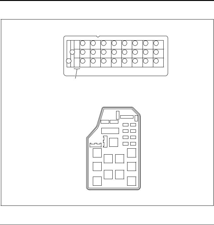
ECM Pinouts
ECM is installed in the center console and its input and output are made through 4 connectors of 26 pins, 16 pins, 12 pins and 22 pins respectively, 76 pins in total.
1
2
3
|
0000 |
000000 |
000000 |
|
|
JAP IN MADE |
24V |
0000 — |
0000 |
|
AN |
4
LNW21AMF000501
|
Legend |
|||
|
1. |
Engine model, rated voltage |
2. |
Isuzu parts No. |
|
2. |
Denso parts No. |
4. |
Fuel injection unit model |
|
D13 |
D1 |
C8 |
C1 B6 |
B1 A11 |
A1 |
|||||||||||||||||||||||||||||||||||||||||
|
13 |
12 |
11 |
10 |
9 |
8 |
7 |
6 |
5 |
4 |
3 |
2 |
1 |
8 |
7 |
6 |
5 |
4 |
3 |
2 |
1 |
6 |
5 |
4 |
3 |
2 |
1 |
11 |
10 |
9 |
8 |
7 |
6 |
5 |
4 |
3 |
2 |
1 |
|||||||||
|
26 |
25 |
24 |
23 |
22 |
21 |
20 |
19 |
18 |
17 |
16 |
15 |
14 |
16 |
15 |
14 |
13 |
12 |
11 |
10 |
9 |
12 |
11 |
10 |
9 |
8 |
7 |
22 |
21 |
20 |
19 |
18 |
17 |
16 |
15 |
14 |
13 |
12 |
|||||||||
|
D26 |
D14C16 |
C9 B12 |
B7 A22 |
A12 |
LNW21ASF000501
|
No. |
Connected to |
No. |
Connected to |
|
A1 |
EGR,EVRV |
A12 |
Intake throttle VSV |

1A-30 Engine Control System
|
No. |
Connected to |
No. |
Connected to |
|
A2 |
Startar switch |
A13 |
Tech 2 communications (DLC) |
|
A3 |
Key switch |
A14 |
Not used |
|
A4 |
Not used |
A15 |
Accelator position signal output (A/T) |
|
A5 |
Exhaust brake cut signal (A/T) |
A16 |
Exhaust brake cut signal (A/T) |
|
A6 |
Cluch switch |
A17 |
P/N switch, neutral switch |
|
A7 |
Not used |
A18 |
Not used |
|
A8 |
Not used |
A19 |
Freezer switch |
|
A9 |
Diagnostic switch (DLC) |
A20 |
Air conditioner switch |
|
A10 |
Idle position switch |
A21 |
Exhaust brake switch |
|
A11 |
Power system ground |
A22 |
Swirl control VSV |
|
No. |
Connected to |
No. |
Connected to |
|
B1 |
Not used |
B7 |
Stop lamp relay |
|
B2 |
Warm-up switch |
B8 |
Q down (ASR) |
|
B3 |
Exhaust brake operating signal |
B9 |
Exhaust brake answer signal (ASR) |
|
B4 |
Not used |
B10 |
Tachometer output |
|
B5 |
Crank position sensor (+) |
B11 |
Crank position sensor (–) |
|
B6 |
Pump cam position sensor (+) |
B12 |
Pump cam position sensor (–) |
|
No. |
Connected to |
No. |
Connected to |
|
C1 |
Coolant temperature sensor (+) |
C9 |
Intake air pressure |
|
C2 |
Not used |
C10 |
Idle up volume |
|
C3 |
Sensor power (AP, PTO accelerator, Idle up |
C11 |
Accelerator position sensor signal |
|
volume) |
|||
|
C4 |
Sensor power (MAP) |
C12 |
Fuel temperature sensor (+) |
|
C5 |
Sensor ground (MAP, coolant temp., intake |
C13 |
Not used |
|
temp., fuel temp.) |
|||
|
C6 |
Sensor ground (AP, PTO accelerator, Idle up |
C14 |
PTO position sensor signal |
|
volume) |
|||
|
C7 |
Not used |
C15 |
Intake temperature sensor (+) |
|
C8 |
Not used |
C16 |
Not used |
|
No. |
Connected to |
No. |
Connected to |
|
D1 |
Not used |
D14 |
Not used |
|
D2 |
Not used |
D15 |
Not used |
|
D3 |
Pump ROM communications |
D16 |
EDU fail signal input |
|
D4 |
Exhaust brake VSV1 |
D17 |
Pump ROM communications |
|
D5 |
Not used |
D18 |
Not used |
|
Engine Control System 1A-31 |
|||
|
No. |
Connected to |
No. |
Connected to |
|
D6 |
Accelerator position signal output (ASR) |
D19 |
Exhaust brake indicator lamp |
|
D7 |
Vehicle speed sensor signal |
D20 |
Injection output signal (EDU) |
|
D8 |
Not used |
D21 |
CHEK ENGINE lamp |
|
D9 |
Main relay |
D22 |
Glow indicator lamp |
|
D10 |
Spill control valve relay |
D23 |
Glow relay |
|
D11 |
Not used |
D24 |
Battery power |
|
D12 |
Timing control valve |
D25 |
Not used |
|
D13 |
Signal ground |
D26 |
Power system ground |
Strategy-Based Diagnostics
Strategy-Based System Diagnostics
The system diagnostic is a uniform approach to repair all electrical/electronic (E/E) systems. In the E/E system, different from general vehicle problems, faults frequently occur along the steps shown as follows:
1.Initial stage:
•A single fault occurs for a short while and, therefore, the customer may miss it. In this stage, the customer complaint is unclear and the fault cannot be reproduced. But, the ECM may have stored the fault.
=Past fault
2.Middle stage:
•A single fault occurs for a short while but is observed intermittently. It always occurs under certain conditions. The customer complaint (description of fault) is clear but fault occurrence conditions are unidentified. If you comprehend these conditions, you can reproduce the trouble.
=Intermittent fault (intermittent)
3.Realistic fault:
•The fault occurs certainly and the customer complaint is realistic and clear. You can reproduce the fault. However, there may exist two or more causes.
=Current fault
The diagnostic flow can always be used to resolve an E/E system problem and is a starting point when repairs are necessary. The following steps will instruct the technician how to proceed with a diagnosis:
1.Verify the customer complaint:
•To verify the customer complaint, the technician should know the normal operation of the system.
2.Perform preliminary checks:
•Conduct a thorough visual inspection.
•Review the service history.
•Detecting unusual sounds or odors.
•Gather DTC (diagnostic trouble code) information using Tech 2
3.Check bulletins and other service information.
4.Refer to “Symptom Diagnosis Chart” in this manual.
•“Symptom Diagnosis Chart” contain information on a system that may not be supported by one or more DTCs. “Symptom Diagnosis Chart” verify proper operation of the system. This will lead the technician in an organized approach to diagnostics.
5.Refer to related descriptions such as those for engine mechanicals.
DTC Stored
Follow the designated DTC chart exactly to make an effective repair.
No DTC
Select the symptom from the “Symptom Diagnosis Chart”. Follow to the diagnostic paths or suggestions to complete the repair. You may refer to the applicable components/system check in the functional check.
No Matching Symptom
1.Analyze the complaint.
2.Develop a plan for diagnostics.
3.Utilize the wiring diagrams and the theory of
operation.
Call technical assistance for similar cases where repair history may be available. Combine technician knowledge with efficient use of the available service information.
Intermittents
Conditions that are not always present are call intermittents. To resolve intermittents, perform the following steps.
1.Observe history DTCs, DTC modes, and engine data.
2.Evaluate the symptoms and the condition described by the customer.

1A-32 Engine Control System
3.Use a check sheet or other method to identify the circuit or electrical system component.
No Trouble Found
This condition exists when the vehicles is found to operate normally. The condition described by the customer may be normal. Verify the customer complaint against another vehicle that is operating normally. The condition may be intermittent. Verify the complaint under the conditions described by the customer before releasing the vehicle.
1.Reexamine the complaint.
When the complaint cannot be successfully found or isolated, a re-evaluation is necessary. The complaint should be re-verified and could be intermittent as defined in Intermittents, or could be normal.
2.Repair and verify.
After isolating the cause, the repairs should be made. Validate for proper operation and verify that the symptom has been corrected. This may involve road testing or other methods to verify that the complaint has been resolved under the following conditions:
•Conditions noted by the customer.
•If a DTC was diagnosed, verify a repair by duplicating conditions present when the DTC was set as noted by Tech 2 data.
Verifying Vehicle Repair
When the electronic control system has been repaired, it is necessary to verify the repair is appropriate. If the repair is incomplete, the CHECK ENGINE Lamp (MIL) may be lit again while the vehicle is released, or the drivability may be impaired. Particularly for the intermittents, it is necessary to reproduce the trouble under the same conditions described by the customer and check the trouble is no longer found.
|
No. |
Item |
Objective |
Method |
|
1 |
Verifying the |
To check the DTC is not set |
Clear the previous DTC. Sufficiently warm up the |
|
DTC |
after the repair. |
engine under idling, and increase the engine |
|
|
speed to 2200 rpm and provide racing to verify |
|||
|
the test conditions. |
|||
|
2 |
Verifying the idle |
To check the idle control is |
Upon completion of engine warm-up, verify the |
|
speed after |
normally performed. |
idle speed is 580 rpm for a manual transmission |
|
|
warm-up |
vehicle or 650 rpm for an automatic transmission |
||
|
vehicle with the air conditioner turned off. If a fault |
|||
|
is detected, refer to «Instable idling» in « |
|||
|
“Symptom Diagnosis Chart» to identify the cause. |
|||
|
3 |
Verifying Tech 2 |
To provide basic checking for |
Monitor Tech 2 data list and examine the data |
|
data list |
engine control and |
using typical value sheet. Check typical values in |
|
|
communication conditions. |
Tech 2 data list. |
||
|
4 |
Verifying the |
To check the start control |
Upon completion of engine warm-up, verify the |
|
restartability |
correctly works. |
cranking time is not more than 5 seconds and the |
|
|
engine speed is stable after startup. |
|||
|
5 |
Verifying the |
To check electric wave |
Turn on and off the electric wave emission |
|
electromagnetic |
emission equipment such as |
equipment, such as transceiver, to check whether |
|
|
compatibility of |
transceiver, if added, does not |
idle speed will change. If a problem is found, |
|
|
strong electric |
emit interfering waves. |
inform the customer that the electric wave |
|
|
wave emission |
emission equipment must be dislocated or |
||
|
equipment |
changing the power is needed. |
||
Supplementary description about strong electric wave emission equipment: If a problem is found in this checking, provide the following advices to the customer.
•To install the antenna away from the vehicle electronic system components such as control unit and sensors as far as possible.
•To install the antenna cord at least 20 cm away from the vehicle electronic system components such as control unit and sensors.
•Do not arrange the antenna cord together with other cables. In addition, isolate the antenna cord from other cables as far as possible.
•Install additional devices certainly according to respective instruction manuals.
•Do not install high-power mobile communication equipment.

Engine Control System 1A-33
CAUTION:
Follow the steps below when you verify repairs on OBD systems. Failure to follow these steps could result in unnecessary repairs.
1.Review and record Tech 2 data relative to the issued DTC.
2.Clear the DTC(s).
3.Operate the vehicle while checking the associated Tech 2 data.
Non-OEM Parts
All of the OBD diagnostics have been calibrated to run with OEM parts. Therefore, installation of general onmarket sensors or switches are will result in incorrect OBD diagnostics and CHECK ENGINE Lamp (MIL) activation.
If on-market electronic devices such as mobile phones, stereos, and theft deterrent system are improperly installed, EMI (electromagnetic interference) radiation occurs and affects the control system. As a result, incorrect data are sent from sensors to turn on the CHECK ENGINE Lamp (MIL). To diagnose the vehicle with the OBD system, turn off or remove all the onmarket parts.
Poor Vehicle Maintenance
The sensitivity of OBD diagnostics will cause the CHECK ENGINE Lamp (MIL) to turn on if the vehicle is not maintained properly. Restricted oil filters, fuel filters, and crankcase deposits due to lack of oil changes or improper oil viscosity can trigger actual vehicle faults that were not previously monitored prior to OBD diagnostics. Vehicle maintenance cannot be classified as «non-vehicle fault», but with the sensitivity of OBD diagnostics, vehicle maintenance schedules must be more closely followed.
Related System Faults
Many of OBD system diagnostics will not run if the ECM detects a fault on a related system or component.
Visual/Physical Engine Compartment Inspection
Perform a careful visual/physical engine compartment inspection when performing diagnostic procedure. This can often lead repairing a problem without further steps. Use the following guidelines when performing a visual/physical inspection.
•Inspect all vacuum hoses for punches, cuts, disconnects, and correct routing.
•Inspect hoses that are difficult to see behind other components.
•Inspect all harnesses in the engine compartment for proper connections, burned or chafed spots, pinched harnesses, contact with sharp edges or contact with hot exhaust manifolds or pipes.
Basic Knowledge of Tools Required
IMPORTANT:
Lack of basic knowledge of this powertrain when performing diagnostic procedures could result in an incorrect diagnosis or damage to powertrain components. Do not attempt to diagnose a powertrain problem without this basic knowledge.
A basic understanding of hand tools, including scan tool, is necessary to effectively use this section of the Service Manual.
On-Board Diagnostic Tests
The diagnostic test is a series of steps, the result of which is a pass or fail reported to the Diagnostic Executive. When a diagnostic test reports a pass result, the Diagnostic Executive records the following data:
•The diagnostic test has been completed since the last ignition cycle.
•The diagnostic test has passed during the current ignition cycle.
•The fault identified by the diagnostic test is not
currently active.
When a diagnostic test reports a fail result, the Diagnostic Executive records the following data:
•The diagnostic test has been completed since the last ignition cycle.
•The fault identified by the diagnostic test is currently active.
•The fault has been active during this ignition cycle.
•The operating conditions at the time of the failure.
Comprehensive Component Monitor Diagnostic Operation
Comprehensive component monitoring diagnostics are required to operate the engine properly.
Input Components
Input components are monitored for circuit continuity and out-of-range values. This includes rationality checking. Rationality checking refers to indicating a fault when the signal from a sensor does not seem reasonable, i.e., accelerator position sensor (APS) that indicates high throttle position at low engine loads or low voltage MAP (manifold absolute pressure). Input components may include, but are not limited to the following sensors:
•Intake air temperature (IAT) sensor
•Crank position (CKP) sensor
•Engine coolant temperature (ECT) sensor
•Intake air pressure (MAP) sensor
•Accelerator position (AP) sensor
•Fuel temperature (FT) sensor
•Vehicle speed (VS) sensor

1A-34 Engine Control System
Output Components
Output components are diagnosed for proper response to control module commands. Components where functional monitoring is not feasible will be monitored for circuit continuity and out-of-range values if applicable. Output components to be monitored include, but are not limited to, the following circuits:
•EGR EVRV
•Transmission control
•Intake throttle
Terms Commonly Used in Diagnosis Diagnostic
When used as a noun, the word diagnostic refers to any on-board test run by the vehicle’s Diagnostic Management System. A diagnostic is simply a test run on a system or component to determine if the system or component is operating according to specification. There are many diagnostics, shown in the following list.
•EGR (exhaust gas recirculation)
•Engine speed
•Vehicle speed
•ECT (engine coolant temperature)
•MAP (intake air pressure)
•VSV (Vaccum switching valve)
•IAT (intake air temperature)
•AP (accelerator position)
•FT (fuel temperature)
•Idle position switch
•Brake switch
Diagnostic Executive
The Diagnostic Executive is a unique segment of software that is designed to coordinate and prioritize the diagnostic procedures as well as define the protocol for recording and displaying their results. The main responsibilities of the Diagnostic Executive are listed as following
•Commanding CHECK ENGINE Lamp (MIL) on and off
•DTC logging and clearing
•Tech 2 data recording
•Acquiring current status information on each diagnostic
Diagnostic Information
The diagnostic charts and functional checks are designed to locate a faulty circuit or component through a process of logical decisions. The charts are prepared with the requirement that the vehicle functioned correctly at the time of assembly and there are not multiple faults present.
There is a continuous self-diagnosis on certain control functions. This diagnostic capability is complemented
by the diagnostic procedures contained in this manual. The language of communicating the source of the malfunction is a system of diagnostic trouble codes. When a malfunction is detected by the control module, a diagnostic trouble code is set and the CHECK ENGINE Lamp (MIL) is illuminated.
Malfunction Indicator Lamp (MIL)
The malfunction indicator lamp (MIL) looks the same as the MIL you are already familiar with («Check Engine» lamp).
Basically, the MIL is turned on when the electronic control system such as ECM (engine control module) fails and a DTC is detected.
Data Link Connector (DLC)
The provision of communication with the control module is the data link connector (DLC). The DLC is used to connect to Tech 2, or a scan tool. Some common uses of Tech 2 are listed below.
•Identifying stored diagnostic trouble codes (DTCs)
•Clearing DTCs
•Performing output control tests
•Reading serial data
|
1 |
2 |
3 |
4 |
5 |
6 |
7 |
8 |
|
9 |
10 11 12 13 14 15 16 |
||||||
|
LNW21ASH001801 |
Verifying Vehicle Repair
Verification of vehicle repair will be more comprehensive for vehicles with on-board diagnostic (OBD) system diagnostic. Following a repair, the technician should perform the following steps:
1.Review and record DTC diagnosed or Tech 2 data or both.
2.Clear DTC(s).
3.Operate the vehicle within the conditioned described by Tech 2 data.

Engine Control System 1A-35
4.Monitor the DTC status information for the specific DTC that has been diagnosed until the ECM performs the diagnostic test associated with that DTC.
Following these steps is very important in verifying repairs OBD systems. Failure to follow these steps could result in unnecessary repairs.
Diagnostic Trouble Code (DTC)
Whenever the starter switch is turned on, the ECM executes self-testing for almost wirings and components and, when detects a system fault, stores it and enables backup control according to the DTC set. When a fault occurs that will affect the running, the ECM turns on the CHECK ENGINE Lamp (MIL) in the meter panel or blinks the exhaust indicator lamp to inform the driver of the fact.
Reading Diagnostic Trouble Codes
Current and past DTCs stored to the ECM can be visualized in the form of blinking CHECK ENGINE Lamp (MIL) when the DLC (data link connector) is shorted. To this end, provide the following steps.
1.Turn on the key switch and check the CHECK ENGINE Lamp (MIL) is turned on. (Bulb check)
LNW21ASH000201
2.Keep the key switch turned on and the engine turned off.
3.Short pins 6 and 4 on the DLC. The DLC is a black 16-way connector and located at the lower right corner of the instrument panel.
|
1 |
2 |
3 |
4 |
5 |
6 |
7 |
8 |
|
9 |
10 11 12 13 14 15 16 |
||||||
|
LNW21ASH000301 |
4.On the CHECK ENGINE Lamp (MIL), read the number of blinks.
5.Identify the DTC from the DTC Chart.
Diagnostic Trouble Codes Not Stored
Code 12 that shows initiation of indication is repeatedly displayed.

1A-36 Engine Control System
Diagnostic Trouble Codes Stored
Code 12 that is displayed three times and then stored code is displayed three times. When multiple DTCs are stored, each code is displayed three times, starting from the lowest number. After all DTCs are displayed, above sequence is repeated from code 12 as long as DLC is being shorted.
eg.,) Display Start Cord «12»
Display Start 0.4 

 0.4
0.4
Turn On
|
Turn Off |
||||||||||||||||||||||||||||||||||
|
3.2 |
3.2 |
Unit (sec) |
||||||||||||||||||||||||||||||||
|
1.2 |
||||||||||||||||||||||||||||||||||
|
eg.,) Trouble Cord «21» |
||||||||||||||||||||||||||||||||||
|
Display Start 0.4 |
0.4 |
|||||||||||||||||||||||||||||||||
|
Turn On |
||||||||||||||||||||||||||||||||||
|
urn Off |
||||||||||||||||||||||||||||||||||
|
1.2 |
3.2 |
Unit (sec) |
||||||||||||||||||||||||||||||||
|
3.2 |
||||||||||||||||||||||||||||||||||
|
eg.,1 : Diagnostic Trouble Codes not Stored |
||||||||||||||||||||||||||||||||||||||||||||||||||||||||||
|
12 |
12 |
12 |
12 |
12 |
12 |
12 |
12 |
12 |
12 |
12 |
12 |
12 |
12 |
12 |
Endless Display |
|||||||||||||||||||||||||||||||||||||||||||
|
eg.,2 : Diagnostic Trouble Codes «21», «24» Stored |
||||||||||||||||||||||||||||||||||||||||||||||||||||||||||
|
Endless Display |
||||||||||||||||||||||||||||||||||||||||||||||||||||||||||
|
12 |
12 |
12 |
21 |
21 |
21 |
24 |
24 |
24 |
12 |
12 |
12 |
21 |
21 |
21 |
||||||||||||||||||||||||||||||||||||||||||||
LNW21AMF000601-X
Clearing Diagnostic Trouble Codes
When the system fails and the DTC is stored to the ECM, even repairing the faulty portion will not clear the DTC from the memory. To clear the DTC, conduct the steps listed below.
•Keep the starter switch turned on and the engine turned off.
•Short the data link connector.
Perform the following steps.
1.Turn off the idle position switch for not less than 1 second but not more than 3 seconds. (Press the accelerator pedal.)
2.Turn on the idle position switch for not less than 1 second but not more than 3 seconds. (Release the accelerator pedal.)
3.Turn off the idle position switch for not less than 1 second but not more than 3 seconds. (Press the accelerator pedal.)
4.Turn on the idle position switch for not less than 1 second but not more than 3 seconds. (Release the accelerator pedal.)
5.Turn off the idle position switch for not less than 1 second but not more than 3 seconds. (Press the accelerator pedal.)
6.After the above operations are properly completed, the CHECK ENGINE Lamp (MIL) illuminates for 3 seconds to report the memory is cleared.
7.Turn off the starter switch. Wait for 5 seconds and turn on the starter switch again.
When Tech 2 has been connected to the vehicle, the DTC can be cleared through the memory clear operation with Tech 2.

|
Engine Control System 1A-37 |
|
Functional Check List |
|
|
Hearing |
The objective is to comprehend the symptom completely based on the |
|
customer complaint and provide accurate diagnostic. |
|
|
On-Board Diagnostic System |
The objective is to identify the faulty portion on the electronic engine control |
|
Check |
system. (Checking procedure) |
|
Inactive CHECK ENGINE Lamp |
The objective is to check the CHECK ENGINE Lamp (MIL) when it is not |
|
(MIL) Check |
turned on even after ignition switch turn-on. |
|
Active CHECK ENGINE Lamp |
The objective is to check the CHECK ENGINE Lamp (MIL) is turn on through |
|
(MIL) Check |
the DTC is not set while the engine running |
|
Engine is crank but will not run |
The objective is to check the engine is not started though it is cranked by |
|
turning the starter switch |
|
Hearing Diagnostic
1.Using the Engine Control System Diagnostic Chart, completely hear and comprehend the customer complaint.
Reference:
Proceed the process by focusing on the possible faulty system estimated from the fault (fact) instead of random hearing.
2.Judge the failure information accurately. Comprehend the situation concretely based on 5W1H principle.
Example: Low temperature, startup stage, permanent generation, vicinity of engine, metallic sound, etc.
Key points on hearing
|
• |
What |
• |
Faulty event |
|
• |
When |
• Date and time, generation |
|
|
frequency |
|||
|
• |
Where |
• |
Situation of road |
|
• |
State |
• |
Running condition, driving |
|
condition, weather conditions |
|||
|
• |
Result |
• |
Feeling of fault |
Engine Control System Diagnostic Chart
When receiving the vehicle from the customer in the service factory, you must verify both the symptom and failure data using the Engine Control System Diagnostic Chart.
1
2
LNW21ASH001301
Legend
1.Symptom
2.Failure generation frequency and conditions
The reason why this sheet is needed is as follows.
1.The symptom may not be reproduced in the service factory.
2.The customer complaint is always not represent failure.
3.If failure conditions are not input to the responsible technician correctly, unwanted repair man-hours will be generated.
•The Engine Control System Diagnostic Chart helps diagnostic, repair, and repair verification.

1A-38 Engine Control System
|
Engine Control System Diagnostic Chart |
Inspector: |
Customer
Driver
Vehicle acceptance date
Registration No.
|
No engine start |
|
|
Poor startability |
|
|
Instable idling |
|
|
Symptom |
Poor driveability |
|
Engine stall |
|
|
Vibration at idling |
|
|
Vehicle model and model |
||||||||||||||
|
year |
||||||||||||||
|
Vehicle ID |
||||||||||||||
|
Engine model |
||||||||||||||
|
Engine ID |
||||||||||||||
|
Engine type |
||||||||||||||
|
Odometer reading |
km |
|||||||||||||
|
No cranking |
No initial combustion |
Incomplete initial combustion |
||||||||||||
|
Long cranking (6 seconds or more) |
||||||||||||||
|
Others |
||||||||||||||
|
Incorrect idle speed (idle speed enters into |
High ( |
rpm) |
Low ( |
rpm) |
||||||||||
|
typical range after warm-up) |
Unusual idle speed |
|||||||||||||
|
Rough idling (idle speed deviates from |
Others |
|||||||||||||
|
the typical range after warm-up) |
||||||||||||||
|
Surging |
Knocking |
Extensive black/white smoke |
Engine vibration |
|||||||||||
|
Unusual sound |
Others |
|||||||||||||
|
Immediately after engine startup |
At release of accelerator pedal |
|||||||||||||
|
At operation of A/C |
Immediately after engine oil replacement |
|||||||||||||
|
At gear shifting |
Others |
|||||||||||||
Engine has transverse vibration and body has vertical vibration (engine’s vertical vibration is weaker than body’s vibration)
Data observed at fault occurrence
Fault generation frequency
|
Weather |
||
|
conditions |
Temperature |
|
|
Place |
||
|
Fault |
Engine temperature |
|
|
Driving conditions |
||
|
Always |
Occasionally (cycles: |
times/month) |
Once |
||||||||||||
|
Others |
|||||||||||||||
|
Clear |
Cloudy |
Rainy |
Snowy |
Combined/ |
|||||||||||
|
30 C or above |
others |
||||||||||||||
|
20-30 C |
10-15 C |
0 C or below |
( |
C) |
|||||||||||
|
Highway |
Suburban area |
Urban area |
Uphill slope |
Downhill slope |
|||||||||||
|
Rough road |
Others |
||||||||||||||
|
Cold |
Warm-up |
After warm-up |
Coolant temperature |
C |
Oil temperature |
C |
|||||||||
|
Startup |
Immediately after startup ( |
minutes) |
Idling |
Racing |
|||||||||||
|
Driving |
Steady-speed driving |
Acceleration |
Deceleration |
||||||||||||
|
A/C SW ON/OFF |
Others |
||||||||||||||
|
Check Engine lamp |
ON |
Occasionally ON |
OFF |
Past
DTC
Present
Date (year/month/day)
Fault history
Date (year/month/day)
LNW21AXF000701-X
![]()
Engine Control System 1A-39
On-Board Diagnostic (OBD) System Check
Engine Control Module (ECM)
A9 A13
0.5 0.5 GR/W SB
Data Link Connector (DLC)
|
1 |
2 |
3 |
4 |
5 |
6 |
7 |
8 |
9 10 11 12 13 14 15 16
A/T SRS
Retarder
LNW21ALF000901-X
Circuit Description
The on-board diagnostic (OBD) system check is a starting point for any driveability complaint diagnosis. Before using this procedure, perform a visual/physical check the ECM (Engine Control Module) ground for cleanliness and correct tightening.
The OBD system check is an orgainzed approach to identifying a problem created by an electronic engine control system malfunction.
Diagnostic Aids
An intermitted may be caused by a poor connection, a rubbed through wire insulation, or a wire broken inside the insulator. Check for the poor connection or damaged harness.
Inspect the ECM harness and connector for improper mating, broken locks, improperly formed or damaged pin, poor pin-to-wire connection, and damaged harness.
Test description
Number(s) below refer to the step number(s) on the Diagnostic Chart.
1.The CHECK ENGINE Lamp (MIL) should be “ON” steady while the starter switch is “ON” and engine “OFF”. If not “Inactive CHECK ENGINE Lamp (MIL)” check should be used to isolate the malfunction.
2.Check the communication data circuit and ensures that the ECM is able to transmit serial data.
3.This test ensures that the ECM is capable of controlling the CHECK ENGINE Lamp (MIL) and the CHECK ENGINE Lamp (MIL) driver circuit is not shorted to ground.
4.If the engine will not start, the Cranks But Will Not Run chart should be used to diagnose the condition.
7.A Tech 2 parameter that is not within the typical range may help to isolate the area that is causing the problem.
|
Step |
Action |
Value(s) |
Yes |
No |
||
|
1. |
Starter switch «ON», and engine «OFF» |
|||||
|
1 |
2. |
Observe the CHECK |
ENGINE Lamp |
— |
Go to «Inactive |
|
|
(MIL). |
||||||
|
CHECK ENGINE |
||||||
|
Is the CHECK ENGINE Lamp (MIL) «ON»? |
Go to Step 2 |
|||||
|
Lamp (MIL)”. |
||||||

1A-40 Engine Control System
|
Step |
Action |
Value(s) |
Yes |
No |
||
|
1. |
Starter switch «OFF» |
|||||
|
2. |
Install the Tech 2. |
|||||
|
2 |
3. |
Starter switch «ON». |
— |
|||
|
4. |
Using Tech 2 , display ECM engine data. |
|||||
|
Does the Tech 2 display engine data? |
Go to Step 3 |
Go to Step 8 |
||||
|
1. |
Remove the Tech 2 ,and short DLC (data |
|||||
|
link connector) pins 4 and 6. |
||||||
|
3 |
2. |
Observe the CHECK ENGINE Lamp |
— |
Go to “CHECK |
||
|
(MIL). |
||||||
|
ENGINE Lamp |
||||||
|
Does the CHECK ENGINE Lamp (MIL) |
(MIL) Remains |
|||||
|
display «12»? |
Go to Step 4 |
Active». |
||||
|
Start the engine. |
Go to «Engine |
|||||
|
4 |
Does the engine start and continue running? |
— |
Cranks But Will |
|||
|
Go to Step 5 |
Not Run». |
|||||
|
5 |
Using Tech 2, select DTC. |
— |
||||
|
Are any DTC stored? |
Go to Step 6 |
Go to Step 7 |
||||
|
Is DTC 52 stored ? |
Go to the |
|||||
|
6 |
— |
Go to DTC 52 |
appropriate DTC |
|||
|
chart. |
Chart. |
|||||
|
Compare ECM data values displayed on the |
||||||
|
7 |
Tech 2 to the typical value engine scan data. |
— |
The OBD system |
|||
|
Are the displayed values a standard or close |
Refer to |
|||||
|
is in normal |
||||||
|
to the typical value? |
condition |
«Diagnostic Aids» |
||||
|
1. |
Starter switch «OFF», disconnect the |
|||||
|
ECM. |
||||||
|
2. |
Starter switch «OFF», engine «OFF». |
|||||
|
3. |
Check the communication data circuit for |
|||||
|
an open wiring, short to ground, or short |
||||||
|
8 |
to voltage. Also, check the DLC ignition |
— |
||||
|
feed circuit for and open wiring or short to |
||||||
|
ground and the DLC ground circuit for an |
||||||
|
open wiring. |
||||||
|
4. |
If a problem is detected, repair as |
|||||
|
necessary. |
||||||
|
Was a problem detected? |
Go to Step 2 |
Go to Step 9 |
||||
|
9 |
Check the Tech 2 with another vehicle. |
— |
||||
|
Is the Tech 2 in abnormal? |
Go to Step 11 |
Go to Step 10 |
||||
|
10 |
Replace the ECM. |
— |
||||
|
Is the action complete? |
Go to Step 2 |
— |
||||
|
Repair Tech 2 or preparation for another Tech |
||||||
|
11 |
2. |
— |
||||
|
Is the action complete? |
Go to Step 2 |
— |
||||

Engine Control System 1A-41
Inactive CHECK ENGINE Lamp (MIL)
|
Key |
Starter |
Meter |
||
|
50A |
3W |
SW |
3B/Y |
15A |
|
Meter Panel |
Glow Lamp |
CHECK |
Exhaust Brake |
|
|
ENGINE |
Lamp |
|||
|
Lamp |
||||
|
0.3O/L |
0.5Y/B |
0.3BR/W |
||
|
D22 |
D21 |
D19 |
Engine Control Module (ECM)
LNW21ALF001001-X
Circuit Description
The CHECK ENGINE Lamp (MIL) should be “ON” steady while the starter switch (key switch) is “ON” and engine “OFF”. The ignition power voltage is applied to MIL through the meter fuse. ECM turns the MIL “ON” by connecting the MIL driver circuit to the ground.
Diagnostic Aids
An intermittent MIL “OFF” may be caused by a poor connection, rubbed-through wire insulation, or a wire broken inside the insulation. Check the following items.
•Inspect the ECM harness and connector for broken locks, improperly formed or damaged pin, poor pin-to-wire connection, and damaged harness.
•When the engine is operating normally, check for burning out of the bulb, open wiring of MIL output circuit, or open wiring of the ignition power circuit.
•If the engine cranks but will not start, check for open wiring of the ECM ignition ON power or battery power circuit, or poor connection of the ECM and engine ground.
Test Description
Number(s) below refer to the step number(s) on the Diagnostic Chart.
2. If the “Inactive CHECK ENGINE Lamp (MIL) will not start, ECM ignition supply fault or battery power circuit fault is considered.
9. Check each ECM ground pin with the test light connected to B+ to see if the ground condition is normal. For the pin position of the ECM ground circuit, refer to «ECM pin allocation».

1A-42 Engine Control System
|
Step |
Action |
Value(s) |
Yes |
No |
||
|
1 |
Was the «On-Board Diagnosis (OBD) System |
— |
Go to the «OBD |
|||
|
Check» performed? |
Go to Step 2 |
System Check» |
||||
|
2 |
Start the engine. |
— |
||||
|
Is the engine start? |
Go to Step 3 |
Go to Step 7 |
||||
|
Check the meter fuse for the instrument |
||||||
|
3 |
cluster ignition power circuit. (Meter 15A) |
— |
||||
|
Is the fuse in normal condition? |
Go to Step 4 |
Go to Step 17 |
||||
|
Starter switch «ON». Connect ground the test |
||||||
|
4 |
light |
5-8840-0632-0, and check the cluster |
— |
|||
|
ignition power circuit. |
||||||
|
Is the test light “ON”? |
Go to Step 5 |
Go to Step 14 |
||||
|
Check the bulb for meter cluster and CHECK |
||||||
|
5 |
ENGINE Lamp (MIL). |
— |
||||
|
Replace the bulb if broken. |
||||||
|
Was a problem detected? |
Verify repair |
Go to Step 6 |
||||
|
1. |
Starter switch «OFF». |
|||||
|
2. |
Disconnect ECM. |
|||||
|
3. Connect the MIL driver circuit of the ECM |
||||||
|
6 |
connector to the ground through a |
— |
||||
|
jumper. |
||||||
|
4. |
Starter switch «ON». |
|||||
|
Is the malfunction indicator lamp (MIL) «ON»? |
Go to Step 11 |
Go to Step 12 |
||||
|
Check the ECM ignition power fuse, battery |
||||||
|
7 |
power circuit fuse, engine fuse and ECM fuse. |
— |
||||
|
Is the fuse in normal condition? |
Go to Step 8 |
Go to Step 16 |
||||
|
1. |
Starter switch «OFF». |
|||||
|
2. |
Disconnect the ECM. |
|||||
|
3. |
Starter switch «ON». |
|||||
|
8 |
4. |
Connect ground the test light 5-8840- |
— |
|||
|
0607-0, and check the ignition power |
||||||
|
circuit for the ECM harness connector. |
||||||
|
Is the test light “ON”? |
Go to Step 9 |
Go to Step 13 |
||||
|
Connect ground the test light 5-8840-0607-0, |
||||||
|
9 |
and check the battery B+ power circuit for the |
— |
||||
|
ECM harness connector. |
||||||
|
Is the test light «ON»? |
Go to Step 10 |
Go to Step 15 |
||||
|
10 |
Check the ECM ground poor connection. |
— |
||||
|
Was a problem detected? |
Verify repair |
Go to Step 11 |
||||
|
11 |
Check the ECM pin for damage. |
— |
||||
|
Was a problem detected? |
Verify repair |
Go to Step 18 |
||||
|
Check the MIL driver circuit between ECM |
||||||
|
12 |
and MIL for open wiring and poor connection. |
— |
||||
|
Was a problem detected? |
Verify repair |
Go to Step 19 |
||||

Engine Control System 1A-43
|
Step |
Action |
Value(s) |
Yes |
No |
|
|
Replace the «normal » relay for ECM main |
|||||
|
13 |
relay. |
— |
|||
|
Was the malfunction corrected? |
Verify repair |
Go to Step 14 |
|||
|
Repair the ignition power circuit open wiring or |
|||||
|
14 |
starter switch failure. |
— |
|||
|
Is the repair complete? |
Verify repair |
— |
|||
|
Repair the ECM battery power circuit for open |
|||||
|
15 |
wiring. |
— |
|||
|
Is the repair complete? |
Verify repair |
— |
|||
|
Repair the ground short for ECM ignition |
|||||
|
16 |
power circuit or ECM battery power circuit. |
— |
|||
|
Is the repair complete? |
Verify repair |
— |
|||
|
Repair the ground short for instrument cluster |
|||||
|
17 |
of ignition power circuit , and replace the fuse. |
— |
|||
|
Is the action complete? |
Verify repair |
— |
|||
|
18 |
Replace the ECM. |
— |
|||
|
Is the action complete? |
Verify repair |
— |
|||
|
Check the CHECK ENGINE Lamp (MIL) |
|||||
|
19 |
driver circuit for the instrument panel poor |
— |
|||
|
connection. |
Go to «Diagnostic |
||||
|
Was a problem detected? |
Verify repair |
Aids» |
|||

1A-44 Engine Control System
CHECK ENGINE Lamp (MIL) Remains Active
|
Key |
Starter |
Meter |
||
|
50A |
3W |
SW |
3B/Y |
15A |
|
Meter Panel |
Glow Lamp |
CHECK |
Exhaust Brake |
|
|
ENGINE |
Lamp |
|||
|
Lamp |
||||
|
0.3O/L |
0.5Y/B |
0.3BR/W |
||
|
D22 |
D21 |
D19 |
Engine Control Module (ECM)
LNW21ALF001001-X
Circuit Description
The CHECK ENGINE Lamp (MIL) should be “ON” steady while the starter switch (key switch) is «ON» and the engine “OFF”. The ignition power voltage is supplied to MIL through the meter fuse. ECM is turns MIL «ON» by ground the MIL driver circuit.
If the DTC is not set up while the engine is running, MIL does not keep ON. When the engine is running, DTC has been set up, and the MIL keeps ON, ground short of the MIL driver circuit is considered.
Diagnostic Aids
An intermittent MIL “ON” may be caused by a poor connection, rubbed-through wire insulation, or a wire broken inside the insulation. Check the following items.
•Poor connection or damaged harness: Inspect the ECM harness and connector for improperly mating, broken locks, improperly formed or damage pin, poor pin-to-wire connection, and damaged harness.
Test Description
Number(s) below refer to the step number(s) on the Diagnostic Chart.
2. If the MIL “ON” continue lighting when the ECM disconnect, the MIL driver wiring is not faulty.
6. When the MIL driver circuit is normal, the MIL driver wiring in the meter panel cluster is faulty.

Engine Control System 1A-45
|
Step |
Action |
Value(s) |
Yes |
No |
||
|
1 |
Was the «On-board diagnosis (OBD) system |
— |
Go to the «OBD |
|||
|
check» performed? |
Go to Step 2 |
System Check» |
||||
|
1. |
Starter switch «OFF», disconnect the |
|||||
|
ECM. |
||||||
|
2 |
2. |
Starter switch «ON», and monitor the |
— |
|||
|
CHECK ENGINE lamp (MIL). |
||||||
|
Is the CHECK ENGINE Lamp (MIL) «ON»? |
Go to Step 3 |
Go to Step 5 |
||||
|
1. |
Starter switch «OFF», disconnect the |
|||||
|
instrument panel connector. |
||||||
|
2. |
Check for the ground short for MIL driver |
|||||
|
3 |
circuit between ECM and instrument |
— |
||||
|
panel cluster. |
||||||
|
3. |
If a problem is detected, repair as |
|||||
|
necessary. |
Go to the «OBD |
|||||
|
Does the ground short for MIL driver circuit? |
System Check» |
Go to Step 4 |
||||
|
4 |
Replace the instrument panel cluster. |
— |
Go to the «OBD |
|||
|
Is the action complete? |
— |
|||||
|
System Check» |
||||||
|
1. |
Starter switch «OFF», and re-connect the |
|||||
|
ECM. |
||||||
|
5 |
2. |
Short DLC 4 and 6. Starter switch «ON». |
— |
|||
|
Does the CHECK ENGINE Lamp (MIL) |
Go to the «OBD |
|||||
|
display DTC? |
System Check» |
Go to Step 6 |
||||
|
6 |
Replace the ECM. |
— |
Go to the «OBD |
|||
|
Is the action complete? |
— |
|||||
|
System Check» |
||||||

1A-46 Engine Control System
Engine Cranks But Will Not Run
|
1.25 |
|||||||||
|
Main Relay |
W/R |
EXH Brake |
|||||||
|
Magnetic Valve |
|||||||||
|
SP Valve Relay |
EDU |
||||||||
|
A |
High Voltage |
D SPV+ |
|||||||
|
Generating |
|||||||||
|
Circuit |
|||||||||
|
B |
Control |
SPV |
SPV |
||||||
|
Circuit |
|||||||||
|
C |
E |
||||||||
|
GND (Case) |
|||||||||
|
F |
|||||||||
|
TCV |
|||||||||
|
1.25 |
0.5 |
0.5 |
0.5 |
||||||
|
Y/R |
G/R |
L/R |
G/W |
EDU |
|||||
|
D12 |
D10 |
D16 D20 |
|||||||
|
Engine Control Module (ECM) |
|||||||||
|
C |
A |
B |
D |
E |
F |
||||
|
LNW21ALF000801-X |
Circuit Description
Fuel is injected by opening and closing the fuel high pressure circuit with the SPV (spill control valve). EDU (engine driver unit; high voltage driver) is used to drive the SPV at a high speed. EDU attains high speed drive of SPV at a high fuel pressure with a high voltage, quick energizing system. If the EDU, ECM or SPV fails, the engine is crank but the initial explosion does not take place.
Diagnostic Aids
An intermittent problem may be caused by a poor connection, rubbed-through wire insulation or a wire broken inside the insulation. Check the following items.
•Poor connection or damaged harness: Inspect the ECM harness and EDU harness connector for improper mating, broken locks, improperly formed or damage pin, poor pin-to-wire connection, and damaged harness.
Test Description
Number(s) below refer to the step number(s) on the Diagnostic Chart.
4. An obvious cause of low fuel pressure would be an empty fuel tank.
9. In case of open wiring or short of the EDU circuit, set DTC 53.

Engine Control System 1A-47
|
Step |
Action |
Value(s) |
Yes |
No |
||||
|
1 |
Was |
«On-board |
diagnosis (OBD) system |
— |
Go to the «OBD |
|||
|
check» performed? |
Go to Step 2 |
System Check» |
||||||
|
Check the 50A ECM fuse, 50A KEY SW fuse, |
||||||||
|
2 |
10A control fuse and the 15A control fuse. |
— |
||||||
|
Was the fuse blown? |
Go to Step 3 |
Go to Step 4 |
||||||
|
Check for a short to ground, and replace the |
||||||||
|
3 |
fuse. |
— |
||||||
|
Is the action complete? |
Verify repair |
— |
||||||
|
4 |
Is the fuel tank empty? |
— |
Replenish to the |
|||||
|
fuel tank |
Go to Step 5 |
|||||||
|
5 |
Is |
a proper fuel |
used (use dehumidifying |
— |
||||
|
agent is not advisable)? |
Go to Step 6 |
Replace the fuel |
||||||
|
6 |
Using Tech 2. |
— |
||||||
|
Set the DTC 11? |
Go to DTC 11 |
Go to Step 7 |
||||||
|
7 |
Using Tech 2. |
— |
||||||
|
Set the DTC 13? |
Go to DTC 13 |
Go to Step 8 |
||||||
|
8 |
Using Tech 2. |
— |
||||||
|
Set the DTC 16? |
Go to DTC 16 |
Go to Step 9 |
||||||
|
Using Tech 2. |
||||||||
|
9 |
Set the DTC 53? (Does the check for EDU |
— |
||||||
|
circuit defective?) |
Go to DTC 53 |
Go to Step 10 |
||||||
|
10 |
Using Tech 2. |
— |
||||||
|
Set the DTC 52? |
Go to DTC 52 |
Go to Step 11 |
||||||
|
1. Refer to engine mechanical diagnosis to |
||||||||
|
diagnose the following conditions. |
||||||||
|
• Faulty camshaft gear |
||||||||
|
• Leaking valve or ring |
||||||||
|
• Excessive valve deposits |
||||||||
|
11 |
• Weak valve spring |
— |
||||||
|
• Incorrect valve timing |
||||||||
|
• Leaking head gasket |
||||||||
|
• Excessive fuel filter deposits |
||||||||
|
2. |
If a problem is detected, repair or replace |
|||||||
|
as necessary. |
||||||||
|
Was a problem detected? |
Verify repair |
Go to Step 12 |
||||||
|
12 |
Replace the ECM. |
— |
||||||
|
Is the action complete? |
Verify repair |
— |
||||||

1A-48 Engine Control System
Diagnosis with Tech 2 Scan Tool
Tech 2 Scan Tool
Tech 2 is an effective tool for diagnosis of electrical failures on the engine control system. This scan tool is a small and lightweight handheld tester and, once connected to the DLC on a vehicle, communicates with the on-board ECM to perform various diagnostics and tests.
|
Legend |
|||
|
1. |
PCMCIA card |
3. |
DLC cable |
|
2. |
Tech 2 |
4. |
SAE 16/19-pin adapter |
Features of Tech 2
•Tech 2 (2) is operated at 12 V. Therefore, 24-V power supply must not be used for this tool. If the vehicle electrical system rating is 24 V, the adapter must be connected to a 12 V battery. Tech 2 must not be powered by the cigarette lighter.
•Insert the PCMCIA card (1) into Tech 2. Then, connect the DLC cable (3) and SAE 16/19-pin adapter (4) to the VCI (vehicle communication interface) of Tech 2 and connect Tech 2 to the DLC on the vehicle.
•Insert or remove the PCMCIA card with the power supply turned off.
 Loading…
Isuzu Engine 4HK-1, 6HK-1, 4HK1X, 4JJ1T, A-4BG1, A-4BG1T, A-6BG1, A-6BG1T, A-4JG1 owner’s, operators, service and maintenance manuals, error codes list, DTC, spare parts manuals & catalogues, wiring diagrams, schematics free download PDF.
See also:
| Title | File Size | Download Links |
| Isuzu 25, 35, 42, 55, 70, 3CB1-CZP04, 4LB1-PA04, 4LB1-PA06, 4LB1-PW01, 4LC1 PW-01, 4LC1 PW-04, 4LC1 PW-06, 4LE1 PW-03, 4LE1 PW-15, 4LE2-PW10, 4JG1-PK Workshop Manual [PDF] | 789.2kb | Download |
| Isuzu 3CH1-NGZG01, 3CJ1-NGZG01, 3CH1-SDZP01, 3CJ1-SDZP01 Introduction Manual [PDF] | 10.4Mb | Download |
| Isuzu 4BB1, 6BB1, 4BD1, 4BD1T, 6BD1T, 6BG1T, 6BD1, 6BG1 Diesel Engine Workshop Manual [PDF] | 7Mb | Download |
| Isuzu 4BG1 TRD03 Diesel Engine Parts Catalog [PDF] | 1.5Mb | Download |
| Isuzu 4HK-1 And 6HK-1 Engine Fuel System Ce Applications [PDF] | 1.9Mb | Download |
| Isuzu 4HK-1 Engine Service Manual [PDF] | 3Mb | Download |
| Isuzu 4HK1X Technical Specifications [PDF] | 774kb | Download |
| Isuzu 4JJ1T Diesel Engines (with Isuzu 4JJ1 Engine Wiring Diagrams) [PDF] | 3.3Mb | Download |
| Isuzu 6HK1, 6SD1 Type Engine – Service Manual [PDF] | 590.3kb | Download |
| Isuzu A-4BG1, A-4BG1T, A-6BG1, A-6BG1T Workshop Manual [PDF] | 26Mb | Download |
| Isuzu AU-4LE1T, BV-4LE1T, AV-4LE1N, BV-4LE1N Maintenance Manual [PDF] | 1.3Mb | Download |
| Isuzu C-240PW-28 Technical Manual [PDF] | 1.7Mb | Download |
| Isuzu c223 turbo diesel engine Workshop Manual Supplement [PDF] | 16.8Mb | Download |
| Isuzu C22NE, 22lE, 20lE Workshop Manual [PDF] | 5.6Mb | Download |
| ISUZU Common Rail System for 4HK1-6HK1 Type Engine Service Manual [PDF] | 662kb | Download |
| Isuzu Diesel Engine 6HK1 Service manual [PDF] | 899.3kb | Download |
| Isuzu Engine 4H Series LG4H WE 9691 Workshop Manual [PDF] | 26.4Mb | Download |
| Isuzu Engine A-4JG1 Workshop Manual [PDF] | 57.6kb | Download |
| Isuzu Engine Diagnostics Trouble Codes [PDF] | 427.9kb | Download |
| Isuzu N-Series 4HK1 Engine Service Manual [PDF] | 821.2kb | Download |
| Isuzu NHR 4J Series Workshop Manual [PDF] | 9Mb | Download |
| Isuzu Trooper II 1986 engine Workshop Manual [PDF] | 349.6kb | Download |
Isuzu 4JJ1 Engine Wiring Diagram PDF also is available
Isuzu 4HK1
ISUZU has manufactured Isuzu 4HK1, 4HK1X, and 4HK1-TIER engine models for many years. They are in high demand because they have proven themselves as power unit with increased efficiency, performance, and ease of assembly.
Trucks with the 4HK1 engine
The functionality of the 4HK1 motor is designed for the following vehicles:
- Isuzu Elf – 2 – 3.5 tons;
- Isuzu NQR71 – 5.5 t truck 4×2;
Thanks to the improved parameters, such a unit will become the key to the successful and long-term operation, even under heavy loads.
ISUZU 4HK1 Technical Specifications
The ISUZU 4HK1 ICE version has 5,193 cm3 of volume. There are four cylinders in total. Also, the engine’s operation is ensured by one camshaft. Additional characteristics:
- piston stroke – 125 mm;
- cylinder – 115 mm;
- compression – 17.5.
With the help of a powerful turbine, the air is inflated, and the CDR injects fuel.
In addition, the device has improved traction: 175 hp. and a torque of 500 Nm, which can ensure the full and uninterrupted operation of the middle taiga truck.
Isuzu 4HK1
Isuzu 6HH1
The Isuzu 6HH1 engine is standard in the company’s F series of medium-duty commercial vehicles. Wide windows and an elevated cabin position the driver in the F-series truck above the engine. These vehicles may be employed as dump trucks, cargo platforms, or both. In addition, the bigger 2010 F series vehicles only came with two axles for the 6HH1 engine option, whereas the smaller ones had three.
Details about the 6HH1 Engine
Six overhead camshafts power the Isuzu 6HH1 diesel engine’s six cylinders. It has water cooling and inline cylinders that are directly ignited. 4.5-inch bore and 5.2-inch stroke. Its compression ratio is an impressive 18.5:1.
3
Variations in 6HH1
For its two engine series, the 6HH1, Isuzu offers the 6HH1-N and the 6HH1-S. The two engines are identical in size and the specifications mentioned above, except that the S variant is more potent. The 6HH1-S can generate up to 195 HP at 2850 RPM and 369 ft-lb of torque at 1700 RPM. The 6HH1-N can generate up to 173 HP at 2800 RPM and 340 ft-lbs of torque at 1700 RPM.
Powered by the 6HH1 engine, Isuzu’s F-series pickups
All Isuzu F-series trucks powered by the 6HH1 engine have the same features, including a two-speed, six-speed manual gearbox with a hydraulic clutch. In addition, they have hydraulic brakes with a split circuit and employ pneumatic exhaust brakes. All F-Series trucks seat three and include a forward-tilting cab for easy engine access. Door sidebars, three-point mirrors, fog lights, and headlights are all standard safety equipment. Power steering and a telescoping, tilting steering column are included in each cab. The lighter FSR variant can carry up to 8 tons, while the heavier FTR type can carry up to 11 tons.
One of the first Japanese reinforced engines debuted in 1998. The 4JX1 is a diesel 3-liter turbodiesel powertrain with a huge displacement for the time and several versatile innovations. The motor replaced the 4JG2 and became more powerful and economical.
4JX1 received a prize from Japanese journalists – the best engine of the year. Its main achievement is related to environmental standards and declared technical capabilities. The motor differs from its predecessors primarily in its mechanical part:
- Uses an alloy cylinder head that uses two DOHC camshafts and four valves per cylinder. Recall that the predecessor had one camshaft and a rod drive to the valves;
- A sleeveless cylinder block was installed instead of thin-walled liners;
- The power system is absolutely uncharacteristic for passenger car engines – this is HEUI with a hydraulic injector drive. Here, as on Common Rail systems, there is a fuel rail, but oil circulates in it, not diesel fuel.
The engine has 16 valves instead of the previous eight and two camshafts. The combustion chamber is carried out directly in the pistons. The compression ratio has decreased, and the maximum power has increased by 25 hp. With. Fuel consumption has been reduced.
The 4JX1 engine is equipped with two independent oil systems. True, they are united by a standard pallet, but otherwise, they are completely autonomous. The first system provides lubrication and cooling of important elements of the power plant, and the second is an integral part of the injection system.
The auxiliary lubrication system uses a high-pressure oil pump, similar to the injection pump. Even in XX mode, the unit creates the desired oil pressure. The main purpose of installing an additional pump in the lubrication system is to increase the suction capacity of the primary oil pump of the internal combustion engine.
(Ocr-Read Summary of Contents of some pages of the Hitachi 4HK1 Document (Main Content), UPD: 23 July 2023)
-
26, Cylinder head cover removal 1. Ventilation hose disconnect 1. Remove the air leak pipe from the EGR cooler and bracket. Note: ・ The existence or nonexistence of the equipment varies depending on the machine manufacturer. 2. Remove the bracket from the cylinder head cover. 3. Disconnect the oil level gauge guide tube from the cylinder head cover. 4. Disconnect the ventilation hose from the air breather. 1. Air leak pipe 2. Oil level ga…
-
31, 3. Fan guide bracket 3. Disconnect the radiator upper hose from the water outlet pipe. 4. Remove the EGR cooler water pipe from the engine assembly. Note: ・ Remove the EGR cooler water feed pipe and EGR cooler water return pipe. 1. EGR cooler water return pipe 2. EGR cooler water feed pipe 9. Inlet pipe removal 1. Disconnect the harness connector from the boost pressure/boost temperature sensor. 2. Remove the harness clip from the inlet pipe. 3…
-
24, Hitachi 4HK1 Connector (Brass tapered screws) Screw size PT(R)1/8 PT(R)1/4 PT(R)3/8 PT(R)1/12 ― : 2.0 to 14.7 N・m { 0.20 to 1.50 kgf・m / 18 to 130 lb・in } : 4.9 to 15.7 N・m { 0.5 to 1.6 kgf・m / 43 to 139 lb・in } : 9.8 to 16.7 N・m { 1.0 to 1.7 kgf・m / 87 to 148 lb・in } : 9.8 to 17.7 N・m { 1.0 to 1.8 kgf・m / 87 to 157 lb・in } Connectors (Except brass tapered screws) Screw size PT(R)1/8…
-
25, Hitachi 4HK1 Engine Mechanical (4HK1) Table of Contents Cylinder head cover…………………………………………………1B-2 removal……………………………………………………………..1B-2 installation………………………………………………………….1B-3 Cylinder head assembly ……………………………………………1B-4 removal……………………………………………………………..1B-4 disasse…
-
1, EWDCY-EN-004HK1 GB3 EXHAUST EMISSION STANDARDS ENGINE MANUAL WORKSHOP MANUAL PRINTED IN JAPAN (K) 2015, 06 Service Manual consists of the following sections. Technical Manual (Operational Principle) Technical Manual (Troubleshooting) Workshop Manual Engine Manual EWDCY-EN-00 PART NO. GB3 EXHAUST EMISSION STANDARDS Engine Manual Workshop Manual URL:http://www.hitachi-c-m.com 4HK1
… -
14, Thread locking adhesive agent 1. Using the thread locking adhesive agent Type Color Loctite 242 Blue Loctite 262 Red Loctite 271 Red Caution: ・ Thoroughly remove grime, moisture, oil, and grease from the bolts, bolt holes, and screw thread portion of the nuts to which thread locking adhesive agent will be applied. Note: ・ Verify that the cleaned sections are dry. Caution: ・ After tightening, do not apply excessive…
-
30, Caution: ・ After removing the EGR pipe, seal to prevent intrusions of foreign material. 1. EGR pipe A 2. EGR cooler 3. Exhaust manifold 3. Remove the EGR cooler from EGR pipe B and the EGR cooler bracket. 4. Remove EGR pipe B from the EGR valve. Caution: ・ After removing the EGR pipe, seal to prevent intrusions of foreign material. 1. EGR cooler bracket 2. EGR cooler 3. EGR pipe B 7. EGR valve removal 1. Disconnect the harne…
-
22, Strength category 8.8 9.8 9T Bolt head shape M18 — M24 Hex bolt Flange bolt Hex bolt Flange bolt M18 x 1.5 : 222.5 to 334.3 N・m { 22.7 to 34.1 kgf・m / 164 to 247 lb・ft } ― : 229.5 to 345.2 N・m { 23.4 to 35.2 kgf・m / 169 to 255 lb・ft } ― *M18 x 2.5 : 223.6 to 335.4 N・m { 22.8 to 34.2 kgf・m / 165 to 247 lb・ft } ― : 230.5 to 346.2 N・m { 23.5 to 35.3 kgf・m / 170 to 255 lb・ft } ― M20 x 1.5 : 307.4 to 461.7 N・m { 31.3 to 47.1 kgf・m / 227 to 341 lb…
-
4, IDE-2820前書450526015.1.283:19AMページ2 Find manuals at https://best-manuals.comFind manuals at https://best-manuals.com
… -
37, disassembly 1. Engine hanger bracket removal 1. Remove the front engine hanger bracket from the cylinder head assembly. 2. Remove the rear engine hanger bracket from the cylinder head assembly. 1. Front engine hanger 2. Front engine hanger bracket 3. Rear engine hanger 2. Bracket removal 1. Remove the EGR cooler bracket from the bracket. 2. Remove the bracket from the cylinder head assembly. 1. EGR cooler bra…
-
9, Hitachi 4HK1 1. Forward 2. Upward 3. Operating section or operating direction 4. Detail of a particular part 5. Detailed view from A 6. Arrow indicating a dimension 7. Arrow indicating a cross-section 8. Outside air or cold air 9. Gas or warm air 10. Mixing of outside air and gas or mixing of cold air and warm air 11. Rotational direction 12. Apply oil 13. Apply grease 14. Apply liquid gasket Service Information Guide (All) 14A-3 Find manuals at https://best…
-
23, Hitachi 4HK1 1. Hex bolt (4.8, 4T) 2. Hex bolt (4.8, 4T) 3. Flange bolt (4.8, 4T) 4. Flange bolt (4.8, 4T) 5. Hex bolt (7T) 6. Flange bolt (7T) 7. Hex bolt (Thermally refined 8.8) 8. Hex bolt (Thermally refined 8.8) 9. Hex bolt (Non-thermally refined 8.8) 10. Hex bolt (Non-thermally refined 8.8) 11. Flange bolt (8.8) 12. Flange bolt (8.8) 13. Hex bolt (9.8, 9T) 14. Hex bolt (9.8, 9T) 15. Flange bolt (9.8, 9T) 16. Flange bolt (9.8, 9T) Pipe diameter Tightening t…
-
8, Contents included in service information 1. Contents included in service information Removal Includes the removal procedure when repairing parts, devices, etc. Installation Includes the installation procedure when repairing parts, devices, etc. Disassembly Includes the disassembly procedure when overhauling a unit, assembly part, etc. Assembly Includes the assembly procedure when overhauling a unit, assembly part, etc. Inspection Includes inspection items for parts requiri…
-
15, Term 1. Term Nominal dimension Refers to standard values during production. Specified value Refers to specified values for inspection, adjustment, assembly, and installation. Limit Refers to maximum or minimum values that should not be exceeded during maintenance. Parts exceeding these values must be repaired or replaced. Warning Refers to a precaution which may lead to injury if not observed. Caution Refers to a precaution which may lead to equipme…
-
19, Standard bolts 1. List of standard bolt and nut tightening torques The tightening torque values in the following table apply to locations where no tightening torque is specified. Note: ・ Those indicated with an asterisk (*) are used for the internal threaded portion of soft materials such as castings. Strength category 4.8 4T 7T Bolt head shape M6 — M16 Hex bolt Flange bolt Hex bolt Flange bolt M6 x 1 : 3.9 to 7.8 N・…
-
17, Abbreviation F — N Description F/B Feedback F/C Fuel cut F/L Fusible link FLW Fusible link wire FRT Front FT Fuel temperature FWD Forward GEN Generator GND Ground HC Hydrocarbon HO2S Superheat O2 sensor IAC Idle air control IAT Intake air temperature IC Integrated circuit ID Plate Name plate IDSS ISUZU Diagnostic Service System IMT Intake manifold temperature INL Intake INJ Injection ISO International Organization for Standardization ISP Intake shutter position ITP Intak…
-
33, 1. Common rail assembly 2. Fuel pressure sensor 3. Common rail bracket 16. Cylinder head cover removal 1. Remove the cylinder head cover from the lower cover. 2. Remove the head cover gasket from the cylinder head cover. 1. Cylinder head cover 2. Gasket 3. Lower cover 17. Lower cover removal 1. Remove the connector from the lower cover. Caution: ・ Do not pull the wire, or pry the connector with a screwdriver. 2. Disconnect the …
- Home
- Руководство по ремонту ISUZU 4HK1 и 6HK1.pdf
* The preview only show first 10 pages of manuals. Please download to view the full documents.
Loading preview… Please wait.
- Submitted by: Алексей
- File size: 13.2 MB
- File type: application/pdf
Add to bookmark
Description
Download Руководство по ремонту ISUZU 4HK1 и 6HK1.pdf PDF for free.
Report «Руководство по ремонту ISUZU 4HK1 и 6HK1.pdf»
About Us
We believe everything in the web must be free. So this website was created for free download documents from the web.
Legal Notice
We are not related with any websites in any case.
Disclaimer
We are not liable for the documents. You are self-liable for your save offline.
Cookie Policy
This site utilizes cookies to guarantee you get the best experience on our site. You can learn how to disable cookie here.
Privacy Policy
We are committed to ensuring that your privacy is protected.
Copyright/DMCA
You can ask for link removal via contact us.