станки со склада
Курсы валют
23.09.2023
1 USD
96.0419 ₽
1 EUR
102.2485 ₽
1 BYN
29.4815 ₽
100 KZT
20.1786 ₽
100 KGS
108.2650 ₽
100 AMD
24.8016 ₽
10 CNY
131.4140 ₽

Мы поставляем станки по всему миру, в том числе в Россию, Беларусь, Казахстан, Армению и Киргизию, включая город

Гильотина DURMA MS 2504
Цена:
По запросу
Цена с НДС 20%
Цена с НДС 0%
Цена с НДС 0%
Цена с НДС 0%
Цена с НДС 0%
Цена с НДС 0%
Цена с НДС 0%
Перейти в корзину
|
По запросу
Цена с НДС 20% Цена с НДС 0% Цена с НДС 0% Цена с НДС 0% Цена с НДС 0% Цена с НДС 0% Цена с НДС 0% |
|
В корзину Быстрый запрос |
|
|

Характеристики
Основные характеристики
1114
Турция
2550
Электрический
800
Настройка заднего упора, мм
750
4.0
1°30′ °
42 рез./мин
Параметры подключения
3×400/50
Потребляемая мощность, кВт
7.5
Габариты
Дополнительные параметры
Описание
Особенности
-
DURMA MS 2504 — это электромеханическая гильотина с прочной сварной рамой, рабочей длиной 2550 мм и толщиной обрабатываемого металла до 4.0 мм;
-
Гильотина оснащена 750 мм моторизованным задним упором с цифровой индикацией;
-
В комплект также входит выносная педаль с кнопкой аварийной остановки;
-
Для удобства позиционирования листа имеется 1 боковой упор и 2 поддерживающих упора.
Рекомендации по применению
-
Гильотины для металла применяется для продольного и поперечного раскроя черного и цветного листового металла, нержавейки и оцинковки, без повреждения поверхности.
* Значение толщины металла (для всех гильотин, кроме Mazanek GM) указано для обычной стали (низкоуглеродистой и углеродистой стали) с пределом кратковременной прочности σВ, который не должен превышать 400 MРa (1 Н/мм2 = 1 MPa). Для работы с материалами, не входящими в группу углеродистых сталей (такие как легированные стали, нержавеющие стали, холоднокатаные стали), необходимо проконсультироваться с сотрудниками компании МОССклад.
Обзор опций
Опционально вы можете установить на гильотину NC-контроллер D-TOUCH-5
Развернуть опции 
Свернуть опции 
Рекомендуемые товары
Похожие станки
Купите с этим станком
Доставка и оплата
Уважаемые клиенты, ознакомьтесь с вариантами подбора, оплаты, получения и ввода в эксплуатацию товара, а также с гарантийными и другими обязательствами.
 Как оплатить?
- Оплата наличными
- Безналичная оплата
- Оплата банковскими картами в нашем магазине станков или дистанционно
- Оплата через Сбербанк Онлайн
- Оплата банковским переводом
- Лизинг и кредит
 Как получить?
- Доставка в любой город России и ЕАЭС нашим грузовым транспортом или транспортной компанией
- Доставка экспресс-почтой
- Самовывоз из офиса (до 40 кг.)
- Самовывоз со склада в г. Лобня
 Как запустить?
- Самостоятельно согласно инструкции к оборудованию
- Бесплатная пуско-наладка оборудования нашим инженером (вы оплачиваете только проезд и проживание)
- Список подготовительных работ
 Важно!
- Гарантийные обязательства
- Заключение договора
- Дополнительная информация
- Политика конфиденциальности
Компания «МОССклад» поставляет Гильотина DURMA MS 2504 во все города России, в том числе в г. Москва, Санкт-Петербург, Челябинск, Пермь, Симферополь, Ульяновск, Казань, Калуга, Новосибирск, Екатеринбург, Нижний Новгород, Калининград, Самара, Омск, Уфа, Саратов, Красноярск, Владивосток, Ростов-на-Дону, Воронеж, Волгоград, Махачкала, Грозный и другие, а также в Белоруссию, Казахстан, Армению и Киргизию.
Продажа оборудования осуществляется на условиях 100% оплаты при наличии его на складе и 50% предоплате при покупке под заказ.
Автор:
malvi.dp · Опубликовано:
В продолжении темы.
Столкнулся с тем, что отрицательные отметки вставляются по центру размерной линии без полки, т.к. размещаются в середине размерной линии, а не за ней, как в случае с положительной отметкой.
Если добавить смещение текста — добавляется выноска, но она выходит из центра размерной линии, что при больших значениях неприемлемо.
Выход нашел в форматировании теста размера — добавлением подчеркивания и дополнительных пробелах (для смещения размера вправо/влево).
Костыль, но позволяет избежать дополнительного использования заметок и блоков. Тем более, что это протребуется проделать один раз, сохранить в часто используемые и пользоваться по необходимости.
![]()
English / Français / Spanish C
|
Brush Cutter |
String Trimmer |
|
|
Débroussailleuse |
Taille-bordures |
|
|
Desbrozadora |
Cortabordes |
|
|
MS-250.4 |
MS-251.4 |
|
|
INSTRUCTION MANUAL |
||
|
MANUEL D’INSTRUCTIONS |
||
|
MANUAL DE INSTRUCCIONES |
||
Important:
Read this instruction manual carefully before putting the Brush Cutter/String Trimmer into operation and strictly observe the safety regulations!
Preserve instruction manual carefully!
Recommandation importante:
Lire soigneusement ce manuel d’instructions avant de mettre la débroussailleuse / taille-bordures en service et observer rigoureusement les consignes de sécurité!
Conserver soigneusement ce manuel d’instructions.
Importante:
Leer cuidadosamente este manual de instrucciones antes de poner en marcha la máquina y observar estrictamente las normas de seguridad.
Conservar este manual de instrucciones con cuidado.

Thank you very much for purchasing the DOLMAR Brush Cutter/String trimmer. We are pleased to recommend to you the DOLMAR Brush Cutter/ String trimmer which is the result of a long development programme and many years of knowledge and experience.
Please read this booklet which refers in detail to the various points that will demonstrate its outstanding performance. This will assist you to obtain the best possible result from your DOLMAR Brush Cutter/String trimmer.
|
Table of Contents |
Page |
|
Symbols ……………………………………………………………. |
1 |
|
Safety instructions …………………………………………….. |
2 |
|
Technical data …………………………………………………… |
6 |
|
Designation of parts …………………………………………… |
7 |
|
Mounting of handle …………………………………………….. |
8 |
|
Mounting of protector …………………………………………. |
9 |
|
Mounting of cutter blade or nylon cutting head ……… |
10 |
|
Before start of operation …………………………………… |
11 |
|
Correct handling of machine ………………………………. |
13 |
|
Points in operation and how to stop ……………………. |
13 |
|
Resharpening the cutting tool …………………………….. |
15 |
|
Servicing instructions ……………………………………….. |
17 |
|
Storage …………………………………………………………… |
20 |
SYMBOLS
You will note the following symbols when reading the instructions manual.
Read instruction Manual
Take Particular care and Attention
Forbidden
Keep distance
Flying object hazard
No Smoking
No open flame
Protective gloves must be worn
Kickback
Keep the area of operation clear of all persons and pets
Wear eye and ear protection (for String trimmer only)
Wear protective helmet, eye and ear protection (for Brush Cutter only)
Do not use metal blades (for String trimmer only)
Top permissible tool speed
Fuel (Gasoline)
Engine-Manual start
Emergency stop
First Aid
Recycling
ON/START
OFF/STOP
1

SAFETY INSTRUCTIONS
General Instructions
–To ensure correct operation, user has to read this instruction manual to make himself familiar with the handling of the Brush Cutter/String trimmer. Users insufficiently informed will risk danger to themselves as well as others due to improper handling.
–It is recommended only to lend the Brush Cutter/String trimmer to people who have proven to be experienced with Brush Cutter/String trimmers.
Always hand over the instruction manual.
–First users should ask the dealer for basic instructions to familiarize oneself with the handling of an engine powered cutter.
–Children and young persons aged under 18 years must not be allowed to operate the Brush Cutter/String trimmer. Persons over the age of 16 years may however use the device for the purpose of being trained only whilst under supervision of a qualified trainer.
–Use Brush Cutter/String trimmers with the utmost care and attention.
–Operate the Brush Cutter/String trimmer only if you are in good physical condition. Perform all work calmly and carefully. The user has to accept liability for others.
–Never use the Brush Cutter/String trimmer after consumption of alcohol or drugs, or if feeling tired or ill.
Intended use of the machine
–The Brush Cutter/String trimmer is only intended for cutter grass, weeds, Bushes, undergrowth it should not be used for any other purpose such as Edging or hedge cutting as this may cause injury.
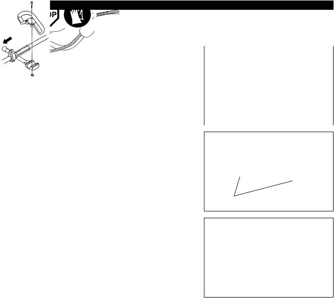
Personal protective equipment
–The clothing worn should be functional and appropriate, i.e. it should be tightfitting but not cause hindrance. Do not wear either jewelry or clothing which could become entangled with bushes or shrubs.
–In order to avoid either head-, eye-, hand-or foot injuries as well as to protect your hearing the following protective equipment and protective clothing must be used during operation of the Brush Cutter/String trimmer.
–Always wear a helmet where there is a risk of falling objects. The protective helmet (1) is to be checked at regular intervals for damage and is to be replaced at the latest after 5 years. Use only approved protective helmets.
–The visor (2) of the helmet (or alternatively goggles) protects the face from flying debris and stones. During operation of the Brush Cutter/String trimmer always wear goggles, or a visor to prevent eye injuries.
–Wear adequate noise protection equipment to avoid hearing impairment (ear muffs (3), ear plugs etc.).
–The work overalls (4) protect against flying stones and debris. We strongly recommend that the user wears work overalls.
–Special gloves (5) made of thick leather are part of the prescribed equipment and must always be worn during operation of the Brush Cutter/String trimmer.
–When using the Brush Cutter/String trimmer, always wear sturdy shoes (6) with a non-slip sole. This protects against injuries and ensures a good footing.
Starting up the brush cutter
–Please make sure that there are no children or other people within a working range of 15 meters (49ft), also pay attention to any animals in the working vicinity.
–Before use always check that the Brush Cutter/String trimmer is safe for operation:
Check the security of the cutting tool, the control lever for easy action and check for proper functioning of the control lever lock.
–Rotation of the cutting tool during idling speed is not allowed. Check with your dealer for adjustment if in doubt. Check for clean and dry handles and test the function of the start/stop switch.
Diagrammatic figure
15 Meter
2

Start the Brush Cutter/String trimmer only in accordance with the instructions. Do not use any other methods for starting the engine!
–Use the Brush Cutter/String trimmer and the tools only for such applications as specified.
–Only start the Brush Cutter/String trimmer engine, after the entire assembly is done. Operation of the device is only permitted after all the appropriate accessories are attached!
–Before starting make sure that the cutting tool has no contact with hard objects such as branches, stones etc. as the cutting tool will revolve when starting.
–The engine is to be switched off immediately in case of any engine problems.
–Should the cutting tool hit stones or other hard objects, immediately switch off the engine and inspect the cutting tool.
–Inspect the cutting tool at short regular intervals for damage (detection of hairline cracks by means of tapping-noise test).
–Operate the Brush Cutter/String trimmer only with the shoulder strap attached which is to be suitably adjusted before putting the Brush Cutter/ String trimmer into operation. It is essential to adjust the shoulder strap according to the user’s size to prevent fatigue occurring during use. Never hold the cutter with one hand during use.
–During operation always hold the Brush Cutter/String trimmer with both hands.
Always ensure a safe footing.
–Operate the Brush Cutter/String trimmer in such a manner as to avoid inhalation of the exhaust gases. Never run the engine in enclosed rooms (risk of gas poisoning). Carbon monoxide is an odorless gas.
–Switch off the engine when resting and when leaving the Brush Cutter/ String trimmer unattended, and place it in a safe location to prevent danger to others or damage to the machine.
–Never put the hot Brush Cutter/String trimmer onto dry grass or onto any combustible materials.
–The cutting tool has to be equipped with it’s appropriate guard. Never run the cutter without this guard!
–All protective installations and guards supplied with the machine must be used during operation.
–Never operate the engine with faulty exhaust muffler.
–Shut off the engine during transport.
–During transport over long distances the tool protection included with the equipment must always be used.
–Ensure safe position of the Brush Cutter/String trimmer during car transportation to avoid fuel leakage.
–When transporting the Brush Cutter/String trimmer, ensure that the fuel tank is completely empty.
–When unloading the Brush Cutter/String trimmer from the truck, never drop the Engine to the ground or this may severely damage the fuel tank.
–Except in case of emergency, never drop or cast the Brush Cutter/String trimmer to the ground or this may severely damage the Brush Cutter/String trimmer.
–Remember to lift the entire equipment from the ground when moving the equipment. Dragging the fuel tank is highly dangerous and will cause damage and leakage of fuel, possibly causing fire.
Refuelling
–Shut off the engine during refuelling, keep away from open flames and do not smoke.
–Avoid skin contact with mineral oil products. Do not inhale fuel vapor. Always wear protective gloves during refuelling. Change and clean protective clothing at regular intervals.
–Take care not to spill either fuel or oil in order to prevent soil contamination (environmental protection). Clean the Brush Cutter/String trimmer immediately after fuel has been spilt.
–Avoid any fuel contact with your clothing. Change your clothing instantly if fuel has been spilt on it (to prevent clothing catching fire).
–Inspect the fuel cap at regular intervals making sure that it can be securely fastened and does not leak.
–Carefully tighten the fuel tank cap. Change location to start the engine (at least 3 meters away from the place of refuelling).
–Never refuel in closed rooms. Fuel vapors accumulate at ground lever (risk of explosions).
–Only transport and store fuel in approved containers. Make sure the fuel stored is not accessible to children.
•Resting
•Transport
•Refuelling
•Maintenance
•Tool Replacement
|
s |
|||||
|
r |
|||||
|
e |
|||||
|
t |
|||||
|
e |
|||||
|
3 |
m |
||||
3

Method of operation
–Only use the Brush cutter/String trimmer in good light and visibility. During the winter season beware of slippery or wet areas, ice and snow (risk of slipping). Always ensure a safe footing.
–Never cut above waist height.
–Never stand on a ladder and run the Brush cutter/String trimmer.
–Never climb up into trees to perform cutting operation with the Brush cutter/ String trimmer.
–Never work on unstable surfaces.
–Remove sand, stones, nails etc. found within the working range. Foreign particles may damage the cutting tool and can cause dangerous kick-backs.
–Before commencing cutting, the cutting tool must have reached full working speed.
Kickback
–When operating the brush cutter, uncontrolled kickback may occur.
–This is particularly the case when attempting to cut within a blade segment between 12 and 2 o’clock.
–Never apply the brush cutter within a segment between 12 and 2 o’clock.
–Never apply this segment of the brush cutter blade to solids, such as bushes and trees, etc., having a diameter in excess of 3 cm or the brush cutter will be deflected at great force with the risk of injuries.
Kickback prevention
To avoid kickbacks, observe the following:
–Operation within a blade segment between 12 and 2 o’clock presents positive hazards, especially when using metal cutting tools.
–Cutting operations within a blade segment between 11 and 12 o’clock, and between 2 and 5 o’clock, must only be performed by trained and experienced operators, and then only at their own risk.
Easy cutting with almost no kickback is possible within a blade segment between 8 and 11 o’clock.
Cutting Tools
Employ only the correct cutting tool for the job in hand.
MS-250.4, MS-251.4 with cutter blade (Star Blade (4 teeth), Eddy Blade (8 teeth)), Nylon cutting head
For cutting thick materials, such as weed, high grass, bushes, shrubs, underwood, thicket etc. (max. 2 cm dia. thickness). Perform this cutting work by swinging the brush cutter evenly in half-circles from right to left (similar to using a scythe).
Maintenance instructions
–The condition of the cutter, in particular of the cutting tool of the protective devices and also of the shoulder strap must be checked before commencing work. Particular attention is to be paid to the cutting blades which must be correctly sharpened.
–Turn off the engine and remove spark plug connector when replacing or sharpening cutting tools, and also when cleaning the cutter or cutting tool.
Caution:
Kickback
Diagrammatic flgure
Diagrammatic flgure
4

Never straighten or weld damaged cutting tools.
–Operate the Brush cutter/Grass trimmer with as little noise and contamination as possible. In particular check the correct setting of the carburetor.
–Clean the Brush cutter/Grass trimmer at regular intervals and check that all screws and nuts are well tightened.
–Never service or store the Brush cutter/Grass trimmer in the vicinity of naked flames.
–Always store the Brush cutter/Grass trimmer in locked rooms and with an emptied fuel tank.
Observe the relevant accident prevention instructions issued by the relevant trade associations and by the insurance companies. Do not perform any modifications on the Brush cutter/Grass trimmer as this will endanger your safety.
The performance of maintenance or repair work by the user is limited to those activities as described in the instruction manual. All other work is to be done by an Authorized Service Agent. Use only genuine spare parts and accessories released and supplied by DOLMAR. Use of non-approved accessories and tools means increased risk of accidents.
DOLMAR will not accept any liability for accidents or damage caused by the use of non-approved cutting tools and fixing devices of cutting tools, or accessories.
First Aid
In case of accident make sure that a first-aid box is available in the vicinity of the cutting operations. Immediately replace any item taken from the first aid box.
When asking for help, please give the following information:
–Place of accident
–What happened
–Number of injured persons
–Kind of injuries
–Your name
Packaging
The DOLMAR Brush cutter/Grass trimmer will be delivered in two protective cardboard boxes to prevent transport damage. Cardboard is a basic raw material and is therefore consequently reusable or suitable for recycling (waste paper recycling).
5

TECHNICAL DATA MS-250.4, MS-251.4
|
MS-251.4 |
MS-250.4 |
||||
|
Model |
|||||
|
Loop handle |
U handle |
||||
|
Dimensions : length x width x height (without cutting blade) |
mm |
1760x330x265 |
1760x600x405 |
||
|
Mass (without plastic guard and cutting blade) |
kg |
5.2 |
5.4 |
||
|
Volume (fuel tank) |
L |
0.5 |
|||
|
Volume (oil tank) |
L |
0.08 |
|||
|
Engine displacement |
cc |
24.5 |
|||
|
Maximum engine performance |
HP |
0.885 at 7000 /min |
|||
|
Engine speed at recommended max. spindle speed |
/min |
8500 |
|||
|
Maximum spindle speed (corresponding) |
/min |
6500 |
|||
|
Maximum fuel consumption |
kg/h |
0.33 |
|||
|
Maximum specific fuel consumption |
g/HPh |
304 |
|||
|
Idling speed |
/min |
3000 |
|||
|
Clutch engagement speed |
/min |
3750 |
|||
|
Carburetor |
type |
WALBRO WYL |
|||
|
Ignition system |
type |
Solid state ignition |
|||
|
Spark plug |
type |
NGK CMR6A |
|||
|
Electrode gap |
mm |
0.7 — 0.8 |
|||
|
Fuel |
Automobile gasoline |
||||
|
Engine Oil |
SAE 10W-30 oil of API Ciassification, |
||||
|
Class SF or higher (4-stroke engine for automobile) |
|||||
|
Gear ratio |
14/19 |
||||
6

DESIGNATION OF PARTS
MS-250.4
Brush Cutter

MS-251.4
String trimmer
21


|
GB |
DESIGNATION OF PARTS |
||||
|
1 |
Fuel Tank |
||||
|
2 |
Rewind Starter |
||||
|
3 |
Air Cleaner |
||||
|
4 |
I-O Switch (on/off) |
||||
|
5 |
Spark Plug |
||||
|
6 |
Exhaust Muffler |
||||
|
7 |
Clutch Case |
||||
|
8 |
Rear Grip |
||||
|
9 |
Hanger |
||||
|
10 |
Handle |
||||
|
11 |
Control Lever |
||||
|
24 |
12 |
Control Cable |
|||
|
13 |
Shaft |
||||
|
14 |
Protector |
||||
|
25 |
15 |
Gear Case/Head Case |
|||
|
16 |
Handle Holder |
||||
|
17 |
Cutter Blade |
||||
|
18 |
Nylon Cutting Head |
||||
|
20 |
Fuel Filler Cap |
||||
|
21 |
Starter Knob |
||||
|
24 |
Exhaust Pipe |
||||
|
25 |
Oil Gauge |
||||
7
MOUNTING OF HANDLE
CAUTION: Before doing any work on the brush cutter, always stop the engine and pull the spark plug connector off the spark plug.
Always wear protective gloves!
CAUTION: Start the brush cutter only after having assembled it completely.
For machines with U Handle models
–Insert the handle bar into the handle holder, making sure that the boss in the handle holder fits into the hole in the handle.
–After the handle bar is in place, tighten the four bolts (M5 x 25).
NOTE: Be sue the bolts are tight, but do not overtighten.
–Fit the control cable (together with the earth cord) to the handle with two clips
(3).
–Avoid any tendency of the control cable to loop at the handle bar.
For machines with Loop Handle
–Fix a barrier to the left side of the machine together with the handle for operator’s protection.
–Do not adjust position of the loop handle too close to the control grip. Keep not less than 250mm distance between the handle and the grip.
(a distance collar is provided for this purpose.)
|
e |
||
|
in |
||
|
g |
||
|
n |
||
|
to |
e |
|
(3)
to engine
8

MOUNTING OF PROTECTOR
To meet the applicable safety provisions, only the tool/ protector combinations as indicated in the table must be used.
Be sure to use genuine DOLMAR cutter blades or nylon cutting head.
–The cutter blade must be well polished, free of cracks or breakage. If the cutter blade hits against a stone during operation, stop the engine and check the blade immediately.
–Polish or replace the cutter blade every three hours of operation.
–If the nylon cutting head hits against a stone during operation, stop the engine and check the nylon cutting head immediately.
CAUTION : The appropriate protector must always be installed, for your own safety and in order to comply with accident-prevention regulations.
Operation of the equipment without the guard being in place is not permitted.
For MS-250.4
|
MS-250.4 |
|
|
Protector for metal blades |
|
|
Star Blade |
Protector for metal blades (Use of protector for metal |
|
blade/cord cutter) |
|
MS-251.4 |
|
|
Protector for cord cutter |
|
|
Nylon cutting head |
Protector for cord cutter (Use of protector for metal |
|
blade/cord cutter) |
–The outside diameter of the cutter blade must be 230mm (9-1/16″). Never use any blades surpassing 230mm (9-1/16″) in outside diameter.
For MS-250.4, MS-251.4
–Install the clamp (3) on the shaft so that the projection of the clamp (3) is inserted into the opening between the gear case (1) and the shaft. Secure the protector (4) with the installation bolts M6 x 30 (2) and screw M5 x 8 (5).
|
Use of protector for metal blade / cord cutter. |
(2) |
(3) |
(1) |
–In use of the metal blade, fasten the protector (4) to the clamp (3) with two bolts M6 x 30 (2).
NOTE : Tighten the right and left bolts evenly so that the gap between the clamp (3) and the protector (4) will be constant.
Otherwise, the protector sometimes may not function as specified.
(4)
|
– In use of the cord cutter, insert the protector (2) into the protector (1), and |
(1) |
(3) |
|
fasten them with two screw (4) and two nuts (3). |
(2)
(4)
9
![]()
MOUNTING OF CUTTER BLADE OR NYLON CUTTER HEAD
Turn the machine upside down, and you can replace the cutter blade easily.
For MS-250.4, MS-251.4
–Insert the hex wrench through the hole in the gear case and rotate the receiver washer (3) until it is locked with the hex wrench.
–Loosen the nut (1) (left-hand thread) with the socket wrench and remove the nut (1), and clamp washer (2).
For MS-250.4 with the hex wrench still in place.
–Mount the cutter blade onto the shaft so that the guide of the receiver washer
(3)fits in the arbor hole in the cutter blade. Install the clamp washer (2) and secure the cutter blade with the nut (1).
[Tightening torque: 13 — 23 N-m]
NOTE: Always wear gloves when handling the cutter blade.
NOTE: The cutter blade-fastening nut (with spring washer) is a consumable
part. If there appears any wear or deformation on the spring washer, Hex wrench replace the nut.
Mounting of nylon cutting head
For MS-251.4
–To install the nylon cutting head (7), remove the tightening nut (8).
–Insert the socket-head wrench (11) through the hole in the gear case and tum the support washer until it will be locked with its notch (12) (or the shaft will be locked).
–Then screw the nylon cutting head onto the shaft by turning it counterclockwise.
–Remove the socket-head wrench.
–Make sure that the blade is the left way up.
Rotation
10

BEFORE START OF OPERATION
Inspection and Refill of Engine Oil
–Perform the following procedure, with the engine cooled down.
–While keeping the engine level, remove the oil gauge, and confirm that the oil is filled within the upper and lower limit marks.
When the oil is in short in such a way that the oil gauge touches the oil only by its tip, in particular with the oil gauge remaining inserted in the crankcase without screwing-in (Fig. 1), refill new oil near the port (Fig. 2).
–For reference, the oil refill time is about 10h (10 times or 10 tanks of oil refill).
–If the oil changes in color or mixes with dirt, replace it with new one. (For the interval and method of replacement, refer to P 17)
Recommended oil: SAE 10W-30 oil of API Classification, Class SF or higher (4-stroke engine for automobile)
|
Oil volume: |
Approx. 0.08L |
Note: If the engine is not kept upright, oil may go into around the engine, and may be refilled excessively.
If the oil is filled above the limit, the oil may be contaminated or may catch fire with white.
Point 1 in Replacement of Oil “Oil Gauge”
–Remove dust or dirt near the oil refill port, and detach the oil gauge.
–Keep the detached oil gauge free of sand or dust. Otherwise, any sand or dust adhering to the oil gauge may cause irregular oil circulation or wear on the engine parts, which will result in troubles.
–As an example to keep the oil gauge clean, it is recommended to insert the oil gauge on its knob side into the engine cover, as shown in Fig.3.
Upper limit
(Edge of oil refill port)
If oil adheres around this tip, refill new oil.
Oil gauge
Fig.3
11

(1) Keep the engine level, and detach the oil gauge.
(2)Fill oil up to the edge of the oil refill port. (Refer to Fig.2 of the preceding page).
Feed oil with the lubricant refill container.
(3)Securely tighten the oil gauge. Insufficient tightening may cause oil leakage.
Point 2 in Replacement of Oil: “If oil spills out”
–If oil spills out between the fuel tank and engine main unit, the oil is sucked into through the cooling air intake port, which will contaminate the engine. Be sure to wipe out spilt oil before start of operation.
REFUELING
Handling of Fuel
It is necessary to handle fuel with utmost care. Fuel may contain substances similar to solvents. Refueling must be performed in a sufficiently ventilated room or in the open air. Never inhale fuel vapor, and keep fuel away from you. If you touch fuel repeatedly or for a long time, the skin becomes dry, which may cause skin disease or allergy. If fuel enters into the eye, clean the eye with fresh water. If your eye remains still irritated, consult your doctor.
Storage Period of Fuel
Fuel should be used up within a period of 4 weeks, even if it is kept in a special container in a well-ventilated shade. If a special container is not used or if the container is not covered, fuel may deteriorate in one day.
STORAGEOFMACHINEAND REFILLTANK
Keep the machine and tank at a cool place free from direct sunshine.Never keep the fuel in the cabin or trunk.
Fuel
The engine is a four-stroke engine. Be sure to use an automobile gasoline (regular gasoline or premium gasoline).
Points for Fuel
–Never use a gasoline mixture which contains engine oil. Otherwise, it will cause excessive carbon accumulation or mechanical troubles.
–Use of deteriorated oil will cause irregular startup.
Refueling
WARNING: INFLAMMABLES STRICTLY PROHIBITED
Gasoline used: Automobile gasoline (unleaded gasoline)
–Loosen the tank cap a little so that there will be no difference in atmospheric pressure.
–Detach the tank cap, and refuel, discharging air by tilting the fuel tank so that the refuel port will be oriented upward. (Never refill fuel full to the oil refill port.)
–Wipe well the periphery of the tank cap to prevent foreign matter from entering into the fuel tank.
–After refueling, securely tighten the tank cap.
●If there is any flaw or damage on the tank cap, replace it.
●The tank cap is consumable, and therefore should be renewed every two to three years.
Fuel tank cap
Fuel upper limit
Fuel tank
12

CORRECT HANDLING OF MACHINE
Attachment of shoulder strap
–Adjust the strap length so that the cutter blade will be kept parallel with the ground.
Detachment
For MS-251.4
–In an emergency, push the notches (1) at both sides, and you can detach the machine from you.
Be extremely careful to maintain control of the machine at this time. Do not allow the machine to be deflected toward you or anyone in the work vicinity.
WARNING: Failure to maintain complete control of the machine at all could result in serious bodily injury or DEATH.
Hanger
For MS-250.4
–In case of emergency, remove the emergency detachment lever (2) by pulling strongly with a finger. The machine sill detach from body.
Be extremely careful to maintain control of the machine at this time. Do not
|
allow the machine to be deflected toward you or |
anyone in the work |
|
vicinity. |
(2) |
WARNING: Failure to maintain complete control of the machine at all could result in serious bodily injury or DEATH.
Hanger
POINTS IN OPERATION AND HOW TO STOP
Observe the applicable accident prevention regulations!
STARTING
Move at least 3m away from the place of refuelling. Place the brush cutter on a clean piece of ground taking care that the cutting tool does not come into contact with the ground or any other objects.
|
A:Cold start |
Throttle control dial |
1) Set this machine on a flat space.
I-O switch (1)
Throttle lever (6)
OPERATION
High speed
13

For machine with U Handle or Loop Handle
1)Set the I-O switch (1) to OPERATION.
2)Choke lever
Close the choke lever. Choke opening:
–Full closing in cold or when the engine is cold.
–Full or half opening in restart just after stop of operation.
3)Primer pump
Continue to push the primer pump until fuel enters into the primer pump. (In general, fuel enters into the primer pump by 7 to 10 pushes.)
If the primer pump is pushed excessively, an excess of gasoline returns to the fuel tank.
4)Recoil starter
–Pull the start knob gently until it is hard to pull (compression point). Then, return the start knob, and pull it strongly.
–Never pull the rope to the full. Once the start knob is pulled, never release your hand immediately. Hold the start knob until it returns to its original point.
5)Choke lever
When the engine starts, open the choke lever.
–Open the choke lever progressively while checking the engine operation. Be sure to open the choke lever to the full in the end.
–In cold or when the engine is cooled down, never open the choke lever suddenly. Otherwise, the engine may stop.
6)Warm-up operation
Continue warm-up operation for 2 to 3 minutes.
CLOSE
Carburetor
Primer Pump
OPEN
Note: – If the starter handle is pulled repeatedly when the choke lever remains at “START” position, the engine will not start easily due to excessive fuel intake.
–In case of excessive fuel intake, remove the spark plug and pull the starter handle slowly to remove excess fuel. Also, dry the electrode section of the spark plug.
Caution during operation:
If the throttle lever is opened fully in a no-load operation, the engine rotation is increased to 10,000/min or more. Never operate the engine at a higher speed than required and at an approximate speed of 6,000 — 8,500/min.
14

B: Startup after warm-up operation
1)Push the primer pump repeatedly.
2)Keep the throttle lever at the idling position.
3)Pull the recoil starter strongly.
4)If it is difficult to start the engine, open the throttle by about 1/3. Pay attention to the cutter blade which may rotate.
Attention in Operation
When the engine is operated upside down, white smoke may come out from the muffler.
STOPPING
STOP
1)Release the throttle lever (6) fully, and when the engine rpm has lowered, set the I-O switch to STOP the engine will now stop.
2)Be aware that the cutting head may not stop immediately and allow it to slow down fully.
I-O switch (1)
Throttle lever (6)
ADJUSTMENT OF LOW-SPEED ROTATION (IDLING)
When it is necessary to adjust the low-speed rotation (idling), perform it by the carburetor adjusting screw.
CHECKUPOF LOW-SPEEDROTATION
–Set the low-speed rotation to 3000/min.
If it is necessary to change the rotation speed, regulate the adjusting screw (illustrated on the left), with Phillips screwdriver.
–Turn the adjusting screw to the right, and the engine rotation will increase. Turn the adjusting screw to the left, and the engine rotation will drop.
–The carburetor is generally adjusted before shipment. If it is necessary to readjust it, please contact Authorized Service Agent.
Adjusting screw
Carburetor
RESHARPENING THE CUTTING TOOL
CAUTION : The cutting tools mentioned below must only be resharpened by an authorized facility. Manual resharpening will result in imbalances of the cutting tool causing vibrations and damage to the equipment.
–cutter blade (star blade (4 teeth), eddy blade (8 teeth))
An expert resharpening and balancing service is provided by Authorized Service Agents.
NOTE : To increase the service life of the cutter blade (star blade, eddy blade) it may be turned over once, until both cutting edges have become blunt.
15

NYLON CUTTING HEAD
The nylon cutting head is a dual string trimmer head capable of both automatic and bump & feed mechanisms.
The nylon cutting head will automatically feed out the proper length of nylon cord by the changes in centrifugal force caused by increasing or decreasing rpms. However, to cut soft grass more efficiently, bump the nylon cutting head against the ground to feed out extra cord as indicated under operation section.
Operation
–Increase the nylon cutting head speed to approx. 6,000/min.
Low speed (under 4,800/min) is not suitable, the nylon cord will not feed out properly at low speed.
–The most effective cutting area is shown by the shaded area.
If the nylon cord does not feed out automatically proceed as follows:
1.Release the throttle lever to run the engine idle and then squeeze the throttle lever fully. Repeat this procedure until the nylon cord feeds out to the proper length.
2.If the nylon cord is too short to feed out automatically with the above procedure, bump the knob of the nylon cutting head against the ground to feed out the nylon cord.
3.If the nylon cord does not feed out with procedure 2, rewind/replace the nylon cord by following the procedures described under “Replacing the nylon cord”.
Replacing the nylon cord
–First, stop the engine.
–Press on the housing latches inward to lift off the cover, then remove the spool.
–Hook the center of new nylon cord into the notch in the center of the spool, with one end of the cord extending about 80mm (3-1/8″) more than the other. Then wind both ends firmly around the spool in the direction of the head rotation (left-hand direction indicated by LH and right-hand direction by RH on the side of the spool).
–Wind all but about 100mm (3-15/16″) of the cords, leaving the ends temporarily hooked through a notch on the side of the spool.
–Mount the spool in the housing so that the grooves and protrusions on the spool match up with those in the housing. Keep the side with letters on the spool visible on the top. Now, unhook the ends of the cord from their temporary position and feed the cords through the eyelets to come out of the housing.
Most effective cutting area
Knob
|
Cover |
|
|
Latches |
|
|
Press |
Press |
For left hand rotation
Spool
100mm(3-15/16”)
Notches
Eyelets
16

–Align the protrusion on the underside of the cover with the slots of the eyelets.
Then push cover firmly onto the housing to secure it.
Cover
Protrusion
Slot of eyelet
SERVICING INSTRUCTIONS
CAUTION : Before doing any work on the Brush cutter/String trimmer, always stop the engine and pull the plug cap off the spark plug (see “checking the spark plug”).
Always wear protective gloves!
To ensure a long service life and to avoid any damage to the equipment, the following servicing operations should be performed at regular intervals.
Daily checkup and maintenance
–Before operation, check the machine for loose screws or missing parts. Pay particular attention to the tightness of the cutter blade or nylon cutting head.
–Before operation, always check for clogging of the cooling air passage and the cylinder fins. Clean them if necessary.
–Perform the following work daily after use:
•Clean the Brush cutter/String trimmer externally and inspect for damage.
•Clean the air filter. When working under extremely dusty conditions, clean the filter the severall times a day.
•Check the blade or the nylon cutting head for damage and make sure it is firmly mounted.
•Check that there is sufficient difference between idling and engagement speed to ensure that the cutting tool is at a standstill while the engine is idling (if necessary reduce idling speed).
If under idling conditions the tool should still continue to run, consult your nearest Authorized Service Agent.
–Check the functioning of the I-O switch, the lock-off lever, the control lever, and the look button.
REPLACEMENT OF ENGINE OIL
Deteriorated engine oil will shorten the life of the sliding and rotating parts to a great extent. Be sure to check the period and quantity of replacement.
ATTENTION : In general, the engine main unit and engine oil still remain hot just after the engine is stopped. In replacement of oil, confirm that the engine main unit and engine oil are sufficiently cooled down. Otherwise, there may remain a risk of scald.
Note: If the oil filled above the limit, it may be contaminated or may catch fire with white smoke.
Interval of replacement : Initially, every 20 operating hours, and subsequently every 50 operating hours Recommended oil : SAE10W-30 oil of API Classification SF Class or higher (4-stroke engine oil for automobile)
|
In replacement, perform the following procedure. |
Fuel tank cap |
1)Confirm that the tank cap is tightened securely.
2)Detach the oil gauge.
Keep the oil gauge free from dust or dirt.
Oil gauge
17

3) Place waste or paper near the oil refill port.
Waste or paper
4)Detach the oil gauge, and drain oil, tilting the main unit toward the oil refill port.
Drain oil in a container.
5)Keep the engine level, and feed new oil up to the edge of the oil refill port. In refill, use a lubricant refill container.
6)After refill, securely tighten the oil gauge. Insufficient tightening of the oil gauge will lead to oil leakage.
POINTS ON OIL
–Never discard replaced engine oil in garbage, earth or sewage ditch. Disposal of oil is regulated by law. In disposal, always follow the relevant laws and regulations. For any points remaining unknown, contact Authorized Service Agent.
–Oil will deteriorate even when it is kept unused. Perform inspection and replacement at regular intervals (replace with new oil every 6 months).
CLEANING OF AIR CLEANER
DANGER:INFLAMMABLESSTRICTLYPROHIBITED
Interval of Cleaning and Inspection: Daily (every 10 operating hours)
–Turn the choke lever to the full close side, and keep the carburetor off from dust or dirt.
–Remove the air cleaner cover-fixing bolts.
–Pull the cover lower side and detach the air cleaner cover.
–If oil adheres to the element (sponge), squeeze it firmly.
–For heavy contamination:
1)Remove the element (sponge), immerse it in warm water or in water-diluted neutral detergent, and dry it completely.
2)Clean the element (felt) with gasoline, and dry it completely.
–Before attaching the element, be sure to dry it completely. Insufficient drying of the element may lead to difficult startup.
–Wipe out with waste cloth, oil adhering around the air cleaner cover and plate breather.
–Immediately after cleaning is finished, attach the cleaner cover and tighten it with fixing bolts. (In remounting, first place the upper claw, and then the lower claw.)
Points in Handling Air Cleaner Element
–Clean the element several times a day, if excessive dust adheres to it.
–If operation continues with the element remaining not cleared of oil, oil in the air cleaner may fall outside, resulting in oil contamination.
Plate
Element (sponge)
Air cleaner cover
Breather Part
Element (felt)
Fixing bolt
Pick this part and remove the element (felt).
18

CHECKING THE SPARK PLUG
–Only use the supplied universal wrench to remove or to install the spark plug.
–The gap between the two electrodes of the spark plug should be 0.7-0.8mm (0.028”-0.032”). If the gap is too wide or too narrow, adjust it. If the spark plug is clogged with carton or fouled, clean it thoroubhly or replace it.
CAUTION : Never touch the spark plug connector while the engine is running (danger of high voltage electric shock).
SUPPLY OF GREASE TO GEAR CASE
–Supply grease (Shell Alvania 2 or equivalent) to the gear case through the grease hole every 30 hours. (Genuine DOLMAR grease may be purchased from your DOLMAR dealer.)
CLEANING OF FUEL FILTER
WARNING: INFLAMMABLES STRICTLY PROHIBITED
Interval of Cleaning and Inspection: Monthly (every 50 operating hours)
Suction head in the fuel tank
–The fuel filler (1) of the suction head is used to filler the fuel required by the carburetor.
–A periodical visual inspection of the fuel filter is to be conducted. For that purpose open the tank cap, use a wire hook and pull out the suction head through the tank opening. Filters found to have hardened, been polluted or clogged up are to be replaced.
–Insufficient fuel supply can result in the admissible maximum speed being exceeded. It is therefore important to replace the fuel filter at least quarterly to ensure satisfactory fuel supply to the carburetor.
REPLACEMENT OF FUEL PIPE
CAUTION: INFLAMMABLES STRICTLY PROHIBITED
Interval of Cleaning and Inspection: Daily (every 10 operating hours) Replacement: Annually (every 200 operating hours)
Replace the fuel pipe every year, regardless of operating frequency. Fuel leakage may lead to fire.
If any leakage is detected during inspection, replace the oil pipe immediately.
0.7mm-0.8mm (0.028”-0.032”)
Gear case
Grease hole
Fuel pipe
House clamp
Fuel
filter(1)
Fuel pipe
INSPECTION OF BOLTS, NUTS AND SCREWS
–Retighten loose bolts, nuts, etc.
–Check for fuel and oil leakage.
–Replace damaged parts with new ones for safety operation.
CLEANING OF PARTS
–Keep the engine always clean.
–Keep the cylinder fins free of dust or dirt. Dust or dirt adhering to the fins will cause seizure.
REPLACEMENT OF GASKETS AND PACKINGS
In reassembling after the engine is dismounted, be sure to replace the gaskets and packings with new ones.
Any maintenance of adjustment work that is not included and described in this manual is only to be performed by Authorized Service Agents.
19
![]()
STORAGE
WARNING: When draining the fuel, be sure to stop the engine and confirm that the engine cools down.
Just after stopping the engine, it may still hot with possibility of burns, inflammability and fire.
ATTENTION: When the machine is kept out of operation for a long time, drain up all fuel from the fuel tank and carburetor, and keep it at a dry and clean place.
–Drain up fuel from the fuel tank and carburetor according to the following procedure:
1)Remove the fuel tank cap, and drain fuel completely.
If there is any foreign matter remaining in the fuel tank, remove it completely.
2)Pull out the fuel filter from the refill port using a wire.
|
3) Push the primer pump until fuel is drained from there, and drain fuel |
Drain fuel |
Humidity |
|
coming into the fuel tank. |
||
4)Reset the filter to the fuel tank, and securely tighten the fuel tank cap.
5)Then, continue to operate the engine until it stops.
–Remove the spark plug, and drip several drops of engine oil through the spark plug hole.
–Gently pull the starter handle so that engine oil will spread over the engine, and attach the spark plug.
–Attach the cover to the cutter blade.
–During storage, keep the rod horizontal or keep the machine upright with the blade edge oriented upward. (In this case, pay full attention to prevent the machine from falling.)
Never store the machine with the cutter blade edge oriented downward. Lubricating oil may spill out.
–Keep the drained fuel in a special container in a well-ventilated shade.
Attention after long-time storage
–Before startup after long-time shutdown, be sure to replace oil (refer to P 17). Oil will deteriorate while the machine is kept out of operation.
Fault location
|
Fault |
System |
Observation |
Cause |
|
Engine not starting or with |
Ignition system |
Ignition spark O.K. |
Fault in fuel supply or compression system, mechanical |
|
difficulty |
defect |
||
|
No ignition spark |
STOP-switch operated, wiring fault or short circuit, spark |
||
|
plug or connector defective, ignition module faulty |
|||
|
Fuel supply |
Fuel tank filled |
Incorrect choke position, carburetor defective, fuel supply |
|
|
line bent or blocked, fuel dirty. |
|||
|
Compression |
No compression when |
Cylinder bottom gasket defective, crankshaft seals |
|
|
pulled over |
damaged, cylinder or piston rings defective or improper |
||
|
sealing of spark plug |
|||
|
Mechanical fault |
Starter not engaging |
Broken starter spring, broken parts inside of the engine |
|
|
Warm start problems |
Tank filled ignition spark |
Carburetor contaminated, have it cleaned |
|
|
existing |
|||
|
Engine starts but dies |
Fuel supply |
Tank filled |
Incorrect idling adjustment, carburetor contaminated |
|
Fuel tank vent defective, fuel supply line interrupted, |
|||
|
cable or STOP-switch faulty |
|||
|
Insufficient performance |
Several systems |
Engine idling poor |
Air filter contaminated, carburetor contaminated, muffler |
|
may simultaneously |
clogged, exhaust duct in the cylinder clogged |
||
|
be affected |
|||
20

|
Operating time |
Before |
After |
Daily |
Shutdown |
Corres-po |
|||||
|
30h |
50h |
200h |
||||||||
|
operation |
lubrication |
(10h) |
/rest |
nding P |
||||||
|
Item |
||||||||||
|
Inspect/clean |
○ |
11 |
||||||||
|
Engine oil |
||||||||||
|
Replace |
○*1 |
17 |
||||||||
|
Tightening parts |
Inspect |
○ |
19 |
|||||||
|
(bolt, nut) |
||||||||||
|
Clean/inspect |
○ |
― |
||||||||
|
Fuel tank |
||||||||||
|
Drain fuel |
○*3 |
20 |
||||||||
|
Throttle lever |
Check function |
○ |
13 |
|||||||
|
Stop switch |
Check function |
○ |
13 |
|||||||
|
Cutting blade |
Inspect |
○ |
○ |
9 |
||||||
|
Low-speed rotation |
Inspect/adjust |
○ |
15 |
|||||||
|
Air cleaner |
Clean |
○ |
18 |
|||||||
|
Ignition plug |
Inspect |
○ |
19 |
|||||||
|
Cooling air duct |
Clean/inspect |
○ |
19 |
|||||||
|
Inspect |
○ |
19 |
||||||||
|
Fuel pipe |
||||||||||
|
Replace |
*2 |
― |
||||||||
|
Gear-case grease |
Refill |
○ |
19 |
|||||||
|
Fuel filter |
Clean/replace |
○ |
19 |
|||||||
|
Clearance between air intake |
Adjust |
*2 |
― |
|||||||
|
valve and air discharge valve |
||||||||||
|
Engine overhaul |
*2 |
― |
||||||||
|
Carburetor |
Drain fuel |
○*3 |
20 |
*1 Perform initial replacement after 20h operation.
*2 For the 200 operating hour inspection, request Authorized Service Agent or a machine shop. *3 After emptying the fuel tank, continue to run the engine and drain fuel in the carburetor.
21

TROUBLESHOOTING
Before making a request for repairs, check a trouble for yourself. If any abnormality is found, control your machine according to the description of this manual. Never tamper or dismount any part contrary to the description. For repairs, contact Authorized Service Agent or local dealership.
|
State of abnormality |
Probable cause (malfunction) |
Remedy |
||||
|
Failure to operate primer pump |
Push 7 to 10 times. |
|||||
|
Low pulling speed of starter rope |
Pull strongly. |
|||||
|
Lack of fuel |
Feed fuel. |
|||||
|
Clogged fuel filter |
Clean |
|||||
|
Broken fuel tube |
Straighten fuel tube |
|||||
|
Deteriorated fuel |
Deteriorated fuel makes starting more difficult. |
|||||
|
Replace with new one. (Recommended |
||||||
|
replacement: 1 month) |
||||||
|
Excessive suction of fuel |
Set throttle lever from medium speed to high |
|||||
|
speed, and pull starter handle until engine |
||||||
|
starts. Once engine starts, cutter blade |
||||||
|
Engine does not start |
starts rotating. Pay full attention to cutter |
|||||
|
blade. |
||||||
|
If engine will not start still, remove spark plug, |
||||||
|
make electrode dry, and reassemble them as |
||||||
|
they originally are. Then, start as specified. |
||||||
|
Detached plug cap |
Attach securely |
|||||
|
Contaminated spark plug |
Clean |
|||||
|
Abnormal clearance of spark plug |
Adjust clearance |
|||||
|
Other abnormality of spark plug |
Replace |
|||||
|
Abnormal carburetor |
Make request for inspection and maintenance. |
|||||
|
Starter rope cannot be pulled |
Make request for inspection and maintenance |
|||||
|
Abnormal drive system |
Make request for inspection and maintenance |
|||||
|
Insufficient warm-up |
Perform warm-up operation |
|||||
|
Choke lever is set to “CLOSE” although engine |
Set to “OPEN” |
|||||
|
is warmed up |
||||||
|
Engine stops soon |
||||||
|
Clogged fuel filter |
Clean |
|||||
|
Engine speed does not increase |
||||||
|
Contaminated or clogged air cleaner |
Clean |
|||||
|
Abnormal carburetor |
Make request for inspection and maintenance |
|||||
|
Abnormal drive system |
Make request for inspection and maintenance |
|||||
|
Cutter blade does not rotate |
Loosened cutter blade-tightening nut |
Tighten securely |
||||
|
Twigs caught by cutter blade or |
Remove foreign matter |
|||||
|
dispersion-preventing cover |
||||||
|
Stop engine immediately |
Abnormal drive system |
Make request for inspection and maintenance. |
||||
|
Main unit vibrates abnormally. |
Broken, bent or worn cutter blade |
Replace cutter blade |
||||
|
Loosened cutter blade-tightening nut |
Tighten securely |
|||||
|
Shifted convex part of cutter blade and cutter |
Attach securely |
|||||
|
blade support fitting |
||||||
|
Stop engine immediately |
||||||
|
Abnormal drive system |
Make request for inspection and maintenance |
|||||
|
Cutter blade does not stop immediately. |
High idling rotation |
Adjust |
||||
|
Detached throttle wire |
Attach securely |
|||||
|
Stop engine immediately |
||||||
|
Abnormal drive system |
Make request for inspection and maintenance |
|||||
|
Engine does not stop. |
Detached connector |
Attach securely |
||||
|
Abnormal electric system |
Make request for inspection and maintenance. |
|||||
|
Run engine at idling, and set choke |
||||||
|
lever to CLOSE. |
||||||
When the engine does not start after warm-up operation:
If there is no abnormality found for the check items, open the throttle by about 1/3 and start the engine.
22
 Loading…
станки со склада
Курсы валют
22.04.2023
1 USD
81.4863 ₽
1 EUR
89.3495 ₽
1 BYN
27.7381 ₽
100 KZT
17.8843 ₽
100 KGS
93.1059 ₽
100 AMD
21.0304 ₽
10 CNY
118.1110 ₽
Мы поставляем станки по всему миру, в том числе в Россию, Беларусь, Казахстан, Армению и Киргизию, включая город
Гильотина DURMA MS 2504
Цена:
По запросу
Цена с НДС 20%
Цена с НДС 0%
Цена с НДС 0%
Цена с НДС 0%
Цена с НДС 0%
Цена с НДС 0%
Цена с НДС 0%
Перейти в корзину
|
По запросу Цена с НДС 20% Цена с НДС 0% Цена с НДС 0% Цена с НДС 0% Цена с НДС 0% Цена с НДС 0% Цена с НДС 0% |
|
В корзину Быстрый запрос |
|
|
Характеристики
Основные характеристики
1114
Турция
Электрический
2550 мм
4.0 мм
750 мм
1°30′ °
42 рез./мин
800 мм
450 мм
Параметры подключения
Габариты
3200 мм
2300 мм
1350 мм
3230 кг
Описание
Особенности
-
DURMA MS 2504 — это электромеханическая гильотина с прочной сварной рамой, рабочей длиной 2550 мм и толщиной обрабатываемого металла до 4.0 мм;
-
Гильотина оснащена 750 мм моторизованным задним упором с цифровой индикацией;
-
В комплект также входит выносная педаль с кнопкой аварийной остановки;
-
Для удобства позиционирования листа имеется 1 боковой упор и 2 поддерживающих упора.
Рекомендации по применению
-
Гильотины для металла применяется для продольного и поперечного раскроя черного и цветного листового металла, нержавейки и оцинковки, без повреждения поверхности.
* Значение толщины металла (для всех гильотин, кроме Mazanek GM) указано для обычной стали (низкоуглеродистой и углеродистой стали) с пределом кратковременной прочности σВ, который не должен превышать 400 MРa (1 Н/мм2 = 1 MPa). Для работы с материалами, не входящими в группу углеродистых сталей (такие как легированные стали, нержавеющие стали, холоднокатаные стали), необходимо проконсультироваться с сотрудниками компании МОССклад.
Обзор опций
Опционально вы можете установить на гильотину NC-контроллер D-TOUCH-5
Развернуть опции
Свернуть опции
Рекомендуемые товары
Похожие станки
Купите с этим станком
Доставка и оплата
Уважаемые клиенты, ознакомьтесь с вариантами подбора, оплаты, получения и ввода в эксплуатацию товара, а также с гарантийными и другими обязательствами.
Как оплатить?
- Оплата наличными
- Безналичная оплата
- Оплата банковскими картами в нашем магазине станков или дистанционно
- Оплата через Сбербанк Онлайн
- Оплата банковским переводом
- Лизинг и кредит
Как получить?
- Доставка в любой город России и ЕАЭС нашим грузовым транспортом или транспортной компанией
- Доставка экспресс-почтой
- Самовывоз из офиса (до 40 кг.)
- Самовывоз со склада в г. Лобня
Как запустить?
- Самостоятельно согласно инструкции к оборудованию
- Бесплатная пуско-наладка оборудования нашим инженером (вы оплачиваете только проезд и проживание)
- Список подготовительных работ
Важно!
- Гарантийные обязательства
- Заключение договора
- Дополнительная информация
- Политика конфиденциальности
Вопросы и отзывы
Компания «МОССклад» поставляет Гильотина DURMA MS 2504 во все города России, в том числе в г. Москва, Санкт-Петербург, Челябинск, Пермь, Симферополь, Ульяновск, Казань, Калуга, Новосибирск, Екатеринбург, Нижний Новгород, Калининград, Самара, Омск, Уфа, Саратов, Красноярск, Владивосток, Ростов-на-Дону, Воронеж, Волгоград, Махачкала, Грозный и другие, а также в Белоруссию, Казахстан, Армению и Киргизию.
Продажа оборудования осуществляется на условиях 100% оплаты при наличии его на складе и 50% предоплате при покупке под заказ.
Описание
Электромеханические гильотинные ножницы MS 2504 с длиной резки в 2550 мм и толщиной резки 4 мм.
Высокотехнологичная серия станков MS обеспечивает отличные результаты в различных типах работ. Серия MS позволяет вам достичь точности и идеальной резки путем ввода всех значений резки.
Эффективность, максимальная безопасность и точность резки являются отличительными чертами серии MS.
Оборудованный согласно мировым стандартам высокотехнологичный продукт – гильотинные ножницы серии MS — предлагает Вам только самые точные решения.
-
Технология прямого привода
-
Точная резка
-
Легкое программирование
-
Максимальная скорость и безопасность
-
Низкое энергопотребление
Гильотины DURMA серии MS обеспечивают надежное, эффективное и экономичное решение. Знания, умения и опыт стали основой для разработки наших механических и электронных компонентов привода. Производительность и качество продукта никогда не подвергаются риску при изготовлении.
-
Быстрая и высокая точность
-
Безопасная работа
-
Настраиваемые
-
Защита против поломок
-
Не требует обслуживания
Основные функции серии MS
-
Регулируемый угол наклона 0-180 °
-
Настольные шариковые опоры
-
Прижимы с резиной
-
Световая завеса защиты
-
Магнитный тормоз и система сцепления DURMA
Стандартное оборудование гильотинных ножниц MS 2504
-
Стальная конструкция St44 Al и рама для снятия напряжения
-
Легкая регулировка зазора
-
Защита пальцев
-
Прижимы с резиной
-
Ручной задний упор (MS 1303, MS 2003, MS 2525)
-
Моторизованный задний упор с шариковым винтом (MS 2004, MS 2504, MS 3004)
-
Передние встроенные столы (MS 2004, MS 2504, MS 3004)
-
Верхние двусторонние ножи, нижние двусторонние ножи (MS 1303, MS 2003, MS 2525)
-
Верхние двусторонние ножи, нижние двусторонние ножи (MS 2004, MS 2504, MS 3004)
Опциональное оборудование
-
Нормы CE
-
NC Блок управления сенсорным экраном (D-Touch 7)
-
Линия лазерной резки
-
Световая завеса защиты
-
Специальный задний манометр
-
Пневмосистема поддержки тонких листов
-
Устройство для поддержки листа с конвейерной лентой и контейнером
-
Регулируемый ограничитель угла 0-180°
-
Доп. опорные рычаги
-
Специальные ножи
-
Специальная упаковка для импорта
Панель управления D-Touch 7
Простой в использовании интерфейс D-Touch 7 обеспечивает идеальную резку за считанные секунды благодаря пошаговому программированию и вводу параметром материала.
-
Широкий цветной сенсорный экран (LCD 7” 800×480)
-
Быстрый ввод данных
-
Простое подключение
-
USB вход
-
Интернет: RJ-45 10/100M
-
Windows CE
-
Неограниченное количество программ
-
Неограниченное количество типа материала
Быстрый сервис и запасные части
DURMA обеспечивает лучший уровень сервиса, наличием квалифицированного персонала и склада запасных частей. Наши опытные и профессиональные специалисты всегда готовы к Вашим услугам. Наши курсы профессионального обучения работе оборудования и его применения дадут Вам преимущество в использовании нашей техники.
Гильотина с электромеханическим приводом марка ms 2504
Гильотины электромеханические DURMA MS 2504
DURMA c электроприводом серии MS – доступное решение с использованием современных технологий. На данных гильотинах возможна установка числового управления, что значительно облегчает работу и увеличивает производительность гильотины.
- Прочная сварная конструкция
- Телескопический стол или опорные штанги для передней поддержки стали
- Селекторный переключатель для одиночного хода
- Левосторонний упорный рычаг
- Жесткие фиксирующие устройства/пальцевая защита с нескользящей резиновой прокладкой
- Кнопка аварийного останова
Технические характеристики гильотин электромеханических DURMA MS 2504
| Толщина материал, мм | 4 | |
| Длина листа, мм | 2550 | |
| Угол резки | 1,30° | |
| Кол-во резов в минуту | 42 | |
| Размеры, мм | Длина | 3050 |
| Ширина | 2260 | |
| Высота | 1330 | |
| Вес, кг | 3300 | |
| Номинальная мощность мотора, кВт | 7,5 |
- Задние упоры с зубчатой рейкой со счётчиком на 550мм или 750мм обеспечивают идеальную параллельность
- Автоматический зажим с резиновым покрытием, предохраняющим листы от повреждений.
- Педальное управление.
- Цельные реверсивные лезвия.
- Рабочий стол 400мм с левым боковым упором со шкалой.
- Встроенные в передний стол линейки, позволяющие производить измерение спереди.
- Электромеханический задний упор 750 мм с управлением спереди, регулируемым с точностью 0,1мм и позволяющим легко выполнять точные резы.
- Электромеханический задний упор 1000 мм с управлением спереди, регулируемым с точностью 0,1мм и позволяющим легко выполнять точные резы.
- ЧПУ-контроллер ЕNC 100.
- Дополнительные ножи (верхний, нижний), кмпл.
Источник
Гильотины электромеханические DURMA MS 2504

Гильотины электромеханические DURMA MS 2504
DURMA c электроприводом серии MS – доступное решение с использованием современных технологий. На данных гильотинах возможна установка числового управления, что значительно облегчает работу и увеличивает производительность гильотины.
- обработка металлических листов небольшой толщины;
- выпуск металлических кровельных листов;
- производство вентиляционных систем и другой жестяной продукции.
- Прочная сварная конструкция
- Телескопический стол или опорные штанги для передней поддержки стали
- Селекторный переключатель для одиночного хода
- Левосторонний упорный рычаг
- Жесткие фиксирующие устройства/пальцевая защита с нескользящей резиновой прокладкой
- Кнопка аварийного останова
Технические характеристики гильотин электромеханических DURMA MS 2504
| Модель | MS2504 |
| Толщина обрабатываемого материала | 4 |
| Рабочая длина | 2550 |
| Угол реза | 1° 30′ |
| Количество резов в минуту | 42 |
| Мощность двигателя, кВт | 7,5 |
| Ширина стола, мм | 450 |
| Высота стола, мм | 800 |
| Длина заднего упора, мм | 750 |
| Габариты станка (Высота/Ширина/Длина), мм | 1330x 2260x 3050 |
| Вес, кг | 3300 |
- Задние упоры с зубчатой рейкой со счётчиком на 550мм или 750мм обеспечивают идеальную параллельность
- Автоматический зажим с резиновым покрытием, предохраняющим листы от повреждений.
- Педальное управление.
- Цельные реверсивные лезвия.
- Рабочий стол 400мм с левым боковым упором со шкалой.
- Встроенные в передний стол линейки, позволяющие производить измерение спереди.
Технические характеристики модели
Источник
Гильотина с электромеханическим приводом марка ms 2504
Гильотины электромеханические DURMA MS 2504
DURMA c электроприводом серии MS – доступное решение с использованием современных технологий. На данных гильотинах возможна установка числового управления, что значительно облегчает работу и увеличивает производительность гильотины.
- Прочная сварная конструкция
- Телескопический стол или опорные штанги для передней поддержки стали
- Селекторный переключатель для одиночного хода
- Левосторонний упорный рычаг
- Жесткие фиксирующие устройства/пальцевая защита с нескользящей резиновой прокладкой
- Кнопка аварийного останова
Технические характеристики гильотин электромеханических DURMA MS 2504
| Толщина материал, мм | 4 | |
| Длина листа, мм | 2550 | |
| Угол резки | 1,30° | |
| Кол-во резов в минуту | 42 | |
| Размеры, мм | Длина | 3050 |
| Ширина | 2260 | |
| Высота | 1330 | |
| Вес, кг | 3300 | |
| Номинальная мощность мотора, кВт | 7,5 |
- Задние упоры с зубчатой рейкой со счётчиком на 550мм или 750мм обеспечивают идеальную параллельность
- Автоматический зажим с резиновым покрытием, предохраняющим листы от повреждений.
- Педальное управление.
- Цельные реверсивные лезвия.
- Рабочий стол 400мм с левым боковым упором со шкалой.
- Встроенные в передний стол линейки, позволяющие производить измерение спереди.
- Электромеханический задний упор 750 мм с управлением спереди, регулируемым с точностью 0,1мм и позволяющим легко выполнять точные резы.
- Электромеханический задний упор 1000 мм с управлением спереди, регулируемым с точностью 0,1мм и позволяющим легко выполнять точные резы.
- ЧПУ-контроллер ЕNC 100.
- Дополнительные ножи (верхний, нижний), кмпл.
Источник
Гильотины электромеханические DURMA MS 2504


Уточните цену у менеджеров по телефону+7(831) 246-05-27
Готовая продукция:


Гильотинные ножницы Durma серии MS используются для резки листов (листовой металл, алюминий, медь, пластик, бумага и т. д.) Различной толщины и качества. В прошлом гильотинные ножницы с ручным приводом были успешны и широко применялись для раскроя листов, на данный момент использование гильотин с электроприводом является более рациональным решением для раскроя.
Производитель — DURMA Турция
Технические характеристики гильотины электромеханической DURMA 2504
| Толщина материал, мм | 4 | |
| Длина листа, мм | 2550 | |
| Угол резки | 1,30° | |
| Кол-во резов в мин | 42 | |
| Размеры, мм | Длина | 3050 |
| Ширина | 2260 | |
| Высота | 1330 | |
| Вес, кг | 3300 | |
| Номинальная мощность мотора, кВт | 7.5 |
Комплект поставки:
1. Прижим листа с резиновой прокладкой
2. Контрольная панель EZM9910
3. 1 выравнивающая штанга + 2 поддерживающие штанги
5. Переносная ножная педаль с кнопкой аварийной остановки
6. 750 мм моторизированный задний упор с цифровым дисплеем
7. Откидной стопор в Т-пазе в опорной штанге
Система управления:
Широкий цветной сенсорный экран (LCD 7 «800×480)
Источник
Гильотины электромеханические DURMA MS 2504

Гильотины электромеханические DURMA MS 2504
DURMA c электроприводом серии MS – доступное решение с использованием современных технологий. На данных гильотинах возможна установка числового управления, что значительно облегчает работу и увеличивает производительность гильотины.
- обработка металлических листов небольшой толщины;
- выпуск металлических кровельных листов;
- производство вентиляционных систем и другой жестяной продукции.
- Прочная сварная конструкция
- Телескопический стол или опорные штанги для передней поддержки стали
- Селекторный переключатель для одиночного хода
- Левосторонний упорный рычаг
- Жесткие фиксирующие устройства/пальцевая защита с нескользящей резиновой прокладкой
- Кнопка аварийного останова
Технические характеристики гильотин электромеханических DURMA MS 2504
| Модель | MS2504 |
| Толщина обрабатываемого материала | 4 |
| Рабочая длина | 2550 |
| Угол реза | 1° 30′ |
| Количество резов в минуту | 42 |
| Мощность двигателя, кВт | 7,5 |
| Ширина стола, мм | 450 |
| Высота стола, мм | 800 |
| Длина заднего упора, мм | 750 |
| Габариты станка (Высота/Ширина/Длина), мм | 1330x 2260x 3050 |
| Вес, кг | 3300 |
- Задние упоры с зубчатой рейкой со счётчиком на 550мм или 750мм обеспечивают идеальную параллельность
- Автоматический зажим с резиновым покрытием, предохраняющим листы от повреждений.
- Педальное управление.
- Цельные реверсивные лезвия.
- Рабочий стол 400мм с левым боковым упором со шкалой.
- Встроенные в передний стол линейки, позволяющие производить измерение спереди.
Технические характеристики модели
Источник
Электромеханическая гильотина DURMA серии MS 2504


Электромеханическая гильотина DURMA серии MS 2504
Стандартная комплектация:
- специальные площадки с шаровыми опорами
- встроенная защита от повреждения пальцев
- переносная педаль с кнопкой аварийного выключения
- ручной или электромеханический (для моделей 2004-3004) ограничитель глубины подачи листа
- упор для выравнивания листа по краю со шкалой и Т-пазом и две опорные штанги
Дополнительно возможна установка следующих устройств:
- управляемый с фронтальной стороны электромеханический ограничитель подачи листа 1000 мм с цифровым табло
- механический счетчик резов
- теневая линия разметки (для моделей 2004-3004)
- система задней поддержки листа с пневмоприводом
- транспортир с поворотным упором
- дополнительные суппорты и направляющие
Технические характеристики:
| Модель | MS1303 | MS2003 | MS2525 | MS3002 | MS2004 | MS2504 | MS3004 | ||||||||||||||||
| Толщина обрабатываемого материала | 3 | 3 | 2,5 | 2 | 4 | 4 | 4 | ||||||||||||||||
| Рабочая длина | 1350 | 2050 | 2550 | 3100 | 2050 | 2550 | 3100 | ||||||||||||||||
| Угол реза | 1° 30′ | 2° 12′ | 1° 30′ | 1° 30′ | 1° 30′ | 1° 30′ | 1° 30′ | ||||||||||||||||
| Количество резов в минуту | 35 | 35 | 35 | 35 | 42 | 42 | 42 | ||||||||||||||||
| Мощность двигателя, кВт | 3 | 3 | 3 | 3 | 7,5 | 7,5 | 7,5 | ||||||||||||||||
| Ширина стола, мм | 400 | 400 | 400 | 400 | 450 | 450 | 450 | ||||||||||||||||
| Высота стола, мм | 850 | 850 | 850 | 850 | 800 | 800 | 800 | ||||||||||||||||
| Длина заднего упора, мм | 550 | 550 | 550 | 550 | 750 | 750 | 750 | ||||||||||||||||
| Габариты станка (Высота/Ширина/Длина), мм | 1200x 1350x 1700 |
1200x 1350x 2400 |
1200x 1350x 2860 |
1200x 1350x 3400 |
1330x 2260x 2550 |
1330x 2260x 3050 |
1330x 2260x 3650 |
||||||||||||||||
| Вес, кг | 950 | 1150 | 1300 | 1500 | 2800 | 3300 | 3600
Как оплатить:Физические лица в случае самовывоза товара оплату могут произвести по факту через кассу Сбербанка РФ, находящегося рядом с нашим офисом. Также Вы можете оплатить предварительно путем перечисления 100% предоплаты на счет компании ООО «БерТэк» через Сбербанк РФ или любой другой банк. В случае Доставки товара действует 100% предоплата cогласно выписанному счету на счет компании ООО «БерТэк» через Сбербанк РФ или любой другой банк. Юридические лица оплачивают заказ согласно выписанному счету. После оплаты заказа обязательно сообщите нам по телефону (495) 108-46-51 или по электронной почте info@bertech.ru Реквизиты компании BertechИНН 7702742729, КПП 771501001 Юридический адрес: 127254 Москва, ул. Руставели, д. 14, стр. 6, 4 этаж, к. 7-10 (офис 2) Филиал «Корпоративный» ПАО «Совкомбанк» Доставка по России:1. Выберите с нашим менеджером транспортную компанию и согласуйте способ доставки и оформления документов Доставка станков по России осуществляется с помощью транспортных компаний: после получения оплаты за оборудование груз сдается на склад транспортной компании, которая в свою очередь выставляет счет на получателя. Заказчик вправе сам выбрать транспортную компанию. После поступления оборудования на склад транспортной компании в городе назначения, она уведомляет об этом получателя и производит выдачу груза при условии поступления оплаты по счету за доставку. Удобный и быстрый способ доставки в крупные города России. Груз доставляется в офис Транспортной компании в Вашем городе. Для получения необходимо предъявить паспорт и номер грузовой декларации ( сообщит наш менеджер после отправки). Груз желательно получить в течение 24 часов с момента прихода груза , иначе Транспортная компания может взыскать с Вас дополнительную оплату за хранение. Срок доставки и стоимость Вы можете рассчитать на сайте компании. Самовывоз со склада:Удобный , бесплатный и быстрый способ получения заказа. Электромеханическая гильотина DURMA серии MS 2504 – отличный инструмент, цена и возможности которого полностью оправдывают это оборудование. Цена на этот продукт приятно удивит вас. Вы ни в коем случае не переплатите, ведь мы заботимся о том, чтобы вы имели возможность сохранить свои финансовые средства. Продажа, осуществляемая компанией БерТэк происходит очень давно, и нашему опыту можно доверять. Электромеханическая гильотина DURMA серии MS 2504 оборудована встроенной защитой от повреждения пальцев. У нас в компании вы обнаружите станки для резки металла, которые были произведены сотрудниками самых известных компаний. Источник ➤ Adblock |
наверх
Новости 15 Новый каталог Rolleri 2015 07 Линия по производству световых опор Автоматизированная линия по производству световых опор 29 ВТБ24 Лизинг Рады вам сообщить о начале сотрудничества с ВТБ24 Лизинг 02 Премьер-министр Турецкой Республики вручил компании DURMA сертификат инженерно-технологического центра (НИКОР) 24 Экономия энергии – сохранение окружающей среды |
Отличным и доступным решением для эффективного оснащения предприятия, основанным на применении современных передовых технологий, являются гильотины MS, выпускаемые знаменитой турецкой фирмой Durmazlar. Это надежные и недорогие станки, подходящие и для бесперебойной работы, и для организации профессионального профильного обучения. В качестве оборудования гильотина электромеханическая прекрасно подходит для выполнения операций по обработке кровельного и тонколистового металла, изготовления деталей вентиляционных систем и жестяной продукции.
Где используется гильотина электромеханическая серии MS?
Гильотина для резки металла Durma серийной линии MS электромеханического типа выпускается в широком типоразмерном ряду, включающем восемь варьирующихся по длине моделей (min1300мм — max3000мм). Продукция имеет маркировку СЕ, то есть изготавливается в соответствии с Директивами Евросоюза, устанавливающими нормы безопасности продукции. Комплектация гильотины MSПомимо стандартного набора опций, на станках может быть установлен контроллер ЧПУ, что повышает уровень производительности оборудования и облегчает управление. Также возможна комплектация дополнительными ножами и особым приемным устройством, куда поступает готовая продукция. Технические характеристики:
|


Гильотинные ножницы Durma серии MS используются для резки листов (листовой металл, алюминий, медь, пластик, бумага и т. д.) Различной толщины и качества. В прошлом гильотинные ножницы с ручным приводом были успешны и широко применялись для раскроя листов, на данный момент использование гильотин с электроприводом является более рациональным решением для раскроя.
Производитель — DURMA Турция
Технические характеристики гильотины электромеханической DURMA 2504
| Толщина материал, мм | 4 | |
| Длина листа, мм | 2550 | |
| Угол резки | 1,30° | |
| Кол-во резов в мин | 42 | |
| Размеры, мм | Длина | 3050 |
| Ширина | 2260 | |
| Высота | 1330 | |
| Вес, кг | 3300 | |
| Номинальная мощность мотора, кВт | 7.5 |
Комплект поставки:
1. Прижим листа с резиновой прокладкой
2. Контрольная панель EZM9910
3. 1 выравнивающая штанга + 2 поддерживающие штанги
4. Защита пальцев
5. Переносная ножная педаль с кнопкой аварийной остановки
6. 750 мм моторизированный задний упор с цифровым дисплеем
7. Откидной стопор в Т-пазе в опорной штанге
8. ШВП
9. Шариковый стол
10. Инструкция
Система управления:
Контроллер Dtouch7
Широкий цветной сенсорный экран (LCD 7 «800×480)
USB вход
Простой и понятный интерфейс

Настройка угла подачи листа 0-180 градусов

Особенности:
Система электромеханического заднего упора
Блок управления EZM 9910
Позиционирование задний упор
Счетчик резки
|
Модель |
MS 1303 |
MS 2003 |
MS 2525 |
MS 2004 |
MS 2504 |
MS 3004 |
|
|
Толщина материал, мм |
3 |
3 |
2.5 |
4 |
4 |
4 |
|
|
Длина листа, мм |
1350 |
2050 |
2550 |
2050 |
2550 |
3100 |
|
|
Угол резки |
2,30° |
2,12° |
1,40° |
1,30° |
1,30° |
1,30° |
|
|
Кол-во резов в мин |
35 |
35 |
35 |
42 |
42 |
42 |
|
|
Размеры, мм |
Длина |
1900 |
2600 |
3100 |
2700 |
3050 |
3650 |
|
Ширина |
1350 |
1350 |
1350 |
2300 |
2260 |
2260 |
|
|
Высота |
1260 |
1260 |
1260 |
1350 |
1350 |
1350 |
|
|
Вес, кг |
1060 |
1200 |
1540 |
2800 |
3300 |
3730 |
|
|
Рабочая высота стола, мм |
400 |
400 |
400 |
450 |
450 |
450 |
|
|
Номинальная мощность мотора, кВт |
3 |
3 |
3 |
7.5 |
7.5 |
7.5 |
Описание
Электромеханические гильотинные ножницы MS 2504 с длиной резки в 2550 мм и толщиной резки 4 мм.
Высокотехнологичная серия станков MS обеспечивает отличные результаты в различных типах работ. Серия MS позволяет вам достичь точности и идеальной резки путем ввода всех значений резки.
Эффективность, максимальная безопасность и точность резки являются отличительными чертами серии MS.
Оборудованный согласно мировым стандартам высокотехнологичный продукт – гильотинные ножницы серии MS — предлагает Вам только самые точные решения.
-
Технология прямого привода
-
Точная резка
-
Легкое программирование
-
Максимальная скорость и безопасность
-
Низкое энергопотребление
Высокопроизводительные и инновационные решения в станке MS 2504
Гильотины DURMA серии MS обеспечивают надежное, эффективное и экономичное решение. Знания, умения и опыт стали основой для разработки наших механических и электронных компонентов привода. Производительность и качество продукта никогда не подвергаются риску при изготовлении.
-
Быстрая и высокая точность
-
Безопасная работа
-
Настраиваемые
-
Защита против поломок
-
Не требует обслуживания
Основные функции серии MS
-
Регулируемый угол наклона 0-180 °
-
Настольные шариковые опоры
-
Прижимы с резиной
-
Световая завеса защиты
-
Магнитный тормоз и система сцепления DURMA
Стандартное оборудование гильотинных ножниц MS 2504
-
Стальная конструкция St44 Al и рама для снятия напряжения
-
Легкая регулировка зазора
-
Защита пальцев
-
Прижимы с резиной
-
Ручной задний упор (MS 1303, MS 2003, MS 2525)
-
Моторизованный задний упор с шариковым винтом (MS 2004, MS 2504, MS 3004)
-
Передние встроенные столы (MS 2004, MS 2504, MS 3004)
-
Верхние двусторонние ножи, нижние двусторонние ножи (MS 1303, MS 2003, MS 2525)
-
Верхние двусторонние ножи, нижние двусторонние ножи (MS 2004, MS 2504, MS 3004)
Опциональное оборудование
-
Нормы CE
-
NC Блок управления сенсорным экраном (D-Touch 7)
-
Линия лазерной резки
-
Световая завеса защиты
-
Специальный задний манометр
-
Пневмосистема поддержки тонких листов
-
Устройство для поддержки листа с конвейерной лентой и контейнером
-
Регулируемый ограничитель угла 0-180°
-
Доп. опорные рычаги
-
Специальные ножи
-
Специальная упаковка для импорта
Панель управления D-Touch 7
Простой в использовании интерфейс D-Touch 7 обеспечивает идеальную резку за считанные секунды благодаря пошаговому программированию и вводу параметром материала.
-
Широкий цветной сенсорный экран (LCD 7” 800×480)
-
Быстрый ввод данных
-
Простое подключение
-
USB вход
-
Интернет: RJ-45 10/100M
-
Windows CE
-
Неограниченное количество программ
-
Неограниченное количество типа материала
Быстрый сервис и запасные части
DURMA обеспечивает лучший уровень сервиса, наличием квалифицированного персонала и склада запасных частей. Наши опытные и профессиональные специалисты всегда готовы к Вашим услугам. Наши курсы профессионального обучения работе оборудования и его применения дадут Вам преимущество в использовании нашей техники.