EU
TR
NO
RU
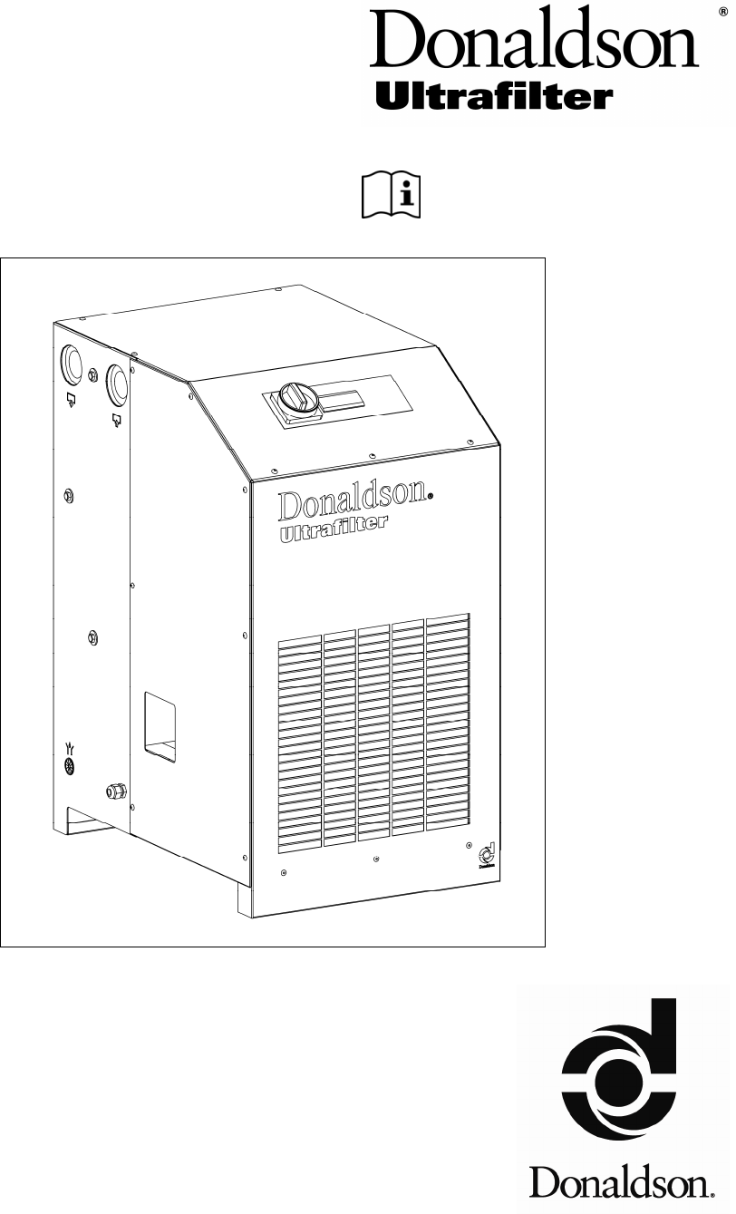
Operation Manual
Bedienungsanleitung • Manuel d’utilisation • Handleiding • Istruzioni per l’uso
• Manual de funcionamiento • Manual de Instruções • Driftsvejledning • Bruksanvisning
• Käyttöohjeet • Εγχειρίδιο λειτουργίας • Návod k obsluze • Kasutusjuhend
• Használati utasítás • Eksploatavimo instrukcija • Lietošanas instrukcija
• Instrukcja obsługi • Navodila za uporabo • Návod na obsluhu • Instrucţiuni de utilizare
• ръководство за обслужване • Kullanım Kılavuzu • Betjeningsveiledning
• Руководство по эксплуатации
Wall Bracket
Ultra-Filter DF 0035 — DF 1100
EN – Operating Instruction
O11100000009
12.2010
EN – Compressed Air-Dryer
BURAN
DC 0020 AB – DC 0850 AB
Type Code
12.2010 EN_2
Series BURAN
Type code Model Type no. Material no.
DC 0020 AB 1110 A 1CY1110000009
DC 0035 AB 1111 A 1CY1111000009
DC 0050 AB 1112 A 1CY1112000009
DC 0065 AB 1113 A 1CY1113000009
DC 0085 AB 1114 A 1CY1114000009
DC 0105 AB 1115 A 1CY1115000009
50-60 Hz
DC 0125 AB 1116 A 1CY1116000007
DC 0150 AB 1117 A 1CY1117000007
DC 0180 AB 1118 A 1CY1118000007
DC 0225 AB 1119 A 1CY1119000007
DC 0300 AB 1120 A 1CY1120000007
DC 0360 AB 1121 A 1CY1121000007
DC 0450 AB 1122 A 1CY1122000007
DC 0550 AB 1123 A 1CY1123000007
DC 0650 AB 1124 A 1CY1124000007
DC 0750 AB 1125 A 1CY1125000007
DC 0850 AB 1126 A 1CY1126000007
50 Hz
DC 0125 AB 1116 A 1CY1116000008
DC 0150 AB 1117 A 1CY1117000008
DC 0180 AB 1118 A 1CY1118000008
DC 0225 AB 1119 A 1CY1119000008
DC 0300 AB 1120 A 1CY1120000008
DC 0360 AB 1121 A 1CY1121000008
DC 0450 AB 1122 A 1CY1122000008
DC 0550 AB 1123 A 1CY1123000008
DC 0650 AB 1124 A 1CY1124000008
DC 0750 AB 1125 A 1CY1125000008
Version air-cooled
DC 0850 AB 1126 A 1CY1126000008
60 Hz
Original instruction are in ENGLISH!
Technical modifications are subject to change without notice; errors not excluded.
ultratroc gmbh
Drucklufttechnik
Postfach 2653 D-24916 Flensburg
Ochsenweg 73 D24941 Flensburg
Internet: http://www.donaldson.com
Table of contents
EN_3 12.2010
Page
Type code EN_2
Part 1 Important user information 1.1
General Notes EN_4
1.2
Legal requirements for the user EN_5
1.3
Safety regulations EN_6
1.4
Refrigerant handling EN_7
All safety notes in this operating instruction which may cause harm to personnel or
equipment, when ignored, are marked by the following symbols:
General danger symbol
Electrical danger symbol
1.5
First Aid EN_8
1.6
Disposal EN_8
Part 2 Installation 2.1
Transportation EN_9
2.2
Requirements on the place of installation EN_9
2.3
Installation (Mounting) EN_9
2.4
Compressed air connection EN_10
2.5
Electric Connection EN_10
2.6
Connection condensate drain EN_11
Part 3 Description 3.1
Designation EN_12
3.2
Intended use EN_12
3.3
Unit layout EN_12
3.4
Electronic regulator EN_12
3.5
Nominal power of CA-Dryer EN_13
3.6
Principle of operation EN_13
3.7
Mode of operation EN_13
3.8
Condensate draining EN_14
Part 4 Operation 4.1
Commissioning EN_15
4.2
Starting EN_15
4.3
Operation EN_15
4.4
Stopping EN_16
Part 5 Maintenance 5.1
Maintenance EN_17
5.2
Troubleshooting EN_18
5.3
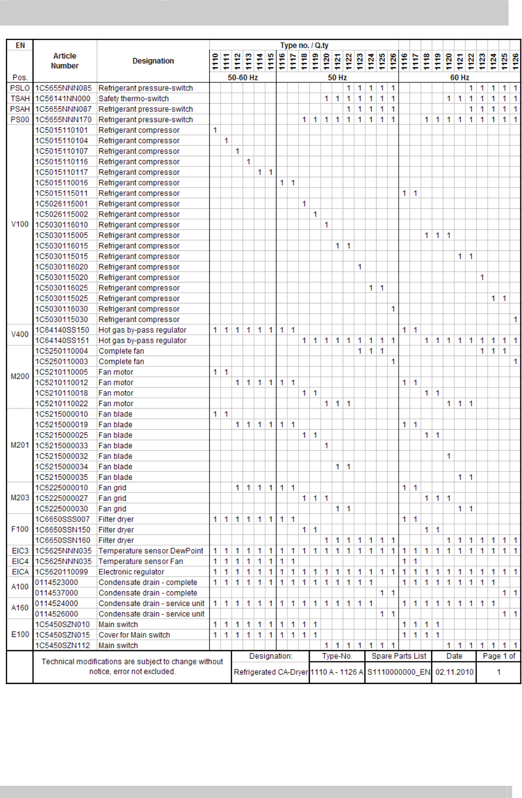
Spare parts list EN_24
Part 6 Technical data 6.1
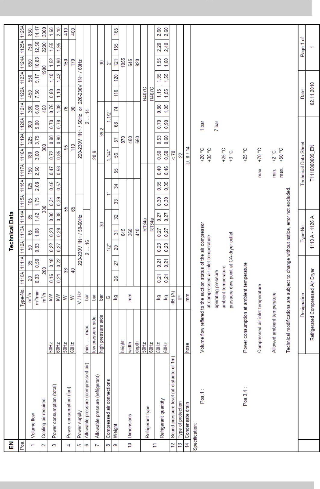
Technical data EN_25
Part 7 Appendix legend 7.1
Appendix legend EN_26
Appendix Apx 1 Units layout
Apx 2 Spare parts view
Apx 3 Wiring diagrams
Apx 4 PI diagram
Apx 5 Declaration EC-conformity

Part 1 Important User Information
12.2010 EN_4
1.1 General notes
•
This compressed air-dryer is called CA-dryer in the
following.
•
The Company does not accept responsibility if safety
regulations are not met during handling, operation,
maintenance and repair, even though these are not strictly
stated in these operating instructions.
•
We recommend the notice of these operating instructions
verified by the operating personnel in writing (personnel file).
•
We recommend translation of these operating instruction
into native language of foreign workers.
•
The usability and the life cycle of the compressed air-dryer
as well as the avoidance of premature repairs depends on
proper operation, maintenance, care and competent repair
under consideration of these operating instructions.
•
Hints to figures and locations are in brackets, e.g. (Fig.3/7).
•
Due to our position as suppliers of components we do not
always know the final usage and total range of products’
application. We constantly improve our products to the latest
state of science and technology and therefore, we assume
that our product are free from defects in sense of product
liability. However, it cannot be excluded that during faulty
operation in critical areas of application especially at danger
to life and limb of persons involved, additionally safety
measures may be necessary. Therefore, we request the
user of our components / units, to ensure in his own interest,
to inform us about the application of our products in order to
initiate additional safety measures, if necessary.
•
Keep this manual for future reference.

Important User Information
Part 1
EN_5 12.2010
1.2 Legal requirements for the user
1.2.1 Classification EC
regulation 97/23 • Due to classification into category 2 (types 1125A and
1126A) according to EC-Pressure Equipment directive,
the CA-Dryer are “systems to be monitored”.
1.2.2 Check of working
materials • Before starting the CA-Dryer, the user has to check the
working materials and record this accordingly.
1.2.3 Periodical checks • The user of the CA-Dryer has to find out the test periods
of the complete unit and the unit parts on base of a safety
related technical evaluation.
1.2.4 Instruction EN 378-1 • The user has to provide the instructions for the operators
as well as their information of the used working media. A
yearly instruction is mandatory.
1.2.5 Short Operating
Instruction EN 378-2 • A „Short Operating Instruction“ must be prepared by the
user and positioned next to the machine.
1.2.6 Documentation EN
378-4.3.1 EC regulation
842/2006
• The user is committed to create a unit record of the
refrigerating plant when using more than 3 Kg refrigerant.
A guideline can be provided by the service.
1.2.7 Maintenance EN 13 313 • Maintenance has to be provided by qualified personnel
only.

Part 1 Important User Information
12.2010 EN_6
1.3 Safety Regulations
Attention!
The operator has to observe the national working-, operating-
and safety regulations. Also existing internal factory regulations
must be met.
Maintenance and repair work must only be carried out by
specially trained personnel and, if necessary, under supervision
of a person qualified for this work.
• Protective or safety devices must not be removed, modified
or readjusted temporarily or permanently.
• User proper tools for maintenance and repair work only.
• Use original spare parts only.
Attention!
All maintenance and repair works must only be executed at
stopped machine, disconnected power supply and pulled mains
plug. Ensure that the CA-dryer cannot be switched on by
mistake.
• Prior to dismounting a part under pressure disconnect the
CA-dryer from all pressure sources and depressurize the CA-
dryer.
• Do not use inflammable solvents for cleanings.
• Keep the environment absolutely clean during maintenance
and repair works. Keep free of dirt by covering the parts and
free openings with clean cloth, paper or adhesive tape.
• Never weld at the pressure vessel or modify it in any way.
• Ensure that no tools, loose parts or similar are left in the
system.
• The casing of the CA-Dryer must not be stepped on.
• The CA-Dryer must not be used as deposit station.
• CA-Dryer must only be operated within the limits stated in the
nameplate.
• Condensate drain system access opening is intended to
manage the drain only (display visibility and test button) : a
deeper access inside the CA-Dryer may cause injuries due to
refrigerant hot piping.

Important User Information
Part 1
EN_7 12.2010
1.4 Refrigerant
handling
•
Wear eye protection and protective gloves.
•
Avoid contact of liquid refrigerants with your skin (frostbite).
•
Do not inhale refrigerant vapours.
•
To avoid higher concentrations, all work rooms must be
ventilated very well. The opening of windows and doors may
not be sufficient, so an exhausting system must be used
directly at the supply point or near the floor.
•
Do not smoke, because fire might decompose the
refrigerant. The resulting substances are toxic and must not
be inhaled.
•
Do not have refrigerants escaped during filling or repair
work. Cover with tape.
•
Leave the room immediately and only enter after the room
has been sufficiently ventilated when refrigerant
concentrations (e.g. pipe line leakages) appear suddenly.
•
Execute welding and soldering works on refrigerating
systems in well ventilated rooms only. Refrigerants will be
decomposed in flames as well as in electrical arcs.
•
The resulting decomposition products are toxic.
•
Before welding and soldering at refrigerating systems, the
refrigerant must be removed.
•
A stinking smell points to decomposition of refrigerant due to
overheating:
— leave room immediately;
— ventilate room very well.
1.4.1 Refrigerant
charging and
discharging
•
refrigerant charging and discharging operations shall be
made by qualified personnel only.
•
Do not throw out refrigerant in the environment during
discharge operation. Use proper refrigerant recovery
system.
•
In case of refrigerant charging requirement, use only
refrigerant type and quantity as indicated in the CA-Dryer
nameplate.
1.4.2 Refrigerant characteristics
Refrigerant Chemical formula TLV GWP
R134a – HFC CH
2
FCF
3
1000 ppm 1300
R407C – HFC R32/125/134a (23/25/52)
CHF
2
CF
3
/CH
2
F
2
/CH
2
FCF
3
1000 ppm 1653
Part 1 Important User Information
12.2010 EN_8
1.5 First aid
1.5.1 General notes:
•
Immediately bring casualty into the fresh air or into a well
ventilated room.
•
Assistants must pay attention to self-protection!
•
Take off contaminated clothes.
•
Never leave the casualty unattended!
•
CALL THE DOCTOR and inform him that accident has
been caused by refrigerants, as to be read on the name
plate!
1.5.2
After inhaling:
•
Bring casualty into the fresh air, keep him warm, and let him
relax.
•
At breathlessness: Oxygene therapie
•
At apnoea: Resuscitation
•
Mouth-to-nose resuscitation, mouth-to-mouth resuscitation
or with equipment.
•
Medical treatment necessary
1.5.3
After skin contact:
•
At skin contact, clean with water and soap immediately.
•
After contact with the fluid, undercooled skin areas must be
cooled with warm (not hot) water.
1.5.4
After eye contact:
•
Flush well opened eye with running water for at least 10
minutes.
•
Contact doctor.
1.5.5
Notes for the
doctor:
•
Inform doctor about the used refrigerant.
•
After inhalation, deep breathing of a corticoid emulsive
dosing aerosol (e.g. Ventolair) as soon as possible.
•
Prohobition of using adrenergic drugs.
•
Prophylactic pulmonary edema after inhalation of
decomposition products / fire gases
1.6 Disposal
•
When disposing of used devices, pay attention to oil and
refrigerant in the hermetical sealed refrigerating circuit of
CA-dryers. Therefore, before dismounting, these operation
media must be disposed by a special company.
•
The used materials are listed on the recycling label inside
the CA-dryer.
Attention!
Do not dispose waste oil into the environment. Do not mix with
household rubbish and do not burn it unauthorized plants.
• The escape of refrigerant into the atmosphere must be
prevented by appropriate measures.
Installation
Part 2
EN_9 12.2010
2.1 Transportation Transportation has to be carried out in the normal operating
position of the CA-dryer.
For a short time an inclined position of 45° is all owed.
Handle with care. Heavy blows could cause irreparable damage.
2.2 Requirements on
the place of
installation
At the site of installation, the CA-dryer can be installed without
anchorage or special foundation at the location desired.
The CA-dryer is provided for an ambient temperature of 25 °C.
Attention!
To avoid corrosion on components of the CA-dryer the
compressed and ambient air must be free of aggressive parts.
The CA-dryer are provided for inside mounting.
Deviating conditions require the consultation of the
manufacturer.
To prevent the condensate from freezing the room temperature
must not drop below +2 °C.
Attention!
At different ambient conditions pay attention to the layout data!
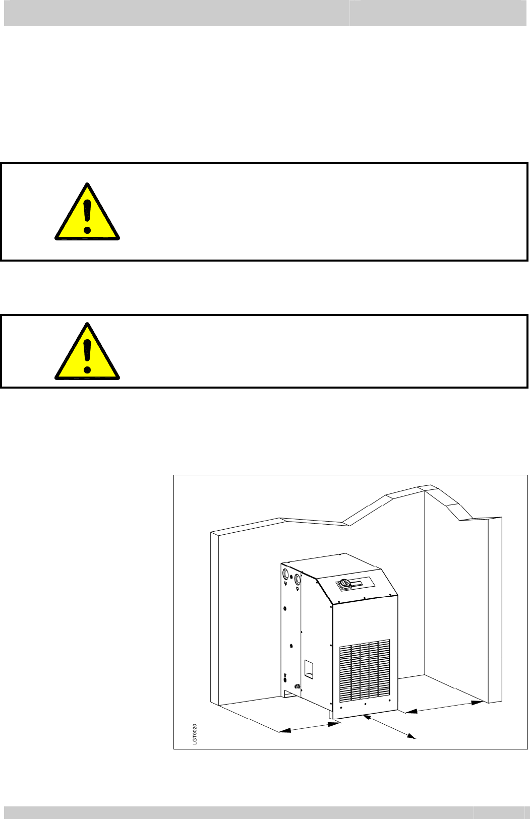
2.3 Installation
(mounting) The CA-dryer must be installed that accessibility to the front
panel is ensured. Furthermore leave space for service purposes
on both sides of the CA-dryer (fig.2.3a).
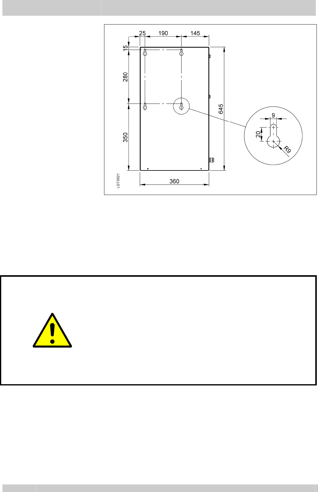
Wall mounting is possible with types 1110A-1116A (fig.2.3b).
Fig.
2.3a Installation of CA-dryer
Part 2 Installation
12.2010 EN_10
Fig.
2.3b Preparation wall
mounting
2.3.1 Version air cooled
The cooling air is sucked in by the refrigerant condenser (Apx
1/3) and discharged at the right side (Apx 1/4). Both areas must
be kept free and must non be obstructed.
2.4 Compressed air
connection
The connection must be executed acc. to marking at the CA-
dryer (Apx 1/1 + 1/2).
For service purposes the installation of a bypass line in
recommended (additional equipment).
Attention!
Before mounting the CA-dryer, welding residual, rust or other
pollution must be removed from the pipelines to be connected.
If pollution cannot be excluded, proper filter system must be
installed.
The compressed air pipes must be installed stress-free.
Expansion joints are recommended in case of vibrations and
pulsations.
CA-dryer must only be operated within the temperature and
pressure limits stated on the nameplate.
Prior to use, the user must fit safety / pressure relief devices on
the CA-system.
2.5 Electric connection The CA-dryers are completely equipped and wired. They
merely have to be connected to a power supply. The CA-dryer
are to be protected by slow-blow fuses as defined in the wiring
diagram.
Operating voltage: according to name plate data.
Installation
Part 2
EN_11 12.2010
2.6 Connection
condensate drain A hose already pre-mounted at the condensate drain leads the
condensate out of the CA-dryer (Apx 1/5). A connection by the
costumer has to be carried out corresponding to the local
conditions.
The CA-dryers separates water as well as oil from the
compressed air. The water/oil mixture must not be led into the
sewage. Water and oil must be separated by suitable
separators (additional equipment).
A minimum operating pressure of 2 bar is required for safe
operation.
Attention!
Route outflow so that persons or objects will not be struck by
condensate (condensate outlet at operating pressure)!
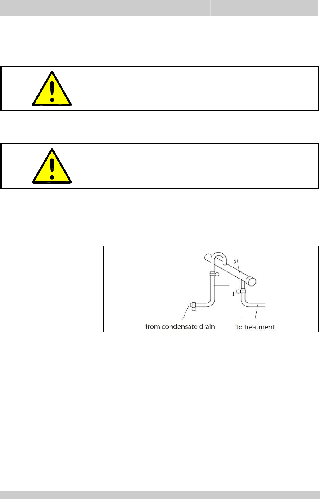
2.6.1 Connection
condensate
draining
The condensate drain pipe (fig.2.6/1) may be fixed to the wall
with a rising slope of maximum 5m. thereby the minimum
operating pressure increases for 0,1 bar per meter. The
collecting pipe (fig.2.6/2) has to have at least the cross-section
of the condensate outlet.
Fig.
2.6 Connection
condensate draining
Part 3 Description
12.2010 EN_12
3.1 Designation
Refrigerating compressed air-dryer (CA-dryer).
Version see type code (page 2).
3.2 Intended use Only compressed air will be dehumidified by the CA-dryer.
3.3 Unit Layout
See Appendix Apx 1 for CA-dryer components which are
accessible from outside.
Compressed air inlet
Compressed air outlet
Before maintenance works are to be executed at the CA-
dryer, the unit must be disconnected from the power
supply.
Risk of injury if the CA-dryer is not disconnected from the
power supply because of a freely rotating fan blade.
The refrigerant compressor of the refrigeration system
heats up during operation, so a risk of burn injuries is given
at maintenance works
3.3.1 Symbols
Condensate drain
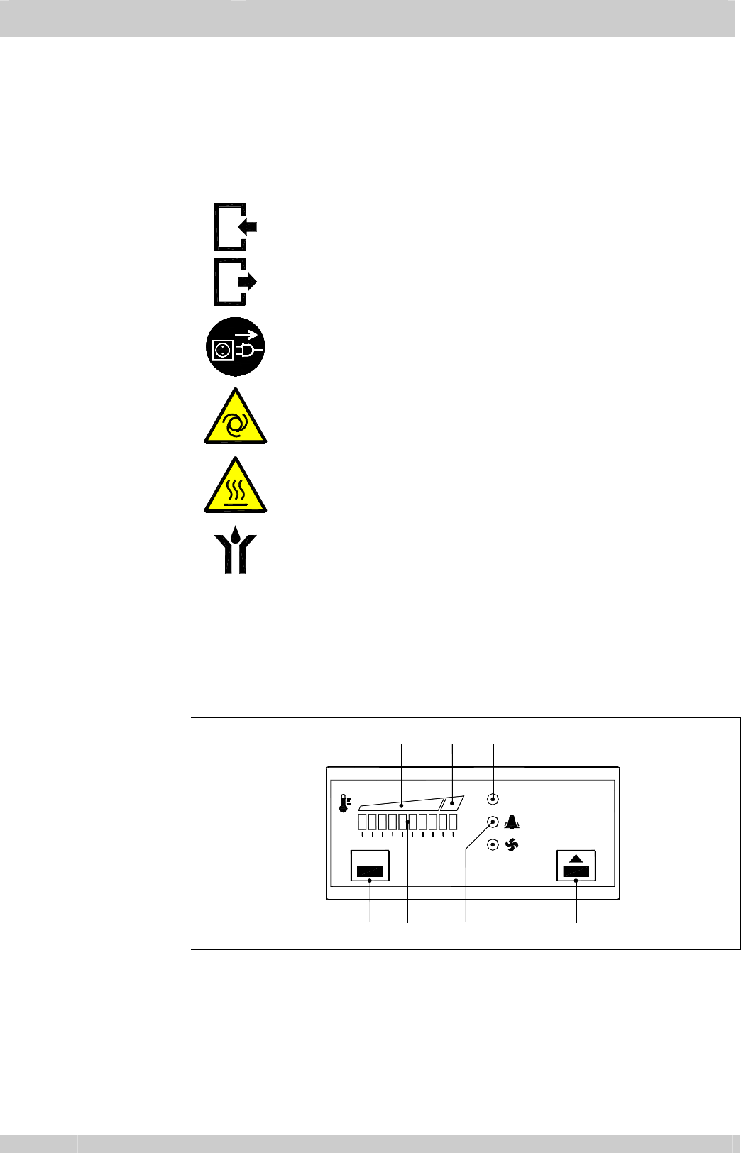
3.4 Electronic
regulator The electronic regulator DDS5 is a controller specially designed for
CA-dryers. It operates on the basis of the micro processors and
performs three functions:
— Pressure dew point display
— Pressure dew point alarm
— Refrigerant condenser fan control (1110A-1117A)
PQS0034_1
set
ON
7 1 8
56
4
3
2
1 10x Led green : Pressure dew point indication
2 Green area : Pressure dew point normal
3 Red area : Pressure dew point high
4 Led green : CA-dryer on
5 Led red : Alarm active (flashing)
6 Led yellow : refrigerant condenser fan on (1110A-1117A)
7 Set key
Fig.
3.4 Symbols
electronic
regulator
8 Up key

Description
Part 3
EN_13 12.2010
3.5 Nominal power of
CA-dryer
The nominal power of the CA-dryer mentioned in the technical
data is related to a working pressure of 7 bar, a compressed air
inlet temperature of 35 °C as well as an ambient te mperature of
25 °C acc. to ISO 7183.
Lower working pressure, higher compressed air inlet
temperature and/or higher ambient temperatures overload the
compressor which causes to an increased pressure dewpoint
and the compressor can be stopped by internal safety devices.
At essentially deviating operating conditions, contact the
deliverer of the CA-dryer for support.
3.6 Principle of
operation
The CA-dryer includes a refrigerant system cooling the
compressed air flow. The steam saturation limit is lowered
causing condensate to fall out, which is removed by the
condensate drain.
The higher the cooling temperature difference of the
compressed air, the higher the amount of condensate.
The lower the cooling temperature of compressed air, the lower
the moisture content.
The lower limit of the compressed air cooling results from the
working principle of the CA-dryer, which is based on the
moisture separation in liquid form.
3.7 Mode of operation
3.7.1 Compressed air
side The compressed air precooled in the Aftercooler and saturated
with moisture enters into the CA-dryer and is precooled in the
first cooling stage, the air-to-air heat exchanger without
additional energy. Cooling is carried out in counter flow to the
already cooled air heated during this process.
The cooling to the pressure dew point is performed in the
second cooling stage, the refrigerant-to-air heat exchanger
cooled by the refrigerant system installed. Subsequently, the
cooled compressed air is reheated in the air-to-air heat
exchanger as already described.
3.7.2 Refrigerant side The refrigerant is injected into the refrigerant-to-air heat
exchanger where it evaporates, thereby the compressed air is
cooled. The hot gas by-pass valve regulates the cooling
temperature and keeps the pressure dew point constant in
nearly all capacity stages. The refrigerant compressed by the
motor compressor is condensed within the condenser and is
available for the evaporation again.
3.7.3 Pressure dew point
control Any compressed air dryer can be operated under partial load
due to lower compressed air flow or lower compressed air inlet
temperature in the range of 0 to 100% load in permanent
operation.
Part 3 Description
12.2010 EN_14
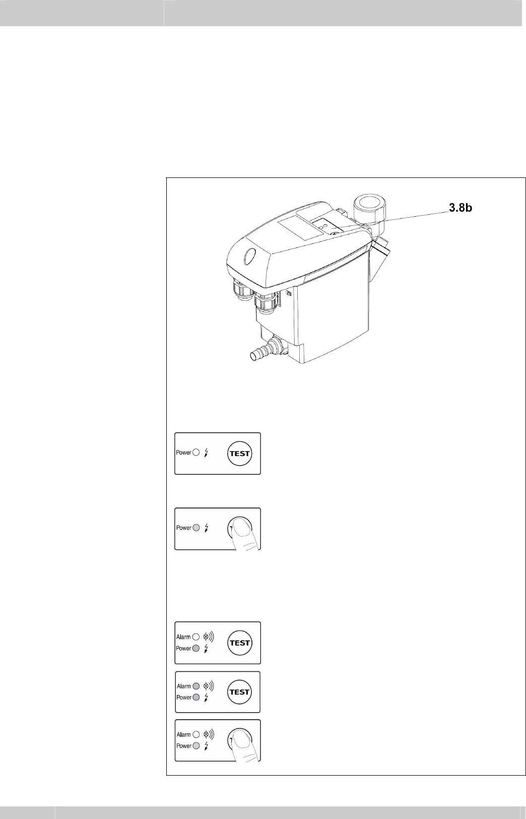
3.8 Condensate
draining The condensate drain (fig.3.8a) automatically drains the
condensate. A minimum pressure of 2 bar is required for safe
operation.
3.8.1 Condensate drain
sensor-controlled Once the container has filled with condensate, so that the
capacitive level sensor emits a signal, the internal solenoid valve
opens and the condensate is forced by the working pressure into
the discharge pipe.
The condensate drain electronic system ensures the closing of
the outlet opening before any compressed air can escape.
Fig.
3.8a Condensate drain
General
Fig.
3.8b Condensate drain
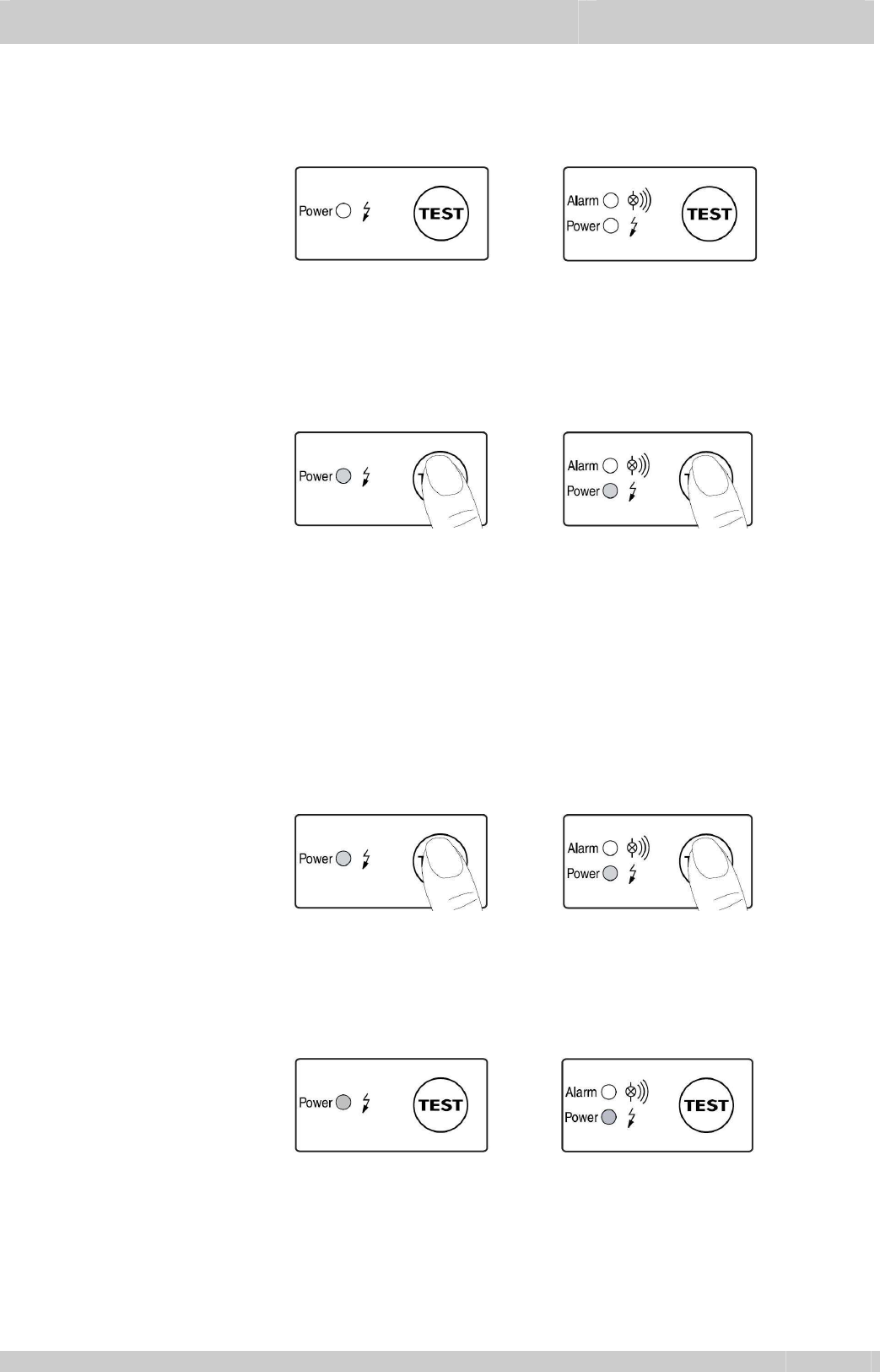
Operation panel Type 1110A-1124A
The power LED is lit up green when operating voltage is being
applied.
— Ready for operation. Power On
If the condensate discharge is not functioning
properly, the valve will keep opening (about
every 2 seconds) so as to clear the fault
automatically, if possible.
— Test valve function (manual drainage).
Press button for approx. 2 seconds. In
response to longer pressing, the valve will
keep opening. Do not use this function for
continuous draining!
Type 1125A-1126A
The operating states are indicated by two LED’s.
— Ready for operation. Power on.
— Malfunction / Alarm.
— Test of valve function and manual drainage:
briefly press button.
— Press button for >1 minute to test the alarm
function.

Operation
Part 4
EN_15 12.2010
4.1 Commissioning
After installation the CA-dryer is supplied with power via the
power cable or by operating the main switch (Apx 1/6).
Attention!
Before operating the operation switch (Apx 1/6), a waiting
period of at least 6 hours is absolutely necessary.
4.2 Starting
The CA-dryer is switched on via operation switch (Apx 1/6).
After approx. 5 minutes the compressed air admission is
possible by connecting the compressed air compressor.
The CA-dryer is designed for continuous operation and may
remain switched on during periods of no load, as it adapts to
the required performance automatically.
4.3 Operation Operation is indicated by the led “ON” of the electronic regulator
(fig.4.3/4)
The pressure dew point indication (fig.4.3/1) is showing the
pressure dew point reached by the CA-dryer.
PQS0034_1
set
ON
718
56
432
4.3.1 Electronic regulator
— Changing factory
setting
Fig.4.3
1. Press SET key (7) for 2 seconds to change from display into
setup mode.
2. First data is ALARM
ON
, shortly press SET key (7
data FAN
ON
, shortly press SET key (7) to return to data
ALARM
ON
.
3. In order to adjust actual data, keep pressed SET key (7) and
press UP key (8).
4. During the setup, led flashing will identify which data is
displayed :
— led ON (4) and ALARM (5) flashing = ALARM
ON
data
— led ON (4) and FAN (6) flashing = FAN
ON
data
5. Setup exit is automatic after 2 minutes or by pressing UP key (8).

Part 4 Operation
12.2010 EN_16
4.3.2 Electronic regulator
— Data range ALARM
ON
EIC3 temperature too high setpoint (ALARM
ON
) is
adjustable in the range +2 … 20 °C (factory setting 18°C),
resolution 2°K, hysteresis -2°K.
(ie : ALARM
ON
= 18°C; Alarm is active with EIC3 temperature
≥18°C for at least 5 minutes; Alarm condition resets
immediately with EIC3 temperature <16°C).
FAN
ON
EIC4 temperature fan setpoint (FAN
ON
) is adjustable in the
range +31 … 40 °C (factory setting 35°C), resolution 1 °K,
hysteresis -5°K.
(ie : FAN
ON
= 35°C; Fan start running with EIC4 temperature
≥35°C; Fan stop running with EIC4 temperature <30°C) .
4.4 Stopping At standstill periods, the CA-dryer is switched off with the
operation switch (Apx 1/6).
For longer standstill periods or service works, the CA-dryer
is switched off by pulling the power plug (Apx 1/8).
Maintenance
Part 5
EN_17 12.2010
5.1 Maintenance
Attention!
Prior to any maintenance works all safety regulations for
electrical systems and units must be observed (see also
part 1).
Maintenance intervals highly depend on the model of
operation and the ambient conditions on site, the intervals
below are only to be understood as general
recommendations.
5.1.1 Daily maintenance a) Check function of condensate drain.
Check, if water is drained.
Test valve function (manual drainage):
Press button for approx. 2 seconds.
In response to longer pressing, the valve will keep
opening.
Do not use this function for continuous draining!
b) Monitor pressure dew point (fig.3.4/1). In case of
differences to normal operation (see 5.2.2, 5.2.3).
c) Verify the refrigerant condenser for cleanliness.
5.1.2 Weekly
maintenance Inspection and cleaning of condensate draining system if
necessary.
5.1.3 Yearly maintenance Condensate drain: replace service unit.
For further information see separate instruction in the
service kit.
Leak tightness check : CA-Dryers mentioned in this manual
have refrigerant charge ≤30 kg (refrigerant quantity as
stated in the nameplate) : the maximum allowed leak rate of
2 % must not be exceeded.
5.1.4 Periodic checks at
pressure vessels CA-Dryers types 1125A and 1126A are included into the
pressure vessel guideline category II, fluid group 2 and have
a maximum pressure of 14 bar.
Periodic checks must be done according to National
legislations and the determinations of the user.
Attention!
Maintenance work must be performed at the depressurized
condensate drain only. For this purpose, the installation of a
bypass line is recommended.

Part 5 Maintenance
12.2010 EN_18
5.2 Trouble shooting
Symptom Cause ⇒
⇒⇒
⇒ Remedy
5.2.1 No Function 1. Check and ensure power supply if necessary.
2. If the power supply is ok, contact service or send CA-dryer
to the manufacturer.
5.2.2 Pressure dew point
too high 1. Temporary overload of the CA-dryer due to non-uniform
compressed air consumption ⇒
⇒⇒
⇒ check CA-dryer’s capacity
(see 3.4).
2. Ambient temperature too high or the room aeration is
insufficient ⇒
⇒⇒
⇒ reduce temperature and/or provide proper
ventilation.
3. CA-dryer volume flow too high ⇒
⇒⇒
⇒ reduce volume flow; ⇒
⇒⇒
⇒
check whether CA-dryer’s capacity is properly selected,
increase CA-dryer’s capacity.
4. EIC3 dew point sensor doesn’t detect the temperature
properly ⇒
⇒⇒
⇒ ensure the sensor is pushed into the bottom of
probe well or EIC3 dew point sensor need to be replaced.
5. Refrigerant condenser fan is never running ⇒
⇒⇒
⇒ see 5.2.6.
6. Refrigerant condenser is polluted ⇒
⇒⇒
⇒ clean condenser.
7. Hot gas by-pass valve is out of setting ⇒
⇒⇒
⇒ contact service.
8. Leak in the refrigerating fluid circuit ⇒
⇒⇒
⇒ contact service.
5.2.3 Pressure dew point
too low 1. Ambient temperature is too low ⇒
⇒⇒
⇒ restore normal condition.
2. (type 1110A-1117A) Refrigerant condenser fan is always on
and electronic regulator’s FAN led is flashing ⇒
⇒⇒
⇒ see
5.2.11.2.
3. (type 1118A-1126A) Refrigerant condenser fan is always on
⇒
⇒⇒
⇒ Fan control pressure switch SPV is defective ⇒
⇒⇒
⇒ contact
service.
4. Switch off CA-dryer and maintain compressed air flow. After
approx. half an hour, the pressure dew point will return to
normal value. Restart the unit. If the pressure dew point
decrease again contact service.
5.2.4 Water in
compressed air
system
1. Condensate drain is not drained sufficiently ⇒
⇒⇒
⇒ see 5.2.12.
2. CA-operating pressure too low ⇒
⇒⇒
⇒ increase operating
pressure; ⇒
⇒⇒
⇒ check whether CA-dryer’s capacity is properly
selected, increase CA-dryer’s capacity.
3. Temporary overload of the CA-dryer due to non-uniform
compressed air consumption ⇒
⇒⇒
⇒ check CA-dryer’s capacity
(see 3.4).
4. CA-dryer volume flow too high ⇒
⇒⇒
⇒ reduce volume flow; ⇒
⇒⇒
⇒
check whether CA-dryer’s capacity is properly selected,
increase CA-dryer’s capacity.
5. CA-inlet temperature too high ⇒
⇒⇒
⇒ restore normal conditions.
6. (Only with installed bypass line) Bypass valve is open ⇒
⇒⇒
⇒
close bypass valve.
7. (Only with installed bypass line) Bypass valve is leaking
⇒
⇒⇒
⇒ seal or replace bypass valve.

Maintenance
Part 5
EN_19 12.2010
5.2.5 Stopping CA-dryer
during operation 1. Compressor’s internal overload protection (klixon) is tripped
⇒
⇒⇒
⇒ eliminate cause of trouble (see 3.4) or contact service.
CA-dryer will restart automatically after compressor has
cooled down.
Note: the immediate restarting of the unit is not possible
because the compressor’s overload protection requires a
minimum time to cool down to an acceptable operating
temperature.
2. Compressor or starting device is defective ⇒
⇒⇒
⇒ contact
service.
3. CA-dryer volume flow too high ⇒
⇒⇒
⇒ reduce volume flow; ⇒
⇒⇒
⇒
check whether CA-dryer’s capacity is properly selected,
increase CA-dryer’s capacity.
4. CA-inlet temperature too high ⇒
⇒⇒
⇒ restore normal conditions.
5. Ambient temperature too high or the room aeration is
insufficient ⇒
⇒⇒
⇒ Reduce temperature or provide proper
ventilation.
6. Refrigerant condenser fan is never running ⇒
⇒⇒
⇒ see 5.2.6.
7. Refrigerant condenser is polluted ⇒
⇒⇒
⇒ clean condenser.
8. CA-operating pressure too low ⇒
⇒⇒
⇒ increase operating
pressure; ⇒
⇒⇒
⇒ check whether CA-dryer’s capacity is properly
selected, increase CA-dryer’s capacity.
9. (type 1120A-1126A) Safety thermo-switch FTS is tripped ⇒
⇒⇒
⇒
see 5.2.8.
10. (type 1122A-1126A) Safety high pressure-switch FPA is
tripped ⇒
⇒⇒
⇒ see 5.2.9.
11. (type 1122A-1126A) Safety low pressure-switch FPB is
tripped ⇒
⇒⇒
⇒ see 5.2.10.
5.2.6 Refrigerant
condenser fan is
never running
1. Check and ensure electric wiring.
2. Fan’s internal overload protection is tripped ⇒
⇒⇒
⇒ eliminate
cause of trouble (see 3.4) or contact service. Fan will restart
automatically after it has cooled down.
3. (type 1110A-1117A) Electronic regulator is defective ⇒
⇒⇒
⇒
contact service.
4. (type 1118A-1126A) Fan control pressure switch SPV is
defective ⇒
⇒⇒
⇒ contact service.
5. Leak in the refrigerating fluid circuit ⇒
⇒⇒
⇒ contact service.
5.2.7 High differential
pressure at CA-side 1. CA-dryer volume flow too high ⇒
⇒⇒
⇒ reduce volume flow; ⇒
⇒⇒
⇒
check whether CA-dryer’s capacity is properly selected,
increase CA-dryer’s capacity.
2. CA-operating pressure too low ⇒
⇒⇒
⇒ increase operating
pressure; ⇒
⇒⇒
⇒ check whether CA-dryer’s capacity is properly
selected, increase CA-dryer’s capacity.
3. Pressure dew point too low ⇒
⇒⇒
⇒ see 5.2.3.
4. Condensate drain is not drained sufficiently ⇒
⇒⇒
⇒ see 5.2.12.
5. Heat exchanger polluted ⇒
⇒⇒
⇒ contact service.
Part 5 Maintenance
12.2010 EN_20
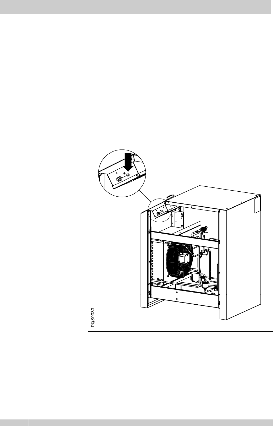
5.2.8 Safety thermo—switch
FTS is tripped
(type 1120A-1126A)
1. CA-dryer volume flow too high ⇒
⇒⇒
⇒ reduce volume flow; ⇒
⇒⇒
⇒
check whether CA-dryer’s capacity is properly selected,
increase CA-dryer’s capacity.
2. CA-inlet temperature too high ⇒
⇒⇒
⇒ restore normal conditions.
3. Ambient temperature too high or the room aeration is
insufficient ⇒
⇒⇒
⇒ reduce temperature and/or provide proper
ventilation.
4. Refrigerant condenser fan is never running ⇒
⇒⇒
⇒ see 5.2.6.
5. Refrigerant condenser is polluted ⇒
⇒⇒
⇒ clean condenser.
6. CA-operating pressure too low ⇒
⇒⇒
⇒ increase operating
pressure; ⇒
⇒⇒
⇒ check whether CA-dryer’s capacity is properly
selected, increase CA-dryer’s capacity.
7. Leak in the refrigerating fluid circuit ⇒
⇒⇒
⇒ contact service.
8. Safety thermo-switch FTS is defective ⇒
⇒⇒
⇒ contact service.
Note: Safety thermo-switch FTS require a reset : press
reset button (fig.5.2.8).
Fig.
5.2.8 Safety thermo-switch
FTS reset button
Maintenance
Part 5
EN_21 12.2010
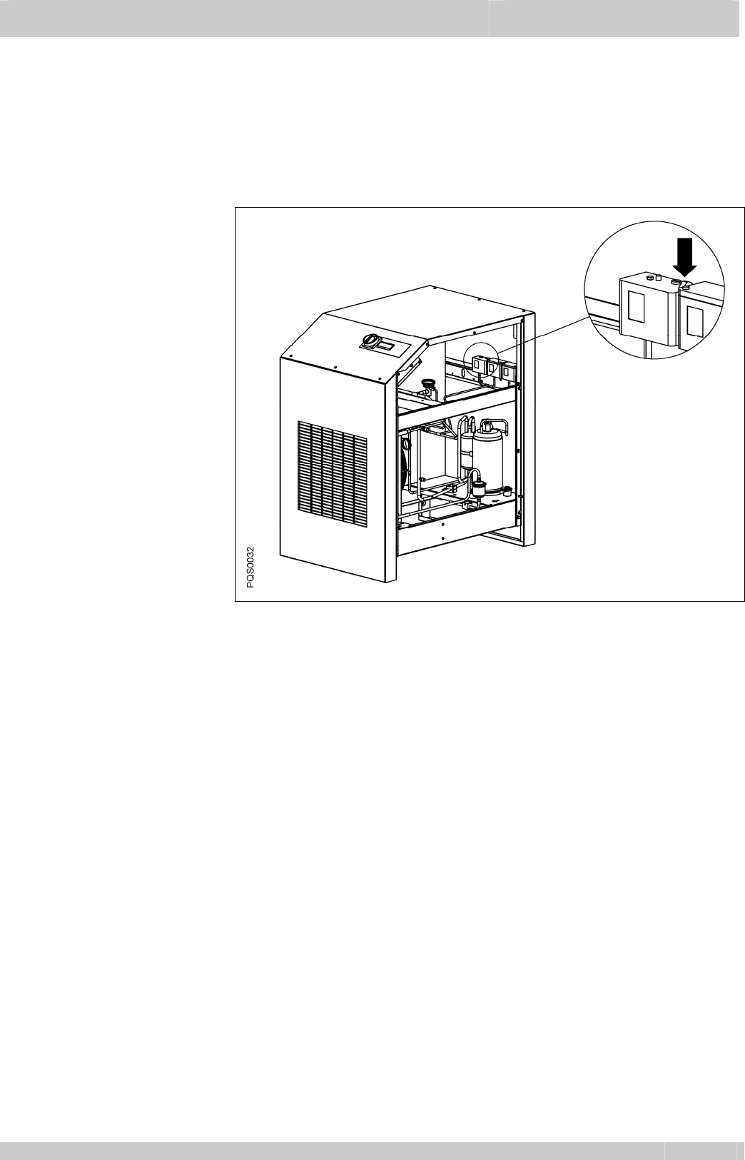
5.2.9 Safety high
pressure-switch
FPA is tripped
(type 1122A-1126A)
1. Ambient temperature too high or the room aeration is
insufficient ⇒
⇒⇒
⇒ reduce temperature and/or provide proper
ventilation.
2. Refrigerant condenser fan is never running ⇒
⇒⇒
⇒ see 5.2.6.
3. Refrigerant condenser is polluted ⇒
⇒⇒
⇒ clean condenser.
Note: Safety high pressure-switch FPA require a reset :
press reset button (fig.5.2.9).
Fig.
5.2.9 Safety high
pressure-switch FPA
reset button
5.2.10 Safety low
pressure-switch
FPB is tripped
(type 1122A-1126A)
Leak in the refrigerating fluid circuit ⇒
⇒⇒
⇒ contact service.
Part 5 Maintenance
12.2010 EN_22
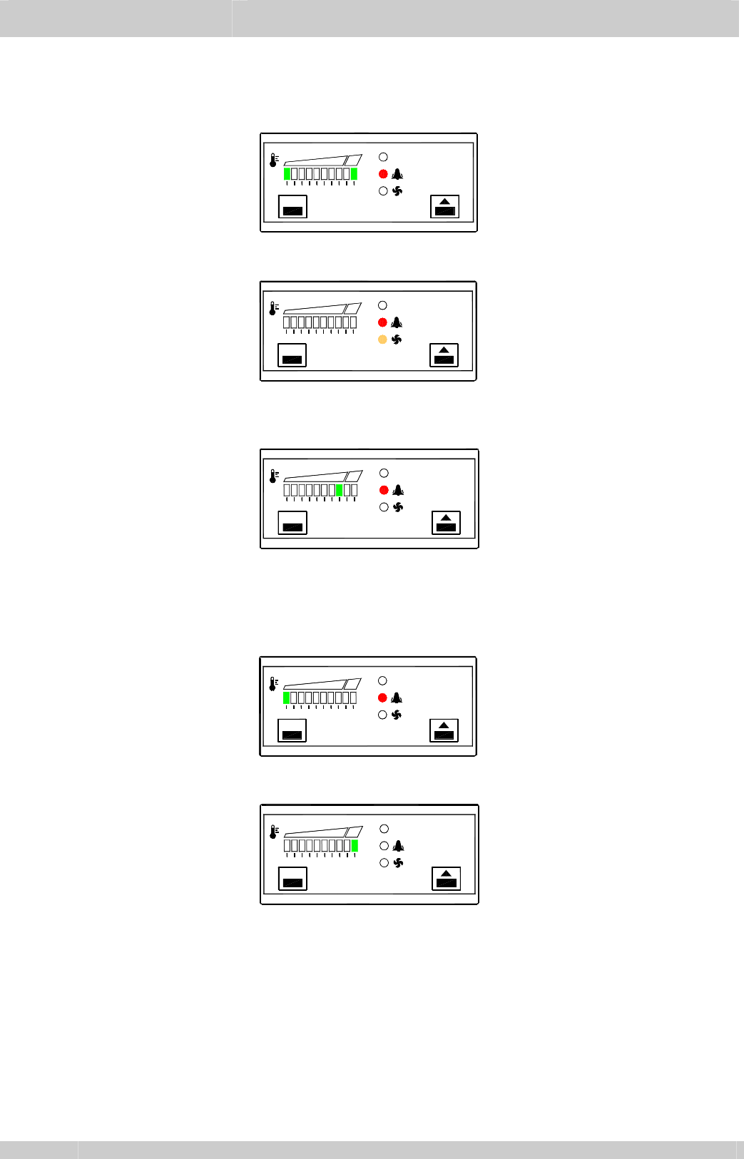
5.2.11 Electronic regulator DDS5
Symptom Cause ⇒
⇒⇒
⇒ Remedy
5.2.11.1
Alarm led and
display 1
st
(left)
and 10
th
(right) led
are flashing
PQS0034_2
set
ON
EIC3 dew point sensor is defective ⇒
⇒⇒
⇒ replace it.
5.2.11.2
Alarm led and Fan
led are flashing
(type 1110A-1117A)
PQS0034_3
set
ON
EIC4 fan control sensor is defective ⇒
⇒⇒
⇒ replace it.
Note: refrigerant condenser fan is always running.
5.2.11.3
Alarm led is
flashing and
display led is
lighted
PQS0034_4
set
ON
Pressure dew point alarm (higher than ALARM
ON
setpoint ⇒
⇒⇒
⇒
see 5.2.2 and 4.3.
Note: alarm become active 5 minutes later with dewpoint
temperature continuously higher than ALARM
ON
setpoint
5.2.11.4
Alarm led and
display 1
st
(left)
led are flashing
set
PQS0034_5
ON
Pressure dew point too low (lower than -1°C) ⇒
⇒⇒
⇒ see 5.2.3.
5.2.11.5
Display 10
th
(right)
led is flashing
set
PQS0034_6
ON
Pressure dew point too high (higher than 24°C) ⇒
⇒⇒
⇒ see 5.2.2.
Note: Alarm led could be lighted or not (alarm become active
5 minutes later with dewpoint temperature continuously
higher than ALARM
ON
setpoint)
Maintenance
Part 5
EN_23 12.2010
5.2.12 Condensate drain
Symptom Cause ⇒
⇒⇒
⇒ Remedy
5.2.12.1
LED not lighting
up
Power supply faulty.
Power supply board defective.
— Check voltage on type plate.
— Check connections.
— Check of the circuit boards for possible damage to be carried
out by qualified personnel only.
5.2.12.2
Pressing of test
button, but no
condensate
discharge
Feed and / or outlet line shut off or blocked.
Worn parts (seals, valve core, diaphragm).
Power supply board defective.
Service unit defective.
Dropping below necessary minimum pressure.
Maximum pressure exceeded.
— Check feed line and outlet line
— Check if valve opens audibly (press test button several times).
— Check of the circuit board for possible damage to be carried
out by qualified personnel only.
— Check operating pressure.
5.2.12.3
Condensate
discharge only
when test button
is being pressed
Feed line with insufficient slope; cross-section too small.
Excessive condensate quantities.
Service unit extremely dirty.
— Lay feed line with adequate slope
— Replace service unit.
5.2.12.4
Device keeps
blowing off air
Service unit defective or dirty.
— Replace service unit.
Part 5 Maintenance
12.2010 EN_24
Technical data
Part 6
EN_25 12.2010

Part 7 Legend Appendix
12.2010 EN_26
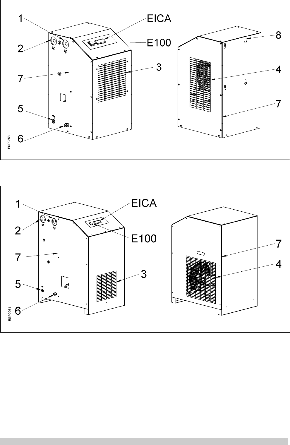
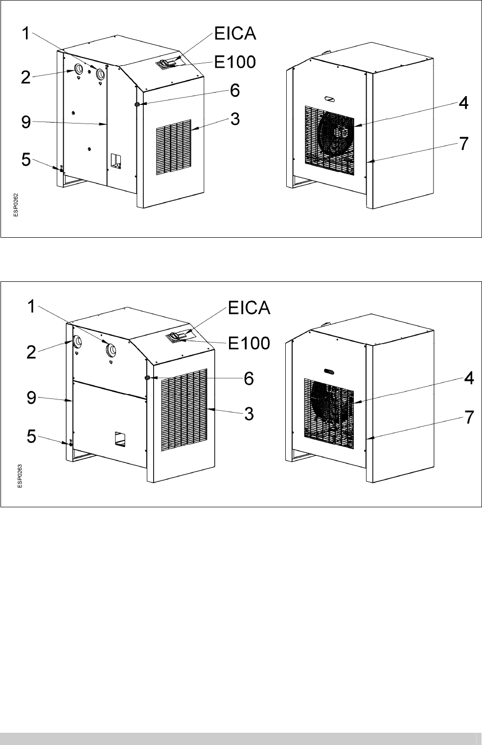
APX 1
1
2
3
4
5
Compressed air inlet
Compressed air outlet
Cooling air inlet
Cooling air outlet
Condensate drain
6
7
8
E100
EICA
Electric connection
Service access
Fixing holes
Operation switch
Electronic regulator
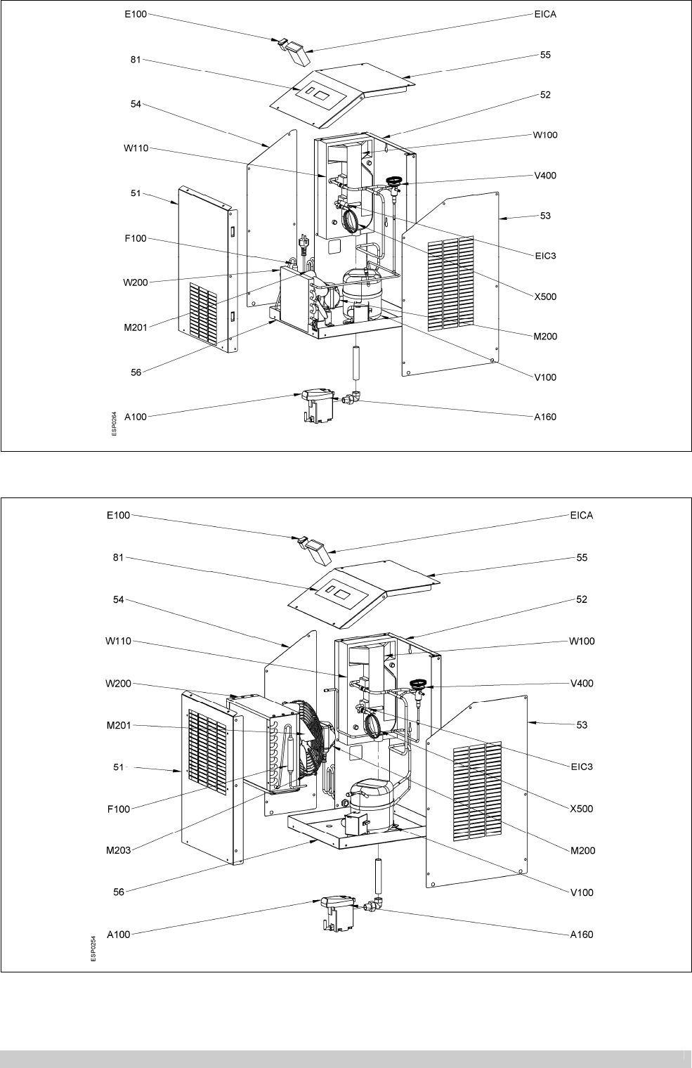
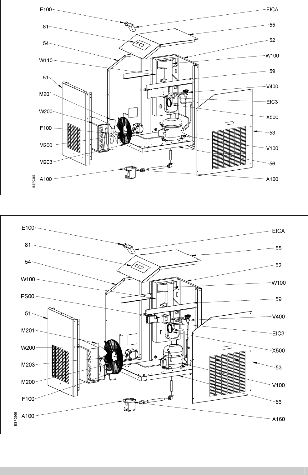
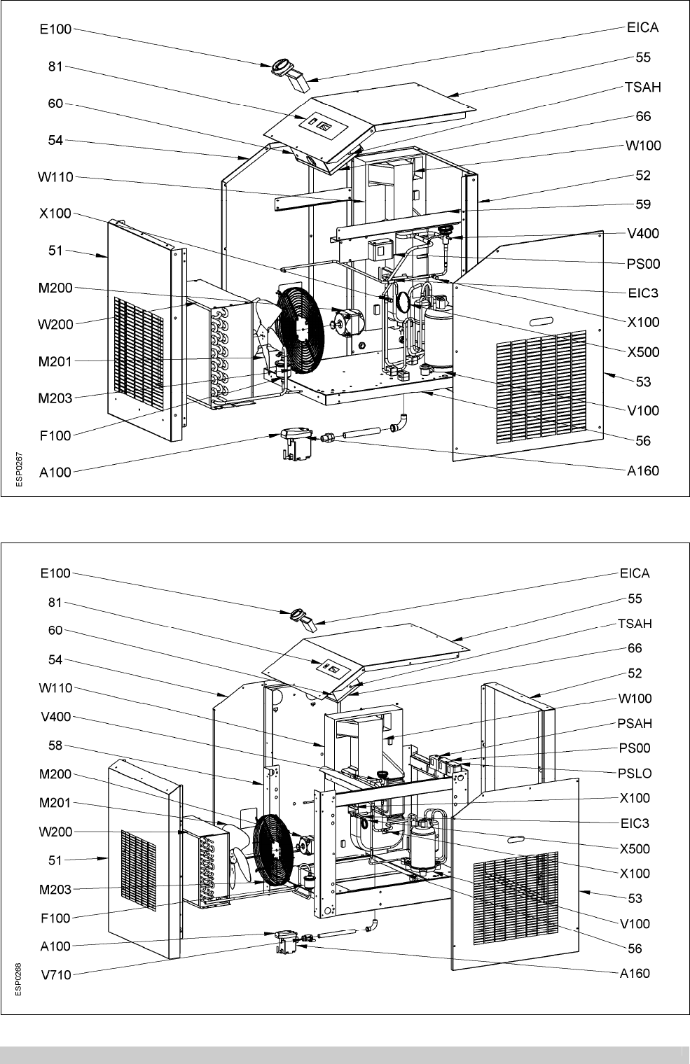
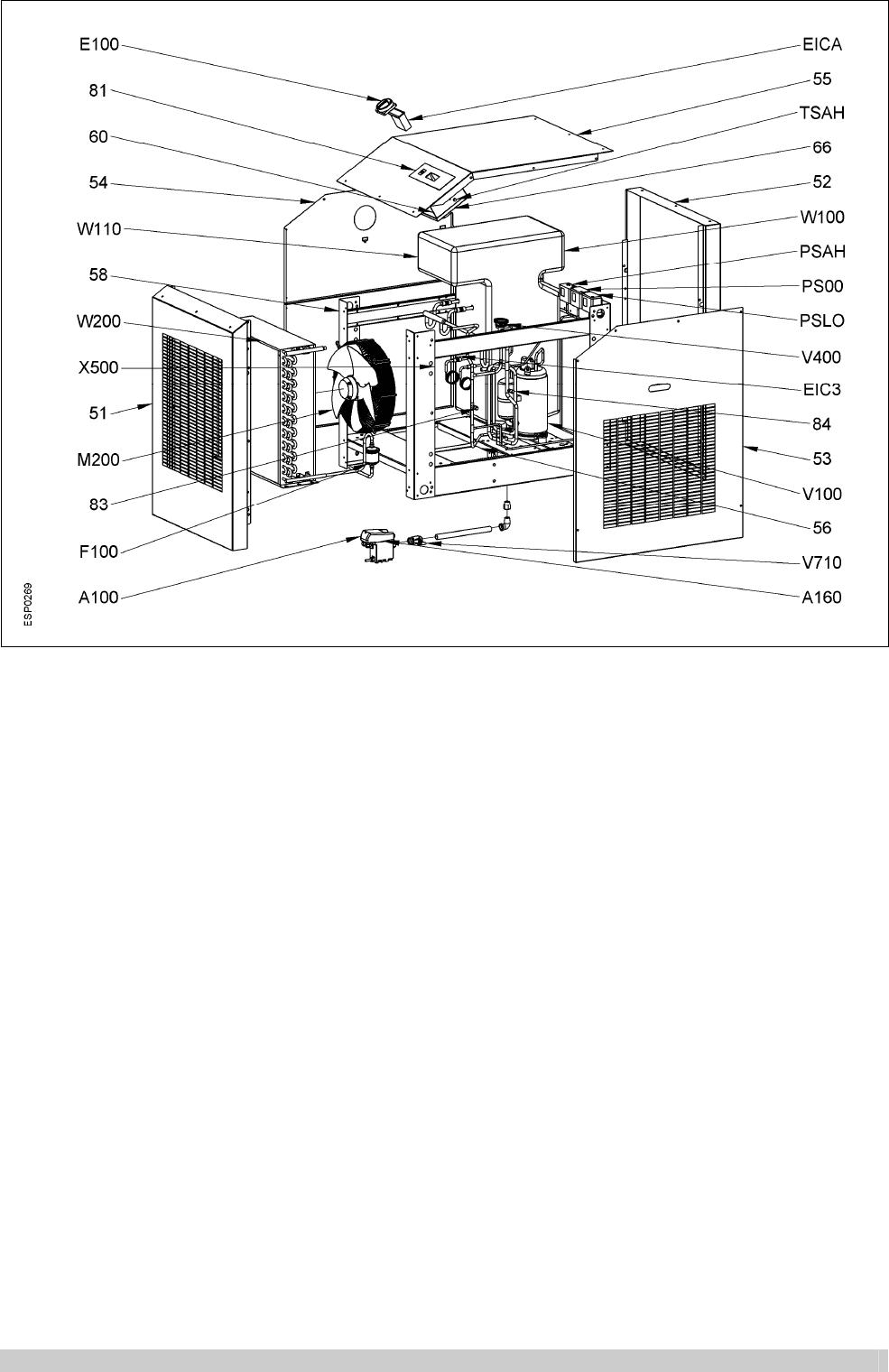
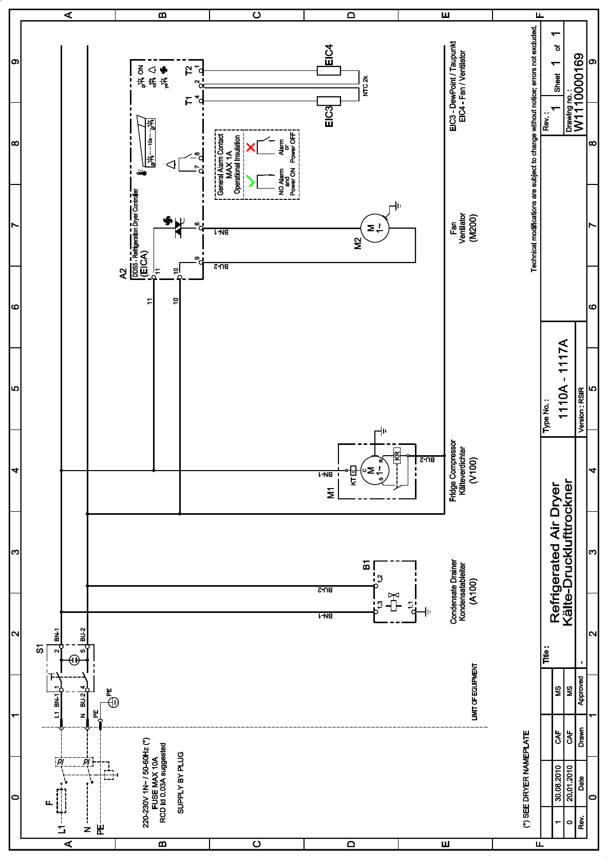
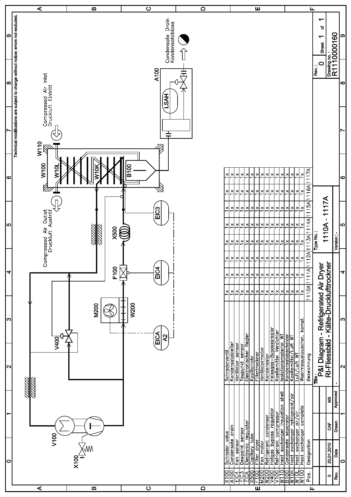
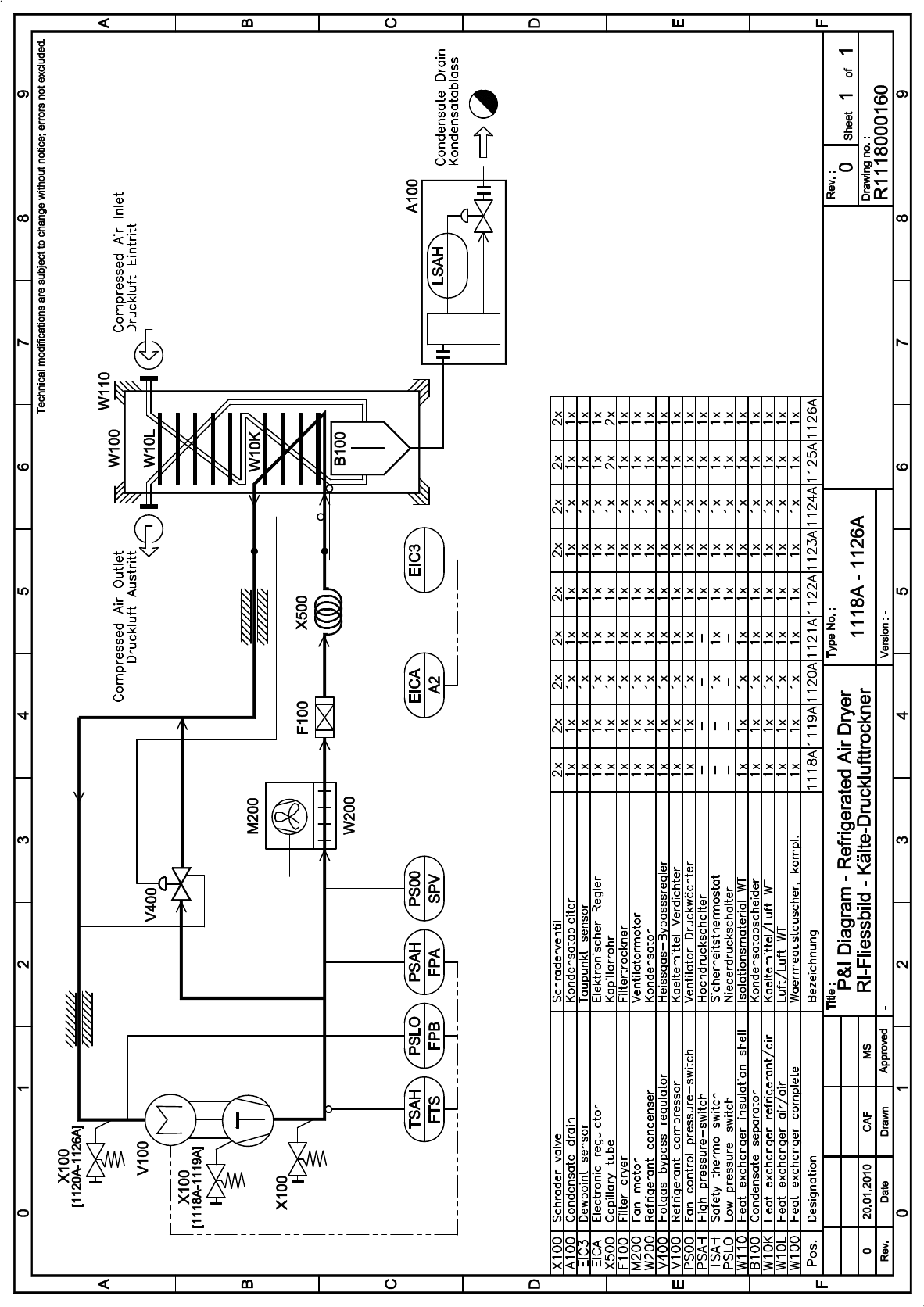
APX 2 &
APX 4
W100
W10L
W10K
B100
W110
PSLO
TSAH
PSAH
PS00
V100
V400
W200
M200
M201
M203
F100
X500
EIC3
Heat exchanger complete
Heat exchanger air/air
Heat exchanger refrigerant/air
Condensate separator
Heat exchanger insulation shell
Refrigerant low pressure-switch
Safety thermo-switch
Refrigerant high pres.-switch
Refrigerant pres.-switch Fan
Refrigerant compressor
Hot gas by-pass regulator
Refrigerant condenser
Fan (motor)
Fan blade
Fan grid
Filter drier
Capillary tube
DewPoint sensor
EIC4
V710
EICA
A100
E100
51
52
53
54
55
56
58
60
66
81
A160
X100
Fan sensor
Condensate drain service valve
Electronic regulator
Condensate drain – complete
Main switch
Front panel
Rear panel
Right lateral panel
Left lateral panel
Cover panel
Base plate
Support beam
Control panel
Cover control panel
Flow diagram sticker
Condensate drain – service unit
Schrader valve
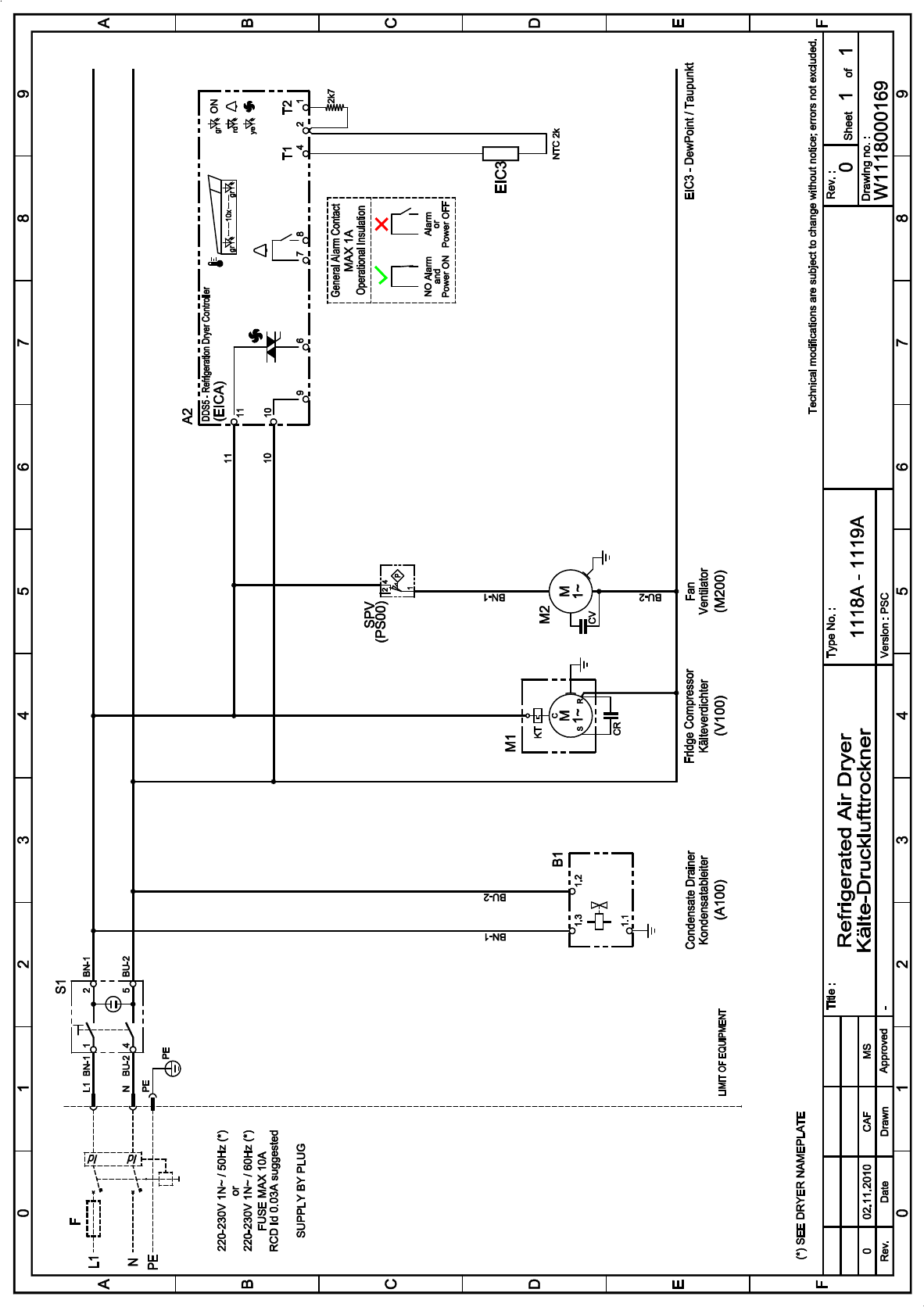
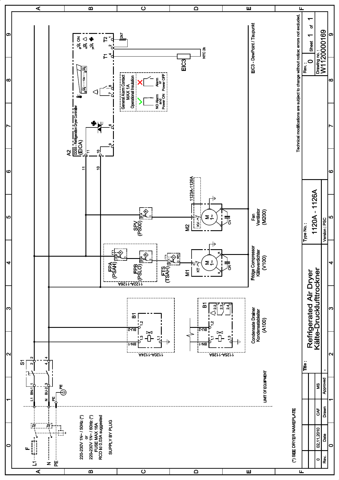
APX 3
S1
K
KT
KR
CS
CR
V
KV
CV
Main switch
Refrigerant compressor
Compressor thermal protection
Compressor starting relay
Compressor starting capacitor
Compressor run capacitor
Condenser fan
Fan thermal protection
Fan starting capacitor
PSLO
TSAH
PSAH
PS00
A2
EIC3
EIC4
B1
Refrigerant low pressure-switch
Safety thermo-switch
Refrigerant high pres.-switch
Refrigerant pres.-switch Fan
DDS Electronic regulator
DewPoint sensor
Fan sensor
Condensate drainer
12.2010
Apx 1.1 1110 A – 1116 A
Apx 1.2 1117 A – 1121 A
12.2010
Apx 1.3 1122 A – 1124 A
Apx 1.4 1125 A – 1126 A
12.2010
Apx 2.1 1110 A – 1111 A
Apx 2.2 1112 A – 1116 A
12.2010
Apx 2.3 1117 A
Apx 2.4 1118 A – 1119 A
12.2010
Apx 2.5 1120 A – 1121 A
Apx 2.6 1122 A – 1124 A
12.2010
Apx 2.7 1125 A – 1126 A
EG-Konformitätserklärung
EC declaration of conformity
Déclaration “CE” de conformité
EG-verklaring van overeenstemming
EU-konformitetsforklaring
DNN002003 Rev.01
DE — EN — FR
NL — DA
Hiermit enklären wir, dass die: Kälte-Drucklufttrockner
Herewith we declare that: Compressed air refrigeration dryer
Par la présente, nous déclarons, que la type de: Sécheur par réfrigération
Hiermde verklaren wij, dat de handel gebrachte machine: Perslucht koeldrogers
Hermed erklæres at produkttypen: Trykluft-køletørrer
Baureihe / Series / Série / Serie Typ / Type Artikel-Nr.:/Serial-No.:/ 97/23/EG – Kat. / Cat.
No Série/Serienummer:
DC 0020 AB 1110A 1C Y 1110 0 00 00 9 Art. 3 (3)
DC 0035 AB 1111A 1C Y 1111 0 00 00 9 Art. 3 (3)
DC 0050 AB 1112A 1C Y 1112 0 00 00 9 Art. 3 (3)
DC 0065 AB 1113A 1C Y 1113 0 00 00 9 Art. 3 (3)
DC 0085 AB 1114A 1C Y 1114 0 00 00 9 Art. 3 (3)
DC 0105 AB 1115A 1C Y 1115 0 00 00 9 Art. 3 (3)
DC 0125 AB 1116A 1C Y 1116 0 00 00 7 Art. 3 (3)
DC 0150 AB 1117A 1C Y 1117 0 00 00 7 Art. 3 (3)
DC 0180 AB 1118A 1C Y 1118 0 00 00 7 Art. 3 (3)
DC 0225 AB 1119A 1C Y 1119 0 00 00 7 Art. 3 (3)
DC 0300 AB 1120A 1C Y 1120 0 00 00 7 I
DC 0360 AB 1121A 1C Y 1121 0 00 00 7 I
DC 0450 AB 1122A 1C Y 1122 0 00 00 7 I
DC 0550 AB 1123A 1C Y 1123 0 00 00 7 I
DC 0650 AB 1124A 1C Y 1124 0 00 00 7 I
DC 0750 AB 1125A 1C Y 1125 0 00 00 7 II
DC 0850 AB 1126A 1C Y 1126 0 00 00 7 II
DC 0125 AB 1116A 1C Y 1116 0 00 00 8 Art. 3 (3)
DC 0150 AB 1117A 1C Y 1117 0 00 00 8 Art. 3 (3)
DC 0180 AB 1118A 1C Y 1118 0 00 00 8 Art. 3 (3)
DC 0225 AB 1119A 1C Y 1119 0 00 00 8 Art. 3 (3)
DC 0300 AB 1120A 1C Y 1120 0 00 00 8 I
DC 0360 AB 1121A 1C Y 1121 0 00 00 8 I
DC 0450 AB 1122A 1C Y 1122 0 00 00 8 I
DC 0550 AB 1123A 1C Y 1123 0 00 00 8 I
DC 0650 AB 1124A 1C Y 1124 0 00 00 8 I
DC 0750 AB 1125A 1C Y 1125 0 00 00 8 II
DC 0850 AB 1126A 1C Y 1126 0 00 00 8 II
folgenden weiteren Richtlinien entspricht: 97/23/EG
conform with the following directives: 2004/108/EG
correspond aux disposition suivantes: 2006/95/EG
komt overeen met de volgende verdere richtlijnen: 2006/42/EG
videre retningslinier som anvendtes:
Angewendete harmonisierte Normen, insbesondere: ASME VIII Div.1 ; EN378-2 ; EN953 ;
Applied harmonized standards in particular: EN954-1 ; EN1050 EN1088 ;
Normes harmonisée utilisées, notamment: EN10028-3 ; EN12100-1 ;
Gebruike geharmoniseerde normen, in het bijzonder: EN12100-2 ; EN12451 ; EN50081-2 ;
Harmoniserade normen som anvendtes, i særdeleshed: EN50082-2 ; EN60204-1
Referenz Qualität Dokument: Fd – DNN002002 Rev.01
Reference quality document:
Référence Document de qualité:
Referentie kwaliteit document:
Reference kvalitet dokument:
Flensburg, 02.11.2010
Datum / Date / Datum / Dato Underschrift / Signature / Handtekening / Underskrift
(Bevollmächtigter / Authorized person / Fondé de pouvoir / Gevolmagtiegde / Fuldmægtig)
ultratroc gmbh Drucklufttechnik
Ochsenweg 73, D-24941 Flensburg

u ultratroc gmbh Drucklufttechnik Tel. +49 (0) 4 61/9 49-0
Industrial Filtration Solutions Fax +49 (0) 4 61/9 49-3 69
Ochsenweg 73 www.donaldson.com
D-24941 Flensburg
Deutschland
Registergericht Flensburg HRB 30 Zahlungen bitte zugunsten Konto-Nr. 24 000 218
Geschäftsführer: Tod Carpenter Donaldson Filtration Deutschland GmbH BLZ 500 210 00
Werner Siring ING Bank Frankfurt IBAN: DE09500210000024000218
BIC: INGBDEFF
Zusätzliche Bedienungsanleitung in anderer Sprache
Additional manual in a different language
Sehr geehrter Kunde,
wenn Sie eine zusätzliche Bedienungsanleitung in einer anderen
Sprache wünschen senden Sie bitte Ihre Anforderung unter Angabe
der Modell — und Typenbezeichnung (siehe Typenschild), sowie Ihrer
kompletten Anschrift inklusive Emailadresse an:
ultratroc@donaldson.com
Mit freundlichen Grüssen
Ihr ultratroc Team
Dear customer,
Please send your demand with model name and type number
(mentioned on the name plate) and your complete address inclusive
email address, if you need an additional manual in a different
language to:
ultratroc@donaldson.com
Best Regards,
your ultratroc team
I:PL ManagementBuran 2010Buran I to IIIDocumentationDifferent language.doc
ХОЛОДНОЙ РЕГЕНЕРАЦИИ
![]() Германия
Германия

Адсорбционные осушители Donaldson позволяют получать сжатый воздух, влажность которого варьируется от 0,88 г/м3 до 0,0033 г/м3 (температура точки росы от минус 200С до минус 700С). Пропускная способность составляет от 5 до 8750 м3/час, максимальное рабочее давление 16 атм.
Адсорбционные осушители Donaldson делятся на два семейства: с холодной регенерацией и с горячей регенерацией.
Этот тип осушителей имеет отличия по температуре точки росы по сжатому воздуху:
Серия HED минус 20оС (содержание влаги в сжатом воздухе, после осушителя — 0,88 г/м3);
Серия ALD минус 40оС (содержание влаги в сжатом воздухе, после осушителя — 0,117 г/м3);
Серия MSD минус 70оС (содержание влаги в сжатом воздухе, после осушителя — 0,0033 г/м3).
Каждый осушитель имеет встроенный входной и выходной фильтр.
Производительность: от 5 м3/час до 1000 м3/час (при рабочем давлении 7бар)
Вариантное исполнение: Электронная система контроля и управления точкой росы Ultraconomy
Электроподключение: 230В / 1-фазн. / 50 Гц
Максимальное рабочее давление: 16 бар
| Модель серии HED, ALD и MSD |
Произво- дительность, м3/час |
Потери на регенерацию, м3/час | Габаритные размеры, Д х Ш х В, мм |
Подсоединение BSP |
||
| HED | ALD | MSD | ||||
| 0005 | 5 | 0,7 | 0,8 | 1 | 470х340х700 | G3/8′ |
| 0010 | 10 | 1,4 | 1,5 | 2 | 470х340х700 | G3/8′ |
| 0015 | 15 | 2,1 | 2,3 | 3 | 470х340х1060 | G3/8′ |
| 0025 | 25 | 3,5 | 3,8 | 4 | 470х340х1060 | G1/2′ |
| 0035 | 35 | 4,9 | 5,3 | 7 | 470х340х1060 | G1/2′ |
| 0050 | 50 | 7,0 | 7,5 | 10 | 670х460х1610 | G3/4′ |
| 0080 | 80 | 11,2 | 12 | 16 | 670х460х1610 | G3/4′ |
| 0100 | 100 | 14,0 | 15 | 20 | 670х460х1610 | G1′ |
| 0150 | 150 | 21 | 23 | 30 | 770х680х1980 | G1′ |
| 0175 | 175 | 24,5 | 26,3 | 35 | 770х680х1980 | G1′ |
| 0225 | 225 | 31,5 | 34 | 45 | 770х680х1980 | G1-1/2′ |
| 0300 | 300 | 42 | 45 | 60 | 770х680х1980 | G1-1/2′ |
| 0375 | 375 | 52,5 | 56 | 75 | 950х770х2190 | G1-1/2′ |
| 0550 | 550 | 77 | 83 | 110 | 950х770х2190 | G2′ |
| 0650 | 650 | 91 | 98 | 130 | 950х770х2190 | G2′ |
| 0850 | 850 | 119 | 128 | 170 | 1100х880х2350 | G2′ |
| 1000 | 1000 | 140 | 150 | 200 | 1100х880х2350 | G2′ |
Особенностью осушителей Donaldson серии Ultrapac Classic явлется закрытое (модульное) исполнение в комплекте с предварительным фильтром, фильтром тонкой очистки и автоматическим конденсатоотводчиком является недорогим решением для получения качественного воздуха с глубокой степенью осушения.
Опция:
Постоянный контроль точки росы на выходе осушителя, новейшая система контроля Ultraconomy, определяет количество поступающей на входе влаги и оптимально подстраивает время, когда осушитель
должен переключиться в режим регенерации, при обеспечении постоянной точки росы.
ГОРЯЧЕЙ РЕГЕНЕРАЦИИ

Серия HRE, для охлаждения адсобента часть потока осушенного воздуха расширяется до атмосферного и поступает на адсорбент. После охлаждения на колонну подаётся давление и колонна, которая находилась на регенерации, начинает работать в фазе адсорбции, а вторая колонна, наоборот, начинает регенерироваться. Средние потери на регенерацию оставляют не более 2%.
Серия HRG, для охлаждения адсорбента, воздух берётся из атмосферы при отключенном электронагревателе и поступает в колонну сверху вниз, совпадая с направлением потока осушённого воздуха. Потери сжатого воздуха отсутствуют.
Серия HRS, для охлаждения адсорбента, воздух берётся из атмосферы при отключенном электронагревателе и поступает в колонну снизу ввверхпротив направления потока осушенного воздуха. Потери сжатого воздухаотсутствуют.
Производительность: от 375 м3/час до 13 600 м3/час (при рабочем давлении 7бар)
Вариантное исполнение: Электронная система контроля и управления точкой росы Ultraconomy; паровой или водяной теплообменник
Электроподключение: 380В / 3-фазн. / 50 Гц
Максимальное рабочее давление: 16 бар
| Модель серии HRE, HRG и HRS |
Произво- дительность, м3/час |
Потери на регенерацию, м3/час |
Потребляемая мощноть, кВт |
Габаритные размеры, Д х Ш х В, мм |
Подсоединение BSP |
||
| HRE | HRG HRS | HRG | HRE HRS | ||||
| 0375 | 375 | 7,5 | 0 | 10,5 | 7,5 | 1430х800х2120 | DN 50 |
| 0550 | 550 | 11 | 0 | 11,2 | 11,2 | 1510х985х2340 | DN 50 |
| 0650 | 650 | 13 | 0 | 11,2 | 11,2 | 1530х1000х2300 | DN 50 |
| 0850 | 850 | 17 | 0 | 15,0 | 15,0 | 1590х1060х2370 | DN 50 |
| 1000 | 1000 | 20 | 0 | 19,0 | 15,0 | 1660х1120х2460 | DN 80 |
| 1350 | 1350 | 27 | 0 | 20,0 | 20,0 | 1850х1190х2580 | DN 80 |
| 1650 | 1650 | 33 | 0 | 28,0 | 24,0 | 1850х1340х2660 | DN 80 |
| 1950 | 1950 | 39 | 0 | 38,0 | 32,5 | 2040х1400х2720 | DN 100 |
| 2250 | 2250 | 45 | 0 | 38,0 | 32,5 | 2110х1410х2740 | DN 100 |
| 2750 | 2750 | 55 | 0 | 42,5 | 38,5 | 2260х1460х2790 | DN 100 |
| 3500 | 3500 | 70 | 0 | 52,5 | 44,5 | 3380х1890х3060 | DN 100 |
| 4000 | 4000 | 80 | 0 | 67,5 | 52,5 | 3490х1860х3180 | DN 150 |
| 5000 | 5000 | 100 | 0 | 86,0 | 71,0 | 3750х1950х3310 | DN 150 |
| 6000 | 6000 | 120 | 0 | 86,0 | 86,0 | 3880х2170х3460 | DN 150 |
| 7000 | 7000 | 140 | 0 | 111,0 | 95,0 | 4240х2270х3530 | DN 150 |
| 8750 | 8750 | 175 | 0 | 125,0 | 115,0 | 4570х2440х3570 | DN 200 |
| 10500 | 10500 | 210 | 0 | 153,0 | 135,0 | 4780х2600х3310 | DN 200 |
| 11500 | 11500 | 230 | 0 | 174,0 | 153,0 | 4970x2750x3350 | DN 200 |
| 13600 | 13600 | 272 | 0 | 196,5 | 177,5 | 5280x2975x3380 | DN 200 |

Осушители серии HRE / HRG / HRS — осушители с горячей регенерацией адсорбента. Для регенерации окружающий воздух с помощью воздуходувки, создающей небольшое избыточное давление, подаётся на электронагреватель, а затем пропускается через осушаемый адсорбент для регенерации и выбрасывается в атмосферу. Для снижения затрат на электроэнергию, электронагреватель может быть заменён или дополнен паровым или водяным теплообменником, или использовать горячий воздух с последней ступени сжатия турбокомпрессора.
Экономичное решение для глубокой осушки воздуха. Адсорбционные осушители с горячей регенерацией адсорбента позволяют значительно уменьшить или полностью исключить потери сжатого воздуха на регенерацию. Законченная система с внешним источником тепла для регенерации работает в непрерывном полностью втоматическом режиме. Система с тепловой регенерацией состоит из двух параллельно соединенных емкостей, работающих попеременно в режимах адсорбции и регенерации. Высокоэффективные осушители с горячей регенерацией работают в диапазоне от 375 до 13600 нм3/ч , производя воздух высокого качества и требуемой точки росы. Применение метода тепловой регенерации вместе с длительным циклом адсорбции позволяет полностью спользовать поглотительную емкость адсорбента.
Принцип работы:
Сжатый воздух поступает в на вход осушителя через поворотный кран и газовый диффузор, затем подается в адсорбционную колонну для дальнейшего осушения, при котором достигается требуемая точка росы. После этого осушенный воздух через обратный клапан и выход осушителя поступает в пневмосеть для дальнейшего использования. Пока одна колонна осуществляет процесс адсорбции, другая находится на регенерации. Для регенерации давление в колонне снижается до атмосферного посредством открытия клапана. Через воздуходувку нагнетается атмосферный воздух, который затем проходит через электронагреватель и подается на адсорбент для регенерации.
Регенерирующий воздух затем выбрасывается из системы через поворотный кран и выход для регенерирующего воздуха. Для охлаждения поток атмосферного воздуха подается при выключенном нагревателе. Воздух проходит сверху вниз вдоль адсорбента, а затем через поворотный кран выбрасывается в атмосферу. После охлаждения поворотный клапан, стоящий на выходе регенерирующего потока, закрывается и колонна встает в режим stand-by.
При срабатывании таймера (через 6 часов после начала регенерации) клапаны осушителя пневматически переключаются, и процесс адсорбции начинает происходить в регенерированной колонне, а вторая колонна, наоборот, начинает регенерироваться.
Осушители Donaldson Ultrafilter
В 1915 году Фрэнк Дональдсон поработал над двигателем своего трактора, создав принципиально новый пылесборник. Это положило начало истории крупной компании, которая впоследствии стала известной на весь мир. В наше время осушители Donaldson Ultrafilter используются для оснащения промышленного оборудования такие как, воздушные фильтры, масляные фильтры и другие.
Адсорбционные осушители предназначаются для получения сжатого воздуха с определенной влажностью и другими показателями. Эта продукция представляет собой важнейшую инновацию в сфере производства фильтрационных систем.
Основные задачи представленных агрегатов:
- контроль влажности и других параметров;
- поддержание заданных условий в помещении;
- очистка от вредных примесей и так далее.
Сегодня в Москве и в других регионах России можно купить любое оборудование для создания воздушных и вентиляционных систем. Очистка воздуха является одним из ключевых требований, направленных на обеспечение экологической и пожарной безопасности.
Принцип работы
Адсорбционный воздушный осушитель компании Donaldson Ultrafilter отличается простой и надежной работой. Устранение лишней влаги и изменение параметров осуществляется в несколько этапов:
- сжатый воздух попадает в систему;
- происходит подача на адсорбент с расширением до атмосферного состояния;
- в процессе расширения происходит охлаждение;
- операция повторяется по циклу.
В зависимости от конструктивных особенностей меняются технические характеристики и производительность. В процессе работы на адсорбционной колонне достигается точка росы. Для обеспечения непрерывности устанавливается две колонны, которые регенерируются по очереди. При этом потери составляют не более 2%.
На данный момент в продаже представлено два основных типов осушителей:
- с холодной регенерацией;
- с горячей регенерацией.
Нагревательный элемент способен увеличить эффективность всего процесса, но для этого затрачивается больше энергии.
Технические характеристики
Оборудование компании Donaldson Ultrafilter демонстрирует высокую производительность. Оно способно поддерживать влажность в диапазоне от 0,88 г/м3 до 0,0033 г/м3. Температура изменяется от -20 С до -70 С в зависимости от требований по эксплуатации того или иного оборудования. Производительность составляет порядка 5-8 м3/час.
Модели рефрижераторного типа способны достаточно эффективно охлаждать воздух, поэтому возможности эксплуатации существенно расширяются. Современные осушители оснащаются системой электронного управления для обеспечения точного контроля за воздушными параметрами и точкой росы. Различные модели доступны в Москве и регионах на выгодных условиях и по доступной стоимости.
Самовывоз:
Санкт-Петербург, Москва, Казань, Краснодар, Екатеринбург, Новосибирск, Иркутск, Хабаровск.
По России осуществляем транспортными компаниями по согласованию с менеджерами в следующие города:
Абакан, Аксай, Альметьевск, Анадырь, Ангарск, Анжеро-Судженск, Апатиты, Арзамас, Арсеньев, Артем, Архангельск, Асбест, Астрахань, Ачинск, Балабаново, Балаково, Балашов, Барнаул, Белгород, Белогорск, Белорецк, Березники, Березовский, Беслан, Бийск, Биробиджан, Благовещенск, Богданович, Богородск, Бор, Братск, Брянск, Великие Луки, Великий Новгород, Верхняя Пышма, Владивосток, Владикавказ, Владимир, Волгоград, Волгодонск, Вологда, Вольск, Воркута, Воронеж, Выборг, Гатчина, Георгиевск, Горно-Алтайск, Городец, Грозный, Гуково, Далматово, Дальнегорск, Дзержинск, Димитровград, Ейск, Екатеринбург, Елабуга, Елизово, Ессентуки, Железногорск, Заволжье, Заринск, Зима, Иваново, Ижевск, Иркутск, Йошкар-Ола, Казань, Калининград, Калуга, Каменск, Каменск-Уральский, Кандалакша, Канск, Качканар, Кемерово, Киров, Кирово-Чепецк, Кировск, Кисловодск, Ковдор, Ковров, Когалым, Комсомольск-на-Амуре, Корсаков, Костомукша, Кострома, Краснодар, Краснокамск, Краснообск, Краснотурьинск, Красноуральск, Красноярск, Красный Сулин, Кронштадт, Кстово, Кудымкар, Кумертау, Курган, Курск, Кушва, Кызыл, Лениногорск, Липецк, Луга, Лучегорск, Лысьва, Магадан, Магнитогорск, Майкоп, Мариинск, Махачкала, Мегион, Междуреченск, Менделеевск, Миасс, Минеральные Воды, Минусинск, Мирный, Мончегорск, Мосальск, Мурманск, Муром, Мыски, Набережные Челны, Надым, Назарово, Назрань, Нальчик, Нарьян-Мар, Находка, не определен, Невинномысск, Нефтекамск, Нефтеюганск, Нижневартовск, Нижнекамск, Нижний Архыз, Нижний Новгород, Нижний Тагил, Новодвинск, Новокузнецк, Новокуйбышевск, Новороссийск, Новосибирск, Новоуральск, Новочеркасск, Новошахтинск, Новый Уренгой, Норильск, Ноябрьск, Нягань, Обнинск, Озерск, Омск, Орел, Оренбург, Орск, Очер, Пенза, Первоуральск, Переславль-Залесский, Пермь, Петрозаводск, Петропавловск-Камчатский, Печора, Псков, Пушкин, Пыть-Ях, Пятигорск, Ревда, Реж, Россошь, Ростов-на-Дону, Рубцовск, Рыбинск, Рязань, Салават, Салехард, Самара, Санкт-Петербург, Саранск, Саратов, Сахалин, Саяногорск, Северск, Семикаракорск, Серов, Славянка, Смоленск, Снежинск, Соликамск, Сосновый Бор, Сочи, Среднеуральск, Ставрополь, Стерлитамак, Сургут, Сызрань, Сыктывкар, Таганрог, Тайга, Тамбов, Тверь, Тольятти, Томск, Туапсе, Тула, Тында, Тюмень, Угорск, Удомля, Улан-Удэ, Ульяновск, Усинск, Уссурийск, Уфа, Ухта, Хабаровск, Ханты-Мансийск, Чебоксары, Челябинск, Череповец, Черкесск, Чистополь, Чита, Шадринск, Шахты, Элиста, Энгельс, Южно-Сахалинск, Якутск, Ярославль и другие.
ХОЛОДНОЙ РЕГЕНЕРАЦИИ
![]() Германия
Германия
Адсорбционные осушители Donaldson позволяют получать сжатый воздух, влажность которого варьируется от 0,88 г/м3 до 0,0033 г/м3 (температура точки росы от минус 200С до минус 700С). Пропускная способность составляет от 5 до 8750 м3/час, максимальное рабочее давление 16 атм.
Адсорбционные осушители Donaldson делятся на два семейства: с холодной регенерацией и с горячей регенерацией.
Этот тип осушителей имеет отличия по температуре точки росы по сжатому воздуху:
Серия HED минус 20оС (содержание влаги в сжатом воздухе, после осушителя — 0,88 г/м3);
Серия ALD минус 40оС (содержание влаги в сжатом воздухе, после осушителя — 0,117 г/м3);
Серия MSD минус 70оС (содержание влаги в сжатом воздухе, после осушителя — 0,0033 г/м3).
Каждый осушитель имеет встроенный входной и выходной фильтр.
Производительность: от 5 м3/час до 1000 м3/час (при рабочем давлении 7бар)
Вариантное исполнение: Электронная система контроля и управления точкой росы Ultraconomy
Электроподключение: 230В / 1-фазн. / 50 Гц
Максимальное рабочее давление: 16 бар
| Модель серии HED, ALD и MSD |
Произво- дительность, м3/час |
Потери на регенерацию, м3/час | Габаритные размеры, Д х Ш х В, мм |
Подсоединение BSP |
||
| HED | ALD | MSD | ||||
| 0005 | 5 | 0,7 | 0,8 | 1 | 470х340х700 | G3/8′ |
| 0010 | 10 | 1,4 | 1,5 | 2 | 470х340х700 | G3/8′ |
| 0015 | 15 | 2,1 | 2,3 | 3 | 470х340х1060 | G3/8′ |
| 0025 | 25 | 3,5 | 3,8 | 4 | 470х340х1060 | G1/2′ |
| 0035 | 35 | 4,9 | 5,3 | 7 | 470х340х1060 | G1/2′ |
| 0050 | 50 | 7,0 | 7,5 | 10 | 670х460х1610 | G3/4′ |
| 0080 | 80 | 11,2 | 12 | 16 | 670х460х1610 | G3/4′ |
| 0100 | 100 | 14,0 | 15 | 20 | 670х460х1610 | G1′ |
| 0150 | 150 | 21 | 23 | 30 | 770х680х1980 | G1′ |
| 0175 | 175 | 24,5 | 26,3 | 35 | 770х680х1980 | G1′ |
| 0225 | 225 | 31,5 | 34 | 45 | 770х680х1980 | G1-1/2′ |
| 0300 | 300 | 42 | 45 | 60 | 770х680х1980 | G1-1/2′ |
| 0375 | 375 | 52,5 | 56 | 75 | 950х770х2190 | G1-1/2′ |
| 0550 | 550 | 77 | 83 | 110 | 950х770х2190 | G2′ |
| 0650 | 650 | 91 | 98 | 130 | 950х770х2190 | G2′ |
| 0850 | 850 | 119 | 128 | 170 | 1100х880х2350 | G2′ |
| 1000 | 1000 | 140 | 150 | 200 | 1100х880х2350 | G2′ |
Особенностью осушителей Donaldson серии Ultrapac Classic явлется закрытое (модульное) исполнение в комплекте с предварительным фильтром, фильтром тонкой очистки и автоматическим конденсатоотводчиком является недорогим решением для получения качественного воздуха с глубокой степенью осушения.
Опция:
Постоянный контроль точки росы на выходе осушителя, новейшая система контроля Ultraconomy, определяет количество поступающей на входе влаги и оптимально подстраивает время, когда осушитель
должен переключиться в режим регенерации, при обеспечении постоянной точки росы.
ГОРЯЧЕЙ РЕГЕНЕРАЦИИ
Серия HRE, для охлаждения адсобента часть потока осушенного воздуха расширяется до атмосферного и поступает на адсорбент. После охлаждения на колонну подаётся давление и колонна, которая находилась на регенерации, начинает работать в фазе адсорбции, а вторая колонна, наоборот, начинает регенерироваться. Средние потери на регенерацию оставляют не более 2%.
Серия HRG, для охлаждения адсорбента, воздух берётся из атмосферы при отключенном электронагревателе и поступает в колонну сверху вниз, совпадая с направлением потока осушённого воздуха. Потери сжатого воздуха отсутствуют.
Серия HRS, для охлаждения адсорбента, воздух берётся из атмосферы при отключенном электронагревателе и поступает в колонну снизу ввверхпротив направления потока осушенного воздуха. Потери сжатого воздухаотсутствуют.
Производительность: от 375 м3/час до 13 600 м3/час (при рабочем давлении 7бар)
Вариантное исполнение: Электронная система контроля и управления точкой росы Ultraconomy; паровой или водяной теплообменник
Электроподключение: 380В / 3-фазн. / 50 Гц
Максимальное рабочее давление: 16 бар
| Модель серии HRE, HRG и HRS |
Произво- дительность, м3/час |
Потери на регенерацию, м3/час |
Потребляемая мощноть, кВт |
Габаритные размеры, Д х Ш х В, мм |
Подсоединение BSP |
||
| HRE | HRG HRS | HRG | HRE HRS | ||||
| 0375 | 375 | 7,5 | 0 | 10,5 | 7,5 | 1430х800х2120 | DN 50 |
| 0550 | 550 | 11 | 0 | 11,2 | 11,2 | 1510х985х2340 | DN 50 |
| 0650 | 650 | 13 | 0 | 11,2 | 11,2 | 1530х1000х2300 | DN 50 |
| 0850 | 850 | 17 | 0 | 15,0 | 15,0 | 1590х1060х2370 | DN 50 |
| 1000 | 1000 | 20 | 0 | 19,0 | 15,0 | 1660х1120х2460 | DN 80 |
| 1350 | 1350 | 27 | 0 | 20,0 | 20,0 | 1850х1190х2580 | DN 80 |
| 1650 | 1650 | 33 | 0 | 28,0 | 24,0 | 1850х1340х2660 | DN 80 |
| 1950 | 1950 | 39 | 0 | 38,0 | 32,5 | 2040х1400х2720 | DN 100 |
| 2250 | 2250 | 45 | 0 | 38,0 | 32,5 | 2110х1410х2740 | DN 100 |
| 2750 | 2750 | 55 | 0 | 42,5 | 38,5 | 2260х1460х2790 | DN 100 |
| 3500 | 3500 | 70 | 0 | 52,5 | 44,5 | 3380х1890х3060 | DN 100 |
| 4000 | 4000 | 80 | 0 | 67,5 | 52,5 | 3490х1860х3180 | DN 150 |
| 5000 | 5000 | 100 | 0 | 86,0 | 71,0 | 3750х1950х3310 | DN 150 |
| 6000 | 6000 | 120 | 0 | 86,0 | 86,0 | 3880х2170х3460 | DN 150 |
| 7000 | 7000 | 140 | 0 | 111,0 | 95,0 | 4240х2270х3530 | DN 150 |
| 8750 | 8750 | 175 | 0 | 125,0 | 115,0 | 4570х2440х3570 | DN 200 |
| 10500 | 10500 | 210 | 0 | 153,0 | 135,0 | 4780х2600х3310 | DN 200 |
| 11500 | 11500 | 230 | 0 | 174,0 | 153,0 | 4970x2750x3350 | DN 200 |
| 13600 | 13600 | 272 | 0 | 196,5 | 177,5 | 5280x2975x3380 | DN 200 |
Осушители серии HRE / HRG / HRS — осушители с горячей регенерацией адсорбента. Для регенерации окружающий воздух с помощью воздуходувки, создающей небольшое избыточное давление, подаётся на электронагреватель, а затем пропускается через осушаемый адсорбент для регенерации и выбрасывается в атмосферу. Для снижения затрат на электроэнергию, электронагреватель может быть заменён или дополнен паровым или водяным теплообменником, или использовать горячий воздух с последней ступени сжатия турбокомпрессора.
Экономичное решение для глубокой осушки воздуха. Адсорбционные осушители с горячей регенерацией адсорбента позволяют значительно уменьшить или полностью исключить потери сжатого воздуха на регенерацию. Законченная система с внешним источником тепла для регенерации работает в непрерывном полностью втоматическом режиме. Система с тепловой регенерацией состоит из двух параллельно соединенных емкостей, работающих попеременно в режимах адсорбции и регенерации. Высокоэффективные осушители с горячей регенерацией работают в диапазоне от 375 до 13600 нм3/ч , производя воздух высокого качества и требуемой точки росы. Применение метода тепловой регенерации вместе с длительным циклом адсорбции позволяет полностью спользовать поглотительную емкость адсорбента.
Принцип работы:
Сжатый воздух поступает в на вход осушителя через поворотный кран и газовый диффузор, затем подается в адсорбционную колонну для дальнейшего осушения, при котором достигается требуемая точка росы. После этого осушенный воздух через обратный клапан и выход осушителя поступает в пневмосеть для дальнейшего использования. Пока одна колонна осуществляет процесс адсорбции, другая находится на регенерации. Для регенерации давление в колонне снижается до атмосферного посредством открытия клапана. Через воздуходувку нагнетается атмосферный воздух, который затем проходит через электронагреватель и подается на адсорбент для регенерации.
Регенерирующий воздух затем выбрасывается из системы через поворотный кран и выход для регенерирующего воздуха. Для охлаждения поток атмосферного воздуха подается при выключенном нагревателе. Воздух проходит сверху вниз вдоль адсорбента, а затем через поворотный кран выбрасывается в атмосферу. После охлаждения поворотный клапан, стоящий на выходе регенерирующего потока, закрывается и колонна встает в режим stand-by.
При срабатывании таймера (через 6 часов после начала регенерации) клапаны осушителя пневматически переключаются, и процесс адсорбции начинает происходить в регенерированной колонне, а вторая колонна, наоборот, начинает регенерироваться.