-
Page 1
DOMINO A—SERIES INK JET PRINTER OPERATION AND MAINTENANCE MANUAL… -
Page 2: Declaration Of Conformity
DECLARATION OF CONFORMITY Domino UK Ltd, Bar Hill, Cambridge CB3 8TU declare under our sole responsibility that the products, Domino A300 and Pinpoint, A200 & A100 Printers to which this declaration relates, are in conformity with the following standards: EN50081—2 1992 Class B : Electromagnetic Compatibility…
-
Page 3
INK JET PRINTER OPERATION AND MAINTENANCE MANUAL This manual, Domino Part No. 27080, is for use in the maintenance of Domino A300 and Pinpoint, A200 and A100 printers. For instructions on how to operate the printer, refer to the Domino A—Series Operator’… -
Page 4: Fcc Notice
FCC Notice This equipment has been tested and found to comply with the limits for a Class A digital device, pursuant to Part 15 of the FCC Rules. These limits are designed to provide reasonable protection against harmful interference when the equipment is operated in a commercial environment.
-
Page 5
DOMINO A—SERIES INK JET PRINTER OPERATION AND MAINTENANCE MANUAL CONTENTS CHAPTER 1 Part 1 Health and Safety Basic requirements and symbol explanations. Part 2 Introduction Including printer specification, menu map and use of the front panel. CHAPTER 2 Part 3… -
Page 6
27080 Issue 1 Sept 98… -
Page 7
DOMINO A—SERIES INK JET PRINTER OPERATION AND MAINTENANCE MANUAL AMENDMENT RECORD Amendment Date All Parts at Issue 1 September 98 Appendix B : Compressor Driven Airdryer April 98 Appendix B : Air Driven Airdryer April 98 27080 Issue 1 Sept 98… -
Page 8
27080 Issue 1 Sept 98… -
Page 9
DOMINO A—SERIES INK JET PRINTER OPERATION AND MAINTENANCE MANUAL In order that the machine continues to comply with the standards required by the certification, the following components must not be altered in any way or replaced by other types. COMPONENT DOMINO MANUFACTURER MANUFACTURER PART NO. -
Page 10
(10) 27080 Issue 1 Sept 98… -
Page 11: Table Of Contents
PART 1 : HEALTH AND SAFETY CONTENTS INTRODUCTION ……..Page 1—3 Basic Requirements .
-
Page 12
HEALTH AND SAFETY 1—2 27080 Issue 1 August 98… -
Page 13: Part 1 : Health And Safety
HEALTH AND SAFETY HEALTH AND SAFETY INTRODUCTION Domino supplies Safety Data Sheets (SDS’ s)giving specific safety information with each of its ink, make—up and wash fluids. There are also warnings on each container. The following notes are for general guidance only.
-
Page 14: Storage
HEALTH AND SAFETY Many inks contain materials which vaporise easily and can be inhaled. Good ventilation is necessary Any used cleaning materials, e.g. rags, paper wipes, are a potential fire hazard. They must be collected for safe disposal after use After exposure to ink, all possible traces must be washed off as soon as possible at the nearest washing facility.
-
Page 15
HEALTH AND SAFETY If dry Nitro—cellulose based ink ignites, it will generate its own oxygen and can only be extinguished by lowering the temperature with water Nitro—cellulose fire occurs, ENSURE THAT THE ELECTRICAL POWER IS IMMEDIATELY REMOVED FROM THE PRINTER BEFORE water is used to extinguish the fire. Fire risk is a most important consideration where printing inks are stored and used. -
Page 16: Spillages And Disposal
HEALTH AND SAFETY Spillages and Disposal WARNING: Some dried inks are highly flammable. Clean up all ink spillages immediately. Do not allow the ink to dry or allow any build—up of dried ink spills. Spillages must be cleaned up as soon as possible with the appropriate solvent materials and with regard to the safety of personnel.
-
Page 17: Symbols
HEALTH AND SAFETY SYMBOLS The following symbols are used in this manual. Where they appear next to a procedure or instruction, they have the significance and importance of written warnings and cautions. Eye protection must be worn. Protective clothing must be worn. The equipment must be switched off and power removed.
-
Page 18
HEALTH AND SAFETY 1—8 27080 Issue 1 August 98… -
Page 19
PART 2 : INTRODUCTION CONTENTS GENERAL ……… . Page 2—5 PRINTER SPECIFICATION . -
Page 23: Part 2 : Introduction
INTRODUCTION INTRODUCTION GENERAL This manual provides: A basic introduction to the printer and how to use the front panel, with procedures that demonstrate how to manage the printer Reference sections describing the functions and messages presented through the front panel A full description of the ink and electronics systems Maintenance and repair procedures.
-
Page 24: Printer Specification
INTRODUCTION PRINTER SPECIFICATION Print Head Standard Finish: Aluminium alloy, Tufram coated Dimensions: Width: 40mm (1.575”) Depth: 42.5mm (1.673”) Height: 280.5mm (11.05”) Weight: 1.0kg (2.2lbs) Nozzle size: 60 or 75 micron Pinpoint only: 40 micron Spacing from print surface: 12mm (0.47”) nominal Pinpoint only: 4mm (+/— 1mm) Working height relative to…
-
Page 25: Ink System
INTRODUCTION Ink System Ink Capacity (Reservoir): 1.2 litres (0.32 US gall.) — automatically metered Ink Capacity (Cartridge): 825ml (0.218 US gall.) Make—up Capacity 600 ml (0.16 US gall.) nominal — (Reservoir): automatically metered Make—up Capacity 825ml (0.218 US gall.) (Cartridge): Ink Viscosity Control: Automatic Viscometer Ink Bleed Control:…
-
Page 26: Printer Control
INTRODUCTION PRINTER CONTROL The printer is switched on by pressing the black button—switch on the side of the cabinet. This supplies power to the whole printer and after a short period control of the printer is transfered to the front panel. Control Panel The printer is controlled exclusively through the front panel.
-
Page 27: On/Off Switching
INTRODUCTION Alert Bar Screen Number Status Bar Working Area Print Symbol Information Bar Scroll Arrow Key Option Bar simultaneously, the highest priority alert is displayed. unacknowledged alert is always at a higher priority than any other acknowledged alert. Screen messages are detailed in Part 4. Status bar shows status and other non—alert information.
-
Page 28
INTRODUCTION Red Alert Power On Indicator Indicator Amber Alert Indicator Green Jet On/Off Indicator displays steadily when the alert is acknowledged. It is extinguished when the fault is cleared. Amber Alert Indicator shows the printer has a fault that requires attention. -
Page 29: Topic Keys
INTRODUCTION Topic Keys The topic keys each open sets of screen options. These are shown in the diagram on pg. 2—8 and described in detail in Part 5 : Reference. Message Editor Provides access to the message creation utilities. Message Store Provides access to the stored Messages.
-
Page 30: General Purpose Keys
INTRODUCTION General Purpose Keys Cursor Keys Four permanent keys used to move the cursor around the screen. Increment Keys Two permanent keys used to increment and decrement values shown on the screen and marked with the highlight bar. The effect of these keys on settings and values is immediate.
-
Page 31: Help Key
INTRODUCTION Help Key Help Key Provides access to help information concerned with the current menu screen. Currency Key Currency Key Provides entry for localised currency characters. Pressing this key generates the minor currency symbol (e.g. p,c) and pressing it in combination with the Shift key generates the major currency symbol (e.g.
-
Page 32: Unicode Character Entry
INTRODUCTION The following table shows the available password protection: LEVEL PASSWORD REQUIRED Lockout None Message Monitor None Message Editor Supervisor Message Store Supervisor Print Setup Supervisor Memory Card Supervisor Machine Setup Supervisor Service Service Unicode Character Entry Characters that are not represented by a key can be available for printing.
-
Page 33: Front Panel Topic Key Menus
MESSAGE EDITOR Font Dblspace Insert Print Insert Bold Shift Text Clock Serial Edit Size On/Off Logo Message Clock On/Off Code Field Offsets Number Message (pg.5—8) (pg.5—8) (pg.5—9) (pg.5—9) (pg.5—11) (pg.5—11) (pg.5—11) (pg.5—12) (pg.5—12) (pg.5—12) (pg.5—13) (pg.5—13) Message Editor (Cont.) Start Toggle Special Text…
-
Page 34
PRINT SETUP Message Reverse Print Reset Inverse Repeat Enable Change Change Bold Control Delay Serial# Control Printing Printing Height Width (pg.5—26) (pg.5—26) (pg.5—26) (pg.5—26) (pg.5—27) (pg.5—28) (Pg.5—27) (pg.5—28) (pg.5—29) MACHINE SETUP Time Password Beeper Master Product Month Serial Alpha Format Currency Setup Clock… -
Page 35
PART 3 : OPERATION CONTENTS START—UP ……… . Page 3—3 SHUT DOWN . -
Page 36
OPERATION 3—2 27080 Issue 1 August 98… -
Page 37: Start—Up
Status bar message changes to Printer Off and the green indicator stops flashing and remains off. Either A300, A200, A100 (depending on printer type) or Domino Logo is displayed on the screen. The printer is now ready for the jet to be switched on.
-
Page 38: Ink Reservoir Replacement
OPERATION Reservoir Replacement INK RESERVOIR REPLACEMENT The messages Ink change needed in less than 24 hours and, later, Ink change needed in less than 2 hours will appear near the end of the reservoir life (If a long—life system is being used, these warnings will appear at 300 hours and 24 hours before the end of reservoir life).
-
Page 39
OPERATION Manifold Retainer Reservoir Retaining Bar MG187—1 MG188—1 Removing the Ink Reservoir Reservoir Retaining Bar MG189—1 Refitting the Ink Reservoir 27080 Issue 1 August 98 3—5… -
Page 40: Ink And Make—Up Cartridge Replacement
OPERATION INK AND MAKE—UP CARTRIDGE REPLACEMENT Note: If only small amounts of ink are being used by the printer, it may not be necessary to fit an ink cartridge. Leave the ink manifold seal in place and only fit an ink cartridge when a request appears on the display.
-
Page 41: Creating A Message
OPERATION CREATING A MESSAGE The following shows how to create and print a message. The suggested entries could be used as a working example. All of the screens Create Message presented on the display are fully described in Part 5 : Reference. Display Contrast For comfort, the display contrast can be adjusted by pressing the blue alternative character set key and adjusting the contrast using the…
-
Page 42: To Print The Message
OPERATION The key labels along the bottom of the screen may not show the required options immediately. If necessary, use the scroll keys (see pg. 2—12) to move the options across the screen. To select the option, press the key below the label on the screen. To Create the Message (1) Press the Message Editor topic key.
-
Page 43: To Select An Existing Message
OPERATION message names may extend off the screen — continuing to use the cursor key will automatically scroll the list. Note: A message being currently used for printing (marked ”>”) cannot be deleted. (3) Select Delete Message from the key options. The screen will change Delete Message to show Delete message? and the message name.
-
Page 44
OPERATION (4) Use an increment key to change the date format in the highlight bar to a suitable format. (5) Select OK from the key options. The display will change to show the message with the clock detail inserted at the cursor position. Clock entries on the display will not be updated. -
Page 45: To Enter A Serial Number
OPERATION To Enter a Serial Number (1) With Message Editor selected, press the scroll keys to search the key options and select Serial Number. Select Message The screen will change to show the parameters controlling the serial numbering. These include the start number (first limit), finish number (second limit) and the change between messages (step size).
-
Page 46: To Enter A Shift Code
OPERATION Lower Character: ..Upper Character: ..Start Value: ..(5) Select OK from the key options. To Enter a Shift Code (1) With Message Editor selected, press the scroll keys to search the function key options and select Shift Code.
-
Page 47: To Create A Machine Readable Code
OPERATION To Create a Machine Readable Code (MRC) (A300/A200 only) The following procedure is carried out in Message Editor, either as a new message or as part of a message being constructed. During the following procedures, decisions on the following will be required: (a) MRC type (b) MRC data which is appropriate to the MRC type…
-
Page 48
OPERATION (3) Type in the MRC message. (4) Press End MRC option key. The screen will change to show the MRC Identifier i.e. whether the barcode is the first, second, etc. in the message, and the MRC type. (5) If necessary, use the increment keys to change the MRC setting to the required type. -
Page 49
OPERATION text is to be fitted into the indentation, it is important that this is a height suitable to fit into the indentation (or the text will be fitted outside the barcode). Then use the cursor keys to move the cursor to the required position. -
Page 50
OPERATION To Create A Dot Code: Follow steps under ’ Create a Machine Readable Barcode’up to step (5), then continue as follows: (6) Select the required code (Snowflake or Data Matrix) and press the Advanced key. (7) Select the required Dot Code parameters in this screen. These are as follows: Format which describes the type of data to be encoded, options are: SNOWFLAKE… -
Page 51
OPERATION Snowflake Encryption Capacities 10% Error Code Correction DENSITY DENSITY MAXIMUM CHARACTER ENCRYPTION CAPACITY Numeric Upper Lower Punctuation Alphanumeric Format 1 Case Case Format 4 Format 5 Format Format 7 x 16 7 x 24 8 x 8 9 x 9 10 x 10 11 x 11 11 x 24… -
Page 52
OPERATION 14 x 14 15 x 15 16 x 16 16 x 24 40% Error Code Correction DENSITY DENSITY MAXIMUM CHARACTER ENCRYPTION CAPACITY Numeric Upper Lower Punctuation Alphanumeric Format 1 Case Case Format 4 Format 5 Format Format 7 x 16 7 x 24 8 x 8 9 x 9… -
Page 53: Issue 1 Sept
OPERATION Data Matrix Square Encryption Capacities Error Code Correction 50 DENSITY DENSITY MAXIMUM CHARACTER ENCRYPTION CAPACITY Numeric Format 1 Alphanumeric ASCII Format 3 Format 2 11 x 11 13 x 13 15 x 15 16 x 16 Error Code Correction 80 DENSITY DENSITY MAXIMUM CHARACTER ENCRYPTION CAPACITY…
-
Page 54: Introduction 1
PART 4 : DISPLAY MESSAGES AND FAULT FINDING CONTENTS INTRODUCTION ……..Page 4—3 Red alerts .
-
Page 55
DISPLAY MESSAGES AND FAULT FINDING 4—2 27080 Issue 1 August 98… -
Page 56
DISPLAY MESSAGES AND FAULT FINDING DISPLAY MESSAGES AND FAULT FINDING INTRODUCTION There are separate bars on the display showing: alert messages (see below) status messages (see pg. 4—14) Information messages (see pg. 4—16). Red Alerts Red alerts are shown by a flashing red LED indicator on the jet on/off switch and a message flashing in the alert bar (see pg. -
Page 57
DISPLAY MESSAGES AND FAULT FINDING Fault Acknowledgement Alert bar messages flash until acknowledged by pressing any character key or the space key, after which the message is displayed continuously. Depending on the alert, some messages are cleared when the condition is cleared. -
Page 58
Cabinet overheated Cabinet temperature is too high. Ensure printer is operating within specified temperature environment. Check air filter. If fault persists, call Domino Service. Cabinet temperature sensor input error Failure at input to sensor. If fault persists, call Domino Service. -
Page 59
EEPROM write failed The EEPROM (a hardware device used by the printer to store the ink life data) has failed. If fault persists, call Domino Service. Excess pump overspeed Ink pressure is being maintained but pump speed is excessive. Check ink system for leaks or worn pump. -
Page 60
Gutter dry Ink not entering gutter. Check jet alignment. Check that nozzle is not blocked. Head temperature sensor input error Failure at input to sensor. Check sensor connections. If fault persists, call Domino Service. 27080 Issue 1 August 98 4—7… -
Page 61
DISPLAY MESSAGES AND FAULT FINDING Ink temperature sensor input error Failure at input to sensor. Check sensor connections. If fault persists, call Domino Service. Ink change due — replace ink reservoir Ink life has expired. Fit new reservoir before printing can be restarted. -
Page 62
Ink heating system has failed. Check heater connections and check thermistor. Ink level sensor input error Failure at input to sensor. Check sensor connections. If fault persists, call Domino Service. Ink pressure loss Pressure loss due to leakage, pump failure or transducer failure. -
Page 63
DISPLAY MESSAGES AND FAULT FINDING Ink temperature low Ink temperature is outside control system limits. Ensure printer environment is within specification. Invalid or missing Font file Font file missing or corrupted. Replace the font file. Invalid or missing Raster file Raster file is either missing or corrupted. -
Page 64
If message does not correspond to a configuration change, call Domino Service. Pressure sensor input error Failure at input to sensor. Check sensor connections. If fault persists, call Domino Service. Print data generated too late Print rate too fast. Adjust print delay. -
Page 65
Check battery. Reset by watchdog Internal error. If fault persists, call Domino Service. Solvent level sensor input error Failure at input to sensor. Check sensor connections. If fault persists, call Domino Service. 4—12 27080 Issue 1 August 98… -
Page 66
DISPLAY MESSAGES AND FAULT FINDING Too many products, some ignored Messages have been queued more frequently than products are being detected. Some messages will be lost. Too much ink Ink level is above maximum. Remove ink from the reservoir. Too much make—up Make—up level is above maximum. -
Page 67
DISPLAY MESSAGES AND FAULT FINDING STATUS BAR MESSAGES Status Bar The following status messages may be displayed: Fault condition The printer encountered a fault that it was unable to recover from. In general, this state is entered after the printer has shut down following an unsuccessful fault recovery attempt. -
Page 68
DISPLAY MESSAGES AND FAULT FINDING Modulating The printer has entered an intermediate state where the jet is running and modulation is enabled. This intermediate state is only reported when sequencing is controlled via the Service Mode. Modulation reset The printer is attempting to automatically reset the modulation level. -
Page 69
DISPLAY MESSAGES AND FAULT FINDING Sequencing Off The printer is sequencing off. During normal operation, this state may be reported if the operator has requested sequence to off, i.e. the printer was Ready to Print and the Jet On/Off key was pressed for two seconds. -
Page 70: Printer Faults
DISPLAY MESSAGES AND FAULT FINDING PRINTER FAULTS The following problems can have the suggested causes and remedies. No Indicators Showing Power failure. Restore power. Fuse failure. Replace fuse (see pg. 8—22). Machine Does Not Print Message faulty. Check data entry. Product detector disconnected or faulty.
-
Page 71
DISPLAY MESSAGES AND FAULT FINDING Print Size Too Small Character height adjustment incorrect. Adjust print height. Jet alignment with deflector plates incorrect. Check jet alignment. Ink Pressure too high. Check and reset pressure if required. Solvent on deflector plates (after cleaning). Dry deflector plates. -
Page 72
DISPLAY MESSAGES AND FAULT FINDING PRINT QUALITY FAULTS The following are examples of faulty printing. In most cases, further investigations should begin with ensuring that the print head is clean and properly aligned. Head not mounted at 90 degrees to direction of product movement. TP3060—1 Head too far from print surface. -
Page 73
PART 5 : REFERENCE CONTENTS GLOSSARY OF TERMS ……. Page 5—5 Print Definitions . -
Page 74: Storage 1
REFERENCE Product Select # ……..5—20 Raster .
-
Page 75
REFERENCE Ink Data ……….5—32 Product Counter . -
Page 76
REFERENCE 5—4 27080 Issue 1 August 98… -
Page 77: Glossary Of Terms
REFERENCE REFERENCE Glossary of Terms Alphanumeric Letter or number characters. Attribute A characteristic, or distinctive feature. Ball Fall Time. The time taken for the ball in the viscometer to descend through the sample of ink in the viscometer tube. Break up point, below nozzle plate and within charge electrode, where jet breaks into drops.
-
Page 78: Print Definitions
REFERENCE Status Information presented by the printer — the current value, setting or adjustment in the printer. Stroke The adjacent lines of ink drops making up the character drop matrix. The distance between strokes is sometimes used as a unit of measurement in spacings or delays.
-
Page 79: Screen Descriptions
REFERENCE SCREEN DESCRIPTIONS Following is a reference section of screens appearing on the front panel display, Each description consists of: a representative illustration with a general explanation Screen content (in italics): specifying the options, values, etc. Options: explaining the options where these are not immediately apparent Function key options: explaining the options offered through the soft keys.
-
Page 80: Message Monitor
REFERENCE MESSAGE MONITOR Shows the messages as they are printed. A displayed message cannot be edited, but is updated each time the message is printed (up to the maximum display refresh rate) and shows the true value of printed serial numbers and clock fields.
-
Page 81: Insert Clock
REFERENCE Insert Clock Permits clock information to be inserted into the message at the cursor position. The format of the clock information and offsets to the time can be selected from a range of options. Clock Offset Number: Enter 1—4 (or 1—2 on A100)(see pg. 5—13) Format: Select DD MM YYYY / DD/MM/YY / DD/MM/YYYY / Date / Day name / Day…
-
Page 82: Advanced Serial Number
REFERENCE Function key options: Cancel Return to previous menu without entering serial number. Enter serial number information into message. Advanced Open menu enabling complex serial numbers. Advanced Serial Number Enables alphanumeric serial Advanced numbers to be created. Alpha stepping will be reversed if the first limit is beyond the second limit.
-
Page 83: Edit
REFERENCE Edit Permits the editing of any part of the message such as individual characters, clock entries, serial numbers, etc. The required part of the message is selected by marking with the highlight bar. The screen detail may be as shown. However, more appropriate screen detail will be shown if required by the function selected for editing.
-
Page 84: Dblspace On/Off
REFERENCE DblSpace On/Off Press the function key and all items subsequently inserted in the message will be double—spaced. Press the key again to discontinue double—spacing. (This key does not cause the entire message to be printed in double spacing — see pg. 5—26). Shift Code Permits creation of shift code information and inserts it into the…
-
Page 85: Text Field
REFERENCE Text Field Permits the insertion of an open area in the message allowing, for example, other pre—printed information show clearly through the message. Text Field Length: Enter length in character widths. Function key options: Cancel Return to previous menu without creating or amending a text field.
-
Page 86: Start Mrc
REFERENCE Start MRC (A300/A200 only) Inserts a marker indicating the start of the MRC. Subsequent entries into the message will be included in the MRC, until End MRC is selected. The marker is shown on the screen by a ”>” symbol. End MRC(A300/A200 only) Inserts the marker indicating the end of the MRC.
-
Page 87: Mrc Text
REFERENCE Indentation Width: Enter 0—59. Height: Enter number of print lines. Check Digit: Select Default/None/Mod10 Factor3/Mod10 Factor 3 Alt/Modulus 43/Modulus 103 . Invert/Normal: Select Invert/Normal. Quiet Zone Width Left: Enter 0—59. Quiet Zone Width Right: Enter 0—59. Element Width: Enter number of strokes to be used to create the barcode element.
-
Page 88: Toggle Mrcs
REFERENCE Toggle MRCs (A300/A200 only) Permits switching the display between the MRC and the characters represented by the MRC. Special Setup Messages are printed according to two groups of settings — the special settings associated with a particular message and the general (global) settings used by the printer.
-
Page 89: Reverse Control
REFERENCE Reverse Control Permits reverse printing of each Special message. This will be applied to all Setup messages unless dynamic control is used, which case reverse printing can be alternately applied and suspended to specified counts of messages. Reverse Orientation Select On/Off/Use Global Function key options: Cancel…
-
Page 90: Counted Products
REFERENCE Function key options: Accept special settings. Cancel Discard new settings and return to Special Setup screen. Static Control: Abandon dynamic control and return to Dynamic Control screen. Counted Products Opens Counted Products screen —see below. External Port Provides access to external control settings. Counted Products Permits setting…
-
Page 91: Repeat Printing
REFERENCE Repeat Printing Permits selection of continuous printing, or repetitive counts to a Special Setup specified number and pitch value, or global settings entered through Print Setup. Message contents such clocks, shift codes, serial numbers, etc, can be updated every time a message is printed or only when a new product is detected.
-
Page 92: Product Select
REFERENCE Function key options: Cancel Discard changes. Accept new settings. Product Select # Permits allocation of a number to identify the message. This allows a Special Setup range of messages to be available for printing according to selection by number through the User Port. Product Select Number Enter 0—255.
-
Page 93: Message Store
REFERENCE MESSAGE STORE Access to Message Store can be controlled by password (see pg.2-13). Provides access to the message store and is closely linked with the Message Editor. Select Message Permits selection from alphabetical listing of the stored messages. If a message is already selected for editing, selection of another message is accompanied by a warning that the current message could be lost.
-
Page 94: Save Message
REFERENCE Save Message Permits entering the message into the message store under a message name. A warning is provided if the message name is already used in the store. Save current message as: Enter message name up to 64 characters long. Function key options: Cancel Return to previous menu without saving…
-
Page 95: Storage Stats
REFERENCE Storage Stats Displays message store information as shown. Key Option: Exit Return to previous menu. Export Message Permits export of a message as a file to a PCMCIA card or the printer internal RAM disk. (Always wear a wrist strap when working in the electronics cabinet).
-
Page 96: Import (R:)
REFERENCE Import (r:) Permits import of a message from the printer’ s internal RAM disk for direct use in printing. Function key options: Cancel Discontinue procedure. Continue procedure. Logo Store Permits inspection and control of the store from which logos can be selected insertion into…
-
Page 97: Storage Stats
REFERENCE Storage Stats Provides statistics for the logo store. Logo Store Export Logo Permits export of a logo onto the PCMCIA card or to the printer’ s Logo Store RAM disk. Path identity for the RAM disk is r: Path identity for PCMCIA card is p: Import (p:) Permits import of a logo from the PCMCIA card into the logo store.
-
Page 98: Print Setup
REFERENCE PRINT SETUP Access to Print Setup can be controlled by password (see pg. 2—13). Provides access to default or global options which control the way all messages are printed. Message may, however, contain individual settings entered through Message Editor (see pg. 5—16) that override these global settings.
-
Page 99: Enable Printing
REFERENCE Update Numbers for each Repeat: Select Yes/No. Use Product End: Select Yes/No to select if repeats are to be terminated by detection of the end of the product. Function key options: Cancel Discard changes. Accept new settings. Enable Printing Permits printing to be enabled under control of the product detector input.
-
Page 100: Reset Serial Number
REFERENCE Reset Serial # If the current message does not contain any serial numbers this key will not be active. Displays the current values of any serial numbers contained in the message currently being printed. The printed output can be edited with new values or reset to the original values.
-
Page 101: Change Width
REFERENCE Change Width Permits adjustment of the width of printed characters. The adjustment is only effective with internal stroke generation. If stroke generation is external, the width is displayed but is adjusted by shaft encoder selection and the external stroke divider ratio (see pg. 5—41).
-
Page 102: Memory Card
REFERENCE MEMORY CARD Access to Memory Card can be controlled by password (see pg.2-13). Provides export and import of messages and logos between the printer and the PCMCIA card fitted into the slot on the Control PCB Assembly (always wear a wrist strap when working…
-
Page 103: Machine Setup
REFERENCE MACHINE SETUP Access to Machine Setup can be controlled by password (see pg.2-13). Provides access to options which affect the operation of the printer. Master Clock Permits setting of the real—time clock in the printer. Only valid times and dates can be entered. Year: Enter 1970—2038.
-
Page 104: Ink Data
REFERENCE Ink Data Provides a display of the current ink data. Cartridge, reservoir and wash details depend upon the ink in use. Ink Life Setting: Shows ink life. Ink Life Remaining: Remaining hours before ink reservoir life expiry. Function key options: Exit Return to previous screen.
-
Page 105: Month Names
REFERENCE Month Names Permits editing of the month names used in the clock information inserted into a message using the message editor. Month 1, 2 . .: Enter up to 28 alphanumeric characters. Function key options: Cancel Discard changes. Save to Message Use new settings in current message only. Save as Default Retain new names for use in new messages.
-
Page 106: Password Setup
REFERENCE Date (01 to 31). Julian date (001 to 366). Julian year (0 to 9). Year (00 to 99). Year (1970 to 2038). Month (01 to 12). Month name (see pg. 5—33). Hours (00 to 23). Quarter hours (01 to 96). Day name (see pg.
-
Page 107: Set Currency
REFERENCE Set Currency Permits setting up the currency entries made with the currency key. Thus, currencies which are not represented directly keyboard can still be made single key entries. The major and minor denominations are carried as the upper and lower case currency key entries.
-
Page 108: Service
REFERENCE SERVICE Provides access to printer functions for trained personnel. Access to Service is controlled by password (see pg. 2—13). Enter the correct password and select OK. (An incorrect password must be removed using the delete key before a revised password is entered).
-
Page 109: Print Head
REFERENCE Machine Time: Total time printer has been switched on — hours:minutes. Jet Time: Total time jet has been switched on — hours:minutes. Options: Fixed Previously saved modulation set point used for modulation voltage. Auto Set Select for automatic modulation set—up. This is not subsequently tracked and may require re—setting due to temperature variations.
-
Page 110: Ink System
REFERENCE Target Temp: Range: 26—50 C gunbody target temperature, dependant upon ink type. Actual Temp: Within +/—5 C of gunbody target temperature, with printer at working temperature. Options: Fixed Previously saved modulation set point used for modulation voltage. Auto Set Select for automatic modulation set—up.
-
Page 111: Viscosity
REFERENCE Gutter State: Status: Wet/Dry. Pump Speed: Range: 1700—2300 rpm depending upon ink type. Regulation: Status: Pressure/Vacuum/Disabled. Target BFT: Dependent upon ink type (seconds). Actual BFT: Result of last viscosity measurement (seconds). Ink Temp: Range: 5—55 C, depending upon ink type. Mod’…
-
Page 112
REFERENCE Actual BFT: Result of last viscosity measurement (seconds). Target BFT Dependent upon ink type (seconds). VOR Upper: Range: upper limit on BFT (seconds). VOR Lower: Range: lower limit on BFT (seconds). Make—up Valve: Status: Open/Closed. Visc Valve: Status: Open/Closed. Peltier Mode: Status: Off/On/Auto. -
Page 113: External I/F
REFERENCE External I/F Permits control of the external interface (product detection and stroke control). Stroke control is directly selectable as internal or external (external is normally a shaft encoder). Internal product detection is selected through the Product Sequence function key option.
-
Page 114: Config
REFERENCE Config Provides general printer information. Also, by pressing the down cursor key, the screen changes to give software details. Config A value representing the printer configuration used in reports on the printer. Ink Type: Ink type used in printer. Nozzle : Nozzle diameter and drive rod frequency.
-
Page 115: Event Log
REFERENCE Event Log Lists the last 50 system events which have been logged, starting with the most recent. Date, time and the alert status (Raised, Acknowledged or Cleared) is shown with each event. Events are recorded as DDMM hhmm x — (details), where: Range: 1—31 days.
-
Page 116: Backup Printer
REFERENCE Backup Printer This function down—loads the printer settings onto a specially formatted PCMCIA card, to provide a back—up record of the printer configuration. The card can then be held for use in restoring the settings in the printer after repair, or setting up another printer for similar operation.
-
Page 117
PART 6 : PRINTER DESCRIPTION CONTENTS PRINT HEAD ……..Page 6—3 General Principles . -
Page 118
PRINTER DESCRIPTION Conduit Upper Wiring and Connector Compartment Holster Securing Screw Head Valve Drop Generator Charge Electrode Deflector Plates Gutter Drop Generator Charge Electrode Magnifier Deflector Gutter Plates TP1251_1 Pinpoint print head MG055—2 Print Head — General View 6—2 27080 Issue 1 September 98… -
Page 119: Part 6 : Printer Description
PRINTER DESCRIPTION PRINTER DESCRIPTION PRINT HEAD General Principles Each printed character consists of a dot matrix made up of lines, or strokes, of ink Drops drops. The ink drops in each stroke are spaced apart by electronic deflection and the Unused Positions strokes are spaced apart by the movement of…
-
Page 120
PRINTER DESCRIPTION The print head slides into a protective holster and is locked into place by a screw in the rear. The holster is mounted in the printing position and contains precision guide rails to ensure that the print head always returns to exactly the same position if the print head is removed and replaced. -
Page 121: Cabinet
PRINTER DESCRIPTION Gutter. Ink caught in the gutter is drawn back into the ink system for re—use by a pump in the cabinet. The gutter system in the head consists of the gutter pipe, a short length of tube, and a gutter sensor consisting of a length of pipe electrically isolated from the chassis.
-
Page 122
PRINTER DESCRIPTION CAUTION The printer must not be operated with the ink chassis removed. In the lower compartment, operations such as replacing cartridges and reservoirs are carried out through the open door. However, the ink system is mounted on a chassis, enabling it to be removed as a single assembly. -
Page 123
PRINTER DESCRIPTION External Mains Interface Filter Power Front Panel Supply Ink System Interface PCB HV Power Front Panel Supply Cover (not shown) Filter Assembly Control PCB Assembly Ink Management Viscometer Block A300/A200 Cabinet — General View(1) MG002—2 27080 Issue 1 September 98 6—7… -
Page 124
PRINTER DESCRIPTION Front Panel Cover Filter Air Pump or Pressure Switch (Options) Securing Latch Solenoid Valves Cartridge Peltier Condenser Assembly Reservoir (Optional on A200) Make—up Pump Reservoir Make—up Cartridge MG003—2 A300/A200 Cabinet — General View (2) 6—8 27080 Issue 1 September 98… -
Page 125
PRINTER DESCRIPTION External Mains Interface Filter Power Front Panel Supply Ink System Interface PCB HV Power Front Panel Supply Cover (not shown) Filter Assembly Control PCB Assembly Ink Management Viscometer Block A100 Cabinet — General View (1) A1001_1 27080 Issue 1 September 98 6—9… -
Page 126
PRINTER DESCRIPTION Front Panel Cover Filter Air Pump (Option) Solenoid Valves Peltier Assembly (Optional on Cartridge A100) Reservoir Pump Make—up Make—up Reservoir Cartridge A1002_1 A100 Cabinet — General View (2) 6—10 27080 Issue 1 September 98… -
Page 127
PRINTER DESCRIPTION Air Supply Pressure Switch EXTERNAL INTERFACE Positive Air Power Supply Input INK SYSTEM Temperature INTERFACE Viscometer Fluid Level MAIN Detection Solenoid Valves Pump Power to Print Engine Controller Pressure Measurement Peltier Gutter FRONT Sensor PANEL Charge Electrode Charge Detector Nozzle Valve… -
Page 128: Electronics System
PRINTER DESCRIPTION ELECTRONICS SYSTEM All operator control, maintenance and fault reporting is carried out via the front panel in communication with the electronics system shown in the diagram opposite. The electronics system is centred on the Control Printed Circuit Board (PCB) Assembly, consisting of the Printer Supervisor, Stroke Generator and Print Engine Controller.
-
Page 129
PRINTER DESCRIPTION voltages required for drop charging (295V nominal), ink stream modulation (210V nominal) and drop deflection (+/—4kV nominal or +/—3.65kV Pinpoint). The drop deflection voltage has a very high source impedance, eliminating any hazard if touched. Software support is supplied via a PCMCIA card connector, providing the means of loading software, upgrading software and downloading data such as error logs, printer configuration information, logos and message back—ups. -
Page 130: Power Off
PRINTER DESCRIPTION Power Off (No power applied to printer) Power On Power Off Printer Off (Power applied — printer intialised — pump not running) Jet On Jet Off Ready to Print (Jet running) Printer Automatic Sequencing 6—14 27080 Issue 1 September 98…
-
Page 131
PRINTER DESCRIPTION Peltier Ink Management (Optional on Block A200/A100) 1psi PRV & Temperature Sensor Over—pressure Viscometer Make—up Main Filter Reservoir Gutter and Make—up MG016_2 Filters Behind Reservoirs Ink Reservoir Pressure Transducer Jet Pump Reservoir Manifold Solenoids Cartridge Make—up Cartridge Main Pump MG017_1 Ink System — General Views… -
Page 132: Ink System
PRINTER DESCRIPTION INK SYSTEM General CAUTION The Ink system must never be withdrawn from the cabinet with the printer running. The ink system supplies the printhead with ink at the correct pressure and viscosity. When the jet is stopped, the system also flushes out the print head with make—up to provide a clean stop and, when the jet is next switched on, a clean start.
-
Page 133
Pressure Bleed Management Transducer Valve Bleed Block Wash Feed Feed Over—pressure Pump Valve Valve Filter PRV (100psi) Gutter 1psi Filter Make—u p Valve Main Flush Filter Valve Pump Nozzle Valve Viscometer Make— MAKE— Filter Visc. Valve 1/4” Tube Printhead 1/8” Tube Vent Ink System — Circuit Diagram MG027_4… -
Page 134
PRINTER DESCRIPTION Feed circuit. Ink from the reservoir is supplied to the circuit by the high pressure pump. The ink is pumped through a 5 micron filter, a jet pump and then through a 69 mbar (1psi) Pressure Relief Valve (PRV) and back into the reservoir. -
Page 135
PRINTER DESCRIPTION through stationary ink. Its movement down the tube is timed and this time is used as the viscosity check. If the ink is too thick, make—up is added into the ink reservoir by opening the make—up solenoid valve. The suction provided by the low pressure (gutter) pump head then draws in make—up from the make—up reservoir and passes it with the gutter ink into the reservoir. -
Page 136
PRINTER DESCRIPTION 6—20 27080 Issue 1 September 98… -
Page 137
DESCRIPTION 37700W Iss. 1 PELTI- Wiring Diagram 27080 Issue 1 August 98 6—21… -
Page 138
DESCRIPTION 6—22 27080 Issue 1 August 98… -
Page 139
PART 7 : MAINTENANCE CONTENTS PREVENTATIVE MAINTENANCE ….Page 7—3 Ink System — Access ……..7—3 Preventative Maintenance Reports . -
Page 140: Part 7 : Maintenance
MAINTENANCE 7—2 27080 Issue 1 Sept 98…
-
Page 141: Preventative Maintenance
Changing of the ink type in the printer. Preventative Maintenance falls into the following two categories: Procedures that can be carried out by the operator Procedures which must only be carried out by Domino trained personnel. (This is indicated by the symbol shown in the margin) However, Domino recommends that all maintenance procedures are carried out by Domino trained personnel.
-
Page 142
MAINTENANCE 7—4 27080 Issue 1 Sept 98… -
Page 143: Preventative Maintenance Reports
MAINTENANCE PREVENTATIVE MAINTENANCE REPORT Serial Number Run Hours Date M/C Configuration 2000 4000 6000 8000 (1) Replace Filters: (a)Make—up/Flush (b)Gutter (c)Main (d)Feed (2) Replace Air Filter (3) Check Manifold Seals Replace Manifold Seals (4) Check Operation: (a)Cooling Fan (b)Positive Air Pump (5) Ink Information: (a)Ink Temp (b)Actual BFT…
-
Page 144
MAINTENANCE Note: The following procedures must only be carried out by Domino trained personnel. 2000 4000 6000 8000 (9) Printhead Settings: (a)Jet Into Gutter Alignment (b)Printhead Alignment Checks (10) Pressure Window Check (11) Modulation Window Check (12) Pump Speed Check… -
Page 145
MAINTENANCE PINPOINT ONLY PREVENTATIVE MAINTENANCE REPORT Serial Number Run Hours Date M/C Configuration Every 1800 3600 5400 7200 600hrs (1) Replace Filters: (a)Make—up/Flush (b)Gutter (c)Main (d)Feed (2) Replace Air Filter (3) Check Manifold Seals Replace Manifold Seals (4) Check Operation: (a)Cooling Fan (b)Positive Air Pump (5) Ink Information:… -
Page 146
MAINTENANCE Note: The following procedures must only be carried out by Domino trained personnel. 1800 3600 5400 7200 (9) Printhead Settings: (a)Jet Into Gutter Alignment (b)Printhead Alignment Checks (10) Pressure Window Check (11) Modulation Window Check (12) Pump Speed Check… -
Page 147
MAINTENANCE 1(a) Make—up Filter Replacement Notes (1) Tools required:Lint—free tissue to catch escaping ink. 11mm spanner (see step 7). Pipe cutters. Protective clothing (especially safety glasses) (2) When replacing a filter, a small length of tube is always lost, therefore, ensure there is enough tube before replacing. The make—up filter is a 10 micron filter with a tubular body and a flow direction arrow on the side. -
Page 148
MAINTENANCE 1(b) Gutter Filter Replacement Notes (1) Tools required:Lint—free tissue to catch any escaping ink. 11mm spanner (see step 4). Pipe cutters Protective clothing (especially safety glasses). (2) When replacing a filter, a small length of tube is always lost, therefore, ensure there is enough tube before replacing. -
Page 149: Main Filter Replacement
MAINTENANCE (5) The filter will now need bleeding at low pressure as follows: (a) Enter the service mode, by pressing the service button and entering the password. (b) Enter the ink system screen by pressing the Ink System button in the scroll menu at the bottom of the screen. (c) Make a note of the target pressure, then set it to 1000mbar and press OK.
-
Page 150
MAINTENANCE (2) Ensure the nut is fitted loosely to the new filter. (3) Cut through the ink tube where it enters the nut on the old filter. (4) Unscrew the old filter from the ink management block, wrap it in tissue and discard. -
Page 151: Air Filter Replacement
MAINTENANCE 2. Air Filter Replacement The air filter is designed not to be cleaned, it must be replaced. To replace the air filter, pull out the old filter (situated at the side of the electronics compartment) and slide in the new filter, making sure that it is fitted in the same orientation as the old one (with tab at the bottom).
-
Page 152
MAINTENANCE Note: The following procedures must only be carried out by Domino trained personnel. 9(a). Jet into Gutter Alignment With the jet running, check the position that it enters the gutter as shown in the following diagram. If incorrect, carry out the jet alignment procedure on page 7—15. -
Page 153
MAINTENANCE 9(b)Printhead Alignment Checks Locking Screw Printhead Rear Alignment Alignment Screw (rear of locking screw). TP9691—1 TP 2166 — 2 TP 2165 — 2 Gutter TP 2167 — 1 Ink Jet Alignment into Gutter (1) From the Service Menu press Sequence to Jet Run. (2) Loosen the locking screw. -
Page 154: 10. Pressure Window Check
MAINTENANCE 10. Pressure Window Check The pressure window is the range of usable ink pressure that the printer can be set to, before print quality becomes unacceptable. The printer should operate at approximately 2900mbar (4000mbar for Pinpoint) with a message that uses all available lines. (1) Take a print sample by sweeping a piece of card under the printhead whilst triggering the product detector (simulating a product).
-
Page 155: 13. Print Head Cleaning
MAINTENANCE 13. Print Head Cleaning The printer must be shut down. Fit the print head into the maintenance holster. (1) Wash down the gutter. Dry the wet areas with lint—free tissue. (2) If required, also wash down the deflector plates, avoiding wetting the Charge Electrode.
-
Page 156
MAINTENANCE 7—18 27080 Issue 1 Sept 98… -
Page 157
PART 8 : REPAIR CONTENTS PRINT HEAD REPAIR ……. . Page 8—3 Nozzle Plate Removal and Cleaning . -
Page 158
REPAIR 8—2 27080 Issue 1 Sept 98… -
Page 159: Print Head Repair
REPAIR PRINT HEAD REPAIR Nozzle Plate Removal and Cleaning WARNINGS (1) Never start the printer with the nozzle plate removed. (2) Under certain fault conditions, the ink in the feed tubes and gunbody could remain under pressure when the printer is switched off. To protect against escaping ink, place tissue around the nozzle plate before releasing the securing screws, or around an ink feed tube junction before disconnection.
-
Page 160: Drive Rod Replacement
REPAIR To clean the nozzle, put the nozzle plate into a clean beaker filled with the appropriate wash. Stand the beaker in an ultrasonic bath filled with water. Switch on the ultrasonic bath and clean the nozzle plate for not more than 10 minutes.
-
Page 161
REPAIR CAUTION The following steps should be carried out using a drive rod spanner and a gunbody spanner (see pg. 9- -2). Do not rely on the attachment of the gunbody to the print head chassis for support. Cover Connectors Sleeving Connectors Bulkhead… -
Page 162: Drop Generator Replacement
REPAIR but not excessively, to ensure metal—to—metal contact between the drive rod flange and the gunbody. Refit the drive rod cap. (8) Pass the drive rod wire through the cable gland (see step (4)) into the upper part of the head. (9) Fit a new connector to the drive rod wire and fit a new piece of heatshrink sleeving onto the drive rod wire.
-
Page 163
REPAIR (4) Trace the wires to their cable glands in the bulkhead seal. Carefully push the cable glands out of the bulkhead seal in the direction of the drop generator. (5) Remove the unions on each side of the drop generator. (6) At the rear of the print head, unscrew the two screws securing the drop generator. -
Page 164
REPAIR (15) Fit heatshrink sleeving over the wires in the upper part of the head and connect the wires to the conduit wiring. Use a heat gun to tighten the heatshrink over the connectors. (16) Refit the cover over the upper part of the head. The drop generator replacement is now complete. -
Page 165
REPAIR Thermistor Replacement The printer must be shut down and the print head removed from its holster. (1) Remove the cover over the upper part of the head by: (a) removing the four screws in the sides, (b) removing the two screws at the top, (c) carefully pulling the sides away from the chassis and removing the cover. -
Page 166: Strobe Assembly Replacement
REPAIR Strobe Assembly Replacement The printer must be shut down and the print head removed from its holster. (1) Remove the cover over the upper part of the head by: (a) removing the four screws in the sides, (b) removing the two screws at the top, (c) carefully pulling the sides away from the chassis and removing the cover.
-
Page 167
REPAIR (8) Pull off the cap on the pivot button at the bottom of the drop generator mount and remove the screw. (9) Remove the charge electrode mount from the print head. (10) Fit the new charge electrode mount into the head and refit the securing screws and the pivot button. -
Page 168
REPAIR Drop Generator Mount Strobe Assembly Strobe Assembly Fixing Screw MG270_1 Strobe Removal 8—12 27080 Issue 1 Sept 98… -
Page 169: Charge Electrode Replacement
REPAIR Charge Electrode Replacement The printer must be shut down and the print head removed from its holster. (1) Remove the cover over the upper part of the head by: (a) removing the four screws in the sides, (b) removing the two screws at the top, (c) carefully pulling the sides away from the chassis and removing the cover.
-
Page 170: Charge Electrode Alignment
REPAIR (6) Fit the new charge electrode onto the mounting pillars and secure with the fixing screw. Ensure the charge electrode is correct for the printer (see pg. 9—5). (7) Pass the charge electrode wiring along the printhead chassis and through the hole in the bulkhead seal (see step (4)) into the upper part of the head.
-
Page 171
REPAIR (1) Loosen the charge electrode fixing screw and lift the electrode off its mounting pillars, clear of the jet position. (2) Start the ink jet by pressing the Sequence to Jet Run button. Charge Electrode Mounting Plate Securing Screws TP3284—2 Charge Electrode Adjustment (3) Carefully slide the charge electrode onto its mounting pillars,… -
Page 172: Deflector Plate Replacement
REPAIR Deflector Plate Replacement The printer 0st be shut down and the print head removed from its holster. (1) Remove the cover over the upper part of the head by: (a) removing the four screws in the sides, (b) removing the two screws at the top, (c) carefully pulling the sides away from the chassis and removing the cover.
-
Page 173: Gutter Tube And Sensor Replacement
REPAIR (8) Pass the deflector plate wiring along the printhead chassis and up through the hole in the bulkhead seal (see step (4)) into the upper part of the head. Carefully push the cable gland on the wiring into the bulkhead seal. (9) Fit heatshrink sleeving onto the deflector plate wires and connect the wires into the conduit wiring (see step (2)).
-
Page 174
REPAIR Drop Generator Gutter Sensor Charge Electrode Deflector Plate Gutter Clamp TP3295—4 Gutter Pipe Removing the Gutter Tube and Sensor Once removed, the gutter tube and the sensor can be split and the gutter tube or the sensor can be replaced as follows. (9) Remove the nut on the gutter clamp fixing screw to disconnect the sensor earth/ground wire from the gutter block. -
Page 175: Gutter Alignment
REPAIR (14) Refit the cover over the upper part of the head. The replacement is now complete. Note that to work correctly, the gutter sensor must be completely electrically isolated except for its wiring connections. Check the sensor to ensure that at no point does the metal inner tube of the sensor make electrical contact with the chassis, etc.
-
Page 176
REPAIR Jet Alignment in Charge Electrode Jet Alignment with Deflector Plates Pinpoint Pinpoint Jet Alignment in Gutter Jet to be set 25% of gutter diameter from TP2145—1 gutter wall Head Alignments 8—20 27080 Issue 1 Sept 98… -
Page 177: Electronic System Repairs
REPAIR ELECTRONIC SYSTEM REPAIRS WARNING: Electrical power printer must disconnected before opening the electronics compartment and during any work on the electronics system. CAUTIONS (1) Double pole neutral fusing. (2) Electrostatic discharge precautions must ALWAYS be taken when entering the electronics compartment to avoid damage to the components.
-
Page 178: Power Switch And External Connector Replacement
REPAIR Replacement is the reverse procedure. Fuse Replacement Fuse F1 The power must be removed and the MG091—1 electronics compartment open. Fuse F3 The power fuses are to be found on the External Interface PCB. Fuses F1 and F3 Fuse F2 are 4A(T) power fuses.
-
Page 179: Hv Power Supply Replacement
REPAIR External Interface PCB Replacement The power must be removed and the electronics compartment open. (1) Remove the nut securing any daughterboard fitted onto the External Interface remove daughterboard. Daughter— Remove also the pillar under the board daughterboard. External Interface PCB (2) Remove all connectors from the daughterboard and the External MG004—1…
-
Page 180: Front Panel Pcb Replacement
REPAIR Front Panel PCB Replacement Front Panel PCB Fixing Screws Cover MG013—2 A1004_1 Front Panel PCB A300/A200 A100 Front Panel PCB Replacement The power must be removed and the electronics compartment open. (1) Remove the cover over the front panel. (2) Disconnect the flat cables connecting the Front Panel PCB into the cabinet.
-
Page 181: Ink System Interface Pcb Replacement
REPAIR (3) Remove the four securing screws and lift away the LCD assembly, disconnecting the red—and—black cabling by pulling out the connector on the Front Panel PCB. Replacement is the reverse procedure. Ink System interface PCB Replacement Ink System Interface PCB Fixing Screws MG011—1 Ink System Interface PCB Replacement…
-
Page 182: Fan Replacement
REPAIR PCB Assembly out of the slotted fixing holes and pull forward as a single assembly. (2) Remove all connectors from the Control PCB Assembly and remove the PCB Assembly from the cabinet. CAUTION HV wiring must go round, not over or under, the Control PCB Assembly.
-
Page 183: Ink System Repairs
REPAIR INK SYSTEM REPAIRS WARNING: When working in the cabinet, the power lead must be removed from the mains. For details of access to the ink system see pg. 7—3. Pump Assembly Replacement WARNING: Protective clothing, especially safety glasses must be worn.
-
Page 184: Pump Replacement
REPAIR MG018_3 Pump Pump Electrical Cable Fixing Screws Pipe Connections MG019_2 Pump Replacement 8—28 27080 Issue 1 Sept 98…
-
Page 185: Solenoid Valve Replacement
REPAIR Solenoid Valve Replacement WARNING: Protective clothing, especially safety glasses must be worn. The ink system can be withdrawn from the cabinet if required, however access to the solenoid should be sufficient by removing one of the cartridges. Bleed Make—Up Solenoid Solenoid Wash…
-
Page 186: Pressure Transducer Replacement
REPAIR Pressure Transducer Replacement Note: Tools required: Pressure transducer removal tool (or large adjustable spanner) — see step (3). Protective clothing (especially safety glasses). Lint—free tissue to catch any escaping ink The printer must be shut down and the cartridges removed. (1) Remove the securing screw and pull the ink system from the cabinet.
-
Page 187: Peltier Replacement
REPAIR Peltier Assembly Replacement Notes (1) This is an option and may not be fitted. (2) Tools required: 2.5mm ball driver (see step (4)). Lint free tissue to catch any escaping ink. Protective clothing (especially safety glasses). (1) Remove power from the printer. (2) Remove both cartridges and pull the ink system from the cabinet.
-
Page 188: Pressure Relief Valve (1Psi) Refurbishment
REPAIR Temperature Sensor Plug Replacement Note: Tools required: Lint—free tissue to catch any escaping ink. 3/4” spanner (see step (3)). Protective clothing (especially safety glasses). The printer must be shut down and the cartridges removed. (1) Remove the securing screw and pull the ink system from the cabinet.
-
Page 189
REPAIR (4) Using a suitable screwdriver, unscrew the setting screw from the PRV body and remove from the block. The PRV body should come out with poppet, valve seat, etc. as a complete assembly. If it does not, ensure that all parts are removed from the recess. (5) Dismantle the PRV, including removing the old ’… -
Page 190: Viscometer Replacement
REPAIR Viscometer Replacement Note: Tools required: Lint—free tissue to catch any escaping ink. Adjustable spanner (see step (4)). Protective clothing (especially safety glasses). The printer must be shut down and the cartridges removed. (1) Remove the securing screw and pull out the ink system. (2) Disconnect the viscometer wiring from the ink interface PCB.
-
Page 191: Jet Pump Refurbishment
REPAIR Jet Pump Refurbishment Note: Tools required: Lint—free tissue to catch any escaping ink. 3mm ball driver (see step (2)). M2.5 Screw (see step (3)). Protective clothing (especially safety glasses). The printer must be shut down and the cartridges removed. (1) Remove the securing screw and pull out the ink system.
-
Page 192
REPAIR 8—36 27080 Issue 1 Sept 98… -
Page 193
PART 9 : SPARES AND ACCESSORIES CONTENTS ACCESSORIES ……..Page 9—2 CONSUMABLES . -
Page 194: Accessories
SPARES AND ACCESSORIES SPARES AND ACCESSORIES ACCESSORIES 37760 Photocell & Reflector Assy A—Series 37761 Photocell Assy Proximity A—Series 37762 Inductive Sensor 18mm A—Series 37763 Inductive Sensor 30mm A—Series 37764 Photocell Assy F.Optic A—Series 30606 Beacon Assy IP65 240V IP68 Plug 30607 Beacon Assy IP65110V IP68 Plug CONSUMABLES…
-
Page 195: First Level Spares
SPARES AND ACCESSORIES 14549 Pipe Cutters 10700 Anti—Static Wrist Strap (1.5M) 26083 Metal Beaker FIRST LEVEL SPARES 37708 Air Filter Assy 1 or, 37805 Air Filter Assy A100 01210 Fuse 20×5 (T)1A 01229 Fuse 20×5 (T) 4A 14831 Filter 5 micron (main) 29265 Filter Kit No.1 Replacement (20µ) 29273…
-
Page 196
SPARES AND ACCESSORIES CA001—1 Print Head Assembly 9—4 27080 Issue 1 Sept 98… -
Page 197: Printhead Assembly
SPARES AND ACCESSORIES PRINT HEAD ASSEMBLY Item Part No. Description 26898 Drive Rod Cap 26868 Nut Drive Rod Clamp 26856 Drive Rod Assembly (Pinpoint) 26747 Drive Rod Assembly (Refer also to ink type conversions in Part 10 : Options) 04368 Screw Skt Cap St.
-
Page 198
SPARES AND ACCESSORIES CA002—1 Print Head — General Detail 9—6 27080 Issue 1 Sept 98… -
Page 199
SPARES AND ACCESSORIES PRINTHEAD GENERAL DETAIL Item Part No. Description 37736 Printhead Assembly 3 metres 37980 Printhead Assembly 6 metres 37626 Printhead Assembly 3 metres (Pinpoint) 26763 Box Interconnection 45404 Bulkhead Seal Rubber 45408 Holster 75 micron Mk3 45423 Holster 40 micron (Pinpoint) 04530 Knob Knurled M5 Nylon 26800… -
Page 200: Ink System — General
SPARES AND ACCESSORIES MG045_1 Ink System — General 9—8 27080 Issue 1 Sept 98…
-
Page 201
SPARES AND ACCESSORIES INK SYSTEM — GENERAL Item Part No. Description 37735 Solenoid Cable Assembly 37752 Ink Management Block Assembly 37733 Viscometer Assy 14453 Filter Nut (for 14831) 14831 Filter 5 Micron 37753 Ink Manifold Assembly 29265 Filter Kit No.1 Replacement (20 Micron) 29273 Filter Kit No.3 Replacement (10 Micron) 37754… -
Page 202: Ink Management Block
SPARES AND ACCESSORIES MG046_1 Ink Management Block 9—10 27080 Issue 1 Sept 98…
-
Page 203
SPARES AND ACCESSORIES INK MANAGEMENT BLOCK Item Part No. Description 37772 Jet Pump Kit Spares A—Series (Incl. Jet Pump & 3 x ’ O’Rings) 37731 Pressure Transducer Assembly 04183 ’ O’Ring 21.95ID x 1.78CS 14780 Solenoid Valve 2Way 24V 3.8 04150 ’… -
Page 204
SPARES AND ACCESSORIES MG060_2 Electronics Door Assembly A300/A200 9—12 27080 Issue 1 Sept 98… -
Page 205: Electronics Door Assembly
SPARES AND ACCESSORIES ELECTRONICS DOOR ASSEMBLY A300/A200 Item Part No. Description 15003 37900 Contact Strip 37884 Bezel Gasket 25106 PCB Assy Front Panel 37715 Front Panel Ribbon Cable Assy 37741 Earth Lead Assembly (Door) 37885 Electronics Door Gasket 37727 LCD Assembly 37726 Membrane Keyboard Assembly *not shown 37625…
-
Page 206
SPARES AND ACCESSORIES A1003_2 Electronics Door Assembly A100 9—14 27080 Issue 1 Sept 98… -
Page 207: Electronics Door Assembly A100
SPARES AND ACCESSORIES ELECTRONICS DOOR ASSEMBLY A100 Item Part No. Description 37568 A100 Door Assembly 37741 Earth Lead Assembly (Door) 37715 Front Panel Ribbon Cable Assy 37727 LCD Assembly 15003 37900 Contact Strip 25122 PCB Assy Front Panel A100 27080 Issue 1 Sept 98 9—15…
-
Page 208
SPARES AND ACCESSORIES Electronics Inner Door 9—16 27080 Issue 1 Sept 98… -
Page 209: Electronics Inner Door
SPARES AND ACCESSORIES ELECTRONICS INNER DOOR Item Part No. Description 37745 Earth Lead Assy (Inner Door) 37715 Front Panel Ribbon Cable Assy 37713 EI PCB R/Cable Assy 37714 Ink Syst. PCB R/Cable Assy. 37711 PCB Assy Control A—Series 12170 H.V. PSU +285V +220V 4.2kV 37717 HIVolt to PEC Cable Assy 37634…
-
Page 210
SPARES AND ACCESSORIES Electronics Cabinet MG067_2 9—18 27080 Issue 1 Sept 98… -
Page 211: Electronics Cabinet
SPARES AND ACCESSORIES ELECTRONICS CABINET Item Part No. Description 13492 Filter Mains 37720 Filter to Switch Cable Assy 37719 Switch to EI PCB Cable Assy 25109 External Interface PCB Assy 37713 E.I. PCB Ribbon Cable Assy 37758 Power Supply Unit 37708 Air Filter Assy 37748…
-
Page 212
SPARES AND ACCESSORIES 9—20 27080 Issue 1 Sept 98… -
Page 213
PART 10 : OPTIONS CONTENTS ALARM BEACON ……..Page 10—5 Installation . -
Page 214
OPTIONS 10—2 27080 Issue 1 Sept 98… -
Page 215
-static precautions must be taken. A wrist strap must be worn and plugged into the socket provided. Domino A—Series printers have the power connector, power switch and product detector/shaft encoder connectors fitted as standard, the other connections are only fitted as optional extras. Where connectors are not fitted, a blanking plug is fitted which is removed by unscrewing the nut on the inside of the cabinet and pulling the plug out. -
Page 216
OPTIONS hole dia. 5.5mm 45mm 15mm 12.5mm MG150_2 Mounting Dimensions TP6069—1 12 3 4 56 9 10 MG160_1 Beacon Connector (Rear View) (Rear View) Alarm Beacon Spares list: Beacon Assy IP65 240V (G/R/A), Part No. 30606 Beacon Assy IP65110V (G/R/A) Part No. 30607 Item Part No. -
Page 217: Alarm Beacon
OPTIONS ALARM BEACON The beacon assembly consists of: A beacon, which can be mounted up to 2 metres from the printer. A beacon connector assembly. The beacon consists of a short tubular aluminium pole carrying three lamps in ”totem pole” style, with a mounting bracket and a 2 metre cable.
-
Page 218: Cable Assembly Beacon Port
OPTIONS CABLE ASSEMBLY BEACON PORT This cable is used in conjunction with the beacon assembly and is installed as follows: WARNING: Power to the printer must be removed. CAUTION Anti- -static precautions must be taken. (1) Remove the blanking plug from the printer (for position see the diagram on page 10—3).
-
Page 219: Cable Assembly Alarms
OPTIONS CABLE ASSEMBLY ALARMS The alarms port enables the printer status to be indicated for external use. Installation is as follows: WARNING: Power to the printer must be removed. CAUTION Anti- -static precautions must be taken. (1) Remove the blanking plug from the printer (for position see the diagram on page 10—3).
-
Page 220: Rs232 Comms Option Kit
OPTIONS RS232 COMMS OPTION KIT A—SERIES The RS232 Comms option kit enables the printer to communicate with an external computer for remote control. Installation is as follows: WARNING: Power to the printer must be removed. CAUTION Anti- -static precautions must be taken. (1) Fit the PCB to SK2 on the External Interface PCB.
-
Page 221
(4) Plug the 26way connector into the plug PL1 on the daughterboard PCB. Spares List — User Port Assembly — Part Number 37740 Plug IP68 25Way Cable Moutning — 13507 For further details , contact Domino. PINS STATUS User Port… -
Page 222: Positive Air Pump Assembly
OPTIONS POSITIVE AIR PUMP ASSEMBLY The positive air pump supplies the printhead with a small positive air supply to keep it free from dust. Installation is as follows: WARNING: Power to the printer must be removed. CAUTION Anti- -static precautions must be taken. (1) In the electronics cabinet, remove the blanking grommet and the two screws and nuts.
-
Page 223: Airdryer Connection Kit
OPTIONS AIRDRYER CONNECTION KIT (A300/A200 only) The airdryer connection kit is fitted in conjunction with the airdryer option and monitors the air pressure fed to the printhead. If this pressure fails it causes the printer to raise an alert. Installation is as follows: WARNING: Power to the printer must be removed.
-
Page 224: Airdryer (Air Driven)
The air driven airdryer uses factory supplied air. The airdryer must be fitted in conjunction with the airdryer connection kit (see pg. 10—11). For further details and fitting instructions see the air driven airdryer appendix Domino part number 20951. AD032—1 Airdryer 10—12…
-
Page 225: Airdryer (Compressor Driven)
The airdryer must be fitted in conjunction with the airdryer connection kit (see pg. 10—11). For further details and fitting instructions see the air driven airdryer appendix Domino part number 20950. AD016_2 Airdryer…
-
Page 226: Bench Mounting Stand
OPTIONS BENCH MOUNTING STAND A bench mounting stand or stationary stand (see page 10—15) must be fitted to the printer if there is no suitable surface to which printer can be bolted. The bench mounting stand comprises two 310mm long bars which fit to the underside of the printer.
-
Page 227: Stationary Stand
OPTIONS STATIONARY STAND A stationary stand or bench mounting stand (see page 10—14) must be fitted to the printer if there is no suitable surface to which printer can be bolted. This stand provides a secure support for the printer, placing it at a convenient height for the operator and making provision for a storage cabinet below.
-
Page 228: Storage Cabinet
OPTIONS STORAGE CABINET This cabinet provides secure storage for the fluids, cleaning materials, protective clothing, manuals, etc. It is fitted onto the stationary stand below the printer, and secured by two bolts to the uprights. The cabinet is made of stainless steel with a finish similar to the printer and the door has two catches like those on the printer ink compartment door.
-
Page 229: Conduit Retainer Kit
OPTIONS CONDUIT RETAINER KIT This is used to hold the conduit when the printhead is close to the printer, to prevent the conduit from laying on the floor. It is bolted onto the rear of the printer. Conduit Retainer Printer MG174_1 Conduit Retainer Kit Spares List — Conduit Retainer Kit — 37987…
-
Page 230: 90 Degree Printhead And Conduit
Also available is a 90 degree bend in the conduit either at the printhead end, cabinet end, or both. For further details on either of these options please call Domino. MG210_2 90 Degree Printhead…
-
Page 231: Peltier Option Kit
OPTIONS PELTIER OPTION KIT The Peltier assembly is fitted to reduce evaporation loss from the vent. The resulting liquid is passed back into the make—up reservoir. It is fitted as standard on A300 printers and is an option for A200 and A100 printers.
-
Page 232: Shaft Encoder
OPTIONS SHAFT ENCODER The shaft encoder is fitted to the production line and its rotation follows the line movement. Exact details of both the shaft encoder and its installation depend upon the line. Connection into the printer is to either of the Shaft Encoder/Product Detector connectors on the side of the cabinet.
-
Page 233
To print bolderise print, single space (i.e. N = 12), at 3mm character pitch with the product moving 180mm per rev. of the shaft encoder: Required shaft encoder output = 180 x 12 = 720 pulses per revolution. Domino will provide advice on an appropriate encoder. 27080 Issue 1 Sept 98 10—21… -
Page 234
OPTIONS PHOTOCELL AND REFLECTOR ASSEMBLY This detector consists of a photocell and a reflector, which must be fitted on opposite sides of the product line. The reflector is adjusted so that a light beam from the detector, directed across the line, is reflected back into a photocell in the detector. -
Page 235: Photocell Assembly Proximity
OPTIONS PHOTOCELL ASSEMBLY PROXIMITY This detector is fitted on the side of the product line and set up so that a light beam from the detector is reflected back by the product itself. The detector senses the reflected beam and printing starts when reflection either begins or ends.
-
Page 236: Inductive Sensor
The distances between the switch and the product vary depending upon the material from which the product is made and the application. Domino can provide further information and advice. Connection details are given in the diagram.
-
Page 237: Photocell Assembly Fibre Optic
OPTIONS PHOTOCELL ASSEMBLY FIBRE OPTIC This detector is fitted on the side of the product line and can be used where space is limited. It produces a light beam across the product line, when the product passes through the beam it causes it to be reflected back into the photocell giving a printgo signal to the printer.
-
Page 238: Conversion (Ink Type 138Bk)
OPTIONS CONVERSION (INK TYPE 138BK) (A300/A200 only) Printhead The following parts are fitted in place of the standard items: Part No. Description 26561 Drive Rod Assembly (green wire) Fitted in place of Drive Rod Pt No. 26747 26863 Drop Generator Fitted in place of Drop Generator Pt No.
-
Page 239
Domino recommend using Cutting Tool Part No. 14549 and Tube Holder Part No. 14301 during the filter replacement. 27080 Issue 1 Sept 98… -
Page 240
OPTIONS 10—28 27080 Issue 1 Sept 98… -
Page 241
APPENDIX A : INSTALLATION Download CONTENTS INTRODUCTION ……..Page A—3 INITIAL INSPECTION . -
Page 242
APPENDIX A : INSTALLATION A—2 27080 Issue 1 Sept 98… -
Page 243
It would be prudent to ensure that the basic requirements can be met before installing the printer. Domino A—Series printers should be mounted on a stand or fitted with a stabiliser kit (see Part 10 : Options). Domino can also provide mountings for the print head from a range of brackets and support systems. -
Page 244: Initial Inspection
APPENDIX A : INSTALLATION INITIAL INSPECTION (1) Check that the equipment supplied conforms to the sales order and the ink supplied conforms to the ink type identified on the machine test result form. Copies of both sales order and test results should accompany the printer on delivery.
-
Page 245: Preparing The Printer For Use
APPENDIX A : INSTALLATION PREPARING THE PRINTER FOR USE. WARNINGS (1) During procedures involving the ink system, protective clothing, especially eye protection and gloves, must be worn at all times — see Part 1 : Health and Safety. (2) The printer must never be started up with the nozzle plate removed.
-
Page 246: Start—Up
APPENDIX A : INSTALLATION Start—Up (1) At the printer cabinet, connect the power cable into the side of the printer cabinet and plug the power cable into the supply. (2) Press the switch on the left side of the cabinet. (3) Wait approximately 40 seconds until the Status bar on the display shows the message Printer Off and the green status indicator on the Jet On key stops flashing (see pgs.
-
Page 247
APPENDIX A : INSTALLATION (7) At the print head, release the securing screw and remove the print head from its holster and fit into a wash station. Note: For details of the print head see pg. 6—3. (8) Remove the silicone tube cap over the gutter. Check that the print head is clean and dry. -
Page 248: Setting The Master Clock
APPENDIX A : INSTALLATION (21) At the print head, release the securing screw, remove the print head from the wash station and refit into its holster. Jet Alignment in Charge Electrode Jet Alignment with Deflector Plates Pinpoint Jet to be set 25% of Jet Alignment in Gutter Pinpoint gutter diameter from…
-
Page 249: Setting The Clock Offsets
APPENDIX A : INSTALLATION Setting the Clock Offsets Each of four (two on A100) clocks can be set up with separate time offsets from the master clock, ready for insertion into messages. If the real master clock time is required, one of the clocks should be left with zero offsets.
-
Page 250: Stroke Source
APPENDIX A : INSTALLATION Stroke Source (1) With External I/F still selected, use the cursor keys to move the highlight bar to Stroke Source . (2) Use the increment keys to select Internal or External (if a shaft encoder is to be used). Note: If the Stroke Source is Internal, the stroke rate is controlled by Change Width in Print Setup (see below).
-
Page 251: Beeper
APPENDIX A : INSTALLATION Beeper (1) Press the Machine Setup key. (2) Use the scroll keys to search through the key options along the bottom of the screen and select Beeper. Beeper (3) Use the increment keys to select Enabled or Disabled (see also pg. 5—35).
-
Page 252: Inverse Printing
APPENDIX A : INSTALLATION Inverse Printing Messages can be printed in inverted form in all prints, or with change—overs between normal and inverted orientation after specific numbers of products or prints. Setting up follows procedures similar to reversed printing (below), but selecting Inverse Control in the Special Setup menu.
-
Page 253
APPENDIX A : INSTALLATION 700(27.75”) (9.646”) TP100—1 Notes: (a) All dimensions in mm (inches). (b) A minimum space of 250mm (9.84”) is required for the conduit where it emerges from the cabinet. TP101—1 Installation Dimensions A300 and A200 27080 Issue 1 Sept 98 A—13… -
Page 254
APPENDIX A : INSTALLATION 670 (26.4”) (9.6”) A1013_1 (0.394”) Notes: (a) All dimensions in mm (inches). (b) A minimum space of 250mm (9.84”) is required for the conduit where it emerges from the cabinet. A1012_1 Installation Dimensions A100 A—14 27080 Issue 1 Sept 98… -
Page 255: Printer Installation
APPENDIX A : INSTALLATION PRINTER INSTALLATION The following is general information for installing the printer in a wide range of working areas. Printer cabinet and printhead installation dimensions are given in the diagrams opposite and on pg.A—16. Further details are given on pg. 2—6.
-
Page 256: External Air Supply (Print Head
If required, the positive air to the print head can be supplied from an external source. The air supply must be clean and dry. (Domino can provide advice on suitable air filters.) Pressure must not exceed 1bar (15psi) and should preferably be adjustable.
-
Page 257
APPENDIX A : INSTALLATION not fall below the pressure switch minimum. An excessive air pressure will interfere with the ink jet and cause a deterioration in print quality. 27080 Issue 1 Sept 98 A—17… -
Page 258: Electrical Supply
5A fuse. If a fused power connector is not used, then the supply circuit should have a circuit breaker or fuse rated at 5A. The supply must be free from electrical noise. Domino can give advice on suitable devices to ensure trouble—free operation.
-
Page 259: Product Detector Installation
The detectors are attached to a connector on the side of the printer cabinet. Sometimes the mode of operation and position of the product detector may be unique to a particular application. Domino would be pleased to assist with any problem. Product Detector Positioning The product detector should be fitted at a position where it can detect the product before the product reaches the print head.
-
Page 260
APPENDIX B : COMPRESSOR DRIVEN AIRDRYER APPENDIX B : A—SERIES COMPRESSOR DRIVEN AIRDRYER AMENDMENT RECORD Amendment Date All Pages at Issue 1 Apr 98 20950 Issue 1 April 98 B—1… -
Page 261
APPENDIX B : COMPRESSOR DRIVEN AIRDRYER B—2 20950 Issue 1 April 98… -
Page 262
APPENDIX B : COMPRESSOR DRIVEN AIRDRYER APPENDIX B : A—SERIES COMPRESSOR DRIVEN AIRDRYER CONTENTS INTRODUCTION ……..Page B—5 SPECIFICATION . -
Page 263
APPENDIX B : COMPRESSOR DRIVEN AIRDRYER CONTENTS (Cont) Main Switch Replacement ……PageB—30 PCB Removal and Replacement . -
Page 264: Introduction
APPENDIX B : COMPRESSOR DRIVEN AIRDRYER APPENDIX B : A—SERIES COMPRESSOR DRIVEN AIRDRYER INTRODUCTION The airdryer purges the print head with very clean, dry air. This environment around the jet and gutter ensures that the ink does not absorb airborne contaminants which are the main cause of ink degradation.
-
Page 265: Specification
MANUFACTU MANUF. PART 11588 Voltage Selector SE 1022 18—000—042 30430 Compressor 90—132V PJ 13504_NPK09 50/60Hz 13654 Transformer Avel D4020 23387 Domino 10606 Isolator K. Moeler Ltd TO—1—102/EA/SV 11191 Fuseholder Schurter 031.1133 12172 Mains Filter Ducatti EFBF—3 30419 Filter Assy Low…
-
Page 266: Description
APPENDIX B : COMPRESSOR DRIVEN AIRDRYER DESCRIPTION Airdryer — General The airdryer system is contained in a stainless steel cabinet with a door fastened by a lock. A flange along the top of the cabinet provides fixing holes, enabling the dryer to be fitted to the printer stand or to be wall mounted.
-
Page 267: Airdryer — General
APPENDIX B : COMPRESSOR DRIVEN AIRDRYER Pressure Compressor Voltage Fuseholders Switch Cabinet Selector Power Output Power Input Isolator Power Indicator Sounder Inlet Filter Pressure Needle Peltier Heatsink Filter Regulator Humidity Valve Assy and Gauge Sensor Airdryer — General View (a) AD035_1 Printed Circuit Board…
-
Page 268
APPENDIX B : COMPRESSOR DRIVEN AIRDRYER The output air is checked by a pressure switch and a small amount, controlled by an inline orifice, is allowed to leak onto a humidity sensor. A failure in either the pressure or humidity is detected by the electronics system. -
Page 269: Airdryer — Installation
APPENDIX B : COMPRESSOR DRIVEN AIRDRYER Airdryer — Installation CAUTION The airdryer must be mounted in the vertical position. Note: If the air output from the airdryer is not connected to the printer, a pressure fault will occur. The airdryer has key hole attachment points along its top edge. Ensure that the airdryer is secure when using these points.
-
Page 270: Airdryer — Electronics
APPENDIX B : COMPRESSOR DRIVEN AIRDRYER Airdryer — Electronics Note: Removing power to the compressor will remove the air output from the airdryer. The airdryer circuits perform the following functions: Provide power to the Peltier cooling element Maintain the Peltier cool side at or above 4 C to prevent icing of the cooler in low ambient temperatures Periodically open the condensate drain solenoid Periodically sample the output air pressure and humidity, and if…
-
Page 271
APPENDIX B : COMPRESSOR DRIVEN AIRDRYER flashes and power is restored to the printer, regardless of any fault conditions. Two parallel power supply circuits provide power the peltier, cooling fan and solenoid from one supply and the sensors and alarms from the other. -
Page 272: 2000 Hour Maintenance
APPENDIX B : COMPRESSOR DRIVEN AIRDRYER 2000 HOUR MAINTENANCE The following maintenance should be carried out after each 2000 hours of operating time. If the printer is in infrequent use, these should be carried out every six months. For access into the airdryer, unlock and open the door. Note: The 2000 hour service kit is part number 30469 Manual Venting of Peltier Chamber…
-
Page 273: Compressor Filter Replacement
APPENDIX B : COMPRESSOR DRIVEN AIRDRYER Compressor Filter Replacement WARNING: The airdryer must be switched off and power removed. Note: In dusty environments, the filter should be replaced more frequently. Compressor Compressor Filter AD005—2 Compressor Filter Replacement Unscrew the compressor filter and remove from the compressor head. Screw the replacement into its place.
-
Page 274: Air Flow Check
APPENDIX B : COMPRESSOR DRIVEN AIRDRYER Air Flow Check CAUTION It is essential that the air flow AND humidity are both checked every 2000 hours to ensure reliable printer operation. Notes (1) The part number for the airdryer test kit used in this check is 30455. (2) Any instability in the ink jet apparently due to this air flow will almost certainly result from another cause and should be properly investigated.
-
Page 275: Humidity Check
APPENDIX B : COMPRESSOR DRIVEN AIRDRYER Humidity Check Note: The part number for the airdryer test kit used in this check is 30455. (1) Remove the print head from its holster. (2) Connect the humidity sample bottle to the 1/4” silicone air tube in the print head.
-
Page 276: 4000 Hour Maintenance
APPENDIX B : COMPRESSOR DRIVEN AIRDRYER 4000 HOUR MAINTENANCE The 4000 hour service is as the 2000 hour service plus the following procedure. Compressor Piston Seal and Valve Replacement WARNING: The airdryer must be switched off and power removed. Note: The 4000 hour service kit is part number 30470.
-
Page 277
APPENDIX B : COMPRESSOR DRIVEN AIRDRYER (9) Remove the piston seal in the top of the piston. If necessary, it is possible to pull out the cylinder, complete with seal. Remove the seal, then clean and replace the cylinder. It may also be convenient at this stage to carry out step (12). -
Page 278
APPENDIX B : COMPRESSOR DRIVEN AIRDRYER Air Input Head Valve Plate Intermediate (Piston side) Gasket Plate Valve Plate (Head side) AD018_1 Air Output Compressor Head Assembly (15) Refit the compressor into the cabinet and reconnect the wiring and output tube. (16) Replace the compressor fan cover. -
Page 279: Fault Finding And Repair
APPENDIX B : COMPRESSOR DRIVEN AIRDRYER FAULT FINDING AND REPAIR The airdryer PCB contains a switch and links which should be set as on Pg. B—31, see also service diagrams on Pg. B—41. Fault Diagnosis The following tables are provided for help in fault finding. Air Pressure Faults FAULT POSSIBLE CAUSE…
-
Page 280
APPENDIX B : COMPRESSOR DRIVEN AIRDRYER FAULT POSSIBLE CAUSE ACTION Air flow too low. Regulator not at Set regulator to 2bar and 2bar. lock knob. Needle valve not set Set to airflow of 2.0—2.2 correctly. ltrs/min. Compressor faulty. Check compressor motor, piston seal and valve plates. -
Page 281: Humidity Faults
APPENDIX B : COMPRESSOR DRIVEN AIRDRYER Humidity Faults FAULT POSSIBLE CAUSE ACTION High output High output PCB fuse blown. Check fuse. humidity or humidity or Peltier fault. Check Peltier water present in connections. conditioned air. Check PCB. Peltier chamber Check solenoid operation. water—logged.
-
Page 282: Power, Alarms, Sensors And Overheating Faults
APPENDIX B : COMPRESSOR DRIVEN AIRDRYER Power, Alarms, Sensors and Overheating Faults FAULT POSSIBLE CAUSE ACTION Airdryer and Power fault. Check power fuses. printer not Check connections in powering up. airdryer. Input fuse keeps Circuit fault. Check voltage selector. blowing. Cabinet Check fuse rating.
-
Page 283
APPENDIX B : COMPRESSOR DRIVEN AIRDRYER FAULT POSSIBLE CAUSE ACTION No output Air pressure switch Check switch, wiring and airflow, no fault faulty. connections. shown. Alarm indicator PCB SW1 set to Test Set PCB SW1 to normal. flashing position. constantly. Airdryer Cabinet fan not Check fan and wiring. -
Page 284
APPENDIX B : COMPRESSOR DRIVEN AIRDRYER 20950 Issue 1 April 98 B—25… -
Page 285
APPENDIX B : COMPRESSOR DRIVEN AIRDRYER (a) Check PCB Issue 2 indicators as follows: LED 1 LED 2 LED 3 LED 4 LED 5 FAULT CONDITION (present (present (Peltier (history (history pressure humidity pressure humidity fault) fault) fault) fault) Pressure fault present — not yet sampled. -
Page 286: Fuse Replacement
APPENDIX B : COMPRESSOR DRIVEN AIRDRYER Fuse Replacement WARNING: The airdryer must be switched off and power removed. The power fuses are fitted into holders next to the voltage selector. In addition, PCB Issue 2 has two fuses, held in open connectors on the PCBs.
-
Page 287: Cabinet Fan Replacement
APPENDIX B : COMPRESSOR DRIVEN AIRDRYER Cabinet Fan Replacement WARNING: The airdryer must be switched off and power removed. The door must be open. Pull off the power connections from the fan and remove the earth/ground connection. Remove the four screws securing the external shroud to the cabinet. Lift the shroud, complete with fan, away from the dryer cabinet.
-
Page 288: Pressure Regulator Replacement
APPENDIX B : COMPRESSOR DRIVEN AIRDRYER Pressure Regulator Replacement WARNING: The airdryer must be switched off and power removed. The door must be open. The regulator has two quick release tube connectors (see diagram) and is secured by a ring nut. When the tubes and ring nut are removed, the regulator can be lifted out and replaced.
-
Page 289: Main Switch Replacement
APPENDIX B : COMPRESSOR DRIVEN AIRDRYER Main Switch Replacement WARNING: The airdryer must be switched off and power removed. The door must be open. (1) Loosen the screw in the center of the red outer handle and remove the handle. (2) In the recess previously covered by the red handle, remove the two fixing screws securing the switch body.
-
Page 290
APPENDIX B : COMPRESSOR DRIVEN AIRDRYER PCB Mk 2 settings (see pg. B—41) are: Switch SW1 should be set to Normal Link LK1 should be set to Normal Link LK2 should normally be set to position 3—4 (1500 secs). LK1 Normal/Test Fuse F2 Fuse F1 LED1 Pressure Fault… -
Page 291: Peltier Assembly Replacement
APPENDIX B : COMPRESSOR DRIVEN AIRDRYER Peltier Assembly Replacement WARNING: The airdryer must be switched off and power removed. The door must be open. Connectors Peltier Heatsink Shroud Fixings Shroud Assembly AD009—2 Replacing the Peltier Assembly (1) Release the quick release fasteners and remove the input filter shroud.
-
Page 292: Peltier Assembly Fan Replacement
APPENDIX B : COMPRESSOR DRIVEN AIRDRYER Peltier Assembly Fan Replacement WARNING: The airdryer must be switched off and power removed. The Peltier assembly can be removed from the cabinet for this repair. (see Pg. B—32). Alternatively the fan can be replaced as follows: Inline Connectors Heatsink…
-
Page 293
APPENDIX B : COMPRESSOR DRIVEN AIRDRYER Pressure Relief Valve Cleaning,Checking or Adjusting WARNING: The airdryer must be switched off and power removed. Note: Airdryer Test Kit 30455 is required for these procedures Cleaning the PRV Note: Thread sealant (Loctite 542 with Activator 7941) will be required. Tube Connector Direction of air flow… -
Page 294
APPENDIX B : COMPRESSOR DRIVEN AIRDRYER Testing the PRV Pressure CAUTION Ensure the vent is clear. (1) With the mains isolator off and the door open, set switch SW1 to TEST. (2) Turn the needle valve fully clockwise (closed). (3) Switch the isolator to ON. (4) Turn the regulator clockwise, until the pressure reading on the gauge no longer increases. -
Page 295
APPENDIX B : COMPRESSOR DRIVEN AIRDRYER (6) Insert a 4mm Allen key into the adjustment end of the PRV as far as the locking screw (see diagram below), loosen the locking screw by turning it anti—clockwise. TP7801_1 (7) Turn the mains isolator On. (8) Turn the regulator clockwise, until the pressure reading on the gauge no longer increases. -
Page 296: Needle Valve Refurbishment And Adjustment
APPENDIX B : COMPRESSOR DRIVEN AIRDRYER (12) Insert the allen key into the locking screw, and turn clockwise to lock. Note: If the pressure adjusts, and the locking screw does not seem to lock, remove the locking screw completely and refit the other way round. If this is necessary, repeat steps 10 to 12).
-
Page 297: Transformer Replacement
APPENDIX B : COMPRESSOR DRIVEN AIRDRYER Transformer Replacement WARNINGS (1) Any earth/ground connections which disconnected must be refitted and properly tightened. (2) The airdryer must be switched off and power removed. The door must be open. Transformer Metal Washer Foam Washers TP7228—1 Transformer Replacement (1) Remove the connector from PL8 on the PCB.
-
Page 298: Inline Orifice Replacement
APPENDIX B : COMPRESSOR DRIVEN AIRDRYER Inline Orifice Replacement The inline orifice is located, with push fit connections, in the tube supplying air to the humidity sensor. If a new orifice is to be fitted, it will be necessary to cut the tubes on both sides. The tube from the orifice to the humidity sensor should be replaced with tube cut to a suitable length to: (a) Point directly at the sensor.
-
Page 299: Service Diagrams
APPENDIX B : COMPRESSOR DRIVEN AIRDRYER SERVICE DIAGRAMS 23387J Iss 1 Airdryer PCB Assembly MK2 Service Diagram B—40 20950 Issue 1 April 98…
-
Page 300: Airdryer Wiring Diagram
APPENDIX B : COMPRESSOR DRIVEN AIRDRYER 37710W Issue 1 Airdryer Wiring Diagram 20950 Issue 1 April 98 B—41…
-
Page 301: Airdryer Power Diagram
APPENDIX B : COMPRESSOR DRIVEN AIRDRYER AD032_1 Airdryer Power Diagram B—42 20950 Issue 1 April 98…
-
Page 302
APPENDIX B : COMPRESSOR DRIVEN AIRDRYER (This page is intentionally blank) 20950 Issue 1 April 98 B—43… -
Page 303: Spares And Test Equipment
APPENDIX B : COMPRESSOR DRIVEN AIRDRYER SPARES AND TEST EQUIPMENT First Level Spares 29273 Filter Kit No. 3 (10 micron) 30468 Compressor Repair Kit (incl. Valve Plates and Piston Seal) 14372 Filter Inlet 45145 Fan Assembly Airdryer 01192 Fuse 20×5 (T) 1A6 (240V nom. power) 01249 Fuse 20×5 (T) 3A15 (120V nom power) Second Level Spares…
-
Page 304
APPENDIX B : COMPRESSOR DRIVEN AIRDRYER 26, 27 5, 6 17, 18 AD012—2 Airdryer Components 20950 Issue 1 April 98 B—45… -
Page 305: Airdryer Components
APPENDIX B : COMPRESSOR DRIVEN AIRDRYER Airdryer Components Item No. Part No. Description Quantity 30468 Compressor Repair Kit 14749 Connector 1/8” BSP x 1/8” Tube Brass 30466 Regulator/Gauge Kit 14824 Switch Pressure 4.98mbar 04485 Screw Skt Cap St. St. M4x16 04305 Washer S/P Int Tooth St.
-
Page 306
APPENDIX B : COMPRESSOR DRIVEN AIRDRYER AD013—2 Sounder, Fan and Beacon Components 20950 Issue 1 April 98 B—47… -
Page 307: Sounder, Fan And Beacon Components
APPENDIX B : COMPRESSOR DRIVEN AIRDRYER Sounder, Fan and Beacon Components Item No. Part No. Description Quantity Note: Items marked * must be replaced by the specified component (see Pg. B—6). 30465 Sounder Kit 04498 Screw Pan Poz St. St. M4x45 11340* Fan Axial 110V 95cfm 120mm 04482…
-
Page 308
APPENDIX B : COMPRESSOR DRIVEN AIRDRYER 15, 16 14, 15 4, 5 AD014_2 A034_1 PCB and Power Components 20950 Issue 1 April 98 B—49… -
Page 309: Pcb And Power Components
APPENDIX B : COMPRESSOR DRIVEN AIRDRYER PCB and Power Components Item No. Part No. Description Quantity Note: Items marked * must be replaced by the specified component (see Pg. B—6). 23387* PCB Assembly Airdryer (compressor) 04323 Screw Ch. Slt Nylon M3x8 10606* Isolator 30447…
-
Page 310
APPENDIX B : AIR DRIVEN AIRDRYER AMENDMENT RECORD Amendment Date All pages at Issue 1 Apr 98 20951 Issue 1 Apr 98 B—1… -
Page 311
APPENDIX B : A—SERIES AIR DRIVEN AIRDRYER B—2 20951 Issue 1 Apr 98… -
Page 312
APPENDIX B : A—SERIES AIR DRIVEN AIRDRYER APPENDIX B : AIR DRIVEN AIRDRYER CONTENTS INTRODUCTION ……..PAGE B—5 SPECIFICATION . -
Page 313
APPENDIX B : A—SERIES AIR DRIVEN AIRDRYER B—4 20951 Issue 1 Apr 98… -
Page 314: Appendix B : Air Driven Airdryer
APPENDIX B : A—SERIES AIR DRIVEN AIRDRYER APPENDIX B : AIR DRIVEN AIRDRYER INTRODUCTION The air driven airdryer fills the print head with very clean, dry air, creating an environment around the ink jet and gutter which ensures that the ink does not absorb the airborne contaminants that are the main cause of ink degradation.
-
Page 315: Specification
Certain parts must not be replaced by other types without approval of the Design Authority. These parts are as follows. PART DESCRIPTION MANUFACTURER MANUF. PART NO. 23388 PCB Domino 37755 Cable Assembly Domino Power Output 30414 Cable Assembly Domino Power Supply 10606 Isolator Moeller Klöckner…
-
Page 316: Description
APPENDIX B : A—SERIES AIR DRIVEN AIRDRYER DESCRIPTION Airdryer —General The airdryer is housed in a small stainless steel cabinet designed for either wall mounting, or attachment to the printer stand. Externally, the cabinet carries a power isolator, a mains indicator, a fault lamp and a sounder.
-
Page 317
APPENDIX B : A—SERIES AIR DRIVEN AIRDRYER Pressure Printed Circuit Switch Board Inline Fuse Sounder Mains Filters Humidity Sensor Power Restrictor Cable to Printer Power Supply Cable Fault Lamp Isolator Air Supply Pressure Release Input Grommet Oil Removal Filter Air Supply Regulator and Pressure Gauge Output Power… -
Page 318: Airdryer — Installation
APPENDIX B : A—SERIES AIR DRIVEN AIRDRYER Airdryer — Installation CAUTION The airdryer must be mounted in the vertical position. The airdryer has keyhole attachment points along its top edge. Ensure that the airdryer is secure when attached by these points. The airdryer contains two fuses in inline holders in the wiring to the isolator.
-
Page 319
APPENDIX B : A—SERIES AIR DRIVEN AIRDRYER Airdryer — Electronics The airdryer circuits perform the following functions: Periodically samples the output air pressure and humidity, and if either is out of specification, provides both visual and audible alarms. Airdryer — Checks Before turning on the power to the airdryer and printer, ensure that the airdryer isolator is switched off. -
Page 320: 2000 Hour Maintenance
APPENDIX B : A—SERIES AIR DRIVEN AIRDRYER 2000 HOUR MAINTENANCE WARNING: The cover has two earth/ground cables which may be disconnected if the cover is to be removed. However, the cables must be connected again when the cover is refitted to the box. Note: Filter Kit part number 30428 will be required for this service.
-
Page 321
APPENDIX B : A—SERIES AIR DRIVEN AIRDRYER The filters can now be replaced as follows: (5) Replace the tubular bodied filter with a complete new item. (6) Unscrew the glass bowl of the general and coalescing filters, remove and clean. (7) Unscrew the elements of the general and coalescing filters and replace with new elements. -
Page 322: Fault Finding And Repair
APPENDIX B : A—SERIES AIR DRIVEN AIRDRYER FAULT FINDING AND REPAIR The airdryer has the following indicators. External Indicators Power Indicator Normally On Fault Indicator Normally Off — flashes in the event of a pressure failure or excessive humidity Sounder Normally Off — gives audible alarm in the event of a pressure failure or excessive humidity…
-
Page 323
APPENDIX B : A—SERIES AIR DRIVEN AIRDRYER FAULT POSSIBLE CAUSE REMEDY Airflow too high Regulator set above Set regulator to 2bar 2bar and lock adjustment knob in position Needle valve not set Set to give an airflow correctly of 2.2L/min Constant pressure Air pressure switch Check LED 1 (P) is… -
Page 324
APPENDIX B : A—SERIES AIR DRIVEN AIRDRYER FAULT POSSIBLE CAUSE REMEDY Airdryer running, Lamp blown Check TP2 on PCB is but green power at +12V, check that indicator is off lamp has not blown and is housed correctly. In fault mode, the Beacon faulty Check beacon wiring, sounder is… -
Page 325: Fuse Replacement
APPENDIX B : A—SERIES AIR DRIVEN AIRDRYER Fuse Replacement. WARNING: Power must be removed from the airdryer. (1) Release the six quick release fasteners around the edge of the cover. Lift the cover away from the housing. (2) Inside the housing, replace the fuses in the in—line fuse holders near the power connector.
-
Page 326
APPENDIX B : A—SERIES AIR DRIVEN AIRDRYER Pressure Switch Replacement WARNING: The airdryer must be switched off and power removed. With the door open, Remove the two fixing screws and pull the switch forward. Remove the wiring connections and the tube from the switch, and remove the switch from the cabinet. -
Page 327: Pcb Removal And Replacement
APPENDIX B : A—SERIES AIR DRIVEN AIRDRYER PCB Removal and Replacement WARNING: Power to the printer must be removed. CAUTION Always use anti- -static procedures when handling PCBs or integrated circuits. The cover must be removed. Printed Circuit Board TP7225—3 Printed Circuit Board Removal Sounder Fault Lamp…
-
Page 328: Humidity Check
APPENDIX B : A—SERIES AIR DRIVEN AIRDRYER Humidity Check CAUTION It is essential that the air flow and humidity are both checked every 2000 hours to ensure reliable printer operation. Note: Airdryer test kit used is 30455 (1) Remove the print head from its holster. (2) Connect the humidity sample bottle to the 1/4”…
-
Page 329: Service Diagrams
APPENDIX B : A—SERIES AIR DRIVEN AIRDRYER SERVICE DIAGRAMS 23388J Iss 1 Airdryer PCB Assembly Service Diagram B—20 20951 Issue 1 Apr 98…
-
Page 330
APPENDIX B : A—SERIES AIR DRIVEN AIRDRYER 37709W Issue 1 Airdryer Wiring Diagram 20951 Issue 1 Apr 98 B—21… -
Page 331
APPENDIX B : A—SERIES AIR DRIVEN AIRDRYER AD033_1 Airdryer Power Diagram B—22 20951 Issue 1 Apr 98… -
Page 332
APPENDIX B : A—SERIES AIR DRIVEN AIRDRYER (This page is intentionally blank) 20951 Issue 1 Apr 98 B—23… -
Page 333: Spares
APPENDIX B : A—SERIES AIR DRIVEN AIRDRYER SPARES First Level Spares 10762 Indicator lamp 01210 Fuse 20×5 (T) 1A (240V nominal supply) 01248 Fuse 20×5 (T) 2A (120V nominal supply) 30428 Filter Kit Second Level Spares The following spares are additional to the first level spares. 30426 Humidity Sensor Kit 30410…
-
Page 334: Airdryer General (1
APPENDIX B : A—SERIES AIR DRIVEN AIRDRYER TP7233_1 Airdryer — General 1 20951 Issue 1 Apr 98 B—25…
-
Page 335
APPENDIX B : A—SERIES AIR DRIVEN AIRDRYER Airdryer — General 1 Item No. Part No. Description Quantity 30425 Sounder Kit (incl. Sounder, gasket and cable) 1 30410 Cable Assembly Beacon (incl. lamp) 23388 PCB Assembly 04725 Spacer Nylon 30405 Cover Insulated 04323 Screw Ch. -
Page 336: Airdryer General (2
APPENDIX B : A—SERIES AIR DRIVEN AIRDRYER TP7212—3 Airdryer — General 2 20951 Issue 1 Apr 98 B—27…
-
Page 337
APPENDIX B : A—SERIES AIR DRIVEN AIRDRYER Airdryer — General 2 Item No. Part No. Description Quantity 06009 Grommet Blind 12.7mm Hole 14176 Connector Bulkhead 4mm ID Tube 30409 Cable Assembly Pressure Switch 14389 Pressure Switch 19.9—62.3mbar 04303 Screw Pan Poz. St. St. M3x16 30406 Earth Braid Assembly 06030…
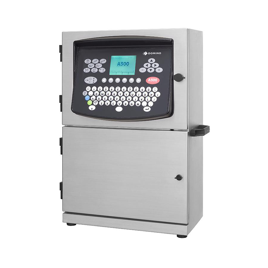
- Manuals
- Brands
- Domino Manuals
- Printer
- A-SERIES
- Operation and maintenance manual
-
Contents
-
Table of Contents
-
Bookmarks
Related Manuals for Domino A-SERIES
Summary of Contents for Domino A-SERIES
-
Page 1
DOMINO A—SERIES INK JET PRINTER OPERATION AND MAINTENANCE MANUAL… -
Page 2: Declaration Of Conformity
DECLARATION OF CONFORMITY Domino UK Ltd, Bar Hill, Cambridge CB3 8TU declare under our sole responsibility that the products, Domino A300 and Pinpoint, A200 & A100 Printers to which this declaration relates, are in conformity with the following standards: EN50081—2 1992 Class B : Electromagnetic Compatibility…
-
Page 3
INK JET PRINTER OPERATION AND MAINTENANCE MANUAL This manual, Domino Part No. 27080, is for use in the maintenance of Domino A300 and Pinpoint, A200 and A100 printers. For instructions on how to operate the printer, refer to the Domino A—Series Operator’… -
Page 4: Fcc Notice
FCC Notice This equipment has been tested and found to comply with the limits for a Class A digital device, pursuant to Part 15 of the FCC Rules. These limits are designed to provide reasonable protection against harmful interference when the equipment is operated in a commercial environment.
-
Page 5
DOMINO A—SERIES INK JET PRINTER OPERATION AND MAINTENANCE MANUAL CONTENTS CHAPTER 1 Part 1 Health and Safety Basic requirements and symbol explanations. Part 2 Introduction Including printer specification, menu map and use of the front panel. CHAPTER 2 Part 3… -
Page 6
27080 Issue 1 Sept 98… -
Page 7
DOMINO A—SERIES INK JET PRINTER OPERATION AND MAINTENANCE MANUAL AMENDMENT RECORD Amendment Date All Parts at Issue 1 September 98 Appendix B : Compressor Driven Airdryer April 98 Appendix B : Air Driven Airdryer April 98 27080 Issue 1 Sept 98… -
Page 8
27080 Issue 1 Sept 98… -
Page 9
DOMINO A—SERIES INK JET PRINTER OPERATION AND MAINTENANCE MANUAL In order that the machine continues to comply with the standards required by the certification, the following components must not be altered in any way or replaced by other types. COMPONENT DOMINO MANUFACTURER MANUFACTURER PART NO. -
Page 10
(10) 27080 Issue 1 Sept 98… -
Page 11: Table Of Contents
PART 1 : HEALTH AND SAFETY CONTENTS INTRODUCTION ……..Page 1—3 Basic Requirements .
-
Page 12
HEALTH AND SAFETY 1—2 27080 Issue 1 August 98… -
Page 13: Part 1 : Health And Safety
HEALTH AND SAFETY HEALTH AND SAFETY INTRODUCTION Domino supplies Safety Data Sheets (SDS’ s)giving specific safety information with each of its ink, make—up and wash fluids. There are also warnings on each container. The following notes are for general guidance only.
-
Page 14: Storage
HEALTH AND SAFETY Many inks contain materials which vaporise easily and can be inhaled. Good ventilation is necessary Any used cleaning materials, e.g. rags, paper wipes, are a potential fire hazard. They must be collected for safe disposal after use After exposure to ink, all possible traces must be washed off as soon as possible at the nearest washing facility.
-
Page 15
HEALTH AND SAFETY If dry Nitro—cellulose based ink ignites, it will generate its own oxygen and can only be extinguished by lowering the temperature with water Nitro—cellulose fire occurs, ENSURE THAT THE ELECTRICAL POWER IS IMMEDIATELY REMOVED FROM THE PRINTER BEFORE water is used to extinguish the fire. Fire risk is a most important consideration where printing inks are stored and used. -
Page 16: Spillages And Disposal
HEALTH AND SAFETY Spillages and Disposal WARNING: Some dried inks are highly flammable. Clean up all ink spillages immediately. Do not allow the ink to dry or allow any build—up of dried ink spills. Spillages must be cleaned up as soon as possible with the appropriate solvent materials and with regard to the safety of personnel.
-
Page 17: Symbols
HEALTH AND SAFETY SYMBOLS The following symbols are used in this manual. Where they appear next to a procedure or instruction, they have the significance and importance of written warnings and cautions. Eye protection must be worn. Protective clothing must be worn. The equipment must be switched off and power removed.
-
Page 18
HEALTH AND SAFETY 1—8 27080 Issue 1 August 98… -
Page 19
PART 2 : INTRODUCTION CONTENTS GENERAL ……… . Page 2—5 PRINTER SPECIFICATION . -
Page 23: Part 2 : Introduction
INTRODUCTION INTRODUCTION GENERAL This manual provides: A basic introduction to the printer and how to use the front panel, with procedures that demonstrate how to manage the printer Reference sections describing the functions and messages presented through the front panel A full description of the ink and electronics systems Maintenance and repair procedures.
-
Page 24: Printer Specification
INTRODUCTION PRINTER SPECIFICATION Print Head Standard Finish: Aluminium alloy, Tufram coated Dimensions: Width: 40mm (1.575”) Depth: 42.5mm (1.673”) Height: 280.5mm (11.05”) Weight: 1.0kg (2.2lbs) Nozzle size: 60 or 75 micron Pinpoint only: 40 micron Spacing from print surface: 12mm (0.47”) nominal Pinpoint only: 4mm (+/— 1mm) Working height relative to…
-
Page 25: Ink System
INTRODUCTION Ink System Ink Capacity (Reservoir): 1.2 litres (0.32 US gall.) — automatically metered Ink Capacity (Cartridge): 825ml (0.218 US gall.) Make—up Capacity 600 ml (0.16 US gall.) nominal — (Reservoir): automatically metered Make—up Capacity 825ml (0.218 US gall.) (Cartridge): Ink Viscosity Control: Automatic Viscometer Ink Bleed Control:…
-
Page 26: Printer Control
INTRODUCTION PRINTER CONTROL The printer is switched on by pressing the black button—switch on the side of the cabinet. This supplies power to the whole printer and after a short period control of the printer is transfered to the front panel. Control Panel The printer is controlled exclusively through the front panel.
-
Page 27: On/Off Switching
INTRODUCTION Alert Bar Screen Number Status Bar Working Area Print Symbol Information Bar Scroll Arrow Key Option Bar simultaneously, the highest priority alert is displayed. unacknowledged alert is always at a higher priority than any other acknowledged alert. Screen messages are detailed in Part 4. Status bar shows status and other non—alert information.
-
Page 28
INTRODUCTION Red Alert Power On Indicator Indicator Amber Alert Indicator Green Jet On/Off Indicator displays steadily when the alert is acknowledged. It is extinguished when the fault is cleared. Amber Alert Indicator shows the printer has a fault that requires attention. -
Page 29: Topic Keys
INTRODUCTION Topic Keys The topic keys each open sets of screen options. These are shown in the diagram on pg. 2—8 and described in detail in Part 5 : Reference. Message Editor Provides access to the message creation utilities. Message Store Provides access to the stored Messages.
-
Page 30: General Purpose Keys
INTRODUCTION General Purpose Keys Cursor Keys Four permanent keys used to move the cursor around the screen. Increment Keys Two permanent keys used to increment and decrement values shown on the screen and marked with the highlight bar. The effect of these keys on settings and values is immediate.
-
Page 31: Help Key
INTRODUCTION Help Key Help Key Provides access to help information concerned with the current menu screen. Currency Key Currency Key Provides entry for localised currency characters. Pressing this key generates the minor currency symbol (e.g. p,c) and pressing it in combination with the Shift key generates the major currency symbol (e.g.
-
Page 32: Unicode Character Entry
INTRODUCTION The following table shows the available password protection: LEVEL PASSWORD REQUIRED Lockout None Message Monitor None Message Editor Supervisor Message Store Supervisor Print Setup Supervisor Memory Card Supervisor Machine Setup Supervisor Service Service Unicode Character Entry Characters that are not represented by a key can be available for printing.
-
Page 33: Front Panel Topic Key Menus
MESSAGE EDITOR Font Dblspace Insert Print Insert Bold Shift Text Clock Serial Edit Size On/Off Logo Message Clock On/Off Code Field Offsets Number Message (pg.5—8) (pg.5—8) (pg.5—9) (pg.5—9) (pg.5—11) (pg.5—11) (pg.5—11) (pg.5—12) (pg.5—12) (pg.5—12) (pg.5—13) (pg.5—13) Message Editor (Cont.) Start Toggle Special Text…
-
Page 34
PRINT SETUP Message Reverse Print Reset Inverse Repeat Enable Change Change Bold Control Delay Serial# Control Printing Printing Height Width (pg.5—26) (pg.5—26) (pg.5—26) (pg.5—26) (pg.5—27) (pg.5—28) (Pg.5—27) (pg.5—28) (pg.5—29) MACHINE SETUP Time Password Beeper Master Product Month Serial Alpha Format Currency Setup Clock… -
Page 35
PART 3 : OPERATION CONTENTS START—UP ……… . Page 3—3 SHUT DOWN . -
Page 36
OPERATION 3—2 27080 Issue 1 August 98… -
Page 37: Start—Up
Status bar message changes to Printer Off and the green indicator stops flashing and remains off. Either A300, A200, A100 (depending on printer type) or Domino Logo is displayed on the screen. The printer is now ready for the jet to be switched on.
-
Page 38: Ink Reservoir Replacement
OPERATION Reservoir Replacement INK RESERVOIR REPLACEMENT The messages Ink change needed in less than 24 hours and, later, Ink change needed in less than 2 hours will appear near the end of the reservoir life (If a long—life system is being used, these warnings will appear at 300 hours and 24 hours before the end of reservoir life).
-
Page 39
OPERATION Manifold Retainer Reservoir Retaining Bar MG187—1 MG188—1 Removing the Ink Reservoir Reservoir Retaining Bar MG189—1 Refitting the Ink Reservoir 27080 Issue 1 August 98 3—5… -
Page 40: Ink And Make—Up Cartridge Replacement
OPERATION INK AND MAKE—UP CARTRIDGE REPLACEMENT Note: If only small amounts of ink are being used by the printer, it may not be necessary to fit an ink cartridge. Leave the ink manifold seal in place and only fit an ink cartridge when a request appears on the display.
-
Page 41: Creating A Message
OPERATION CREATING A MESSAGE The following shows how to create and print a message. The suggested entries could be used as a working example. All of the screens Create Message presented on the display are fully described in Part 5 : Reference. Display Contrast For comfort, the display contrast can be adjusted by pressing the blue alternative character set key and adjusting the contrast using the…
-
Page 42: To Print The Message
OPERATION The key labels along the bottom of the screen may not show the required options immediately. If necessary, use the scroll keys (see pg. 2—12) to move the options across the screen. To select the option, press the key below the label on the screen. To Create the Message (1) Press the Message Editor topic key.
-
Page 43: To Select An Existing Message
OPERATION message names may extend off the screen — continuing to use the cursor key will automatically scroll the list. Note: A message being currently used for printing (marked ”>”) cannot be deleted. (3) Select Delete Message from the key options. The screen will change Delete Message to show Delete message? and the message name.
-
Page 44
OPERATION (4) Use an increment key to change the date format in the highlight bar to a suitable format. (5) Select OK from the key options. The display will change to show the message with the clock detail inserted at the cursor position. Clock entries on the display will not be updated. -
Page 45: To Enter A Serial Number
OPERATION To Enter a Serial Number (1) With Message Editor selected, press the scroll keys to search the key options and select Serial Number. Select Message The screen will change to show the parameters controlling the serial numbering. These include the start number (first limit), finish number (second limit) and the change between messages (step size).
-
Page 46: To Enter A Shift Code
OPERATION Lower Character: ..Upper Character: ..Start Value: ..(5) Select OK from the key options. To Enter a Shift Code (1) With Message Editor selected, press the scroll keys to search the function key options and select Shift Code.
-
Page 47: To Create A Machine Readable Code
OPERATION To Create a Machine Readable Code (MRC) (A300/A200 only) The following procedure is carried out in Message Editor, either as a new message or as part of a message being constructed. During the following procedures, decisions on the following will be required: (a) MRC type (b) MRC data which is appropriate to the MRC type…
-
Page 48
OPERATION (3) Type in the MRC message. (4) Press End MRC option key. The screen will change to show the MRC Identifier i.e. whether the barcode is the first, second, etc. in the message, and the MRC type. (5) If necessary, use the increment keys to change the MRC setting to the required type. -
Page 49
OPERATION text is to be fitted into the indentation, it is important that this is a height suitable to fit into the indentation (or the text will be fitted outside the barcode). Then use the cursor keys to move the cursor to the required position. -
Page 50
OPERATION To Create A Dot Code: Follow steps under ’ Create a Machine Readable Barcode’up to step (5), then continue as follows: (6) Select the required code (Snowflake or Data Matrix) and press the Advanced key. (7) Select the required Dot Code parameters in this screen. These are as follows: Format which describes the type of data to be encoded, options are: SNOWFLAKE… -
Page 51
OPERATION Snowflake Encryption Capacities 10% Error Code Correction DENSITY DENSITY MAXIMUM CHARACTER ENCRYPTION CAPACITY Numeric Upper Lower Punctuation Alphanumeric Format 1 Case Case Format 4 Format 5 Format Format 7 x 16 7 x 24 8 x 8 9 x 9 10 x 10 11 x 11 11 x 24… -
Page 52
OPERATION 14 x 14 15 x 15 16 x 16 16 x 24 40% Error Code Correction DENSITY DENSITY MAXIMUM CHARACTER ENCRYPTION CAPACITY Numeric Upper Lower Punctuation Alphanumeric Format 1 Case Case Format 4 Format 5 Format Format 7 x 16 7 x 24 8 x 8 9 x 9… -
Page 53: Issue 1 Sept
OPERATION Data Matrix Square Encryption Capacities Error Code Correction 50 DENSITY DENSITY MAXIMUM CHARACTER ENCRYPTION CAPACITY Numeric Format 1 Alphanumeric ASCII Format 3 Format 2 11 x 11 13 x 13 15 x 15 16 x 16 Error Code Correction 80 DENSITY DENSITY MAXIMUM CHARACTER ENCRYPTION CAPACITY…
-
Page 54: Introduction 1
PART 4 : DISPLAY MESSAGES AND FAULT FINDING CONTENTS INTRODUCTION ……..Page 4—3 Red alerts .
-
Page 55
DISPLAY MESSAGES AND FAULT FINDING 4—2 27080 Issue 1 August 98… -
Page 56
DISPLAY MESSAGES AND FAULT FINDING DISPLAY MESSAGES AND FAULT FINDING INTRODUCTION There are separate bars on the display showing: alert messages (see below) status messages (see pg. 4—14) Information messages (see pg. 4—16). Red Alerts Red alerts are shown by a flashing red LED indicator on the jet on/off switch and a message flashing in the alert bar (see pg. -
Page 57
DISPLAY MESSAGES AND FAULT FINDING Fault Acknowledgement Alert bar messages flash until acknowledged by pressing any character key or the space key, after which the message is displayed continuously. Depending on the alert, some messages are cleared when the condition is cleared. -
Page 58
Cabinet overheated Cabinet temperature is too high. Ensure printer is operating within specified temperature environment. Check air filter. If fault persists, call Domino Service. Cabinet temperature sensor input error Failure at input to sensor. If fault persists, call Domino Service. -
Page 59
EEPROM write failed The EEPROM (a hardware device used by the printer to store the ink life data) has failed. If fault persists, call Domino Service. Excess pump overspeed Ink pressure is being maintained but pump speed is excessive. Check ink system for leaks or worn pump. -
Page 60
Gutter dry Ink not entering gutter. Check jet alignment. Check that nozzle is not blocked. Head temperature sensor input error Failure at input to sensor. Check sensor connections. If fault persists, call Domino Service. 27080 Issue 1 August 98 4—7… -
Page 61
DISPLAY MESSAGES AND FAULT FINDING Ink temperature sensor input error Failure at input to sensor. Check sensor connections. If fault persists, call Domino Service. Ink change due — replace ink reservoir Ink life has expired. Fit new reservoir before printing can be restarted. -
Page 62
Ink heating system has failed. Check heater connections and check thermistor. Ink level sensor input error Failure at input to sensor. Check sensor connections. If fault persists, call Domino Service. Ink pressure loss Pressure loss due to leakage, pump failure or transducer failure. -
Page 63
DISPLAY MESSAGES AND FAULT FINDING Ink temperature low Ink temperature is outside control system limits. Ensure printer environment is within specification. Invalid or missing Font file Font file missing or corrupted. Replace the font file. Invalid or missing Raster file Raster file is either missing or corrupted. -
Page 64
If message does not correspond to a configuration change, call Domino Service. Pressure sensor input error Failure at input to sensor. Check sensor connections. If fault persists, call Domino Service. Print data generated too late Print rate too fast. Adjust print delay. -
Page 65
Check battery. Reset by watchdog Internal error. If fault persists, call Domino Service. Solvent level sensor input error Failure at input to sensor. Check sensor connections. If fault persists, call Domino Service. 4—12 27080 Issue 1 August 98… -
Page 66
DISPLAY MESSAGES AND FAULT FINDING Too many products, some ignored Messages have been queued more frequently than products are being detected. Some messages will be lost. Too much ink Ink level is above maximum. Remove ink from the reservoir. Too much make—up Make—up level is above maximum. -
Page 67
DISPLAY MESSAGES AND FAULT FINDING STATUS BAR MESSAGES Status Bar The following status messages may be displayed: Fault condition The printer encountered a fault that it was unable to recover from. In general, this state is entered after the printer has shut down following an unsuccessful fault recovery attempt. -
Page 68
DISPLAY MESSAGES AND FAULT FINDING Modulating The printer has entered an intermediate state where the jet is running and modulation is enabled. This intermediate state is only reported when sequencing is controlled via the Service Mode. Modulation reset The printer is attempting to automatically reset the modulation level. -
Page 69
DISPLAY MESSAGES AND FAULT FINDING Sequencing Off The printer is sequencing off. During normal operation, this state may be reported if the operator has requested sequence to off, i.e. the printer was Ready to Print and the Jet On/Off key was pressed for two seconds. -
Page 70: Printer Faults
DISPLAY MESSAGES AND FAULT FINDING PRINTER FAULTS The following problems can have the suggested causes and remedies. No Indicators Showing Power failure. Restore power. Fuse failure. Replace fuse (see pg. 8—22). Machine Does Not Print Message faulty. Check data entry. Product detector disconnected or faulty.
-
Page 71
DISPLAY MESSAGES AND FAULT FINDING Print Size Too Small Character height adjustment incorrect. Adjust print height. Jet alignment with deflector plates incorrect. Check jet alignment. Ink Pressure too high. Check and reset pressure if required. Solvent on deflector plates (after cleaning). Dry deflector plates. -
Page 72
DISPLAY MESSAGES AND FAULT FINDING PRINT QUALITY FAULTS The following are examples of faulty printing. In most cases, further investigations should begin with ensuring that the print head is clean and properly aligned. Head not mounted at 90 degrees to direction of product movement. TP3060—1 Head too far from print surface. -
Page 73
PART 5 : REFERENCE CONTENTS GLOSSARY OF TERMS ……. Page 5—5 Print Definitions . -
Page 74: Storage 1
REFERENCE Product Select # ……..5—20 Raster .
-
Page 75
REFERENCE Ink Data ……….5—32 Product Counter . -
Page 76
REFERENCE 5—4 27080 Issue 1 August 98… -
Page 77: Glossary Of Terms
REFERENCE REFERENCE Glossary of Terms Alphanumeric Letter or number characters. Attribute A characteristic, or distinctive feature. Ball Fall Time. The time taken for the ball in the viscometer to descend through the sample of ink in the viscometer tube. Break up point, below nozzle plate and within charge electrode, where jet breaks into drops.
-
Page 78: Print Definitions
REFERENCE Status Information presented by the printer — the current value, setting or adjustment in the printer. Stroke The adjacent lines of ink drops making up the character drop matrix. The distance between strokes is sometimes used as a unit of measurement in spacings or delays.
-
Page 79: Screen Descriptions
REFERENCE SCREEN DESCRIPTIONS Following is a reference section of screens appearing on the front panel display, Each description consists of: a representative illustration with a general explanation Screen content (in italics): specifying the options, values, etc. Options: explaining the options where these are not immediately apparent Function key options: explaining the options offered through the soft keys.
-
Page 80: Message Monitor
REFERENCE MESSAGE MONITOR Shows the messages as they are printed. A displayed message cannot be edited, but is updated each time the message is printed (up to the maximum display refresh rate) and shows the true value of printed serial numbers and clock fields.
-
Page 81: Insert Clock
REFERENCE Insert Clock Permits clock information to be inserted into the message at the cursor position. The format of the clock information and offsets to the time can be selected from a range of options. Clock Offset Number: Enter 1—4 (or 1—2 on A100)(see pg. 5—13) Format: Select DD MM YYYY / DD/MM/YY / DD/MM/YYYY / Date / Day name / Day…
-
Page 82: Advanced Serial Number
REFERENCE Function key options: Cancel Return to previous menu without entering serial number. Enter serial number information into message. Advanced Open menu enabling complex serial numbers. Advanced Serial Number Enables alphanumeric serial Advanced numbers to be created. Alpha stepping will be reversed if the first limit is beyond the second limit.
-
Page 83: Edit
REFERENCE Edit Permits the editing of any part of the message such as individual characters, clock entries, serial numbers, etc. The required part of the message is selected by marking with the highlight bar. The screen detail may be as shown. However, more appropriate screen detail will be shown if required by the function selected for editing.
-
Page 84: Dblspace On/Off
REFERENCE DblSpace On/Off Press the function key and all items subsequently inserted in the message will be double—spaced. Press the key again to discontinue double—spacing. (This key does not cause the entire message to be printed in double spacing — see pg. 5—26). Shift Code Permits creation of shift code information and inserts it into the…
-
Page 85: Text Field
REFERENCE Text Field Permits the insertion of an open area in the message allowing, for example, other pre—printed information show clearly through the message. Text Field Length: Enter length in character widths. Function key options: Cancel Return to previous menu without creating or amending a text field.
-
Page 86: Start Mrc
REFERENCE Start MRC (A300/A200 only) Inserts a marker indicating the start of the MRC. Subsequent entries into the message will be included in the MRC, until End MRC is selected. The marker is shown on the screen by a ”>” symbol. End MRC(A300/A200 only) Inserts the marker indicating the end of the MRC.
-
Page 87: Mrc Text
REFERENCE Indentation Width: Enter 0—59. Height: Enter number of print lines. Check Digit: Select Default/None/Mod10 Factor3/Mod10 Factor 3 Alt/Modulus 43/Modulus 103 . Invert/Normal: Select Invert/Normal. Quiet Zone Width Left: Enter 0—59. Quiet Zone Width Right: Enter 0—59. Element Width: Enter number of strokes to be used to create the barcode element.
-
Page 88: Toggle Mrcs
REFERENCE Toggle MRCs (A300/A200 only) Permits switching the display between the MRC and the characters represented by the MRC. Special Setup Messages are printed according to two groups of settings — the special settings associated with a particular message and the general (global) settings used by the printer.
-
Page 89: Reverse Control
REFERENCE Reverse Control Permits reverse printing of each Special message. This will be applied to all Setup messages unless dynamic control is used, which case reverse printing can be alternately applied and suspended to specified counts of messages. Reverse Orientation Select On/Off/Use Global Function key options: Cancel…
-
Page 90: Counted Products
REFERENCE Function key options: Accept special settings. Cancel Discard new settings and return to Special Setup screen. Static Control: Abandon dynamic control and return to Dynamic Control screen. Counted Products Opens Counted Products screen —see below. External Port Provides access to external control settings. Counted Products Permits setting…
-
Page 91: Repeat Printing
REFERENCE Repeat Printing Permits selection of continuous printing, or repetitive counts to a Special Setup specified number and pitch value, or global settings entered through Print Setup. Message contents such clocks, shift codes, serial numbers, etc, can be updated every time a message is printed or only when a new product is detected.
-
Page 92: Product Select
REFERENCE Function key options: Cancel Discard changes. Accept new settings. Product Select # Permits allocation of a number to identify the message. This allows a Special Setup range of messages to be available for printing according to selection by number through the User Port. Product Select Number Enter 0—255.
-
Page 93: Message Store
REFERENCE MESSAGE STORE Access to Message Store can be controlled by password (see pg.2-13). Provides access to the message store and is closely linked with the Message Editor. Select Message Permits selection from alphabetical listing of the stored messages. If a message is already selected for editing, selection of another message is accompanied by a warning that the current message could be lost.
-
Page 94: Save Message
REFERENCE Save Message Permits entering the message into the message store under a message name. A warning is provided if the message name is already used in the store. Save current message as: Enter message name up to 64 characters long. Function key options: Cancel Return to previous menu without saving…
-
Page 95: Storage Stats
REFERENCE Storage Stats Displays message store information as shown. Key Option: Exit Return to previous menu. Export Message Permits export of a message as a file to a PCMCIA card or the printer internal RAM disk. (Always wear a wrist strap when working in the electronics cabinet).
-
Page 96: Import (R:\)
REFERENCE Import (r:\) Permits import of a message from the printer’ s internal RAM disk for direct use in printing. Function key options: Cancel Discontinue procedure. Continue procedure. Logo Store Permits inspection and control of the store from which logos can be selected insertion into…
-
Page 97: Storage Stats
REFERENCE Storage Stats Provides statistics for the logo store. Logo Store Export Logo Permits export of a logo onto the PCMCIA card or to the printer’ s Logo Store RAM disk. Path identity for the RAM disk is r: Path identity for PCMCIA card is p: Import (p:\) Permits import of a logo from the PCMCIA card into the logo store.
-
Page 98: Print Setup
REFERENCE PRINT SETUP Access to Print Setup can be controlled by password (see pg. 2—13). Provides access to default or global options which control the way all messages are printed. Message may, however, contain individual settings entered through Message Editor (see pg. 5—16) that override these global settings.
-
Page 99: Enable Printing
REFERENCE Update Numbers for each Repeat: Select Yes/No. Use Product End: Select Yes/No to select if repeats are to be terminated by detection of the end of the product. Function key options: Cancel Discard changes. Accept new settings. Enable Printing Permits printing to be enabled under control of the product detector input.
-
Page 100: Reset Serial Number
REFERENCE Reset Serial # If the current message does not contain any serial numbers this key will not be active. Displays the current values of any serial numbers contained in the message currently being printed. The printed output can be edited with new values or reset to the original values.
-
Page 101: Change Width
REFERENCE Change Width Permits adjustment of the width of printed characters. The adjustment is only effective with internal stroke generation. If stroke generation is external, the width is displayed but is adjusted by shaft encoder selection and the external stroke divider ratio (see pg. 5—41).
-
Page 102: Memory Card
REFERENCE MEMORY CARD Access to Memory Card can be controlled by password (see pg.2-13). Provides export and import of messages and logos between the printer and the PCMCIA card fitted into the slot on the Control PCB Assembly (always wear a wrist strap when working…
-
Page 103: Machine Setup
REFERENCE MACHINE SETUP Access to Machine Setup can be controlled by password (see pg.2-13). Provides access to options which affect the operation of the printer. Master Clock Permits setting of the real—time clock in the printer. Only valid times and dates can be entered. Year: Enter 1970—2038.
-
Page 104: Ink Data
REFERENCE Ink Data Provides a display of the current ink data. Cartridge, reservoir and wash details depend upon the ink in use. Ink Life Setting: Shows ink life. Ink Life Remaining: Remaining hours before ink reservoir life expiry. Function key options: Exit Return to previous screen.
-
Page 105: Month Names
REFERENCE Month Names Permits editing of the month names used in the clock information inserted into a message using the message editor. Month 1, 2 . .: Enter up to 28 alphanumeric characters. Function key options: Cancel Discard changes. Save to Message Use new settings in current message only. Save as Default Retain new names for use in new messages.
-
Page 106: Password Setup
REFERENCE Date (01 to 31). Julian date (001 to 366). Julian year (0 to 9). Year (00 to 99). Year (1970 to 2038). Month (01 to 12). Month name (see pg. 5—33). Hours (00 to 23). Quarter hours (01 to 96). Day name (see pg.
-
Page 107: Set Currency
REFERENCE Set Currency Permits setting up the currency entries made with the currency key. Thus, currencies which are not represented directly keyboard can still be made single key entries. The major and minor denominations are carried as the upper and lower case currency key entries.
-
Page 108: Service
REFERENCE SERVICE Provides access to printer functions for trained personnel. Access to Service is controlled by password (see pg. 2—13). Enter the correct password and select OK. (An incorrect password must be removed using the delete key before a revised password is entered).
-
Page 109: Print Head
REFERENCE Machine Time: Total time printer has been switched on — hours:minutes. Jet Time: Total time jet has been switched on — hours:minutes. Options: Fixed Previously saved modulation set point used for modulation voltage. Auto Set Select for automatic modulation set—up. This is not subsequently tracked and may require re—setting due to temperature variations.
-
Page 110: Ink System
REFERENCE Target Temp: Range: 26—50 C gunbody target temperature, dependant upon ink type. Actual Temp: Within +/—5 C of gunbody target temperature, with printer at working temperature. Options: Fixed Previously saved modulation set point used for modulation voltage. Auto Set Select for automatic modulation set—up.
-
Page 111: Viscosity
REFERENCE Gutter State: Status: Wet/Dry. Pump Speed: Range: 1700—2300 rpm depending upon ink type. Regulation: Status: Pressure/Vacuum/Disabled. Target BFT: Dependent upon ink type (seconds). Actual BFT: Result of last viscosity measurement (seconds). Ink Temp: Range: 5—55 C, depending upon ink type. Mod’…
-
Page 112
REFERENCE Actual BFT: Result of last viscosity measurement (seconds). Target BFT Dependent upon ink type (seconds). VOR Upper: Range: upper limit on BFT (seconds). VOR Lower: Range: lower limit on BFT (seconds). Make—up Valve: Status: Open/Closed. Visc Valve: Status: Open/Closed. Peltier Mode: Status: Off/On/Auto. -
Page 113: External I/F
REFERENCE External I/F Permits control of the external interface (product detection and stroke control). Stroke control is directly selectable as internal or external (external is normally a shaft encoder). Internal product detection is selected through the Product Sequence function key option.
-
Page 114: Config
REFERENCE Config Provides general printer information. Also, by pressing the down cursor key, the screen changes to give software details. Config A value representing the printer configuration used in reports on the printer. Ink Type: Ink type used in printer. Nozzle : Nozzle diameter and drive rod frequency.
-
Page 115: Event Log
REFERENCE Event Log Lists the last 50 system events which have been logged, starting with the most recent. Date, time and the alert status (Raised, Acknowledged or Cleared) is shown with each event. Events are recorded as DDMM hhmm x — (details), where: Range: 1—31 days.
-
Page 116: Backup Printer
REFERENCE Backup Printer This function down—loads the printer settings onto a specially formatted PCMCIA card, to provide a back—up record of the printer configuration. The card can then be held for use in restoring the settings in the printer after repair, or setting up another printer for similar operation.
-
Page 117
PART 6 : PRINTER DESCRIPTION CONTENTS PRINT HEAD ……..Page 6—3 General Principles . -
Page 118
PRINTER DESCRIPTION Conduit Upper Wiring and Connector Compartment Holster Securing Screw Head Valve Drop Generator Charge Electrode Deflector Plates Gutter Drop Generator Charge Electrode Magnifier Deflector Gutter Plates TP1251_1 Pinpoint print head MG055—2 Print Head — General View 6—2 27080 Issue 1 September 98… -
Page 119: Part 6 : Printer Description
PRINTER DESCRIPTION PRINTER DESCRIPTION PRINT HEAD General Principles Each printed character consists of a dot matrix made up of lines, or strokes, of ink Drops drops. The ink drops in each stroke are spaced apart by electronic deflection and the Unused Positions strokes are spaced apart by the movement of…
-
Page 120
PRINTER DESCRIPTION The print head slides into a protective holster and is locked into place by a screw in the rear. The holster is mounted in the printing position and contains precision guide rails to ensure that the print head always returns to exactly the same position if the print head is removed and replaced. -
Page 121: Cabinet
PRINTER DESCRIPTION Gutter. Ink caught in the gutter is drawn back into the ink system for re—use by a pump in the cabinet. The gutter system in the head consists of the gutter pipe, a short length of tube, and a gutter sensor consisting of a length of pipe electrically isolated from the chassis.
-
Page 122
PRINTER DESCRIPTION CAUTION The printer must not be operated with the ink chassis removed. In the lower compartment, operations such as replacing cartridges and reservoirs are carried out through the open door. However, the ink system is mounted on a chassis, enabling it to be removed as a single assembly. -
Page 123
PRINTER DESCRIPTION External Mains Interface Filter Power Front Panel Supply Ink System Interface PCB HV Power Front Panel Supply Cover (not shown) Filter Assembly Control PCB Assembly Ink Management Viscometer Block A300/A200 Cabinet — General View(1) MG002—2 27080 Issue 1 September 98 6—7… -
Page 124
PRINTER DESCRIPTION Front Panel Cover Filter Air Pump or Pressure Switch (Options) Securing Latch Solenoid Valves Cartridge Peltier Condenser Assembly Reservoir (Optional on A200) Make—up Pump Reservoir Make—up Cartridge MG003—2 A300/A200 Cabinet — General View (2) 6—8 27080 Issue 1 September 98… -
Page 125
PRINTER DESCRIPTION External Mains Interface Filter Power Front Panel Supply Ink System Interface PCB HV Power Front Panel Supply Cover (not shown) Filter Assembly Control PCB Assembly Ink Management Viscometer Block A100 Cabinet — General View (1) A1001_1 27080 Issue 1 September 98 6—9… -
Page 126
PRINTER DESCRIPTION Front Panel Cover Filter Air Pump (Option) Solenoid Valves Peltier Assembly (Optional on Cartridge A100) Reservoir Pump Make—up Make—up Reservoir Cartridge A1002_1 A100 Cabinet — General View (2) 6—10 27080 Issue 1 September 98… -
Page 127
PRINTER DESCRIPTION Air Supply Pressure Switch EXTERNAL INTERFACE Positive Air Power Supply Input INK SYSTEM Temperature INTERFACE Viscometer Fluid Level MAIN Detection Solenoid Valves Pump Power to Print Engine Controller Pressure Measurement Peltier Gutter FRONT Sensor PANEL Charge Electrode Charge Detector Nozzle Valve… -
Page 128: Electronics System
PRINTER DESCRIPTION ELECTRONICS SYSTEM All operator control, maintenance and fault reporting is carried out via the front panel in communication with the electronics system shown in the diagram opposite. The electronics system is centred on the Control Printed Circuit Board (PCB) Assembly, consisting of the Printer Supervisor, Stroke Generator and Print Engine Controller.
-
Page 129
PRINTER DESCRIPTION voltages required for drop charging (295V nominal), ink stream modulation (210V nominal) and drop deflection (+/—4kV nominal or +/—3.65kV Pinpoint). The drop deflection voltage has a very high source impedance, eliminating any hazard if touched. Software support is supplied via a PCMCIA card connector, providing the means of loading software, upgrading software and downloading data such as error logs, printer configuration information, logos and message back—ups. -
Page 130: Power Off
PRINTER DESCRIPTION Power Off (No power applied to printer) Power On Power Off Printer Off (Power applied — printer intialised — pump not running) Jet On Jet Off Ready to Print (Jet running) Printer Automatic Sequencing 6—14 27080 Issue 1 September 98…
-
Page 131
PRINTER DESCRIPTION Peltier Ink Management (Optional on Block A200/A100) 1psi PRV & Temperature Sensor Over—pressure Viscometer Make—up Main Filter Reservoir Gutter and Make—up MG016_2 Filters Behind Reservoirs Ink Reservoir Pressure Transducer Jet Pump Reservoir Manifold Solenoids Cartridge Make—up Cartridge Main Pump MG017_1 Ink System — General Views… -
Page 132: Ink System
PRINTER DESCRIPTION INK SYSTEM General CAUTION The Ink system must never be withdrawn from the cabinet with the printer running. The ink system supplies the printhead with ink at the correct pressure and viscosity. When the jet is stopped, the system also flushes out the print head with make—up to provide a clean stop and, when the jet is next switched on, a clean start.
-
Page 133
Pressure Bleed Management Transducer Valve Bleed Block Wash Feed Feed Over—pressure Pump Valve Valve Filter PRV (100psi) Gutter 1psi Filter Make—u p Valve Main Flush Filter Valve Pump Nozzle Valve Viscometer Make— MAKE— Filter Visc. Valve 1/4” Tube Printhead 1/8” Tube Vent Ink System — Circuit Diagram MG027_4… -
Page 134
PRINTER DESCRIPTION Feed circuit. Ink from the reservoir is supplied to the circuit by the high pressure pump. The ink is pumped through a 5 micron filter, a jet pump and then through a 69 mbar (1psi) Pressure Relief Valve (PRV) and back into the reservoir. -
Page 135
PRINTER DESCRIPTION through stationary ink. Its movement down the tube is timed and this time is used as the viscosity check. If the ink is too thick, make—up is added into the ink reservoir by opening the make—up solenoid valve. The suction provided by the low pressure (gutter) pump head then draws in make—up from the make—up reservoir and passes it with the gutter ink into the reservoir. -
Page 136
PRINTER DESCRIPTION 6—20 27080 Issue 1 September 98… -
Page 137
DESCRIPTION 37700W Iss. 1 PELTI- Wiring Diagram 27080 Issue 1 August 98 6—21… -
Page 138
DESCRIPTION 6—22 27080 Issue 1 August 98… -
Page 139
PART 7 : MAINTENANCE CONTENTS PREVENTATIVE MAINTENANCE ….Page 7—3 Ink System — Access ……..7—3 Preventative Maintenance Reports . -
Page 140: Part 7 : Maintenance
MAINTENANCE 7—2 27080 Issue 1 Sept 98…
-
Page 141: Preventative Maintenance
Changing of the ink type in the printer. Preventative Maintenance falls into the following two categories: Procedures that can be carried out by the operator Procedures which must only be carried out by Domino trained personnel. (This is indicated by the symbol shown in the margin) However, Domino recommends that all maintenance procedures are carried out by Domino trained personnel.
-
Page 142
MAINTENANCE 7—4 27080 Issue 1 Sept 98… -
Page 143: Preventative Maintenance Reports
MAINTENANCE PREVENTATIVE MAINTENANCE REPORT Serial Number Run Hours Date M/C Configuration 2000 4000 6000 8000 (1) Replace Filters: (a)Make—up/Flush (b)Gutter (c)Main (d)Feed (2) Replace Air Filter (3) Check Manifold Seals Replace Manifold Seals (4) Check Operation: (a)Cooling Fan (b)Positive Air Pump (5) Ink Information: (a)Ink Temp (b)Actual BFT…
-
Page 144
MAINTENANCE Note: The following procedures must only be carried out by Domino trained personnel. 2000 4000 6000 8000 (9) Printhead Settings: (a)Jet Into Gutter Alignment (b)Printhead Alignment Checks (10) Pressure Window Check (11) Modulation Window Check (12) Pump Speed Check… -
Page 145
MAINTENANCE PINPOINT ONLY PREVENTATIVE MAINTENANCE REPORT Serial Number Run Hours Date M/C Configuration Every 1800 3600 5400 7200 600hrs (1) Replace Filters: (a)Make—up/Flush (b)Gutter (c)Main (d)Feed (2) Replace Air Filter (3) Check Manifold Seals Replace Manifold Seals (4) Check Operation: (a)Cooling Fan (b)Positive Air Pump (5) Ink Information:… -
Page 146
MAINTENANCE Note: The following procedures must only be carried out by Domino trained personnel. 1800 3600 5400 7200 (9) Printhead Settings: (a)Jet Into Gutter Alignment (b)Printhead Alignment Checks (10) Pressure Window Check (11) Modulation Window Check (12) Pump Speed Check… -
Page 147
MAINTENANCE 1(a) Make—up Filter Replacement Notes (1) Tools required:Lint—free tissue to catch escaping ink. 11mm spanner (see step 7). Pipe cutters. Protective clothing (especially safety glasses) (2) When replacing a filter, a small length of tube is always lost, therefore, ensure there is enough tube before replacing. The make—up filter is a 10 micron filter with a tubular body and a flow direction arrow on the side. -
Page 148
MAINTENANCE 1(b) Gutter Filter Replacement Notes (1) Tools required:Lint—free tissue to catch any escaping ink. 11mm spanner (see step 4). Pipe cutters Protective clothing (especially safety glasses). (2) When replacing a filter, a small length of tube is always lost, therefore, ensure there is enough tube before replacing. -
Page 149: Main Filter Replacement
MAINTENANCE (5) The filter will now need bleeding at low pressure as follows: (a) Enter the service mode, by pressing the service button and entering the password. (b) Enter the ink system screen by pressing the Ink System button in the scroll menu at the bottom of the screen. (c) Make a note of the target pressure, then set it to 1000mbar and press OK.
-
Page 150
MAINTENANCE (2) Ensure the nut is fitted loosely to the new filter. (3) Cut through the ink tube where it enters the nut on the old filter. (4) Unscrew the old filter from the ink management block, wrap it in tissue and discard. -
Page 151: Air Filter Replacement
MAINTENANCE 2. Air Filter Replacement The air filter is designed not to be cleaned, it must be replaced. To replace the air filter, pull out the old filter (situated at the side of the electronics compartment) and slide in the new filter, making sure that it is fitted in the same orientation as the old one (with tab at the bottom).
-
Page 152
MAINTENANCE Note: The following procedures must only be carried out by Domino trained personnel. 9(a). Jet into Gutter Alignment With the jet running, check the position that it enters the gutter as shown in the following diagram. If incorrect, carry out the jet alignment procedure on page 7—15. -
Page 153
MAINTENANCE 9(b)Printhead Alignment Checks Locking Screw Printhead Rear Alignment Alignment Screw (rear of locking screw). TP9691—1 TP 2166 — 2 TP 2165 — 2 Gutter TP 2167 — 1 Ink Jet Alignment into Gutter (1) From the Service Menu press Sequence to Jet Run. (2) Loosen the locking screw. -
Page 154: 10. Pressure Window Check
MAINTENANCE 10. Pressure Window Check The pressure window is the range of usable ink pressure that the printer can be set to, before print quality becomes unacceptable. The printer should operate at approximately 2900mbar (4000mbar for Pinpoint) with a message that uses all available lines. (1) Take a print sample by sweeping a piece of card under the printhead whilst triggering the product detector (simulating a product).
-
Page 155: 13. Print Head Cleaning
MAINTENANCE 13. Print Head Cleaning The printer must be shut down. Fit the print head into the maintenance holster. (1) Wash down the gutter. Dry the wet areas with lint—free tissue. (2) If required, also wash down the deflector plates, avoiding wetting the Charge Electrode.
-
Page 156
MAINTENANCE 7—18 27080 Issue 1 Sept 98… -
Page 157
PART 8 : REPAIR CONTENTS PRINT HEAD REPAIR ……. . Page 8—3 Nozzle Plate Removal and Cleaning . -
Page 158
REPAIR 8—2 27080 Issue 1 Sept 98… -
Page 159: Print Head Repair
REPAIR PRINT HEAD REPAIR Nozzle Plate Removal and Cleaning WARNINGS (1) Never start the printer with the nozzle plate removed. (2) Under certain fault conditions, the ink in the feed tubes and gunbody could remain under pressure when the printer is switched off. To protect against escaping ink, place tissue around the nozzle plate before releasing the securing screws, or around an ink feed tube junction before disconnection.
-
Page 160: Drive Rod Replacement
REPAIR To clean the nozzle, put the nozzle plate into a clean beaker filled with the appropriate wash. Stand the beaker in an ultrasonic bath filled with water. Switch on the ultrasonic bath and clean the nozzle plate for not more than 10 minutes.
-
Page 161
REPAIR CAUTION The following steps should be carried out using a drive rod spanner and a gunbody spanner (see pg. 9- -2). Do not rely on the attachment of the gunbody to the print head chassis for support. Cover Connectors Sleeving Connectors Bulkhead… -
Page 162: Drop Generator Replacement
REPAIR but not excessively, to ensure metal—to—metal contact between the drive rod flange and the gunbody. Refit the drive rod cap. (8) Pass the drive rod wire through the cable gland (see step (4)) into the upper part of the head. (9) Fit a new connector to the drive rod wire and fit a new piece of heatshrink sleeving onto the drive rod wire.
-
Page 163
REPAIR (4) Trace the wires to their cable glands in the bulkhead seal. Carefully push the cable glands out of the bulkhead seal in the direction of the drop generator. (5) Remove the unions on each side of the drop generator. (6) At the rear of the print head, unscrew the two screws securing the drop generator. -
Page 164
REPAIR (15) Fit heatshrink sleeving over the wires in the upper part of the head and connect the wires to the conduit wiring. Use a heat gun to tighten the heatshrink over the connectors. (16) Refit the cover over the upper part of the head. The drop generator replacement is now complete. -
Page 165
REPAIR Thermistor Replacement The printer must be shut down and the print head removed from its holster. (1) Remove the cover over the upper part of the head by: (a) removing the four screws in the sides, (b) removing the two screws at the top, (c) carefully pulling the sides away from the chassis and removing the cover. -
Page 166: Strobe Assembly Replacement
REPAIR Strobe Assembly Replacement The printer must be shut down and the print head removed from its holster. (1) Remove the cover over the upper part of the head by: (a) removing the four screws in the sides, (b) removing the two screws at the top, (c) carefully pulling the sides away from the chassis and removing the cover.
-
Page 167
REPAIR (8) Pull off the cap on the pivot button at the bottom of the drop generator mount and remove the screw. (9) Remove the charge electrode mount from the print head. (10) Fit the new charge electrode mount into the head and refit the securing screws and the pivot button. -
Page 168
REPAIR Drop Generator Mount Strobe Assembly Strobe Assembly Fixing Screw MG270_1 Strobe Removal 8—12 27080 Issue 1 Sept 98… -
Page 169: Charge Electrode Replacement
REPAIR Charge Electrode Replacement The printer must be shut down and the print head removed from its holster. (1) Remove the cover over the upper part of the head by: (a) removing the four screws in the sides, (b) removing the two screws at the top, (c) carefully pulling the sides away from the chassis and removing the cover.
-
Page 170: Charge Electrode Alignment
REPAIR (6) Fit the new charge electrode onto the mounting pillars and secure with the fixing screw. Ensure the charge electrode is correct for the printer (see pg. 9—5). (7) Pass the charge electrode wiring along the printhead chassis and through the hole in the bulkhead seal (see step (4)) into the upper part of the head.
-
Page 171
REPAIR (1) Loosen the charge electrode fixing screw and lift the electrode off its mounting pillars, clear of the jet position. (2) Start the ink jet by pressing the Sequence to Jet Run button. Charge Electrode Mounting Plate Securing Screws TP3284—2 Charge Electrode Adjustment (3) Carefully slide the charge electrode onto its mounting pillars,… -
Page 172: Deflector Plate Replacement
REPAIR Deflector Plate Replacement The printer 0st be shut down and the print head removed from its holster. (1) Remove the cover over the upper part of the head by: (a) removing the four screws in the sides, (b) removing the two screws at the top, (c) carefully pulling the sides away from the chassis and removing the cover.
-
Page 173: Gutter Tube And Sensor Replacement
REPAIR (8) Pass the deflector plate wiring along the printhead chassis and up through the hole in the bulkhead seal (see step (4)) into the upper part of the head. Carefully push the cable gland on the wiring into the bulkhead seal. (9) Fit heatshrink sleeving onto the deflector plate wires and connect the wires into the conduit wiring (see step (2)).
-
Page 174
REPAIR Drop Generator Gutter Sensor Charge Electrode Deflector Plate Gutter Clamp TP3295—4 Gutter Pipe Removing the Gutter Tube and Sensor Once removed, the gutter tube and the sensor can be split and the gutter tube or the sensor can be replaced as follows. (9) Remove the nut on the gutter clamp fixing screw to disconnect the sensor earth/ground wire from the gutter block. -
Page 175: Gutter Alignment
REPAIR (14) Refit the cover over the upper part of the head. The replacement is now complete. Note that to work correctly, the gutter sensor must be completely electrically isolated except for its wiring connections. Check the sensor to ensure that at no point does the metal inner tube of the sensor make electrical contact with the chassis, etc.
-
Page 176
REPAIR Jet Alignment in Charge Electrode Jet Alignment with Deflector Plates Pinpoint Pinpoint Jet Alignment in Gutter Jet to be set 25% of gutter diameter from TP2145—1 gutter wall Head Alignments 8—20 27080 Issue 1 Sept 98… -
Page 177: Electronic System Repairs
REPAIR ELECTRONIC SYSTEM REPAIRS WARNING: Electrical power printer must disconnected before opening the electronics compartment and during any work on the electronics system. CAUTIONS (1) Double pole neutral fusing. (2) Electrostatic discharge precautions must ALWAYS be taken when entering the electronics compartment to avoid damage to the components.
-
Page 178: Power Switch And External Connector Replacement
REPAIR Replacement is the reverse procedure. Fuse Replacement Fuse F1 The power must be removed and the MG091—1 electronics compartment open. Fuse F3 The power fuses are to be found on the External Interface PCB. Fuses F1 and F3 Fuse F2 are 4A(T) power fuses.
-
Page 179: Hv Power Supply Replacement
REPAIR External Interface PCB Replacement The power must be removed and the electronics compartment open. (1) Remove the nut securing any daughterboard fitted onto the External Interface remove daughterboard. Daughter— Remove also the pillar under the board daughterboard. External Interface PCB (2) Remove all connectors from the daughterboard and the External MG004—1…
-
Page 180: Front Panel Pcb Replacement
REPAIR Front Panel PCB Replacement Front Panel PCB Fixing Screws Cover MG013—2 A1004_1 Front Panel PCB A300/A200 A100 Front Panel PCB Replacement The power must be removed and the electronics compartment open. (1) Remove the cover over the front panel. (2) Disconnect the flat cables connecting the Front Panel PCB into the cabinet.
-
Page 181: Ink System Interface Pcb Replacement
REPAIR (3) Remove the four securing screws and lift away the LCD assembly, disconnecting the red—and—black cabling by pulling out the connector on the Front Panel PCB. Replacement is the reverse procedure. Ink System interface PCB Replacement Ink System Interface PCB Fixing Screws MG011—1 Ink System Interface PCB Replacement…
-
Page 182: Fan Replacement
REPAIR PCB Assembly out of the slotted fixing holes and pull forward as a single assembly. (2) Remove all connectors from the Control PCB Assembly and remove the PCB Assembly from the cabinet. CAUTION HV wiring must go round, not over or under, the Control PCB Assembly.
-
Page 183: Ink System Repairs
REPAIR INK SYSTEM REPAIRS WARNING: When working in the cabinet, the power lead must be removed from the mains. For details of access to the ink system see pg. 7—3. Pump Assembly Replacement WARNING: Protective clothing, especially safety glasses must be worn.
-
Page 184: Pump Replacement
REPAIR MG018_3 Pump Pump Electrical Cable Fixing Screws Pipe Connections MG019_2 Pump Replacement 8—28 27080 Issue 1 Sept 98…
-
Page 185: Solenoid Valve Replacement
REPAIR Solenoid Valve Replacement WARNING: Protective clothing, especially safety glasses must be worn. The ink system can be withdrawn from the cabinet if required, however access to the solenoid should be sufficient by removing one of the cartridges. Bleed Make—Up Solenoid Solenoid Wash…
-
Page 186: Pressure Transducer Replacement
REPAIR Pressure Transducer Replacement Note: Tools required: Pressure transducer removal tool (or large adjustable spanner) — see step (3). Protective clothing (especially safety glasses). Lint—free tissue to catch any escaping ink The printer must be shut down and the cartridges removed. (1) Remove the securing screw and pull the ink system from the cabinet.
-
Page 187: Peltier Replacement
REPAIR Peltier Assembly Replacement Notes (1) This is an option and may not be fitted. (2) Tools required: 2.5mm ball driver (see step (4)). Lint free tissue to catch any escaping ink. Protective clothing (especially safety glasses). (1) Remove power from the printer. (2) Remove both cartridges and pull the ink system from the cabinet.
-
Page 188: Pressure Relief Valve (1Psi) Refurbishment
REPAIR Temperature Sensor Plug Replacement Note: Tools required: Lint—free tissue to catch any escaping ink. 3/4” spanner (see step (3)). Protective clothing (especially safety glasses). The printer must be shut down and the cartridges removed. (1) Remove the securing screw and pull the ink system from the cabinet.
-
Page 189
REPAIR (4) Using a suitable screwdriver, unscrew the setting screw from the PRV body and remove from the block. The PRV body should come out with poppet, valve seat, etc. as a complete assembly. If it does not, ensure that all parts are removed from the recess. (5) Dismantle the PRV, including removing the old ’… -
Page 190: Viscometer Replacement
REPAIR Viscometer Replacement Note: Tools required: Lint—free tissue to catch any escaping ink. Adjustable spanner (see step (4)). Protective clothing (especially safety glasses). The printer must be shut down and the cartridges removed. (1) Remove the securing screw and pull out the ink system. (2) Disconnect the viscometer wiring from the ink interface PCB.
-
Page 191: Jet Pump Refurbishment
REPAIR Jet Pump Refurbishment Note: Tools required: Lint—free tissue to catch any escaping ink. 3mm ball driver (see step (2)). M2.5 Screw (see step (3)). Protective clothing (especially safety glasses). The printer must be shut down and the cartridges removed. (1) Remove the securing screw and pull out the ink system.
-
Page 192
REPAIR 8—36 27080 Issue 1 Sept 98… -
Page 193
PART 9 : SPARES AND ACCESSORIES CONTENTS ACCESSORIES ……..Page 9—2 CONSUMABLES . -
Page 194: Accessories
SPARES AND ACCESSORIES SPARES AND ACCESSORIES ACCESSORIES 37760 Photocell & Reflector Assy A—Series 37761 Photocell Assy Proximity A—Series 37762 Inductive Sensor 18mm A—Series 37763 Inductive Sensor 30mm A—Series 37764 Photocell Assy F.Optic A—Series 30606 Beacon Assy IP65 240V IP68 Plug 30607 Beacon Assy IP65110V IP68 Plug CONSUMABLES…
-
Page 195: First Level Spares
SPARES AND ACCESSORIES 14549 Pipe Cutters 10700 Anti—Static Wrist Strap (1.5M) 26083 Metal Beaker FIRST LEVEL SPARES 37708 Air Filter Assy 1 or, 37805 Air Filter Assy A100 01210 Fuse 20×5 (T)1A 01229 Fuse 20×5 (T) 4A 14831 Filter 5 micron (main) 29265 Filter Kit No.1 Replacement (20µ) 29273…
-
Page 196
SPARES AND ACCESSORIES CA001—1 Print Head Assembly 9—4 27080 Issue 1 Sept 98… -
Page 197: Printhead Assembly
SPARES AND ACCESSORIES PRINT HEAD ASSEMBLY Item Part No. Description 26898 Drive Rod Cap 26868 Nut Drive Rod Clamp 26856 Drive Rod Assembly (Pinpoint) 26747 Drive Rod Assembly (Refer also to ink type conversions in Part 10 : Options) 04368 Screw Skt Cap St.
-
Page 198
SPARES AND ACCESSORIES CA002—1 Print Head — General Detail 9—6 27080 Issue 1 Sept 98… -
Page 199
SPARES AND ACCESSORIES PRINTHEAD GENERAL DETAIL Item Part No. Description 37736 Printhead Assembly 3 metres 37980 Printhead Assembly 6 metres 37626 Printhead Assembly 3 metres (Pinpoint) 26763 Box Interconnection 45404 Bulkhead Seal Rubber 45408 Holster 75 micron Mk3 45423 Holster 40 micron (Pinpoint) 04530 Knob Knurled M5 Nylon 26800… -
Page 200: Ink System — General
SPARES AND ACCESSORIES MG045_1 Ink System — General 9—8 27080 Issue 1 Sept 98…
-
Page 201
SPARES AND ACCESSORIES INK SYSTEM — GENERAL Item Part No. Description 37735 Solenoid Cable Assembly 37752 Ink Management Block Assembly 37733 Viscometer Assy 14453 Filter Nut (for 14831) 14831 Filter 5 Micron 37753 Ink Manifold Assembly 29265 Filter Kit No.1 Replacement (20 Micron) 29273 Filter Kit No.3 Replacement (10 Micron) 37754… -
Page 202: Ink Management Block
SPARES AND ACCESSORIES MG046_1 Ink Management Block 9—10 27080 Issue 1 Sept 98…
-
Page 203
SPARES AND ACCESSORIES INK MANAGEMENT BLOCK Item Part No. Description 37772 Jet Pump Kit Spares A—Series (Incl. Jet Pump & 3 x ’ O’Rings) 37731 Pressure Transducer Assembly 04183 ’ O’Ring 21.95ID x 1.78CS 14780 Solenoid Valve 2Way 24V 3.8 04150 ’… -
Page 204
SPARES AND ACCESSORIES MG060_2 Electronics Door Assembly A300/A200 9—12 27080 Issue 1 Sept 98… -
Page 205: Electronics Door Assembly
SPARES AND ACCESSORIES ELECTRONICS DOOR ASSEMBLY A300/A200 Item Part No. Description 15003 37900 Contact Strip 37884 Bezel Gasket 25106 PCB Assy Front Panel 37715 Front Panel Ribbon Cable Assy 37741 Earth Lead Assembly (Door) 37885 Electronics Door Gasket 37727 LCD Assembly 37726 Membrane Keyboard Assembly *not shown 37625…
-
Page 206
SPARES AND ACCESSORIES A1003_2 Electronics Door Assembly A100 9—14 27080 Issue 1 Sept 98… -
Page 207: Electronics Door Assembly A100
SPARES AND ACCESSORIES ELECTRONICS DOOR ASSEMBLY A100 Item Part No. Description 37568 A100 Door Assembly 37741 Earth Lead Assembly (Door) 37715 Front Panel Ribbon Cable Assy 37727 LCD Assembly 15003 37900 Contact Strip 25122 PCB Assy Front Panel A100 27080 Issue 1 Sept 98 9—15…
-
Page 208
SPARES AND ACCESSORIES Electronics Inner Door 9—16 27080 Issue 1 Sept 98… -
Page 209: Electronics Inner Door
SPARES AND ACCESSORIES ELECTRONICS INNER DOOR Item Part No. Description 37745 Earth Lead Assy (Inner Door) 37715 Front Panel Ribbon Cable Assy 37713 EI PCB R/Cable Assy 37714 Ink Syst. PCB R/Cable Assy. 37711 PCB Assy Control A—Series 12170 H.V. PSU +285V +220V 4.2kV 37717 HIVolt to PEC Cable Assy 37634…
-
Page 210
SPARES AND ACCESSORIES Electronics Cabinet MG067_2 9—18 27080 Issue 1 Sept 98… -
Page 211: Electronics Cabinet
SPARES AND ACCESSORIES ELECTRONICS CABINET Item Part No. Description 13492 Filter Mains 37720 Filter to Switch Cable Assy 37719 Switch to EI PCB Cable Assy 25109 External Interface PCB Assy 37713 E.I. PCB Ribbon Cable Assy 37758 Power Supply Unit 37708 Air Filter Assy 37748…
-
Page 212
SPARES AND ACCESSORIES 9—20 27080 Issue 1 Sept 98… -
Page 213
PART 10 : OPTIONS CONTENTS ALARM BEACON ……..Page 10—5 Installation . -
Page 214
OPTIONS 10—2 27080 Issue 1 Sept 98… -
Page 215
-static precautions must be taken. A wrist strap must be worn and plugged into the socket provided. Domino A—Series printers have the power connector, power switch and product detector/shaft encoder connectors fitted as standard, the other connections are only fitted as optional extras. Where connectors are not fitted, a blanking plug is fitted which is removed by unscrewing the nut on the inside of the cabinet and pulling the plug out. -
Page 216
OPTIONS hole dia. 5.5mm 45mm 15mm 12.5mm MG150_2 Mounting Dimensions TP6069—1 12 3 4 56 9 10 MG160_1 Beacon Connector (Rear View) (Rear View) Alarm Beacon Spares list: Beacon Assy IP65 240V (G/R/A), Part No. 30606 Beacon Assy IP65110V (G/R/A) Part No. 30607 Item Part No. -
Page 217: Alarm Beacon
OPTIONS ALARM BEACON The beacon assembly consists of: A beacon, which can be mounted up to 2 metres from the printer. A beacon connector assembly. The beacon consists of a short tubular aluminium pole carrying three lamps in ”totem pole” style, with a mounting bracket and a 2 metre cable.
-
Page 218: Cable Assembly Beacon Port
OPTIONS CABLE ASSEMBLY BEACON PORT This cable is used in conjunction with the beacon assembly and is installed as follows: WARNING: Power to the printer must be removed. CAUTION Anti- -static precautions must be taken. (1) Remove the blanking plug from the printer (for position see the diagram on page 10—3).
-
Page 219: Cable Assembly Alarms
OPTIONS CABLE ASSEMBLY ALARMS The alarms port enables the printer status to be indicated for external use. Installation is as follows: WARNING: Power to the printer must be removed. CAUTION Anti- -static precautions must be taken. (1) Remove the blanking plug from the printer (for position see the diagram on page 10—3).
-
Page 220: Rs232 Comms Option Kit
OPTIONS RS232 COMMS OPTION KIT A—SERIES The RS232 Comms option kit enables the printer to communicate with an external computer for remote control. Installation is as follows: WARNING: Power to the printer must be removed. CAUTION Anti- -static precautions must be taken. (1) Fit the PCB to SK2 on the External Interface PCB.
-
Page 221
(4) Plug the 26way connector into the plug PL1 on the daughterboard PCB. Spares List — User Port Assembly — Part Number 37740 Plug IP68 25Way Cable Moutning — 13507 For further details , contact Domino. PINS STATUS User Port… -
Page 222: Positive Air Pump Assembly
OPTIONS POSITIVE AIR PUMP ASSEMBLY The positive air pump supplies the printhead with a small positive air supply to keep it free from dust. Installation is as follows: WARNING: Power to the printer must be removed. CAUTION Anti- -static precautions must be taken. (1) In the electronics cabinet, remove the blanking grommet and the two screws and nuts.
-
Page 223: Airdryer Connection Kit
OPTIONS AIRDRYER CONNECTION KIT (A300/A200 only) The airdryer connection kit is fitted in conjunction with the airdryer option and monitors the air pressure fed to the printhead. If this pressure fails it causes the printer to raise an alert. Installation is as follows: WARNING: Power to the printer must be removed.
-
Page 224: Airdryer (Air Driven)
The air driven airdryer uses factory supplied air. The airdryer must be fitted in conjunction with the airdryer connection kit (see pg. 10—11). For further details and fitting instructions see the air driven airdryer appendix Domino part number 20951. AD032—1 Airdryer 10—12…
-
Page 225: Airdryer (Compressor Driven)
The airdryer must be fitted in conjunction with the airdryer connection kit (see pg. 10—11). For further details and fitting instructions see the air driven airdryer appendix Domino part number 20950. AD016_2 Airdryer…
-
Page 226: Bench Mounting Stand
OPTIONS BENCH MOUNTING STAND A bench mounting stand or stationary stand (see page 10—15) must be fitted to the printer if there is no suitable surface to which printer can be bolted. The bench mounting stand comprises two 310mm long bars which fit to the underside of the printer.
-
Page 227: Stationary Stand
OPTIONS STATIONARY STAND A stationary stand or bench mounting stand (see page 10—14) must be fitted to the printer if there is no suitable surface to which printer can be bolted. This stand provides a secure support for the printer, placing it at a convenient height for the operator and making provision for a storage cabinet below.
-
Page 228: Storage Cabinet
OPTIONS STORAGE CABINET This cabinet provides secure storage for the fluids, cleaning materials, protective clothing, manuals, etc. It is fitted onto the stationary stand below the printer, and secured by two bolts to the uprights. The cabinet is made of stainless steel with a finish similar to the printer and the door has two catches like those on the printer ink compartment door.
-
Page 229: Conduit Retainer Kit
OPTIONS CONDUIT RETAINER KIT This is used to hold the conduit when the printhead is close to the printer, to prevent the conduit from laying on the floor. It is bolted onto the rear of the printer. Conduit Retainer Printer MG174_1 Conduit Retainer Kit Spares List — Conduit Retainer Kit — 37987…
-
Page 230: 90 Degree Printhead And Conduit
Also available is a 90 degree bend in the conduit either at the printhead end, cabinet end, or both. For further details on either of these options please call Domino. MG210_2 90 Degree Printhead…
-
Page 231: Peltier Option Kit
OPTIONS PELTIER OPTION KIT The Peltier assembly is fitted to reduce evaporation loss from the vent. The resulting liquid is passed back into the make—up reservoir. It is fitted as standard on A300 printers and is an option for A200 and A100 printers.
-
Page 232: Shaft Encoder
OPTIONS SHAFT ENCODER The shaft encoder is fitted to the production line and its rotation follows the line movement. Exact details of both the shaft encoder and its installation depend upon the line. Connection into the printer is to either of the Shaft Encoder/Product Detector connectors on the side of the cabinet.
-
Page 233
To print bolderise print, single space (i.e. N = 12), at 3mm character pitch with the product moving 180mm per rev. of the shaft encoder: Required shaft encoder output = 180 x 12 = 720 pulses per revolution. Domino will provide advice on an appropriate encoder. 27080 Issue 1 Sept 98 10—21… -
Page 234
OPTIONS PHOTOCELL AND REFLECTOR ASSEMBLY This detector consists of a photocell and a reflector, which must be fitted on opposite sides of the product line. The reflector is adjusted so that a light beam from the detector, directed across the line, is reflected back into a photocell in the detector. -
Page 235: Photocell Assembly Proximity
OPTIONS PHOTOCELL ASSEMBLY PROXIMITY This detector is fitted on the side of the product line and set up so that a light beam from the detector is reflected back by the product itself. The detector senses the reflected beam and printing starts when reflection either begins or ends.
-
Page 236: Inductive Sensor
The distances between the switch and the product vary depending upon the material from which the product is made and the application. Domino can provide further information and advice. Connection details are given in the diagram.
-
Page 237: Photocell Assembly Fibre Optic
OPTIONS PHOTOCELL ASSEMBLY FIBRE OPTIC This detector is fitted on the side of the product line and can be used where space is limited. It produces a light beam across the product line, when the product passes through the beam it causes it to be reflected back into the photocell giving a printgo signal to the printer.
-
Page 238: Conversion (Ink Type 138Bk)
OPTIONS CONVERSION (INK TYPE 138BK) (A300/A200 only) Printhead The following parts are fitted in place of the standard items: Part No. Description 26561 Drive Rod Assembly (green wire) Fitted in place of Drive Rod Pt No. 26747 26863 Drop Generator Fitted in place of Drop Generator Pt No.
-
Page 239
Domino recommend using Cutting Tool Part No. 14549 and Tube Holder Part No. 14301 during the filter replacement. 27080 Issue 1 Sept 98… -
Page 240
OPTIONS 10—28 27080 Issue 1 Sept 98… -
Page 241
APPENDIX A : INSTALLATION Download CONTENTS INTRODUCTION ……..Page A—3 INITIAL INSPECTION . -
Page 242
APPENDIX A : INSTALLATION A—2 27080 Issue 1 Sept 98… -
Page 243
It would be prudent to ensure that the basic requirements can be met before installing the printer. Domino A—Series printers should be mounted on a stand or fitted with a stabiliser kit (see Part 10 : Options). Domino can also provide mountings for the print head from a range of brackets and support systems. -
Page 244: Initial Inspection
APPENDIX A : INSTALLATION INITIAL INSPECTION (1) Check that the equipment supplied conforms to the sales order and the ink supplied conforms to the ink type identified on the machine test result form. Copies of both sales order and test results should accompany the printer on delivery.
-
Page 245: Preparing The Printer For Use
APPENDIX A : INSTALLATION PREPARING THE PRINTER FOR USE. WARNINGS (1) During procedures involving the ink system, protective clothing, especially eye protection and gloves, must be worn at all times — see Part 1 : Health and Safety. (2) The printer must never be started up with the nozzle plate removed.
-
Page 246: Start—Up
APPENDIX A : INSTALLATION Start—Up (1) At the printer cabinet, connect the power cable into the side of the printer cabinet and plug the power cable into the supply. (2) Press the switch on the left side of the cabinet. (3) Wait approximately 40 seconds until the Status bar on the display shows the message Printer Off and the green status indicator on the Jet On key stops flashing (see pgs.
-
Page 247
APPENDIX A : INSTALLATION (7) At the print head, release the securing screw and remove the print head from its holster and fit into a wash station. Note: For details of the print head see pg. 6—3. (8) Remove the silicone tube cap over the gutter. Check that the print head is clean and dry. -
Page 248: Setting The Master Clock
APPENDIX A : INSTALLATION (21) At the print head, release the securing screw, remove the print head from the wash station and refit into its holster. Jet Alignment in Charge Electrode Jet Alignment with Deflector Plates Pinpoint Jet to be set 25% of Jet Alignment in Gutter Pinpoint gutter diameter from…
-
Page 249: Setting The Clock Offsets
APPENDIX A : INSTALLATION Setting the Clock Offsets Each of four (two on A100) clocks can be set up with separate time offsets from the master clock, ready for insertion into messages. If the real master clock time is required, one of the clocks should be left with zero offsets.
-
Page 250: Stroke Source
APPENDIX A : INSTALLATION Stroke Source (1) With External I/F still selected, use the cursor keys to move the highlight bar to Stroke Source . (2) Use the increment keys to select Internal or External (if a shaft encoder is to be used). Note: If the Stroke Source is Internal, the stroke rate is controlled by Change Width in Print Setup (see below).
-
Page 251: Beeper
APPENDIX A : INSTALLATION Beeper (1) Press the Machine Setup key. (2) Use the scroll keys to search through the key options along the bottom of the screen and select Beeper. Beeper (3) Use the increment keys to select Enabled or Disabled (see also pg. 5—35).
-
Page 252: Inverse Printing
APPENDIX A : INSTALLATION Inverse Printing Messages can be printed in inverted form in all prints, or with change—overs between normal and inverted orientation after specific numbers of products or prints. Setting up follows procedures similar to reversed printing (below), but selecting Inverse Control in the Special Setup menu.
-
Page 253
APPENDIX A : INSTALLATION 700(27.75”) (9.646”) TP100—1 Notes: (a) All dimensions in mm (inches). (b) A minimum space of 250mm (9.84”) is required for the conduit where it emerges from the cabinet. TP101—1 Installation Dimensions A300 and A200 27080 Issue 1 Sept 98 A—13… -
Page 254
APPENDIX A : INSTALLATION 670 (26.4”) (9.6”) A1013_1 (0.394”) Notes: (a) All dimensions in mm (inches). (b) A minimum space of 250mm (9.84”) is required for the conduit where it emerges from the cabinet. A1012_1 Installation Dimensions A100 A—14 27080 Issue 1 Sept 98… -
Page 255: Printer Installation
APPENDIX A : INSTALLATION PRINTER INSTALLATION The following is general information for installing the printer in a wide range of working areas. Printer cabinet and printhead installation dimensions are given in the diagrams opposite and on pg.A—16. Further details are given on pg. 2—6.
-
Page 256: External Air Supply (Print Head
If required, the positive air to the print head can be supplied from an external source. The air supply must be clean and dry. (Domino can provide advice on suitable air filters.) Pressure must not exceed 1bar (15psi) and should preferably be adjustable.
-
Page 257
APPENDIX A : INSTALLATION not fall below the pressure switch minimum. An excessive air pressure will interfere with the ink jet and cause a deterioration in print quality. 27080 Issue 1 Sept 98 A—17… -
Page 258: Electrical Supply
5A fuse. If a fused power connector is not used, then the supply circuit should have a circuit breaker or fuse rated at 5A. The supply must be free from electrical noise. Domino can give advice on suitable devices to ensure trouble—free operation.
-
Page 259: Product Detector Installation
The detectors are attached to a connector on the side of the printer cabinet. Sometimes the mode of operation and position of the product detector may be unique to a particular application. Domino would be pleased to assist with any problem. Product Detector Positioning The product detector should be fitted at a position where it can detect the product before the product reaches the print head.
-
Page 260
APPENDIX B : COMPRESSOR DRIVEN AIRDRYER APPENDIX B : A—SERIES COMPRESSOR DRIVEN AIRDRYER AMENDMENT RECORD Amendment Date All Pages at Issue 1 Apr 98 20950 Issue 1 April 98 B—1… -
Page 261
APPENDIX B : COMPRESSOR DRIVEN AIRDRYER B—2 20950 Issue 1 April 98… -
Page 262
APPENDIX B : COMPRESSOR DRIVEN AIRDRYER APPENDIX B : A—SERIES COMPRESSOR DRIVEN AIRDRYER CONTENTS INTRODUCTION ……..Page B—5 SPECIFICATION . -
Page 263
APPENDIX B : COMPRESSOR DRIVEN AIRDRYER CONTENTS (Cont) Main Switch Replacement ……PageB—30 PCB Removal and Replacement . -
Page 264: Introduction
APPENDIX B : COMPRESSOR DRIVEN AIRDRYER APPENDIX B : A—SERIES COMPRESSOR DRIVEN AIRDRYER INTRODUCTION The airdryer purges the print head with very clean, dry air. This environment around the jet and gutter ensures that the ink does not absorb airborne contaminants which are the main cause of ink degradation.
-
Page 265: Specification
MANUFACTU MANUF. PART 11588 Voltage Selector SE 1022 18—000—042 30430 Compressor 90—132V PJ 13504_NPK09 50/60Hz 13654 Transformer Avel D4020 23387 Domino 10606 Isolator K. Moeler Ltd TO—1—102/EA/SV 11191 Fuseholder Schurter 031.1133 12172 Mains Filter Ducatti EFBF—3 30419 Filter Assy Low…
-
Page 266: Description
APPENDIX B : COMPRESSOR DRIVEN AIRDRYER DESCRIPTION Airdryer — General The airdryer system is contained in a stainless steel cabinet with a door fastened by a lock. A flange along the top of the cabinet provides fixing holes, enabling the dryer to be fitted to the printer stand or to be wall mounted.
-
Page 267: Airdryer — General
APPENDIX B : COMPRESSOR DRIVEN AIRDRYER Pressure Compressor Voltage Fuseholders Switch Cabinet Selector Power Output Power Input Isolator Power Indicator Sounder Inlet Filter Pressure Needle Peltier Heatsink Filter Regulator Humidity Valve Assy and Gauge Sensor Airdryer — General View (a) AD035_1 Printed Circuit Board…
-
Page 268
APPENDIX B : COMPRESSOR DRIVEN AIRDRYER The output air is checked by a pressure switch and a small amount, controlled by an inline orifice, is allowed to leak onto a humidity sensor. A failure in either the pressure or humidity is detected by the electronics system. -
Page 269: Airdryer — Installation
APPENDIX B : COMPRESSOR DRIVEN AIRDRYER Airdryer — Installation CAUTION The airdryer must be mounted in the vertical position. Note: If the air output from the airdryer is not connected to the printer, a pressure fault will occur. The airdryer has key hole attachment points along its top edge. Ensure that the airdryer is secure when using these points.
-
Page 270: Airdryer — Electronics
APPENDIX B : COMPRESSOR DRIVEN AIRDRYER Airdryer — Electronics Note: Removing power to the compressor will remove the air output from the airdryer. The airdryer circuits perform the following functions: Provide power to the Peltier cooling element Maintain the Peltier cool side at or above 4 C to prevent icing of the cooler in low ambient temperatures Periodically open the condensate drain solenoid Periodically sample the output air pressure and humidity, and if…
-
Page 271
APPENDIX B : COMPRESSOR DRIVEN AIRDRYER flashes and power is restored to the printer, regardless of any fault conditions. Two parallel power supply circuits provide power the peltier, cooling fan and solenoid from one supply and the sensors and alarms from the other. -
Page 272: 2000 Hour Maintenance
APPENDIX B : COMPRESSOR DRIVEN AIRDRYER 2000 HOUR MAINTENANCE The following maintenance should be carried out after each 2000 hours of operating time. If the printer is in infrequent use, these should be carried out every six months. For access into the airdryer, unlock and open the door. Note: The 2000 hour service kit is part number 30469 Manual Venting of Peltier Chamber…
-
Page 273: Compressor Filter Replacement
APPENDIX B : COMPRESSOR DRIVEN AIRDRYER Compressor Filter Replacement WARNING: The airdryer must be switched off and power removed. Note: In dusty environments, the filter should be replaced more frequently. Compressor Compressor Filter AD005—2 Compressor Filter Replacement Unscrew the compressor filter and remove from the compressor head. Screw the replacement into its place.
-
Page 274: Air Flow Check
APPENDIX B : COMPRESSOR DRIVEN AIRDRYER Air Flow Check CAUTION It is essential that the air flow AND humidity are both checked every 2000 hours to ensure reliable printer operation. Notes (1) The part number for the airdryer test kit used in this check is 30455. (2) Any instability in the ink jet apparently due to this air flow will almost certainly result from another cause and should be properly investigated.
-
Page 275: Humidity Check
APPENDIX B : COMPRESSOR DRIVEN AIRDRYER Humidity Check Note: The part number for the airdryer test kit used in this check is 30455. (1) Remove the print head from its holster. (2) Connect the humidity sample bottle to the 1/4” silicone air tube in the print head.
-
Page 276: 4000 Hour Maintenance
APPENDIX B : COMPRESSOR DRIVEN AIRDRYER 4000 HOUR MAINTENANCE The 4000 hour service is as the 2000 hour service plus the following procedure. Compressor Piston Seal and Valve Replacement WARNING: The airdryer must be switched off and power removed. Note: The 4000 hour service kit is part number 30470.
-
Page 277
APPENDIX B : COMPRESSOR DRIVEN AIRDRYER (9) Remove the piston seal in the top of the piston. If necessary, it is possible to pull out the cylinder, complete with seal. Remove the seal, then clean and replace the cylinder. It may also be convenient at this stage to carry out step (12). -
Page 278
APPENDIX B : COMPRESSOR DRIVEN AIRDRYER Air Input Head Valve Plate Intermediate (Piston side) Gasket Plate Valve Plate (Head side) AD018_1 Air Output Compressor Head Assembly (15) Refit the compressor into the cabinet and reconnect the wiring and output tube. (16) Replace the compressor fan cover. -
Page 279: Fault Finding And Repair
APPENDIX B : COMPRESSOR DRIVEN AIRDRYER FAULT FINDING AND REPAIR The airdryer PCB contains a switch and links which should be set as on Pg. B—31, see also service diagrams on Pg. B—41. Fault Diagnosis The following tables are provided for help in fault finding. Air Pressure Faults FAULT POSSIBLE CAUSE…
-
Page 280
APPENDIX B : COMPRESSOR DRIVEN AIRDRYER FAULT POSSIBLE CAUSE ACTION Air flow too low. Regulator not at Set regulator to 2bar and 2bar. lock knob. Needle valve not set Set to airflow of 2.0—2.2 correctly. ltrs/min. Compressor faulty. Check compressor motor, piston seal and valve plates. -
Page 281: Humidity Faults
APPENDIX B : COMPRESSOR DRIVEN AIRDRYER Humidity Faults FAULT POSSIBLE CAUSE ACTION High output High output PCB fuse blown. Check fuse. humidity or humidity or Peltier fault. Check Peltier water present in connections. conditioned air. Check PCB. Peltier chamber Check solenoid operation. water—logged.
-
Page 282: Power, Alarms, Sensors And Overheating Faults
APPENDIX B : COMPRESSOR DRIVEN AIRDRYER Power, Alarms, Sensors and Overheating Faults FAULT POSSIBLE CAUSE ACTION Airdryer and Power fault. Check power fuses. printer not Check connections in powering up. airdryer. Input fuse keeps Circuit fault. Check voltage selector. blowing. Cabinet Check fuse rating.
-
Page 283
APPENDIX B : COMPRESSOR DRIVEN AIRDRYER FAULT POSSIBLE CAUSE ACTION No output Air pressure switch Check switch, wiring and airflow, no fault faulty. connections. shown. Alarm indicator PCB SW1 set to Test Set PCB SW1 to normal. flashing position. constantly. Airdryer Cabinet fan not Check fan and wiring. -
Page 284
APPENDIX B : COMPRESSOR DRIVEN AIRDRYER 20950 Issue 1 April 98 B—25… -
Page 285
APPENDIX B : COMPRESSOR DRIVEN AIRDRYER (a) Check PCB Issue 2 indicators as follows: LED 1 LED 2 LED 3 LED 4 LED 5 FAULT CONDITION (present (present (Peltier (history (history pressure humidity pressure humidity fault) fault) fault) fault) Pressure fault present — not yet sampled. -
Page 286: Fuse Replacement
APPENDIX B : COMPRESSOR DRIVEN AIRDRYER Fuse Replacement WARNING: The airdryer must be switched off and power removed. The power fuses are fitted into holders next to the voltage selector. In addition, PCB Issue 2 has two fuses, held in open connectors on the PCBs.
-
Page 287: Cabinet Fan Replacement
APPENDIX B : COMPRESSOR DRIVEN AIRDRYER Cabinet Fan Replacement WARNING: The airdryer must be switched off and power removed. The door must be open. Pull off the power connections from the fan and remove the earth/ground connection. Remove the four screws securing the external shroud to the cabinet. Lift the shroud, complete with fan, away from the dryer cabinet.
-
Page 288: Pressure Regulator Replacement
APPENDIX B : COMPRESSOR DRIVEN AIRDRYER Pressure Regulator Replacement WARNING: The airdryer must be switched off and power removed. The door must be open. The regulator has two quick release tube connectors (see diagram) and is secured by a ring nut. When the tubes and ring nut are removed, the regulator can be lifted out and replaced.
-
Page 289: Main Switch Replacement
APPENDIX B : COMPRESSOR DRIVEN AIRDRYER Main Switch Replacement WARNING: The airdryer must be switched off and power removed. The door must be open. (1) Loosen the screw in the center of the red outer handle and remove the handle. (2) In the recess previously covered by the red handle, remove the two fixing screws securing the switch body.
-
Page 290
APPENDIX B : COMPRESSOR DRIVEN AIRDRYER PCB Mk 2 settings (see pg. B—41) are: Switch SW1 should be set to Normal Link LK1 should be set to Normal Link LK2 should normally be set to position 3—4 (1500 secs). LK1 Normal/Test Fuse F2 Fuse F1 LED1 Pressure Fault… -
Page 291: Peltier Assembly Replacement
APPENDIX B : COMPRESSOR DRIVEN AIRDRYER Peltier Assembly Replacement WARNING: The airdryer must be switched off and power removed. The door must be open. Connectors Peltier Heatsink Shroud Fixings Shroud Assembly AD009—2 Replacing the Peltier Assembly (1) Release the quick release fasteners and remove the input filter shroud.
-
Page 292: Peltier Assembly Fan Replacement
APPENDIX B : COMPRESSOR DRIVEN AIRDRYER Peltier Assembly Fan Replacement WARNING: The airdryer must be switched off and power removed. The Peltier assembly can be removed from the cabinet for this repair. (see Pg. B—32). Alternatively the fan can be replaced as follows: Inline Connectors Heatsink…
-
Page 293
APPENDIX B : COMPRESSOR DRIVEN AIRDRYER Pressure Relief Valve Cleaning,Checking or Adjusting WARNING: The airdryer must be switched off and power removed. Note: Airdryer Test Kit 30455 is required for these procedures Cleaning the PRV Note: Thread sealant (Loctite 542 with Activator 7941) will be required. Tube Connector Direction of air flow… -
Page 294
APPENDIX B : COMPRESSOR DRIVEN AIRDRYER Testing the PRV Pressure CAUTION Ensure the vent is clear. (1) With the mains isolator off and the door open, set switch SW1 to TEST. (2) Turn the needle valve fully clockwise (closed). (3) Switch the isolator to ON. (4) Turn the regulator clockwise, until the pressure reading on the gauge no longer increases. -
Page 295
APPENDIX B : COMPRESSOR DRIVEN AIRDRYER (6) Insert a 4mm Allen key into the adjustment end of the PRV as far as the locking screw (see diagram below), loosen the locking screw by turning it anti—clockwise. TP7801_1 (7) Turn the mains isolator On. (8) Turn the regulator clockwise, until the pressure reading on the gauge no longer increases. -
Page 296: Needle Valve Refurbishment And Adjustment
APPENDIX B : COMPRESSOR DRIVEN AIRDRYER (12) Insert the allen key into the locking screw, and turn clockwise to lock. Note: If the pressure adjusts, and the locking screw does not seem to lock, remove the locking screw completely and refit the other way round. If this is necessary, repeat steps 10 to 12).
-
Page 297: Transformer Replacement
APPENDIX B : COMPRESSOR DRIVEN AIRDRYER Transformer Replacement WARNINGS (1) Any earth/ground connections which disconnected must be refitted and properly tightened. (2) The airdryer must be switched off and power removed. The door must be open. Transformer Metal Washer Foam Washers TP7228—1 Transformer Replacement (1) Remove the connector from PL8 on the PCB.
-
Page 298: Inline Orifice Replacement
APPENDIX B : COMPRESSOR DRIVEN AIRDRYER Inline Orifice Replacement The inline orifice is located, with push fit connections, in the tube supplying air to the humidity sensor. If a new orifice is to be fitted, it will be necessary to cut the tubes on both sides. The tube from the orifice to the humidity sensor should be replaced with tube cut to a suitable length to: (a) Point directly at the sensor.
-
Page 299: Service Diagrams
APPENDIX B : COMPRESSOR DRIVEN AIRDRYER SERVICE DIAGRAMS 23387J Iss 1 Airdryer PCB Assembly MK2 Service Diagram B—40 20950 Issue 1 April 98…
-
Page 300: Airdryer Wiring Diagram
APPENDIX B : COMPRESSOR DRIVEN AIRDRYER 37710W Issue 1 Airdryer Wiring Diagram 20950 Issue 1 April 98 B—41…
-
Page 301: Airdryer Power Diagram
APPENDIX B : COMPRESSOR DRIVEN AIRDRYER AD032_1 Airdryer Power Diagram B—42 20950 Issue 1 April 98…
-
Page 302
APPENDIX B : COMPRESSOR DRIVEN AIRDRYER (This page is intentionally blank) 20950 Issue 1 April 98 B—43… -
Page 303: Spares And Test Equipment
APPENDIX B : COMPRESSOR DRIVEN AIRDRYER SPARES AND TEST EQUIPMENT First Level Spares 29273 Filter Kit No. 3 (10 micron) 30468 Compressor Repair Kit (incl. Valve Plates and Piston Seal) 14372 Filter Inlet 45145 Fan Assembly Airdryer 01192 Fuse 20×5 (T) 1A6 (240V nom. power) 01249 Fuse 20×5 (T) 3A15 (120V nom power) Second Level Spares…
-
Page 304
APPENDIX B : COMPRESSOR DRIVEN AIRDRYER 26, 27 5, 6 17, 18 AD012—2 Airdryer Components 20950 Issue 1 April 98 B—45… -
Page 305: Airdryer Components
APPENDIX B : COMPRESSOR DRIVEN AIRDRYER Airdryer Components Item No. Part No. Description Quantity 30468 Compressor Repair Kit 14749 Connector 1/8” BSP x 1/8” Tube Brass 30466 Regulator/Gauge Kit 14824 Switch Pressure 4.98mbar 04485 Screw Skt Cap St. St. M4x16 04305 Washer S/P Int Tooth St.
-
Page 306
APPENDIX B : COMPRESSOR DRIVEN AIRDRYER AD013—2 Sounder, Fan and Beacon Components 20950 Issue 1 April 98 B—47… -
Page 307: Sounder, Fan And Beacon Components
APPENDIX B : COMPRESSOR DRIVEN AIRDRYER Sounder, Fan and Beacon Components Item No. Part No. Description Quantity Note: Items marked * must be replaced by the specified component (see Pg. B—6). 30465 Sounder Kit 04498 Screw Pan Poz St. St. M4x45 11340* Fan Axial 110V 95cfm 120mm 04482…
-
Page 308
APPENDIX B : COMPRESSOR DRIVEN AIRDRYER 15, 16 14, 15 4, 5 AD014_2 A034_1 PCB and Power Components 20950 Issue 1 April 98 B—49… -
Page 309: Pcb And Power Components
APPENDIX B : COMPRESSOR DRIVEN AIRDRYER PCB and Power Components Item No. Part No. Description Quantity Note: Items marked * must be replaced by the specified component (see Pg. B—6). 23387* PCB Assembly Airdryer (compressor) 04323 Screw Ch. Slt Nylon M3x8 10606* Isolator 30447…
-
Page 310
APPENDIX B : AIR DRIVEN AIRDRYER AMENDMENT RECORD Amendment Date All pages at Issue 1 Apr 98 20951 Issue 1 Apr 98 B—1… -
Page 311
APPENDIX B : A—SERIES AIR DRIVEN AIRDRYER B—2 20951 Issue 1 Apr 98… -
Page 312
APPENDIX B : A—SERIES AIR DRIVEN AIRDRYER APPENDIX B : AIR DRIVEN AIRDRYER CONTENTS INTRODUCTION ……..PAGE B—5 SPECIFICATION . -
Page 313
APPENDIX B : A—SERIES AIR DRIVEN AIRDRYER B—4 20951 Issue 1 Apr 98… -
Page 314: Appendix B : Air Driven Airdryer
APPENDIX B : A—SERIES AIR DRIVEN AIRDRYER APPENDIX B : AIR DRIVEN AIRDRYER INTRODUCTION The air driven airdryer fills the print head with very clean, dry air, creating an environment around the ink jet and gutter which ensures that the ink does not absorb the airborne contaminants that are the main cause of ink degradation.
-
Page 315: Specification
Certain parts must not be replaced by other types without approval of the Design Authority. These parts are as follows. PART DESCRIPTION MANUFACTURER MANUF. PART NO. 23388 PCB Domino 37755 Cable Assembly Domino Power Output 30414 Cable Assembly Domino Power Supply 10606 Isolator Moeller Klöckner…
-
Page 316: Description
APPENDIX B : A—SERIES AIR DRIVEN AIRDRYER DESCRIPTION Airdryer —General The airdryer is housed in a small stainless steel cabinet designed for either wall mounting, or attachment to the printer stand. Externally, the cabinet carries a power isolator, a mains indicator, a fault lamp and a sounder.
-
Page 317
APPENDIX B : A—SERIES AIR DRIVEN AIRDRYER Pressure Printed Circuit Switch Board Inline Fuse Sounder Mains Filters Humidity Sensor Power Restrictor Cable to Printer Power Supply Cable Fault Lamp Isolator Air Supply Pressure Release Input Grommet Oil Removal Filter Air Supply Regulator and Pressure Gauge Output Power… -
Page 318: Airdryer — Installation
APPENDIX B : A—SERIES AIR DRIVEN AIRDRYER Airdryer — Installation CAUTION The airdryer must be mounted in the vertical position. The airdryer has keyhole attachment points along its top edge. Ensure that the airdryer is secure when attached by these points. The airdryer contains two fuses in inline holders in the wiring to the isolator.
-
Page 319
APPENDIX B : A—SERIES AIR DRIVEN AIRDRYER Airdryer — Electronics The airdryer circuits perform the following functions: Periodically samples the output air pressure and humidity, and if either is out of specification, provides both visual and audible alarms. Airdryer — Checks Before turning on the power to the airdryer and printer, ensure that the airdryer isolator is switched off. -
Page 320: 2000 Hour Maintenance
APPENDIX B : A—SERIES AIR DRIVEN AIRDRYER 2000 HOUR MAINTENANCE WARNING: The cover has two earth/ground cables which may be disconnected if the cover is to be removed. However, the cables must be connected again when the cover is refitted to the box. Note: Filter Kit part number 30428 will be required for this service.
-
Page 321
APPENDIX B : A—SERIES AIR DRIVEN AIRDRYER The filters can now be replaced as follows: (5) Replace the tubular bodied filter with a complete new item. (6) Unscrew the glass bowl of the general and coalescing filters, remove and clean. (7) Unscrew the elements of the general and coalescing filters and replace with new elements. -
Page 322: Fault Finding And Repair
APPENDIX B : A—SERIES AIR DRIVEN AIRDRYER FAULT FINDING AND REPAIR The airdryer has the following indicators. External Indicators Power Indicator Normally On Fault Indicator Normally Off — flashes in the event of a pressure failure or excessive humidity Sounder Normally Off — gives audible alarm in the event of a pressure failure or excessive humidity…
-
Page 323
APPENDIX B : A—SERIES AIR DRIVEN AIRDRYER FAULT POSSIBLE CAUSE REMEDY Airflow too high Regulator set above Set regulator to 2bar 2bar and lock adjustment knob in position Needle valve not set Set to give an airflow correctly of 2.2L/min Constant pressure Air pressure switch Check LED 1 (P) is… -
Page 324
APPENDIX B : A—SERIES AIR DRIVEN AIRDRYER FAULT POSSIBLE CAUSE REMEDY Airdryer running, Lamp blown Check TP2 on PCB is but green power at +12V, check that indicator is off lamp has not blown and is housed correctly. In fault mode, the Beacon faulty Check beacon wiring, sounder is… -
Page 325: Fuse Replacement
APPENDIX B : A—SERIES AIR DRIVEN AIRDRYER Fuse Replacement. WARNING: Power must be removed from the airdryer. (1) Release the six quick release fasteners around the edge of the cover. Lift the cover away from the housing. (2) Inside the housing, replace the fuses in the in—line fuse holders near the power connector.
-
Page 326
APPENDIX B : A—SERIES AIR DRIVEN AIRDRYER Pressure Switch Replacement WARNING: The airdryer must be switched off and power removed. With the door open, Remove the two fixing screws and pull the switch forward. Remove the wiring connections and the tube from the switch, and remove the switch from the cabinet. -
Page 327: Pcb Removal And Replacement
APPENDIX B : A—SERIES AIR DRIVEN AIRDRYER PCB Removal and Replacement WARNING: Power to the printer must be removed. CAUTION Always use anti- -static procedures when handling PCBs or integrated circuits. The cover must be removed. Printed Circuit Board TP7225—3 Printed Circuit Board Removal Sounder Fault Lamp…
-
Page 328: Humidity Check
APPENDIX B : A—SERIES AIR DRIVEN AIRDRYER Humidity Check CAUTION It is essential that the air flow and humidity are both checked every 2000 hours to ensure reliable printer operation. Note: Airdryer test kit used is 30455 (1) Remove the print head from its holster. (2) Connect the humidity sample bottle to the 1/4”…
-
Page 329: Service Diagrams
APPENDIX B : A—SERIES AIR DRIVEN AIRDRYER SERVICE DIAGRAMS 23388J Iss 1 Airdryer PCB Assembly Service Diagram B—20 20951 Issue 1 Apr 98…
-
Page 330
APPENDIX B : A—SERIES AIR DRIVEN AIRDRYER 37709W Issue 1 Airdryer Wiring Diagram 20951 Issue 1 Apr 98 B—21… -
Page 331
APPENDIX B : A—SERIES AIR DRIVEN AIRDRYER AD033_1 Airdryer Power Diagram B—22 20951 Issue 1 Apr 98… -
Page 332
APPENDIX B : A—SERIES AIR DRIVEN AIRDRYER (This page is intentionally blank) 20951 Issue 1 Apr 98 B—23… -
Page 333: Spares
APPENDIX B : A—SERIES AIR DRIVEN AIRDRYER SPARES First Level Spares 10762 Indicator lamp 01210 Fuse 20×5 (T) 1A (240V nominal supply) 01248 Fuse 20×5 (T) 2A (120V nominal supply) 30428 Filter Kit Second Level Spares The following spares are additional to the first level spares. 30426 Humidity Sensor Kit 30410…
-
Page 334: Airdryer General (1
APPENDIX B : A—SERIES AIR DRIVEN AIRDRYER TP7233_1 Airdryer — General 1 20951 Issue 1 Apr 98 B—25…
-
Page 335
APPENDIX B : A—SERIES AIR DRIVEN AIRDRYER Airdryer — General 1 Item No. Part No. Description Quantity 30425 Sounder Kit (incl. Sounder, gasket and cable) 1 30410 Cable Assembly Beacon (incl. lamp) 23388 PCB Assembly 04725 Spacer Nylon 30405 Cover Insulated 04323 Screw Ch. -
Page 336: Airdryer General (2
APPENDIX B : A—SERIES AIR DRIVEN AIRDRYER TP7212—3 Airdryer — General 2 20951 Issue 1 Apr 98 B—27…
-
Page 337
APPENDIX B : A—SERIES AIR DRIVEN AIRDRYER Airdryer — General 2 Item No. Part No. Description Quantity 06009 Grommet Blind 12.7mm Hole 14176 Connector Bulkhead 4mm ID Tube 30409 Cable Assembly Pressure Switch 14389 Pressure Switch 19.9—62.3mbar 04303 Screw Pan Poz. St. St. M3x16 30406 Earth Braid Assembly 06030…
![]()
- Главная
- Manual
- Manual Domino
Города: Новосибирск, Москва
Руководство по эксплуатации (manual) принтера Domino A Series plus, A100, A100+, A120, A200, A200+, A220, A300, A300+, A320, A400, A420 и других моделей
|
Документы для маркиратора Domino (Домино) A Series plus, A100, A100+, A120, A200, A200+, A220, A300, A300+, A320, A400, A420 и других моделей, такие как: |

|
Документы можно запросить через почту get@vektorprom.com при запросе укажите: |
|
Популярные товары для DOMINO |
|||
 |
 |
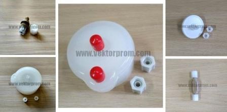 |
 |
| Чернила IC270BK | Растворитель MC270BK | Фильтры для принтера Domino | ЗАПЧАСТИ |
Расходные материалы для маркираторов


от 227 000 руб.
Устройство Domino А-120 предназначено для нанесения маркировки на практически любую поверхность ПЭТ-бутылки. В зависимости от требований производства и потребительских стандартов информация может оперативно изменяться.
Самые распространенные виды маркировки – время и дата выпуска, конечный срок реализации, номер продукта и номер партии.Также возможны такие варианты маркировки как нанесение логотипов на упаковку или нанесение многострочной маркировки, фактически заменяющей этикетку.
Предлагаемая модель Domino характеризуется высокой надежностью, удовлетворяют стандарту защиты IP 53, изготовлена из нержавеющей стали (304) и обеспечивает печать превосходного качества. Высокая надежность. Запатентованная печатающая головка с системой автоматической промывки обеспечивает надежные запуски даже после длительных периодов остановки принтера. Сменная картриджная система. Минимальные временные затраты на обслуживание.
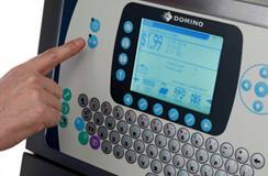
Упрощенная система вкл./выкл. принтера: нажатием одной кнопки подключается питание, настраивается струя и принтер готовится к печати, а при выключении принтера автоматически, производится его промывка, что обеспечивает его готовность к следующему включению.
Преимуществами данного оборудования является быстрота пуско-наладки, простота и удобство в эксплуатации и обслуживании, а также низкое потребление расходных материалов (чернил, разбавителя), которые поставляются в запечатанных картриджах и их замена является быстрой и чистой процедурой.
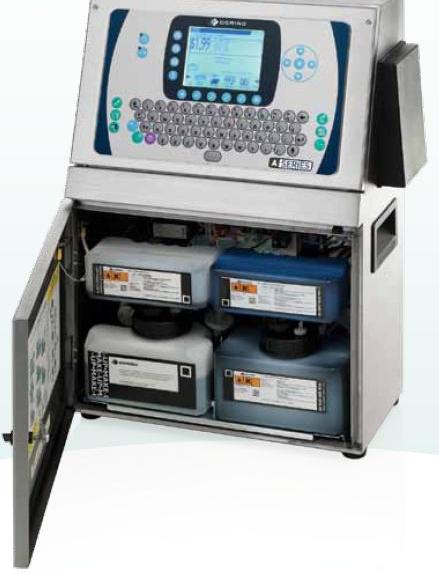
Мы предлагаем чернила, специально подобранные по химическому составу и обеспечивающие наилучшие адгезию и качество печати на различных поверхностях.
Достоинства Domino A-120:
Самая надежная система промывки – за счет электромагнитного клапана в форсунке. Пуск/выключение осуществляется с помощью одной кнопки. При этом происходит автопромывка всей чернильной системы.
Пока печатающая головка не работает, клапан форсунки закрыт, что гарантирует чистое и надежное начало работы. Это позволяет принтеру находиться в нерабочем состоянии в течение длительных периодов без специальной промывки.

ВИДЕО ПРИНЦИП РАБОТЫ ПРИНТЕРА
Примеры маркировки:
Техническте характеристики:
Domino A 120 Domino A 220
Автоматическая промывка (при включении и выключении)
Скорость печати до 147 метров в минуту Скорость печати до 325 метров в минуту
Печать в одну-три (1-3) строки Печать в одну-пять (1-5) строк
Высота символов от 3 до 12 мм Высота символов от 3 до 20 мм
Печатающая головка с кондуитом длиной 3 метра
Гидравлический принцип создания давления в чернильной системе
Стандарт защиты IP 53
Диапазон температур 5-45oC
Работа в условиях 10-90% относительной влажности
Не требуется внешний сжатый воздух
Руководство на русском языке
Для оформления Вашего запроса, просьба открыть форму «Оформить заказ», или связаться с нами по телефону или электронной почте.
Устройство Domino А-120 предназначено для нанесения маркировки на практически любую поверхность ПЭТ-бутылки. В зависимости от требований производства и потребительских стандартов информация может оперативно изменяться.
Самые распространенные виды маркировки – время и дата выпуска, конечный срок реализации, номер продукта и номер партии.Также возможны такие варианты маркировки как нанесение логотипов на упаковку или нанесение многострочной маркировки, фактически заменяющей этикетку.
Предлагаемая модель Domino характеризуется высокой надежностью, удовлетворяют стандарту защиты IP 53, изготовлена из нержавеющей стали (304) и обеспечивает печать превосходного качества. Высокая надежность. Запатентованная печатающая головка с системой автоматической промывки обеспечивает надежные запуски даже после длительных периодов остановки принтера. Сменная картриджная система. Минимальные временные затраты на обслуживание.
Упрощенная система вкл./выкл. принтера: нажатием одной кнопки подключается питание, настраивается струя и принтер готовится к печати, а при выключении принтера автоматически, производится его промывка, что обеспечивает его готовность к следующему включению.
Преимуществами данного оборудования является быстрота пуско-наладки, простота и удобство в эксплуатации и обслуживании, а также низкое потребление расходных материалов (чернил, разбавителя), которые поставляются в запечатанных картриджах и их замена является быстрой и чистой процедурой.
Мы предлагаем чернила, специально подобранные по химическому составу и обеспечивающие наилучшие адгезию и качество печати на различных поверхностях.
Достоинства Domino A-120:
Самая надежная система промывки – за счет электромагнитного клапана в форсунке. Пуск/выключение осуществляется с помощью одной кнопки. При этом происходит автопромывка всей чернильной системы.
Пока печатающая головка не работает, клапан форсунки закрыт, что гарантирует чистое и надежное начало работы. Это позволяет принтеру находиться в нерабочем состоянии в течение длительных периодов без специальной промывки.
Технические характеристики:
Domino A 120
Автоматическая промывка (при включении и выключении)
Скорость печати до 147 метров в минуту
Печать в одну-три (1-3) строки
Высота символов от 3 до 12 мм
Печатающая головка с кондуитом длиной 3 метра
Гидравлический принцип создания давления в чернильной системе
Стандарт защиты IP 53
Диапазон температур 5-45oC
Работа в условиях 10-90% относительной влажности
Не требуется внешний сжатый воздух
Руководство на русском языке
Назад в раздел