Click the link above to view the complete
manual. The file size for the complete manual is 7.65 MB. Individual chapters
and appendices may be downloaded below.
-
Page 1
DL05/06 Option Modules USER MANUAL Manual Number: D0-OPTIONS-M… -
Page 2
Copyright 2018, AutomationDirect.com Incorporated All Rights Reserved No part of this manual shall be copied, reproduced, or transmitted in any way without the prior, written consent of AutomationDirect.com Incorporated. AutomationDirect retains the exclusive rights to all information included in this document. -
Page 3
Esta publicación puede contener referencias a productos producidos y/u ofrecidos por otras compañías. Los nombres de las compañías y productos pueden tener marcas registradas y son propiedad única de sus respectivos dueños. Automationdirect.com, renuncia cualquier interés propietario en las marcas y nombres de otros. -
Page 4
Nulle partie de ce manuel ne doit être copiée, reproduite ou transmise de quelque façon que ce soit sans le consentement préalable écrit de la société Automationdirect.com Incorporated. AutomationDirect conserve les droits exclusifs à l’égard de tous les renseignements contenus dans le présent document. -
Page 5
01/02 Added new chapter and minor changes to chapters 3rd edition 05/02 Added wiring guidelines and new discrete module 4th edition 07/02 Added DL06 micro PLC information 4th edition 02/03 Minor changes and corrections Rev. A 5th edition 05/03 Added new chapter… -
Page 6: Table Of Contents
Conventions Used …………………. 1–2 Key Topics for Each Chapter ………………1–2 Selecting the Proper Module ………………1–3 DL05 ……………………1–3 DL06 ……………………1–3 Module Choices ………………….. 1–3 Module Choices, continued………………1–4 Installing the Option Modules ……………… 1–5 Remove the Slot Cover ………………… 1–5 Insert the Module …………………
-
Page 7
Table of Contents Emergency Power Disconnect ……………… 2–4 Orderly System Shutdown ………………2–4 Class 1, Division 2 Approval (Applies ONLY to modules used with a DL06 PLC.) ..2–4 System Wiring Strategies ………………2–5 PLC Isolation Boundaries ………………2–5 I/O “Common” Terminal Concepts …………….2–8 Connecting DC I/O to Solid State Field Devices ………… -
Page 8
DL05 Data Formatting ………………… 3–7 Structure of V7700 ………………..3–7 Structure of V7701 ………………..3–7 DL06 Data Formatting ………………… 3–8 Setup Data Type and Number of Channels ………….. 3–8 Storage Pointer Setup ………………..3–8 Using the Pointer in Your Control Program …………. 3–9 DL05 Pointer Method ……………….. -
Page 9
DL05 Pointer Method Using the IBox Instruction Available in DirectSOFT5 ….4–9 DL06 Pointer Method Using Conventional Ladder Logic ……..4–10 DL06 Pointer Method Using the IBox Instruction Available in DirectSOFT6 …. 4–11 DL05/06 Option Modules User Manual; 7th Ed. Rev. C… -
Page 10
Resolution Details ………………..4–14 Analog Input Ladder Logic Filter …………….4–15 PID Loops / Filtering ………………..4–15 Smoothing the Input Signal (DL06 only) …………..4–15 Binary Data Format Filter Using Ladder Logic …………4–15 BCD Data Format Filter Using Ladder Logic…………4–16 Example Code to Scale a 4–20 mA Signal to 0–1000 BCD …….. -
Page 11
Resolution Details ………………..5–14 Analog Input Ladder Logic Filter …………….5–15 PID Loops / Filtering: ………………..5–15 Smoothing the Input Signal (DL06 only): …………… 5–15 Using Binary Data Format………………5–15 Using BCD Data Format ………………5–16 Chapter 6 — F0-08ADH-2, 8-Channel Analog Voltage Input Module Specifications ……………….. -
Page 12
DL05 Pointer Method Using the IBox Instruction Available in DirectSOFT5 …. 6–10 DL06 Pointer Method Using Conventional Ladder Logic ……..6–11 DL06 Pointer Method Using the IBox Instruction Available in DirectSOFT5 …. 6–12 Scale Conversions ………………..6–12 Scaling the Input Data ………………. 6–12 The Conversion Program in Standard Ladder Logic ………. -
Page 13
DL05 Pointer Method Using the IBox Instruction Available in DirectSOFT5 ….7–9 DL06 Pointer Method Using Conventional Ladder Logic ……..7–10 DL06 Pointer Method Using the IBox Instruction Available in DirectSOFT5 …. 7–11 Output Scale Conversion ………………7–11 Calculating the Digital Output Value …………..7–11 The Conversion Program in Standard Ladder Logic ………. -
Page 14
DL05 Pointer Method Using the IBox Instruction Available in DirectSOFT6 ….9–9 DL06 Pointer Method Using Conventional Ladder Logic ……..9–10 DL06 Pointer Method Using the IBox Instruction Available in DirectSOFT6 …. 9–11 Output Scale Conversion ………………9–11 Calculating the Digital Output Value …………..9–11 The Conversion Program in Standard Ladder Logic ………. -
Page 15
DL05 Pointer Method Using the IBox Instruction Available in DirectSOFT6 …. 10–9 DL06 Pointer Method Using Conventional Ladder Logic ……..10–10 DL06 Pointer Method Using the IBox Instruction Available in DirectSOFT6 ..10–11 Output Scale Conversion ………………10–11 Calculating the Digital Output Value …………..10–11 The Conversion Program in Standard Ladder Logic ………. -
Page 16
Structure of V7700 ………………..11–8 Structure of V7701 ………………..11–8 Structure of V7702 ………………..11–9 DL06 Data Formatting ………………11–10 Setup Data Type and Number of Channels …………11–10 Input Storage Pointer Setup …………….. 11–10 Output Storage Pointer Setup …………….11–10 Using the Pointer in Your Control Program ………… -
Page 17
Resolution Details ………………..11–18 Analog Input Ladder Logic Filter …………….11–19 PID Loops / Filtering ………………… 11–19 Smoothing the Input Signal (DL06 only) ………….. 11–19 Using Binary Data Format………………11–19 Using BCD Data Format ………………11–20 Chapter 12 — F0-2AD2DA-2, 2-Channel In/2-Ch. Out Analog Voltage Combination Module Specifications ………………… -
Page 18
Analog Data Bits ………………..12–15 Analog Input Ladder Logic Filter …………….12–16 PID Loops / Filtering ………………… 12–16 Smoothing the Input Signal (DL06 only) ………….. 12–16 Using Binary Data Format………………12–16 Using BCD Data Format ………………12–17 Chapter 13 — F0-4AD2DA-2, 4-Channel In/2-Ch. Out Analog Voltage Combination Module Specifications ………………… -
Page 19
Resolution Details ………………..13–15 Analog Input Ladder Logic Filter …………….13–16 PID Loops / Filtering ………………… 13–16 Smoothing the Input Signal (DL06 only) ………….. 13–16 Using Binary Data Format………………13–16 Using BCD Data Format ………………13–17 Chapter 14 — F0-04RTD, 4-Channel RTC Input Module Specifications ………………… -
Page 20
Negative Temperatures 2’s Complement (Binary/Pointer Method) ……. 14–17 Analog Input Ladder Logic Filter …………….14–18 PID Loops / Filtering ………………… 14–18 Smoothing the Input Signal (DL06 only) ………….. 14–18 Using Binary Data Format………………14–18 Using BCD Data Format ………………14–19 RTD Burnout Detection Bits ……………… -
Page 21
Module Resolution 15-Bit Plus Sign (Bipolar Voltage Input) ……..15–18 Analog Input Ladder Logic Filter …………….15–19 PID Loops / Filtering ………………… 15–19 Smoothing the Input Signal (DL06 only) ………….. 15–19 Using Binary Data Format………………15–19 Using BCD Data Format ………………15–20 Thermocouple Burnout Detection Bits ………….. -
Page 22
hapter hapter hapter ettinG tarted In This Chapter… Introduction ………………….. 1–2 Conventions Used …………………. 1–2 Selecting the Proper Module ………………1–3 Installing the Option Modules ……………… 1–5 Module LED Indicator ………………..1–6 Power Budgeting ………………….. 1–6… -
Page 23: Chapter 1: Getting Started
PLC families. It will show you how to select and install an option module for your PLC. Supplemental Manuals You will either need a copy of the DL05 User Manual (D0–USER–M) or the DL06 User Manual (D0–06USER–M) at hand when incorporating any one of the option modules in your PLC.
-
Page 24: Selecting The Proper Module
The DL05 Micro PLC only has one option slot to install an option module. The proper selection of a module is dependent on the control application. DL06 The DL06 Micro PLC has four option slots. The option modules can also be added according to the control application. Module Choices There are over thirty option modules available.
-
Page 25: Module Choices, Continued
Chapter 1: Getting Started Module Choices, continued. Analog Modules Part Number Description F0-04AD-1 4-Channel Analog Input, Current F0-04AD-2 4-Channel Analog Input, Voltage F0-08ADH-1 8-Channel High-Resolution Analog Input, Current F0-08ADH-2 8-Channel High-Resolution Analog Input, Voltage F0-04DAH-1 4-Channel High-Resolution Analog Output, Current F0-04DAH-2 4-Channel High-Resolution Analog Output, Voltage F0-08DAH-1…
-
Page 26: Installing The Option Modules
Chapter 1: Getting Started Installing the Option Modules Before installing the option module in the DL05 option slot or the DL06 option slots set the necessary jumpers and/or dip switches on the module. Refer to the chapter(s) that pertains to the module(s) being installed.
-
Page 27: Module Led Indicator
I/O module is functioning properly. Power Budgeting The DL06 has four option card slots. To determine whether the combination of cards you select will have sufficient power, you will need to perform a power budget calculation. Power supplied Power is supplied from two sources, the internal base unit power supply and, if required, an external supply (customer furnished).
-
Page 28
Chapter 1: Getting Started DL06 Base Unit Power Required DL06 Power Supplied by Base Units Part Number 5 VDC (mA) 24 VDC (mA) Part Number 5 VDC (mA) 24 VDC (mA) D0-06AA 800mA none <1500mA 300mA D0-06xx D0-06AR 900mA none <2000mA… -
Page 29
hapter hapter hapter iscrete uiDelines In This Chapter… Safety Guidelines ………………….. 2–2 System Wiring Strategies ………………2–5 I/O Addressing ………………….2–15 Discrete I/O General Specifications ……………. 2–17 Glossary of Specification Terms …………….2–18 F0-08SIM 8-Point Simulator Input Module …………. 2–19 D0-10ND3 10-Point DC Input Module ………….. -
Page 30: Chapter 2: Discrete I/O Guidelines
The protection provided by the equipment may be impaired if this equipment is used in a manner not specified in this manual. A listing of our international affiliates is available on our Web site: http://www.automationdirect.com WARNING: Providing a safe operating environment for personnel and equipment is your responsibility and should be your primary goal during system planning and installation.
-
Page 31: Three Levels Of Protection
Chapter 2: Discrete I/O Guidelines Three Levels of Protection The publications mentioned provide many ideas and requirements for system safety. At a minimum, you should follow these regulations. Also, you should use the following techniques, which provide three levels of system control. •…
-
Page 32: Emergency Power Disconnect
Retract Class 1, Division 2 Approval (Applies ONLY to modules used with a DL06 PLC.) This equipment is suitable for use in Class 1, Division 2, groups A, B, C and D or non- hazardous locations only.
-
Page 33: System Wiring Strategies
Chapter 2: Discrete I/O Guidelines System Wiring Strategies The DirectLOGIC Micro PLCs are very flexible and will work in many different wiring configurations. By studying this section before actual installation, you can probably find the best wiring strategy for your application . This will help to lower system cost, wiring errors, and avoid safety problems.
-
Page 34
Chapter 2: Discrete I/O Guidelines The following figures show the internal layout of the DL05 and DL06 PLCs, as viewed from the front panels. To Programming Device or Operator Interface DL05 2 Comm. Ports Main Optional Power I/O Circuits Supply… -
Page 35
Chapter 2: Discrete I/O Guidelines Sinking/Sourcing Concepts Before going further in our study of wiring strategies, we must have a solid understanding of “sinking” and “sourcing” concepts. Use of these terms occurs frequently in input or output circuit discussions. It is the goal of this section to make these concepts easy to understand, further ensuring your success in installation. -
Page 36: I/O «Common» Terminal Concepts
Chapter 2: Discrete I/O Guidelines I/O “Common” Terminal Concepts In order for a PLC I/O circuit to operate, current must enter at one terminal and exit at another. Field Main Path Device (I/O point) This means at least two terminals are associated Circuit with every I/O point.
-
Page 37: Connecting Dc I/O To Solid State Field Devices
The six outputs of the DL05 have the same electrical common, even though there are two common terminal screws. Not so with the DL06 which has four isolated commons. Finally, recall that the DC output circuit…
-
Page 38
Chapter 2: Discrete I/O Guidelines In the next example we connect a PLC DC output point to the sinking input of a field device. This is a bit tricky, because both the PLC output and field device input are sinking type. -
Page 39: Relay Output Guidelines
Chapter 2: Discrete I/O Guidelines Relay Output Guidelines Relay outputs are available for the DirectLOGIC PLCs. Relays are best for the following applications: • Loads that require higher currents than the solid-state outputs can deliver • Cost-sensitive applications • Some output channels need isolation from other outputs (such as when some loads require different voltages than other loads) Some applications in which NOT to use relays: •…
-
Page 40: Surge Suppression For Inductive Loads
Chapter 2: Discrete I/O Guidelines Surge Suppression For Inductive Loads Inductive load devices (devices with a coil) generate transient voltages when de-energized with a relay contact. When a relay contact is closed it “bounces”, which energizes and de-energizes the coil until the “bouncing” stops. The transient voltages generated are much larger in amplitude than the supply voltage, especially with a DC supply voltage.
-
Page 41: Prolonging Relay Contact Life
Chapter 2: Discrete I/O Guidelines Use the following table to help select a TVS or MOV suppressor for your application based on the inductive load voltage. Surge Suppressors Vendor / Catalog Type Inductive Load Voltage Part Number AutomationDirect 110/120 VAC ZL-TD8-120 24VDC ZL-TD8-24…
-
Page 42: Dc Input Wiring Methods
DC voltages from one load to another. • The DL06 has isolated commons for each group of four outputs. There are two DL06 models with output switches that are current-sinking only, and one that has sourcing output switches.
-
Page 43: I/O Addressing
The following table shows the number of I/O points per module when used in the DL05 PLC or the first slot of a DL06 PLC that has a discrete module installed. Discrete I/O addressing for a DL06 is automatic from slot 1 to slot 4 by default.
-
Page 44: All Discrete Modules Installed I/O Addressing Example
Chapter 2: Discrete I/O Guidelines All Discrete Modules Installed I/O Addressing Example: Slot 1 Slot 2 Slot 3 Slot 4 16pt Input 4pt Input 10pt Output 8pt Output AC ( L ) AC ( N ) 24V N.C. (discrete) 4pt Output (discrete) (discrete) OUTPUT: 6–240V…
-
Page 45: Discrete I/O General Specifications
The following is a list of general specifications for the discrete I/O option modules that are available for both the DL05 and DL06 PLCs. Also shown is information on the various removable connectors that are used for field wiring on the discrete I/O option modules along with reference to the ZIPLink connection system products that are available for the 16-point I/O modules.
-
Page 46: Glossary Of Specification Terms
Chapter 2: Discrete I/O Guidelines Glossary of Specification Terms Discrete Input One of the input connections to the PLC which converts an electrical signal from a field device to a binary status (OFF or ON), which is read by the internal CPU each PLC scan. Discrete Output One of the output connections from the PLC which converts an internal ladder program result (0 or 1) to turn ON or OFF an output switching device.
-
Page 47: F0-08Sim 8-Point Simulator Input Module
NOTE: The DL05 CPU’s discrete feature for the F0-08SIM module requires DirectSOFT32 Version 3.0c (or later) and firmware version 4.90 (or later). The DL06 requires DirectSOFT32 version V4.0, build 16 (or later) and firmware version 1.80 (or later). See our website for more information: www.
-
Page 48: D0-10Nd3 10-Point Dc Input Module
NOTE: The DL05 CPU’s discrete feature for this module requires DirectSOFT32 Version 3.0c (or later) and firmware version 4.10 (or later). The DL06 requires DirectSOFT32 version V4.0, build 16 (or later) and firmware version 1.00 (or later). See our website for more information: www.
-
Page 49: D0-10Nd3F 10-Point Dc Fast Input Module
NOTE: The DL05 CPU’s discrete feature for this module requires DirectSOFT32 Version 3.0c (or later) and firmware version 4.70 (or later). The DL06 requires DirectSOFT32 version V4.0, build 16 (or later) and firmware version 1.50 (or later). See our website for more information: www.automationdirect.
-
Page 50: D0-16Nd3 16-Point Dc Input Module
53.9(D) requires DirectSOFT32 Version 3.0c (or later) and Weight 20g (0.71 oz.) firmware version 4.10 (or later). The DL06 requires DirectSOFT32 version V4.0, build 16 (or later) and firmware version 1.00 (or later). See our website for Derating chart more information: www.automationdirect.com.
-
Page 51: F0-08Na-1 8-Point Ac Input Module
F0-08NA-1 NOTE: The DL05 CPU’s discrete feature for this module requires DirectSOFT32 Version 3.0c (or later) and firmware version 4.70 (or later). The DL06 requires DirectSOFT32 version V4.0, build 16 (or later) and firmware version 1.50 (or later). See our website for more information: www.automationdirect.com.
-
Page 52: D0-10Td1 10-Point Dc Output Module
NOTE: The DL05 CPU’s discrete feature for this module requires DirectSOFT32 Version 3.0c (or later) and firmware version 4.10 (or later). The DL06 requires DirectSOFT32 version V4.0, build 16 (or later) and firmware version 1.00 (or later). See our website for more information: www.automationdirect.com.
-
Page 53: D0-16Td1 16-Point Dc Output Module
NOTE: The DL05 CPU’s discrete feature for this module requires DirectSOFT32 Version 3.0c (or later) and firmware version 4.10 (or later). The DL06 requires DirectSOFT32 version V4.0, build 16 (or later) and firmware version 1.00 (or later). See our website for more information: www.automationdirect.com.
-
Page 54: D0-10Td2 10-Point Dc Output Module
NOTE: The DL05 CPU’s discrete feature for this module requires DirectSOFT32 Version 3.0c (or later) and firmware version 4.10 (or later). The DL06 requires DirectSOFT32 version V4.0, build 16 (or later) and firmware version 1.00 (or later). See our website for more information: www.automationdirect.com.
-
Page 55: D0-16Td2 16-Point Dc Output Module
NOTE: The DL05 CPU’s discrete feature for this module requires DirectSOFT32 Version 3.0c (or later) and firmware version 4.10 (or later). The DL06 requires DirectSOFT32 version V4.0, build 16 (or later) and firmware version 1.00 (or later). See our website for more information: www.automationdirect.com.
-
Page 56: D0-07Cdr 4-Point Dc Input, 3-Point Relay Output Module
NOTE: The DL05 CPU’s discrete feature for this module requires DirectSOFT32 Version 3.0c (or later) and firmware version 4.10 (or later). The DL06 requires DirectSOFT32 version V4.0, build 16 (or later) and firmware version 1.00 (or later). See our website for more information: www.automationdirect.com.
-
Page 57: D0-08Tr 8-Point Relay Output Module
NOTE: The DL05 CPU’s discrete feature for this module requires DirectSOFT32 Version 3.0c (or later) and firmware version 4.10 (or later). The DL06 requires DirectSOFT32 version V4.0, build 16 (or later) and firmware version 1.00 (or later). See our website for more information: www.automationdirect.com.
-
Page 58: D0-08Cdd1 4-Point Dc Input, 4-Point Dc Output Module
NOTE: The DL05 CPU’s discrete feature for this module requires DirectSOFT32 Version 3.0c (or later) and firmware version 4.10 (or later). The DL06 requires DirectSOFT32 version V4.0, build 16 (or later) and firmware version 1.00 (or later). See our website for more information: www.automationdirect.com.
-
Page 59: F0-04Trs 4-Point Relay Output Module
NOTE: The DL05 CPU’s discrete feature for this module requires DirectSOFT32 Version 3.0c (or later) and firmware version 4.70 (or later). The DL06 requires DirectSOFT32 version V4.0, build 16 (or later) and firmware version 1.50 (or later). See our website for more information: www.automationdirect.com.
-
Page 60
F0-04AD-1, hapter hapter hapter hAnnel nAlog urrent nput In This Chapter… Module Specifications ………………..3–2 Setting the Module Jumper ………………3–4 Connecting and Disconnecting the Field Wiring …………. 3–4 Wiring Diagram ………………….3–5 Module Operation ………………… 3–6 Special V-memory Locations ………………3–7 Using the Pointer in Your Control Program …………. -
Page 61: Chapter 3: F0-04Ad-1, 4-Channel Analog Current Input
NOTE: The DL05 CPU’s analog feature for this module requires DirectSOFT32 Version 3.0c (or later) and firmware version 2.10 (or later). The DL06 requires DirectSOFT32 version V4.0, build 16 (or later) and firmware version 1.00 (or later). See our website for more information: www.automationdirect.com.
-
Page 62
Chapter 3: F0-04AD-1, 4-Channel Analog Current Input The following tables provide the specifications for the F0–04AD–1 Analog Input Module. Review these specifications to make sure the module meets your application requirements. Input Specifications Number of Channels 4, single ended (one common) Input Range 0 to 20mA or 4 to 20mA current (jumper selectable) Resolution… -
Page 63: Setting The Module Jumper
Chapter 3: F0-04AD-1, 4-Channel Analog Current Input Setting the Module Jumper The position of jumper J3 determines the input signal level. You can choose between 4–20 mA and 0–20 mA. The module ships with the jumper not connecting the two pins. In this position, the expected input signal is 4–20 mA.
-
Page 64: Wiring Diagram
Chapter 3: F0-04AD-1, 4-Channel Analog Current Input Wiring Diagram Use the following diagram to connect the field wiring. If necessary, the F0–04AD–1 terminal block can be removed to make removal of the module possible without disturbing field wiring. Typical User Wiring Internal See NOTE 1 Module…
-
Page 65: Module Operation
Module Operation Channel Scanning Sequence The DL05 and DL06 will read all four channels of input data during each scan. Each CPU supports special V-memory locations that are used to manage the data transfer. This is discussed in more detail beginning in the section on “Special V-memory Locations”.
-
Page 66: Special V-Memory Locations
Chapter 3: F0-04AD-1, 4-Channel Analog Current Input Special V-memory Locations Formatting the Module Data The DL05 and DL06 PLCs have special V-memory locations assigned to their respective option slots. These V-memory locations allow you to: • Specify the data format (binary or BCD) •…
-
Page 67: Dl06 Data Formatting
Chapter 3: F0-04AD-1, 4-Channel Analog Current Input DL06 Data Formatting Special V-memory locations are assigned to the four option slots of the DL06 PLC. The table below shows these V-memory locations which can be used to setup the F0–04AD–1. Analog Input Module DL06 Special V-memory Locations Slot No.
-
Page 68: Using The Pointer In Your Control Program
Chapter 3: F0-04AD-1, 4-Channel Analog Current Input Using the Pointer in Your Control Program DL05 Pointer Method The DL05 CPU examines the pointer values (the memory locations identified in V7700 and V7701) on the first scan only. The example program below shows how to setup these locations. This rung can be placed anywhere in the ladder program or in the initial stage if you are using stage programming instructions.
-
Page 69: Dl06 Pointer Method
Use the special V-memory table below as a guide to setup the storage pointer in the following example for the DL06. Slot 1 is the left most option slot. The CPU will examine the pointer values at these locations only after a mode transition.
-
Page 70: Detecting Input Signal Loss
Chapter 3: F0-04AD-1, 4-Channel Analog Current Input Detecting Input Signal Loss Analog Signal Loss The F0–04AD–1 analog module can sense the loss of analog input signals in 4–20 mA loops. The Special Relays described on page 3–14 allow you to use this feature in your ladder program. For example, in the rung below SP610 is used to pull-in coil Y1, which would be used to open or close an external circuit.
-
Page 71: The Conversion Program
Chapter 3: F0-04AD-1, 4-Channel Analog Current Input The Conversion Program The following example shows how you would write the program to perform the engineering unit conversion. This example assumes you have BCD data loaded into the appropriate V-memory locations using instructions that apply for the model of CPU you are using. Note: this example uses SP1, which is always on.
-
Page 72: Special Relays
Chapter 3: F0-04AD-1, 4-Channel Analog Current Input Special Relays The list of other Special Relays associated with the DL05 and DL06 PLCs are contained in the DL05 User Manual and the DL06 User Manual. The following special relays are new and relate to the status of the F0–04AD–1 module or one of its input channels.
-
Page 73
Chapter 3: F0-04AD-1, 4-Channel Analog Current Input DL06 Special Relays (cont’d) SLOT 3 SP340 Chan 1 input type 0 = 0–20 mA 1 = 4–20 mA SP341 Chan 2 input type 0 = 0–20 mA 1 = 4–20 mA SP342 Chan 3 input type 0 = 0–20 mA… -
Page 74: Module Resolution
Chapter 3: F0-04AD-1, 4-Channel Analog Current Input Module Resolution Analog Data Bits The first twelve bits represent the analog data in binary format. Value Value 9 8 7 6 5 4 3 2 1 = data bits 1024 2048 Resolution Details Since the module has 12-bit resolution, the analog signal is converted into 4096 counts ranging from 0 — 4095 (2 ).
-
Page 75: Analog Input Ladder Logic Filter
Analog Input Ladder Logic Filter PID Loops / Filtering: Please refer to the “PID Loop Operation” chapter in the DL06 or DL05 User Manual for information on the built-in PV filter (DL05/06) and the ladder logic filter (DL06 only) shown below.
-
Page 76: Using Bcd Data Format
Chapter 3: F0-04AD-1, 4-Channel Analog Current Input NOTE: Be careful not to do a multiple number conversion on a value. For example, if you are using the pointer method in BCD format to get the analog value, it must be converted to binary (BIN) as shown below.
-
Page 77
F0-08ADH-1, hapter hapter hapter HAnnel nAlog urrent nput In This Chapter… Module Specifications ………………..4–2 Connecting and Disconnecting the Field Wiring …………. 4–4 Wiring Diagram ………………….4–5 Module Operation ………………… 4–6 Special V-memory Locations ………………4–7 Using the Pointer in Your Control Program …………. 4–9 Scale Conversions ……………….. -
Page 78: Chapter 4: F0-08Adh-1, 8-Channel Analog Current Input
NOTE: The DL05 CPU’s analog feature for this module requires DirectSOFT32 Version 3.0c (or later) and firmware version 5.20 (or later). The DL06 requires DirectSOFT32 version V4.0, build 16 (or later) and firmware version 2.30 (or later). See our website for more information: www.automationdirect.com.
-
Page 79
RFI, (145MHz, 440Mhz 5W @ 15cm); Worst case error during noise disturbance is 0.5% of full scale Agency Approvals UL508; UL60079-15 Zone 2 Module Location Any slot in a DL05 or DL06 System Field Wiring Removable Terminal Block Weight 49g (1.7 oz.) 4–3… -
Page 80: Connecting And Disconnecting The Field Wiring
Chapter 4: F0-08ADH-1, 8-Channel Analog Current Input Connecting and Disconnecting the Field Wiring WARNING: Before removing the analog module or the terminal block on the face of the module, disconnect power to the PLC and all field devices. Failure to disconnect power can result in damage to the PLC and/or field devices.
-
Page 81: Wiring Diagram
Chapter 4: F0-08ADH-1, 8-Channel Analog Current Input Wiring Diagram Use the following diagram to connect the field wiring. If necessary, the F0–08ADH–1 terminal block can be removed to make removal of the module possible without disturbing field wiring. Typical User Wiring Internal Module Circuitry CH1 ADC 2-wire 4–20mA…
-
Page 82: Module Operation
Module Operation Channel Scanning Sequence The DL05 and DL06 will read all eight channels of input data during each scan. Each CPU supports special V-memory locations that are used to manage the data transfer. This is discussed in more detail beginning in the section on “Special V-memory Locations”.
-
Page 83: Special V-Memory Locations
Chapter 4: F0-08ADH-1, 8-Channel Analog Current Input Special V-memory Locations Formatting the Analog Module Data The DL05 and DL06 PLCs have special V-memory locations assigned to their respective option slots. These V-memory locations allow you to: • Specify the data format (binary or BCD) •…
-
Page 84: Dl06 Data Formatting
Chapter 4: F0-08ADH-1, 8-Channel Analog Current Input DL06 Data Formatting Special V-memory locations are assigned to the four option slots of the DL06 PLC. The table below shows these V-memory locations which can be used to setup the F0–08ADH–1. Analog Input Module DL06 Special V-memory Locations Slot No.
-
Page 85: Using The Pointer In Your Control Program
Chapter 4: F0-08ADH-1, 8-Channel Analog Current Input Using the Pointer in Your Control Program DL05 Pointer Method Using Conventional Ladder Logic NOTE: The proper use of the DL05 pointer requires that the V-memory address be written to the special memory location on the first scan only. Use the SP0 bit as a permissive contact when using the code shown below.
-
Page 86: Dl06 Pointer Method Using Conventional Ladder Logic
The F0–08ADH–1 can be installed in any available DL06 option slot. The ladder diagram below shows how to set up these locations with the module installed in slot 1 of the DL06. Use the above table to determine the pointer values if locating the module in any of the other slot locations.
-
Page 87: Dl06 Pointer Method Using The Ibox Instruction Available In Directsoft6
Chapter 4: F0-08ADH-1, 8-Channel Analog Current Input DL06 Pointer Method Using the IBox Instruction Available in DirectSOFT6 The following logic accomplishes the same thing as the previous ladder example, but it uses the IBox instruction ANLGIN. Analog Input Module Pointer Setup…
-
Page 88: The Conversion Program In Standard Ladder Logic
Chapter 4: F0-08ADH-1, 8-Channel Analog Current Input The Conversion Program in Standard Ladder Logic The following example shows how you would write the program to perform the engineering unit conversion. This example assumes you have BCD data loaded into the appropriate V-memory locations using instructions that apply for the model of CPU you are using.
-
Page 89: Analog And Digital Value Conversions
Chapter 4: F0-08ADH-1, 8-Channel Analog Current Input Analog and Digital Value Conversions Sometimes it is useful to convert between the signal levels and the digital values. This is especially helpful during machine start-up or troubleshooting. The following table provides formulas to make this conversion easier. Range If you know the digital value If you know the analog signal level…
-
Page 90: Module Resolution
Chapter 4: F0-08ADH-1, 8-Channel Analog Current Input Module Resolution Analog Data Bits Two 16-bit words are reserved for the analog data whether you are using BCD or binary data formatting. The 16 bits in the low word represent the analog data in binary format. BCD Example V2001 V2000…
-
Page 91: Analog Input Ladder Logic Filter
Analog Input Ladder Logic Filter PID Loops / Filtering Please refer to the “PID Loop Operation” chapter in the DL06 or DL05 User Manual for information on the built-in PV filter (DL05/06) and the ladder logic filter (DL06 only) shown below.
-
Page 92: Bcd Data Format Filter Using Ladder Logic
Chapter 4: F0-08ADH-1, 8-Channel Analog Current Input NOTE: Be careful not to do a multiple number conversion on a value. For example, if you are using the pointer method in BCD format to get the analog value, it must be converted to binary (BIN) as shown below. If you are using the pointer method in Binary format, the conversion to binary (BIN) instruction is not needed.
-
Page 93: Example Code To Scale A 4-20 Ma Signal To 0-1000 Bcd
Chapter 4: F0-08ADH-1, 8-Channel Analog Current Input Example Code to Scale a 4–20 mA Signal to 0–1000 BCD (For applications where the field transmitter sends a 4–20 mA signal to the analog input card.) This example will scale the first input, a double word BCD value located at V2000 and V2001, as a 4–20 mA input signal from 0–1000.
-
Page 94: Example Code To Scale A 4-20 Ma Signal To 0-1000 Binary
Chapter 4: F0-08ADH-1, 8-Channel Analog Current Input Example Code to Scale a 4–20 mA Signal to 0–1000 Binary (For applications where the field transmitter sends a 4–20 mA signal to the analog input card.) This example will scale the first input, a binary/decimal value located at V2000 (the CPU reserves two words for each channel so V2000 and V2001 are reserved), as a 4–20 mA input signal from 0–1000.
-
Page 95
F0-04AD-2, hapter hapter hapter hAnnel nAlog oltAge nput In This Chapter… Module Specifications ………………..5–2 Setting the Module Jumpers ………………5–4 Connecting and Disconnecting the Field Wiring …………. 5–5 Wiring Diagram ………………….5–5 Module Operation ………………… 5–6 Special V-memory Locations ………………5–7 Using the Pointer in Your Control Program …………. -
Page 96: Chapter 5 — F0-04Ad-2, 4-Channel Analog Voltage Input
NOTE: The DL05 CPU’s analog feature for this module requires DirectSOFT32 Version 3.0c (or later) and firmware version 2.10 (or later). The DL06 requires DirectSOFT32 version V4.0, build 16 (or later) and firmware version 1.00 (or later). See our website for more information: www.automationdirect.com.
-
Page 97
Chapter 5: F0-04AD-2 4-Ch. Analog Voltage Input The following tables provide the specifications for the F0–04AD–2 Analog Input Module. Review these specifications to make sure the module meets your application requirements. Input Specifications Number of Channels 4, single ended (one common) Input Range 0 to 5VDC or 0 to 10VDC (jumper selectable) Resolution… -
Page 98: Setting The Module Jumpers
Chapter 5: F0-04AD-2 4-Ch. Analog Voltage Input Setting the Module Jumpers The position of the J2 jumpers determines the input signal levels. You can choose between 0–5 VDC or 0–10 VDC. The module ships with the jumpers installed connecting the pins. In this position, the input signal level is 0–5 VDC.
-
Page 99: Connecting And Disconnecting The Field Wiring
Chapter 5: F0-04AD-2 4-Ch. Analog Voltage Input Connecting and Disconnecting the Field Wiring Wiring Guidelines Your company may have guidelines for wiring and cable installation. If so, you should check those before you begin the installation. Here are some general things to consider: •…
-
Page 100: Module Operation
Module Operation Input Channel Update Sequence The DL05 and DL06 read four channels of input data during each scan. The CPU supports special V-memory locations that are used to manage the data transfer. This is discussed in more detail on the next page, “Special V-memory Locations”.
-
Page 101: Special V-Memory Locations
Chapter 5: F0-04AD-2 4-Ch. Analog Voltage Input Special V-memory Locations Formatting the Module Data The DL05 and DL06 PLCs have special V-memory locations assigned to their respective option slots. These V-memory locations allow you to: • Specify the data format (binary or BCD) •…
-
Page 102: Dl06 Data Formatting
Chapter 5: F0-04AD-2 4-Ch. Analog Voltage Input DL06 Data Formatting Special V-memory locations are assigned to the four option module slots of the DL06 PLC. The table below shows these V-memory locations which can be used for the F0–04AD–2. Analog Input Module DL06 Special V-memory Locations Slot No.
-
Page 103: Using The Pointer In Your Control Program
Chapter 5: F0-04AD-2 4-Ch. Analog Voltage Input Using the Pointer in Your Control Program DL05 Pointer Method The DL05 CPU examines the pointer values (the memory locations identified in V7700 and V7701) on the first scan only. The example program below shows how to setup these locations. This rung can be placed anywhere in the ladder program or in the initial stage if you are using stage programming instructions.
-
Page 104: Dl06 Pointer Method
Use the special V-memory table below as a guide to setup the pointer values in the following example for the DL06. Slot 1 is the left most option slot. The CPU will examine the pointer values at these locations only after a mode transition, first scan only.
-
Page 105: Scale Conversions
Chapter 5: F0-04AD-2 4-Ch. Analog Voltage Input Scale Conversions Scaling the Input Data Units = A H – L Many applications call for measurements in 4095 engineering units, which can be more meaningful than raw data. Convert to engineering units using H = High limit of the engineering the formula shown to the right.
-
Page 106: The Conversion Program
Chapter 5: F0-04AD-2 4-Ch. Analog Voltage Input The Conversion Program The following example shows how you would write the program to perform the engineering unit conversion from input data formats 0–4095. This example assumes the raw input data read at V2000 is in BCD format. Note: this example uses SP1, which is always on.
-
Page 107: Analog And Digital Value Conversions
Chapter 5: F0-04AD-2 4-Ch. Analog Voltage Input Analog and Digital Value Conversions Sometimes it is useful to convert between the signal levels and the digital values. This is especially helpful during machine startup or troubleshooting. The following table provides formulas to make this conversion easier. Range If you know the digital value If you know the analog signal level…
-
Page 108: Module Resolution
Chapter 5: F0-04AD-2 4-Ch. Analog Voltage Input Module Resolution Analog Data Bits The first twelve bits represent the analog data in binary format. Value Value 9 8 7 6 5 4 3 2 1 = data bits 1024 2048 Resolution Details Since the module has 12-bit resolution, the analog voltage signal is converted into 4096 counts ranging from 0–4095 (2 ).
-
Page 109: Analog Input Ladder Logic Filter
Analog Input Ladder Logic Filter PID Loops / Filtering: Please refer to the “PID Loop Operation” chapter in the DL06 or DL05 User Manual for information on the built-in PV filter (DL05/06) and the ladder logic filter (DL06 only) shown below.
-
Page 110: Using Bcd Data Format
Chapter 5: F0-04AD-2 4-Ch. Analog Voltage Input NOTE: Be careful not to do a multiple number conversion on a value. For example, if you are using the pointer method in BCD format to get the analog value, it must be converted to binary (BIN) as shown below. If you are using the pointer method in Binary format, the conversion to binary (BIN) instruction is not needed.
-
Page 111
F0-08ADH-2, hapter hapter hapter HAnnel nAlog oltAge nput In This Chapter… Module Specifications ………………..6–2 Setting the Module Jumpers ………………6–4 Connecting and Disconnecting the Field Wiring …………. 6–5 Wiring Diagram ………………….6–6 Module Operation ………………… 6–7 Special V-memory Locations ………………6–8 Using the Pointer in Your Control Program ………… -
Page 112: Chapter 6: F0-08Adh-2, 8-Channel Analog Voltage Input
NOTE: The DL05 CPU’s analog feature for this module requires DirectSOFT32 Version 3.0c (or later) and firmware version 5.20 (or later). The DL06 requires DirectSOFT32 version V4.0, build 16 (or later) and firmware version 2.30 (or later). See our website for more information: www.automationdirect.com.
-
Page 113
RFI, (145MHz, 440MHz 5W @ 15cm); Worst case error during noise disturbance is 0.5% of full scale Agency Approvals UL508; UL60079-15 Zone 2 Module Location Any slot in a DL05 or DL06 System Field Wiring Removable Terminal Block Weight 49g (1.7 oz.) 6–3… -
Page 114: Setting The Module Jumpers
Chapter 6: F0-08ADH-2, 8-Channel Analog Voltage Input Setting the Module Jumpers The position of the jumper determines the input signal voltage levels. You can choose between 0–5 VDC or 0–10 VDC. The 0–5V position is the default position. With the jumper connecting the J5 posts, an input signal level of 0–5 VDC is selected.
-
Page 115: Connecting And Disconnecting The Field Wiring
Chapter 6: F0-08ADH-2, 8-Channel Analog Voltage Input Connecting and Disconnecting the Field Wiring WARNING: Before removing the analog module or the terminal block on the face of the module, disconnect power to the PLC and all field devices. Failure to disconnect power can result in damage to the PLC and/or field devices.
-
Page 116: Wiring Diagram
Chapter 6: F0-08ADH-2, 8-Channel Analog Voltage Input Wiring Diagram Use the following diagram to connect the field wiring. If necessary, the F0–08ADH–2 terminal block can be removed to make removal of the module possible without disturbing field wiring. Typical User Wiring Internal Module Circuitry CH1 ADC 3-wire Voltage…
-
Page 117: Module Operation
Module Operation Channel Scanning Sequence The DL05 and DL06 will read all eight channels of input data during each scan. Each CPU supports special V-memory locations that are used to manage the data transfer. This is discussed in more detail beginning in the section on “Special V-memory Locations”.
-
Page 118: Special V-Memory Locations
Chapter 6: F0-08ADH-2, 8-Channel Analog Voltage Input Special V-memory Locations Formatting the Analog Module Data The DL05 and DL06 PLCs have special V-memory locations assigned to their respective option slots. These V-memory locations allow you to: • Specify the data format (binary or BCD) •…
-
Page 119: Dl06 Data Formatting
Chapter 6: F0-08ADH-2, 8-Channel Analog Voltage Input DL06 Data Formatting Special V-memory locations are assigned to the four option slots of the DL06 PLC. The table below shows these V-memory locations which can be used to setup the F0–08ADH–2. Analog Input Module DL06 Special V-memory Locations Slot No.
-
Page 120: Using The Pointer In Your Control Program
Chapter 6: F0-08ADH-2, 8-Channel Analog Voltage Input Using the Pointer in Your Control Program DL05 Pointer Method Using Conventional Ladder Logic NOTE: The proper use of the DL05 pointer requires that the V-memory address be written to the special memory location on the first scan only. Use the SP0 bit as a permissive contact when using the code shown below.
-
Page 121: Dl06 Pointer Method Using Conventional Ladder Logic
The F0–08ADH–2 can be installed in any available DL06 option slot. The ladder diagram below shows how to set up these locations with the module installed in slot 1 of the DL06. Use the above table to determine the pointer values if locating the module in any of the other slot locations.
-
Page 122: Dl06 Pointer Method Using The Ibox Instruction Available In Directsoft5
Chapter 6: F0-08ADH-2, 8-Channel Analog Voltage Input DL06 Pointer Method Using the IBox Instruction Available in DirectSOFT5 The following logic accomplishes the same thing as the previous ladder example, but it uses the IBox instruction ANLGIN. Analog Input Module Pointer Setup…
-
Page 123: The Conversion Program In Standard Ladder Logic
Chapter 6: F0-08ADH-2, 8-Channel Analog Voltage Input The Conversion Program in Standard Ladder Logic The following example shows how you would write the program to perform the engineering unit conversion. This example assumes you have BCD data loaded into the appropriate V-memory locations using instructions that apply for the model of CPU you are using.
-
Page 124: Analog And Digital Value Conversions
Chapter 6: F0-08ADH-2, 8-Channel Analog Voltage Input Analog and Digital Value Conversions Sometimes it is useful to convert between the signal levels and the digital values. This is especially helpful during machine start-up or troubleshooting. The following table provides formulas to make this conversion easier. Range If you know the digital value If you know the analog signal level…
-
Page 125: Module Resolution
Chapter 6: F0-08ADH-2, 8-Channel Analog Voltage Input Module Resolution Analog Data Bits Two 16-bit words are reserved for the analog data whether you are using BCD or binary data formatting. The 16 bits in the low word represent the analog data in binary format. BCD Example V2001 V2000…
-
Page 126: Analog Input Ladder Logic Filter
Analog Input Ladder Logic Filter PID Loops / Filtering Please refer to the “PID Loop Operation” chapter in the DL06 or DL05 User Manual for information on the built-in PV filter (DL05/06) and the ladder logic filter (DL06 only) shown below.
-
Page 127: Using Bcd Data Format
Chapter 6: F0-08ADH-2, 8-Channel Analog Voltage Input NOTE: Be careful not to do a multiple number conversion on a value. For example, if you are using the pointer method in BCD format to get the analog value, it must be converted to binary (BIN) as shown below. If you are using the pointer method in Binary format, the conversion to binary (BIN) instruction is not needed.
-
Page 128
F0-04DAH-1, hapter hapter HAnnel nAlog urrent utput In This Chapter… Module Specifications ………………..7–2 Connecting and Disconnecting the Field Wiring …………. 7–4 Wiring Diagram ………………….7–5 Module Operation ………………… 7–6 Special V-memory Locations ………………7–7 Using the Pointer in Your Control Program …………. 7–9 Output Scale Conversion ……………… -
Page 129: Chapter 7: F0-04Dah-1, 4-Channel Analog Current Output
NOTE: The DL05 CPU’s analog feature for this module requires DirectSOFT32 Version 3.0c (or later) and firmware version 5.20 (or later). The DL06 requires DirectSOFT32 version V4.0, build 16 (or later) and firmware version 2.30 (or later). See our website for more information: www.automationdirect.com.
-
Page 130
440Mhz 5W @ 15cm); Worst case error during noise disturbance is 0.5% of full scale Agency Approvals UL508; UL60079-15 Zone 2 Module Location Any slot in a DL05 or DL06 System Field Wiring Removable Terminal Block Weight 49g (1.7 oz.) 7–3… -
Page 131: Connecting And Disconnecting The Field Wiring
Chapter 7: F0-04DAH-1, 4-Channel Analog Current Output Connecting and Disconnecting the Field Wiring WARNING: Before removing the analog module or the terminal block on the face of the module, disconnect power to the PLC and all field devices. Failure to disconnect power can result in damage to the PLC and/or field devices.
-
Page 132: Wiring Diagram
Chapter 7: F0-04DAH-1, 4-Channel Analog Current Output Wiring Diagram Use the following diagram to connect the field wiring. If necessary, the F0–04DAH–1 terminal block can be removed to make removal of the module possible without disturbing field wiring. Typical User Wiring Internal Module Circuitry 4-20mA Output Ch.
-
Page 133: Module Operation
Module Operation Channel Scanning Sequence The DL05 and DL06 will write all four channels of output data during each scan. Each CPU supports special V-memory locations that are used to manage the data transfer. This is discussed in more detail beginning in the section on “Special V-memory Locations.”…
-
Page 134: Special V-Memory Locations
Chapter 7: F0-04DAH-1, 4-Channel Analog Current Output Special V-memory Locations Formatting the Analog Module Data The DL05 and DL06 PLCs have special V-memory locations assigned to their respective option slots. These V-memory locations allow you to: • Specify the data format (binary or BCD) •…
-
Page 135: Dl06 Data Formatting
Chapter 7: F0-04DAH-1, 4-Channel Analog Current Output DL06 Data Formatting Special V-memory locations are assigned to the four option slots of the DL06 PLC. The table below shows these V-memory locations which can be used to setup the F0–04DAH–1. Analog Output Module DL06 Special V-memory Locations Slot No.
-
Page 136: Using The Pointer In Your Control Program
Chapter 7: F0-04DAH-1, 4-Channel Analog Current Output Using the Pointer in Your Control Program DL05 Pointer Method Using Conventional Ladder Logic NOTE: The proper use of the DL05 pointer requires that the V-memory address be written to the special memory location on the first scan only. Use the SP0 bit as a permissive contact when using the code shown below.
-
Page 137: Dl06 Pointer Method Using Conventional Ladder Logic
DL06 Pointer Method Using Conventional Ladder Logic NOTE: The proper use of the DL06 pointer requires that the V-memory address be written to the special memory location on the first scan only. Use the SP0 bit as a permissive contact when using the code shown below.
-
Page 138: Dl06 Pointer Method Using The Ibox Instruction Available In Directsoft5
Chapter 7: F0-04DAH-1, 4-Channel Analog Current Output DL06 Pointer Method Using the IBox Instruction Available in DirectSOFT5 The following logic accomplishes the same thing as the previous ladder example, but it uses the IBox instruction ANLGOUT. Analog Output Module Pointer Setup…
-
Page 139: The Conversion Program In Standard Ladder Logic
Chapter 7: F0-04DAH-1, 4-Channel Analog Current Output The Conversion Program in Standard Ladder Logic The following example shows how you would write the program to perform the engineering unit conversion. This example assumes you have BCD data loaded into the appropriate V-memory locations using instructions that apply for the model of CPU you are using.
-
Page 140: Analog And Digital Value Conversions
Chapter 7: F0-04DAH-1, 4-Channel Analog Current Output Analog and Digital Value Conversions Sometimes it is useful to convert between the signal levels and the digital values. This is especially helpful during machine startup or troubleshooting. The following table provides formulas to make this conversion easier. The formulas in the table show the relationship between A, the analog value, and D, the digital value.
-
Page 141: Module Resolution
Chapter 7: F0-04DAH-1, 4-Channel Analog Current Output Module Resolution Analog Data Bits Two 16-bit words are reserved for the analog data whether you are using BCD or binary data formatting. The 16 bits in the low word represent the analog data in binary format. BCD Example V2001 V2000…
-
Page 142
F0-08DAH-1, hapter hapter hapter HAnnel nAlog urrent utput In This Chapter… Module Specifications ………………..8–2 Connecting and Disconnecting the Field Wiring …………. 8–4 Wiring Diagram ………………….8–5 Module Operation ………………… 8–6 Special System V-memory Locations …………….. 8–7 Using the Pointer in Your Control Program …………. 8–9 Output Scale Conversion ……………… -
Page 143: Chapter 8: F0-08Dah-1, 8-Channel Analog Current Output
NOTE: The DL05 CPU’s analog feature for this module requires DirectSOFT32 Version 3.0c (or later) and firmware version 5.20 (or later). The DL06 requires DirectSOFT32 version V4.0, build 16 (or later) and firmware version 2.30 (or later). See our website for more information: www.automationdirect.com.
-
Page 144
RFI, (145MHz, 440Mhz 5W @ 15cm); Worst case error during noise disturbance is 0.5% of full scale Agency Approvals UL508; UL60079-15 Zone 2 Module Location Any slot in a DL05 or DL06 System Field Wiring Removable Terminal Block Weight 49g (1.7 oz.) 8–3… -
Page 145: Connecting And Disconnecting The Field Wiring
Chapter 8: F0-08DAH-1, 8-Channel Analog Current Output Connecting and Disconnecting the Field Wiring WARNING: Before removing the analog module or the terminal block on the face of the module, disconnect power to the PLC and all field devices. Failure to disconnect power can result in damage to the PLC and/or field devices.
-
Page 146: Wiring Diagram
Chapter 8: F0-08DAH-1, 8-Channel Analog Current Output Wiring Diagram Use the following diagram to connect the field wiring. If necessary, the F0–08DAH–1 terminal block can be removed to make removal of the module possible without disturbing field wiring. Typical User Wiring Internal Module Circuitry 4-20mA Output Ch.
-
Page 147: Module Operation
Module Operation Channel Scanning Sequence The DL05 and DL06 will read all eight channels of output data during each scan. Each CPU supports special V-memory locations that are used to manage the data transfer. This is discussed in more detail beginning in the section on “Special V-memory Locations”.
-
Page 148: Special System V-Memory Locations
Chapter 8: F0-08DAH-1, 8-Channel Analog Current Output Special System V-memory Locations Formatting the Analog Module Data The DL05 and DL06 PLCs have system V-memory locations assigned to their respective option slots. These V-memory locations allow you to: • Specify the data format (binary or BCD) •…
-
Page 149: Dl06 Data Formatting
Chapter 8: F0-08DAH-1, 8-Channel Analog Current Output DL06 Data Formatting Special V-memory locations are assigned to the four option slots of the DL06 PLC. The table below shows these V-memory locations which can be used to setup the F0–08DAH–1. Analog Output Module DL06 Special V-memory Locations Slot No.
-
Page 150: Using The Pointer In Your Control Program
Chapter 8: F0-08DAH-1, 8-Channel Analog Current Output Using the Pointer in Your Control Program DL05 Pointer Method Using Conventional Ladder Logic NOTE: The proper use of the DL05 pointer requires that the V-memory address be written to the special memory location on the first scan only. Use the SP0 bit as a permissive contact when using the code shown below.
-
Page 151: Dl06 Pointer Method Using Conventional Ladder Logic
DL06 Pointer Method Using Conventional Ladder Logic NOTE: The proper use of the DL06 pointer requires that the V-memory address be written to the special memory location on the first scan only. Use the SP0 bit as a permissive contact when using the code shown below.
-
Page 152: Dl06 Pointer Method Using The Ibox Instruction Available In Directsoft5
Chapter 8: F0-08DAH-1, 8-Channel Analog Current Output DL06 Pointer Method Using the IBox Instruction Available in DirectSOFT5 The following logic accomplishes the same thing as the previous ladder example, but it uses the IBox instruction ANLGOUT. Analog Output Module Pointer Setup…
-
Page 153: The Conversion Program In Standard Ladder Logic
Chapter 8: F0-08DAH-1, 8-Channel Analog Current Output The Conversion Program in Standard Ladder Logic The following example shows how you would write the program to perform the engineering unit conversion. This example assumes you have BCD data loaded into the appropriate V-memory locations using instructions that apply for the model of CPU you are using.
-
Page 154: Analog And Digital Value Conversions
Chapter 8: F0-08DAH-1, 8-Channel Analog Current Output Analog and Digital Value Conversions Sometimes it is useful to convert between the signal levels and the digital values. This is especially helpful during machine startup or troubleshooting. The following table provides formulas to make this conversion easier. The formulas in the table show the relationship between A, the analog value, and D, the digital value.
-
Page 155: Module Resolution
Chapter 8: F0-08DAH-1, 8-Channel Analog Current Output Module Resolution Analog Data Bits Two 16-bit words are reserved for the analog data whether you are using BCD or binary data formatting. The 16 bits in the low word represent the analog data in binary format. BCD Example V2001 V2000…
-
Page 156
F0-04DAH-2, hapter hapter hapter HAnnel nAlog oltAge utput In This Chapter… Module Specifications ………………..9–2 Connecting and Disconnecting the Field Wiring …………. 9–4 Wiring Diagram ………………….9–5 Module Operation ………………… 9–6 Special V-memory Locations ………………9–7 Using the Pointer in Your Control Program …………. 9–9 Output Scale Conversion ……………… -
Page 157: Chapter 9: F0-04Dah-2, 4-Channel Analog Voltage Output
NOTE: The DL05 CPU’s analog feature for this module requires DirectSOFT32 Version 3.0c (or later) and firmware version 5.20 (or later). The DL06 requires DirectSOFT32 version V4.0, build 16 (or later) and firmware version 2.30 (or later). See our website for more information: www.automationdirect.com.
-
Page 158
RFI, (145MHz, 440Mhz 5W @ 15cm); Worst case error during noise disturbance is 0.5% of full scale Agency Approvals UL508; UL60079-15 Zone 2 Module Location Any slot in a DL05 or DL06 System Field Wiring Removable Terminal Block Weight 49g (1.7 oz.) 9–3… -
Page 159: Connecting And Disconnecting The Field Wiring
Chapter 9: F0-04DAH-2, 4-Channel Analog Voltage Output Connecting and Disconnecting the Field Wiring WARNING: Before removing the analog module or the terminal block on the face of the module, disconnect power to the PLC and all field devices. Failure to disconnect power can result in damage to the PLC and/or field devices.
-
Page 160: Wiring Diagram
Chapter 9: F0-04DAH-2, 4-Channel Analog Voltage Output Wiring Diagram Use the following diagram to connect the field wiring. If necessary, the F0–04DAH–2 terminal block can be removed to make removal of the module possible without disturbing field wiring. Typical User Wiring Internal Module Circuitry Voltage Output Ch.
-
Page 161: Module Operation
Module Operation Channel Scanning Sequence The DL05 and DL06 will read all four channels of output data during each scan. Each CPU supports special V-memory locations that are used to manage the data transfer. This is discussed in more detail beginning in the section on “Special V-memory Locations”.
-
Page 162: Special V-Memory Locations
Chapter 9: F0-04DAH-2, 4-Channel Analog Voltage Output Special V-memory Locations Formatting the Analog Module Data The DL05 and DL06 PLCs have special V-memory locations assigned to their respective option slots. These V-memory locations allow you to: • Specify the data format (binary or BCD) •…
-
Page 163: Dl06 Data Formatting
Chapter 9: F0-04DAH-2, 4-Channel Analog Voltage Output DL06 Data Formatting Special V-memory locations are assigned to the four option slots of the DL06 PLC. The table below shows these V-memory locations which can be used to setup the F0–04DAH–2. Analog Output Module DL06 Special V-memory Locations Slot No.
-
Page 164: Using The Pointer In Your Control Program
Chapter 9: F0-04DAH-2, 4-Channel Analog Voltage Output Using the Pointer in Your Control Program DL05 Pointer Method Using Conventional Ladder Logic NOTE: The proper use of the DL05 pointer requires that the V-memory address be written to the special memory location on the first scan only. Use the SP0 bit as a permissive contact when using the code shown below.
-
Page 165: Dl06 Pointer Method Using Conventional Ladder Logic
DL06 Pointer Method Using Conventional Ladder Logic NOTE: The proper use of the DL06 pointer requires that the V-memory address be written to the special memory location on the first scan only. Use the SP0 bit as a permissive contact when using the code shown below.
-
Page 166: Dl06 Pointer Method Using The Ibox Instruction Available In Directsoft6
Chapter 9: F0-04DAH-2, 4-Channel Analog Voltage Output DL06 Pointer Method Using the IBox Instruction Available in DirectSOFT6 The following logic accomplishes the same thing as the previous ladder example, but it uses the IBox instruction ANLGOUT. Analog Output Module Pointer Setup…
-
Page 167: The Conversion Program In Standard Ladder Logic
Chapter 9: F0-04DAH-2, 4-Channel Analog Voltage Output The Conversion Program in Standard Ladder Logic The following example shows how you would write the program to perform the engineering unit conversion. This example assumes you have BCD data loaded into the appropriate V-memory locations using instructions that apply for the model of CPU you are using.
-
Page 168: Analog And Digital Value Conversions
Chapter 9: F0-04DAH-2, 4-Channel Analog Voltage Output Analog and Digital Value Conversions Sometimes it is useful to convert between the signal levels and the digital values. This is especially helpful during machine startup or troubleshooting. The following table provides formulas to make this conversion easier. The formulas in the table show the relationship between A, the analog value, and D, the digital value.
-
Page 169: Module Resolution
Chapter 9: F0-04DAH-2, 4-Channel Analog Voltage Output Module Resolution Analog Data Bits Two 16-bit words are reserved for the analog data whether you are using BCD or binary data formatting. The 16 bits in the low word represent the analog data in binary format. BCD Example V2001 V2000…
-
Page 170
F0-08DAH-2, hapter hapter hapter HAnnel nAlog oltAge utput In This Chapter… Module Specifications ………………… 10–2 Connecting and Disconnecting the Field Wiring ……….. 10–4 Wiring Diagram ………………….. 10–5 Module Operation ………………..10–6 Special V-memory Locations ………………. 10–7 Using the Pointer in Your Control Program …………10–9 Output Scale Conversion ……………… -
Page 171: Chapter 10: F0-08Dah-2, 8-Channel Analog Voltage Output
NOTE: The DL05 CPU’s analog feature for this module requires DirectSOFT32 Version 3.0c (or later) and firmware version 5.20 (or later). The DL06 requires DirectSOFT32 version V4.0, build 16 (or later) and firmware version 2.30 (or later). See our website for more information: www.automationdirect.com.
-
Page 172
RFI, (145MHz, 440MHz 5W @ 15cm); Worst case error during noise disturbance is 0.5% of full scale Agency Approvals UL508; UL60079-15 Zone 2 Module Location Any slot in a DL05 or DL06 System Field Wiring Removable Terminal Block Weight 49g (1.7 oz.) 10–3… -
Page 173: Connecting And Disconnecting The Field Wiring
Chapter 10: F0-08DAH-2, 8-Channel Analog Voltage Output Connecting and Disconnecting the Field Wiring WARNING: Before removing the analog module or the terminal block on the face of the module, disconnect power to the PLC and all field devices. Failure to disconnect power can result in damage to the PLC and/or field devices.
-
Page 174: Wiring Diagram
Chapter 10: F0-08DAH-2, 8-Channel Analog Voltage Output Wiring Diagram Use the following diagram to connect the field wiring. If necessary, the F0–08DAH–2 terminal block can be removed to make removal of the module possible without disturbing field wiring. Typical User Wiring Internal Module Circuitry Voltage Output Ch.
-
Page 175: Module Operation
Module Operation Channel Scanning Sequence The DL05 and DL06 will read all eight channels of output data during each scan. Each CPU supports special V-memory locations that are used to manage the data transfer. This is discussed in more detail beginning in the section on “Special V-memory Locations”.
-
Page 176: Special V-Memory Locations
Chapter 10: F0-08DAH-2, 8-Channel Analog Voltage Output Special V-memory Locations Formatting the Analog Module Data The DL05 and DL06 PLCs have special V-memory locations assigned to their respective option slots. These V-memory locations allow you to: • Specify the data format (binary or BCD) •…
-
Page 177: Dl06 Data Formatting
Chapter 10: F0-08DAH-2, 8-Channel Analog Voltage Output DL06 Data Formatting Special V-memory locations are assigned to the four option slots of the DL06 PLC. The table below shows these V-memory locations which can be used to setup the F0–08DAH–2. Analog Output Module DL06 Special V-memory Locations Slot No.
-
Page 178: Using The Pointer In Your Control Program
Chapter 10: F0-08DAH-2, 8-Channel Analog Voltage Output Using the Pointer in Your Control Program DL05 Pointer Method Using Conventional Ladder Logic NOTE: The proper use of the DL05 pointer requires that the V-memory address be written to the special memory location on the first scan only. Use the SP0 bit as a permissive contact when using the code shown below.
-
Page 179: Dl06 Pointer Method Using Conventional Ladder Logic
DL06 Pointer Method Using Conventional Ladder Logic NOTE: The proper use of the DL06 pointer requires that the V-memory address be written to the special memory location on the first scan only. Use the SP0 bit as a permissive contact when using the code shown below.
-
Page 180: Dl06 Pointer Method Using The Ibox Instruction Available In Directsoft6
Chapter 10: F0-08DAH-2, 8-Channel Analog Voltage Output DL06 Pointer Method Using the IBox Instruction Available in DirectSOFT6 The following logic accomplishes the same thing as the previous ladder example, but it uses the IBox instruction ANLGOUT. Analog Output Module Pointer Setup…
-
Page 181: The Conversion Program In Standard Ladder Logic
Chapter 10: F0-08DAH-2, 8-Channel Analog Voltage Output The Conversion Program in Standard Ladder Logic The following example shows how you would write the program to perform the engineering unit conversion. This example assumes you have BCD data loaded into the appropriate V-memory locations using instructions that apply for the model of CPU you are using.
-
Page 182: Analog And Digital Value Conversions
Chapter 10: F0-08DAH-2, 8-Channel Analog Voltage Output Analog and Digital Value Conversions Sometimes it is useful to convert between the signal levels and the digital values. This is especially helpful during machine startup or troubleshooting. The following table provides formulas to make this conversion easier. The formulas in the table show the relationship between A, the analog value, and D, the digital value.
-
Page 183: Module Resolution
Chapter 10: F0-08DAH-2, 8-Channel Analog Voltage Output Module Resolution Analog Data Bits Two 16-bit words are reserved for the analog data whether you are using BCD or binary data formatting. The 16 bits in the low word represent the analog data in binary format. BCD Example V2001 V2000…
-
Page 184
F0-4AD2DA-1, /2-C hAnnel hapter hapter hapter nAlOg urrent OmbInAtIOn In This Chapter… Module Specifications ………………… 11–2 Setting the Module Jumper ………………11–4 Connecting and Disconnecting the Field Wiring ……….. 11–5 Wiring Diagram ………………….. 11–6 Module Operation ………………..11–7 Special V-memory Locations ………………. 11–8 Using the Pointer in Your Control Program ………… -
Page 185: Module Specifications
NOTE: The DL05 CPU’s analog feature for this module requires DirectSOFT32 Version 3.0c (or later) and firmware version 3.30 (or later). The DL06 requires DirectSOFT32 version V4.0, build 16 (or later) and firmware version 1.00 (or later). See our website for more information: www.automationdirect.com.
-
Page 186
Chapter 11: F0-4AD2DA-1, 4-Ch. In/2-Ch. Out Analog Current Combination The following tables provide the specifications for the F0–4AD2DA–1 Analog Combination Module. Review these specifications to make sure the module meets your application requirements. Input Specifications Number of Channels 4, single ended (one common) Input Range 0 to 20mA or 4 to 20mA (jumper selectable) Resolution… -
Page 187: Setting The Module Jumper
Chapter 11: F0-4AD2DA-1, 4-Ch. In/2-Ch. Out Analog Current Combination General Specifications PLC Update Rate 4 input channels per scan, 2 output channels per scan 16-bit Data Word 12 binary data bits Operating Temperature 0 to 60°C (32 to 140°F) Storage Temperature -20 to 70°C (-4 to 158°F) Relative Humidity 5 to 95% (non-condensing)
-
Page 188: Connecting And Disconnecting The Field Wiring
Chapter 11: F0-4AD2DA-1, 4-Ch. In/2-Ch. Out Analog Current Combination Connecting and Disconnecting the Field Wiring Wiring Guidelines Your company may have guidelines for wiring and cable installation. If so, you should check those before you begin the installation. Here are some general things to consider: •…
-
Page 189: Wiring Diagram
Chapter 11: F0-4AD2DA-1, 4-Ch. In/2-Ch. Out Analog Current Combination Wiring Diagram Use the following diagram to connect the field wiring. If necessary, the terminal block can be removed to make removal of the module possible without disturbing field wiring. Typical User Wiring Internal See NOTE 1 Module…
-
Page 190: Module Operation
Module Operation Input/Output Channel Update Sequence The DL05 and DL06 will read four channels of input data and two channels of output data during each scan. Each CPU supports special V-memory locations that are used to manage the data transfer. This is discussed in more detail beginning on the next page, “Special V-memory Locations”.
-
Page 191: Special V-Memory Locations
Chapter 11: F0-4AD2DA-1, 4-Ch. In/2-Ch. Out Analog Current Combination Special V-memory Locations Formatting the Module Data The DL05 and DL06 PLCs have three special V-memory locations assigned to their respective option slots. These V-memory locations allow you to: • Specify the data format (binary or BCD) •…
-
Page 192: Structure Of V7702
Chapter 11: F0-4AD2DA-1, 4-Ch. In/2-Ch. Out Analog Current Combination Structure of V7702 V7702 is a system parameter that points to a V-memory location used for storing analog output data. The V-memory location loaded in V7702 is an octal number identifying the first V-memory location for the analog output data.
-
Page 193: Dl06 Data Formatting
Chapter 11: F0-4AD2DA-1, 4-Ch. In/2-Ch. Out Analog Current Combination DL06 Data Formatting Special V-memory locations are assigned to the four option module slots of the DL06 PLC. The table below shows these V-memory locations which can be used by the F0–4AD2DA–1.
-
Page 194: Using The Pointer In Your Control Program
Chapter 11: F0-4AD2DA-1, 4-Ch. In/2-Ch. Out Analog Current Combination Using the Pointer in Your Control Program DL05 Pointer Method The DL05 CPU examines the pointer values (the memory locations identified in V7700, V7701 and V7702) on the first scan only. The example program below shows how to setup these locations for 4 input channels and 2 output channels.
-
Page 195: Dl06 Pointer Method
Use the special V-memory table as a guide to setup the pointer values in the following example for the DL06. Slot 1 is the left most option slot. The CPU will examine the pointer values at these locations only after a mode transition, first scan only.
-
Page 196: Scale Conversions
Chapter 11: F0-4AD2DA-1, 4-Ch. In/2-Ch. Out Analog Current Combination Scale Conversions Scaling the Input Data Many applications call for measurements in Units = A H – L engineering units, which can be more meaningful 4095 than raw data. Convert to engineering units using H = High limit of the engineering the formula shown to the right.
-
Page 197: The Conversion Program
0–1000 in BCD format and stored them in V2300 and V2301 for channels 1 and 2 respectively. Both the DL05 and DL06 offer instructions that allow you to perform math operations using BCD format. It is usually easier to perform any math calculations in BCD and then convert the value to binary before you send the data to the module.
-
Page 198: Analog And Digital Value Conversions
Chapter 11: F0-4AD2DA-1, 4-Ch. In/2-Ch. Out Analog Current Combination Analog and Digital Value Conversions Sometimes it is useful to convert between the signal levels and the digital values. This is especially helpful during machine startup or troubleshooting. The following tables provide formulas to make this conversion easier.
-
Page 199: Special Relays
Chapter 11: F0-4AD2DA-1, 4-Ch. In/2-Ch. Out Analog Current Combination Special Relays The list of other Special Relays associated with the DL05 and DL06 PLCs are contained in the DL05 User Manual and the DL06 User Manual. The following special relays are new and relate to the status of the F0–04AD2DA–1 module or one of its input channels.
-
Page 200
Chapter 11: F0-4AD2DA-1, 4-Ch. In/2-Ch. Out Analog Current Combination DL06 Special Relays (cont’d) SLOT 3 SP340 Chan 1 input type 0 = 0–20 mA 1 = 4–20 mA SP341 Chan 2 input type 0 = 0–20 mA 1 = 4–20 mA… -
Page 201: Module Resolution
Chapter 11: F0-4AD2DA-1, 4-Ch. In/2-Ch. Out Analog Current Combination Module Resolution Analog Data Bits The first twelve bits represent the analog data in binary format. Value Value 9 8 7 6 5 4 3 2 1 = data bits 1024 2048 Resolution Details Since the module has 12-bit resolution, the analog signal is converted from 4096 counts…
-
Page 202: Analog Input Ladder Logic Filter
Analog Input Ladder Logic Filter PID Loops / Filtering Please refer to the “PID Loop Operation” chapter in the DL06 or DL05 User Manual for information on the built-in PV filter (DL05/06) and the ladder logic filter (DL06 only) shown below.
-
Page 203: Using Bcd Data Format
Chapter 11: F0-4AD2DA-1, 4-Ch. In/2-Ch. Out Analog Current Combination NOTE: Be careful not to do a multiple number conversion on a value. For example, if you are using the pointer method in BCD format to get the analog value, it must be converted to binary (BIN) as shown below. If you are using the pointer method in Binary format, the conversion to binary (BIN) instruction is not needed.
-
Page 204
F0-2AD2DA-2 2-C hapter hapter hapter /2-C nAlOg OltAge OmbInAtIOn In This Chapter… Module Specifications ………………… 12–2 Setting the Module Jumpers ………………. 12–4 Connecting and Disconnecting the Field Wiring ……….. 12–5 Wiring Diagram ………………….. 12–5 Module Operation ………………..12–6 Special V-memory Locations ………………. 12–7 Using the Pointer in Your Control Program ………… -
Page 205: Module Specifications
NOTE: The DL05 CPU’s analog feature for this module requires DirectSOFT32 Version 3.0c (or later) and firmware version 3.30 (or later). The DL06 requires DirectSOFT32 version V4.0, build 16 (or later) and firmware version 1.00 (or later). See our website for more information: www.automationdirect.com.
-
Page 206
Chapter 12: F0-2AD2DA-2 2-Ch. In/2-Ch. Out Analog Voltage Combination The following tables provide the specifications for the F0–2AD2DA–2 Analog Voltage Combination Module. Review these specifications to make sure the module meets your application requirements. Input Specifications Number of Channels 2, single ended (one common) Input Range 0 to 5VDC or 0 to 10VDC (jumper selectable) Resolution… -
Page 207: Setting The Module Jumpers
Chapter 12: F0-2AD2DA-2 2-Ch. In/2-Ch. Out Analog Voltage Combination General Specifications 2 input channels per scan PLC Update Rate 2 output channels per scan 16-bit Data Word 12 binary data bits Operating Temperature 0 to 60° C (32 to 140° F) Storage Temperature -20 to 70°…
-
Page 208: Connecting And Disconnecting The Field Wiring
Chapter 12: F0-2AD2DA-2 2-Ch. In/2-Ch. Out Analog Voltage Combination Connecting and Disconnecting the Field Wiring Wiring Guidelines Your company may have guidelines for wiring and cable installation. If so, you should check those before you begin the installation. Here are some general things to consider: •…
-
Page 209: Module Operation
Module Operation Input/Output Channel Scanning Sequence The DL05 and DL06 read two channels of input and two channels of output data during each scan. The CPU supports special V-memory locations that are used to manage the data transfer. This is discussed in more detail on the following page, “Special V-memory Locations”.
-
Page 210: Special V-Memory Locations
Chapter 12: F0-2AD2DA-2 2-Ch. In/2-Ch. Out Analog Voltage Combination Special V-memory Locations Formatting the Module Data The DL05 and DL06 PLCs have three special V-memory locations assigned to their respective option slots These V-memory locations allow you to: • Specify the data format (binary or BCD) •…
-
Page 211: Structure Of V7702
Chapter 12: F0-2AD2DA-2 2-Ch. In/2-Ch. Out Analog Voltage Combination Structure of V7702 V7702 is a system parameter that points to a V-memory location used for storing analog output data. The V-memory location loaded in V7702 is an octal number identifying the first V-memory location for the analog output data.
-
Page 212: Dl06 Data Formatting
Chapter 12: F0-2AD2DA-2 2-Ch. In/2-Ch. Out Analog Voltage Combination DL06 Data Formatting Special V-memory locations are assigned to the four option module slots of the DL06 PLC. The table below shows these V-memory locations which can be used by the F0–2AD2DA–2.
-
Page 213: Using The Pointer In Your Control Program
Chapter 12: F0-2AD2DA-2 2-Ch. In/2-Ch. Out Analog Voltage Combination Using the Pointer in Your Control Program DL05 Pointer Method The DL05 CPU examines the pointer values (the memory locations identified in V7700, V7701 and V7702) on the first scan only. The example program below shows how to setup these locations for 2 input channels and 2 output channels.
-
Page 214: Dl06 Pointer Method
Use the special V-memory table as a guide to setup the pointer values in the following example for the DL06. Slot 1 is the left most option slot. The CPU will examine the pointer values at these locations only after a mode transition, first scan only.
-
Page 215: Scale Conversions
Chapter 12: F0-2AD2DA-2 2-Ch. In/2-Ch. Out Analog Voltage Combination Scale Conversions Scaling the Input Data Many applications call for measurements in engineering units, which can be more meaningful Units = A H – L than raw data. Convert to engineering units using 4095 the formula shown to the right.
-
Page 216: The Conversion Program
0–1000 in BCD format and stored them in V2300 and V2301 for channels 1 and 2 respectively. Both the DL05 and DL06 offer instructions that allow you to perform math operations using BCD format. It is usually easier to perform any math calculations in BCD and then convert the value to binary before you send the data to the module.
-
Page 217: Analog And Digital Value Conversions
Chapter 12: F0-2AD2DA-2 2-Ch. In/2-Ch. Out Analog Voltage Combination Analog and Digital Value Conversions Sometimes it is useful to convert between the signal levels and the digital values. This is especially helpful during machine startup or troubleshooting. The following table provides formulas to make this conversion easier.
-
Page 218: Module Resolution
Chapter 12: F0-2AD2DA-2 2-Ch. In/2-Ch. Out Analog Voltage Combination Module Resolution Analog Data Bits The first twelve bits represent the analog data for both inputs and outputs in binary format. Value Value 9 8 7 6 5 4 3 2 1 = data bits 1024 2048…
-
Page 219: Analog Input Ladder Logic Filter
Analog Input Ladder Logic Filter PID Loops / Filtering Please refer to the “PID Loop Operation” chapter in the DL06 or DL05 User Manual for information on the built-in PV filter (DL05/06) and the ladder logic filter (DL06 only) shown below.
-
Page 220: Using Bcd Data Format
Chapter 12: F0-2AD2DA-2 2-Ch. In/2-Ch. Out Analog Voltage Combination NOTE: Be careful not to do a multiple number conversion on a value. For example, if you are using the pointer method in BCD format to get the analog value, it must be converted to binary (BIN) as shown below. If you are using the pointer method in Binary format, the conversion to binary (BIN) instruction is not needed.
-
Page 221
F0-4AD2DA-2, 4-C hapter hapter hapter /2-C nAlOg OltAge OmbInAtIOn In This Chapter… Module Specifications ………………… 13–2 Setting the Module Jumpers ………………. 13–4 Connecting and Disconnecting the Field Wiring ……….. 13–5 Wiring Diagram ………………….. 13–5 Module Operation ………………..13–6 Special V-memory Locations ………………. 13–7 Using the Pointer in Your Control Program ………… -
Page 222: Module Specifications
NOTE: The DL05 CPU’s analog feature for this module requires DirectSOFT32 Version 3.0c (or later) and firmware version 3.30 (or later). The DL06 requires DirectSOFT32 version V4.0, build 16 (or later) and firmware version 1.00 (or later). See our website for more information: www.automationdirect.com.
-
Page 223
Chapter 13: F0-4AD2DA-2, 4-Ch. In/2 Ch. Out Analog Voltage Combination The following tables provide the specifications for the F0–4AD2DA–2 Analog Combination Module. Review these specifications to make sure the module meets your application requirements. Input Specifications Number of Channels 4, single ended (one common) Input Range 0 to 5VDC or 0 to 10VDC (jumper selectable) Resolution… -
Page 224: Setting The Module Jumpers
Chapter 13: F0-4AD2DA-2, 4-Ch. In/2 Ch. Out Analog Voltage Combination General Specifications 4 input channels per scan PLC Update Rate 2 output channels per scan 16-bit Data Word 12 binary data bits Operating Temperature 0 to 60° C (32 to 140° F) Storage Temperature -20 to 70°…
-
Page 225: Connecting And Disconnecting The Field Wiring
Chapter 13: F0-4AD2DA-2, 4-Ch. In/2 Ch. Out Analog Voltage Combination Connecting and Disconnecting the Field Wiring Wiring Guidelines Your company may have guidelines for wiring and cable installation. If so, you should check those before you begin the installation. Here are some general things to consider: •…
-
Page 226: Module Operation
Module Operation Input/Output Channel Update Sequence The DL05 and DL06 read four channels of input data and two channels of output data during each scan. The CPU supports special V-memory locations that are used to manage the data transfer. This is discussed in more detail on the next page, “Special V-memory Locations”.
-
Page 227: Special V-Memory Locations
Chapter 13: F0-4AD2DA-2, 4-Ch. In/2 Ch. Out Analog Voltage Combination Special V-memory Locations Formatting the Module Data The DL05 and DL06 PLCs have three special V-memory locations assigned to their respective option slots. These V-memory locations allow you to: • Specify the data format (binary or BCD) •…
-
Page 228: Structure Of V7702
Chapter 13: F0-4AD2DA-2, 4-Ch. In/2 Ch. Out Analog Voltage Combination Structure of V7702 V7702 is a system parameter that points to a V-memory location used for storing analog output data. The V-memory location loaded in V7702 is an octal number identifying the first V-memory location for the analog output data.
-
Page 229: Dl06 Data Formatting
Chapter 13: F0-4AD2DA-2, 4-Ch. In/2 Ch. Out Analog Voltage Combination DL06 Data Formatting Special V-memory locations are assigned to the four option module slots of the DL06 PLC. The table below shows these V-memory locations which can be used for the F0–4AD2DA–2.
-
Page 230: Using The Pointer In Your Control Program
Chapter 13: F0-4AD2DA-2, 4-Ch. In/2 Ch. Out Analog Voltage Combination Using the Pointer in Your Control Program DL05 Pointer Method The DL05 CPU examines the pointer values (the memory locations identified in V7700, V7701 and V7702) on the first scan only. The example program below shows how to setup these locations for 4 input channels and 2 output channels.
-
Page 231: Dl06 Pointer Method
Use the special V-memory table as a guide to setup the pointer values in the following example for the DL06. Slot 1 is the left most option slot. The CPU will examine the pointer values at these locations only after a mode transition, first scan only.
-
Page 232: Scale Conversions
Chapter 13: F0-4AD2DA-2, 4-Ch. In/2 Ch. Out Analog Voltage Combination Scale Conversions Scaling the Input Data Many applications call for measurements in engineering Units = A H – L units, which can be more meaningful than raw data. 4095 Convert to engineering units using the formula shown to the right.
-
Page 233: The Conversion Program
0–1000 in BCD format and stored them in V2300 and V2301 for channels 1 and 2 respectively. The DL05 and DL06 offer instructions that allow you to perform math operations using BCD format. It is usually easier to perform any math calculations in BCD and then convert the value to binary before you send the data to the module.
-
Page 234: Analog And Digital Value Conversions
Chapter 13: F0-4AD2DA-2, 4-Ch. In/2 Ch. Out Analog Voltage Combination Analog and Digital Value Conversions Sometimes it is useful to convert between the signal levels and the digital values. This is especially helpful during machine startup or troubleshooting. The following table provides formulas to make this conversion easier.
-
Page 235: Module Resolution
Chapter 13: F0-4AD2DA-2, 4-Ch. In/2 Ch. Out Analog Voltage Combination Module Resolution Analog Data Bits The first twelve bits represent the analog data for both inputs and outputs in binary format. Value Value 9 8 7 6 5 4 3 2 1 = data bits 1024 2048…
-
Page 236: Analog Input Ladder Logic Filter
Analog Input Ladder Logic Filter PID Loops / Filtering Please refer to the “PID Loop Operation” chapter in the DL06 or DL05 User Manual for information on the built-in PV filter (DL05/06) and the ladder logic filter (DL06 only) shown below.
-
Page 237: Using Bcd Data Format
Chapter 13: F0-4AD2DA-2, 4-Ch. In/2 Ch. Out Analog Voltage Combination NOTE: Be careful not to do a multiple number conversion on a value. For example, if you are using the pointer method in BCD format to get the analog value, it must be converted to binary (BIN) as shown below. If you are using the pointer method in Binary format, the conversion to binary (BIN) instruction is not needed.
-
Page 238
hapter hapter hapter F0-04RTD, RTD I hannel npuT In This Chapter… Module Specifications ………………… 14–2 Connecting and Disconnecting the Field Wiring ……….. 14–4 Module Operation ………………..14–6 Special V-memory Locations ………………. 14–7 Configuring the Module in Your Control Program ……….14–11 Negative Temperature Readings with Magnitude Plus Sign ……. -
Page 239: Chapter 14 — F0-04Rtd, 4-Channel Rtc Input
NOTE: The DL05 CPU’s analog feature for this module requires DirectSOFT32 Version 3.0c (or later) and firmware version 4.70 (or later). The DL06 requires DirectSOFT32 version V4.0, build 16 (or later) and firmware version 1.50 (or later). See our website for more information: www.automationdirect.com.
-
Page 240: Module Calibration
Chapter 14: F0-04RTD 4-Channel RTD Input Module Calibration The module automatically re-calibrates every five seconds to remove any offset and gain errors. The F0-04RTD module requires no user calibration. However, if your process requires calibration, it is possible to correct the RTD tolerance using ladder logic. You can subtract or add a constant to the actual reading for that particular RTD.
-
Page 241: Connecting And Disconnecting The Field Wiring
Chapter 14: F0-04RTD 4-Channel RTD Input Connecting and Disconnecting the Field Wiring Wiring Guidelines Your company may have guidelines for wiring and cable installation. If so, you should check those before you begin the installation. Here are some general things to consider: •…
-
Page 242: Ambient Variations In Temperature
Chapter 14: F0-04RTD 4-Channel RTD Input Ambient Variations in Temperature The F0-04RTD module has been designed to operate within the ambient temperature range of 0°C to 60°C. Precision analog measurement with no long term temperature drift is assured by a chopper stabilized programmable gain amplifier, ratiometric referencing, and automatic offset and gain calibration.
-
Page 243: Module Operation
Module Operation Channel Scanning Sequence The DL05 and DL06 read all four input channels data during each scan. The CPUs support special V-memory locations that are used to manage the data transfer. This is discussed in more detail on the following page, “Special V-memory Locations”.
-
Page 244: A: Number Of Channels Enabled/Data Format Register
F: Diagnostic Error V7707 V707 V717 V727 V737 The table below shows the special V-memory locations used by the DL05 and DL06 PLCs for the F0–04RTD module. A: Number of Channels Enabled/Data Format Register Number of Channel Data in Channel Data in…
-
Page 245: B: Input Pointer Register
Registers table on the previous page. For example, if using a Pt1000 RTD with a module installed in slot 2 of a DL06, load a value of 4 into V713. All channels of the module must be the same RTD type.
-
Page 246: D: Units Code Register
Chapter 14: F0-04RTD 4-Channel RTD Input D: Units Code Register All RTD types are converted into a direct temperature reading in either Fahrenheit or Celsius. The data contains one implied decimal place. For example, a value in V-memory of 1002 would be 100.2 °C or °F.
-
Page 247: E: Rtd Burnout Data Value Register
Chapter 14: F0-04RTD 4-Channel RTD Input E: RTD Burnout Data Value Register This register is used to define either up scale or down scale channel values when a channel RTD burnout occurs. Bit 0 = Up scale/down scale value at Burnout 0 = Up scale value at Burnout, 7FFF (BCD/HEX) or 32767 (Binary) written to CH register…
-
Page 248: Configuring The Module In Your Control Program
Chapter 14: F0-04RTD 4-Channel RTD Input Configuring the Module in Your Control Program DL05 Example 1 The example program below shows how to setup the F0–04RTD for 4 input channels enabled, use of a type Pt100 RTD on all 4 input channels, BCD channel data format, the Fahrenheit (°F ) temperature scale, magnitude plus sign bit format, and an up scale burnout value specified.
-
Page 249: Dl05 Example 2
Chapter 14: F0-04RTD 4-Channel RTD Input DL05 Example 2 The example program below shows how to setup the F0–04RTD for 2 input channels enabled, use of a type Cu10 RTD on the first 2 input channels, BCD channel data format, Celsius (ºC) temperature scale, 2’s complement format, and with a down-scale burnout value specified.
-
Page 250: Dl06 Example 1
Chapter 14: F0-04RTD 4-Channel RTD Input DL06 Example 1 The example program below shows how to setup the F0–04RTD in option slot 1 for 4 input channels enabled, use of a type Pt100 RTD on all 4 input channels, BCD channel data format, Fahrenheit (ºF) temperature scale, magnitude plus sign bit format, and an up-scale burnout…
-
Page 251: Dl06 Example 2
Chapter 14: F0-04RTD 4-Channel RTD Input DL06 Example 2 The example program below shows how to setup the F0–04RTD in option slot 2 for 2 input channels enabled, use of a type Cu10 RTD on the first 2 input channels, BCD channel data format, Celsius (ºC ) temperature scale, 2’s complement format, and with a down scale burnout…
-
Page 252: Negative Temperature Readings With Magnitude Plus Sign
Chapter 14: F0-04RTD 4-Channel RTD Input Negative Temperature Readings with Magnitude Plus Sign With bipolar ranges, you need some additional logic to determine whether the value being returned represents a positive temperature or a negative temperature. There is a simple solution: •…
-
Page 253: Magnitude Plus Sign (Bcd)
Chapter 14: F0-04RTD 4-Channel RTD Input Magnitude Plus Sign (BCD) Check Channel 1 Load channel 1 data from V-memory into the accumulator. Remember, the data can be negative. V2000 Contact SP1 is always on. This instruction masks the sign bit of the BCD data, if it ANDD is set.
-
Page 254: Negative Temperatures 2’S Complement (Binary/Pointer Method)
Chapter 14: F0-04RTD 4-Channel RTD Input Negative Temperatures 2’s Complement (Binary/Pointer Method) You can use the 2’s complement mode for negative temperature display purposes, while at the same time using the magnitude plus sign of the temperature in your control program. The DirectSOFT32 element Signed Decimal is used to display negative numbers in 2’s complement form.
-
Page 255: Analog Input Ladder Logic Filter
Analog Input Ladder Logic Filter PID Loops / Filtering Please refer to the “PID Loop Operation” chapter in the DL06 or DL05 User Manual for information on the built-in PV filter (DL05/06) and the ladder logic filter (DL06 only) shown below.
-
Page 256: Using Bcd Data Format
Chapter 14: F0-04RTD 4-Channel RTD Input NOTE: Be careful not to do a multiple number conversion on a value. For example, if you are using the pointer method in BCD format to get the analog value, it must be converted to binary (BIN) as shown below. If you are using the pointer method in Binary format, the conversion to binary (BIN) instruction is not needed.
-
Page 257: Rtd Burnout Detection Bits
Special Relays Corresponding to RTD Burnouts The following Special Relay (SP) bits can be used in your program to monitor for RTD burnout. SP bit : 0 = RTD OK 1 = RTD burnout DL05 and DL06 Option Slot Module Channel DL05 DL06 DL06 DL06…
-
Page 258
hapter hapter hapter F0-04THM 4-C Hannel HerMoCouple npuT In This Chapter… Module Specifications ………………… 15–2 Connecting and Disconnecting the Field Wiring ……….. 15–4 Module Operation ………………..15–7 Special V-memory Locations ………………. 15–8 Configuring the Module in Your Control Program ……….15–12 Negative Temperature Readings with Magnitude Plus Sign ……. -
Page 259: Chapter 15: F0-04Thm 4-Channel Thermocouple Input
NOTE: The DL05 CPU’s analog feature for this module requires DirectSOFT32 Version 3.0c (or later) and firmware version 4.60 (or later). The DL06 requires DirectSOFT32 version V4.0, build 16 (or later) and firmware version 1.40 (or later). See our website for more information: www.automationdirect.com.
-
Page 260
Chapter 15: F0-04THM 4-Channel Thermocouple Input The following tables provide the specifications for the F0-04THM Analog Input Module. Review these specifications to make sure the module meets your application requirements. General Specifications Number of Channels 4, differential inputs, voltage or thermocouple Common Mode Range -1.3 VDC to +3.8 VDC Conversion Time… -
Page 261: Connecting And Disconnecting The Field Wiring
Chapter 15: F0-04THM 4-Channel Thermocouple Input Connecting and Disconnecting the Field Wiring Wiring Guidelines Your company may have guidelines for wiring and cable installation. If so, you should check those before you begin the installation. Here are some general things to consider: •…
-
Page 262: Thermocouples
Chapter 15: F0-04THM 4-Channel Thermocouple Input Thermocouples Use shielded thermocouples whenever possible to minimize the presence of noise on the thermocouple wire. Ground the shield wire at one end only. For both grounded and ungrounded thermocouples, connect the shield to the 0V (common) terminal of the PLC power supply. Grounded Thermocouple Assembly A grounded thermocouple provides better response time than an ungrounded thermocouple because the tip of the thermocouple junction is in direct contact with the protective case.
-
Page 263: Voltage Input Wiring Diagram
Chapter 15: F0-04THM 4-Channel Thermocouple Input Voltage Input Wiring Diagram All of the module’s CH– terminals must be connected together as shown below. This will help eliminate ground potential differences between the input channels that could cause damage to the module. The two unlabeled terminals are internally connected and may be used for convenience to connect the CH–…
-
Page 264: Module Operation
Module Operation Channel Scanning Sequence The DL05 and DL06 read the data from all four input channels during each scan. The CPUs support special V-memory locations that are used to manage the data transfer. This is discussed in more detail on the following page, “Special V-memory Locations”.
-
Page 265: Special V-Memory Locations
• Specify burnout data value at burnout • Read module setup diagnostics Module Configuration Registers The table below shows the special V-memory locations used by the DL05 and DL06 PLCs for the F0–04THM module. DL05 and DL06 Option Slot Module Configuration…
-
Page 266: B: Input Pointer Register
Chapter 15: F0-04THM 4-Channel Thermocouple Input B: Input Pointer Register This is a system parameter that points to a V-memory location used for storing module channel input data. The V-memory location loaded in the input pointer V-memory location is an octal number identifying the first V-memory location for the input data.
-
Page 267: D: Units Code Register
Chapter 15: F0-04THM 4-Channel Thermocouple Input D: Units Code Register All thermocouple types are converted into a direct temperature reading in either Fahrenheit or Celsius. The data contains one implied decimal place. For example, a value in V-memory of 1002 would be 100.2 °C or °F. For thermocouple ranges which include negative temperatures (J,E,K,T,N), the display resolution is from –3276.7 to +3276.7.
-
Page 268: E: Thermocouple Burnout Detection Enable Register
Chapter 15: F0-04THM 4-Channel Thermocouple Input E: Thermocouple Burnout Detection Enable Register This register is used to enable/disable the thermocouple burnout function. Be sure to disable the burnout detection function when checking the module calibration. Bit 0 = Thermocouple Burnout Detection Enable/Disable 0 = Burnout detection is enabled 1 = Burnout detection is disabled Burnout…
-
Page 269: Configuring The Module In Your Control Program
Chapter 15: F0-04THM 4-Channel Thermocouple Input Configuring the Module in Your Control Program DL05 Example 1 The example program below shows how to setup the F0–04THM for 4 input channels enabled, J type thermocouple on all 4 input channels, BCD channel data format, Fahrenheit (ºF) temperature scale, magnitude plus sign bit format, and burnout detection enabled with an up scale burnout specified.
-
Page 270: Dl05 Example 2
Chapter 15: F0-04THM 4-Channel Thermocouple Input DL05 Example 2 The example program below shows how to setup the F0–04THM for 2 input channels enabled, use of a K type thermocouple on the first 2 input channels, BCD channel data format, Celsius (ºC) temperature scale, 2’s complement format, and burnout detection enabled with a down scale burnout specified.
-
Page 271: Dl06 Example 1
Chapter 15: F0-04THM 4-Channel Thermocouple Input DL06 Example 1 The example program below shows how to setup the F0–04THM in option slot 1 for 4 input channels enabled, use of a J type thermocouple on all 4 input channels, BCD channel data format, Fahrenheit (ºF ) temperature scale and magnitude plus sign bit format, and burnout…
-
Page 272: Dl06 Example 2
Chapter 15: F0-04THM 4-Channel Thermocouple Input DL06 Example 2 The example program below shows how to setup the F0–04THM in option slot 2 for 2 input channels enabled, use of a K type thermocouple on the first 2 input channels, BCD channel data format, Celsius (ºC ) temperature scale, 2’s complement format, and burnout detection…
-
Page 273: Negative Temperature Readings With Magnitude Plus Sign
Chapter 15: F0-04THM 4-Channel Thermocouple Input Negative Temperature Readings with Magnitude Plus Sign With bipolar ranges, you need some additional logic to determine whether the value being returned represents a positive temperature/voltage or a negative temperature/voltage. There is a simple solution: •…
-
Page 274: Magnitude Plus Sign (Bcd)
Chapter 15: F0-04THM 4-Channel Thermocouple Input Magnitude Plus Sign (BCD) Check Channel 1 Load channel 1 data from V-memory into the accumulator. Remember, the data can be negative. V2000 Contact SP1 is always on. This instruction masks the sign bit of the BCD data, if it ANDD is set.
-
Page 275: Module Resolution
Chapter 15: F0-04THM 4-Channel Thermocouple Input Module Resolution Module Resolution 16-Bit (Unipolar Voltage Input) Unipolar analog signals are converted 156.25 into 65536 (2 ) counts ranging from mVDC 0 to 65535. For example, with a 0 to 156.25 mVDC signal range, 78 mVDC would be 32767.
-
Page 276: Analog Input Ladder Logic Filter
Analog Input Ladder Logic Filter PID Loops / Filtering Please refer to the “PID Loop Operation” chapter in the DL06 or DL05 User Manual for information on the built-in PV filter (DL05/06) and the ladder logic filter (DL06 only) shown below.
-
Page 277: Using Bcd Data Format
Chapter 15: F0-04THM 4-Channel Thermocouple Input NOTE: Be careful not to do a multiple number conversion on a value. For example, if you are using the pointer method in BCD format to get the analog value, it must be converted to binary (BIN) as shown below. If you are using the pointer method in Binary format, the conversion to binary (BIN) instruction is not needed.
-
Page 278: Special Relays Corresponding To Thermocouple Burnouts
Special Relays Corresponding to Thermocouple Burnouts The following Special Relay (SP) bits can be used in your program to monitor for thermocouple burnout. SP bit : 0 = Thermocouple OK 1 = Thermocouple burnout DL05 and DL06 Option Slot Module Channel DL05 DL06 DL06 DL06…
- About
- Blog
- Projects
- Help
-
Donate
Donate icon
An illustration of a heart shape - Contact
- Jobs
- Volunteer
- People
Bookreader Item Preview
texts
DL05 DirectSOFT6 IBox Instructions PLC User Manual Supplement
- Topics
- manualzilla, manuals, user manuals, user manual, owners manual, owners manuals, manual, manuals, instruction, instructions, guide, guides,
- Collection
- manuals_contributions; manuals; additional_collections
- Addeddate
- 2021-02-28 00:25:12
- Identifier
- manualzilla-id-5641521
- Identifier-ark
- ark:/13960/t7rp3wn2t
- Ocr
- tesseract 5.0.0-alpha-20201231-10-g1236
- Ocr_autonomous
- true
- Ocr_detected_lang
- en
- Ocr_detected_lang_conf
- 1.0000
- Ocr_detected_script
- Latin
- Ocr_detected_script_conf
- 1.0000
- Ocr_module_version
- 0.0.13
- Ocr_parameters
- -l eng+fra+Latin
- Page_number_confidence
- 87.76
comment
Reviews
There are no reviews yet. Be the first one to
write a review.
17
Views
DOWNLOAD OPTIONS
Uploaded by
chris85
on
SIMILAR ITEMS (based on metadata)
User Manual: Table of Contents DirectSOFT 6 User Manual — AutomationDirect
Open the PDF directly: View PDF ![]() .
.
Page Count: 10

Chapter 1: Introduction
Introduction …………………………………1-2
The Purpose of this Manual ……………………………….1-2
Who Can and Should Use DirectSOFT 6 ……………………..1-2
Only One DirectSOFT 6 Version ……………………………1-3
Supplemental Manuals ………………………………….. 1-4
Technical Support ……………………………………..1-4
Conventions Used ……………………………1-5
Menu Selections and Keystrokes …………………………… 1-5
Key Topics for Each Chapter ………………………………1-5
Chapter 2: Quick Start
Getting to Know Windows ……………………… 2-2
Recommended System Requirements ……………………….2-2
Power Supply …………………………………………2-2
DirectSOFT 6 Package Contents …………………………..2-2
Installation of DirectSOFT 6 …………………….2-3
Getting Started ………………………………2-8
Welcome to DirectSOFT 100 ……………………2-12
Begin Editing a Program ………………………2-14
Establish the Communication Link ………………2-24
Table of ConTenTs

ii
Table of Contents
DirectSOFT 6 User Manual, 2nd Edition
1
2
3
D
5
6
7
8
9
1
2
4
A
B
C
D
ii
Connect the PC to the PLC ………………………………2-24
Monitor the Program …………………………2-30
Chapter 3: Managing Projects
Get Started Using DirectSOFT 6 ………………….3-2
Understanding the Launch Window ………………………….3-2
Create a New Project ………………………….3-4
New Program …………………………………………3-4
Enter the New Project Information …………………………..3-4
Importing Projects ……………………………3-5
Program Documentation Mapping from TISOFT and Logicmaster …….3-6
Copy or Save Existing DirectSOFT Files ……………3-7
Chapter 4: Programming Environment
Offline Toolbar Components ……………………. 4-2
Offline Toolbar ………………………………………..4-2
Online Toolbar Components …………………….4-5
Online Toolbar ………………………………………..4-5
Additional Toolbars …………………………..4-6
The File Toolbar ……………………………………….4-7
The Edit Toolbar. . . . . . . . . . . . . . . . . . . . . . . . . . . . . . . . . . . . . . . . . . . . . . 4-8
The Search Toolbar …………………………………….4-9
The View Toolbar ……………………………………..4-10
The Tools Toolbar …………………………………….4-11
The PLC Toolbar ……………………………………..4-12
The PLC Diagnostics Toolbar …………………………….4-13
The PLC Setup Toolbar …………………………………4-13
The Debug Toolbar ……………………………………4-15
The Window Toolbar …………………………………..4-16
The Help Toolbar ……………………………………..4-17

iii
Table of Contents
DirectSOFT 6 User Manual, 2nd Edition
1
2
3
D
5
6
7
8
9
0
1
2
3
4
A
B
C
D
iii
The Custom Toolbar …………………………………..4-17
Status Bar Components ………………………4-19
PLC System Information ………………………………..4-19
Communication/Link Information …………………………..4-20
PLC Mode . . . . . . . . . . . . . . . . . . . . . . . . . . . . . . . . . . . . . . . . . . . . . . . . . 4-20
Program Memory Usage ………………………………..4-20
PLC Type . . . . . . . . . . . . . . . . . . . . . . . . . . . . . . . . . . . . . . . . . . . . . . . . . . 4-20
Program Location ……………………………………..4-20
The Options Dialog ………………………….4-21
Ladder Options ………………………………………. 4-22
Global Options ……………………………………….4-23
Colors in DirectSOFT 6 ……………………….4-24
Select New Colors …………………………………….4-24
Color Selections ………………………………………4-25
The Default Settings. . . . . . . . . . . . . . . . . . . . . . . . . . . . . . . . . . . . . . . . . . 4-25
Monochrome . . . . . . . . . . . . . . . . . . . . . . . . . . . . . . . . . . . . . . . . . . . . . . . 4-25
Colors Conveying Information …………………………….4-26
Select a Theme ………………………………………4-27
The Ladder Palette …………………………..4-28
Be Familiar with the Ladder Palette …………………………4-28
The Split Screen Feature ………………………4-30
Split Screen Bar ………………………………………4-30
The New Window Feature ……………………..4-31
Chapter 5: Edit a Program
I/O Configuration …………………………….5-2
Referencing Program Elements ………………….5-4
Data Types . . . . . . . . . . . . . . . . . . . . . . . . . . . . . . . . . . . . . . . . . . . . . . . . . . 5-4
Aliases . . . . . . . . . . . . . . . . . . . . . . . . . . . . . . . . . . . . . . . . . . . . . . . . . . . . . 5-5
Timer/Counter Current Values ……………………………..5-5
Accessing I/O Points as Memory Locations ……………………5-5
1
2
3
D
5
6
7
8
9
0
1
2
3
4
A
B
C
D

iv
Table of Contents
DirectSOFT 6 User Manual, 2nd Edition
1
2
3
D
5
6
7
8
9
1
2
4
A
B
C
D
iv
Entering Program Instructions …………………..5-6
The Instruction Editor ……………………………………5-6
Using the Ladder Palette …………………………………5-8
Opening the Instruction Browser ……………………………5-8
Shortcuts for Entering Instructions ………………5-11
Entering NO and NC Contacts ……………………………. 5-12
Entering Instructions in Parallel ……………………………5-13
Entering Power Flow Instructions ………………………….5-14
Entering Special Case Elements …………………………..5-16
End Coil . . . . . . . . . . . . . . . . . . . . . . . . . . . . . . . . . . . . . . . . . . . . . . . . . . . 5-17
Setting and Resetting a Bit ………………………………5-18
Using Floating Point Math ……………………………….5-18
Drawing/Deleting Connecting Lines ……………… 5-19
Drawing the Lines …………………………………….5-19
Create Midline Outputs …………………………………5-20
Deleting Connecting Lines ……………………………….5-20
Selecting Rungs for Deleting, Cutting or Copying ……5-21
Deleting Rungs ……………………………..5-22
Copying Rungs ……………………………..5-23
Cut and Paste Rungs …………………………5-25
Merge (Combine) Rungs ………………………5-26
Inserting Columns, Rows and Rungs …………….5-27
Insert a Column to Add an Instruction ……………………….5-27
Insert a Row or Rung …………………………………..5-28
Using Search and Replace …………………….5-29
Using the Object Section ………………………………..5-29
The Search Range Section ………………………………5-30
The Document Section. . . . . . . . . . . . . . . . . . . . . . . . . . . . . . . . . . . . . . . . 5-30
The Object Table Section ……………………………….5-30
Common Mistakes …………………………..5-31
Failure to Enter the Edit Mode …………………………….5-31

v
Table of Contents
DirectSOFT 6 User Manual, 2nd Edition
1
2
3
D
5
6
7
8
9
0
1
2
3
4
A
B
C
D
v
AND above a Join …………………………………….5-31
Forgetting to Select Rungs ………………………………5-31
Chapter 6: Documentation
Turn Documentation On and Off …………………6-2
The Options Dialog …………………………………….6-2
Documentation Selections ………………………………..6-3
General Documentation ………………………………….6-3
Using the Documentation Editor …………………6-4
Using the Scroll Buttons …………………………………. 6-4
Copying Documentation Between Elements ……………………6-5
Documenting and Assigning Nicknames …………..6-6
Create an Unassigned Nickname …………………………..6-6
Assign the Nickname to an Element …………………………6-6
Entering Rung Comments ………………………6-9
Comments are Free-form ………………………………… 6-9
Selecting Rungs for Comments …………………………….6-9
Using the Scroll Buttons ………………………………… 6-10
Use the Editing Keys …………………………………..6-10
Move Rung Comments …………………………………6-11
Entering Stage Comments …………………….6-12
Use Stage View ………………………………………6-12
Comments are Free-form ……………………………….. 6-13
Selecting Stages to Comment …………………………….6-13
Editing the Comments ………………………………….6-13
Importing and Exporting ………………………6-14
Exporting Program Documentation …………………………6-14
Export Element Documentation ……………………………6-16
Export Rung Comments ………………………………… 6-18
Importing a Program …………………………………..6-19
Importing Element Documentation …………………………. 6-22

vi
Table of Contents
DirectSOFT 6 User Manual, 2nd Edition
1
2
3
D
5
6
7
8
9
1
2
4
A
B
C
D
vi
Importing Program Comments …………………………….6-24
Insert Instructions ……………………………………..6-24
Restore . . . . . . . . . . . . . . . . . . . . . . . . . . . . . . . . . . . . . . . . . . . . . . . . . . . . 6-27
Prevent Documentation Loss …………………..6-28
Save Project . . . . . . . . . . . . . . . . . . . . . . . . . . . . . . . . . . . . . . . . . . . . . . . . 6-28
Backup Project ……………………………………….6-29
Chapter 7: Other Views
Tabbed Views ……………………………….7-2
The Primary Views ……………………………………..7-2
Stage (RLLplus) View ………………………….7-4
Troubleshooting RLLplus vs. RLL …………………………..7-4
Stage Components …………………………………….7-5
Mnemonic View ……………………………..7-6
Handheld Progammer Aid ………………………………..7-6
Cross Reference (XRef) View ……………………7-7
XRef Mode . . . . . . . . . . . . . . . . . . . . . . . . . . . . . . . . . . . . . . . . . . . . . . . . . . 7-7
Change the XRef Query …………………………………. 7-8
XRef Toolbar . . . . . . . . . . . . . . . . . . . . . . . . . . . . . . . . . . . . . . . . . . . . . . . . 7-9
Usage Mode . . . . . . . . . . . . . . . . . . . . . . . . . . . . . . . . . . . . . . . . . . . . . . . . 7-10
Usage Mode Toolbar …………………………………..7-10
XRef DB . . . . . . . . . . . . . . . . . . . . . . . . . . . . . . . . . . . . . . . . . . . . . . . . . . . 7-11
PID View ………………………………….7-12
PID Setup . . . . . . . . . . . . . . . . . . . . . . . . . . . . . . . . . . . . . . . . . . . . . . . . . . 7-12
Trend View ………………………………..7-14
Creating a new Trend View ………………………………7-14
Output Window ……………………………..7-16
Bookmark …………………………………7-18
View Terminology …………………………… 7-19

vii
Table of Contents
DirectSOFT 6 User Manual, 2nd Edition
1
2
3
D
5
6
7
8
9
0
1
2
3
4
A
B
C
D
vii
Chapter 8: Printing
Print the Current View …………………………8-2
Print the Ladder View …………………………………… 8-2
Other Print Views ………………………………………8-3
Print Multiple Views …………………………..8-5
Print View Common Setup ……………………..8-7
Using Print Preview …………………………..8-8
Print Preview Setup …………………………………….8-8
Print Preview . . . . . . . . . . . . . . . . . . . . . . . . . . . . . . . . . . . . . . . . . . . . . . . . 8-9
Print Troubleshooting ………………………..8-10
Parts of Program not Printed ……………………………..8-10
Program Prints “Garbage” ……………………………….8-10
DirectSOFT 6 Crashes …………………………………. 8-10
Print Setup Dialog …………………………………….8-11
Chapter 9: Setup & Manage Communication
Links
Establish the Communication Link ……………….9-2
Setup a Serial Link ……………………………9-2
Link Status . . . . . . . . . . . . . . . . . . . . . . . . . . . . . . . . . . . . . . . . . . . . . . . . . . 9-6
Setup an Ethernet Link ………………………..9-7
NetEdit3 Troubleshooting Tips ……………………………. 9-12
Setup a Modem Link …………………………9-14
Modem Setup ………………………………………..9-14
Configuring the Link ……………………………………9-18
Comm Link Options ………………………….9-22
Going Online ……………………………….9-24
Connect the PLC ……………………………………..9-24
Use the Project Folder ………………………………….9-24

viii
Table of Contents
DirectSOFT 6 User Manual, 2nd Edition
1
2
3
D
5
6
7
8
9
1
2
4
A
B
C
D
viii
Use the Link . . . . . . . . . . . . . . . . . . . . . . . . . . . . . . . . . . . . . . . . . . . . . . . . 9-24
Chapter 10: Debugging and Monitoring
Monitor with Data View ……………………….10-2
Using Data View. . . . . . . . . . . . . . . . . . . . . . . . . . . . . . . . . . . . . . . . . . . . . 10-2
Open a New Data View Window …………………………..10-2
A Closer Look. . . . . . . . . . . . . . . . . . . . . . . . . . . . . . . . . . . . . . . . . . . . . . . 10-3
Data View Options …………………………………….10-4
Select Bits for Display ………………………………….10-5
Data View Documentation Options …………………………10-7
Apply Options ………………………………………..10-7
Data View Mode Options ………………………………..10-8
Make Data View Entries ………………………………… 10-8
Data Format and Size …………………………………10-10
Write the Edits ………………………………………10-11
Auto-increment ………………………………………10-12
Editing Entries ………………………………………10-12
Save the Data View Window …………………………….10-13
Using Pause Bits …………………………………….10-14
Use Override Bits to Control I/O
(DL05/06/240/250-1/260/350/450/454 Only) ………………….10-15
Change Value Dialog ………………………..10-16
Use the Change Value Dialog ……………………………10-16
Specify an Element Reference or Nickname ………………….10-17
Enter a New Value ……………………………………10-18
Using the Memory Editor …………………….. 10-20
Select the Locations to View …………………………….10-20
Test Mode Operations for Debugging ……………10-22
Select Test Mode …………………………………….10-22
Test Program Operations ………………………………. 10-23
The Test Operations Window ……………………………10-24
Trap Monitor ………………………………10-25

ix
Table of Contents
DirectSOFT 6 User Manual, 2nd Edition
1
2
3
D
5
6
7
8
9
0
1
2
3
4
A
B
C
D
ix
Access the Trap Monitor ……………………………….10-25
Use with Data View …………………………………..10-27
Stack Monitor (DL440 Only) …………………..10-28
Access the Stack Monitor ………………………………10-28
Trend View ……………………………….10-29
Using Trend View ……………………………………. 10-29
The Crosshair Cursor …………………………………. 10-30
Check DirectSOFT 6 File Revision ………………10-33
Appendix A: Protocols and Cable Diagrams
Cables and Protocols ………………………….A-2
Programming Cable Diagrams …………………..A-6
AppendixB: Communications
Troubleshooting
Communications Resources …………………….B-2
Startup . . . . . . . . . . . . . . . . . . . . . . . . . . . . . . . . . . . . . . . . . . . . . . . . . . . . . B-2
USB-TO-SERIAL Devices ………………………………..B-9
DUMP . . . . . . . . . . . . . . . . . . . . . . . . . . . . . . . . . . . . . . . . . . . . . . . . . . . . . B-10
Editing the DSxxx.ini File ……………………..B-10
Windows XP and Windows 7/8 ……………………………B-10
Windows Vista ……………………………………….B-11
UAC = ON . . . . . . . . . . . . . . . . . . . . . . . . . . . . . . . . . . . . . . . . . . . . . . . . . B-11
UAC = OFF . . . . . . . . . . . . . . . . . . . . . . . . . . . . . . . . . . . . . . . . . . . . . . . . B-12
Other Editable Parameters. . . . . . . . . . . . . . . . . . . . . . . . . . . . . . . . . . . . . B-12
Other Possible Issues ………………………..B-15
How to Change USB-Serial Port Assignment ………………….B-15
“PORT UNAVAILABLE OR IN USE” ………………………..B-15
Laptop AC Adapter Issue ………………………………..B-15

x
Table of Contents
DirectSOFT 6 User Manual, 2nd Edition
1
2
3
D
5
6
7
8
9
1
2
4
A
B
C
D
x
Notes:
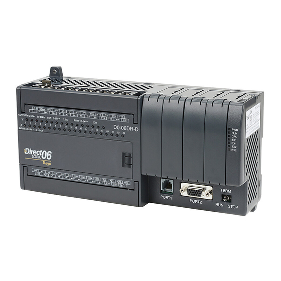
-
Contents
-
Table of Contents
-
Bookmarks
Quick Links
DL05/06 Option Modules
USER MANUAL
Manual Number: D0-OPTIONS-M
Related Manuals for Automationdirect.com DL06
Summary of Contents for Automationdirect.com DL06
-
Page 1
DL05/06 Option Modules USER MANUAL Manual Number: D0-OPTIONS-M… -
Page 2
Copyright 2018, AutomationDirect.com Incorporated All Rights Reserved No part of this manual shall be copied, reproduced, or transmitted in any way without the prior, written consent of AutomationDirect.com Incorporated. AutomationDirect retains the exclusive rights to all information included in this document. -
Page 3
Esta publicación puede contener referencias a productos producidos y/u ofrecidos por otras compañías. Los nombres de las compañías y productos pueden tener marcas registradas y son propiedad única de sus respectivos dueños. Automationdirect.com, renuncia cualquier interés propietario en las marcas y nombres de otros. -
Page 4
Nulle partie de ce manuel ne doit être copiée, reproduite ou transmise de quelque façon que ce soit sans le consentement préalable écrit de la société Automationdirect.com Incorporated. AutomationDirect conserve les droits exclusifs à l’égard de tous les renseignements contenus dans le présent document. -
Page 5
01/02 Added new chapter and minor changes to chapters 3rd edition 05/02 Added wiring guidelines and new discrete module 4th edition 07/02 Added DL06 micro PLC information 4th edition 02/03 Minor changes and corrections Rev. A 5th edition 05/03 Added new chapter… -
Page 6: Table Of Contents
Conventions Used …………………. 1–2 Key Topics for Each Chapter ………………1–2 Selecting the Proper Module ………………1–3 DL05 ……………………1–3 DL06 ……………………1–3 Module Choices ………………….. 1–3 Module Choices, continued………………1–4 Installing the Option Modules ……………… 1–5 Remove the Slot Cover ………………… 1–5 Insert the Module …………………
-
Page 7
Table of Contents Emergency Power Disconnect ……………… 2–4 Orderly System Shutdown ………………2–4 Class 1, Division 2 Approval (Applies ONLY to modules used with a DL06 PLC.) ..2–4 System Wiring Strategies ………………2–5 PLC Isolation Boundaries ………………2–5 I/O “Common” Terminal Concepts …………….2–8 Connecting DC I/O to Solid State Field Devices ………… -
Page 8
DL05 Data Formatting ………………… 3–7 Structure of V7700 ………………..3–7 Structure of V7701 ………………..3–7 DL06 Data Formatting ………………… 3–8 Setup Data Type and Number of Channels ………….. 3–8 Storage Pointer Setup ………………..3–8 Using the Pointer in Your Control Program …………. 3–9 DL05 Pointer Method ……………….. -
Page 9
DL05 Pointer Method Using the IBox Instruction Available in DirectSOFT5 ….4–9 DL06 Pointer Method Using Conventional Ladder Logic ……..4–10 DL06 Pointer Method Using the IBox Instruction Available in DirectSOFT6 …. 4–11 DL05/06 Option Modules User Manual; 7th Ed. Rev. C… -
Page 10
Resolution Details ………………..4–14 Analog Input Ladder Logic Filter …………….4–15 PID Loops / Filtering ………………..4–15 Smoothing the Input Signal (DL06 only) …………..4–15 Binary Data Format Filter Using Ladder Logic …………4–15 BCD Data Format Filter Using Ladder Logic…………4–16 Example Code to Scale a 4–20 mA Signal to 0–1000 BCD …….. -
Page 11
Resolution Details ………………..5–14 Analog Input Ladder Logic Filter …………….5–15 PID Loops / Filtering: ………………..5–15 Smoothing the Input Signal (DL06 only): …………… 5–15 Using Binary Data Format………………5–15 Using BCD Data Format ………………5–16 Chapter 6 — F0-08ADH-2, 8-Channel Analog Voltage Input Module Specifications ……………….. -
Page 12
DL05 Pointer Method Using the IBox Instruction Available in DirectSOFT5 …. 6–10 DL06 Pointer Method Using Conventional Ladder Logic ……..6–11 DL06 Pointer Method Using the IBox Instruction Available in DirectSOFT5 …. 6–12 Scale Conversions ………………..6–12 Scaling the Input Data ………………. 6–12 The Conversion Program in Standard Ladder Logic ………. -
Page 13
DL05 Pointer Method Using the IBox Instruction Available in DirectSOFT5 ….7–9 DL06 Pointer Method Using Conventional Ladder Logic ……..7–10 DL06 Pointer Method Using the IBox Instruction Available in DirectSOFT5 …. 7–11 Output Scale Conversion ………………7–11 Calculating the Digital Output Value …………..7–11 The Conversion Program in Standard Ladder Logic ………. -
Page 14
DL05 Pointer Method Using the IBox Instruction Available in DirectSOFT6 ….9–9 DL06 Pointer Method Using Conventional Ladder Logic ……..9–10 DL06 Pointer Method Using the IBox Instruction Available in DirectSOFT6 …. 9–11 Output Scale Conversion ………………9–11 Calculating the Digital Output Value …………..9–11 The Conversion Program in Standard Ladder Logic ………. -
Page 15
DL05 Pointer Method Using the IBox Instruction Available in DirectSOFT6 …. 10–9 DL06 Pointer Method Using Conventional Ladder Logic ……..10–10 DL06 Pointer Method Using the IBox Instruction Available in DirectSOFT6 ..10–11 Output Scale Conversion ………………10–11 Calculating the Digital Output Value …………..10–11 The Conversion Program in Standard Ladder Logic ………. -
Page 16
Structure of V7700 ………………..11–8 Structure of V7701 ………………..11–8 Structure of V7702 ………………..11–9 DL06 Data Formatting ………………11–10 Setup Data Type and Number of Channels …………11–10 Input Storage Pointer Setup …………….. 11–10 Output Storage Pointer Setup …………….11–10 Using the Pointer in Your Control Program ………… -
Page 17
Resolution Details ………………..11–18 Analog Input Ladder Logic Filter …………….11–19 PID Loops / Filtering ………………… 11–19 Smoothing the Input Signal (DL06 only) ………….. 11–19 Using Binary Data Format………………11–19 Using BCD Data Format ………………11–20 Chapter 12 — F0-2AD2DA-2, 2-Channel In/2-Ch. Out Analog Voltage Combination Module Specifications ………………… -
Page 18
Analog Data Bits ………………..12–15 Analog Input Ladder Logic Filter …………….12–16 PID Loops / Filtering ………………… 12–16 Smoothing the Input Signal (DL06 only) ………….. 12–16 Using Binary Data Format………………12–16 Using BCD Data Format ………………12–17 Chapter 13 — F0-4AD2DA-2, 4-Channel In/2-Ch. Out Analog Voltage Combination Module Specifications ………………… -
Page 19
Resolution Details ………………..13–15 Analog Input Ladder Logic Filter …………….13–16 PID Loops / Filtering ………………… 13–16 Smoothing the Input Signal (DL06 only) ………….. 13–16 Using Binary Data Format………………13–16 Using BCD Data Format ………………13–17 Chapter 14 — F0-04RTD, 4-Channel RTC Input Module Specifications ………………… -
Page 20
Negative Temperatures 2’s Complement (Binary/Pointer Method) ……. 14–17 Analog Input Ladder Logic Filter …………….14–18 PID Loops / Filtering ………………… 14–18 Smoothing the Input Signal (DL06 only) ………….. 14–18 Using Binary Data Format………………14–18 Using BCD Data Format ………………14–19 RTD Burnout Detection Bits ……………… -
Page 21
Module Resolution 15-Bit Plus Sign (Bipolar Voltage Input) ……..15–18 Analog Input Ladder Logic Filter …………….15–19 PID Loops / Filtering ………………… 15–19 Smoothing the Input Signal (DL06 only) ………….. 15–19 Using Binary Data Format………………15–19 Using BCD Data Format ………………15–20 Thermocouple Burnout Detection Bits ………….. -
Page 22
hapter hapter hapter ettinG tarted In This Chapter… Introduction ………………….. 1–2 Conventions Used …………………. 1–2 Selecting the Proper Module ………………1–3 Installing the Option Modules ……………… 1–5 Module LED Indicator ………………..1–6 Power Budgeting ………………….. 1–6… -
Page 23: Chapter 1: Getting Started
PLC families. It will show you how to select and install an option module for your PLC. Supplemental Manuals You will either need a copy of the DL05 User Manual (D0–USER–M) or the DL06 User Manual (D0–06USER–M) at hand when incorporating any one of the option modules in your PLC.
-
Page 24: Selecting The Proper Module
The DL05 Micro PLC only has one option slot to install an option module. The proper selection of a module is dependent on the control application. DL06 The DL06 Micro PLC has four option slots. The option modules can also be added according to the control application. Module Choices There are over thirty option modules available.
-
Page 25: Module Choices, Continued
Chapter 1: Getting Started Module Choices, continued. Analog Modules Part Number Description F0-04AD-1 4-Channel Analog Input, Current F0-04AD-2 4-Channel Analog Input, Voltage F0-08ADH-1 8-Channel High-Resolution Analog Input, Current F0-08ADH-2 8-Channel High-Resolution Analog Input, Voltage F0-04DAH-1 4-Channel High-Resolution Analog Output, Current F0-04DAH-2 4-Channel High-Resolution Analog Output, Voltage F0-08DAH-1…
-
Page 26: Installing The Option Modules
Chapter 1: Getting Started Installing the Option Modules Before installing the option module in the DL05 option slot or the DL06 option slots set the necessary jumpers and/or dip switches on the module. Refer to the chapter(s) that pertains to the module(s) being installed.
-
Page 27: Module Led Indicator
I/O module is functioning properly. Power Budgeting The DL06 has four option card slots. To determine whether the combination of cards you select will have sufficient power, you will need to perform a power budget calculation. Power supplied Power is supplied from two sources, the internal base unit power supply and, if required, an external supply (customer furnished).
-
Page 28
Chapter 1: Getting Started DL06 Base Unit Power Required DL06 Power Supplied by Base Units Part Number 5 VDC (mA) 24 VDC (mA) Part Number 5 VDC (mA) 24 VDC (mA) D0-06AA 800mA none <1500mA 300mA D0-06xx D0-06AR 900mA none <2000mA… -
Page 29
hapter hapter hapter iscrete uiDelines In This Chapter… Safety Guidelines ………………….. 2–2 System Wiring Strategies ………………2–5 I/O Addressing ………………….2–15 Discrete I/O General Specifications ……………. 2–17 Glossary of Specification Terms …………….2–18 F0-08SIM 8-Point Simulator Input Module …………. 2–19 D0-10ND3 10-Point DC Input Module ………….. -
Page 30: Chapter 2: Discrete I/O Guidelines
The protection provided by the equipment may be impaired if this equipment is used in a manner not specified in this manual. A listing of our international affiliates is available on our Web site: http://www.automationdirect.com WARNING: Providing a safe operating environment for personnel and equipment is your responsibility and should be your primary goal during system planning and installation.
-
Page 31: Three Levels Of Protection
Chapter 2: Discrete I/O Guidelines Three Levels of Protection The publications mentioned provide many ideas and requirements for system safety. At a minimum, you should follow these regulations. Also, you should use the following techniques, which provide three levels of system control. •…
-
Page 32: Emergency Power Disconnect
Retract Class 1, Division 2 Approval (Applies ONLY to modules used with a DL06 PLC.) This equipment is suitable for use in Class 1, Division 2, groups A, B, C and D or non- hazardous locations only.
-
Page 33: System Wiring Strategies
Chapter 2: Discrete I/O Guidelines System Wiring Strategies The DirectLOGIC Micro PLCs are very flexible and will work in many different wiring configurations. By studying this section before actual installation, you can probably find the best wiring strategy for your application . This will help to lower system cost, wiring errors, and avoid safety problems.
-
Page 34
Chapter 2: Discrete I/O Guidelines The following figures show the internal layout of the DL05 and DL06 PLCs, as viewed from the front panels. To Programming Device or Operator Interface DL05 2 Comm. Ports Main Optional Power I/O Circuits Supply… -
Page 35
Chapter 2: Discrete I/O Guidelines Sinking/Sourcing Concepts Before going further in our study of wiring strategies, we must have a solid understanding of “sinking” and “sourcing” concepts. Use of these terms occurs frequently in input or output circuit discussions. It is the goal of this section to make these concepts easy to understand, further ensuring your success in installation. -
Page 36: I/O «Common» Terminal Concepts
Chapter 2: Discrete I/O Guidelines I/O “Common” Terminal Concepts In order for a PLC I/O circuit to operate, current must enter at one terminal and exit at another. Field Main Path Device (I/O point) This means at least two terminals are associated Circuit with every I/O point.
-
Page 37: Connecting Dc I/O To Solid State Field Devices
The six outputs of the DL05 have the same electrical common, even though there are two common terminal screws. Not so with the DL06 which has four isolated commons. Finally, recall that the DC output circuit…
-
Page 38
Chapter 2: Discrete I/O Guidelines In the next example we connect a PLC DC output point to the sinking input of a field device. This is a bit tricky, because both the PLC output and field device input are sinking type. -
Page 39: Relay Output Guidelines
Chapter 2: Discrete I/O Guidelines Relay Output Guidelines Relay outputs are available for the DirectLOGIC PLCs. Relays are best for the following applications: • Loads that require higher currents than the solid-state outputs can deliver • Cost-sensitive applications • Some output channels need isolation from other outputs (such as when some loads require different voltages than other loads) Some applications in which NOT to use relays: •…
-
Page 40: Surge Suppression For Inductive Loads
Chapter 2: Discrete I/O Guidelines Surge Suppression For Inductive Loads Inductive load devices (devices with a coil) generate transient voltages when de-energized with a relay contact. When a relay contact is closed it “bounces”, which energizes and de-energizes the coil until the “bouncing” stops. The transient voltages generated are much larger in amplitude than the supply voltage, especially with a DC supply voltage.
-
Page 41: Prolonging Relay Contact Life
Chapter 2: Discrete I/O Guidelines Use the following table to help select a TVS or MOV suppressor for your application based on the inductive load voltage. Surge Suppressors Vendor / Catalog Type Inductive Load Voltage Part Number AutomationDirect 110/120 VAC ZL-TD8-120 24VDC ZL-TD8-24…
-
Page 42: Dc Input Wiring Methods
DC voltages from one load to another. • The DL06 has isolated commons for each group of four outputs. There are two DL06 models with output switches that are current-sinking only, and one that has sourcing output switches.
-
Page 43: I/O Addressing
The following table shows the number of I/O points per module when used in the DL05 PLC or the first slot of a DL06 PLC that has a discrete module installed. Discrete I/O addressing for a DL06 is automatic from slot 1 to slot 4 by default.
-
Page 44: All Discrete Modules Installed I/O Addressing Example
Chapter 2: Discrete I/O Guidelines All Discrete Modules Installed I/O Addressing Example: Slot 1 Slot 2 Slot 3 Slot 4 16pt Input 4pt Input 10pt Output 8pt Output AC ( L ) AC ( N ) 24V N.C. (discrete) 4pt Output (discrete) (discrete) OUTPUT: 6–240V…
-
Page 45: Discrete I/O General Specifications
The following is a list of general specifications for the discrete I/O option modules that are available for both the DL05 and DL06 PLCs. Also shown is information on the various removable connectors that are used for field wiring on the discrete I/O option modules along with reference to the ZIPLink connection system products that are available for the 16-point I/O modules.
-
Page 46: Glossary Of Specification Terms
Chapter 2: Discrete I/O Guidelines Glossary of Specification Terms Discrete Input One of the input connections to the PLC which converts an electrical signal from a field device to a binary status (OFF or ON), which is read by the internal CPU each PLC scan. Discrete Output One of the output connections from the PLC which converts an internal ladder program result (0 or 1) to turn ON or OFF an output switching device.
-
Page 47: F0-08Sim 8-Point Simulator Input Module
NOTE: The DL05 CPU’s discrete feature for the F0-08SIM module requires DirectSOFT32 Version 3.0c (or later) and firmware version 4.90 (or later). The DL06 requires DirectSOFT32 version V4.0, build 16 (or later) and firmware version 1.80 (or later). See our website for more information: www.
-
Page 48: D0-10Nd3 10-Point Dc Input Module
NOTE: The DL05 CPU’s discrete feature for this module requires DirectSOFT32 Version 3.0c (or later) and firmware version 4.10 (or later). The DL06 requires DirectSOFT32 version V4.0, build 16 (or later) and firmware version 1.00 (or later). See our website for more information: www.
-
Page 49: D0-10Nd3F 10-Point Dc Fast Input Module
NOTE: The DL05 CPU’s discrete feature for this module requires DirectSOFT32 Version 3.0c (or later) and firmware version 4.70 (or later). The DL06 requires DirectSOFT32 version V4.0, build 16 (or later) and firmware version 1.50 (or later). See our website for more information: www.automationdirect.
-
Page 50: D0-16Nd3 16-Point Dc Input Module
53.9(D) requires DirectSOFT32 Version 3.0c (or later) and Weight 20g (0.71 oz.) firmware version 4.10 (or later). The DL06 requires DirectSOFT32 version V4.0, build 16 (or later) and firmware version 1.00 (or later). See our website for Derating chart more information: www.automationdirect.com.
-
Page 51: F0-08Na-1 8-Point Ac Input Module
F0-08NA-1 NOTE: The DL05 CPU’s discrete feature for this module requires DirectSOFT32 Version 3.0c (or later) and firmware version 4.70 (or later). The DL06 requires DirectSOFT32 version V4.0, build 16 (or later) and firmware version 1.50 (or later). See our website for more information: www.automationdirect.com.
-
Page 52: D0-10Td1 10-Point Dc Output Module
NOTE: The DL05 CPU’s discrete feature for this module requires DirectSOFT32 Version 3.0c (or later) and firmware version 4.10 (or later). The DL06 requires DirectSOFT32 version V4.0, build 16 (or later) and firmware version 1.00 (or later). See our website for more information: www.automationdirect.com.
-
Page 53: D0-16Td1 16-Point Dc Output Module
NOTE: The DL05 CPU’s discrete feature for this module requires DirectSOFT32 Version 3.0c (or later) and firmware version 4.10 (or later). The DL06 requires DirectSOFT32 version V4.0, build 16 (or later) and firmware version 1.00 (or later). See our website for more information: www.automationdirect.com.
-
Page 54: D0-10Td2 10-Point Dc Output Module
NOTE: The DL05 CPU’s discrete feature for this module requires DirectSOFT32 Version 3.0c (or later) and firmware version 4.10 (or later). The DL06 requires DirectSOFT32 version V4.0, build 16 (or later) and firmware version 1.00 (or later). See our website for more information: www.automationdirect.com.
-
Page 55: D0-16Td2 16-Point Dc Output Module
NOTE: The DL05 CPU’s discrete feature for this module requires DirectSOFT32 Version 3.0c (or later) and firmware version 4.10 (or later). The DL06 requires DirectSOFT32 version V4.0, build 16 (or later) and firmware version 1.00 (or later). See our website for more information: www.automationdirect.com.
-
Page 56: D0-07Cdr 4-Point Dc Input, 3-Point Relay Output Module
NOTE: The DL05 CPU’s discrete feature for this module requires DirectSOFT32 Version 3.0c (or later) and firmware version 4.10 (or later). The DL06 requires DirectSOFT32 version V4.0, build 16 (or later) and firmware version 1.00 (or later). See our website for more information: www.automationdirect.com.
-
Page 57: D0-08Tr 8-Point Relay Output Module
NOTE: The DL05 CPU’s discrete feature for this module requires DirectSOFT32 Version 3.0c (or later) and firmware version 4.10 (or later). The DL06 requires DirectSOFT32 version V4.0, build 16 (or later) and firmware version 1.00 (or later). See our website for more information: www.automationdirect.com.
-
Page 58: D0-08Cdd1 4-Point Dc Input, 4-Point Dc Output Module
NOTE: The DL05 CPU’s discrete feature for this module requires DirectSOFT32 Version 3.0c (or later) and firmware version 4.10 (or later). The DL06 requires DirectSOFT32 version V4.0, build 16 (or later) and firmware version 1.00 (or later). See our website for more information: www.automationdirect.com.
-
Page 59: F0-04Trs 4-Point Relay Output Module
NOTE: The DL05 CPU’s discrete feature for this module requires DirectSOFT32 Version 3.0c (or later) and firmware version 4.70 (or later). The DL06 requires DirectSOFT32 version V4.0, build 16 (or later) and firmware version 1.50 (or later). See our website for more information: www.automationdirect.com.
-
Page 60
F0-04AD-1, hapter hapter hapter hAnnel nAlog urrent nput In This Chapter… Module Specifications ………………..3–2 Setting the Module Jumper ………………3–4 Connecting and Disconnecting the Field Wiring …………. 3–4 Wiring Diagram ………………….3–5 Module Operation ………………… 3–6 Special V-memory Locations ………………3–7 Using the Pointer in Your Control Program …………. -
Page 61: Chapter 3: F0-04Ad-1, 4-Channel Analog Current Input
NOTE: The DL05 CPU’s analog feature for this module requires DirectSOFT32 Version 3.0c (or later) and firmware version 2.10 (or later). The DL06 requires DirectSOFT32 version V4.0, build 16 (or later) and firmware version 1.00 (or later). See our website for more information: www.automationdirect.com.
-
Page 62
Chapter 3: F0-04AD-1, 4-Channel Analog Current Input The following tables provide the specifications for the F0–04AD–1 Analog Input Module. Review these specifications to make sure the module meets your application requirements. Input Specifications Number of Channels 4, single ended (one common) Input Range 0 to 20mA or 4 to 20mA current (jumper selectable) Resolution… -
Page 63: Setting The Module Jumper
Chapter 3: F0-04AD-1, 4-Channel Analog Current Input Setting the Module Jumper The position of jumper J3 determines the input signal level. You can choose between 4–20 mA and 0–20 mA. The module ships with the jumper not connecting the two pins. In this position, the expected input signal is 4–20 mA.
-
Page 64: Wiring Diagram
Chapter 3: F0-04AD-1, 4-Channel Analog Current Input Wiring Diagram Use the following diagram to connect the field wiring. If necessary, the F0–04AD–1 terminal block can be removed to make removal of the module possible without disturbing field wiring. Typical User Wiring Internal See NOTE 1 Module…
-
Page 65: Module Operation
Module Operation Channel Scanning Sequence The DL05 and DL06 will read all four channels of input data during each scan. Each CPU supports special V-memory locations that are used to manage the data transfer. This is discussed in more detail beginning in the section on “Special V-memory Locations”.
-
Page 66: Special V-Memory Locations
Chapter 3: F0-04AD-1, 4-Channel Analog Current Input Special V-memory Locations Formatting the Module Data The DL05 and DL06 PLCs have special V-memory locations assigned to their respective option slots. These V-memory locations allow you to: • Specify the data format (binary or BCD) •…
-
Page 67: Dl06 Data Formatting
Chapter 3: F0-04AD-1, 4-Channel Analog Current Input DL06 Data Formatting Special V-memory locations are assigned to the four option slots of the DL06 PLC. The table below shows these V-memory locations which can be used to setup the F0–04AD–1. Analog Input Module DL06 Special V-memory Locations Slot No.
-
Page 68: Using The Pointer In Your Control Program
Chapter 3: F0-04AD-1, 4-Channel Analog Current Input Using the Pointer in Your Control Program DL05 Pointer Method The DL05 CPU examines the pointer values (the memory locations identified in V7700 and V7701) on the first scan only. The example program below shows how to setup these locations. This rung can be placed anywhere in the ladder program or in the initial stage if you are using stage programming instructions.
-
Page 69: Dl06 Pointer Method
Use the special V-memory table below as a guide to setup the storage pointer in the following example for the DL06. Slot 1 is the left most option slot. The CPU will examine the pointer values at these locations only after a mode transition.
-
Page 70: Detecting Input Signal Loss
Chapter 3: F0-04AD-1, 4-Channel Analog Current Input Detecting Input Signal Loss Analog Signal Loss The F0–04AD–1 analog module can sense the loss of analog input signals in 4–20 mA loops. The Special Relays described on page 3–14 allow you to use this feature in your ladder program. For example, in the rung below SP610 is used to pull-in coil Y1, which would be used to open or close an external circuit.
-
Page 71: The Conversion Program
Chapter 3: F0-04AD-1, 4-Channel Analog Current Input The Conversion Program The following example shows how you would write the program to perform the engineering unit conversion. This example assumes you have BCD data loaded into the appropriate V-memory locations using instructions that apply for the model of CPU you are using. Note: this example uses SP1, which is always on.
-
Page 72: Special Relays
Chapter 3: F0-04AD-1, 4-Channel Analog Current Input Special Relays The list of other Special Relays associated with the DL05 and DL06 PLCs are contained in the DL05 User Manual and the DL06 User Manual. The following special relays are new and relate to the status of the F0–04AD–1 module or one of its input channels.
-
Page 73
Chapter 3: F0-04AD-1, 4-Channel Analog Current Input DL06 Special Relays (cont’d) SLOT 3 SP340 Chan 1 input type 0 = 0–20 mA 1 = 4–20 mA SP341 Chan 2 input type 0 = 0–20 mA 1 = 4–20 mA SP342 Chan 3 input type 0 = 0–20 mA… -
Page 74: Module Resolution
Chapter 3: F0-04AD-1, 4-Channel Analog Current Input Module Resolution Analog Data Bits The first twelve bits represent the analog data in binary format. Value Value 9 8 7 6 5 4 3 2 1 = data bits 1024 2048 Resolution Details Since the module has 12-bit resolution, the analog signal is converted into 4096 counts ranging from 0 — 4095 (2 ).
-
Page 75: Analog Input Ladder Logic Filter
Analog Input Ladder Logic Filter PID Loops / Filtering: Please refer to the “PID Loop Operation” chapter in the DL06 or DL05 User Manual for information on the built-in PV filter (DL05/06) and the ladder logic filter (DL06 only) shown below.
-
Page 76: Using Bcd Data Format
Chapter 3: F0-04AD-1, 4-Channel Analog Current Input NOTE: Be careful not to do a multiple number conversion on a value. For example, if you are using the pointer method in BCD format to get the analog value, it must be converted to binary (BIN) as shown below.
-
Page 77
F0-08ADH-1, hapter hapter hapter HAnnel nAlog urrent nput In This Chapter… Module Specifications ………………..4–2 Connecting and Disconnecting the Field Wiring …………. 4–4 Wiring Diagram ………………….4–5 Module Operation ………………… 4–6 Special V-memory Locations ………………4–7 Using the Pointer in Your Control Program …………. 4–9 Scale Conversions ……………….. -
Page 78: Chapter 4: F0-08Adh-1, 8-Channel Analog Current Input
NOTE: The DL05 CPU’s analog feature for this module requires DirectSOFT32 Version 3.0c (or later) and firmware version 5.20 (or later). The DL06 requires DirectSOFT32 version V4.0, build 16 (or later) and firmware version 2.30 (or later). See our website for more information: www.automationdirect.com.
-
Page 79
RFI, (145MHz, 440Mhz 5W @ 15cm); Worst case error during noise disturbance is 0.5% of full scale Agency Approvals UL508; UL60079-15 Zone 2 Module Location Any slot in a DL05 or DL06 System Field Wiring Removable Terminal Block Weight 49g (1.7 oz.) 4–3… -
Page 80: Connecting And Disconnecting The Field Wiring
Chapter 4: F0-08ADH-1, 8-Channel Analog Current Input Connecting and Disconnecting the Field Wiring WARNING: Before removing the analog module or the terminal block on the face of the module, disconnect power to the PLC and all field devices. Failure to disconnect power can result in damage to the PLC and/or field devices.
-
Page 81: Wiring Diagram
Chapter 4: F0-08ADH-1, 8-Channel Analog Current Input Wiring Diagram Use the following diagram to connect the field wiring. If necessary, the F0–08ADH–1 terminal block can be removed to make removal of the module possible without disturbing field wiring. Typical User Wiring Internal Module Circuitry CH1 ADC 2-wire 4–20mA…
-
Page 82: Module Operation
Module Operation Channel Scanning Sequence The DL05 and DL06 will read all eight channels of input data during each scan. Each CPU supports special V-memory locations that are used to manage the data transfer. This is discussed in more detail beginning in the section on “Special V-memory Locations”.
-
Page 83: Special V-Memory Locations
Chapter 4: F0-08ADH-1, 8-Channel Analog Current Input Special V-memory Locations Formatting the Analog Module Data The DL05 and DL06 PLCs have special V-memory locations assigned to their respective option slots. These V-memory locations allow you to: • Specify the data format (binary or BCD) •…
-
Page 84: Dl06 Data Formatting
Chapter 4: F0-08ADH-1, 8-Channel Analog Current Input DL06 Data Formatting Special V-memory locations are assigned to the four option slots of the DL06 PLC. The table below shows these V-memory locations which can be used to setup the F0–08ADH–1. Analog Input Module DL06 Special V-memory Locations Slot No.
-
Page 85: Using The Pointer In Your Control Program
Chapter 4: F0-08ADH-1, 8-Channel Analog Current Input Using the Pointer in Your Control Program DL05 Pointer Method Using Conventional Ladder Logic NOTE: The proper use of the DL05 pointer requires that the V-memory address be written to the special memory location on the first scan only. Use the SP0 bit as a permissive contact when using the code shown below.
-
Page 86: Dl06 Pointer Method Using Conventional Ladder Logic
The F0–08ADH–1 can be installed in any available DL06 option slot. The ladder diagram below shows how to set up these locations with the module installed in slot 1 of the DL06. Use the above table to determine the pointer values if locating the module in any of the other slot locations.
-
Page 87: Dl06 Pointer Method Using The Ibox Instruction Available In Directsoft6
Chapter 4: F0-08ADH-1, 8-Channel Analog Current Input DL06 Pointer Method Using the IBox Instruction Available in DirectSOFT6 The following logic accomplishes the same thing as the previous ladder example, but it uses the IBox instruction ANLGIN. Analog Input Module Pointer Setup…
-
Page 88: The Conversion Program In Standard Ladder Logic
Chapter 4: F0-08ADH-1, 8-Channel Analog Current Input The Conversion Program in Standard Ladder Logic The following example shows how you would write the program to perform the engineering unit conversion. This example assumes you have BCD data loaded into the appropriate V-memory locations using instructions that apply for the model of CPU you are using.
-
Page 89: Analog And Digital Value Conversions
Chapter 4: F0-08ADH-1, 8-Channel Analog Current Input Analog and Digital Value Conversions Sometimes it is useful to convert between the signal levels and the digital values. This is especially helpful during machine start-up or troubleshooting. The following table provides formulas to make this conversion easier. Range If you know the digital value If you know the analog signal level…
-
Page 90: Module Resolution
Chapter 4: F0-08ADH-1, 8-Channel Analog Current Input Module Resolution Analog Data Bits Two 16-bit words are reserved for the analog data whether you are using BCD or binary data formatting. The 16 bits in the low word represent the analog data in binary format. BCD Example V2001 V2000…
-
Page 91: Analog Input Ladder Logic Filter
Analog Input Ladder Logic Filter PID Loops / Filtering Please refer to the “PID Loop Operation” chapter in the DL06 or DL05 User Manual for information on the built-in PV filter (DL05/06) and the ladder logic filter (DL06 only) shown below.
-
Page 92: Bcd Data Format Filter Using Ladder Logic
Chapter 4: F0-08ADH-1, 8-Channel Analog Current Input NOTE: Be careful not to do a multiple number conversion on a value. For example, if you are using the pointer method in BCD format to get the analog value, it must be converted to binary (BIN) as shown below. If you are using the pointer method in Binary format, the conversion to binary (BIN) instruction is not needed.
-
Page 93: Example Code To Scale A 4-20 Ma Signal To 0-1000 Bcd
Chapter 4: F0-08ADH-1, 8-Channel Analog Current Input Example Code to Scale a 4–20 mA Signal to 0–1000 BCD (For applications where the field transmitter sends a 4–20 mA signal to the analog input card.) This example will scale the first input, a double word BCD value located at V2000 and V2001, as a 4–20 mA input signal from 0–1000.
-
Page 94: Example Code To Scale A 4-20 Ma Signal To 0-1000 Binary
Chapter 4: F0-08ADH-1, 8-Channel Analog Current Input Example Code to Scale a 4–20 mA Signal to 0–1000 Binary (For applications where the field transmitter sends a 4–20 mA signal to the analog input card.) This example will scale the first input, a binary/decimal value located at V2000 (the CPU reserves two words for each channel so V2000 and V2001 are reserved), as a 4–20 mA input signal from 0–1000.
-
Page 95
F0-04AD-2, hapter hapter hapter hAnnel nAlog oltAge nput In This Chapter… Module Specifications ………………..5–2 Setting the Module Jumpers ………………5–4 Connecting and Disconnecting the Field Wiring …………. 5–5 Wiring Diagram ………………….5–5 Module Operation ………………… 5–6 Special V-memory Locations ………………5–7 Using the Pointer in Your Control Program …………. -
Page 96: Chapter 5 — F0-04Ad-2, 4-Channel Analog Voltage Input
NOTE: The DL05 CPU’s analog feature for this module requires DirectSOFT32 Version 3.0c (or later) and firmware version 2.10 (or later). The DL06 requires DirectSOFT32 version V4.0, build 16 (or later) and firmware version 1.00 (or later). See our website for more information: www.automationdirect.com.
-
Page 97
Chapter 5: F0-04AD-2 4-Ch. Analog Voltage Input The following tables provide the specifications for the F0–04AD–2 Analog Input Module. Review these specifications to make sure the module meets your application requirements. Input Specifications Number of Channels 4, single ended (one common) Input Range 0 to 5VDC or 0 to 10VDC (jumper selectable) Resolution… -
Page 98: Setting The Module Jumpers
Chapter 5: F0-04AD-2 4-Ch. Analog Voltage Input Setting the Module Jumpers The position of the J2 jumpers determines the input signal levels. You can choose between 0–5 VDC or 0–10 VDC. The module ships with the jumpers installed connecting the pins. In this position, the input signal level is 0–5 VDC.
-
Page 99: Connecting And Disconnecting The Field Wiring
Chapter 5: F0-04AD-2 4-Ch. Analog Voltage Input Connecting and Disconnecting the Field Wiring Wiring Guidelines Your company may have guidelines for wiring and cable installation. If so, you should check those before you begin the installation. Here are some general things to consider: •…
-
Page 100: Module Operation
Module Operation Input Channel Update Sequence The DL05 and DL06 read four channels of input data during each scan. The CPU supports special V-memory locations that are used to manage the data transfer. This is discussed in more detail on the next page, “Special V-memory Locations”.
-
Page 101: Special V-Memory Locations
Chapter 5: F0-04AD-2 4-Ch. Analog Voltage Input Special V-memory Locations Formatting the Module Data The DL05 and DL06 PLCs have special V-memory locations assigned to their respective option slots. These V-memory locations allow you to: • Specify the data format (binary or BCD) •…
-
Page 102: Dl06 Data Formatting
Chapter 5: F0-04AD-2 4-Ch. Analog Voltage Input DL06 Data Formatting Special V-memory locations are assigned to the four option module slots of the DL06 PLC. The table below shows these V-memory locations which can be used for the F0–04AD–2. Analog Input Module DL06 Special V-memory Locations Slot No.
-
Page 103: Using The Pointer In Your Control Program
Chapter 5: F0-04AD-2 4-Ch. Analog Voltage Input Using the Pointer in Your Control Program DL05 Pointer Method The DL05 CPU examines the pointer values (the memory locations identified in V7700 and V7701) on the first scan only. The example program below shows how to setup these locations. This rung can be placed anywhere in the ladder program or in the initial stage if you are using stage programming instructions.
-
Page 104: Dl06 Pointer Method
Use the special V-memory table below as a guide to setup the pointer values in the following example for the DL06. Slot 1 is the left most option slot. The CPU will examine the pointer values at these locations only after a mode transition, first scan only.
-
Page 105: Scale Conversions
Chapter 5: F0-04AD-2 4-Ch. Analog Voltage Input Scale Conversions Scaling the Input Data Units = A H – L Many applications call for measurements in 4095 engineering units, which can be more meaningful than raw data. Convert to engineering units using H = High limit of the engineering the formula shown to the right.
-
Page 106: The Conversion Program
Chapter 5: F0-04AD-2 4-Ch. Analog Voltage Input The Conversion Program The following example shows how you would write the program to perform the engineering unit conversion from input data formats 0–4095. This example assumes the raw input data read at V2000 is in BCD format. Note: this example uses SP1, which is always on.
-
Page 107: Analog And Digital Value Conversions
Chapter 5: F0-04AD-2 4-Ch. Analog Voltage Input Analog and Digital Value Conversions Sometimes it is useful to convert between the signal levels and the digital values. This is especially helpful during machine startup or troubleshooting. The following table provides formulas to make this conversion easier. Range If you know the digital value If you know the analog signal level…
-
Page 108: Module Resolution
Chapter 5: F0-04AD-2 4-Ch. Analog Voltage Input Module Resolution Analog Data Bits The first twelve bits represent the analog data in binary format. Value Value 9 8 7 6 5 4 3 2 1 = data bits 1024 2048 Resolution Details Since the module has 12-bit resolution, the analog voltage signal is converted into 4096 counts ranging from 0–4095 (2 ).
-
Page 109: Analog Input Ladder Logic Filter
Analog Input Ladder Logic Filter PID Loops / Filtering: Please refer to the “PID Loop Operation” chapter in the DL06 or DL05 User Manual for information on the built-in PV filter (DL05/06) and the ladder logic filter (DL06 only) shown below.
-
Page 110: Using Bcd Data Format
Chapter 5: F0-04AD-2 4-Ch. Analog Voltage Input NOTE: Be careful not to do a multiple number conversion on a value. For example, if you are using the pointer method in BCD format to get the analog value, it must be converted to binary (BIN) as shown below. If you are using the pointer method in Binary format, the conversion to binary (BIN) instruction is not needed.
-
Page 111
F0-08ADH-2, hapter hapter hapter HAnnel nAlog oltAge nput In This Chapter… Module Specifications ………………..6–2 Setting the Module Jumpers ………………6–4 Connecting and Disconnecting the Field Wiring …………. 6–5 Wiring Diagram ………………….6–6 Module Operation ………………… 6–7 Special V-memory Locations ………………6–8 Using the Pointer in Your Control Program ………… -
Page 112: Chapter 6: F0-08Adh-2, 8-Channel Analog Voltage Input
NOTE: The DL05 CPU’s analog feature for this module requires DirectSOFT32 Version 3.0c (or later) and firmware version 5.20 (or later). The DL06 requires DirectSOFT32 version V4.0, build 16 (or later) and firmware version 2.30 (or later). See our website for more information: www.automationdirect.com.
-
Page 113
RFI, (145MHz, 440MHz 5W @ 15cm); Worst case error during noise disturbance is 0.5% of full scale Agency Approvals UL508; UL60079-15 Zone 2 Module Location Any slot in a DL05 or DL06 System Field Wiring Removable Terminal Block Weight 49g (1.7 oz.) 6–3… -
Page 114: Setting The Module Jumpers
Chapter 6: F0-08ADH-2, 8-Channel Analog Voltage Input Setting the Module Jumpers The position of the jumper determines the input signal voltage levels. You can choose between 0–5 VDC or 0–10 VDC. The 0–5V position is the default position. With the jumper connecting the J5 posts, an input signal level of 0–5 VDC is selected.
-
Page 115: Connecting And Disconnecting The Field Wiring
Chapter 6: F0-08ADH-2, 8-Channel Analog Voltage Input Connecting and Disconnecting the Field Wiring WARNING: Before removing the analog module or the terminal block on the face of the module, disconnect power to the PLC and all field devices. Failure to disconnect power can result in damage to the PLC and/or field devices.
-
Page 116: Wiring Diagram
Chapter 6: F0-08ADH-2, 8-Channel Analog Voltage Input Wiring Diagram Use the following diagram to connect the field wiring. If necessary, the F0–08ADH–2 terminal block can be removed to make removal of the module possible without disturbing field wiring. Typical User Wiring Internal Module Circuitry CH1 ADC 3-wire Voltage…
-
Page 117: Module Operation
Module Operation Channel Scanning Sequence The DL05 and DL06 will read all eight channels of input data during each scan. Each CPU supports special V-memory locations that are used to manage the data transfer. This is discussed in more detail beginning in the section on “Special V-memory Locations”.
-
Page 118: Special V-Memory Locations
Chapter 6: F0-08ADH-2, 8-Channel Analog Voltage Input Special V-memory Locations Formatting the Analog Module Data The DL05 and DL06 PLCs have special V-memory locations assigned to their respective option slots. These V-memory locations allow you to: • Specify the data format (binary or BCD) •…
-
Page 119: Dl06 Data Formatting
Chapter 6: F0-08ADH-2, 8-Channel Analog Voltage Input DL06 Data Formatting Special V-memory locations are assigned to the four option slots of the DL06 PLC. The table below shows these V-memory locations which can be used to setup the F0–08ADH–2. Analog Input Module DL06 Special V-memory Locations Slot No.
-
Page 120: Using The Pointer In Your Control Program
Chapter 6: F0-08ADH-2, 8-Channel Analog Voltage Input Using the Pointer in Your Control Program DL05 Pointer Method Using Conventional Ladder Logic NOTE: The proper use of the DL05 pointer requires that the V-memory address be written to the special memory location on the first scan only. Use the SP0 bit as a permissive contact when using the code shown below.
-
Page 121: Dl06 Pointer Method Using Conventional Ladder Logic
The F0–08ADH–2 can be installed in any available DL06 option slot. The ladder diagram below shows how to set up these locations with the module installed in slot 1 of the DL06. Use the above table to determine the pointer values if locating the module in any of the other slot locations.
-
Page 122: Dl06 Pointer Method Using The Ibox Instruction Available In Directsoft5
Chapter 6: F0-08ADH-2, 8-Channel Analog Voltage Input DL06 Pointer Method Using the IBox Instruction Available in DirectSOFT5 The following logic accomplishes the same thing as the previous ladder example, but it uses the IBox instruction ANLGIN. Analog Input Module Pointer Setup…
-
Page 123: The Conversion Program In Standard Ladder Logic
Chapter 6: F0-08ADH-2, 8-Channel Analog Voltage Input The Conversion Program in Standard Ladder Logic The following example shows how you would write the program to perform the engineering unit conversion. This example assumes you have BCD data loaded into the appropriate V-memory locations using instructions that apply for the model of CPU you are using.
-
Page 124: Analog And Digital Value Conversions
Chapter 6: F0-08ADH-2, 8-Channel Analog Voltage Input Analog and Digital Value Conversions Sometimes it is useful to convert between the signal levels and the digital values. This is especially helpful during machine start-up or troubleshooting. The following table provides formulas to make this conversion easier. Range If you know the digital value If you know the analog signal level…
-
Page 125: Module Resolution
Chapter 6: F0-08ADH-2, 8-Channel Analog Voltage Input Module Resolution Analog Data Bits Two 16-bit words are reserved for the analog data whether you are using BCD or binary data formatting. The 16 bits in the low word represent the analog data in binary format. BCD Example V2001 V2000…
-
Page 126: Analog Input Ladder Logic Filter
Analog Input Ladder Logic Filter PID Loops / Filtering Please refer to the “PID Loop Operation” chapter in the DL06 or DL05 User Manual for information on the built-in PV filter (DL05/06) and the ladder logic filter (DL06 only) shown below.
-
Page 127: Using Bcd Data Format
Chapter 6: F0-08ADH-2, 8-Channel Analog Voltage Input NOTE: Be careful not to do a multiple number conversion on a value. For example, if you are using the pointer method in BCD format to get the analog value, it must be converted to binary (BIN) as shown below. If you are using the pointer method in Binary format, the conversion to binary (BIN) instruction is not needed.
-
Page 128
F0-04DAH-1, hapter hapter HAnnel nAlog urrent utput In This Chapter… Module Specifications ………………..7–2 Connecting and Disconnecting the Field Wiring …………. 7–4 Wiring Diagram ………………….7–5 Module Operation ………………… 7–6 Special V-memory Locations ………………7–7 Using the Pointer in Your Control Program …………. 7–9 Output Scale Conversion ……………… -
Page 129: Chapter 7: F0-04Dah-1, 4-Channel Analog Current Output
NOTE: The DL05 CPU’s analog feature for this module requires DirectSOFT32 Version 3.0c (or later) and firmware version 5.20 (or later). The DL06 requires DirectSOFT32 version V4.0, build 16 (or later) and firmware version 2.30 (or later). See our website for more information: www.automationdirect.com.
-
Page 130
440Mhz 5W @ 15cm); Worst case error during noise disturbance is 0.5% of full scale Agency Approvals UL508; UL60079-15 Zone 2 Module Location Any slot in a DL05 or DL06 System Field Wiring Removable Terminal Block Weight 49g (1.7 oz.) 7–3… -
Page 131: Connecting And Disconnecting The Field Wiring
Chapter 7: F0-04DAH-1, 4-Channel Analog Current Output Connecting and Disconnecting the Field Wiring WARNING: Before removing the analog module or the terminal block on the face of the module, disconnect power to the PLC and all field devices. Failure to disconnect power can result in damage to the PLC and/or field devices.
-
Page 132: Wiring Diagram
Chapter 7: F0-04DAH-1, 4-Channel Analog Current Output Wiring Diagram Use the following diagram to connect the field wiring. If necessary, the F0–04DAH–1 terminal block can be removed to make removal of the module possible without disturbing field wiring. Typical User Wiring Internal Module Circuitry 4-20mA Output Ch.
-
Page 133: Module Operation
Module Operation Channel Scanning Sequence The DL05 and DL06 will write all four channels of output data during each scan. Each CPU supports special V-memory locations that are used to manage the data transfer. This is discussed in more detail beginning in the section on “Special V-memory Locations.”…
-
Page 134: Special V-Memory Locations
Chapter 7: F0-04DAH-1, 4-Channel Analog Current Output Special V-memory Locations Formatting the Analog Module Data The DL05 and DL06 PLCs have special V-memory locations assigned to their respective option slots. These V-memory locations allow you to: • Specify the data format (binary or BCD) •…
-
Page 135: Dl06 Data Formatting
Chapter 7: F0-04DAH-1, 4-Channel Analog Current Output DL06 Data Formatting Special V-memory locations are assigned to the four option slots of the DL06 PLC. The table below shows these V-memory locations which can be used to setup the F0–04DAH–1. Analog Output Module DL06 Special V-memory Locations Slot No.
-
Page 136: Using The Pointer In Your Control Program
Chapter 7: F0-04DAH-1, 4-Channel Analog Current Output Using the Pointer in Your Control Program DL05 Pointer Method Using Conventional Ladder Logic NOTE: The proper use of the DL05 pointer requires that the V-memory address be written to the special memory location on the first scan only. Use the SP0 bit as a permissive contact when using the code shown below.
-
Page 137: Dl06 Pointer Method Using Conventional Ladder Logic
DL06 Pointer Method Using Conventional Ladder Logic NOTE: The proper use of the DL06 pointer requires that the V-memory address be written to the special memory location on the first scan only. Use the SP0 bit as a permissive contact when using the code shown below.
-
Page 138: Dl06 Pointer Method Using The Ibox Instruction Available In Directsoft5
Chapter 7: F0-04DAH-1, 4-Channel Analog Current Output DL06 Pointer Method Using the IBox Instruction Available in DirectSOFT5 The following logic accomplishes the same thing as the previous ladder example, but it uses the IBox instruction ANLGOUT. Analog Output Module Pointer Setup…
-
Page 139: The Conversion Program In Standard Ladder Logic
Chapter 7: F0-04DAH-1, 4-Channel Analog Current Output The Conversion Program in Standard Ladder Logic The following example shows how you would write the program to perform the engineering unit conversion. This example assumes you have BCD data loaded into the appropriate V-memory locations using instructions that apply for the model of CPU you are using.
-
Page 140: Analog And Digital Value Conversions
Chapter 7: F0-04DAH-1, 4-Channel Analog Current Output Analog and Digital Value Conversions Sometimes it is useful to convert between the signal levels and the digital values. This is especially helpful during machine startup or troubleshooting. The following table provides formulas to make this conversion easier. The formulas in the table show the relationship between A, the analog value, and D, the digital value.
-
Page 141: Module Resolution
Chapter 7: F0-04DAH-1, 4-Channel Analog Current Output Module Resolution Analog Data Bits Two 16-bit words are reserved for the analog data whether you are using BCD or binary data formatting. The 16 bits in the low word represent the analog data in binary format. BCD Example V2001 V2000…
-
Page 142
F0-08DAH-1, hapter hapter hapter HAnnel nAlog urrent utput In This Chapter… Module Specifications ………………..8–2 Connecting and Disconnecting the Field Wiring …………. 8–4 Wiring Diagram ………………….8–5 Module Operation ………………… 8–6 Special System V-memory Locations …………….. 8–7 Using the Pointer in Your Control Program …………. 8–9 Output Scale Conversion ……………… -
Page 143: Chapter 8: F0-08Dah-1, 8-Channel Analog Current Output
NOTE: The DL05 CPU’s analog feature for this module requires DirectSOFT32 Version 3.0c (or later) and firmware version 5.20 (or later). The DL06 requires DirectSOFT32 version V4.0, build 16 (or later) and firmware version 2.30 (or later). See our website for more information: www.automationdirect.com.
-
Page 144
RFI, (145MHz, 440Mhz 5W @ 15cm); Worst case error during noise disturbance is 0.5% of full scale Agency Approvals UL508; UL60079-15 Zone 2 Module Location Any slot in a DL05 or DL06 System Field Wiring Removable Terminal Block Weight 49g (1.7 oz.) 8–3… -
Page 145: Connecting And Disconnecting The Field Wiring
Chapter 8: F0-08DAH-1, 8-Channel Analog Current Output Connecting and Disconnecting the Field Wiring WARNING: Before removing the analog module or the terminal block on the face of the module, disconnect power to the PLC and all field devices. Failure to disconnect power can result in damage to the PLC and/or field devices.
-
Page 146: Wiring Diagram
Chapter 8: F0-08DAH-1, 8-Channel Analog Current Output Wiring Diagram Use the following diagram to connect the field wiring. If necessary, the F0–08DAH–1 terminal block can be removed to make removal of the module possible without disturbing field wiring. Typical User Wiring Internal Module Circuitry 4-20mA Output Ch.
-
Page 147: Module Operation
Module Operation Channel Scanning Sequence The DL05 and DL06 will read all eight channels of output data during each scan. Each CPU supports special V-memory locations that are used to manage the data transfer. This is discussed in more detail beginning in the section on “Special V-memory Locations”.
-
Page 148: Special System V-Memory Locations
Chapter 8: F0-08DAH-1, 8-Channel Analog Current Output Special System V-memory Locations Formatting the Analog Module Data The DL05 and DL06 PLCs have system V-memory locations assigned to their respective option slots. These V-memory locations allow you to: • Specify the data format (binary or BCD) •…
-
Page 149: Dl06 Data Formatting
Chapter 8: F0-08DAH-1, 8-Channel Analog Current Output DL06 Data Formatting Special V-memory locations are assigned to the four option slots of the DL06 PLC. The table below shows these V-memory locations which can be used to setup the F0–08DAH–1. Analog Output Module DL06 Special V-memory Locations Slot No.
-
Page 150: Using The Pointer In Your Control Program
Chapter 8: F0-08DAH-1, 8-Channel Analog Current Output Using the Pointer in Your Control Program DL05 Pointer Method Using Conventional Ladder Logic NOTE: The proper use of the DL05 pointer requires that the V-memory address be written to the special memory location on the first scan only. Use the SP0 bit as a permissive contact when using the code shown below.
-
Page 151: Dl06 Pointer Method Using Conventional Ladder Logic
DL06 Pointer Method Using Conventional Ladder Logic NOTE: The proper use of the DL06 pointer requires that the V-memory address be written to the special memory location on the first scan only. Use the SP0 bit as a permissive contact when using the code shown below.
-
Page 152: Dl06 Pointer Method Using The Ibox Instruction Available In Directsoft5
Chapter 8: F0-08DAH-1, 8-Channel Analog Current Output DL06 Pointer Method Using the IBox Instruction Available in DirectSOFT5 The following logic accomplishes the same thing as the previous ladder example, but it uses the IBox instruction ANLGOUT. Analog Output Module Pointer Setup…
-
Page 153: The Conversion Program In Standard Ladder Logic
Chapter 8: F0-08DAH-1, 8-Channel Analog Current Output The Conversion Program in Standard Ladder Logic The following example shows how you would write the program to perform the engineering unit conversion. This example assumes you have BCD data loaded into the appropriate V-memory locations using instructions that apply for the model of CPU you are using.
-
Page 154: Analog And Digital Value Conversions
Chapter 8: F0-08DAH-1, 8-Channel Analog Current Output Analog and Digital Value Conversions Sometimes it is useful to convert between the signal levels and the digital values. This is especially helpful during machine startup or troubleshooting. The following table provides formulas to make this conversion easier. The formulas in the table show the relationship between A, the analog value, and D, the digital value.
-
Page 155: Module Resolution
Chapter 8: F0-08DAH-1, 8-Channel Analog Current Output Module Resolution Analog Data Bits Two 16-bit words are reserved for the analog data whether you are using BCD or binary data formatting. The 16 bits in the low word represent the analog data in binary format. BCD Example V2001 V2000…
-
Page 156
F0-04DAH-2, hapter hapter hapter HAnnel nAlog oltAge utput In This Chapter… Module Specifications ………………..9–2 Connecting and Disconnecting the Field Wiring …………. 9–4 Wiring Diagram ………………….9–5 Module Operation ………………… 9–6 Special V-memory Locations ………………9–7 Using the Pointer in Your Control Program …………. 9–9 Output Scale Conversion ……………… -
Page 157: Chapter 9: F0-04Dah-2, 4-Channel Analog Voltage Output
NOTE: The DL05 CPU’s analog feature for this module requires DirectSOFT32 Version 3.0c (or later) and firmware version 5.20 (or later). The DL06 requires DirectSOFT32 version V4.0, build 16 (or later) and firmware version 2.30 (or later). See our website for more information: www.automationdirect.com.
-
Page 158
RFI, (145MHz, 440Mhz 5W @ 15cm); Worst case error during noise disturbance is 0.5% of full scale Agency Approvals UL508; UL60079-15 Zone 2 Module Location Any slot in a DL05 or DL06 System Field Wiring Removable Terminal Block Weight 49g (1.7 oz.) 9–3… -
Page 159: Connecting And Disconnecting The Field Wiring
Chapter 9: F0-04DAH-2, 4-Channel Analog Voltage Output Connecting and Disconnecting the Field Wiring WARNING: Before removing the analog module or the terminal block on the face of the module, disconnect power to the PLC and all field devices. Failure to disconnect power can result in damage to the PLC and/or field devices.
-
Page 160: Wiring Diagram
Chapter 9: F0-04DAH-2, 4-Channel Analog Voltage Output Wiring Diagram Use the following diagram to connect the field wiring. If necessary, the F0–04DAH–2 terminal block can be removed to make removal of the module possible without disturbing field wiring. Typical User Wiring Internal Module Circuitry Voltage Output Ch.
-
Page 161: Module Operation
Module Operation Channel Scanning Sequence The DL05 and DL06 will read all four channels of output data during each scan. Each CPU supports special V-memory locations that are used to manage the data transfer. This is discussed in more detail beginning in the section on “Special V-memory Locations”.
-
Page 162: Special V-Memory Locations
Chapter 9: F0-04DAH-2, 4-Channel Analog Voltage Output Special V-memory Locations Formatting the Analog Module Data The DL05 and DL06 PLCs have special V-memory locations assigned to their respective option slots. These V-memory locations allow you to: • Specify the data format (binary or BCD) •…
-
Page 163: Dl06 Data Formatting
Chapter 9: F0-04DAH-2, 4-Channel Analog Voltage Output DL06 Data Formatting Special V-memory locations are assigned to the four option slots of the DL06 PLC. The table below shows these V-memory locations which can be used to setup the F0–04DAH–2. Analog Output Module DL06 Special V-memory Locations Slot No.
-
Page 164: Using The Pointer In Your Control Program
Chapter 9: F0-04DAH-2, 4-Channel Analog Voltage Output Using the Pointer in Your Control Program DL05 Pointer Method Using Conventional Ladder Logic NOTE: The proper use of the DL05 pointer requires that the V-memory address be written to the special memory location on the first scan only. Use the SP0 bit as a permissive contact when using the code shown below.
-
Page 165: Dl06 Pointer Method Using Conventional Ladder Logic
DL06 Pointer Method Using Conventional Ladder Logic NOTE: The proper use of the DL06 pointer requires that the V-memory address be written to the special memory location on the first scan only. Use the SP0 bit as a permissive contact when using the code shown below.
-
Page 166: Dl06 Pointer Method Using The Ibox Instruction Available In Directsoft6
Chapter 9: F0-04DAH-2, 4-Channel Analog Voltage Output DL06 Pointer Method Using the IBox Instruction Available in DirectSOFT6 The following logic accomplishes the same thing as the previous ladder example, but it uses the IBox instruction ANLGOUT. Analog Output Module Pointer Setup…
-
Page 167: The Conversion Program In Standard Ladder Logic
Chapter 9: F0-04DAH-2, 4-Channel Analog Voltage Output The Conversion Program in Standard Ladder Logic The following example shows how you would write the program to perform the engineering unit conversion. This example assumes you have BCD data loaded into the appropriate V-memory locations using instructions that apply for the model of CPU you are using.
-
Page 168: Analog And Digital Value Conversions
Chapter 9: F0-04DAH-2, 4-Channel Analog Voltage Output Analog and Digital Value Conversions Sometimes it is useful to convert between the signal levels and the digital values. This is especially helpful during machine startup or troubleshooting. The following table provides formulas to make this conversion easier. The formulas in the table show the relationship between A, the analog value, and D, the digital value.
-
Page 169: Module Resolution
Chapter 9: F0-04DAH-2, 4-Channel Analog Voltage Output Module Resolution Analog Data Bits Two 16-bit words are reserved for the analog data whether you are using BCD or binary data formatting. The 16 bits in the low word represent the analog data in binary format. BCD Example V2001 V2000…
-
Page 170
F0-08DAH-2, hapter hapter hapter HAnnel nAlog oltAge utput In This Chapter… Module Specifications ………………… 10–2 Connecting and Disconnecting the Field Wiring ……….. 10–4 Wiring Diagram ………………….. 10–5 Module Operation ………………..10–6 Special V-memory Locations ………………. 10–7 Using the Pointer in Your Control Program …………10–9 Output Scale Conversion ……………… -
Page 171: Chapter 10: F0-08Dah-2, 8-Channel Analog Voltage Output
NOTE: The DL05 CPU’s analog feature for this module requires DirectSOFT32 Version 3.0c (or later) and firmware version 5.20 (or later). The DL06 requires DirectSOFT32 version V4.0, build 16 (or later) and firmware version 2.30 (or later). See our website for more information: www.automationdirect.com.
-
Page 172
RFI, (145MHz, 440MHz 5W @ 15cm); Worst case error during noise disturbance is 0.5% of full scale Agency Approvals UL508; UL60079-15 Zone 2 Module Location Any slot in a DL05 or DL06 System Field Wiring Removable Terminal Block Weight 49g (1.7 oz.) 10–3… -
Page 173: Connecting And Disconnecting The Field Wiring
Chapter 10: F0-08DAH-2, 8-Channel Analog Voltage Output Connecting and Disconnecting the Field Wiring WARNING: Before removing the analog module or the terminal block on the face of the module, disconnect power to the PLC and all field devices. Failure to disconnect power can result in damage to the PLC and/or field devices.
-
Page 174: Wiring Diagram
Chapter 10: F0-08DAH-2, 8-Channel Analog Voltage Output Wiring Diagram Use the following diagram to connect the field wiring. If necessary, the F0–08DAH–2 terminal block can be removed to make removal of the module possible without disturbing field wiring. Typical User Wiring Internal Module Circuitry Voltage Output Ch.
-
Page 175: Module Operation
Module Operation Channel Scanning Sequence The DL05 and DL06 will read all eight channels of output data during each scan. Each CPU supports special V-memory locations that are used to manage the data transfer. This is discussed in more detail beginning in the section on “Special V-memory Locations”.
-
Page 176: Special V-Memory Locations
Chapter 10: F0-08DAH-2, 8-Channel Analog Voltage Output Special V-memory Locations Formatting the Analog Module Data The DL05 and DL06 PLCs have special V-memory locations assigned to their respective option slots. These V-memory locations allow you to: • Specify the data format (binary or BCD) •…
-
Page 177: Dl06 Data Formatting
Chapter 10: F0-08DAH-2, 8-Channel Analog Voltage Output DL06 Data Formatting Special V-memory locations are assigned to the four option slots of the DL06 PLC. The table below shows these V-memory locations which can be used to setup the F0–08DAH–2. Analog Output Module DL06 Special V-memory Locations Slot No.
-
Page 178: Using The Pointer In Your Control Program
Chapter 10: F0-08DAH-2, 8-Channel Analog Voltage Output Using the Pointer in Your Control Program DL05 Pointer Method Using Conventional Ladder Logic NOTE: The proper use of the DL05 pointer requires that the V-memory address be written to the special memory location on the first scan only. Use the SP0 bit as a permissive contact when using the code shown below.
-
Page 179: Dl06 Pointer Method Using Conventional Ladder Logic
DL06 Pointer Method Using Conventional Ladder Logic NOTE: The proper use of the DL06 pointer requires that the V-memory address be written to the special memory location on the first scan only. Use the SP0 bit as a permissive contact when using the code shown below.
-
Page 180: Dl06 Pointer Method Using The Ibox Instruction Available In Directsoft6
Chapter 10: F0-08DAH-2, 8-Channel Analog Voltage Output DL06 Pointer Method Using the IBox Instruction Available in DirectSOFT6 The following logic accomplishes the same thing as the previous ladder example, but it uses the IBox instruction ANLGOUT. Analog Output Module Pointer Setup…
-
Page 181: The Conversion Program In Standard Ladder Logic
Chapter 10: F0-08DAH-2, 8-Channel Analog Voltage Output The Conversion Program in Standard Ladder Logic The following example shows how you would write the program to perform the engineering unit conversion. This example assumes you have BCD data loaded into the appropriate V-memory locations using instructions that apply for the model of CPU you are using.
-
Page 182: Analog And Digital Value Conversions
Chapter 10: F0-08DAH-2, 8-Channel Analog Voltage Output Analog and Digital Value Conversions Sometimes it is useful to convert between the signal levels and the digital values. This is especially helpful during machine startup or troubleshooting. The following table provides formulas to make this conversion easier. The formulas in the table show the relationship between A, the analog value, and D, the digital value.
-
Page 183: Module Resolution
Chapter 10: F0-08DAH-2, 8-Channel Analog Voltage Output Module Resolution Analog Data Bits Two 16-bit words are reserved for the analog data whether you are using BCD or binary data formatting. The 16 bits in the low word represent the analog data in binary format. BCD Example V2001 V2000…
-
Page 184
F0-4AD2DA-1, /2-C hAnnel hapter hapter hapter nAlOg urrent OmbInAtIOn In This Chapter… Module Specifications ………………… 11–2 Setting the Module Jumper ………………11–4 Connecting and Disconnecting the Field Wiring ……….. 11–5 Wiring Diagram ………………….. 11–6 Module Operation ………………..11–7 Special V-memory Locations ………………. 11–8 Using the Pointer in Your Control Program ………… -
Page 185: Module Specifications
NOTE: The DL05 CPU’s analog feature for this module requires DirectSOFT32 Version 3.0c (or later) and firmware version 3.30 (or later). The DL06 requires DirectSOFT32 version V4.0, build 16 (or later) and firmware version 1.00 (or later). See our website for more information: www.automationdirect.com.
-
Page 186
Chapter 11: F0-4AD2DA-1, 4-Ch. In/2-Ch. Out Analog Current Combination The following tables provide the specifications for the F0–4AD2DA–1 Analog Combination Module. Review these specifications to make sure the module meets your application requirements. Input Specifications Number of Channels 4, single ended (one common) Input Range 0 to 20mA or 4 to 20mA (jumper selectable) Resolution… -
Page 187: Setting The Module Jumper
Chapter 11: F0-4AD2DA-1, 4-Ch. In/2-Ch. Out Analog Current Combination General Specifications PLC Update Rate 4 input channels per scan, 2 output channels per scan 16-bit Data Word 12 binary data bits Operating Temperature 0 to 60°C (32 to 140°F) Storage Temperature -20 to 70°C (-4 to 158°F) Relative Humidity 5 to 95% (non-condensing)
-
Page 188: Connecting And Disconnecting The Field Wiring
Chapter 11: F0-4AD2DA-1, 4-Ch. In/2-Ch. Out Analog Current Combination Connecting and Disconnecting the Field Wiring Wiring Guidelines Your company may have guidelines for wiring and cable installation. If so, you should check those before you begin the installation. Here are some general things to consider: •…
-
Page 189: Wiring Diagram
Chapter 11: F0-4AD2DA-1, 4-Ch. In/2-Ch. Out Analog Current Combination Wiring Diagram Use the following diagram to connect the field wiring. If necessary, the terminal block can be removed to make removal of the module possible without disturbing field wiring. Typical User Wiring Internal See NOTE 1 Module…
-
Page 190: Module Operation
Module Operation Input/Output Channel Update Sequence The DL05 and DL06 will read four channels of input data and two channels of output data during each scan. Each CPU supports special V-memory locations that are used to manage the data transfer. This is discussed in more detail beginning on the next page, “Special V-memory Locations”.
-
Page 191: Special V-Memory Locations
Chapter 11: F0-4AD2DA-1, 4-Ch. In/2-Ch. Out Analog Current Combination Special V-memory Locations Formatting the Module Data The DL05 and DL06 PLCs have three special V-memory locations assigned to their respective option slots. These V-memory locations allow you to: • Specify the data format (binary or BCD) •…
-
Page 192: Structure Of V7702
Chapter 11: F0-4AD2DA-1, 4-Ch. In/2-Ch. Out Analog Current Combination Structure of V7702 V7702 is a system parameter that points to a V-memory location used for storing analog output data. The V-memory location loaded in V7702 is an octal number identifying the first V-memory location for the analog output data.
-
Page 193: Dl06 Data Formatting
Chapter 11: F0-4AD2DA-1, 4-Ch. In/2-Ch. Out Analog Current Combination DL06 Data Formatting Special V-memory locations are assigned to the four option module slots of the DL06 PLC. The table below shows these V-memory locations which can be used by the F0–4AD2DA–1.
-
Page 194: Using The Pointer In Your Control Program
Chapter 11: F0-4AD2DA-1, 4-Ch. In/2-Ch. Out Analog Current Combination Using the Pointer in Your Control Program DL05 Pointer Method The DL05 CPU examines the pointer values (the memory locations identified in V7700, V7701 and V7702) on the first scan only. The example program below shows how to setup these locations for 4 input channels and 2 output channels.
-
Page 195: Dl06 Pointer Method
Use the special V-memory table as a guide to setup the pointer values in the following example for the DL06. Slot 1 is the left most option slot. The CPU will examine the pointer values at these locations only after a mode transition, first scan only.
-
Page 196: Scale Conversions
Chapter 11: F0-4AD2DA-1, 4-Ch. In/2-Ch. Out Analog Current Combination Scale Conversions Scaling the Input Data Many applications call for measurements in Units = A H – L engineering units, which can be more meaningful 4095 than raw data. Convert to engineering units using H = High limit of the engineering the formula shown to the right.
-
Page 197: The Conversion Program
0–1000 in BCD format and stored them in V2300 and V2301 for channels 1 and 2 respectively. Both the DL05 and DL06 offer instructions that allow you to perform math operations using BCD format. It is usually easier to perform any math calculations in BCD and then convert the value to binary before you send the data to the module.
-
Page 198: Analog And Digital Value Conversions
Chapter 11: F0-4AD2DA-1, 4-Ch. In/2-Ch. Out Analog Current Combination Analog and Digital Value Conversions Sometimes it is useful to convert between the signal levels and the digital values. This is especially helpful during machine startup or troubleshooting. The following tables provide formulas to make this conversion easier.
-
Page 199: Special Relays
Chapter 11: F0-4AD2DA-1, 4-Ch. In/2-Ch. Out Analog Current Combination Special Relays The list of other Special Relays associated with the DL05 and DL06 PLCs are contained in the DL05 User Manual and the DL06 User Manual. The following special relays are new and relate to the status of the F0–04AD2DA–1 module or one of its input channels.
-
Page 200
Chapter 11: F0-4AD2DA-1, 4-Ch. In/2-Ch. Out Analog Current Combination DL06 Special Relays (cont’d) SLOT 3 SP340 Chan 1 input type 0 = 0–20 mA 1 = 4–20 mA SP341 Chan 2 input type 0 = 0–20 mA 1 = 4–20 mA… -
Page 201: Module Resolution
Chapter 11: F0-4AD2DA-1, 4-Ch. In/2-Ch. Out Analog Current Combination Module Resolution Analog Data Bits The first twelve bits represent the analog data in binary format. Value Value 9 8 7 6 5 4 3 2 1 = data bits 1024 2048 Resolution Details Since the module has 12-bit resolution, the analog signal is converted from 4096 counts…
-
Page 202: Analog Input Ladder Logic Filter
Analog Input Ladder Logic Filter PID Loops / Filtering Please refer to the “PID Loop Operation” chapter in the DL06 or DL05 User Manual for information on the built-in PV filter (DL05/06) and the ladder logic filter (DL06 only) shown below.
-
Page 203: Using Bcd Data Format
Chapter 11: F0-4AD2DA-1, 4-Ch. In/2-Ch. Out Analog Current Combination NOTE: Be careful not to do a multiple number conversion on a value. For example, if you are using the pointer method in BCD format to get the analog value, it must be converted to binary (BIN) as shown below. If you are using the pointer method in Binary format, the conversion to binary (BIN) instruction is not needed.
-
Page 204
F0-2AD2DA-2 2-C hapter hapter hapter /2-C nAlOg OltAge OmbInAtIOn In This Chapter… Module Specifications ………………… 12–2 Setting the Module Jumpers ………………. 12–4 Connecting and Disconnecting the Field Wiring ……….. 12–5 Wiring Diagram ………………….. 12–5 Module Operation ………………..12–6 Special V-memory Locations ………………. 12–7 Using the Pointer in Your Control Program ………… -
Page 205: Module Specifications
NOTE: The DL05 CPU’s analog feature for this module requires DirectSOFT32 Version 3.0c (or later) and firmware version 3.30 (or later). The DL06 requires DirectSOFT32 version V4.0, build 16 (or later) and firmware version 1.00 (or later). See our website for more information: www.automationdirect.com.
-
Page 206
Chapter 12: F0-2AD2DA-2 2-Ch. In/2-Ch. Out Analog Voltage Combination The following tables provide the specifications for the F0–2AD2DA–2 Analog Voltage Combination Module. Review these specifications to make sure the module meets your application requirements. Input Specifications Number of Channels 2, single ended (one common) Input Range 0 to 5VDC or 0 to 10VDC (jumper selectable) Resolution… -
Page 207: Setting The Module Jumpers
Chapter 12: F0-2AD2DA-2 2-Ch. In/2-Ch. Out Analog Voltage Combination General Specifications 2 input channels per scan PLC Update Rate 2 output channels per scan 16-bit Data Word 12 binary data bits Operating Temperature 0 to 60° C (32 to 140° F) Storage Temperature -20 to 70°…
-
Page 208: Connecting And Disconnecting The Field Wiring
Chapter 12: F0-2AD2DA-2 2-Ch. In/2-Ch. Out Analog Voltage Combination Connecting and Disconnecting the Field Wiring Wiring Guidelines Your company may have guidelines for wiring and cable installation. If so, you should check those before you begin the installation. Here are some general things to consider: •…
-
Page 209: Module Operation
Module Operation Input/Output Channel Scanning Sequence The DL05 and DL06 read two channels of input and two channels of output data during each scan. The CPU supports special V-memory locations that are used to manage the data transfer. This is discussed in more detail on the following page, “Special V-memory Locations”.
-
Page 210: Special V-Memory Locations
Chapter 12: F0-2AD2DA-2 2-Ch. In/2-Ch. Out Analog Voltage Combination Special V-memory Locations Formatting the Module Data The DL05 and DL06 PLCs have three special V-memory locations assigned to their respective option slots These V-memory locations allow you to: • Specify the data format (binary or BCD) •…
-
Page 211: Structure Of V7702
Chapter 12: F0-2AD2DA-2 2-Ch. In/2-Ch. Out Analog Voltage Combination Structure of V7702 V7702 is a system parameter that points to a V-memory location used for storing analog output data. The V-memory location loaded in V7702 is an octal number identifying the first V-memory location for the analog output data.
-
Page 212: Dl06 Data Formatting
Chapter 12: F0-2AD2DA-2 2-Ch. In/2-Ch. Out Analog Voltage Combination DL06 Data Formatting Special V-memory locations are assigned to the four option module slots of the DL06 PLC. The table below shows these V-memory locations which can be used by the F0–2AD2DA–2.
-
Page 213: Using The Pointer In Your Control Program
Chapter 12: F0-2AD2DA-2 2-Ch. In/2-Ch. Out Analog Voltage Combination Using the Pointer in Your Control Program DL05 Pointer Method The DL05 CPU examines the pointer values (the memory locations identified in V7700, V7701 and V7702) on the first scan only. The example program below shows how to setup these locations for 2 input channels and 2 output channels.
-
Page 214: Dl06 Pointer Method
Use the special V-memory table as a guide to setup the pointer values in the following example for the DL06. Slot 1 is the left most option slot. The CPU will examine the pointer values at these locations only after a mode transition, first scan only.
-
Page 215: Scale Conversions
Chapter 12: F0-2AD2DA-2 2-Ch. In/2-Ch. Out Analog Voltage Combination Scale Conversions Scaling the Input Data Many applications call for measurements in engineering units, which can be more meaningful Units = A H – L than raw data. Convert to engineering units using 4095 the formula shown to the right.
-
Page 216: The Conversion Program
0–1000 in BCD format and stored them in V2300 and V2301 for channels 1 and 2 respectively. Both the DL05 and DL06 offer instructions that allow you to perform math operations using BCD format. It is usually easier to perform any math calculations in BCD and then convert the value to binary before you send the data to the module.
-
Page 217: Analog And Digital Value Conversions
Chapter 12: F0-2AD2DA-2 2-Ch. In/2-Ch. Out Analog Voltage Combination Analog and Digital Value Conversions Sometimes it is useful to convert between the signal levels and the digital values. This is especially helpful during machine startup or troubleshooting. The following table provides formulas to make this conversion easier.
-
Page 218: Module Resolution
Chapter 12: F0-2AD2DA-2 2-Ch. In/2-Ch. Out Analog Voltage Combination Module Resolution Analog Data Bits The first twelve bits represent the analog data for both inputs and outputs in binary format. Value Value 9 8 7 6 5 4 3 2 1 = data bits 1024 2048…
-
Page 219: Analog Input Ladder Logic Filter
Analog Input Ladder Logic Filter PID Loops / Filtering Please refer to the “PID Loop Operation” chapter in the DL06 or DL05 User Manual for information on the built-in PV filter (DL05/06) and the ladder logic filter (DL06 only) shown below.
-
Page 220: Using Bcd Data Format
Chapter 12: F0-2AD2DA-2 2-Ch. In/2-Ch. Out Analog Voltage Combination NOTE: Be careful not to do a multiple number conversion on a value. For example, if you are using the pointer method in BCD format to get the analog value, it must be converted to binary (BIN) as shown below. If you are using the pointer method in Binary format, the conversion to binary (BIN) instruction is not needed.
-
Page 221
F0-4AD2DA-2, 4-C hapter hapter hapter /2-C nAlOg OltAge OmbInAtIOn In This Chapter… Module Specifications ………………… 13–2 Setting the Module Jumpers ………………. 13–4 Connecting and Disconnecting the Field Wiring ……….. 13–5 Wiring Diagram ………………….. 13–5 Module Operation ………………..13–6 Special V-memory Locations ………………. 13–7 Using the Pointer in Your Control Program ………… -
Page 222: Module Specifications
NOTE: The DL05 CPU’s analog feature for this module requires DirectSOFT32 Version 3.0c (or later) and firmware version 3.30 (or later). The DL06 requires DirectSOFT32 version V4.0, build 16 (or later) and firmware version 1.00 (or later). See our website for more information: www.automationdirect.com.
-
Page 223
Chapter 13: F0-4AD2DA-2, 4-Ch. In/2 Ch. Out Analog Voltage Combination The following tables provide the specifications for the F0–4AD2DA–2 Analog Combination Module. Review these specifications to make sure the module meets your application requirements. Input Specifications Number of Channels 4, single ended (one common) Input Range 0 to 5VDC or 0 to 10VDC (jumper selectable) Resolution… -
Page 224: Setting The Module Jumpers
Chapter 13: F0-4AD2DA-2, 4-Ch. In/2 Ch. Out Analog Voltage Combination General Specifications 4 input channels per scan PLC Update Rate 2 output channels per scan 16-bit Data Word 12 binary data bits Operating Temperature 0 to 60° C (32 to 140° F) Storage Temperature -20 to 70°…
-
Page 225: Connecting And Disconnecting The Field Wiring
Chapter 13: F0-4AD2DA-2, 4-Ch. In/2 Ch. Out Analog Voltage Combination Connecting and Disconnecting the Field Wiring Wiring Guidelines Your company may have guidelines for wiring and cable installation. If so, you should check those before you begin the installation. Here are some general things to consider: •…
-
Page 226: Module Operation
Module Operation Input/Output Channel Update Sequence The DL05 and DL06 read four channels of input data and two channels of output data during each scan. The CPU supports special V-memory locations that are used to manage the data transfer. This is discussed in more detail on the next page, “Special V-memory Locations”.
-
Page 227: Special V-Memory Locations
Chapter 13: F0-4AD2DA-2, 4-Ch. In/2 Ch. Out Analog Voltage Combination Special V-memory Locations Formatting the Module Data The DL05 and DL06 PLCs have three special V-memory locations assigned to their respective option slots. These V-memory locations allow you to: • Specify the data format (binary or BCD) •…
-
Page 228: Structure Of V7702
Chapter 13: F0-4AD2DA-2, 4-Ch. In/2 Ch. Out Analog Voltage Combination Structure of V7702 V7702 is a system parameter that points to a V-memory location used for storing analog output data. The V-memory location loaded in V7702 is an octal number identifying the first V-memory location for the analog output data.
-
Page 229: Dl06 Data Formatting
Chapter 13: F0-4AD2DA-2, 4-Ch. In/2 Ch. Out Analog Voltage Combination DL06 Data Formatting Special V-memory locations are assigned to the four option module slots of the DL06 PLC. The table below shows these V-memory locations which can be used for the F0–4AD2DA–2.
-
Page 230: Using The Pointer In Your Control Program
Chapter 13: F0-4AD2DA-2, 4-Ch. In/2 Ch. Out Analog Voltage Combination Using the Pointer in Your Control Program DL05 Pointer Method The DL05 CPU examines the pointer values (the memory locations identified in V7700, V7701 and V7702) on the first scan only. The example program below shows how to setup these locations for 4 input channels and 2 output channels.
-
Page 231: Dl06 Pointer Method
Use the special V-memory table as a guide to setup the pointer values in the following example for the DL06. Slot 1 is the left most option slot. The CPU will examine the pointer values at these locations only after a mode transition, first scan only.
-
Page 232: Scale Conversions
Chapter 13: F0-4AD2DA-2, 4-Ch. In/2 Ch. Out Analog Voltage Combination Scale Conversions Scaling the Input Data Many applications call for measurements in engineering Units = A H – L units, which can be more meaningful than raw data. 4095 Convert to engineering units using the formula shown to the right.
-
Page 233: The Conversion Program
0–1000 in BCD format and stored them in V2300 and V2301 for channels 1 and 2 respectively. The DL05 and DL06 offer instructions that allow you to perform math operations using BCD format. It is usually easier to perform any math calculations in BCD and then convert the value to binary before you send the data to the module.
-
Page 234: Analog And Digital Value Conversions
Chapter 13: F0-4AD2DA-2, 4-Ch. In/2 Ch. Out Analog Voltage Combination Analog and Digital Value Conversions Sometimes it is useful to convert between the signal levels and the digital values. This is especially helpful during machine startup or troubleshooting. The following table provides formulas to make this conversion easier.
-
Page 235: Module Resolution
Chapter 13: F0-4AD2DA-2, 4-Ch. In/2 Ch. Out Analog Voltage Combination Module Resolution Analog Data Bits The first twelve bits represent the analog data for both inputs and outputs in binary format. Value Value 9 8 7 6 5 4 3 2 1 = data bits 1024 2048…
-
Page 236: Analog Input Ladder Logic Filter
Analog Input Ladder Logic Filter PID Loops / Filtering Please refer to the “PID Loop Operation” chapter in the DL06 or DL05 User Manual for information on the built-in PV filter (DL05/06) and the ladder logic filter (DL06 only) shown below.
-
Page 237: Using Bcd Data Format
Chapter 13: F0-4AD2DA-2, 4-Ch. In/2 Ch. Out Analog Voltage Combination NOTE: Be careful not to do a multiple number conversion on a value. For example, if you are using the pointer method in BCD format to get the analog value, it must be converted to binary (BIN) as shown below. If you are using the pointer method in Binary format, the conversion to binary (BIN) instruction is not needed.
-
Page 238
hapter hapter hapter F0-04RTD, RTD I hannel npuT In This Chapter… Module Specifications ………………… 14–2 Connecting and Disconnecting the Field Wiring ……….. 14–4 Module Operation ………………..14–6 Special V-memory Locations ………………. 14–7 Configuring the Module in Your Control Program ……….14–11 Negative Temperature Readings with Magnitude Plus Sign ……. -
Page 239: Chapter 14 — F0-04Rtd, 4-Channel Rtc Input
NOTE: The DL05 CPU’s analog feature for this module requires DirectSOFT32 Version 3.0c (or later) and firmware version 4.70 (or later). The DL06 requires DirectSOFT32 version V4.0, build 16 (or later) and firmware version 1.50 (or later). See our website for more information: www.automationdirect.com.
-
Page 240: Module Calibration
Chapter 14: F0-04RTD 4-Channel RTD Input Module Calibration The module automatically re-calibrates every five seconds to remove any offset and gain errors. The F0-04RTD module requires no user calibration. However, if your process requires calibration, it is possible to correct the RTD tolerance using ladder logic. You can subtract or add a constant to the actual reading for that particular RTD.
-
Page 241: Connecting And Disconnecting The Field Wiring
Chapter 14: F0-04RTD 4-Channel RTD Input Connecting and Disconnecting the Field Wiring Wiring Guidelines Your company may have guidelines for wiring and cable installation. If so, you should check those before you begin the installation. Here are some general things to consider: •…
-
Page 242: Ambient Variations In Temperature
Chapter 14: F0-04RTD 4-Channel RTD Input Ambient Variations in Temperature The F0-04RTD module has been designed to operate within the ambient temperature range of 0°C to 60°C. Precision analog measurement with no long term temperature drift is assured by a chopper stabilized programmable gain amplifier, ratiometric referencing, and automatic offset and gain calibration.
-
Page 243: Module Operation
Module Operation Channel Scanning Sequence The DL05 and DL06 read all four input channels data during each scan. The CPUs support special V-memory locations that are used to manage the data transfer. This is discussed in more detail on the following page, “Special V-memory Locations”.
-
Page 244: A: Number Of Channels Enabled/Data Format Register
F: Diagnostic Error V7707 V707 V717 V727 V737 The table below shows the special V-memory locations used by the DL05 and DL06 PLCs for the F0–04RTD module. A: Number of Channels Enabled/Data Format Register Number of Channel Data in Channel Data in…
-
Page 245: B: Input Pointer Register
Registers table on the previous page. For example, if using a Pt1000 RTD with a module installed in slot 2 of a DL06, load a value of 4 into V713. All channels of the module must be the same RTD type.
-
Page 246: D: Units Code Register
Chapter 14: F0-04RTD 4-Channel RTD Input D: Units Code Register All RTD types are converted into a direct temperature reading in either Fahrenheit or Celsius. The data contains one implied decimal place. For example, a value in V-memory of 1002 would be 100.2 °C or °F.
-
Page 247: E: Rtd Burnout Data Value Register
Chapter 14: F0-04RTD 4-Channel RTD Input E: RTD Burnout Data Value Register This register is used to define either up scale or down scale channel values when a channel RTD burnout occurs. Bit 0 = Up scale/down scale value at Burnout 0 = Up scale value at Burnout, 7FFF (BCD/HEX) or 32767 (Binary) written to CH register…
-
Page 248: Configuring The Module In Your Control Program
Chapter 14: F0-04RTD 4-Channel RTD Input Configuring the Module in Your Control Program DL05 Example 1 The example program below shows how to setup the F0–04RTD for 4 input channels enabled, use of a type Pt100 RTD on all 4 input channels, BCD channel data format, the Fahrenheit (°F ) temperature scale, magnitude plus sign bit format, and an up scale burnout value specified.
-
Page 249: Dl05 Example 2
Chapter 14: F0-04RTD 4-Channel RTD Input DL05 Example 2 The example program below shows how to setup the F0–04RTD for 2 input channels enabled, use of a type Cu10 RTD on the first 2 input channels, BCD channel data format, Celsius (ºC) temperature scale, 2’s complement format, and with a down-scale burnout value specified.
-
Page 250: Dl06 Example 1
Chapter 14: F0-04RTD 4-Channel RTD Input DL06 Example 1 The example program below shows how to setup the F0–04RTD in option slot 1 for 4 input channels enabled, use of a type Pt100 RTD on all 4 input channels, BCD channel data format, Fahrenheit (ºF) temperature scale, magnitude plus sign bit format, and an up-scale burnout…
-
Page 251: Dl06 Example 2
Chapter 14: F0-04RTD 4-Channel RTD Input DL06 Example 2 The example program below shows how to setup the F0–04RTD in option slot 2 for 2 input channels enabled, use of a type Cu10 RTD on the first 2 input channels, BCD channel data format, Celsius (ºC ) temperature scale, 2’s complement format, and with a down scale burnout…
-
Page 252: Negative Temperature Readings With Magnitude Plus Sign
Chapter 14: F0-04RTD 4-Channel RTD Input Negative Temperature Readings with Magnitude Plus Sign With bipolar ranges, you need some additional logic to determine whether the value being returned represents a positive temperature or a negative temperature. There is a simple solution: •…
-
Page 253: Magnitude Plus Sign (Bcd)
Chapter 14: F0-04RTD 4-Channel RTD Input Magnitude Plus Sign (BCD) Check Channel 1 Load channel 1 data from V-memory into the accumulator. Remember, the data can be negative. V2000 Contact SP1 is always on. This instruction masks the sign bit of the BCD data, if it ANDD is set.
-
Page 254: Negative Temperatures 2’S Complement (Binary/Pointer Method)
Chapter 14: F0-04RTD 4-Channel RTD Input Negative Temperatures 2’s Complement (Binary/Pointer Method) You can use the 2’s complement mode for negative temperature display purposes, while at the same time using the magnitude plus sign of the temperature in your control program. The DirectSOFT32 element Signed Decimal is used to display negative numbers in 2’s complement form.
-
Page 255: Analog Input Ladder Logic Filter
Analog Input Ladder Logic Filter PID Loops / Filtering Please refer to the “PID Loop Operation” chapter in the DL06 or DL05 User Manual for information on the built-in PV filter (DL05/06) and the ladder logic filter (DL06 only) shown below.
-
Page 256: Using Bcd Data Format
Chapter 14: F0-04RTD 4-Channel RTD Input NOTE: Be careful not to do a multiple number conversion on a value. For example, if you are using the pointer method in BCD format to get the analog value, it must be converted to binary (BIN) as shown below. If you are using the pointer method in Binary format, the conversion to binary (BIN) instruction is not needed.
-
Page 257: Rtd Burnout Detection Bits
Special Relays Corresponding to RTD Burnouts The following Special Relay (SP) bits can be used in your program to monitor for RTD burnout. SP bit : 0 = RTD OK 1 = RTD burnout DL05 and DL06 Option Slot Module Channel DL05 DL06 DL06 DL06…
-
Page 258
hapter hapter hapter F0-04THM 4-C Hannel HerMoCouple npuT In This Chapter… Module Specifications ………………… 15–2 Connecting and Disconnecting the Field Wiring ……….. 15–4 Module Operation ………………..15–7 Special V-memory Locations ………………. 15–8 Configuring the Module in Your Control Program ……….15–12 Negative Temperature Readings with Magnitude Plus Sign ……. -
Page 259: Chapter 15: F0-04Thm 4-Channel Thermocouple Input
NOTE: The DL05 CPU’s analog feature for this module requires DirectSOFT32 Version 3.0c (or later) and firmware version 4.60 (or later). The DL06 requires DirectSOFT32 version V4.0, build 16 (or later) and firmware version 1.40 (or later). See our website for more information: www.automationdirect.com.
-
Page 260
Chapter 15: F0-04THM 4-Channel Thermocouple Input The following tables provide the specifications for the F0-04THM Analog Input Module. Review these specifications to make sure the module meets your application requirements. General Specifications Number of Channels 4, differential inputs, voltage or thermocouple Common Mode Range -1.3 VDC to +3.8 VDC Conversion Time… -
Page 261: Connecting And Disconnecting The Field Wiring
Chapter 15: F0-04THM 4-Channel Thermocouple Input Connecting and Disconnecting the Field Wiring Wiring Guidelines Your company may have guidelines for wiring and cable installation. If so, you should check those before you begin the installation. Here are some general things to consider: •…
-
Page 262: Thermocouples
Chapter 15: F0-04THM 4-Channel Thermocouple Input Thermocouples Use shielded thermocouples whenever possible to minimize the presence of noise on the thermocouple wire. Ground the shield wire at one end only. For both grounded and ungrounded thermocouples, connect the shield to the 0V (common) terminal of the PLC power supply. Grounded Thermocouple Assembly A grounded thermocouple provides better response time than an ungrounded thermocouple because the tip of the thermocouple junction is in direct contact with the protective case.
-
Page 263: Voltage Input Wiring Diagram
Chapter 15: F0-04THM 4-Channel Thermocouple Input Voltage Input Wiring Diagram All of the module’s CH– terminals must be connected together as shown below. This will help eliminate ground potential differences between the input channels that could cause damage to the module. The two unlabeled terminals are internally connected and may be used for convenience to connect the CH–…
-
Page 264: Module Operation
Module Operation Channel Scanning Sequence The DL05 and DL06 read the data from all four input channels during each scan. The CPUs support special V-memory locations that are used to manage the data transfer. This is discussed in more detail on the following page, “Special V-memory Locations”.
-
Page 265: Special V-Memory Locations
• Specify burnout data value at burnout • Read module setup diagnostics Module Configuration Registers The table below shows the special V-memory locations used by the DL05 and DL06 PLCs for the F0–04THM module. DL05 and DL06 Option Slot Module Configuration…
-
Page 266: B: Input Pointer Register
Chapter 15: F0-04THM 4-Channel Thermocouple Input B: Input Pointer Register This is a system parameter that points to a V-memory location used for storing module channel input data. The V-memory location loaded in the input pointer V-memory location is an octal number identifying the first V-memory location for the input data.
-
Page 267: D: Units Code Register
Chapter 15: F0-04THM 4-Channel Thermocouple Input D: Units Code Register All thermocouple types are converted into a direct temperature reading in either Fahrenheit or Celsius. The data contains one implied decimal place. For example, a value in V-memory of 1002 would be 100.2 °C or °F. For thermocouple ranges which include negative temperatures (J,E,K,T,N), the display resolution is from –3276.7 to +3276.7.
-
Page 268: E: Thermocouple Burnout Detection Enable Register
Chapter 15: F0-04THM 4-Channel Thermocouple Input E: Thermocouple Burnout Detection Enable Register This register is used to enable/disable the thermocouple burnout function. Be sure to disable the burnout detection function when checking the module calibration. Bit 0 = Thermocouple Burnout Detection Enable/Disable 0 = Burnout detection is enabled 1 = Burnout detection is disabled Burnout…
-
Page 269: Configuring The Module In Your Control Program
Chapter 15: F0-04THM 4-Channel Thermocouple Input Configuring the Module in Your Control Program DL05 Example 1 The example program below shows how to setup the F0–04THM for 4 input channels enabled, J type thermocouple on all 4 input channels, BCD channel data format, Fahrenheit (ºF) temperature scale, magnitude plus sign bit format, and burnout detection enabled with an up scale burnout specified.
-
Page 270: Dl05 Example 2
Chapter 15: F0-04THM 4-Channel Thermocouple Input DL05 Example 2 The example program below shows how to setup the F0–04THM for 2 input channels enabled, use of a K type thermocouple on the first 2 input channels, BCD channel data format, Celsius (ºC) temperature scale, 2’s complement format, and burnout detection enabled with a down scale burnout specified.
-
Page 271: Dl06 Example 1
Chapter 15: F0-04THM 4-Channel Thermocouple Input DL06 Example 1 The example program below shows how to setup the F0–04THM in option slot 1 for 4 input channels enabled, use of a J type thermocouple on all 4 input channels, BCD channel data format, Fahrenheit (ºF ) temperature scale and magnitude plus sign bit format, and burnout…
-
Page 272: Dl06 Example 2
Chapter 15: F0-04THM 4-Channel Thermocouple Input DL06 Example 2 The example program below shows how to setup the F0–04THM in option slot 2 for 2 input channels enabled, use of a K type thermocouple on the first 2 input channels, BCD channel data format, Celsius (ºC ) temperature scale, 2’s complement format, and burnout detection…
-
Page 273: Negative Temperature Readings With Magnitude Plus Sign
Chapter 15: F0-04THM 4-Channel Thermocouple Input Negative Temperature Readings with Magnitude Plus Sign With bipolar ranges, you need some additional logic to determine whether the value being returned represents a positive temperature/voltage or a negative temperature/voltage. There is a simple solution: •…
-
Page 274: Magnitude Plus Sign (Bcd)
Chapter 15: F0-04THM 4-Channel Thermocouple Input Magnitude Plus Sign (BCD) Check Channel 1 Load channel 1 data from V-memory into the accumulator. Remember, the data can be negative. V2000 Contact SP1 is always on. This instruction masks the sign bit of the BCD data, if it ANDD is set.
-
Page 275: Module Resolution
Chapter 15: F0-04THM 4-Channel Thermocouple Input Module Resolution Module Resolution 16-Bit (Unipolar Voltage Input) Unipolar analog signals are converted 156.25 into 65536 (2 ) counts ranging from mVDC 0 to 65535. For example, with a 0 to 156.25 mVDC signal range, 78 mVDC would be 32767.
-
Page 276: Analog Input Ladder Logic Filter
Analog Input Ladder Logic Filter PID Loops / Filtering Please refer to the “PID Loop Operation” chapter in the DL06 or DL05 User Manual for information on the built-in PV filter (DL05/06) and the ladder logic filter (DL06 only) shown below.
-
Page 277: Using Bcd Data Format
Chapter 15: F0-04THM 4-Channel Thermocouple Input NOTE: Be careful not to do a multiple number conversion on a value. For example, if you are using the pointer method in BCD format to get the analog value, it must be converted to binary (BIN) as shown below. If you are using the pointer method in Binary format, the conversion to binary (BIN) instruction is not needed.
-
Page 278: Special Relays Corresponding To Thermocouple Burnouts
Special Relays Corresponding to Thermocouple Burnouts The following Special Relay (SP) bits can be used in your program to monitor for thermocouple burnout. SP bit : 0 = Thermocouple OK 1 = Thermocouple burnout DL05 and DL06 Option Slot Module Channel DL05 DL06 DL06 DL06…
This manual is also suitable for:
Dl05